Arcade Sega Rally 3 Twin Manual User
2013-11-25
User Manual: Arcade Sega Rally 3 Twin Manual
Open the PDF directly: View PDF ![]() .
.
Page Count: 178 [warning: Documents this large are best viewed by clicking the View PDF Link!]
SEGA AMUSEMENTS EUROPE LIMITED
BLOCK C, 42, BARWELL BUSINESS PARK, CHESSINGTON, SURREY. KT9 2NY
TEL: +(44)208 391 8090 FAX:+(44)208 391 8099
420-0005-02UK
SEGA RALLY 3 TWIN OWNERS MANUAL 420-0005-02UK
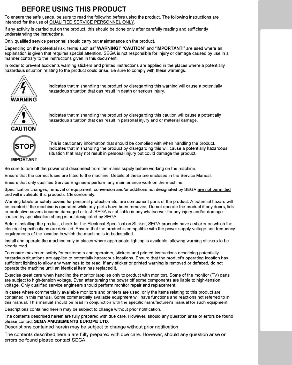
TABLE OF CONTENTS
i
0ii
0v
0
0
101
0
204
2.1
04
2.2
05
0
3
PRECAUTIONSREGARDINGPRODUCTOPERATION-----------------------------
-
06
3.1 BEF0REOPERATION------------------------------------------------------------------------------
-
06
3.2 PAYINGATTENTIONTOCUSTOMERDURINGOPERATION-----------------------------
-
08
0
4
PARTSDESCRIPTIONS------------------------------------------------------------------
-
010
0
5
ACCESSORIES-----------------------------------------------------------------------------
-
011
0
6
ASSEMBLYANDINSTALLATION------------------------------------------------------
014
6.1
016
6.2
017
6.3
023
6.4
027
6.5
028
6.6
029
0
7
PRECAUTIONSWHENMOVINGTHEMACHINE-----------------------------------
-
036
0
8
GAMEDESCRIPTION--------------------------------------------------------------------
-
038
8.1
038
8.2
039
8.3
042
8.4
045
8.5
046
8.6
047
8.7
048
8.8
049
BEFOREUSINGTHEPRODUCT--------------------------------------------------------
TABLEOFCONTENTS--------------------------------------------------------------------
-
HANDLINGPRECAUTIONS-------------------------------------------------------------
INTRODUCTION---------------------------------------------------------------------------
-
CARTRANSMISSION-----------------------------------------------------------------------------
-
TRACKSELECTION--------------------------------------------------------------------------------
-
PRECAUTIONSREGARDINGINSTALLATIONLOCATION------------------------
LIMITATIONOFUSE------------------------------------------------------------------------------
OPERATIONAREA---------------------------------------------------------------------------------
-
CHECKINGASSEMBLY(SETUP)---------------------------------------------------------------
-
GENERALASSEMBLYINFORMATION--------------------------------------------------------
-
FIXINGTHEMASTERANDSLAVECOCKPITSTOGETHER--------------------------------
-
ASSEMBLINGTHEPOP---------------------------------------------------------------------------
INSTALLATIONANDFIXINGINPLACE-------------------------------------------------------
-
CONNECTINGTHEPOWERCABLES-----------------------------------------------------------
-
GAMEOVERVIEW---------------------------------------------------------------------------------
-
GAMESELECTION--------------------------------------------------------------------------------
-
CARSELECTION-----------------------------------------------------------------------------------
-
HIGHSCORES--------------------------------------------------------------------------------------
-
ONSCREENDISPLAY----------------------------------------------------------------------------
-
DRIVERSVIEW-CAMERA-----------------------------------------------------------------------

TABLE OF CONTENTS
0
9
EXPLANATIONOFTESTANDDATADISPLAY-----------------------------------
-
050
9.1
051
9.2 GAMETESTMODE--------------------------------------------------------------------------------
-
052
9.21 SYSTEMINFORMATION-----------------------------------------------------------
-
054
9.22 INPUTTEST---------------------------------------------------------------------------
-
055
9.23 OUTPUTTEST------------------------------------------------------------------------
-
056
9.24 COINSETTINGS---------------------------------------------------------------------
-
057
9.25 SOUNDSETTINGS------------------------------------------------------------------
-
058
9.26 SCREENTEST------------------------------------------------------------------------
-
059
9.27 NETWORKTEST---------------------------------------------------------------------
-
061
9.28 CALIBRATEINPUTS----------------------------------------------------------------
-
062
9.29 BOOK-KEEPING---------------------------------------------------------------------
-
064
9.210 CLOCKSETTINGS-------------------------------------------------------------------
-
068
9.211 GAMESETTINGS--------------------------------------------------------------------
-
069
0
10
CONTROLCOMPONENTS---------------------------------------------------------------
-
070
10.1 STEERINGWHEEL(EXPLODEDDRAWING)------------------------------------------------
-
071
10.2 SHIFTLEVER----------------------------------------------------------------------------------------
-
072
10.21 REMOVINGTHESHIFTLEVER---------------------------------------------------
-
072
10.22 REPLACINGTHESWITCH---------------------------------------------------------
-
073
10.3 ACCELERATORANDBRAKE--------------------------------------------------------------------
-
074
10.31 VOLUMEADJUSTMENTANDREPLACEMENT--------------------------------
-
075
10.32 GREASING----------------------------------------------------------------------------
-
077
10.4 HANDBRAKE---------------------------------------------------------------------------------------
-
078
10.41 REMOVINGTHEHANDBRAKELEVER------------------------------------------
-
078
10.42 REPLACINGTHESWITCH---------------------------------------------------------
-
079
0
11
GRAPHICDISPLAY-----------------------------------------------------------------------
-
081
11.1 CAUTIONANDWARNINGCONCERNINGMONITORSAFETY---------------------------
-
081
11.2 CLEANINGCRTSURFACE------------------------------------------------------------------------
-
082
11.3 ADJUSTMENTPROCEDURES-------------------------------------------------------------------
-
083
0
12
COINSELECTORANDCREDITSETTINGS-------------------------------------------
-
087
12.1 CLEANINGTHECOINSELECTOR---------------------------------------------------------------
-
087
12.2 ADJUSTINGPRICEOFPLAY--------------------------------------------------------------------
-
089
12.3 SR3OPTIONS-TEACHANDRUNPROGRAMMING---------------------------------------
-
093
SWITCHUNITANDCOINMETER--------------------------------------------------------------
-

TABLE OF CONTENTS
0
13
FLUORESCENTTUBESANDLAMPREPLACEMENT-------------------------------
-
095
13.1 BILLBOARD-TUBEREPLACEMENT-----------------------------------------------------------
-
096
13.2 BILLB0ARD-RACELEADERLAMPS----------------------------------------------------------
-
098
13.3 BILLBOARD-SIDELIGHTLEDCLUSTER-----------------------------------------------------
-
0100
13.4 BUTTONLAMPS-CONTROLPANEL---------------------------------------------------------
-
0102
0
14
PERIODICINSPECTION------------------------------------------------------------------
-
0104
0
15
TROUBLESHOOTING--------------------------------------------------------------------
-
0106
15.1 TROUBLESHOOTING-(WHENNOERRORMESSAGEISSHOWN)---------------------
-
0106
0
16
GAMEBOARD-----------------------------------------------------------------------------
-
0110
16.1 CONTROLBOARDS-LOCATIONS-------------------------------------------------------------
-
0111
16.2 CONTROLBOARDS-IDENTIFICATION-------------------------------------------------------
-
0114
0
17
COMMUNICATIONPLAY---------------------------------------------------------------
-
0116
17.1 INSTALLATIONPRECAUTIONS----------------------------------------------------------------
-
0116
17.2 CONNECTINGTHECOMMUNICATIONCABLE----------------------------------------------
-
0118
17.3 NETWORKPLAYSETTINGS---------------------------------------------------------------------
-
0120
17.4 NETWORTPLAYPRECAUTIONS---------------------------------------------------------------
-
0121
0
18
DESIGNRELATEDPARTS---------------------------------------------------------------
-
0123
19
PARTSLIST-SUBASSEMBLYBREAKDOWN---------------------------------------
-
0125
19.1 PARTSLIST-COMPONENTBREAKDOWN--------------------------------------------------
-
0126
0
20
WIRINGCOLOURCODETABLE--------------------------------------------------------
-
0167
0
21
WIRINGDIAGRAM-----------------------------------------------------------------------
-
0168
21.1 WIRINGDIAGRAMD1-4------------------------------------------------------------------------
-
0168
21.2 WIRINGDIAGRAMD2-4------------------------------------------------------------------------
-
0169
21.3 WIRINGDIAGRAMD3-4------------------------------------------------------------------------
-
0170
0
0
INTRODUCTION
SPECIFICATIONS
.
NOTE : The contents herein described are subject to change without notice.

Denition of 'Site Maintenence Personnel or Other Qualied Individuals
1 HANDLING PRECAUTIONS
Wheninstallingorinspectingthemachine,beverycarefulofthefollowingpointsandpayattentionto
ensurethattheplayercanenjoythegamesafely.
Non-compliancewiththefollowingpointsorinappropriatehandlingrunningcountertothecautionary
mattershereinstatedcancausepersonalinjuryordamagetothemachine.
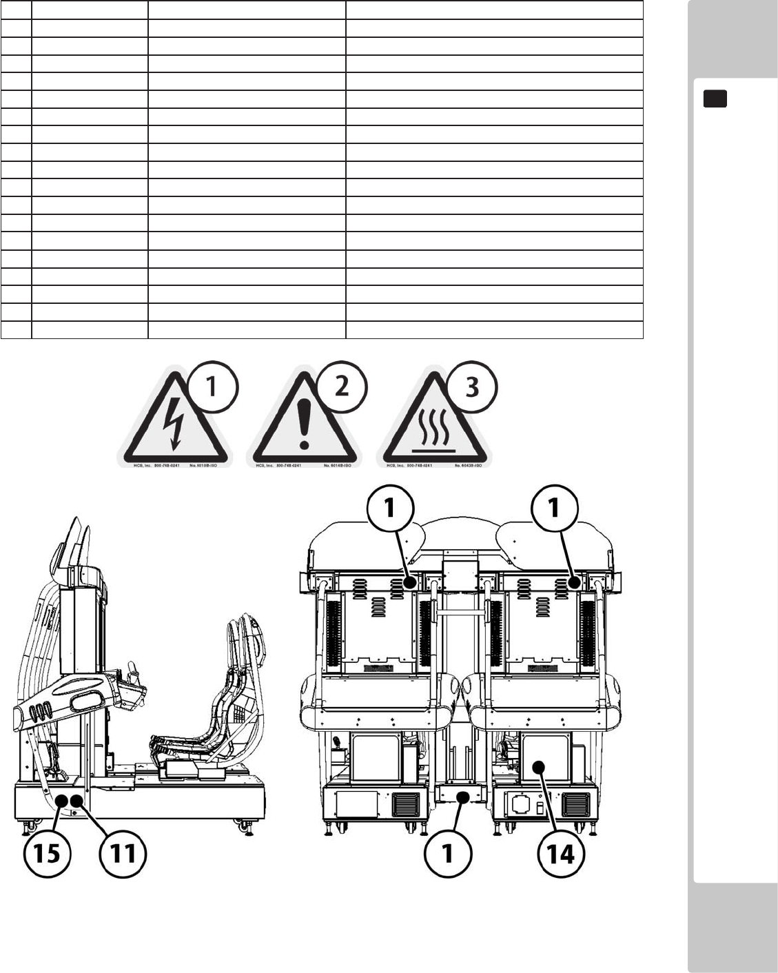
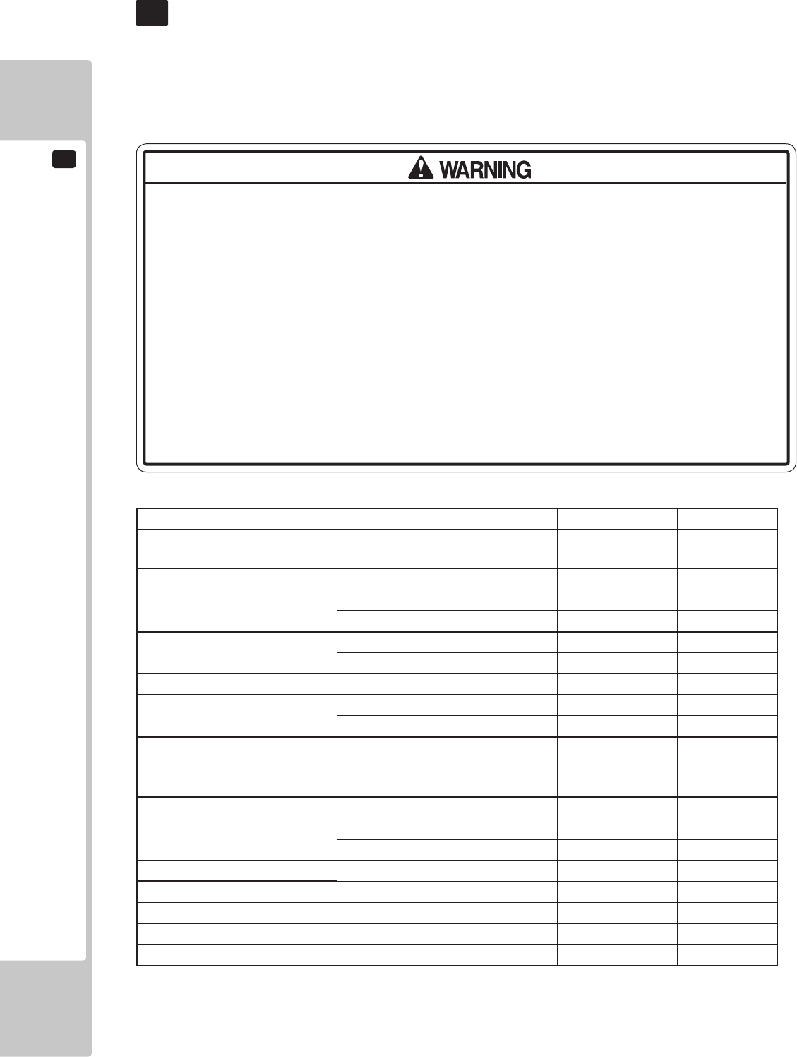
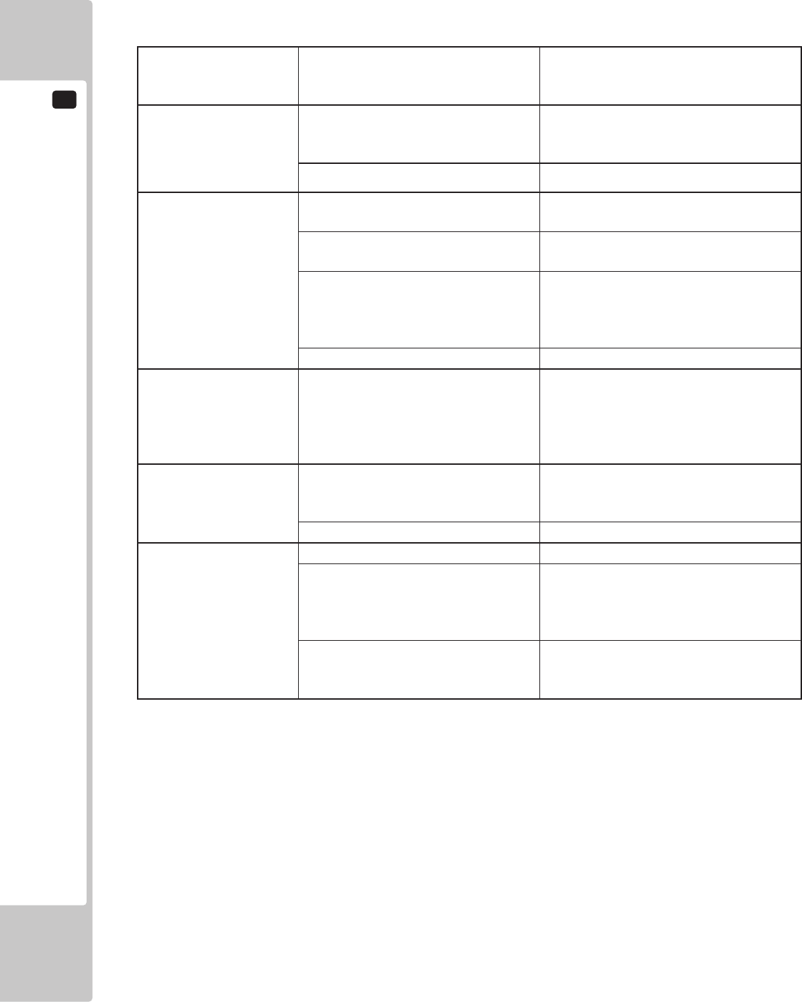
Number Description LOCATION
1 LB1102 DANGEROUS VOLTAGE Lower Panel Wire Cover
1 LB1102 DANGEROUS VOLTAGE LCD Display Back Cover
1 LB1102 DANGEROUS VOLTAGE Top of Billboard at Back
2 LB1103 CAUTION STICKER Inside Coin Tower - Coin Door
3 LB1104 CAUTION HOT SURFACE Inside Billboard 'FL' Lamp Box
4 421-7501-10 FL 40W Inside Billboard 'FL' Lamp Box
5 LB1111 PLEASE RECYCLE Inside Base
6 LB1101 WARNING BATTERY Inside Base on Game board
7 440-WS0220UK WARNING - TRAP HAZZARD Inside Control Panel by Steering Gears
8 LB1096 PROTECTIVE EARTH On AC Units
9 LB1126-5-250 FUSE LABEL 5A 250V On AC Units
10 LB1126-10-250 FUSE LABEL 10A 250V On AC Units
11 421-7988-91UK SERIAL NUMBER STICKER UK Lower Left Side of Cabinet
12 421-8543UK STICKER CABINET L UK Rear of Cabinet - (P1)
13 421-8544UK STICKER CABINET R UK Rear of Cabinet - (P2)
14 LB1046 TESTED FOR ELEC SAFETY Back of Cabinet alongside the AC Unit (P1)
15 LB1130 WEEE WHEELIE BIN Lower Left Side of Cabinet
STICKER DISPLAY AND WARNING LABEL INFORMATION
2 PRECAUTIONS REGARDING INSTALLATION LOCATION
2-1 LIMITATAION OF USE
ELECTRICITY CONSUMPTION
MAX : 3.5A (AC 230V ~ 50HZ)
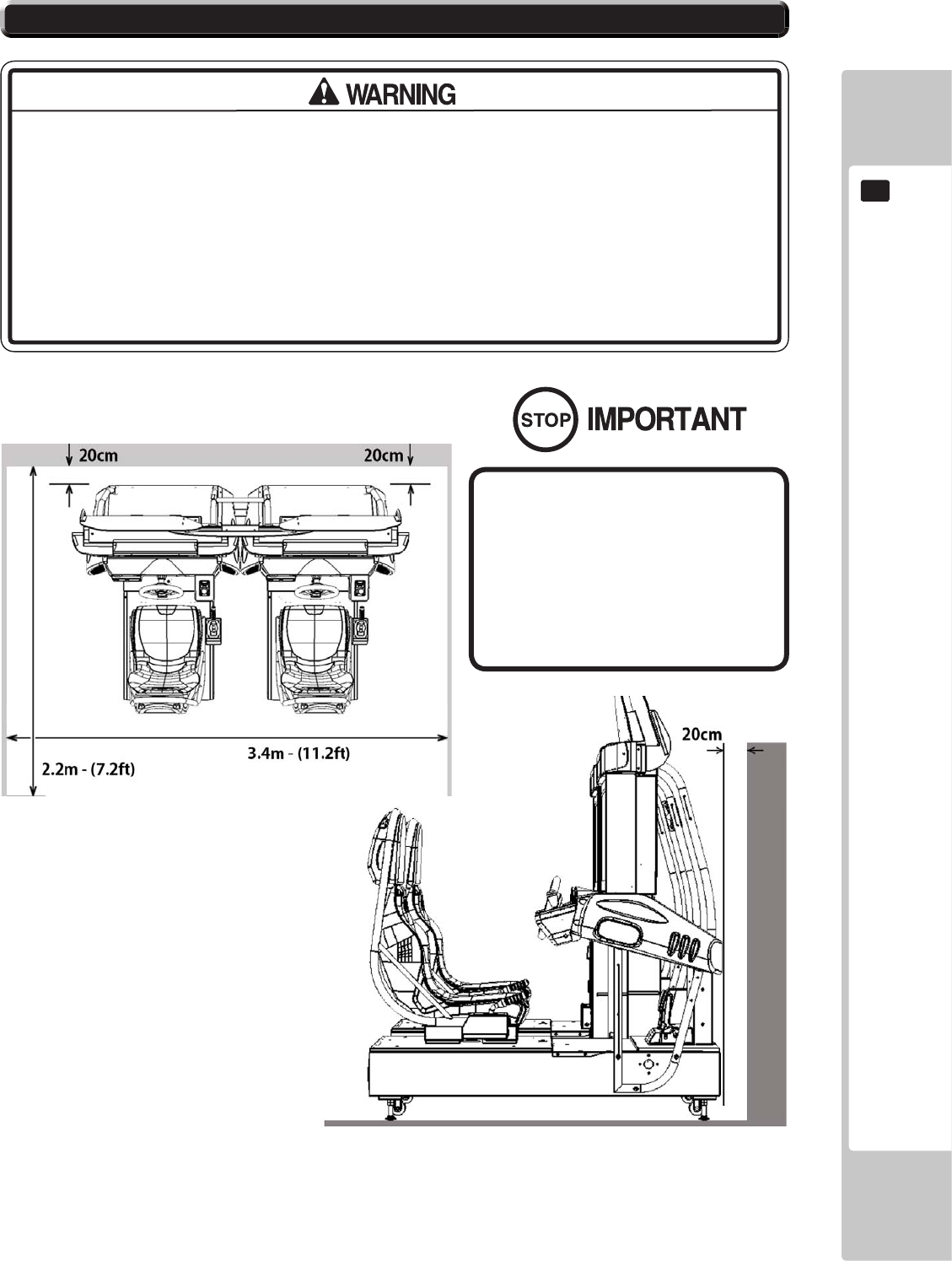
2-2 OPERATIONAL AREA
INSTALLATION SPACE
2-2 Fig 01
2-2 Fig 02
2-2 Fig 01
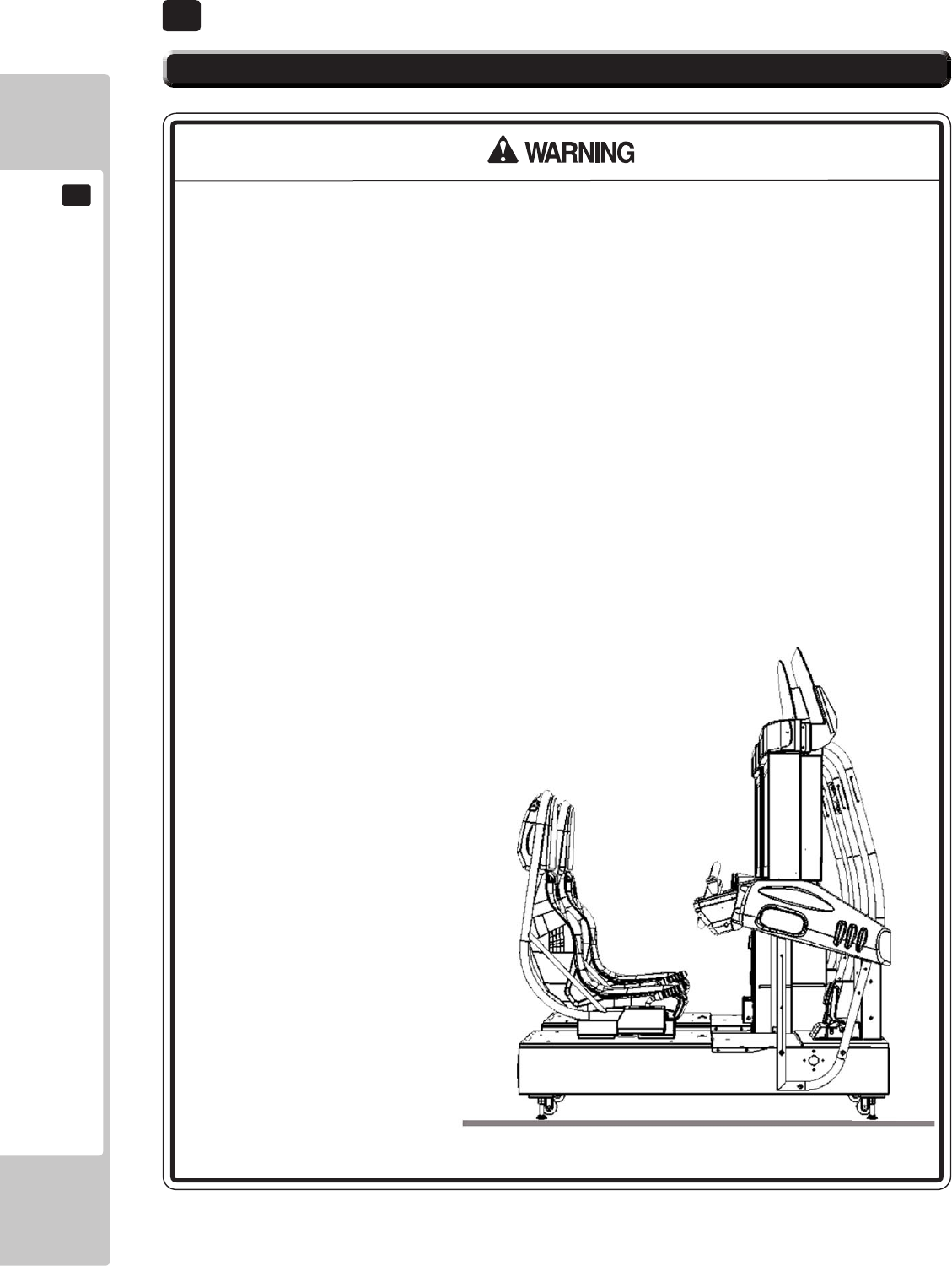
3 PRECAUTIONS REGARDING PRODUCT OPERATION
3.1 BEFORE OPERATION
3.1 BEFORE OPERATION
3.2 PAYING ATTENTION TO CUSTOMERS DURING OPERATION
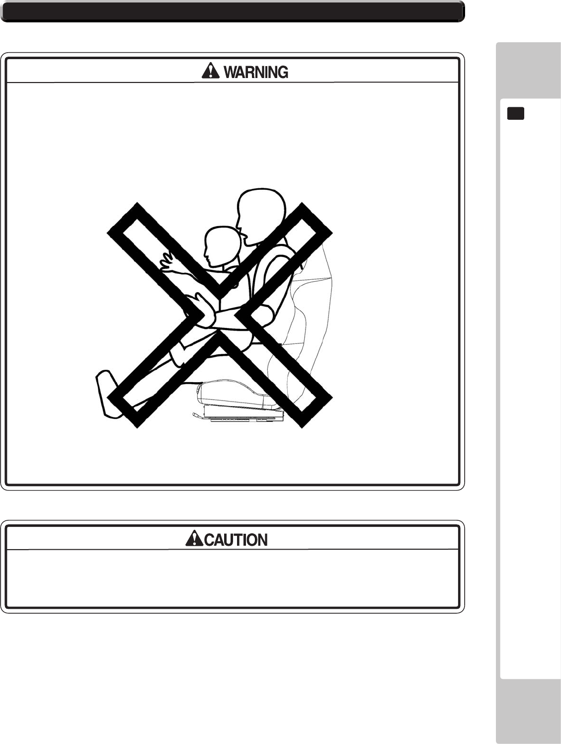
3.2 PAYING ATTENTION TO CUSTOMERS DURING OPERATION
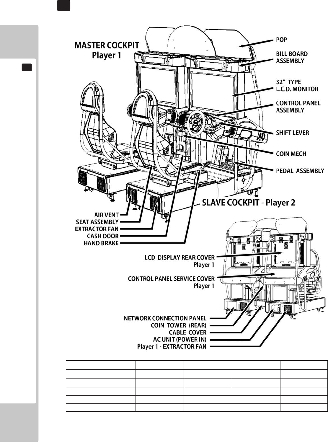
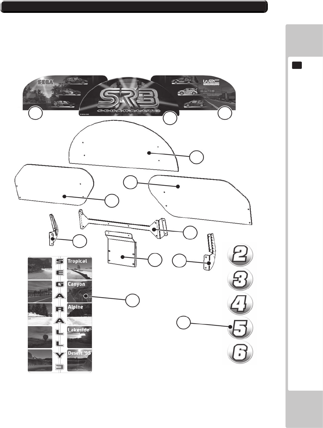
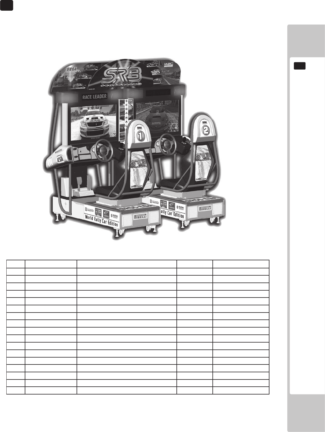
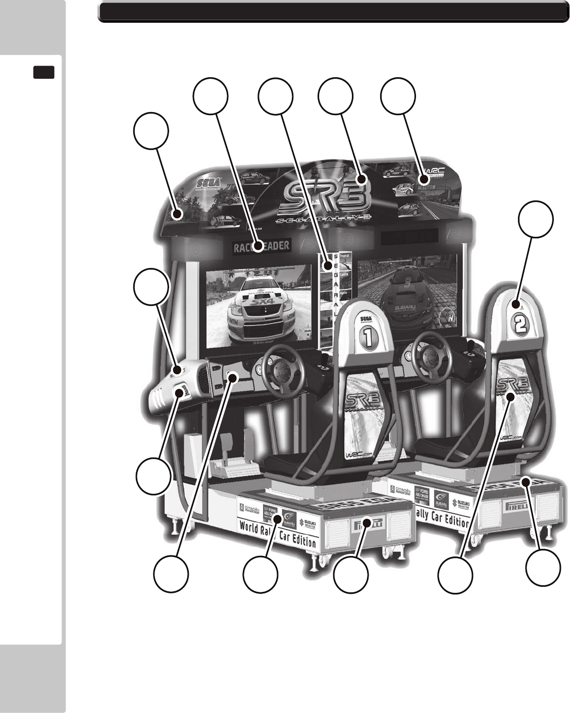
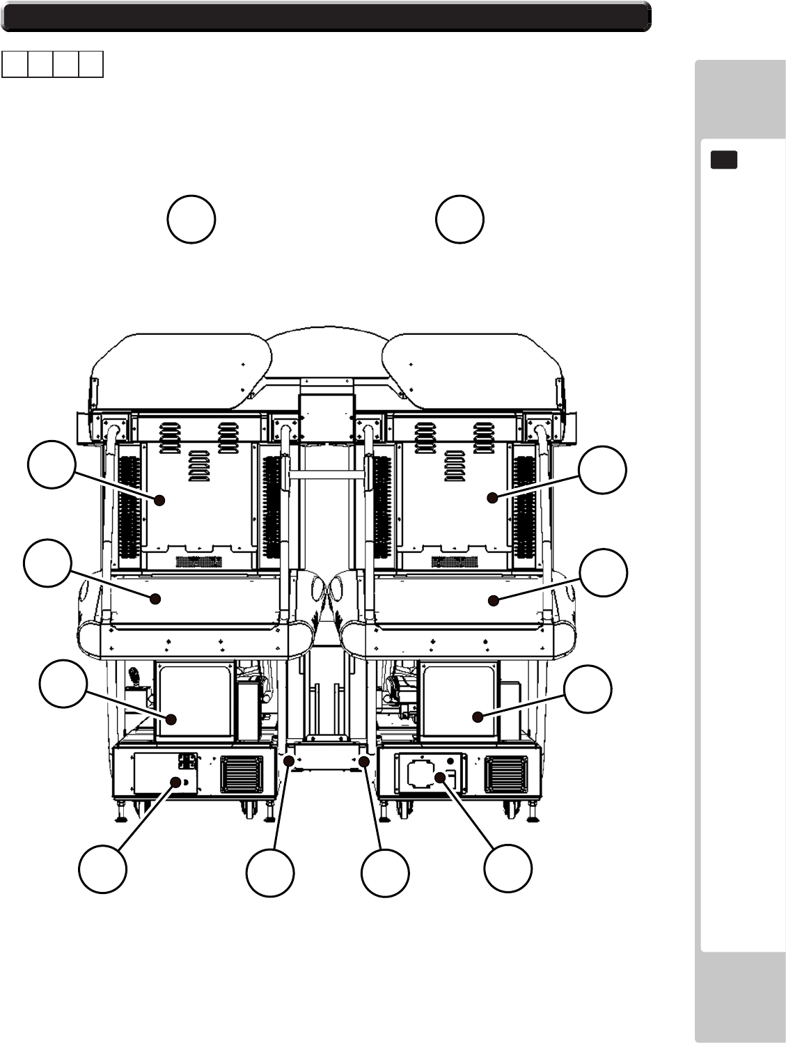
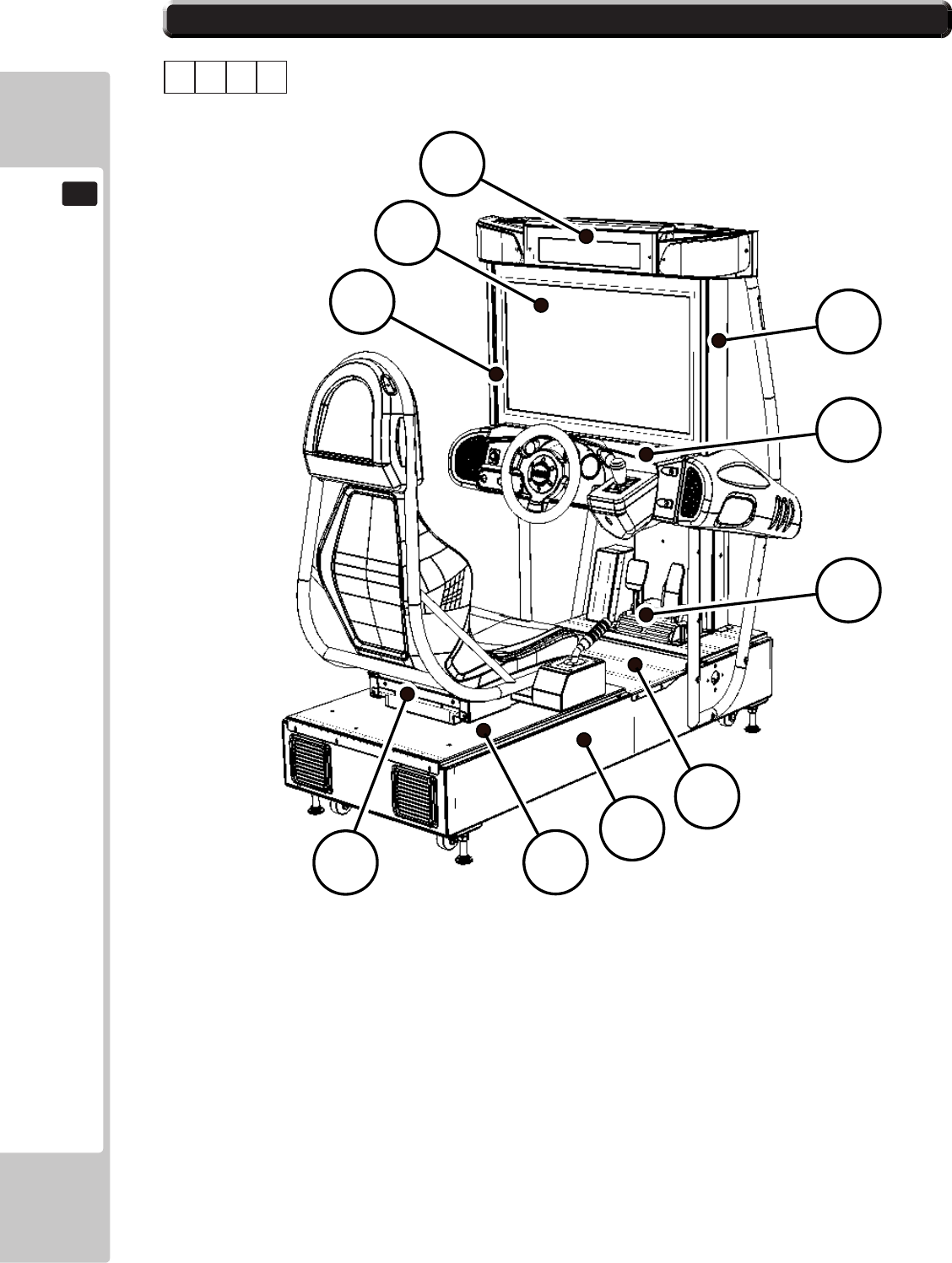
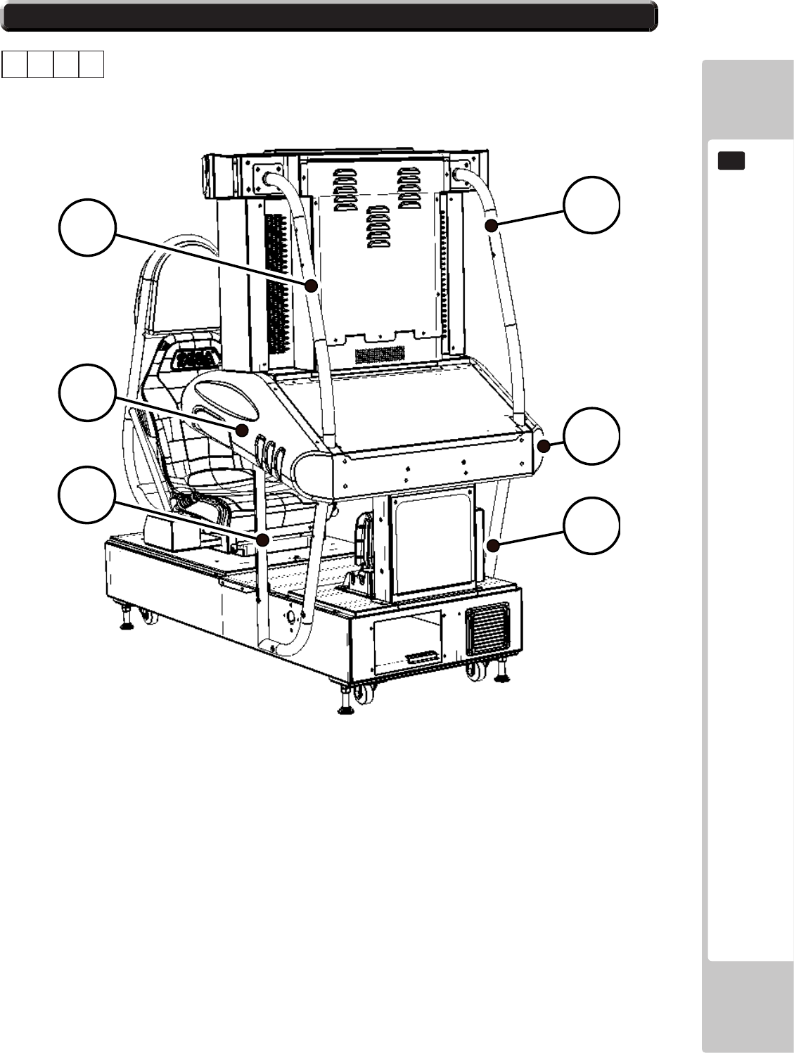
4 PART DESCRIPTIONS
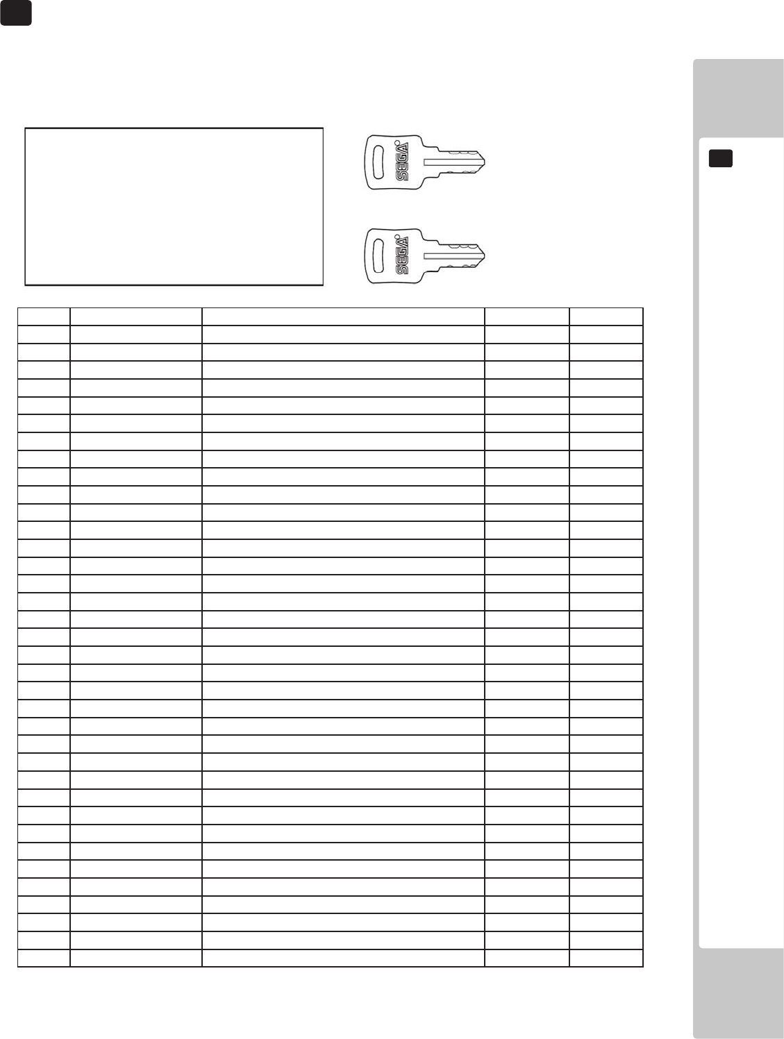
Conrm that the accessories list in the table below are present when setting up the product.
Accessories marked “Spare” in the note column are consumable items but included as spares.
TABLE 5A - ACCESSORIES
5 ACCESSORIES
DESCRIPTIONOWNERSMANUAL
PTNUMBER(QTY)420-0006-02UK
NOTEThisManual
Partsnotlabeledwithpartnumbersareas
yetunregisteredorcannotberegistered.
Besuretohandleallpartswithcare,as
somepartsarenotavailableforpurchaseas
separateitems.
KEYMASTER
220-5793-2-A001(2)
Foropening/closing
thedoors
KEY(2)
CASHBOXDOOR
SEQ NUMBER DESCRIPTION QUANTITY NOTE
2
3
4
104
105
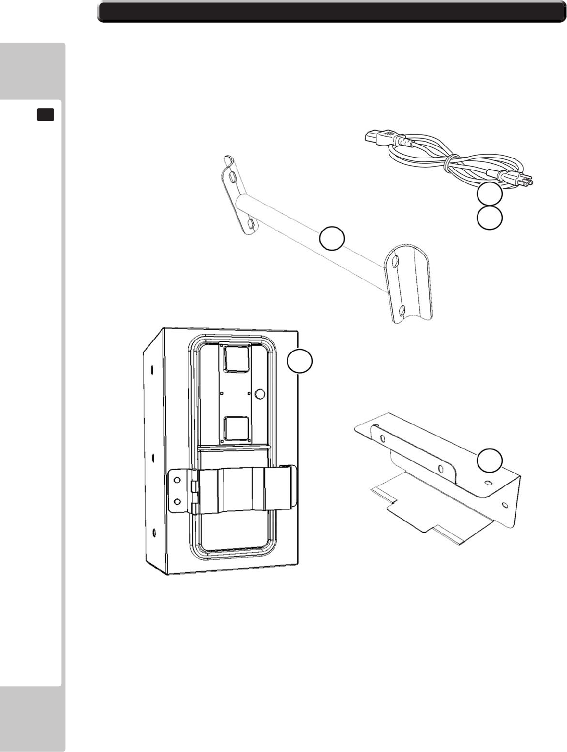
MAINSLEADS
LM1227(1xUK)
LM1246(1xEURO)
5-0 ACCESSORIES - COMPONENT IDENTIFICATION
21
21
22
22
23
23
24
25
26
27
29
30
5-0 ACCESSORIES - COMPONENT IDENTIFICATION
6 ASSEMBLY & INSTALLATION
Installation and assembly of this product should take place in the following sequence.
6-2 FIXING THE MASTER AND SLAVE COCKPITS TOGETHER
6-4 INSTALLATION AND SECURING IN PLACE
6-5 CONNECTING POWER CABLE AND GROUND
6-6 CHECKING ASSEMBLY (SET UP)
6-1 GENERAL ASSEMBLY INFORMATION
6-3 ASSEMBLING THE POP TO THE MACHINE
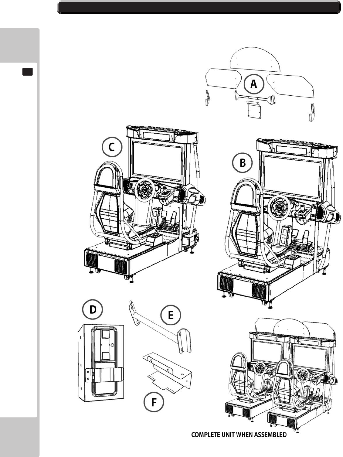
6-1 GENERAL ASSEMBLY INFORMATION
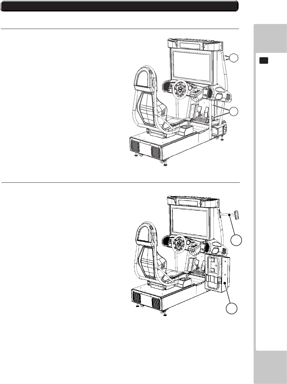
6-1 Fig 01
A - POP Assembly Kit
B - Master Cockpit
C - Slave Cockpit
D - Coin Tower
E - Joint Pipe
F - Wire Cover
G - Power Loom (Not Shown)
H - LAN Coupler (Not Shown)
6-2 FIXING THE MASTER AND SLAVE COCKPITS TOGETHER
1
X
Y
E
D
2
3
6-2 FIXING THE MASTER AND SLAVE COCKPITS TOGETHER
4
5
6
6-2 FIXING THE MASTER AND SLAVE COCKPITS TOGETHER
CDB
ʻXʼʻXʼ
ʻXʼʻXʼ
F
7
6-2 FIXING THE MASTER AND SLAVE COCKPITS TOGETHER
IDENTIFICATION OF CONNECTORS
EARTH CONNECTION
AB
C
D
E
6
7
F
EE1
E2
8
A2 A A1
D2
D1
B2 C2 B1 B2
9
6-2 FIXING THE MASTER AND SLAVE COCKPITS TOGETHER
COCKPIT CONNECTI0NS
10
6-2 FIXING THE MASTER AND SLAVE COCKPITS TOGETHER
.
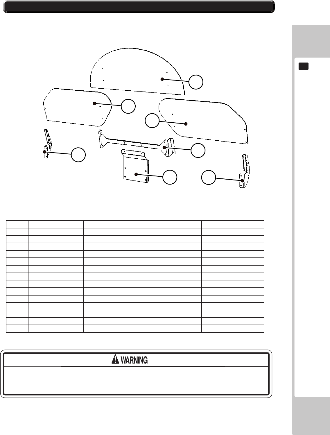
6-3 ASSEMBLING THE POP TO THE MACHINE
POP COMPONENTS - IDENTIFICATION
21
22
23
24
25
26
27
6-3 Fig 01
SEQ NUMBER DESCRIPTION QUANTITY REF
M4X16 MSCR TH BLK
M4 WSHR 16OD FLT BLK
M4 WSHR 16OD FLT PAS
M4 NUT FLT SER PAS
M6X16 BLT W/S BLK
M6 WSHR FORM A FLT BLK
THIS WORK ON TOP OF THE CABINET, SHOULD NOT BE UNDERTAKEN
WITHOUT THE USE OF A SUITABLE STEP OR FOOTSTOOL.
A
6-3 ASSEMBLING THE POP TO THE MACHINE
B
C
XX
25
24
A
Y
Y
Y
Y
21
B
COCKPIT2COCKPIT1
Z
Z
Z
Z
6-3 Fig 03
6-3 Fig 02
6-3 Fig 04
6-3 FIXING THE MAIN CABINET TO THE DLP CABINET
D
6-3 ASSEMBLING THE POP TO THE MACHINE
E
F
6-3 Fig 07
6-3 Fig 05
Y
Y
22
26
D
COCKPIT1
Z
Z
X
X
Y
Y
23
27
6-3 Fig 06
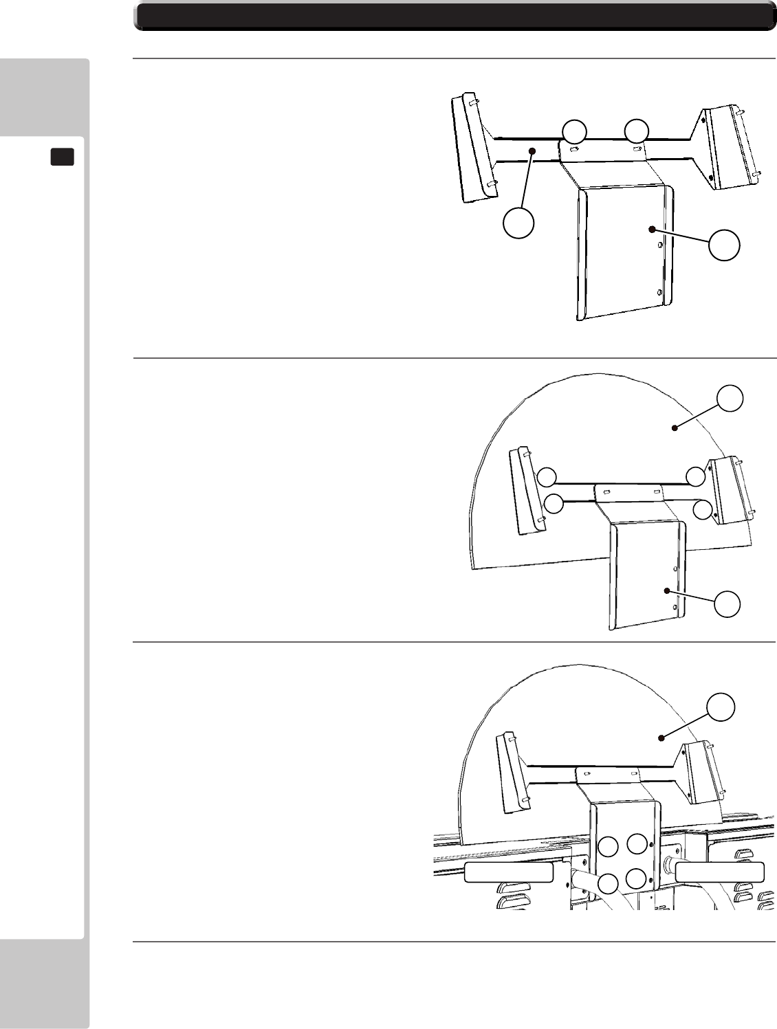
Components required, ‘22’ & ‘26’
Take Bracket ‘26’ and remove the 2x
M4 Screws (205) marked ‘Y’ from the
channel section of the bracket.
See 6-3 Fig 05
With the printed side to the front,
position the Left POP ‘22’ into the
channel in the bracket ‘26’ lining up
the hole positions ‘Y’ and replace
and tighten the M4 Screws.
Remove the 2 M4 Nuts and Washers
(205, 207) from ‘X’ and the 2 M6 Bolts
and Washers (209, 210) from ‘Z’
Position ‘D’ so that the two remain-
ing holes locate over the M4 studs ‘X’,
and Lining up the 2 holes ‘Z’ fit and
tighten the M6 Bolts and Washers,
then replace and tighten the M4 nuts
and Washers at ‘X’
Components required, ‘23’ & ‘27’
Take Bracket ‘27’ and remove the 2x
M4 Screws (205) marked ‘Y’ from the
channel section of the bracket.
See 6-3 Fig 07
With the printed side to the front,
position the Left POP ‘23’ into the
channel in the bracket ‘27’ lining up
the hole positions ‘Y’ and replace
and tighten the M4 Screws.
6-3 FIXING THE MAIN CABINET TO THE DLP CABINET
6-3 ASSEMBLING THE POP TO THE MACHINE
H
I
6-3 Fig 09
Z
Z
X
X
F
COCKPIT2
G
6-3 Fig 08
Remove the 2 M4 Nuts and Wash-
ers (205, 207) from ‘X’ and the 2 M6
Bolts and Washers (209, 210) from ‘Z’
Position ‘F’ so that the two remain-
ing holes locate over the M4 studs
‘X’ , and Lining up the 2 holes ‘Z’ t
and tighten the M6 Bolts and Wash-
ers, then replace and tighten the M4
nuts and Washers at ‘X’
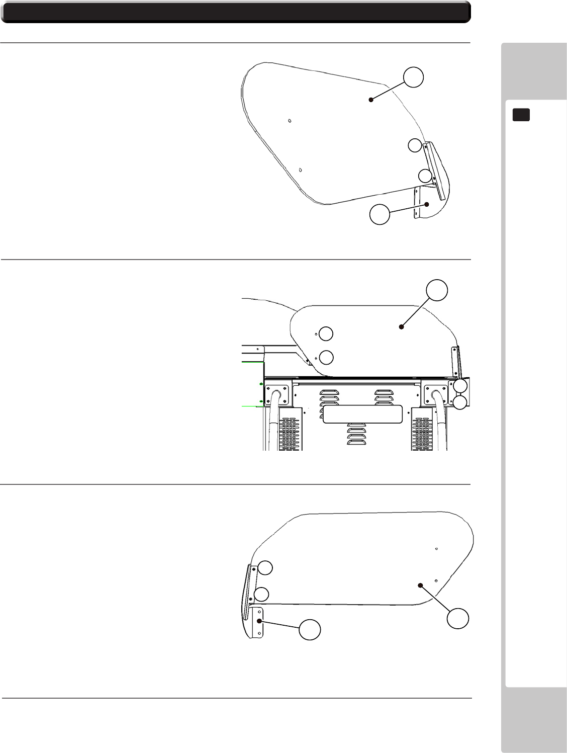
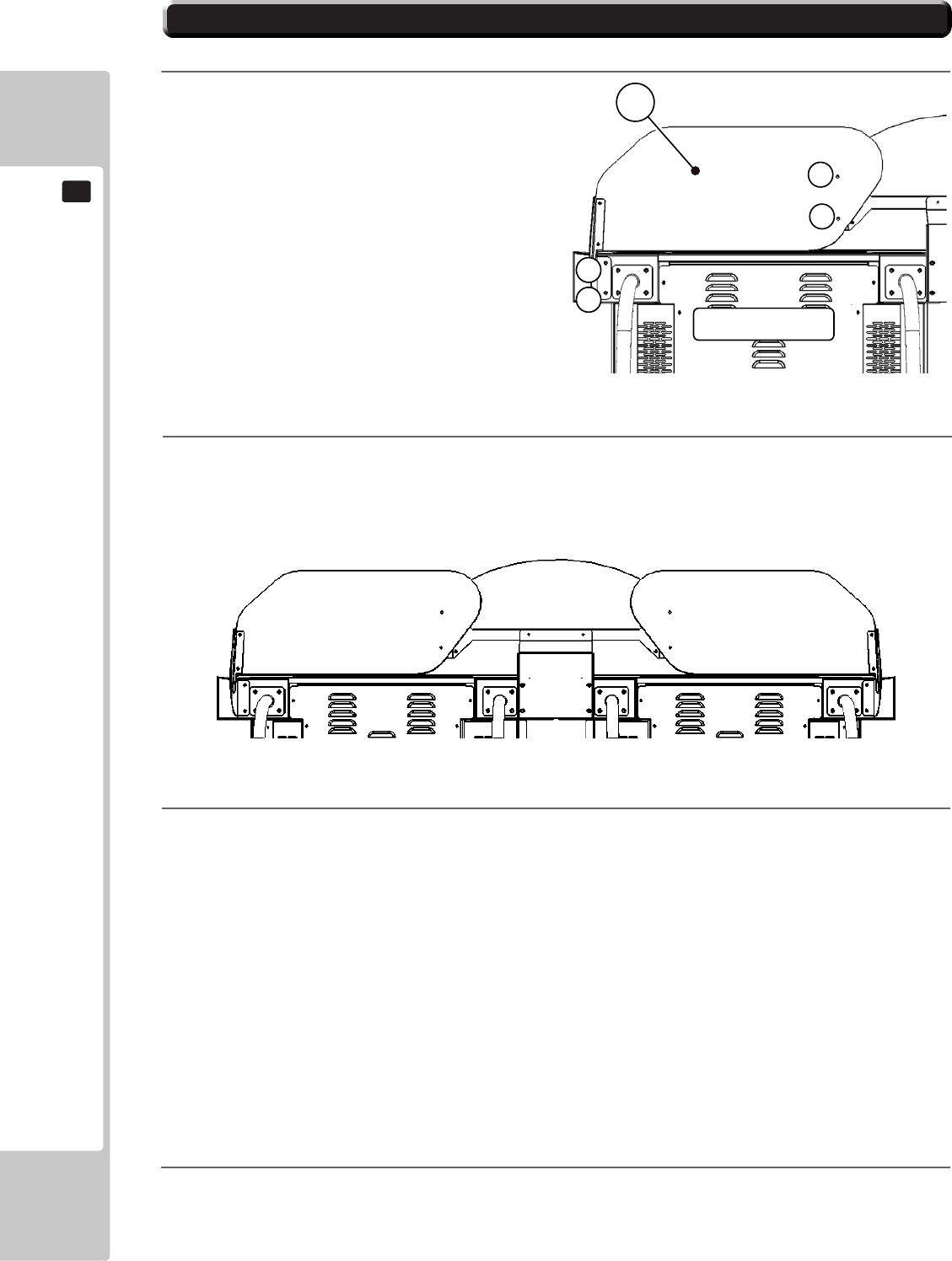
POP ASSEMBLY FULLY ASSEMBLED ONTO MACHINE
6-4 INSTALLATION AND SECURING IN PLACE
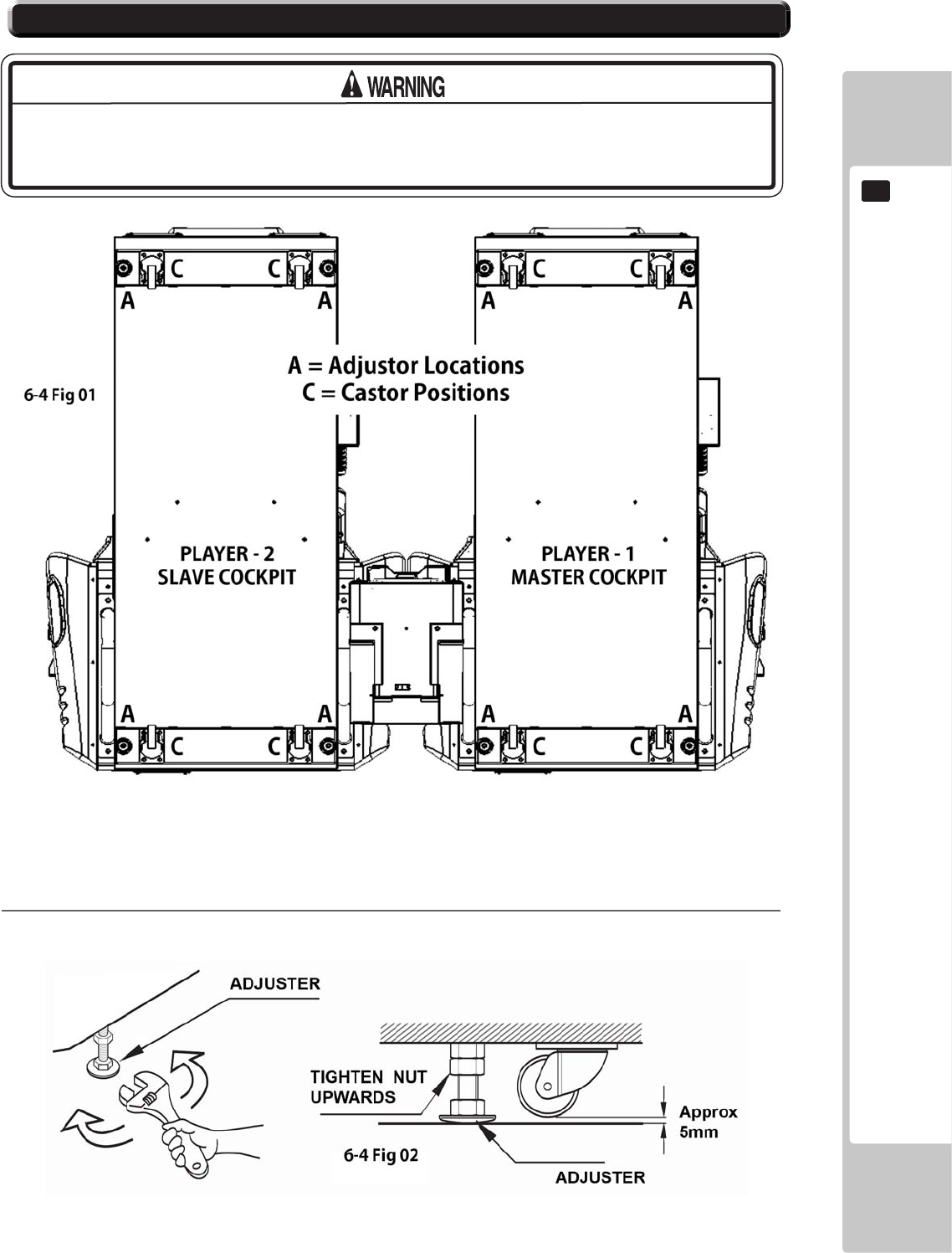
6-4- Fig 02 - Showing the correct details for Adjustment.
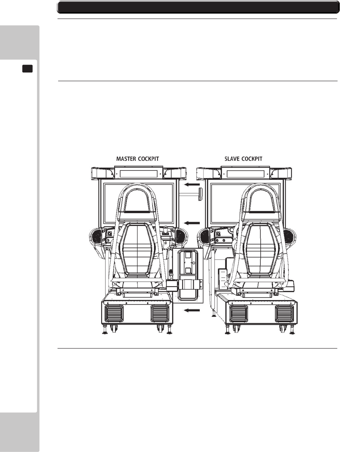
‘SEGA RALLY 3 Twin’ consists of two Base Units : MASTER and SLAVE Cockpits.
6-4 Fig 01 - Shows the location of the Castors (C) and Fixing Adjusters (A).
During the installation of the units, the Fixing Adjustment should be performed
to ensure that the units are stable.
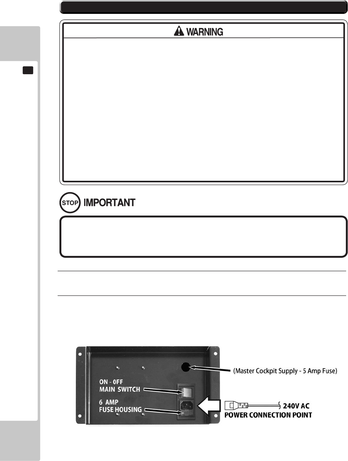
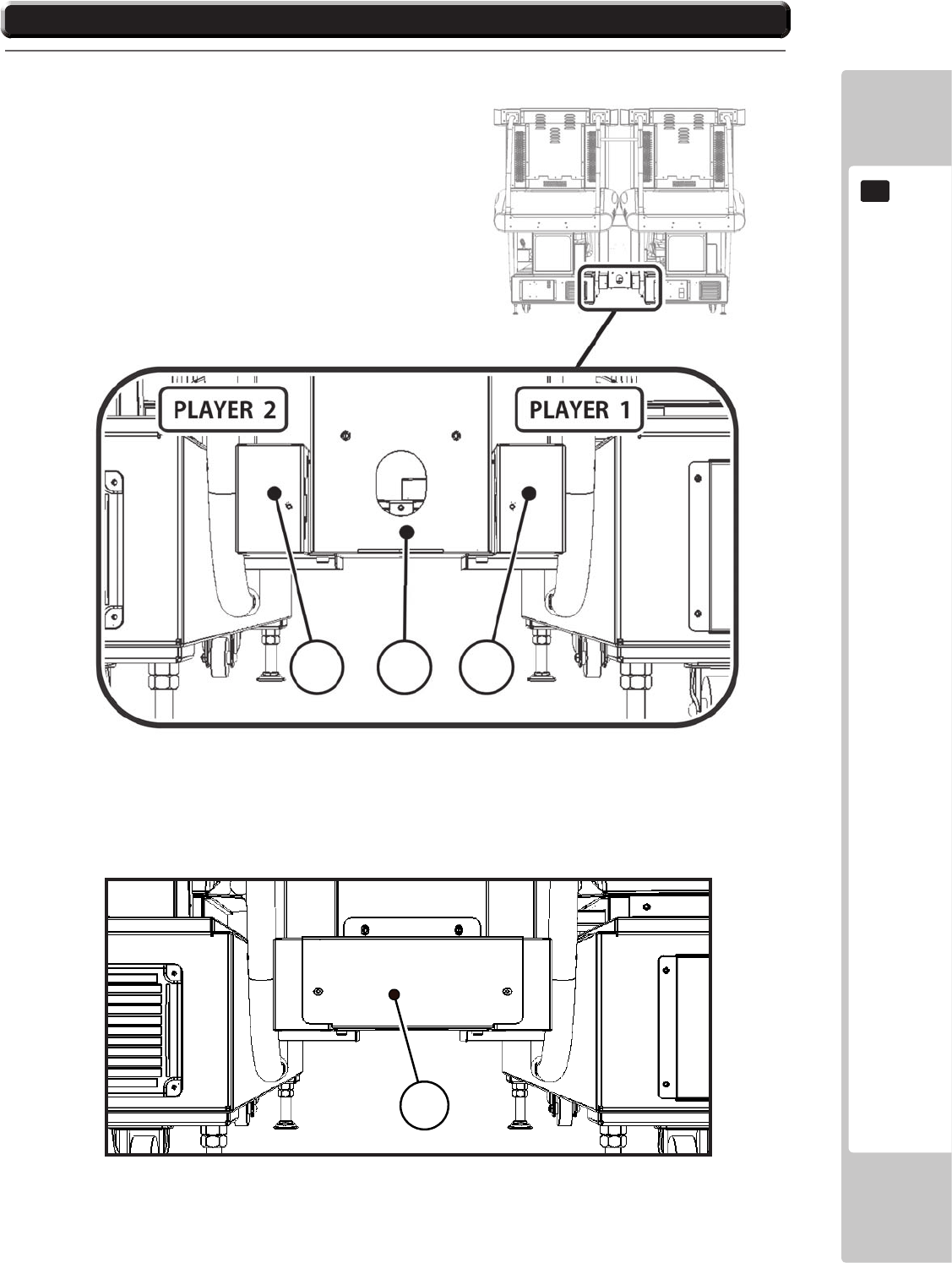
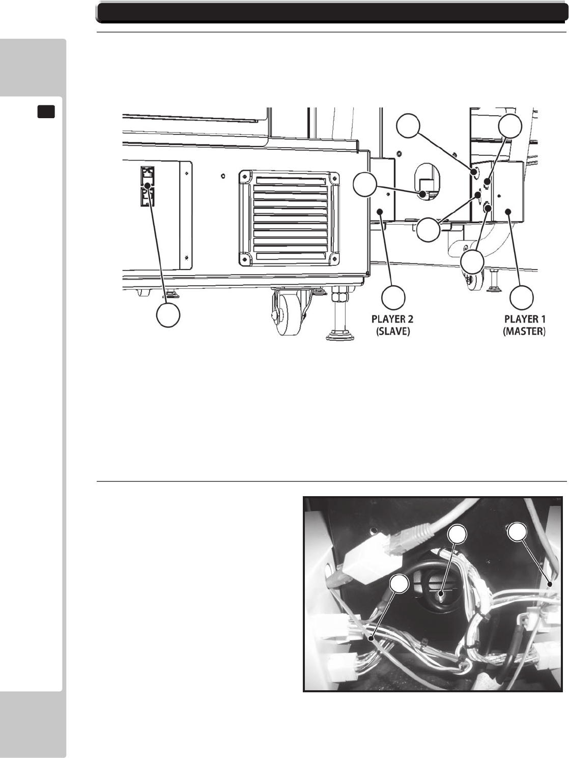
6-5 CONNECTION OF POWER AND GROUND
Before switching Power ON, make sure that the ‘Machine Grounding’ has been
established with a ground wire inside the ‘Power Cable’ and that the ‘Mains Out-
let’ supplying the machine is tted with a suitable ‘Earth Point’
1
2
6-6 CHECKING ASSEMBLY - SET UP
A = TEST; B = SERVICE; C = VOLUME CONTROL;
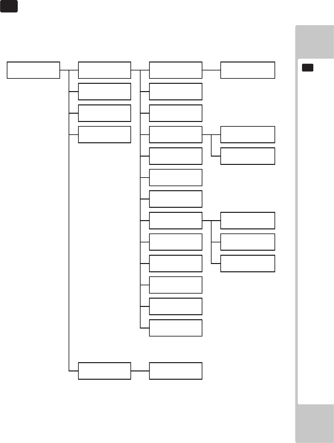
GAME TEST MODE
The following options are available from the System Menu Test
The following 4 TEST should be selected and checked individually to prove the functionality
of all peripheral components. For full information on all the Test and Set Up Procedures,
go to Chapter 9 - EXPLANATION OF TEST AND DATA DISPLAY
PLAYER 1
TEST MENU
SELECT WITH SERVICE BUTTON
AND PRESS TEST BUTTON
SYSTEM INFORMATION
INPUT TEST
OUTPUT TEST
MOTION BASE TEST
COIN SETTINGS
SOUND SETTINGS
SCREEN TEST
NETWORK TEST
CALIBRATE INPUT
BOOKKEEPING
CLOCK SETTINGS
GAME SETTINGS
RESET TO FACTORY DEFAULT
EXIT
>>
When he machine has been switched ON for the rst time after installation, open the
Coin Door and Press the ‘TEST’ Button which is located on the VTS board at the back
the compartment. This will give entry to the ‘TEST MENU’

6-6 INPUT TEST
Select‘INPUTTEST’fromthe‘GameTestMode’Menutodisplay‘InputTest’Menu.
PLAYER 1
INPUT TEST
PRESS TEST AND SERVICE BUTTON
TO EXIT
STEERING : 0000
BRAKE : 0000
ACCELERATOR : 0000
START BUTTON : OFF
VIEW BUTTON : OFF
HANDBRAKE : OFF
GEARSHIFT UP : OFF
GEARSHIFT DOWN : OFF
MOTION STOP : OFF
MOTION LIMIT L TOP : OFF
MOTION LIMIT L BOTTOM : OFF
MOTION LIMIT R TOP : OFF
MOTION LIMIT R BOTTOM : OFF
TEST BUTTON : OFF
SERVICE BUTTON : OFF
COIN INPUT : OFF
EXIT
>>
6-6 CHECKING ASSEMBLY - SET UP

6-6 INPUT TEST
Select‘INPUTTEST’fromthe‘GameTestMode’Menutodisplay‘InputTest’Menu.
6-6 CHECKING ASSEMBLY - SET UP
OUTPUT TEST
Select‘OUTPUTTEST’fromthe‘GameTestMode’Menutodisplay‘OutputTest’Menu..
PLAYER 1
OUTPUT TEST
SELECT WITH SERVICE BUTTON
AND PRESS TEST BUTTON
START LAMP OFF
VIEW LAMP OFF
RACE LEADER LAMP OFF
HEADLIGHTS OUTER LAMPS OFF
HEADLIGHTS INNER LAMPS OFF
REAR LIGHTS OUTER LAMPS OFF
REAR LIGHTS INNER LAMPS OFF
MOTION STOP LAMP OFF
RED LINE LAMP OFF
BLUE LINE LAMP OFF
EXIT
>>

SOUND SETTINGS
PLAYER 1
SOUND SETTINGS
SELECT WITH SERVICE BUTTON
AND PRESS TEST BUTTON
ATTRACT SOUND OFF
MUSIC VOLUME 85
EFFECT VOLUME 75
VOICE VOLUME 60
TEST MUSIC OFF
TEST EFFECT OFF
TEST VOICE OFF
TEST FRONT SPEAKERS OFF
TESR REAR SPEAKERS OFF
TEST WOOFER OFF
EXIT
>>
6-6 CHECKING ASSEMBLY - SET UP

SCREEN TEST
Select‘SCREENTEST’fromthe‘GameTestMode’Menutodisplay‘ScreenTest’Menu..
COLOURBARS
PLAYER 1
SCREEN TEST
SELECT WITH SERVICE BUTTON
AND PRESS TEST BUTTON
COLOUR BARS
BRIGHTNESS
GRID ALIGNMENT
EXIT
>>
YELLOW CYAN GREEN PURPLE RED BLUE BLACK
WHITE
6-6 CHECKING ASSEMBLY - SET UP

SCREEN TEST (Continued)
BRIGHTNESS
GRIDALIGNMENT
6-6 CHECKING ASSEMBLY - SET UP

NOTES ON MACHINE ASSEMBLY
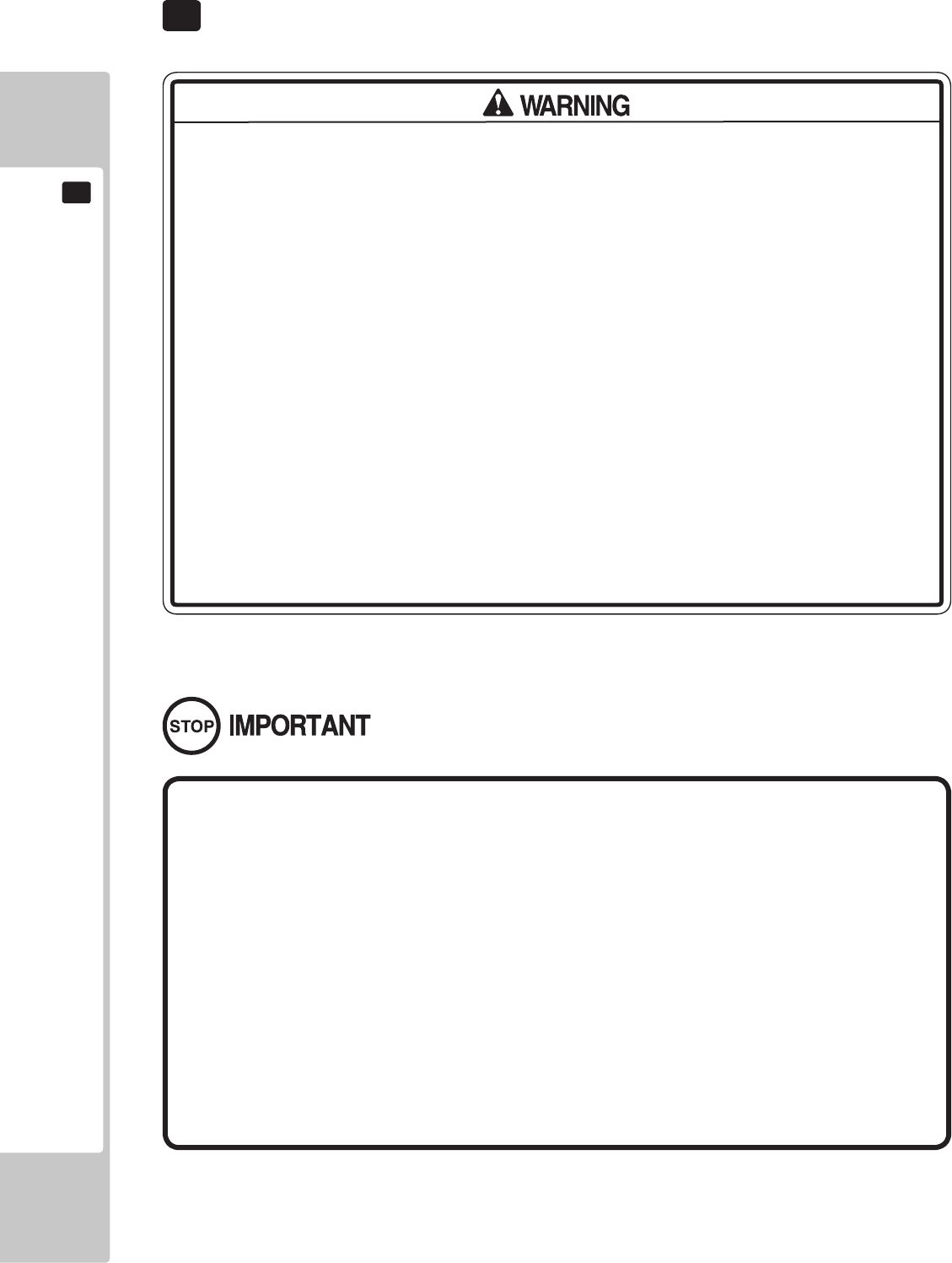
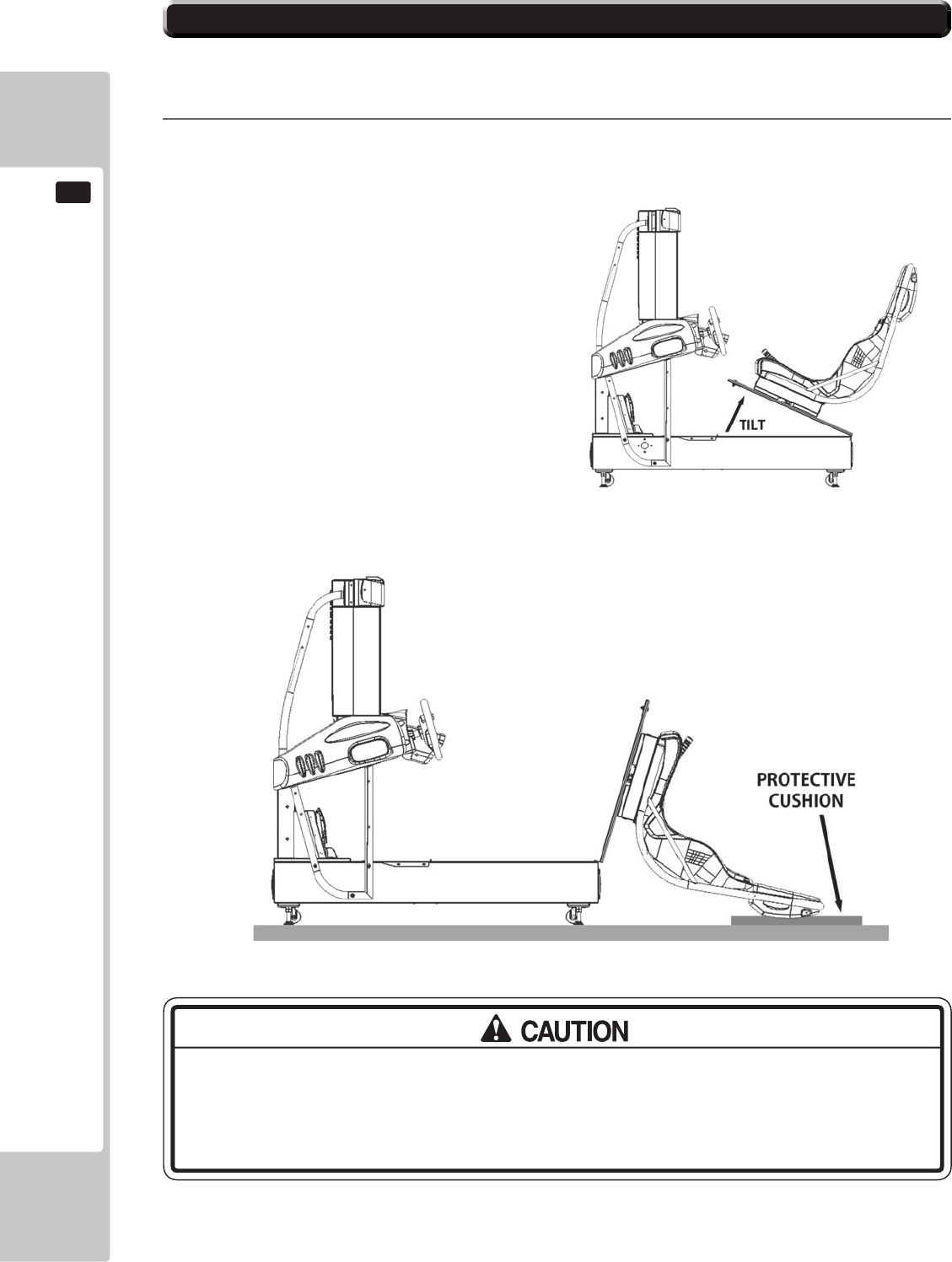
7 PRECAUTIONS WHEN MOVING THE MACHINE
‘RAISE THE ADJUSTERS AS HIGH AS POSSIBLE’

8 GAME DESCRIPTION
The following explanations apply when the product is functioning satisfactory.
Should the be any actions dierent from the following contents, some sort of fault may have
occurred. Immediately look into the cause of the fault and eliminate the cause thereof to ensure
satisfactory operation.
8-1 GAME OVERVIEW
Championship Mode – 1 player
Quick Race – 1 to 6 players
Classic Mode – 1 to 6 players

urningthe‘SteeringWheel’leftandrightwillchangethe
ScreendisplaytoQUICKRACEandCLASSICModeinturn.
WhenthedesiredGameModeisdisplayed,theselectionismadebypressingtheAcceleratorpedal
orStartbuttontoconrmthechoice.
Duringthisselectionsequence,aCOUNTDOWNisbeingdisplayedinthetoprighthandcornerof
thescreen.Ifthereisnoorlittleinterventionshownbytheplayerduringthistime,whateverGame
ModeisbeingdisplayedonthescreenonTIMEOUTwillautomaticallybeselectedandthegame
willadvancetothenextStage,SELECTCAR.
8-2 GAME SELECTION

1
CHAMPIONSHIP MODE – 1 player
8-2 GAME SELECTION

3
Classic Mode - 1 to 6 players
2
QUICK RACE – 1 to 6 players
8-2 GAME SELECTION
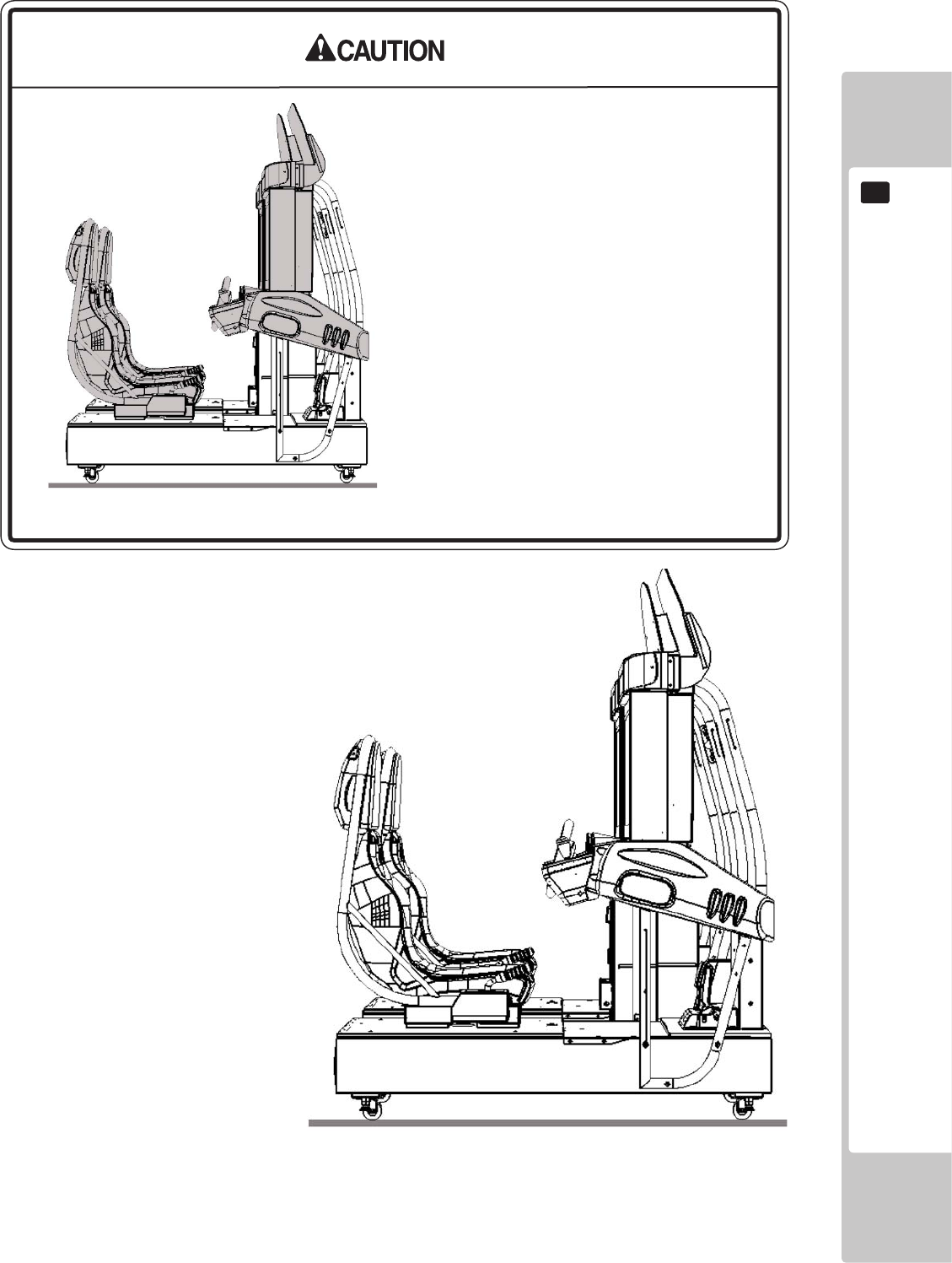
8-3 CAR SELECTION
urningthe‘SteeringWheel’leftandrightwill
changetheScreendisplaytoshowinturneachoftheCarsthatareavailableduringthatRace,
WhenthedesiredCarisdisplayed,theselectionismadebypressingtheAcceleratorpedalorStart
buttontoconrmthechoice.
Duringthisselectionsequence,aCOUNTDOWNisbeingdisplayedinthetoprighthandcornerof
thescreen.Ifthereisnoorlittleinterventionshownbytheplayerduringthistime,whateverGame
ModeisbeingdisplayedonthescreenonTIMEOUTwillautomaticallybeselectedandthegame
willadvancetothenextStage,TYPEOFTRANSMISSION.
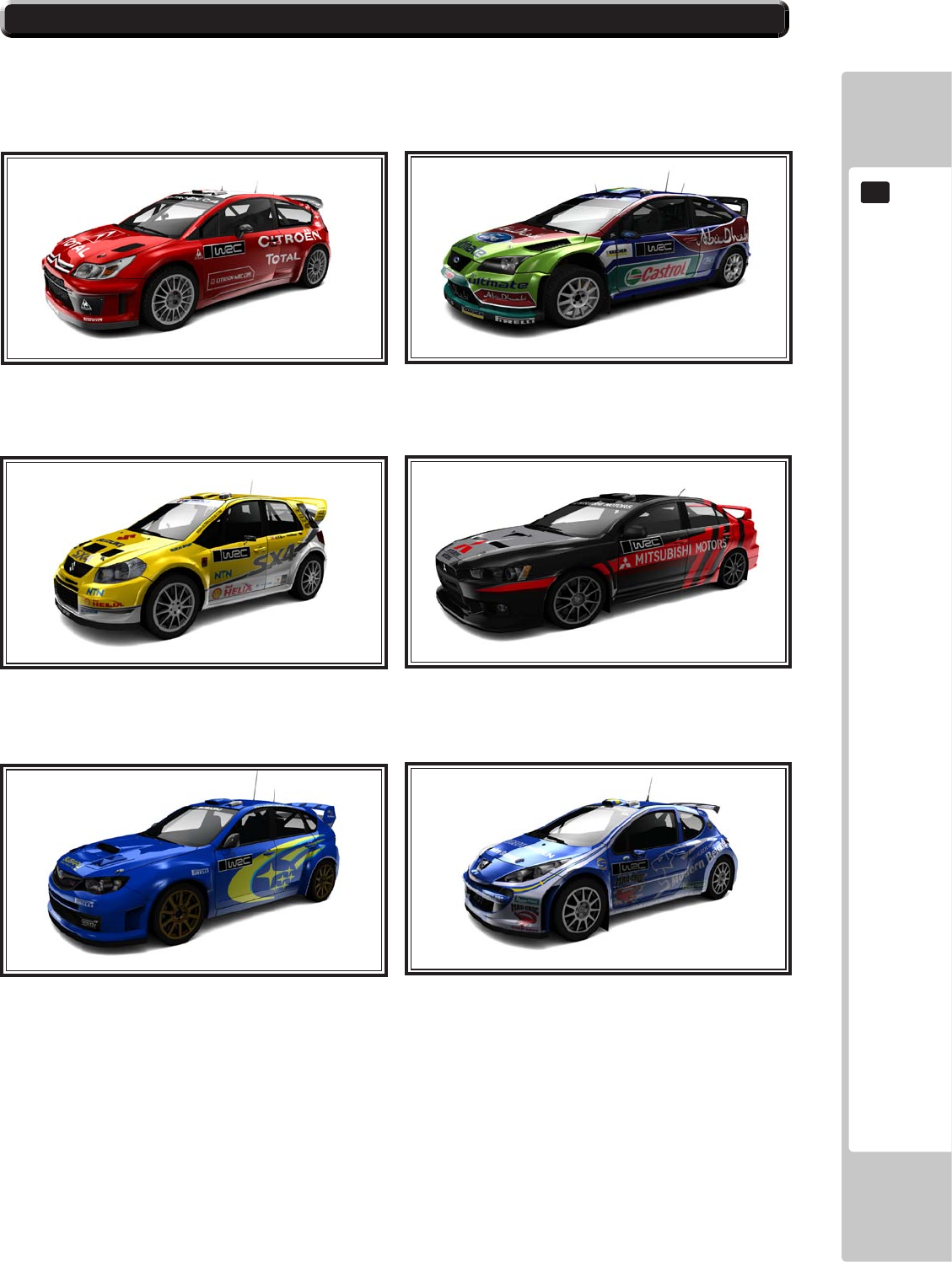
The core set of cars available to the player are a selection of six WRC derived vehicles
8-3 CAR SELECTION

Car Availability by Game Mode
Car Championship Quick Race Classic
8-3 CAR SELECTION

8-4 CAR TRANSMISSION TYPE
Thereisonlytwochoicesavailabletochoosefrom,AUTOMATICTRANSMISSION(Shownabove)or
MANUALTRANSMISSION.TurntheSteeringWheelLeftandRighttoselectbetweenthetwoand
presstheAcceleratororStartButtontoconrmthechoice,
Againthecountdownsystemisinoperationsoifaselectionisnotconrmedthemachinewillselect
whichevertransmissiontypeisdisplayedonthescreenwhentheTimeOutoccurs

TRACK SELECTION
Track/Mode Championship Quick Race Classic
8-5 TRACK SELECTION
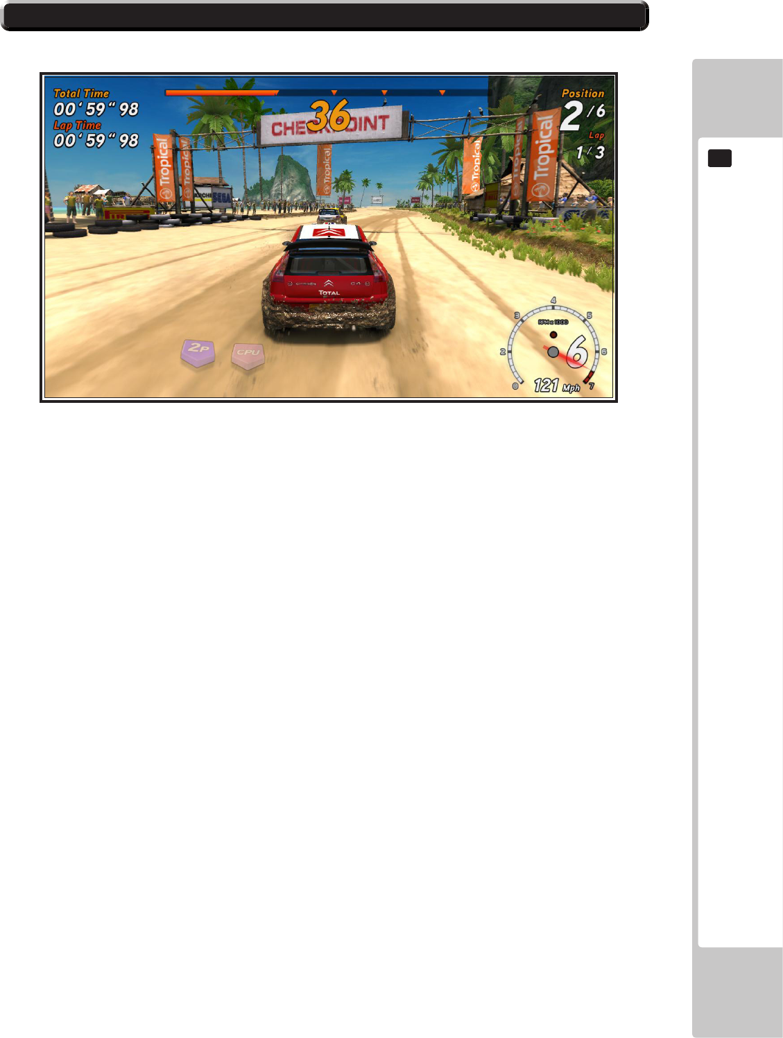
8-6 ON SCREEN DISPLAY
ELEMENT DESCRIPTION
(Link Play only) Appears when checkpoints are crossed -
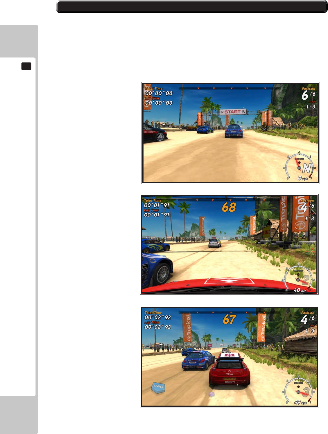
8-7 DRIVERS VIEW - CAMERA POSITION
SEGA Rally 3, features three dierent in-game camera views that
are cycled between when the “Change View” button is pressed.
BUMPER
CAMERA
BONNET
CAMERA
CHASE
CAMERA
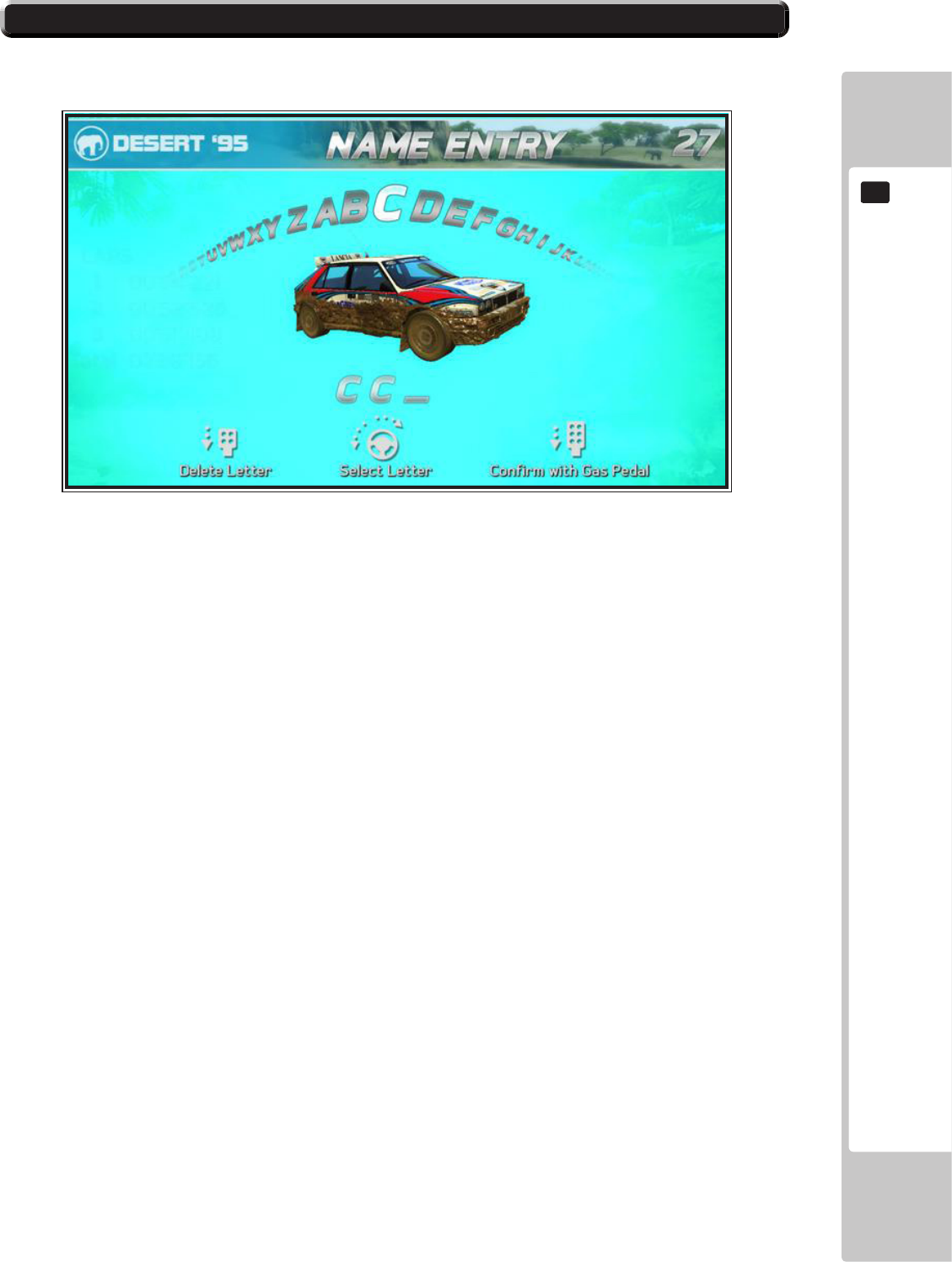
HIGH SCORE TABLES
TO ENTER A NEW RECORD
8-8 HIGH SCORE TABLES
9
TEST MODE
50
• When you enter the Test Mode, fractional coin and bonus adder data is erased.
• Adjust the sound to the optimum volume, taking into consideration the
environmental requirements of the installation location.
• Removing the Coin Meter circuitry renders the game inoperable.
Be careful that a nger or hand does not get caught when opening/closing the coin
chute door.
Never touch places other than those specied. Touching places not specied can cause
electric shock and short circuit accidents.
TESTMODE
9
TEST MODE
9
51
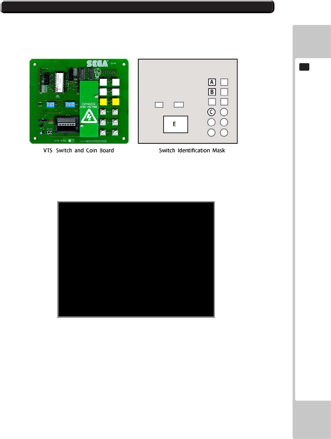
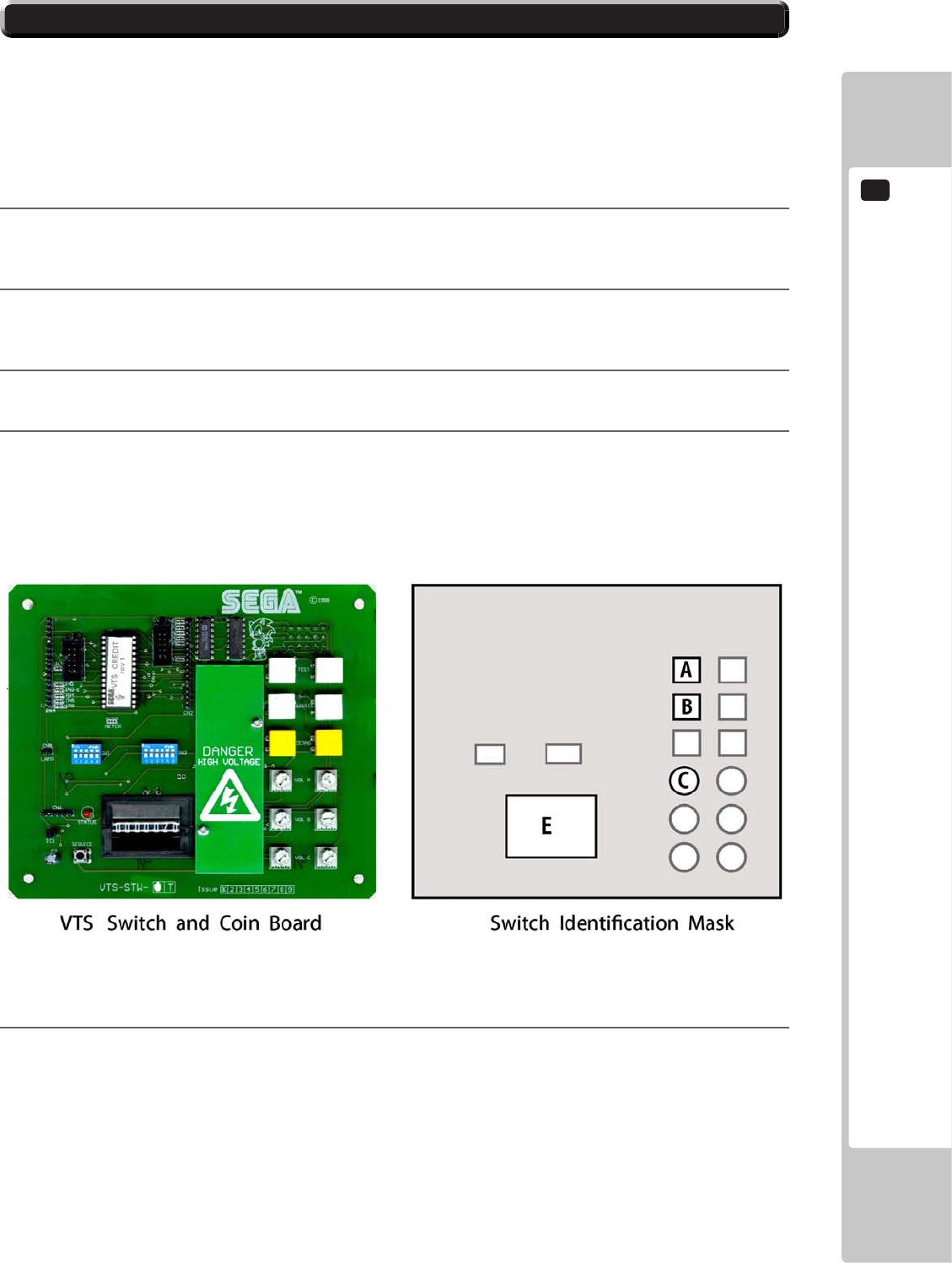
9-1 SWITCH UNIT AND COIN METER
A
TEST BUTTON
B
SERVICE BUTTON
C
MAIN VOLUME
E
9
TEST MODE
52
9-2 GAME TEST MODE
• When changing the Game Conguration, any changes actioned will not take eect
unless the Game Test Mode completes the exit cycle correctly.
• Do not congure the game in ways not described in this text. It is possible that the
game will not function properly.
• Refer to BOOKKEEPING in GAME TEST MODE for this products data.
• Adjust for an appropriate sound volume in consideration of the installation site.
• If the coin meter circuit is removed, play cannot be executed.

TEST MODE
9
53
• Always be sure to exit the Game Test Mode properly after conguration changes
otherwise any changes made will not take eect.
• Do not congure the game in ways not described in this text. It is possible that the
game will not function properly.
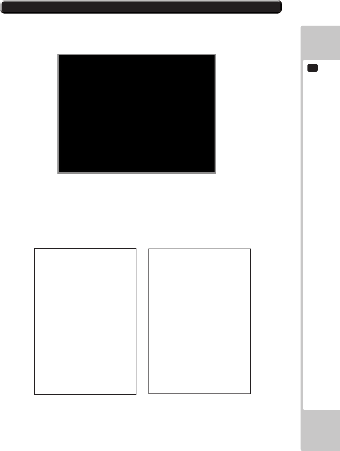
9-2 GAME TEST MODE
9-2 GAME TEST MODE
The following options are available from the System Menu Test
9-2 FIG. 01
PLAYER 1
TEST MENU
SELECT WITH SERVICE BUTTON
AND PRESS TEST BUTTON
SYSTEM INFORMATION
INPUT TEST
OUTPUT TEST
MOTION BASE TEST
COIN SETTINGS
SOUND SETTINGS
SCREEN TEST
NETWORK TEST
CALIBRATE INPUT
BOOKKEEPING
CLOCK SETTINGS
GAME SETTINGS
RESET TO FACTORY DEFAULT
EXIT
>>

9
TEST MODE
54
9-2 GAME TEST MODE
9-2-1 SYSTEM INFORMATION
PLAYER 1
SYSTEM INFORMATION
PRESS TEST BUTTON
TO EXIT
DISK IMAGE VERSION UNKNOWN
LAUNCHER VERSION UNKNOWN
GAMESHELL VERSION 0.2.3
GAME NAME NOT INSTALLED
GAME VERSION NOT INSTALLED
CABINET TYPE UNKNOWN
SECURITY KEY STATUS NOT DETECTED
IO BOARD STATUS NOT DETECTED
MOTION BASE STATUS NOT PRESENT
NETWORK STATUS ENABLED
EXIT
>>

TEST MODE
9
55
9-2 GAME TEST MODE
9-2-2 INPUT TEST
Select‘INPUTTEST’fromthe‘GameTestMode’Menutodisplay‘InputTest’Menu.
PLAYER 1
INPUT TEST
PRESS TEST AND SERVICE BUTTON
TO EXIT
STEERING : 0000
BRAKE : 0000
ACCELERATOR : 0000
START BUTTON : OFF
VIEW BUTTON : OFF
HANDBRAKE : OFF
GEARSHIFT UP : OFF
GEARSHIFT DOWN : OFF
MOTION STOP : OFF
MOTION LIMIT L TOP : OFF
MOTION LIMIT L BOTTOM : OFF
MOTION LIMIT R TOP : OFF
MOTION LIMIT R BOTTOM : OFF
TEST BUTTON : OFF
SERVICE BUTTON : OFF
COIN INPUT : OFF
EXIT
>>

9
TEST MODE
56
9-2 GAME TEST MODE
9-2-3 OUTPUT TEST
Select‘OUTPUTTEST’fromthe‘GameTestMode’Menutodisplay‘OutputTest’Menu..
PLAYER 1
OUTPUT TEST
SELECT WITH SERVICE BUTTON
AND PRESS TEST BUTTON
START LAMP OFF
VIEW LAMP OFF
RACE LEADER LAMP OFF
HEADLIGHTS OUTER LAMPS OFF
HEADLIGHTS INNER LAMPS OFF
REAR LIGHTS OUTER LAMPS OFF
REAR LIGHTS INNER LAMPS OFF
MOTION STOP LAMP OFF
RED LINE LAMP OFF
BLUE LINE LAMP OFF
EXIT
>>
TEST MODE
9
57
9-2-4 COIN SETTINGS
Select‘COINSETTING’fromthe‘GameTestMode’Menutodisplay‘CoinSettings’Menu..
1
2
3
5
6
7
8
9
10
11
12
13
14
15
16
PLAYER 1
COIN SETTINGS
SELECT WITH SERVICE BUTTON
AND PRESS TEST BUTTON
COIN COUNT 0000
CREDITS 0000
SERVICE CREDITS 0000
CREDIT SETTING SETTING #1
1 COIN 1 CREDIT
EXIT
>>
9-2 GAME TEST MODE

9
TEST MODE
58
9-2-5 SOUND SETTINGS
PLAYER 1
SOUND SETTINGS
SELECT WITH SERVICE BUTTON
AND PRESS TEST BUTTON
ATTRACT SOUND OFF
MUSIC VOLUME 85
EFFECT VOLUME 75
VOICE VOLUME 60
TEST MUSIC OFF
TEST EFFECT OFF
TEST VOICE OFF
TEST FRONT SPEAKERS OFF
TESR REAR SPEAKERS OFF
TEST WOOFER OFF
EXIT
>>
9-2 GAME TEST MODE

TEST MODE
9
59
9-2-6 SCREEN TEST
Select‘SCREENTEST’fromthe‘GameTestMode’Menutodisplay‘ScreenTest’Menu..
COLOURBARS
PLAYER 1
SCREEN TEST
SELECT WITH SERVICE BUTTON
AND PRESS TEST BUTTON
COLOUR BARS
BRIGHTNESS
GRID ALIGNMENT
EXIT
>>
YELLOW CYAN GREEN PURPLE RED BLUE BLACK
WHITE
9-2 GAME TEST MODE

9
TEST MODE
60
9-2-6 SCREEN TEST (Continued)
BRIGHTNESS
GRIDALIGNMENT
9-2 GAME TEST MODE

TEST MODE
9
61
9-2-7 NETWORK TEST
Select‘NETWORKTEST’fromthe‘GameTestMode’Menutodisplaythe‘NetworkTest’Menu..
PLAYER 1
NETWORK SETTINGS
SELECT WITH SERVICE BUTTON
AND PRESS TEST BUTTON
NETWORK STATUS ON
CABINET CONNECTED 0
NETWORK ENABLED YES
CABINET ID 1
CONFIRM CHANGES
EXIT
>>
9-2 GAME TEST MODE

9
TEST MODE
62
9-2-8 CALIBRATE INPUTS 1/2
Select‘CALIBRATEINPUTS’fromthe‘GameTestMode’Menutodisplaythe‘CalibrateInputs’Menu..
CALIBRATION SET PROCEDURE CONTINUED ON NEXT PAGE
PLAYER 1
CALIBRATION TEST
SELECT WITH SERVICE BUTTON
AND PRESS TEST BUTTON
STEERING LEFT 0
STEERING RIGHT 255
BRAKE UP 0
BRAKE DOWN 255
ACCELERATOR UP 0
ACCELERATOR DOWN 255
STEERING OUTPUT OFF
STEERING STRENGHT STRONG
SEAT MOTION STRENGHT STRONG
CALIBRATE STEERING
CALIBRATE BRAKE
CALIBRATE ACCELERATOR
EXIT
>>
9-2 GAME TEST MODE

TEST MODE
9
63
9-2-8 CALIBRATE INPUTS (Continued) 2/2
Select‘CALIBRATEINPUTS’fromthe‘GameTestMode’Menutodisplaythe‘CalibrateInputs’Menu..
PLAYER 1
CALIBRATION TEST
SELECT WITH SERVICE BUTTON
AND PRESS TEST BUTTON
STEERING LEFT 0
STEERING RIGHT 255
BRAKE UP 0
BRAKE DOWN 255
ACCELERATOR UP 0
ACCELERATOR DOWN 255
STEERING OUTPUT OFF
STEERING STRENGHT STRONG
SEAT MOTION STRENGHT STRONG
CALIBRATE STEERING
CALIBRATE BRAKE
CALIBRATE ACCELERATOR
EXIT
>>
9-2 GAME TEST MODE

9
TEST MODE
64
9-2-9 BOOK KEEPING 1/7
Select‘BOOKKEEPING’fromthe‘GameTestMode’Menutodisplay‘Bookkeeping’Menu..
PLAYER 1
BOOKKEEPING PAGE 1/7 SUMMARY
SELECT WITH SERVICE BUTTON
AND PRESS TEST BUTTON
TOTAL TIME ON 0:56’36’
TOTAL CREDITS IN 0
TOTAL CREDIT CONTINUES 0
TOTAL SERVICE CREDITS 0
TOTAL SERVICE CREDIT CONTINUES 0
TOTAL PLAYS 121
TOTAL AVERAGE GAME TIME 00’00”
TRANSMISSION MANUAL 17
TRANSMISSION AUTO 99
BOOKKEEPING LAST CLEARED 00/00/0000 00.00
HIGH SCORED LAST CLEARED 00/00/0000 00.00
CLEAR HIGH SCORE
CLEAR BOOKKEEPING
NEXT PAGE
EXIT
>>
9-2 GAME TEST MODE

TEST MODE
9
65
9-2-9 BOOK KEEPING (Continued) 2-3 / 7
Bookkeeping – Screen 2 DATA ON ‘TOTAL PLAYS’
Bookkeeping – Screen 3 DATA ON ‘AVERAGE GAME TIMES’
PLAYER 1
BOOKKEEPING PAGE 2/7 PLAYS
SELECT WITH SERVICE BUTTON
AND PRESS TEST BUTTON
TOTAL PLAYS 0
TOTAL PLAYS CHAMPIONSHIP 0 (0%)
TOTAL PLAYS QUICK RACE SP 0 (0%)
TOTAL PLAYS CLASSIC SP 0 (0%)
TOTAL PLAYS QUICK RACE MP 0 (0%)
TOTAL PLAYS CLASSIC MP 0 (0%) 121
NEXT PAGE
EXIT
>>
PLAYER 1
BOOKKEEPING PAGE 3/7 GAME TIMES
SELECT WITH SERVICE BUTTON
AND PRESS TEST BUTTON
TOTAL AVERAGE GAMR TIME 0’00”
AVERAGE GAME TIME SINGLE PLAYER 0’00”
AVERAGE GAME TIME MULTIPLAYER 0’00” 121
AVERAGE GAME TIME CHAMPIONSHIP 0’00”
AVERAGE GAME TIME QUICK RACE SP 0’00”
AVERAGE GAME TIME CLASSIC SP 0’00”
AVERAGE GAME TIME QUICK RACE MP 0’00”
AVERAGE GAME TIME CLASSIC MP 0’00”
NEXT PAGE
EXIT
>>
9-2 GAME TEST MODE

9
TEST MODE
66
9-2-9 BOOK KEEPING (Continued) 4-5 / 7
Bookkeeping – Screen 4 DATA ON ‘DAYS OF PLAY’
Bookkeeping – Screen 5 DATA ON ‘TIMES OF PLAY’
PLAYER 1
BOOKKEEPING PAGE 4/7 PLAYS BY DAY
SELECT WITH SERVICE BUTTON
AND PRESS TEST BUTTON
PLAYS ON SUNDAY 0
PLAYS ON MONDAY 0
PLAYS ON TUESDAY 0
PLAYS ON WEDNESDAY 0
PLAYS ON THURSDAY 0
PLAYS ON FRIDAY 0
PLAYS ON SATURDAY 0
NEXT PAGE
EXIT
>>
PLAYER 1
BOOKKEEPING PAGE 5/7 PLAYS BY TIME
SELECT WITH SERVICE BUTTON
AND PRESS TEST BUTTON
00-01 0 12-13 0
01-02 0 13-14 0
02-03 0 14-15 0
03-04 0 15-16 0
04-05 0 16-17 0
05-06 0 17-18 0
06-07 0 18-19 0
07-08 0 19-20 0
08-09 0 20-21 0
09-10 0 21-22 0
10-11 0 22-23 0
11-12 0 23-24 0
NEXT PAGE
EXIT
>>
9-2 GAME TEST MODE

TEST MODE
9
67
9-2-9 BOOK KEEPING (Continued) 6-7 / 7
Bookkeeping – Screen 6 DATA ON ‘RACE TRACKS’
Bookkeeping – Screen 7 ‘DATA ON CARS’
PLAYER 1
BOOKKEEPING PAGE 6/7 TRACKS
SELECT WITH SERVICE BUTTON
AND PRESS TEST BUTTON
TROPICAL 0
CANYON 0
ALPINE 0
DESERT 95 0
NEXT PAGE
EXIT
>>
PLAYER 1
BOOKKEEPING PAGE 7/7 CARS
SELECT WITH SERVICE BUTTON
AND PRESS TEST BUTTON
Citroen C4 WRC 0
Ford Focus RS WRC 07 0
Subaru Impreza WRC2008 0
Suzuki SX4 WRC 0
Mitsubishi Lancer Evolution X 0
Peugeot 207 Super 2000 0
Toyota Celica ST205 0
Lancia Super Delta HF integrale 0
Bowler Nemesis 0
McRae Enduro 0
NEXT PAGE
EXIT
>>
9-2 GAME TEST MODE

9
TEST MODE
68
9-2-10 CLOCK SETTINGS
Select‘CLOCKSETTINGS’fromthe‘GameTestMode’Menutodisplay‘ClockSettings’Menu..
PLAYER 1
CLOCK SETTINGS
SELECT WITH SERVICE BUTTON
AND PRESS TEST BUTTON
CURRENT TIME 09:54:37
CURRENT DATE 30/04/2008
YEAR 2008
MONTH 04
DATE 30
HOURS 09
MINUTES 54
SECONDS 37
EXIT
>>
9-2 GAME TEST MODE

TEST MODE
9
69
9-2-11 GAME SETTINGS
Select‘GAMESETTINGS’fromthe‘GameTestMode’Menutodisplay‘GameSettings’Menu..
PLAYER 1
GAME SETTINGS
SELECT WITH SERVICE BUTTON
AND PRESS TEST BUTTON
SPEEDO MPH
VIEW BONNET
LANGUAGE ENGLISH
DIFFICULTY MEDIUM
CONTINUES ON
RACE LENGTH 3
EXIT
>>
9-2 GAME TEST MODE
70
CONTROL UNIT
10
CONTROLLER UNIT
10
CONTROL UNIT
71
10
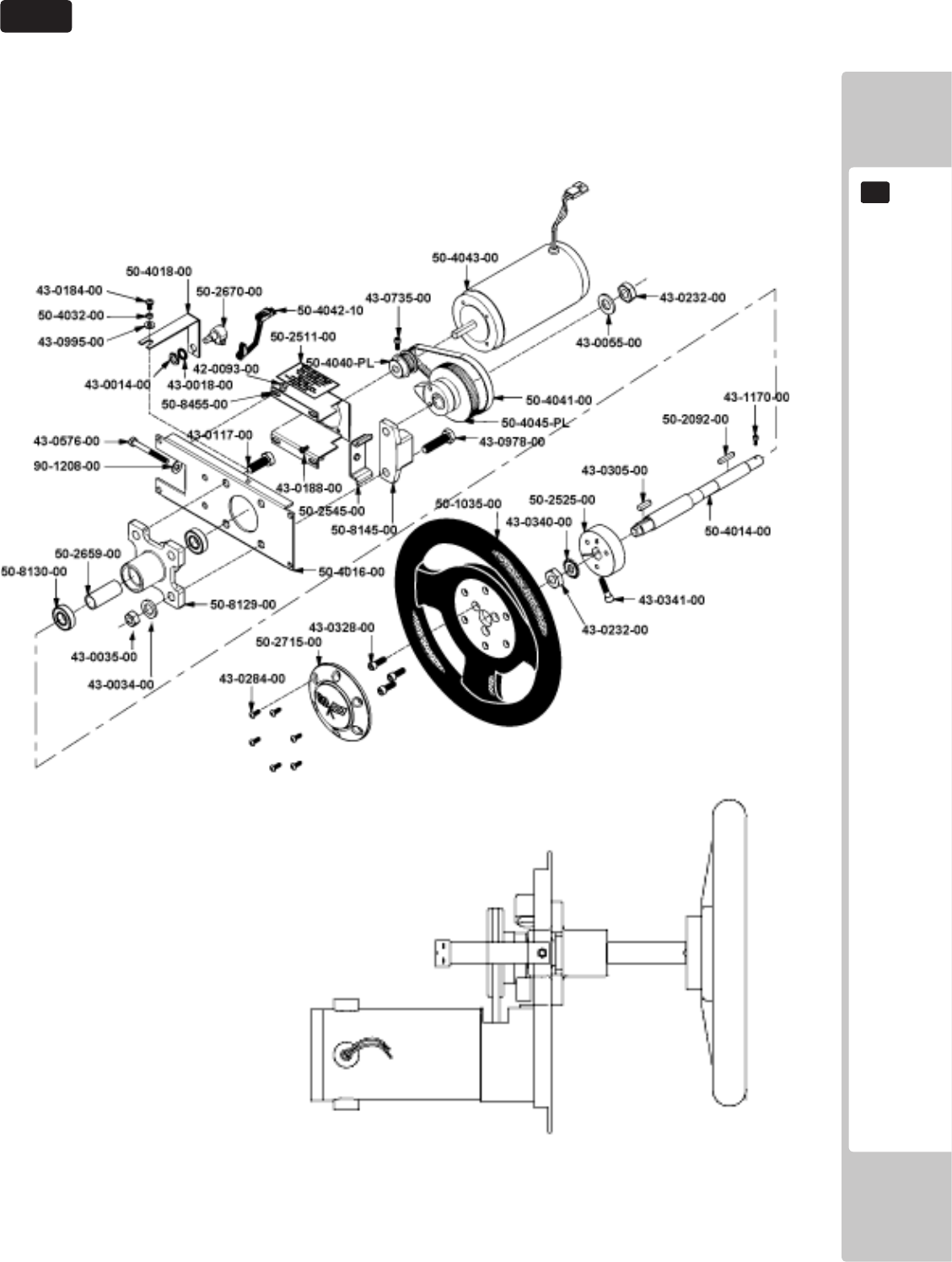
STEERING WHEEL ASSEMBLY
10.1
72
CONTROL UNIT
10
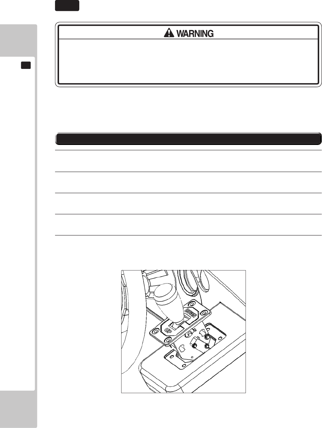
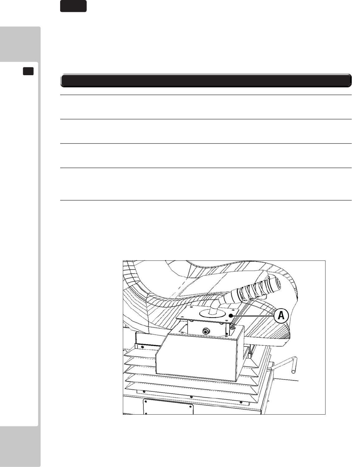
If the shift lever switch input does not function correctly on the INPUT TEST screen, the switch may
need to be replaced. To carry out this maintenance, you must rst remove the shift lever unit.
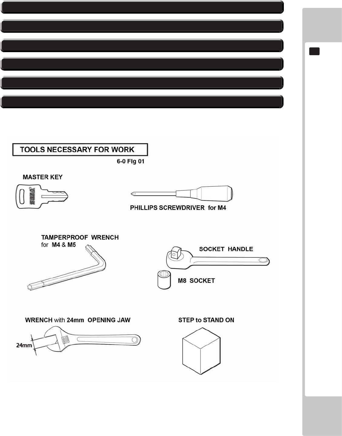
For this task, you will need a tamper proof wrench (for M5 screws), /and a Phillips-head screwdriver (for
M4 screws).
1
Turn the power OFF
2
Using the M5 tamper proof wrench remove the four tamper proof screws, 1 located in each of
the corner of the Shift Lever.
3
Gently lift out the Shift Lever to reveal the wiring harness, locate the plug connecting it to the
Control panel and remove the connection.The Shift Lever can now be extracted.
4
When re-installing the Shift Lever follow the above instructions in the reverse order. At this
time ensure that the ‘DOWN’ display appears on the upper part of the Shift Lever as shown.
5
After the Re-installation of the Shift Lever, be sure to check the INPUT TEST in the Game Test
mode to determine it’ s correct operation.
SHIFT LEVER
10.2
● When working with the product, be sure to turn the power o. Working with the
power on may cause an electric shock or short circuit.
● Be careful not to damage the wires. Damaged wires may cause an electric shock,
short circuit or present a risk of re.
10-21 REMOVING THE SHIFT LEVER
CONTROL UNIT
73
10
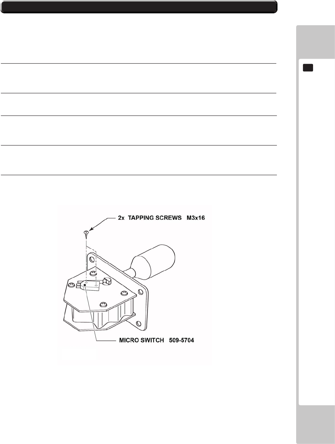
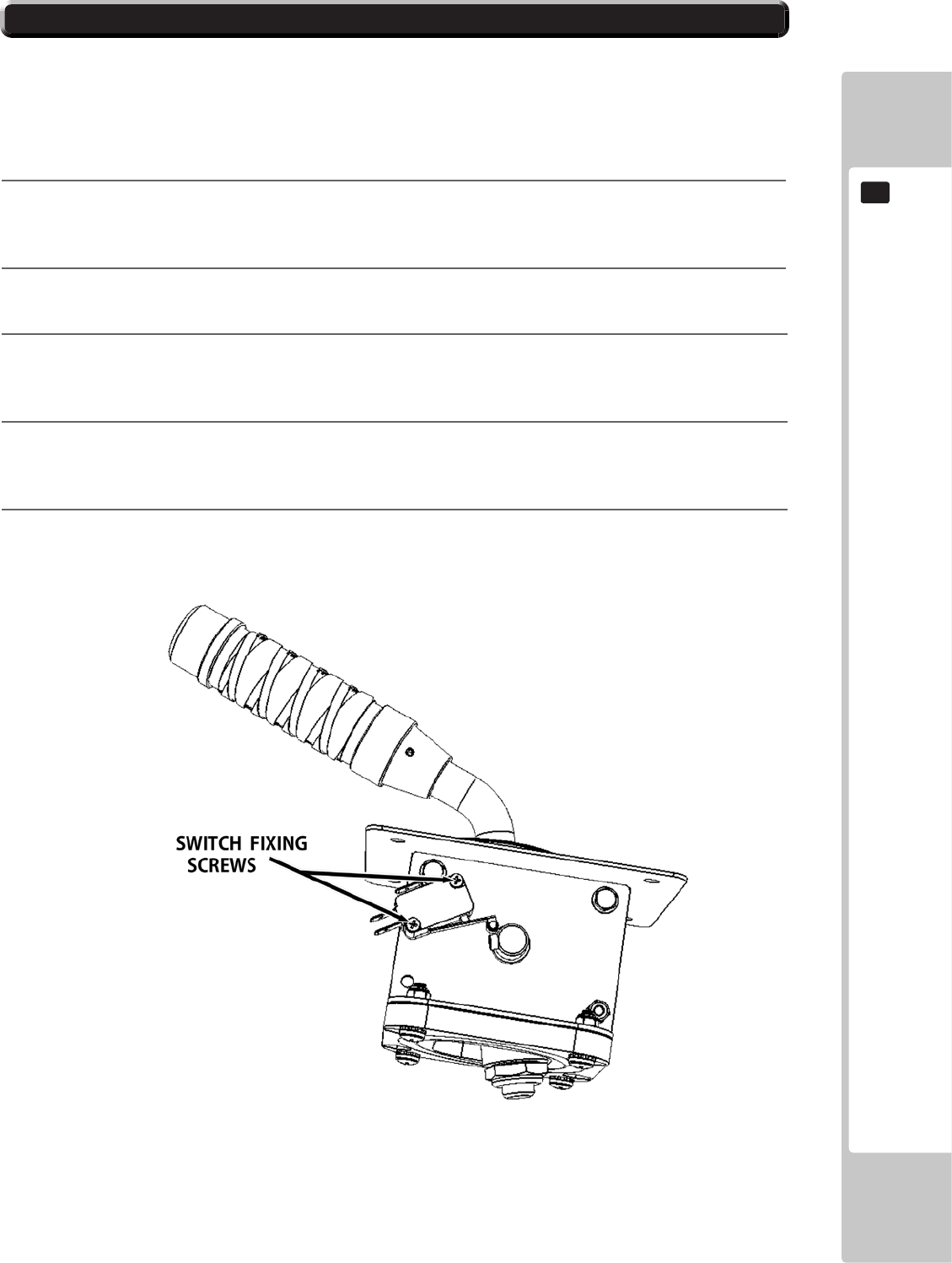
Follow the instructions below to change the microswitch.
1
Unscrew and remove the M3x16 Self Tapping Screws which secure the microswitch to the
Gear Shift base.
2
Remove the microswitch.
3
Remove the wiring harness from the old miscoswitch and re-attach it to the replacement
switch in the same manner
4
Using the M3x10 self tapping screws, ret the replacement microswitch to the Gear Shift
base.
5
The unit is now ready to be retted into the control panel, to do this follow in the reverse order
11-1 Removing the Shift Level.
10.22 SWITCH REPLACEMENT
74
CONTROL UNIT
10
If the accelerator or brake pedals are not functioning correctly, you may need to adjust the position-
ing of the volume or replace it with a new one. In addition, you should apply grease to the gear con-
tacts and spring parts once every three months.
ACCELERATOR & BRAKE
10.3
● When working with the product, be sure to turn the power o. Working with the
power on may cause an electric shock or short circuit. However, the unit must be
switched on when using test mode. Do not touch any part of the unit except those
areas indicated.
● Be careful not to damage the wires. Damaged wires may cause an electric shock,
short circuit or present a risk of re.
● This work should be performed by site maintenance personnel or other skilled
professionals. Work performed by non-technical personnel can cause a severe
accident such as an electric shock.
● To prevent accidents while working or while operating the product after it has
been installed, be sure not to conduct any procedures other than those given in
this manual. There are cases in which procedures not covered in this manual
require special tools and skills. If a procedure not given in this manual is required,
request service from the oce given in this manual or from the point of purchase.
Be sure to perform volume's move value setting in the Input Test in the Game Test
Mode after replacing or adjusting the Volume.
CONTROL UNIT
75
10
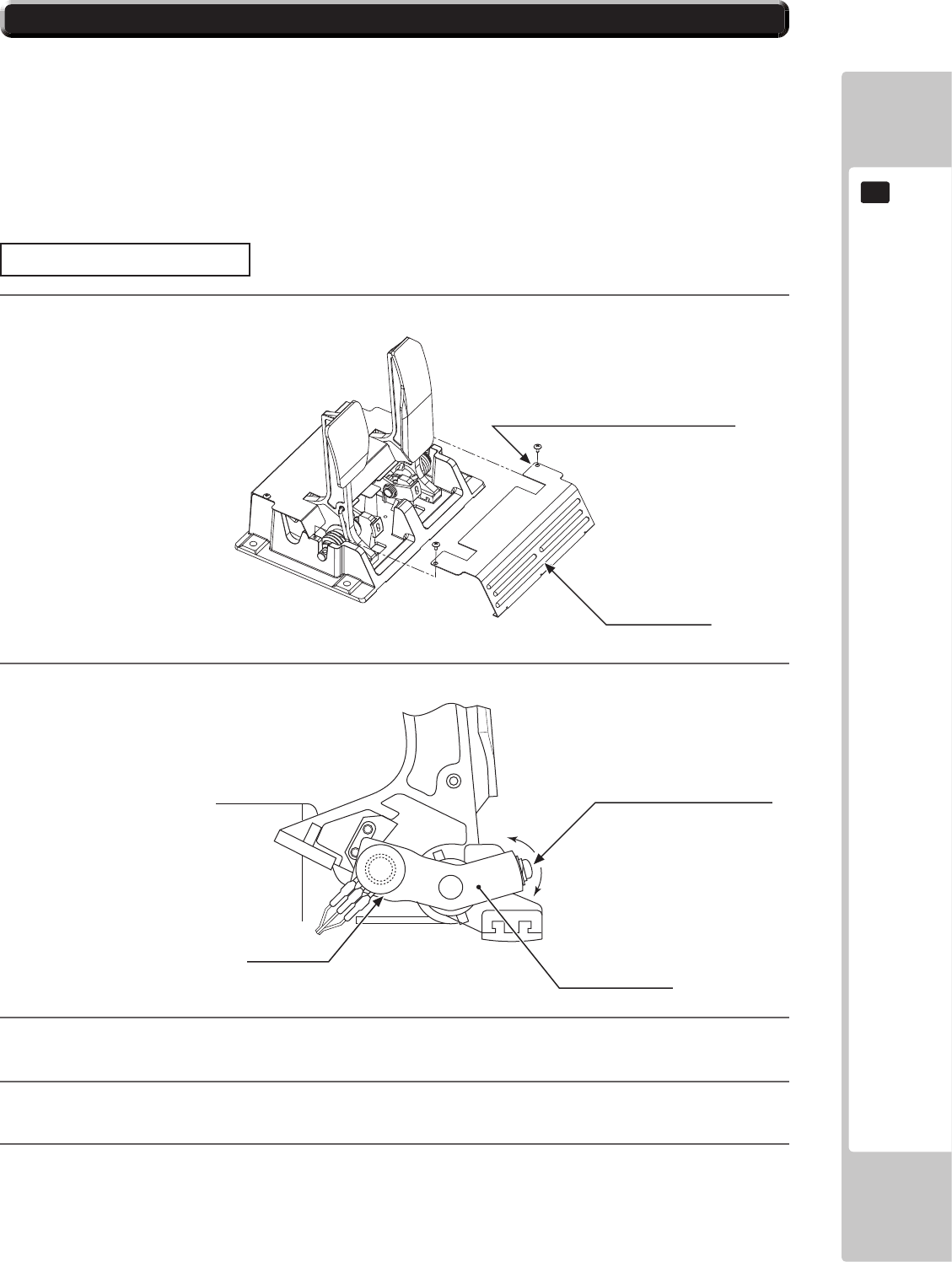
Adjusting Procedure
1
.
2
Loosenthesinglescrewthatsecuresthepotentiobase,andmovethebasetoadjustthevolume
values.
3
Securethepotentiobase.
4
CongurethevolumevaluesontheINPUTASSIGNMENTSscreeninGameTestMode(seeService
Manual).
5
Checkthatthevalueschangesmoothlyinresponsetopedalinput.
10-31 ADJUSTING/REPLACING THE VOLUME
TRUSS SCREW (2), chrome
M4x8
FRONT COVER
SCREW (1)
M5x12, w/at & spring washers
POTENTIOBASE
VOLUME
220-5484
220-5753
76
CONTROL UNIT
10
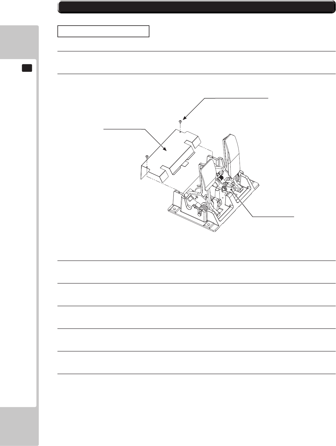
Replacing the Volume
1
Switchotheunit.
2
Removethetwoscrewsandliftothepotentiocover.
3
Detachtheconnectorfromthevolumetobereplaced.
4
Removethesinglescrewthatsecuresthepotentiobase.(see10-31FIG.02).
5
Withoutdetachingthevolume,removethepotentiobase.(see10-31FIG.03).
6
Removethebaseandgearfromthevolume,andreplaceit.
7
Afterreplacement,congurethevolumeasdescribedabovein“AdjustingProcedure”
8
Whenyouhavenished,checkthatthevalueschangesmoothlyinresponsetopedalinput.
10-31 ADJUSTING/REPLACING THE VOLUME
TRUSS SCREW (2), chrome
M4x8
POTENTIO COVER
POTENTIOBASE
CONTROL UNIT
77
10
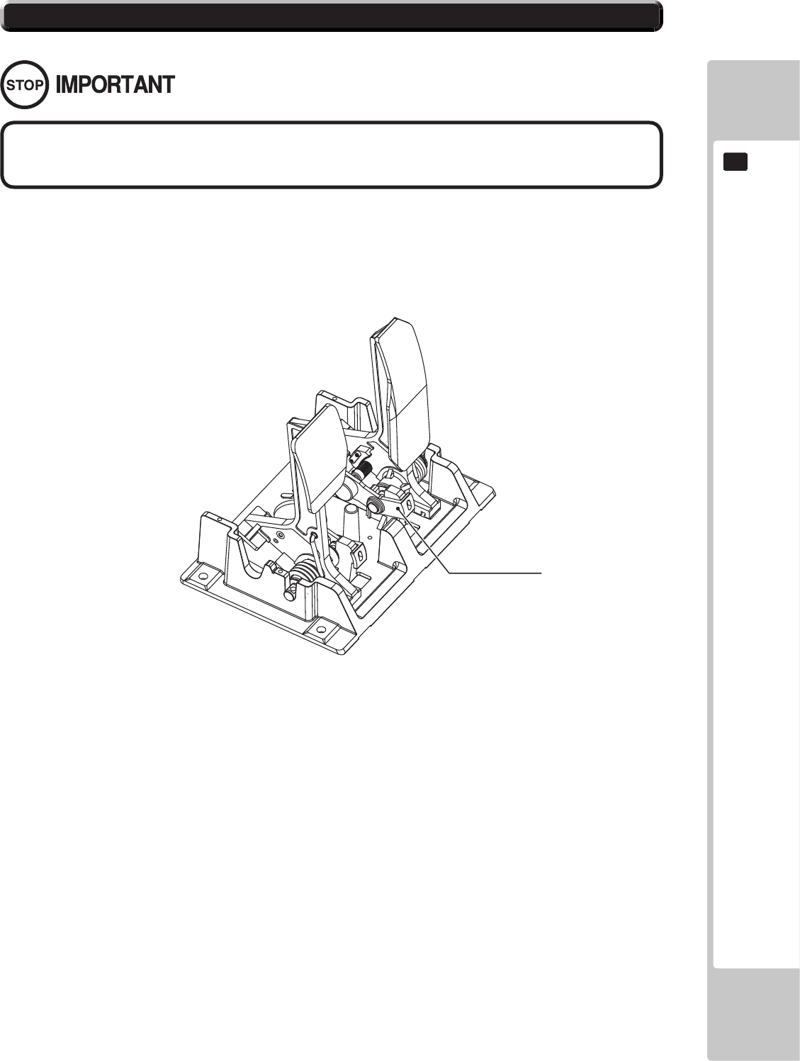
10-32 GREASING
Use only the specied grease. Using any other kind of grease can result in damage to
parts.
POTENTIOBASE
78
CONTROL UNIT
10
HAND BRAKE ASSEMBLY
10.4
1
Turn the power OFF
2
Using the M5 tamper proof wrench remove the four tamper proof screws, 1 located in each of
the corner of the Hand Brake Lever Plate. Marked 'A'
3
Gently lift out the Hand Brake Lever to reveal the wiring harness, locate the plug connecting it
to the Control panel and remove the connection.The Hand Brake can now be extracted.
4
When re-installing the Hand Brake Lever follow the above instructions in the reverse order.
At this time ensure that the ‘DOWN’ display appears on the upper part of the Shift Lever as
shown.
5
After the Re-installation of the Shift Lever, be sure to check the INPUT TEST in the Game Test
mode to determine it’ s correct operation.
If the Hand Brake lever switch input does not function correctly on the INPUT TEST screen, the switch
may need to be replaced. To carry out this maintenance, you must rst remove the Hand brake lever
unit. For this task, you will need a tamper proof wrench (for M5 screws), /and a Phillips-head screw-
driver (for M4 screws).
10-41 REMOVING HAND BRAKE
CONTROL UNIT
79
10
Follow the instructions below to change the microswitch.
1
Unscrew and remove the M3x16 Self Tapping Screws which secure the microswitch to the
Gear Shift base.
2
Remove the microswitch.
3
Remove the wiring harness from the old miscoswitch and re-attach it to the replacement
switch in the same manner
4
Using the M3x10 self tapping screws, ret the replacement microswitch to the Hand Brake
base.
5
The unit is now ready to be retted into the control panel, to do this follow in the reverse order
10-41 Removing the Hand Brake Lever.
10.42 SWITCH REPLACEMENT

80
CONTROL UNIT
10
NOTES ON CONTROL UNITS
MONITOR (32” LCD)
11
Responding to breakdown or abnormality
● If smoke or a strange odor appears, immediately unplug the power cable from the
power source.
Continuing to use the product may cause a re or an electric shock. Ensure that
smoke is no longer emitted, and contact the point of purchase.
● If nothing displays on the screen, immediately unplug the power cable from the
power source.
Continuing to use the product may cause a re or an electric shock. Contact the
point of purchase and request an inspection.
● If water or a foreign object enters the monitor’ s interior, immediately unplug the
power cable from the power source.
Continuing to use the product may cause a re or an electric shock. Contact the
point of purchase and request an inspection.
● If the monitor is dropped or the cabinet is damaged, immediately unplug the
power cable from the power source.
Continuing to use the product may cause a re or an electric shock. Contact the
point of purchase and request an inspection.
During operation
● Do not repair, reconstruct, or disassemble the monitor.
The monitors interior contains high voltage parts. A re or an electric shock
could result.
For inspections, adjustments, and repair of the monitors interior, request work
from the point of purchase.
● Do not insert foreign objects.
If metal objects or ammable materials such as paper are inserted into the interior
through ventilation openings or other apertures, an electric shock could result.
● In the event of a thunder storm, do not touch the product or the power cable. An
electric shock could result.
● Make sure to perform appropriate adjustments. Do not operate the product when
the screen is ickering, distorted, or experiencing other abnormalities. Images
from an improperly adjusted screen could cause players and other customers to
experience dizziness, headaches, and other ailments.
11-1 SAFETY PRECAUTIONS WHEN HANDLING THE MONITOR
CLEANTHESCREENSURFACEONCEAWEEK.
11-2 CLEANING THE SCREEN SURFACE
● Use a soft, dry cloth (annel-type) to wipe away dirt. Do not use materials such as
coarse mesh gauze.
● Alcohol (ethanol) is the recommended solvent for removing dirt. When using a
cleaning agent, follow the precautions below.
- Dilute neutral cleaning agents for home use with water. Soak a soft cloth in the
solution, and wring it thoroughly before wiping the screen.
- Do not use abrasive cleaning agents or powders, or cleaning agents containing
bleach.
- Do not use alkaline cleaning agents such as glass cleaners, or solvents such as
thinners.
● Do not scrub or scratch the screen surface with abrasive materials such as brushes
or scrub brushes.
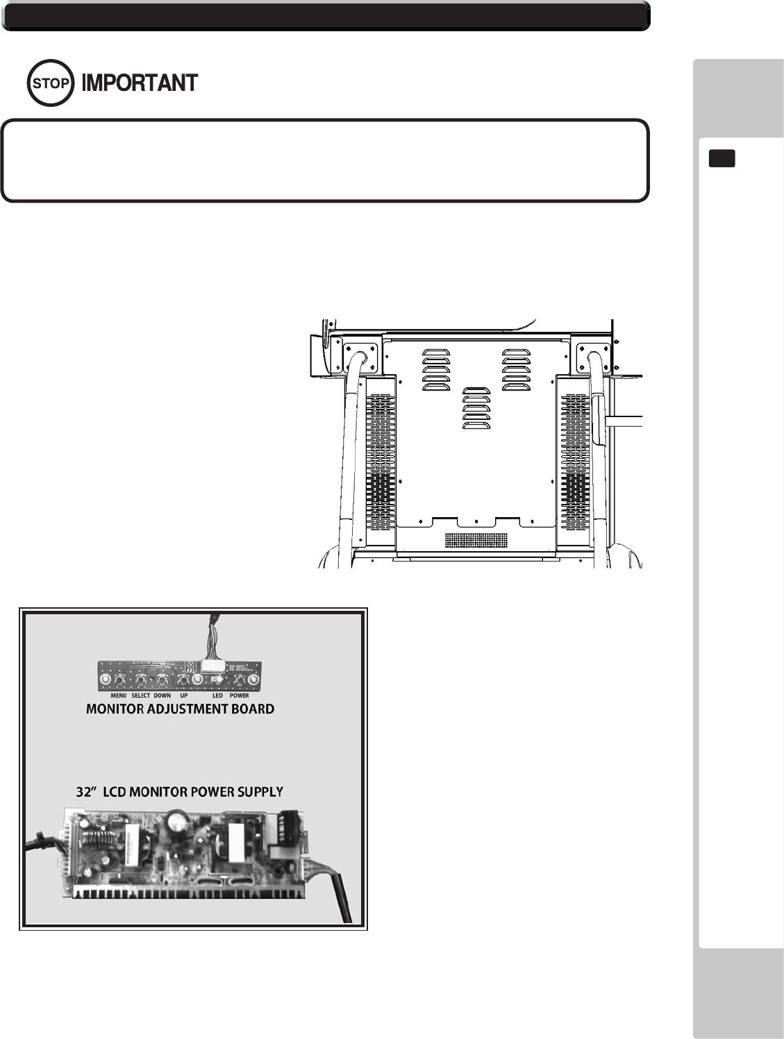
11-3 ADJUSTMENT METHOD
All adjustment values are set accurately at the time of shipping from the factory. Do
not readjust these values needlessly or apply adjustments not specied in this manual.
The display may not appear properly if the values are incorrect.
CONTROL - ADJUSTMENT PROCEDURE
X X
X X
X X
X X X
11-3 Fig. 01
11-3 Fig. 02
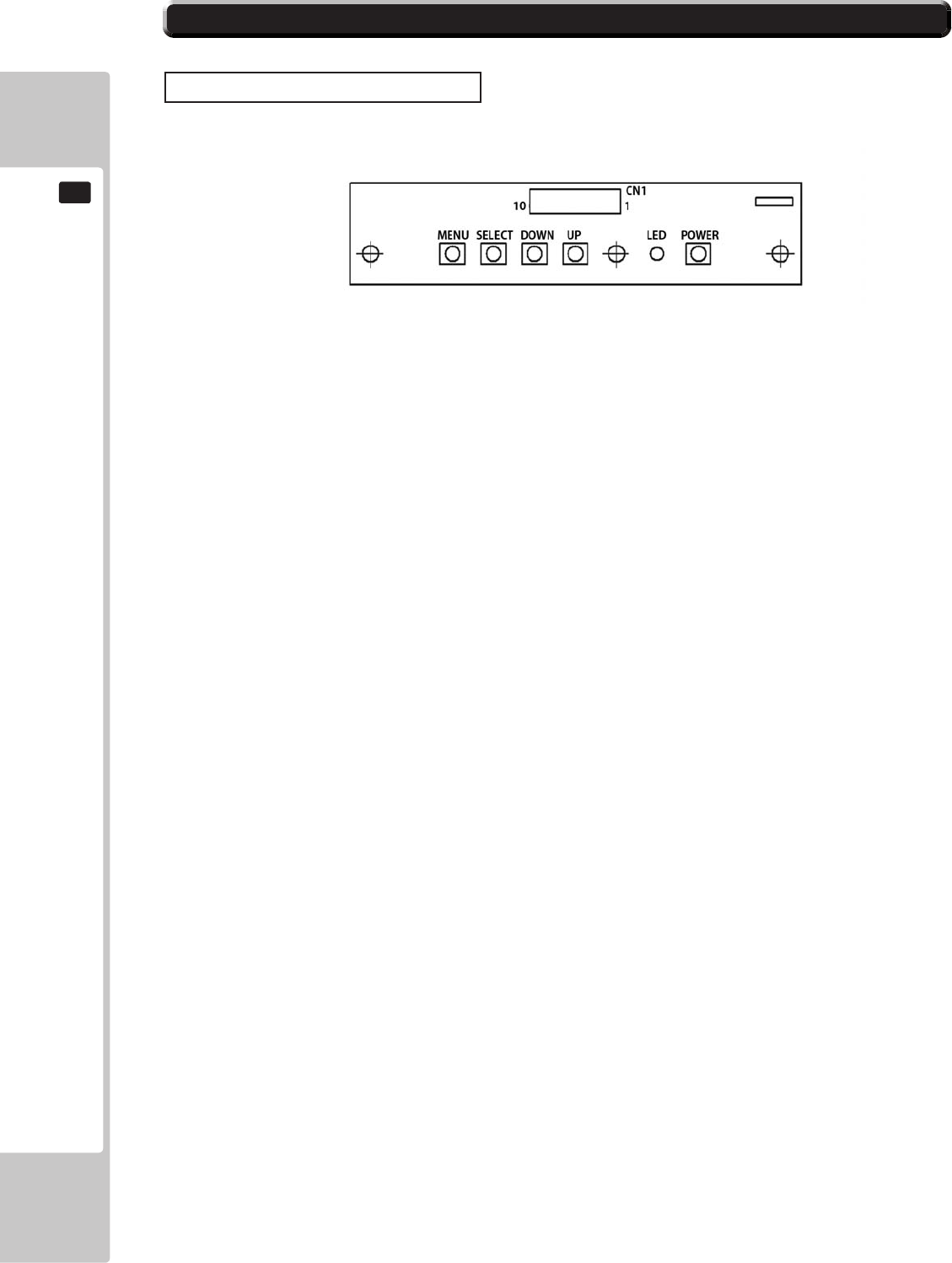
11-3 ADJUSTMENT METHOD
Button Names and Functions
MENU:
Turn the Picture Menu display ON and OFF.
SELECT:
Gains entry to the Item selected in the menu. (Highlights in Yellow when selected)
Exits the Item adustment. Any changes made during this operation are actioned.
DOWN:
Moves the cursor (Black Bar) down to select a menu item.
Decrease the value of, or change, a selected menu item.
UP:
Move the cursor (Black Bar) up to select a menu item.
Increase the value of, or change, a selected menu item.
LED:
LED illuminates green: Monitor is operating.
LED ashes red: Power is o.
POWER:
Turns the LCD Display ON and OFF. (Usually, it’ s not necessary to operate.)
11-3 Fig. 03
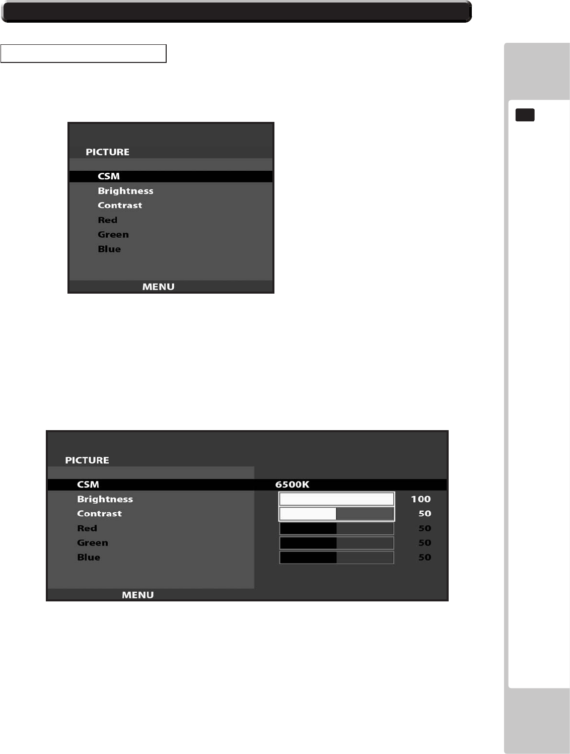
11-3 ADJUSTMENT METHOD
On-Screen Display (OSD)
11-3 Fig. 04
11-3 Fig. 05
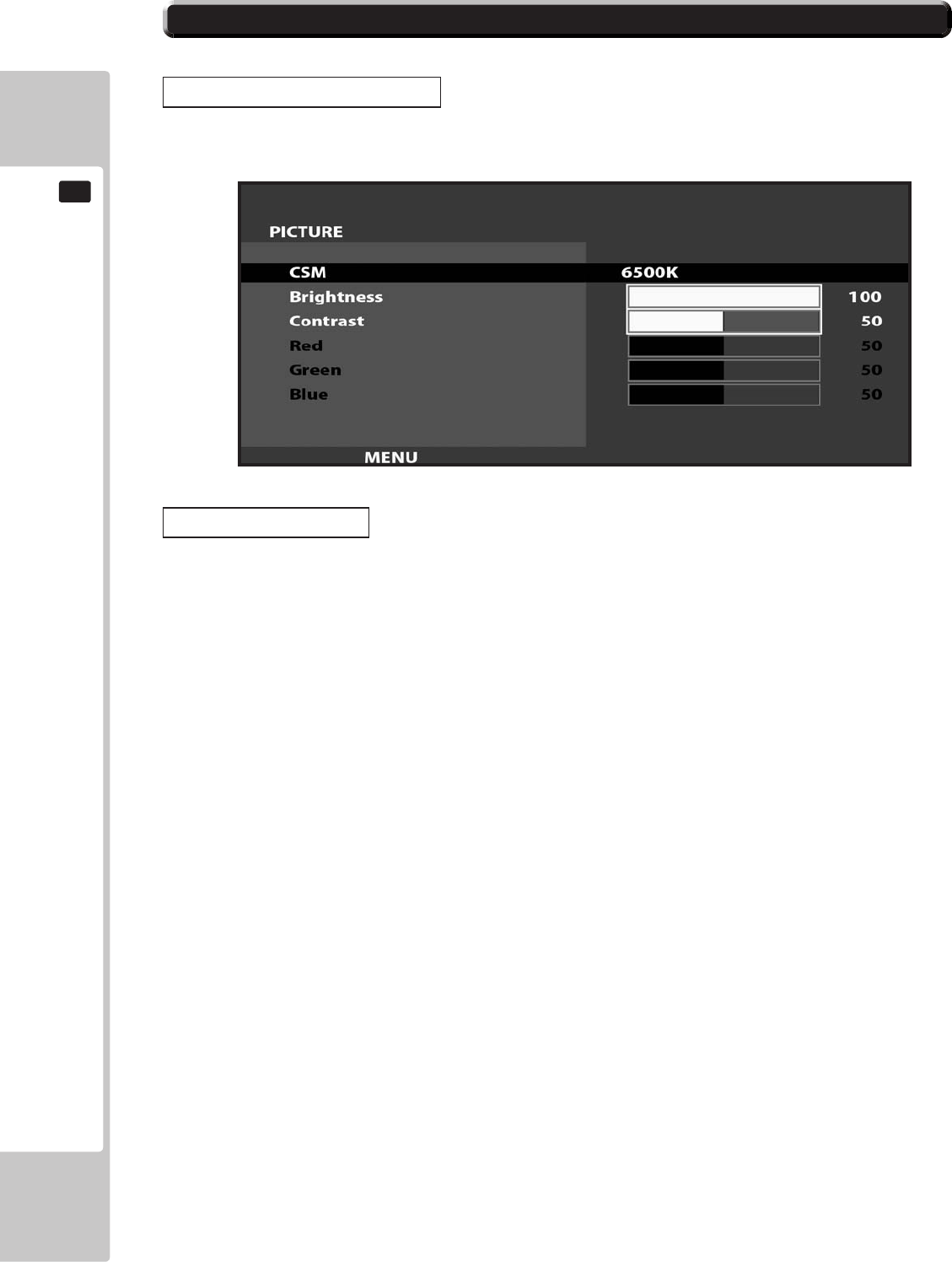
11-3 ADJUSTMENT METHOD
On-Screen Display (OSD)
Available Settings
11-3 Fig. 06
COIN HANDLING
87
12
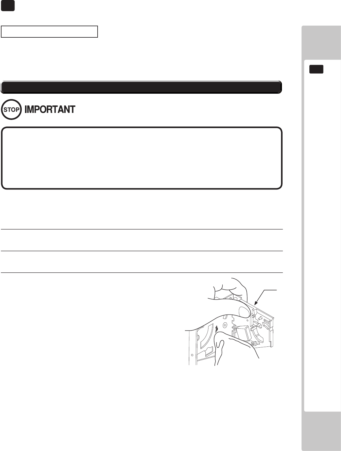
COIN HANDLING
12
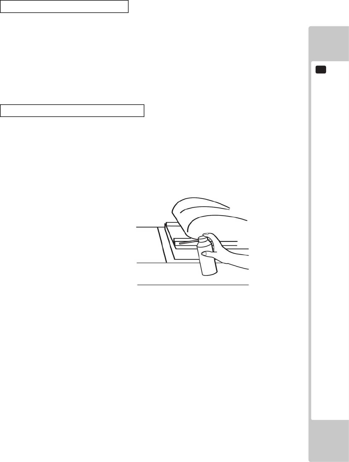
Handling the Coin Jam
TheCoinSelectorshouldbecleanedonceevery3months.
Whencleaning,followtheprocedurebelow:
1
2
3
FIG. 12 a
● Remove and clean smears by using a soft cloth dipped in water or diluted chemical
detergent and then squeezed dry.
● Never apply machine oil, etc. to the Coin Selector.
● After cleaning the Coin Selector, insert a regular coin in the normal working status
and ensure that the selector correctly functions.
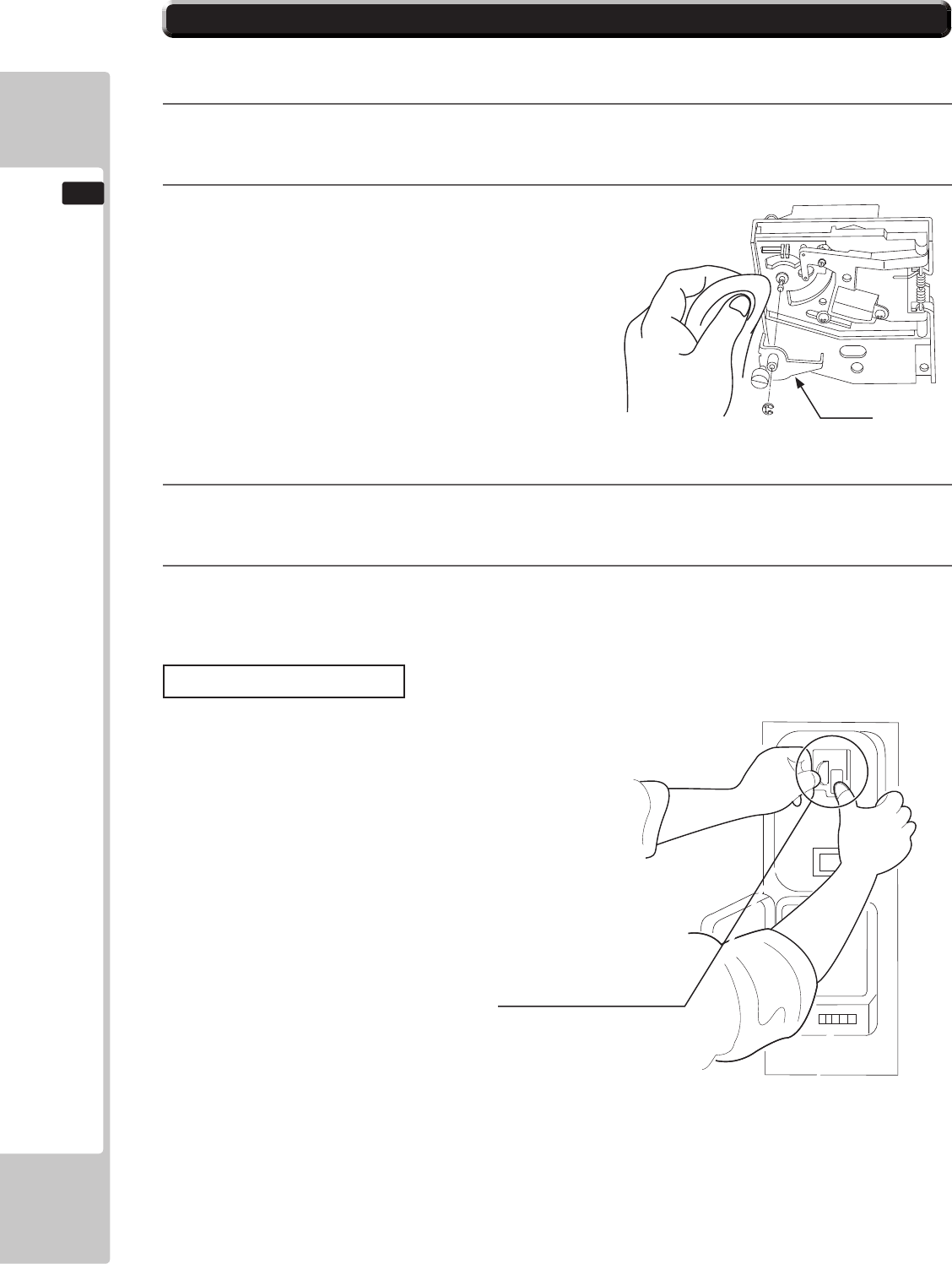
12-1 CLEANING THE COIN SELECTOR
GATE
88
COIN HANDLING
12
4
5
6
7
Coin Insertion Test
FIG. 12 c
12-1 CLEANING THE COIN SELECTOR
I
COIN HANDLING
89
12
.
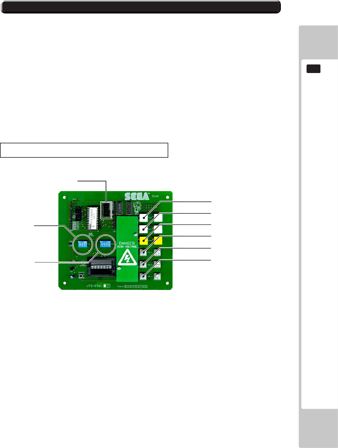
VTS Board
12-2 ADJUSTING THE PRICE OF PLAY
TEST BUTTON
SERVICE BUTTON
DEMAG (NOT USED)
VOLUME CONTROL A
VOLUME CONTROL B
VOLUME CONTROL C
DIP SW 3
DIP SW 1
COIN CHANNEL A
90
COIN HANDLING
12
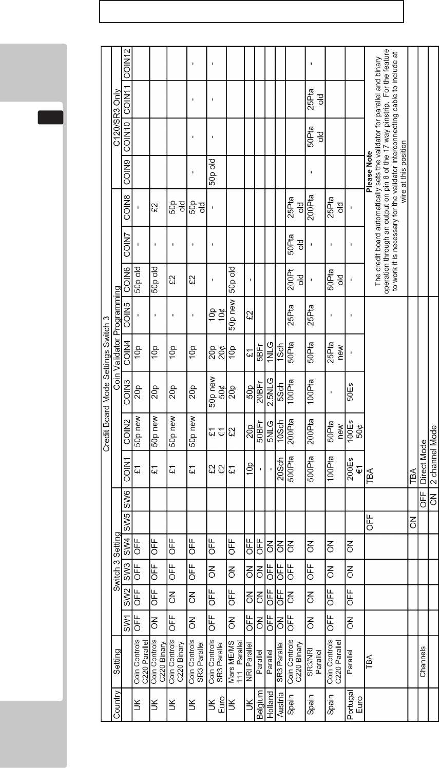
REGIONAL AND ACCEPTOR SETTINGS (SW3)
Note: These switch settings are under constant review and may change due to world currency updates.
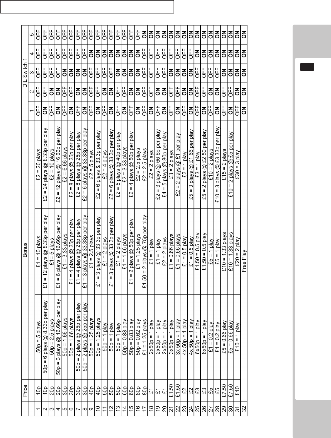
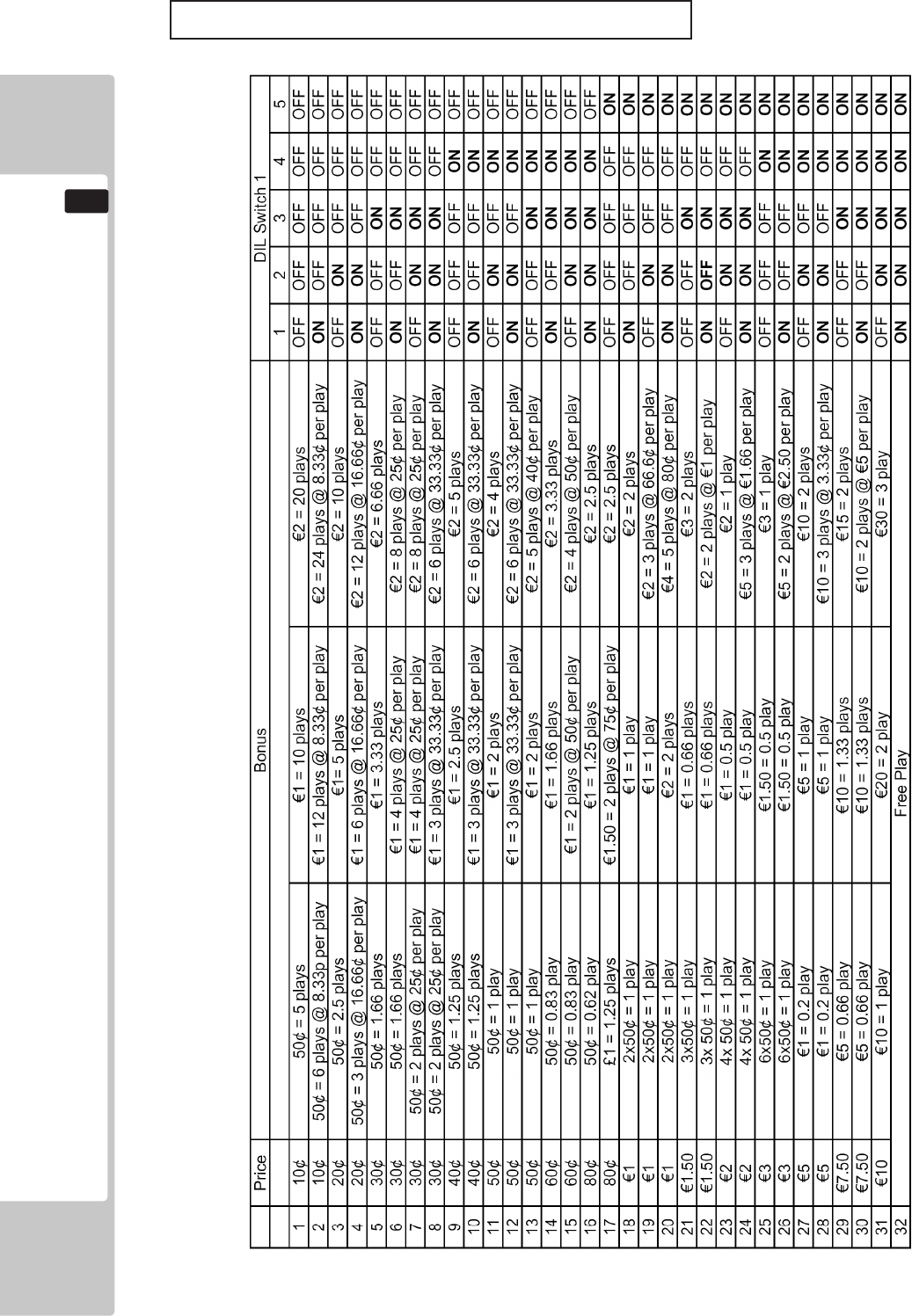
• Set SW 1 according to the option settings found in the relevant Price of Play Settings Table on the following pages.
• For Germany (DM), France (Fr) & Switzerland (SFr), use the appropriate existing setting shown above (from another country) that
matches the coin ratios programmed into your coin mech.
• Set SW 3 on the VTS /Excel board as shown in the table above corresponding to the country required.
COIN HANDLING
91
12
STERLING PRICE OF PLAY SETTINGS (SW1)
92
COIN HANDLING
12
EURO PRICE OF PLAY SETTINGS (SW1)
COIN HANDLING
93
12
BANK SELECT
SELECTING STERLING / EURO OPTION
TheSR3coinacceptor(supplied)isprogrammedtoacceptUKSterlingandtheEuro.Factorysettingis
fortheUKSterling.IfthecongurationneedstochangetotheEuro,thenpleasefollowtheinstructions
belowforchangingovertotheEuroandvisaversa.
12-3 SR3 OPTIONS - TEACH AND RUN PROGRAMMING
94
COIN HANDLING
12
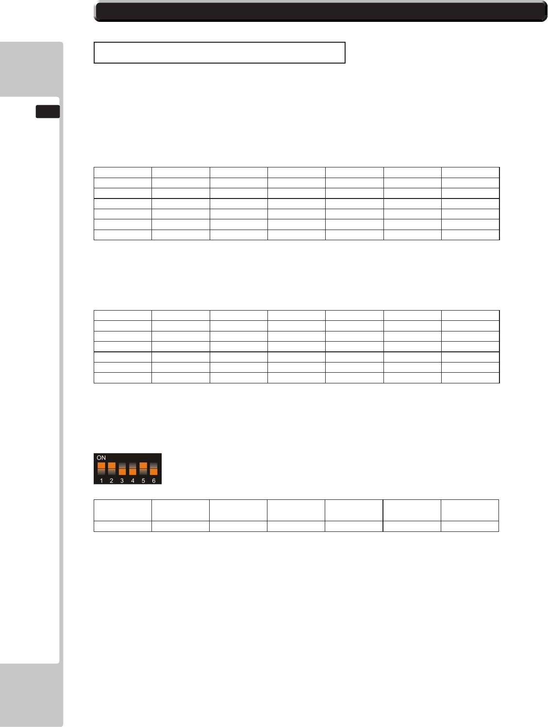
CoinNumber SW1 SW2 SW3 SW4 SW5 SW6
1 o o o ON ON o
2 o o ON o ON o
3 o o ON ON ON o
4 o ON o o ON o
5 o ON o ON ON o
6 o ON ON o ON o
CoinNumber SW1 SW2 SW3 SW4 SW5 SW6
7 o ON ON ON ON o
8 ON o o o ON o
9 ON o o ON ON o
10 ON o ON o ON o
11 ON o ON ON ON o
12 ON ON o o ON o
MSB
SW1 SW2 SW3 LSB
SW4 TOTAL SW5 SW6
ON ON OFF OFF 12 ON OFF
.
TEACH AND RUN PROGRAMMING (SR3)
If
12-3 SR3 OPTIONS - TEACH AND RUN PROGRAMMING
FLUORESCENT LIGHT/OTHER LAMPS REPLACEMENT
13
95
FLUORESCENT LIGHT/OTHER LAMPS REPLACEMENT
13
• Be careful when handling the plastic parts. Failure to observe this may cause injury
or damage due to fragments, etc.
• Do not attempt to replace billboard uorescent lamps while standing on the base. If
you should misstep while working, you could stumble or fall down.
• When working with the product, be sure to turn the power o. Working with the
power on may cause an electric shock or short circuit.
• You may get burned by a hot uorescent lamp or other lamps. Pay full attention to
the lamps when performing the work.
• Be sure to use lamps of the designated rating. Using lamps of undesignated rating
can cause a re or malfunctioning.
• There is the danger of short circuits or smoke generation due to deterioration of
insulation in lighting xtures resulting from age deterioration. Check for anomalies
such as the following: Does it smell like something is burning? Is there socket
discoloration? Are any lamps being replaced frequently? Do lamps not go on
properly?
13.1 FLUORESCENT TUBES - BILLBOARD
13.3 SIDE LIGHTS - LED CLUSTER - BILLBOARD
13.4 BUTTON LAMPS - CONTROL PANEL
13.2 RACE LEADER LAMPS - BILLBOARD

13
FLUORESCENT LIGHT/OTHER LAMPS REPLACEMENT
96
1
2
13.1 FLUORESCENT TUBES - BILLBOARD
THIS WORK ON TOP OF THE CABINET, SHOULD NOT BE UNDERTAKEN
WITHOUT THE USE OF A SUITABLE STEP OR FOOTSTOOL.
MAKE SURE THAT THE MAIN SUPPLY VOLTAGE TO THE MACHINE IS
SWITCHED OFF BEFORE ATTEMPTING TO CARRY OUT THIS WORK
6
ʻXʼ
ʻXʼ
ʻXʼ
ʻXʼ
NOTE : In order to extract all of the xings marked ‘X’ it may be necessary to remove part
of the POP display, if this is the case action one of the following options.
‘Player 1’ Cockpit - Go to CH6.3 ‘E’ and reverse engineer.
‘Player 2’ Cockpit - Go to CH6.3 ‘G’ and reverse engineer.
FLUORESCENT LIGHT/OTHER LAMPS REPLACEMENT
13
97
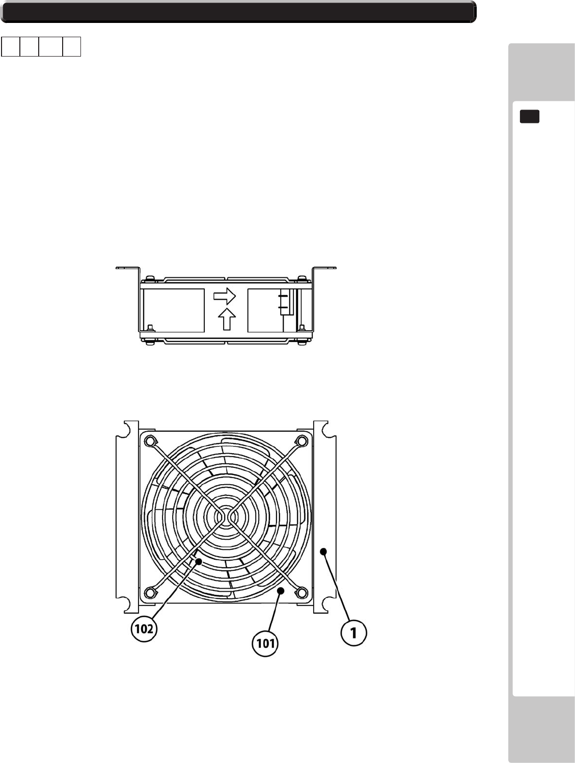
13.1 FLUORESCENT TUBES - BILLBOARD
A
102
101
3
6 SRS-1303UK COVER FL COMPARTMENT 1
101 390-0240-40UK FL TRAY 240V 40W 1
102 390-5695-40-DUK FL TUBE 40W 600L 1.5 1
A TERRY CLIP 2
4
.
13
FLUORESCENT LIGHT/OTHER LAMPS REPLACEMENT
98
13.2 RACE LEADER LAMPS - BILLBOARD
1
.
2
THIS WORK ON TOP OF THE CABINET, SHOULD NOT BE UNDERTAKEN
WITHOUT THE USE OF A SUITABLE STEP OR FOOTSTOOL.
MAKE SURE THAT THE MAIN SUPPLY VOLTAGE TO THE MACHINE IS
SWITCHED OFF BEFORE ATTEMPTING TO CARRY OUT THIS WORK
FLUORESCENT LIGHT/OTHER LAMPS REPLACEMENT
13
99
13.2 RACE LEADER LAMPS - BILLBOARD
1of6LampHolders
4
3
4 SRS-5050UK ASSY TRAY BULB R LEADER DX 1
5 SRS-1302UK COVER CCFL COMPARTMENT 1
12v **W WEDGE LAMP 6
4
13
FLUORESCENT LIGHT/OTHER LAMPS REPLACEMENT
100
13.3 SIDE LIGHTS - LED CLUSTER - BILLBOARD
THIS WORK ON TOP OF THE CABINET, SHOULD NOT BE UNDERTAKEN
WITHOUT THE USE OF A SUITABLE STEP OR FOOTSTOOL.
MAKE SURE THAT THE MAIN SUPPLY VOLTAGE TO THE MACHINE IS
SWITCHED OFF BEFORE ATTEMPTING TO CARRY OUT THIS WORK
1
.
2
FLUORESCENT LIGHT/OTHER LAMPS REPLACEMENT
13
101
13.3 SIDE LIGHTS - LED CLUSTER - BILLBOARD
103
2 SRS-1320UK ASSY LIGHT UNIT L 1
3 SRS-1330UK ASSY LIGHT UNIT R 1
103 838-0011UK LED HEADLAMP BD 2
3
4
13
FLUORESCENT LIGHT/OTHER LAMPS REPLACEMENT
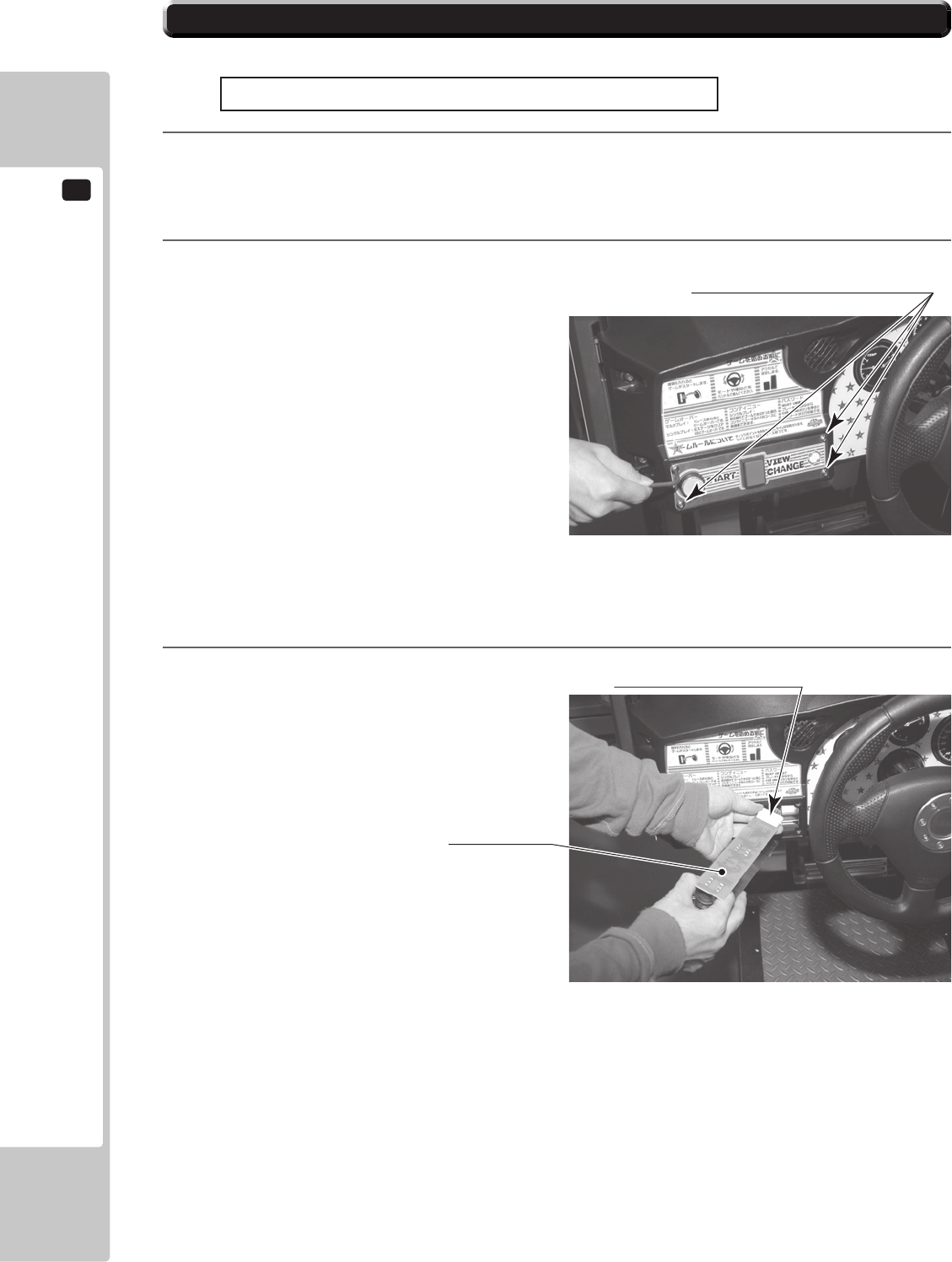
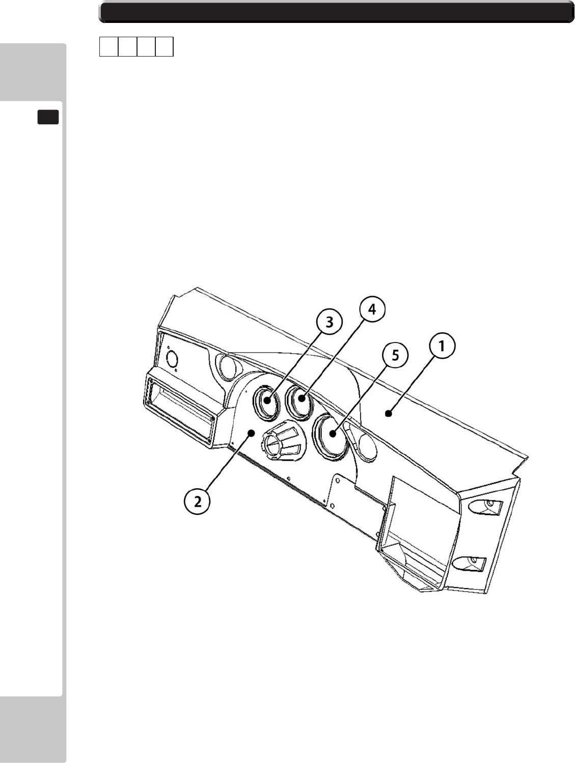
102
SWITCH PLATE
Disconnect the connector.
Start Button Lamp, View Change Button Lamp
1
2
TAMPERPROOF SCREW (4), chrome
M4x16
3
.
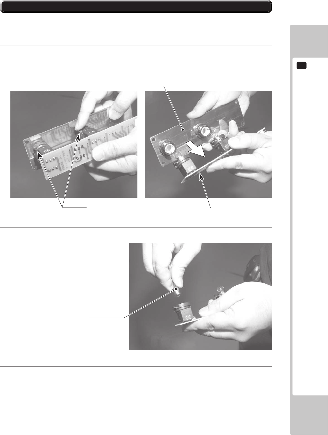
13.4 BUTTON LAMPS - CONTROL PANEL
FLUORESCENT LIGHT/OTHER LAMPS REPLACEMENT
13
103
4
5
Unlock. PRINTED CIRCUIT BOARD
BUTTON PLATE
LAMP 6.3V 1W
390-5445-01
6
13.4 BUTTON LAMPS - CONTROL PANEL
14
PERIODIC INSPECTION
104
PERIODIC INSPECTION
14
• Once a year, check to see if power cords are damaged, the plug is securely inserted,
dust is accumulated between the socket outlet and the power plug, etc. Using the
product with accumulated dust in the interior may cause re or electric shock.
• Never use a water jet, etc. to clean the inside and outside of the cabinet. If wetness
occurs for any reason, do not use the product until it has completely dried.
• Once a year, request the oce shown on this manual or the dealer from whom
the product was originally purchased to perform the internal cleaning. Using the
product with accumulated dust in the interior may cause re or other accidents.
Note that you are liable for the cost of cleaning the interior parts.
• There is the danger of accidents involving electrical shorts circuits or re caused by
factors such as the deterioration of insulation in electrical and electronic equipment
over time. Check that there are no abnormalities such as odors from burning.
14 TABLE 01 PERIODIC INSPECTION TABLE
PERIODIC INSPECTION
14
105
Cleaning the Cabinet Surfaces
Seat (Greasing to Seat Rail Portion)
14-0 FIG. 01
15
TROUBLESHOOTING
106
TROUBLESHOOTING
15
15-1
TROUBLESHOOTING (WHEN NO ERROR MESSAGE IS SHOWN)
• In order to prevent electric shock and short circuit, be sure to turn power o before
performing work.
• Be careful so as not to damage wirings. Damaged wiring can cause electric shock or
short circuit.
• After removing the cause of the functioning of the Circuit Protector, reinstate the
Circuit Protector. Depending on the cause of the functioning, using the Circuit
Protector as is without removing the cause can cause generation of heat and re
hazard.
• In the event that a problem cannot be resolved by employing the procedures listed
in this Manual, be sure to request service from the oce shown on this Manual or
the dealer from whom the product was originally purchased. Attempts to employ
procedures other than those specied in this Manual can cause electrical shock,
shorting, or re.
• In the event of a problem that is not described here, be sure to contact the oce
shown on this Manual or the dealer from whom the product was originally
purchased. Careless attempts at repair can result in electrical shock, shorting, or re.
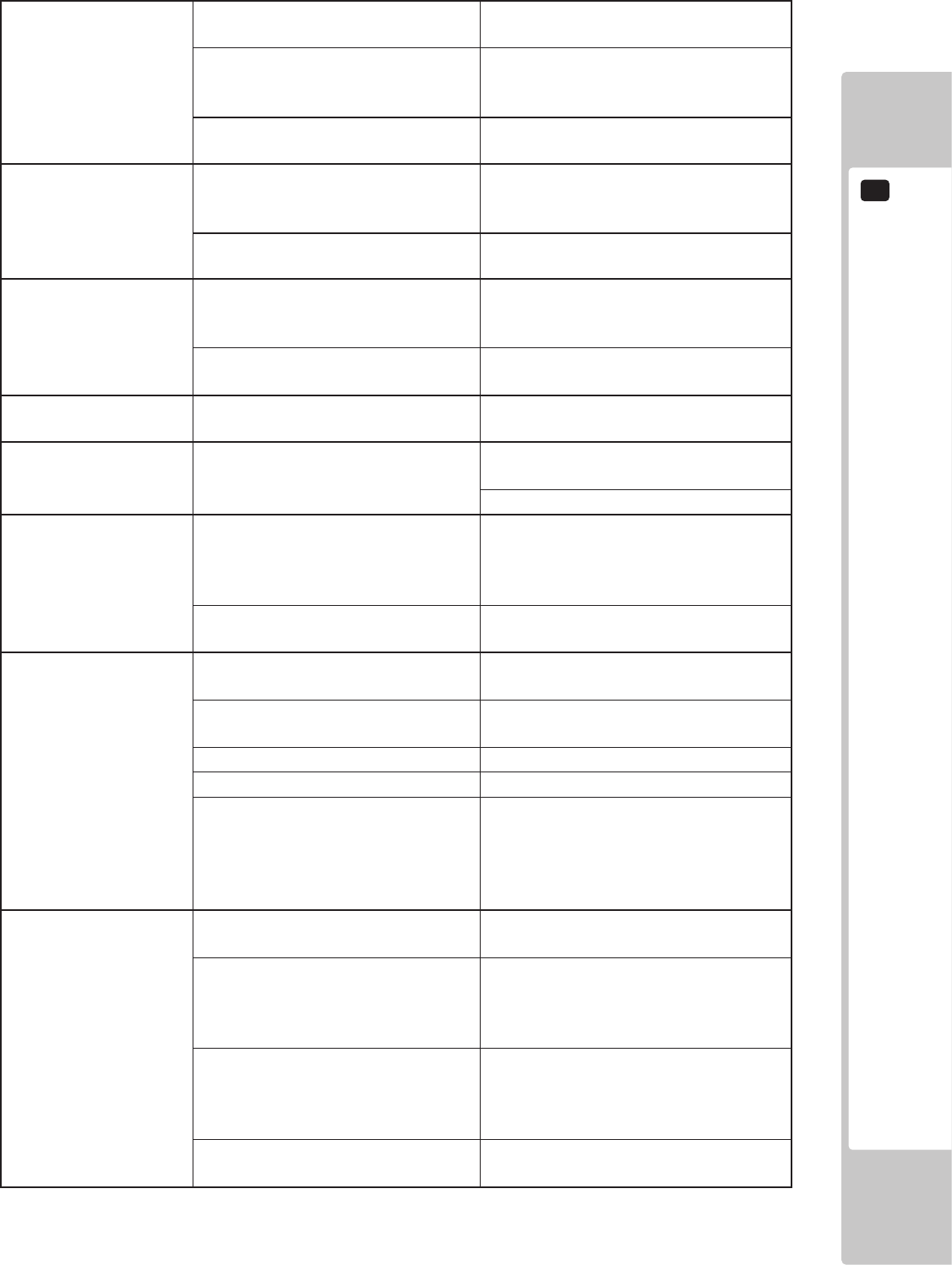
15 TABLE 01
TROUBLESHOOTING
15
107
15
TROUBLESHOOTING
108
TROUBLESHOOTING
15
109
• In case fuse replacements other than those stated in this manual are necessary,
contact where you purchased the product from for inquiries regarding this matter.
• In order to prevent an electric shock, be sure to turn power o and unplug from the
socket outlet before performing work by touching the internal parts of the product.
• Be careful so as not to damage wirings. Damaged wiring can cause electric shock
and short circuit accidents.
• Be sure to use fuses meeting specied rating. Using fuses exceeding the specied
rating can cause re and electric shock accidents.
• After eliminating the cause of the blowing of fuse, replace the fuse. Depending
on the cause of fuse blowing, continued use with the fuse as is blown can cause
generation of heat and re hazard.
Replacing Fuses
GAME BOARD
16
● Whenworkingwiththeproduct,besuretoturnthepoweroff.Workingwiththe
poweronmaycauseanelectricshockorshortcircuit.
● Becarefulnottodamagethewires.Damagedwiresmaycauseanelectric
shock,shortcircuitorpresentariskofre.
● Donotusethisproductwithconnectorsotherthanthosethatwereconnected
andusedwiththegameboardatthetimeofshipping.Donotcarelesslycon-
nectwirestoconnectorsthatwerenotusedatthetimeofshipping,asthismay
causeoverheating,smokeorredamage.
Inthisproduct,settingchangesaremadeduringthetestmode.Thegame
boardneednotbeoperated.Usethegameboard,etc.asiswiththesameset-
tingmadeatthetimeofshipmentsoasnottocauseelectricshockandmal-
functioning.
StaticelectricityfromyourbodymaydamagesomeelectronicsdevicesontheIC
board.BeforehandlingtheICboard,touchagroundedmetallicsurfacesothat
thestaticelectricitycanbedischarged.
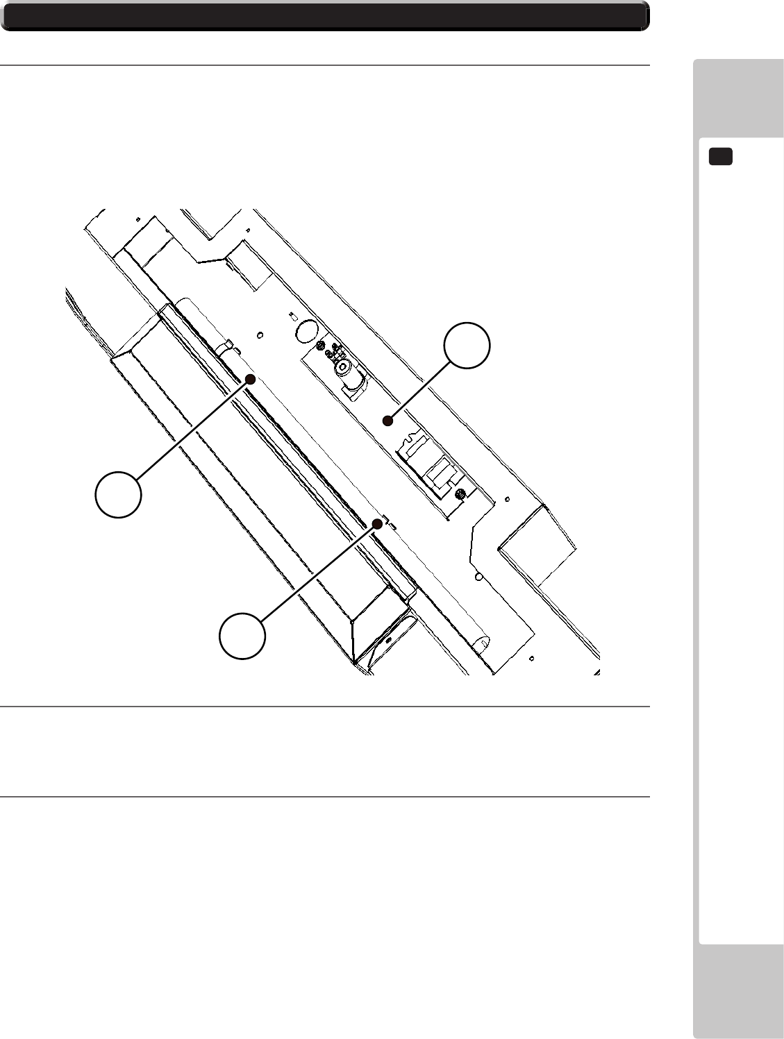
16-1 CONTROL BOARDS - LOCATION
1
●Whenreturningthegameboardaftermakingrepairsorreplacements,make
surethattherearenoerrorsintheconnectionofconnectors.Erroneouscon-
nectionscanleadtoelectricalshock,shortcircuitsorres.
●Whenconnectingaconnector,checkthedirectioncarefully.Connectorsmust
beconnectedinonlyonedirection.Ifindiscriminateloadsareappliedinmak-
ingconnections,theconnectororitsterminalxturescouldbedamaged,re-
sultinginelectricalshock,shortcircuitsorres.
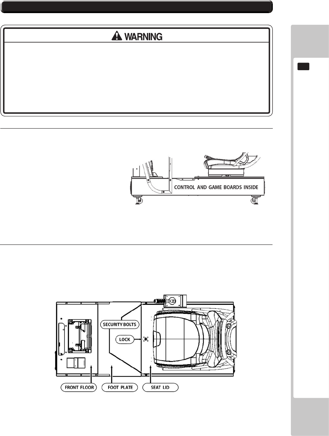
16-1 CONTROL BOARDS - LOCATION
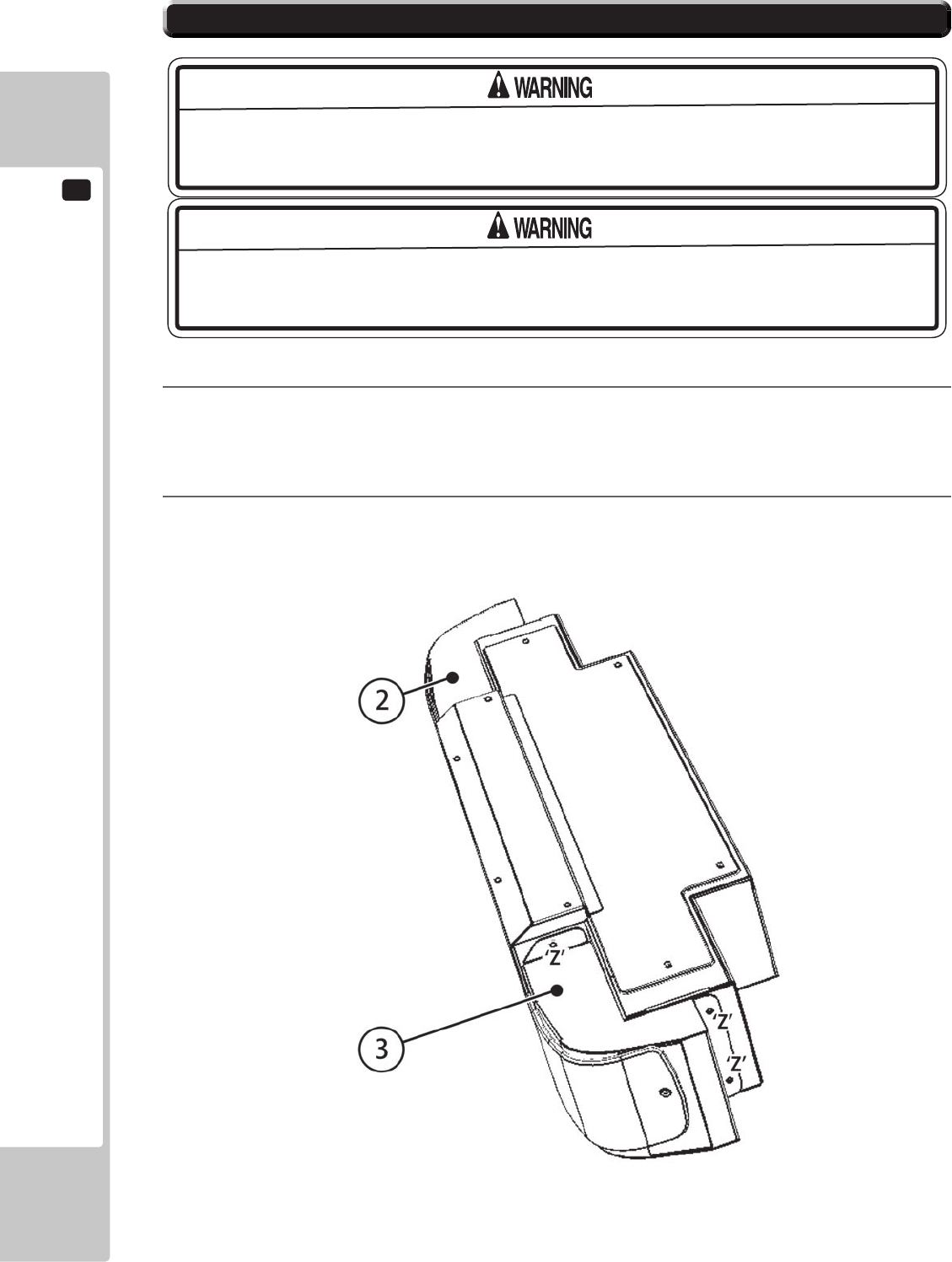
2
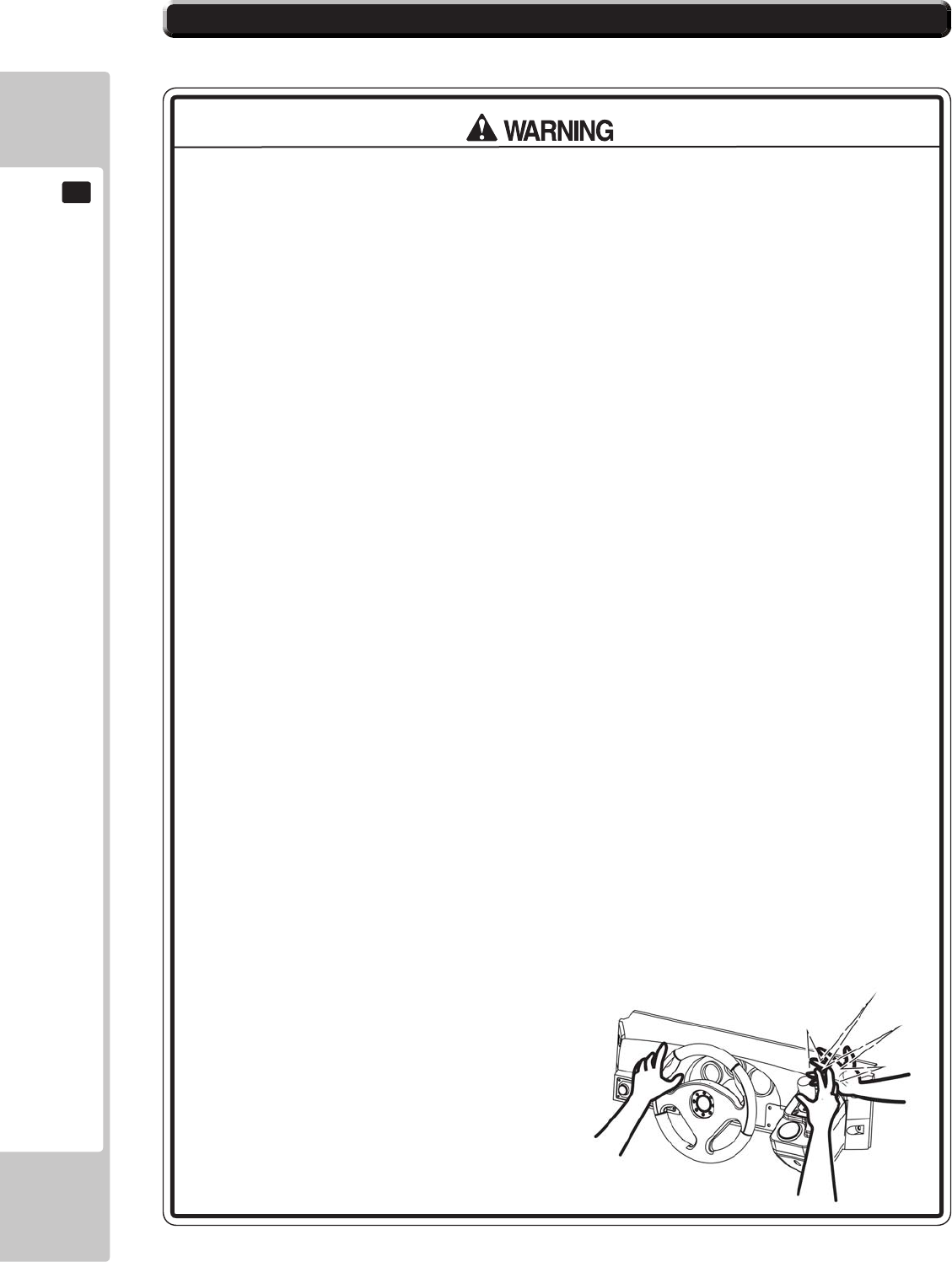
GREAT CARE SHOULD BE TAKEN WHEN OPENING AND CLOSING THIS UNIT.
LIKELY CHANCE OF MACHINE DAMAGE OR PERSONNEL INJURY IF UNIT IS DROPPED
DURING OPENING, WITH A CHANCE OF FOREIGN BODIES GETTING TRAPPED WHEN
CLOSING THE UNIT, CAUSING PERSONNEL INJURY.
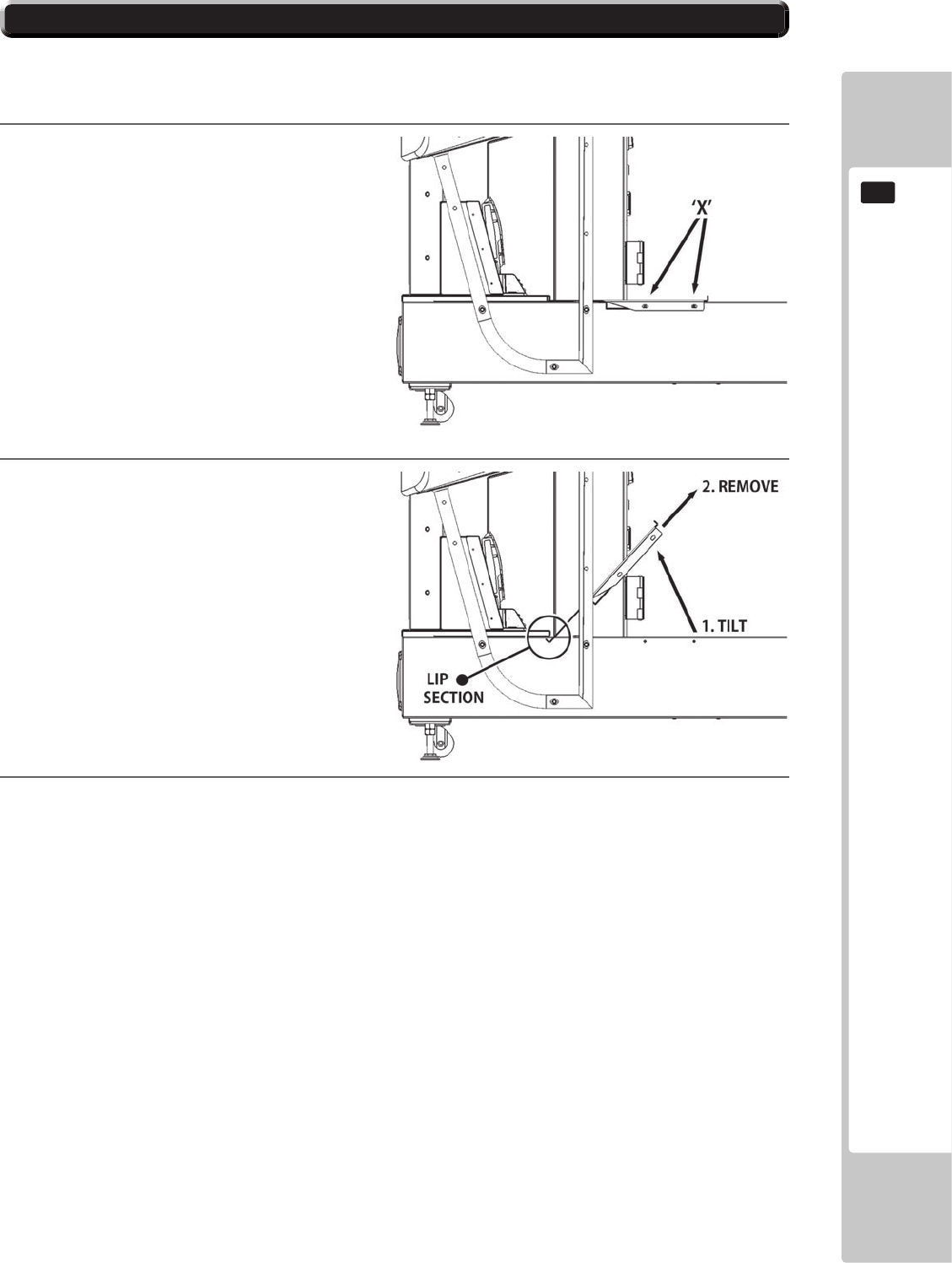
3
4
5
16-1 CONTROL BOARDS - LOCATION
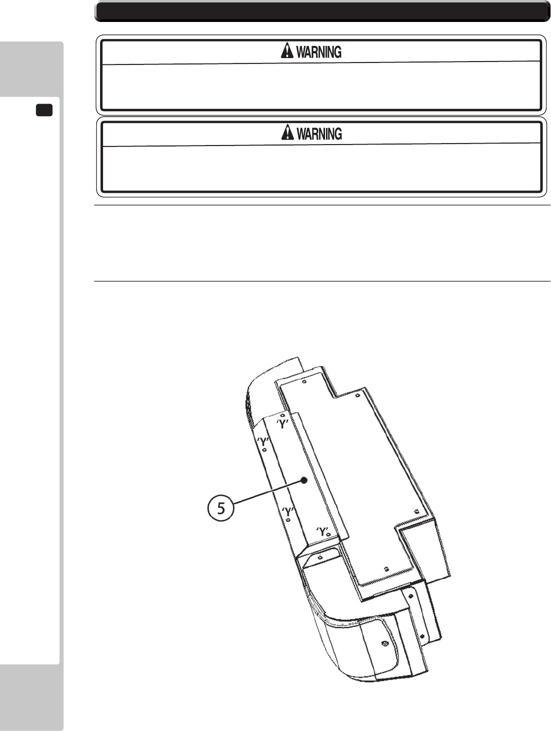
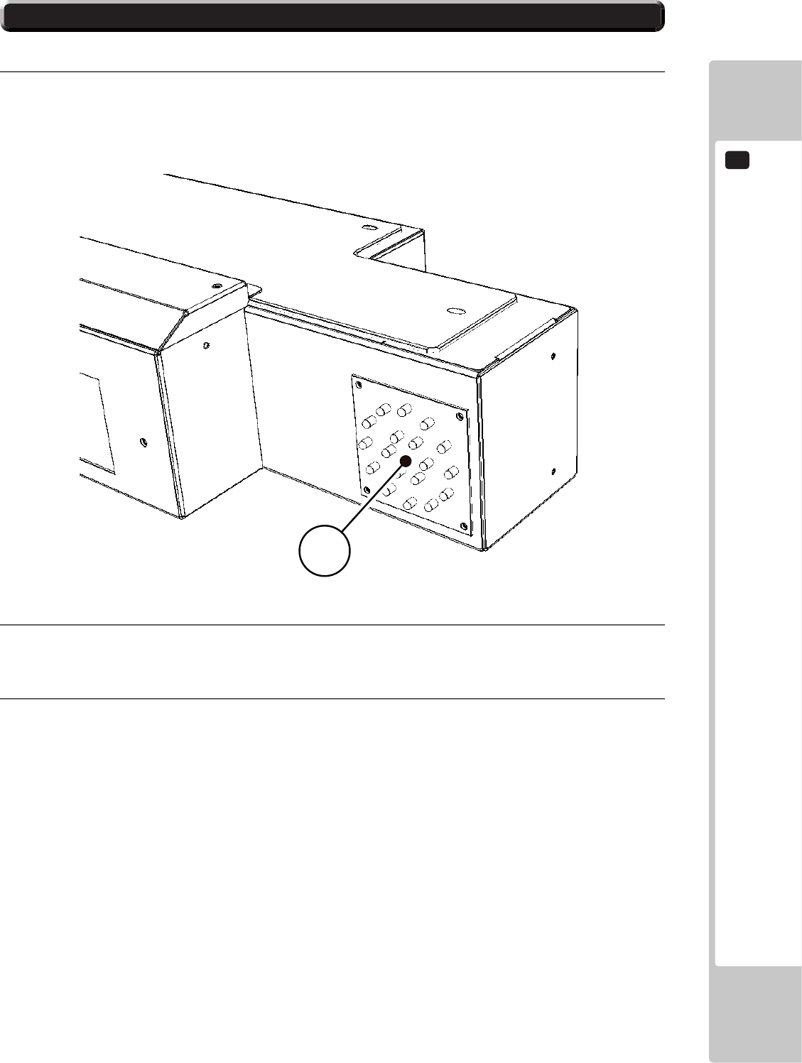
16-2 CONTROL BOARDS - IDENTIFICATION
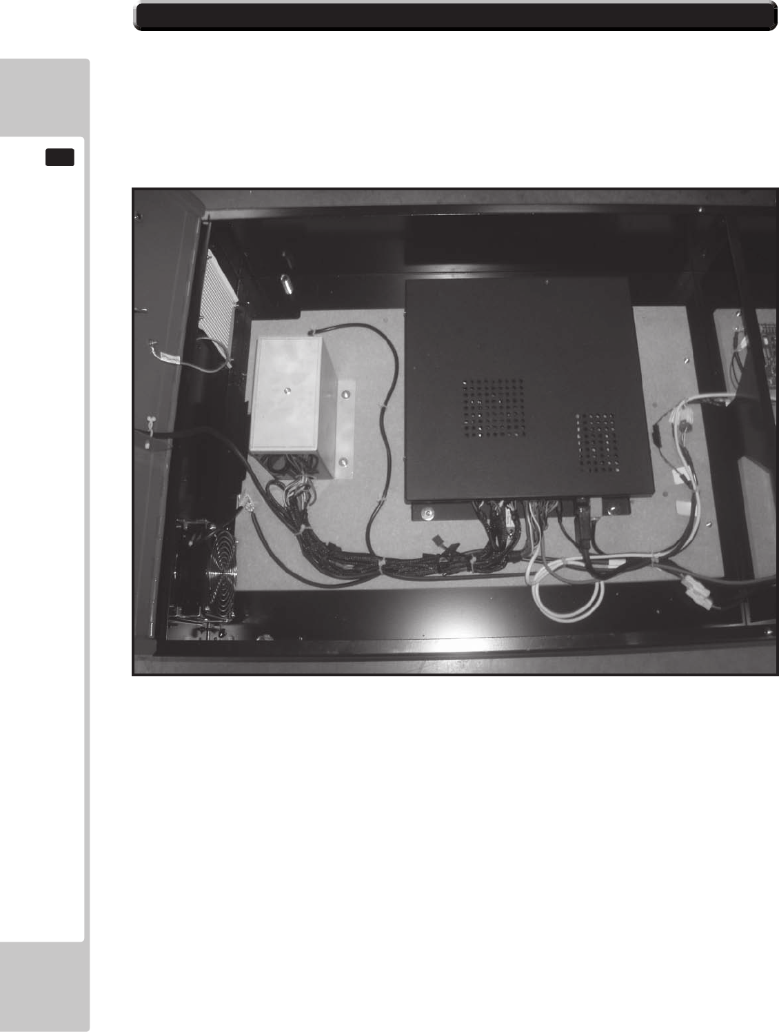
EUROPA
GAMEBOX
GAMEBOX
POWER
SUPPLY
VIEW OF THE GAME UNIT AND POWER SUPPLY
LOCATED UNDERNEATH THE PLAYER SEAT
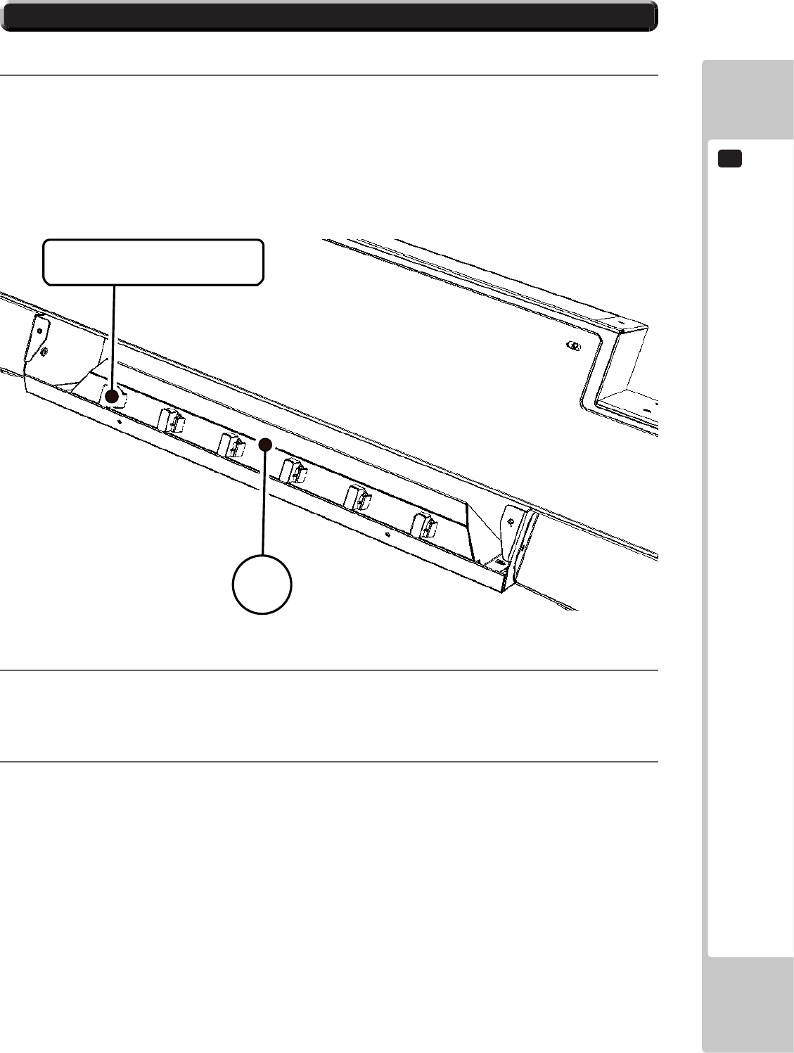
16-2 CONTROL BOARDS - IDENTIFICATION
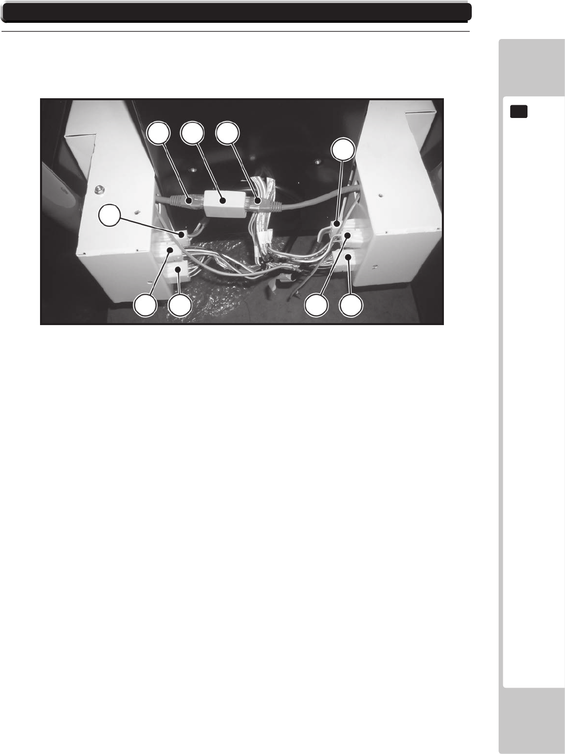
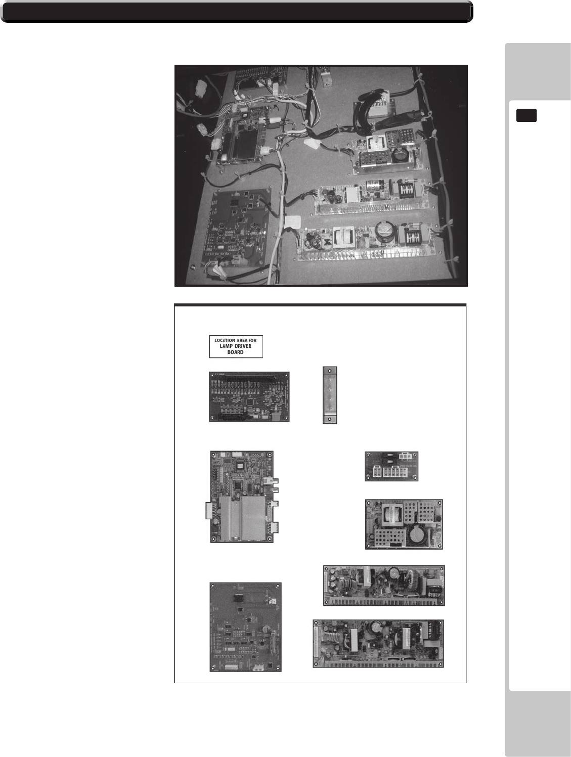
INPUT-OUTPUTBOARD
COMMON
EARTHPOINT
240VAC
DISTRUBUTIONBOARD
SOUNDBOARD
STEERINGWHEEL
INTERFACEBOARD
PSU-STEERINGINTERFACEBOARD
PSU-SOUNDBOARD
PSU-I/OBOARD
VIEW OF THE
ELECTRICAL BOARD
ASSEMBLY LOCATED
UNDERNEATH THE
FRONT FLOOR
SECTION OF THE BASE
DETAILS ON THE
FUNCTION OF EACH OF
THE CONTROL BOARDS
.
17
COMMUNICATION PLAY
116
COMMUNICATION PLAY
17
17-1 INSTALLATION PRECAUTIONS
• To perform work safely, be sure to secure the space corresponding to number of
machines to be linked. Failure to observe this can cause accident.
• To avoid accidents, use a cable cover that will not cause patrons to trip when laying
network cables in areas of heavy foot trac.
• To prevent accidents and acts of vandalism, cover the network cables with the
strongest cover possible.
• Before starting to work, ensure that the Power SW is OFF. Failure to observe this can
cause electric shock or short circuit.
• Use care so as not to damage wirings. Damaged wiring can cause electric shock or
short circuit.
• Do not touch undesignated places. Touching places not designated can cause
electric shock or short circuit.
• The work described below should be carried out by the site maintenance personnel
or other qualied professional. Work carried out by personnel without the necessary
skill or technology can cause accident.
• To perform work safely and avoid serious accident such as the cabinet falling down,
do not perform work in places where step-like grade dierences, a ditch, or slope
exist.
• To prevent accidents while working or while operating the product after it has been
installed, be sure not to conduct any procedures other than those given in this
manual. There are cases in which procedures not covered in this manual require
special tools and skills. If a procedure not given in this manual is required, request
service from the oce given in this manual or from the point of purchase.
For this game, up to 6 machines can be networked together allowing up to 6 players to play
simultaneously. In this instance, connecting the communication cable and adjustment to the
settings for communication play will be required
COMMUNICATION PLAY
17
117
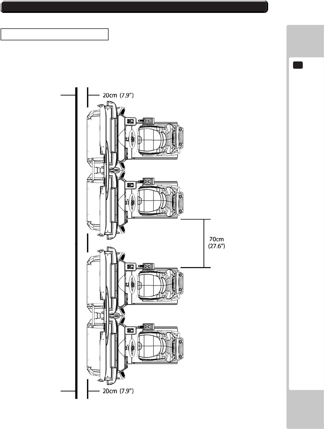
Distance between Machines
The maximum distance between the game machines depends on the length of the cables connecting
them, but make sure the units are separated from each other by at least 70 cm (27.6 in) so that players
can pass between them.
17-1 INSTALLATION PRECAUTIONS
17
COMMUNICATION PLAY
118
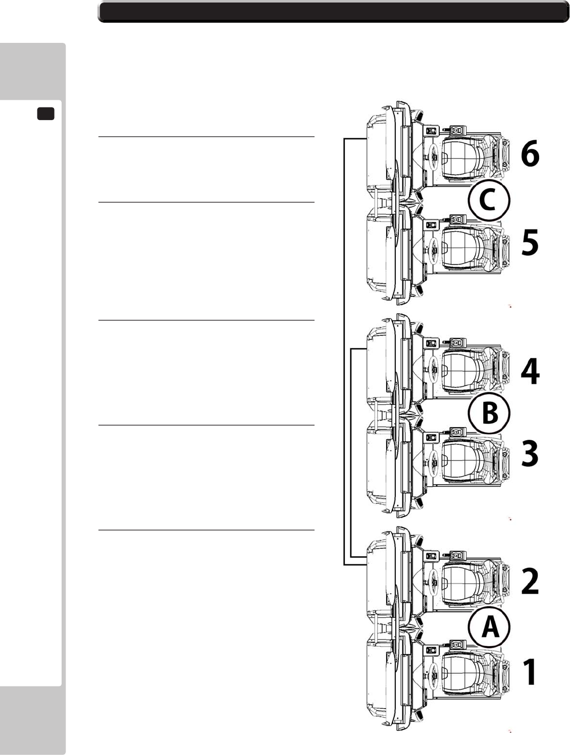
To enable network play, the Hubs inside each of the game machines involved must be connected with
network (LAN) cables. Up to a maximum of 3 machines (6 Players) can be Networked together, all
thats required is to link between the Hubs of each of the machines that are to complete the ‘Network’.
Do not connect LAN cables to game machines when they are not used for network play.
17-2 CONNECTING THE COMMUNICATION CABLE
1
Turnothepowerandunplugthe
powercordfromtheoutlet.
2
UsingChapter6ofthismanualas
reference,movethemachinessothat
theyarelinedup.
LeaveenoughspacebehindeachUnit
toallowaccesstotheNetworkHUB
whichislocatedintheSlaveCockpitof
eachMachine.
3
WiththisNetworkSystem,thetwo
Cockpitsineachmachinearealready
conguredandconnectedintothe
network,leavingonlythemachinesto
betobeconnectedtocompletethe
networksystem.
4
5
COMMUNICATION PLAY
17
119
17-2 CONNECTING THE COMMUNICATION CABLE
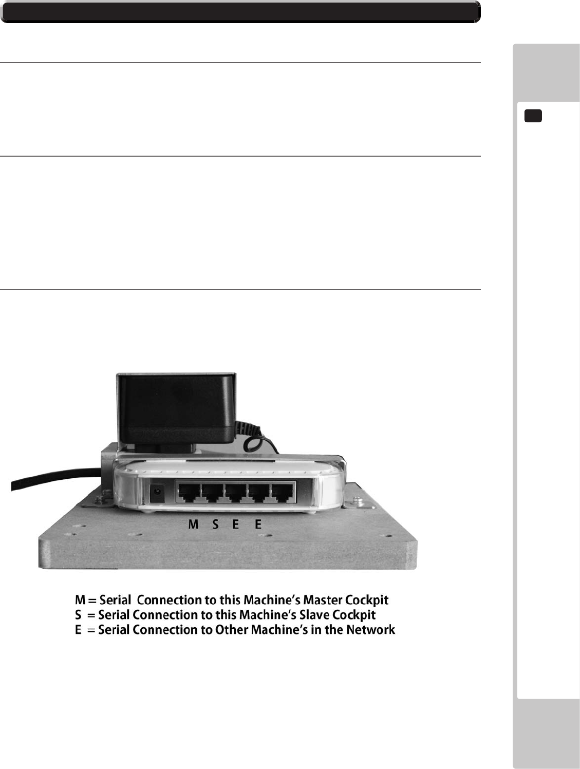
5
MachineB-willonlyusethreeofthePorts
MachineC-willonlyusethreeofthePorts.
6
NOTE : The ‘E1’ and ‘E2’ Ports are brought out to external LAN Connectors located at the back
of the ‘Player 2’ Cockpit base.

17
COMMUNICATION PLAY
120
17-3 NETWORK PLAY SETTINGS
Eachofthelinkedmachinesmustbesetupfornetworkplay.Ifthemachinesarenotsetupcorrectly,
networkplaywillnotbepossible.
Forthisgame,upto4machinescanbeconnectedtoallowupto4playerstoplaysimultaneously.
1
Turnonthepoweroneachmachinetobeusedinnetworkplay.
2
CauseallofthemachinestoentertheTestMode.
3
SelecttheGAMETESTMODEandpresstheTestbuttontodisplaytheGAMETESTMENUscreen.
4
SelecttheNETWORKSETTINGSintheGAMETESTMENUscreenandpresstheTestbutton.
5
PerformtheCABINETIDsetting.SetthedierentIDnumbertoeachmachine.Besuretoassign
oneofthemwiththeIDnumberof“1”
6
CauseallofthemachinestoexitfromtheTESTMODE.AlwaysselectEXITintheSYSTEMTEST
MENUscreen.
PLAYER 1
NETWORK SETTINGS
SELECT WITH SERVICE BUTTON
AND PRESS TEST BUTTON
NETWORK STATUS ON
CABINET CONNECTED 0
NETWORK ENABLED YES
CABINET ID 1
CONFIRM CHANGES
EXIT
>>
COMMUNICATION PLAY
17
121
• In network play, diculty level and other settings are made from CABINET ID Number
1. Changing the settings at CABINET ID Number 1 also changes the settings for other
units.
• If one of the units attached for network play enters Test Mode, the other unit will
display the Error screen.
• Even when units are connected for network play, each seat, each game may be
given dierent cost settings. Incorrect cost settings may cause budget balancing
problems.
17-4 NETWORK PLAY PRECAUTIONS
.

17
COMMUNICATION PLAY
122
NOTES ON NETWORKING
No. Number Description Quantity Assembly
1 SRS-0013UK POP CENTRE SRS TW 1 SRS-INST-TW / 21
2 SRS-0014UK POP L SRS TW 1 SRS-INST-TW / 22
3 SRS-0015UK POP R SRS TW 1 SRS-INST-TW / 23
4 SRS-0030UK STICKER INFILL 1 SRS-INST-TW / 29
5 SRS-0031UK STICKER CONTROL PANEL 2 SRS-2000UK / 14
6 SRS-0032UK STICKER SEAT NUMBERS 1 SRS-INST-TW / 30
9 SRS-1501UK STICKER BASE 4 SRS-10001UK / 20
11 SRS-1503UK STICKER BASE LID REAR 2 SRS-10001UK / 22
12 SRS-1504UK STICKER BASE REAR 2 SRS-10001UK / 23
13 SRS-1602BUK STICKER HEADREST REAR 2 SRS-1600UK / 22
14 SRS-1603UK STICKER SEAT BACK 2 SRS-1600UK / 23
15 SRS-0252UK RACE LEADER 2 SRS-1300UK / 22
16 SRS-1152UK STICKER SIDE POD 2 SRS-1050UK / 2
16 SRS-1152UK STICKER SIDE POD 2 SRS-1060UK / 2
17 SRS-1153UK STICKER SIDE POD PIRELLI 2 SRS-1050UK / 3
17 SRS-1153UK STICKER SIDE POD PIRELLI 2 SRS-1060UK / 3
For the warning display stickers, refer to Section 1.
DESIGN-RELATED PARTS
18
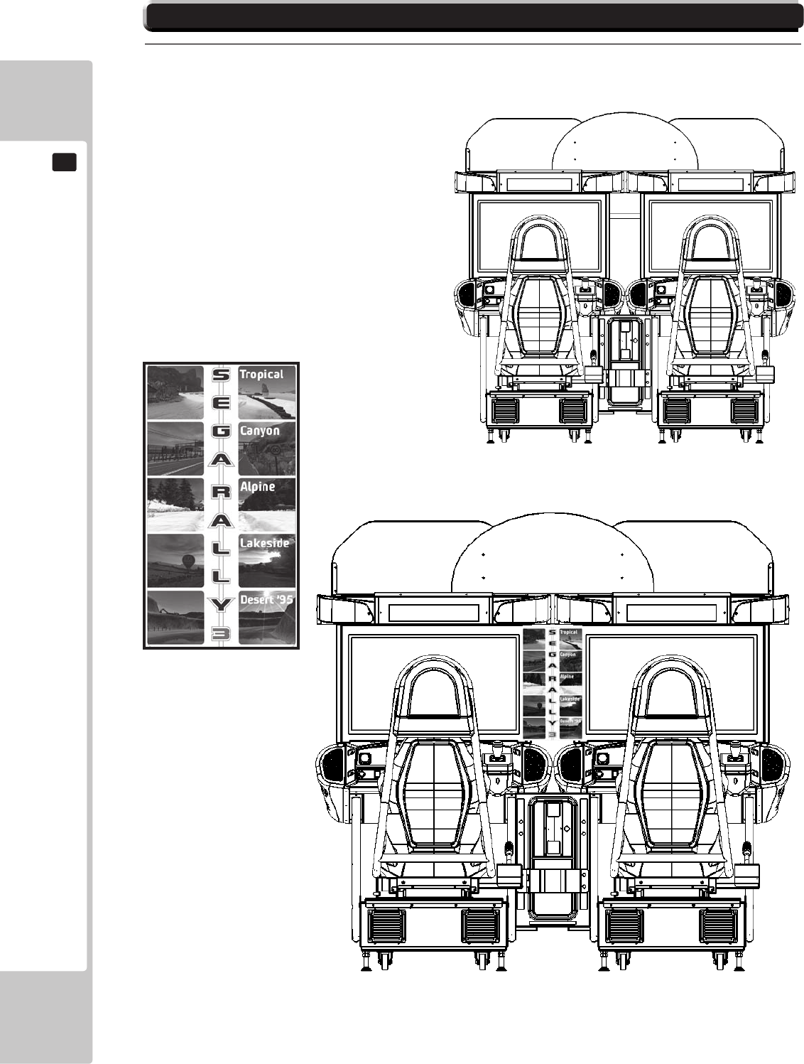
15 1
2
3
4
13
14 11
12
9
5
16
17
18-1 DESIGN RELATED PARTS
PARTS LIST
125
19
PARTS LIST
19 BRAKEDOWN ON ALL SUB ASSEMBLIES
1SRS-0001UK 1SRS-10001UK 1SRS-1120UK 2SRS-1130UK
TOPASSYSEGARALLY3Twin ASSY-COCKPIT1P
X2
ASSY-SUBMAINBASE ASSY-240VFAN
2SRS-4800UK 2SRS-1550UK
ASSY-HUB ASSY-SPEAKERL
4SRS-0400UK 3SRS-1560UK
ASSY-ACBRKTMAIN ASSY-SPEAKERR
5SRS-0700UK 4SRS-2000UK 4SRS-2001UK
ASSY-ACBRKTSUB ASSY-CONTROLPANELTWIN ASSY-CONTROLPANELCOVER
6SRS-1200UK 12 SRS-2100UK
ASSY-PEDALBASESRS ASSY-SWPLATE
7SRS-1150UK
ASSY-SIDEPODL
8SRS-1160UK
ASSY-SIDEPODR
11 SRS-1300UK 2SRS1320UK
ASSY-BILLBOARD ASSY-LIGHTUNITL
13 SRS-1600UK 3SRS1330UK
ASSY-SEATTWIN1P ASSY-LIGHTUNITR
14 SRS-4500UK 4SRS5050UK
ASSY-MAINBOARD ASSY-TRAYBULBRACELEADER
15 SRS-4600UK
ASSY-ELECBD
16 SRS-4700UK
ASSY-PSULCDBD
17 SRS-1510UK
ASSY-BASELIDR
3SRS-INST-TW 2SRS-0300UK
INSTALLATIONKITSRSTWIN ASSY-COINCHUTETOWER
SEGARALLY3TWIN-ASSYSTRUCTURE

126
PARTS LIST
19
19 PARTS LIST SRS-0001UK 1/2
TOP ASSEMBLY (SRS-0001UK)
1
No. Component Part Description Quantity
ABCD
PARTS LIST
127
19
19 PARTS LIST SRS-0001UK 2/2
TOP ASSEMBLY (SRS-0001UK)
1
ABCD
21 21
22 22
23 23
57 6 4
COCKPIT
MASTER
COCKPIT
SLAVE
11

128
PARTS LIST
19
19-1 PARTS LIST SRS-10001UK 1/4
ASSY - COCKPIT 1P (SRS-10001UK)
1 1
No. Component Part Description Quantity
----- --------------------------------------------------- ---------------
1 SRS-1120UK ASSY SUB MAIN BASE 1
2 SRS-1550UK ASSY SPEAKER L 1 *
3 SRS-1560UK ASSY SPEAKER R 1 *
4 SRS-2000UK ASSY CONTROL PANEL TWIN 1
5 SRS-1021UK COCKPIT BASE 1 *
6 SRS-1200UK ASSY PEDAL BASE SRS 1
7 SRS-1150UK ASSY SIDE POD L 1
8 SRS-1160UK ASSY SIDE POD R 1
9 SRS-1023XUK MONITOR STAND L 1
10 SRS-1024XUK MONITOR STAND R 1
11 SRS-1300UK ASSY BILLBOARD 1
13 SRS-1600UK ASSY SEAT TWIN 1P 1
14 SRS-4500UK ASSY MAIN BD 1 *
15 SRS-4600UK ASSY ELEC BD 1 *
16 SRS-4700UK ASSY ELEC BD LCD 1 *
17 SRS-1510UK ASSY BASE LID R 1
18 RAL-2007X RUBBER HOLDER R TWIN 1 *
19 RAL-2008X RUBBER HOLDER L TWIN 1 *
20 SRS-1501UK STICKER BASE L 1 *
22 SRS-1503UK STICKER BASE LID 1 *
23 SRS-1504UK STICKER BASE REAR 1 *
24 SRS-2031UK FRONT FLOOR SRS 1
26 SRT-2031UK NEOPRENE RUBBER STRIP 10X3mm 0.9 *
27 OS1004 DRAFT EXCLDR 4 X7MM BLK x 10M 0.8 *
28 SRS-0027UK PLATE BLANK CCT HOLE 1 *
30 440-WS0220UK WARNING STICKER TRAP HAZARD 1 *
31 SRS-1025UK COCKPIT SIDE L 1 *
32 SRS-1026UK COCKPIT SIDE R 1 *
33 SRS-1027UK BRKT CLOSING CTRL PNL BTM 1 *
34 SRS-1028UK FRAME REAR 2
40 SRS-1401UK BASE LCD MTG 1 *
41 SRS-1402UK BRKT RETAINER PILLAR 2 *
42 SRS-1403UK PILLAR LCD L 1
43 SRS-1404UK PILLAR LCD R 1
44 SRS-1405UK BRKT CLOSING CTRL PNL LCD TOP 1 *
45 123-5123 STUD BOLT M6 FOR LCD 6 *
101 200-6032-SMSNG ASSY LCD 32 SMSNG LTA320WT-L16 1
105 253-5569 BUSH FOR LCD 6 *
106 280-5113 COLLAR FOR TV 6 *
110 601-6231-D100 EDGING NEW TYPE 2 *
115 280-A00964-WX ROUTER TWIST D09 SO6.4 WOOD X 4 *
116 280-A01264-WX ROUTER TWIST D12 SO6.4 WOOD X 7 *
117 280-A02064-WX ROUTER TWIST D20 SO6.4 WOOD X 3 *
201 000-P00412-W M4X12 MSCR PAN W/FS PAS 12 *
202 FAS-290040 HEX SKT SCR BH BLK M8X25 4 *
203 060-S00800-0B M8 WSHR SPR BLK 4 *
ABCD

PARTS LIST
129
19
19-1 PARTS LIST SRS-10001UK 2/4
ASSY - COCKPIT 1P (SRS-10001UK)
1 1
ABCD
No. Component Part Description Quantity
----- --------------------------------------------------- ---------------
204 060-F00800-0B M8 WSHR FORM A FLT BLK 4 *
205 020-000830-0Z M8X30 SKT CAP OZ 6 *
206 030-000625-SB M6X25 BLT W/S BLK 2 *
207 031-000625-0B M6X25 CRG BLT BLK 2 *
208 050-F00600 M6 NUT FLG SER PAS 12 *
209 068-651616-0B M6 WSHR 16OD FLT BLK 16 *
210 068-651616 M6 WSHR 16OD FLT PAS 8 *
211 030-000616-SB M6X16 BLT W/S BLK 14 *
212 000-T00512-0C M5X12 MSCR POSI TH CRM 12 *
213 020-F00850-0Z M8X50 SKT CSK OZ 10 *
214 068-852216-0B M8 WSHR 22OD FLT BLK 4 *
215 030-000820-SB M8X20 BLT W/S BLK 4 *
216 032-000425 M4X25 W/BLT PAS 4 *
217 068-441616 M4 WSHR 16OD FLT PAS 6 *
218 000-P00425-W M4X25 MSCR PAN W/FS PAS 2 *
219 008-T00512-0B M5X12 TMP PRF TH BLK 4 *
220 000-T00416-0C M4X16 MSCR TH CRM 4 *
221 050-F00400 M4 NUT FLG SER PAS 10 *
222 068-852216-0B M8 WSHR 22OD FLT BLK 4 *
223 060-F00800 M8 WSHR FORM A FLT PAS 8 *
224 030-000825-S M8X25 BLT W/S PAS 8 *
225 050-F00800 M8 NUT FLG SER PAS 4 *
226 030-000816-S M8X16 BLT W/S PAS 4 *
227 000-P00408-W M4X8 MSCR PAN W/FS PAS 4 *
228 030-000816-S M8X16 BLT W/S PAS 4 *
229 000-P00412-WB M4X12 MSCR PAN W/FS BLK 2 *
230 000-T00412-0B M4X12 MSCR TH BLK 2 *
231 068-652516 M6 WSHR 25OD FLT PAS 6 *
301 SRS-60023UK WH PEDALS EXTN 1 *
302 SRS-60029UK WH POWER BILLBOARD 1 *
303 600-7917-200UK CA RGB D-SUB TO DVI 200CM 1 *
304 600-9010-44K WIRE HARN EARTH 100mm M4/M4 K 1 *
305 600-9020-44K WIRE HARN EARTH 200mm M4/M4 K 3 *
306 600-9030-44K WIRE HARN EARTH 300mm M4/M4 K 1 *
307 600-9050-44K WIRE HARN EARTH 500mm M4/M4 K 2 *
308 600-9120-44K WIRE HARN EARTH 1200mm M4/M4 K 3 *
* NOT SHOWN
130
PARTS LIST
19
19-1 PARTS LIST SRS-10001UK 3/4
ASSY - COCKPIT 1P (SRS-10001UK)
1 1
ABCD
1
17
6
4
13
43
42
101
11
24
1 SRS-1120UK ASSY SUB MAIN BASE 1
4 SRS-2000UK ASSY CONTROL PANEL TWIN 1
6 SRS-1200UK ASSY PEDAL BASE SRS 1
11 SRS-1300UK ASSY BILLBOARD 1
13 SRS-1600UK ASSY SEAT TWIN 1P 1
17 SRS-1510UK ASSY BASE LID R 1
24 SRS-2031UK FRONT FLOOR SRS 1
42 SRS-1403UK PILLAR LCD L 1
43 SRS-1404UK PILLAR LCD R 1
101 200-6032-SMSNG ASSY LCD 32 SMSNG LTA320WT-L16 1
PARTS LIST
131
19
19-1 PARTS LIST SRS-10001UK 4/4
ASSY - COCKPIT 1P (SRS-10001UK)
1 1
ABCD
34
8
10 9
7
34
7 SRS-1150UK ASSY SIDE POD L 1
8 SRS-1160UK ASSY SIDE POD R 1
9 SRS-1023XUK MONITOR STAND L 1
10 SRS-1024XUK MONITOR STAND R 1
31 SRS-1025UK COCKPIT SIDE L 1
32 SRS-1026UK COCKPIT SIDE R 1
33 SRS-1027UK BRKT CLOSING CTRL PNL BTM 1
34 SRS-1028UK FRAME REAR 2
132
PARTS LIST
19
19-1 PARTS LIST SRS-1120UK 1/1
ASSY - SUB MAIN BASE (SRS-1120UK)
1 1 1
No. Component Part Description Quantity
----- --------------------------------------------------- ---------------
1 SRS-1121UK MAIN BASE 1
2 SRS-1130UK ASSY 240V FAN 2
3 SRS-1122UK PLATE AIR VENT SUPPORT 1 *
6 MA1007 CASTOR SWIVEL 63mm NYLON 4
10 601-5699UK-01 LEG ADJ M16X100 1L/NUT 4
101 253-5460-02 AIR VENT WHITE 3
105 280-A02048-PM ROUTER TWIST D20 SO4.8PA 2 *
201 000-T00416-0C M4X16 MSCR TH CRM 12 *
202 050-F00400 M4 NUT FLG SER PAS 4 *
209 030-000816 M8X16 BLT PAS 16 *
210 060-S00800 M8 WSHR SPR PAS 16 *
* NOT SHOWN
ABCD
PARTS LIST
133
19
19-1 PARTS LIST SRS-1130UK 1/1
ASSY - 240V FAN (SRS-1130UK)
1 1 1 2
No. Component Part Description Quantity
----- --------------------------------------------------- ---------------
1 105-5340-02UK FAN BRKT DUAL GUARD 2
101 260-0024-01UK FAN AC AXIAL DP200A 1
102 FN1012 FAN GUARD METAL 120MM (FG-12) 2
201 000-P00312-W M3X12 MSCR PAN W/FS PAS 8 *
301 ST-60026UK WH 240V FAN 1 *
* NOT SHOWN
ABCD
134
PARTS LIST
19
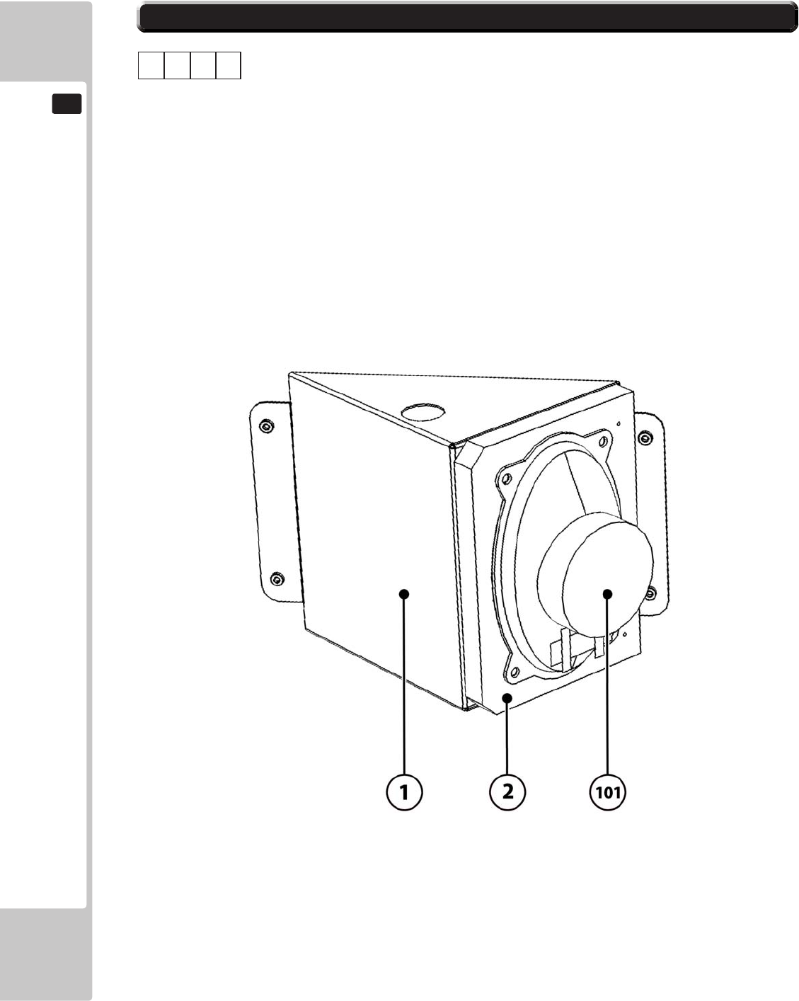
19-1 PARTS LIST SRS-1550UK 1/1
ASSY - SPEAKER L (SRS-1550UK)
1 1 2
No. Component Part Description Quantity
----- --------------------------------------------------- ---------------
1 SRS-1551UK SPEAKER BRKT 1
2 SRS-1552UK BLOCK SPACER SPEAKER 1
101 130-04030-E SPKR ELIP 4OHM 30W VIS DX4x6P 0.5
201 000-P00425-W M4X25 MSCR PAN W/FS PAS 4 *
202 012-P03512-F N6X1/2" S/TAP FLG PAS 2 *
* NOT SHOWN
ABCD
PARTS LIST
135
19
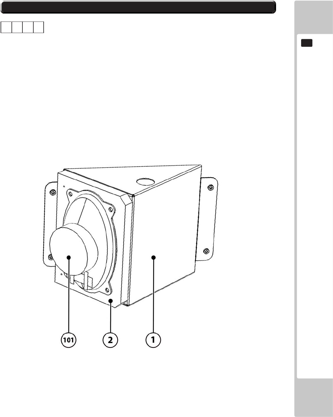
19-1 PARTS LIST SRS-1560UK 1/1
ASSY - SPEAKER R (SRS-1560UK)
1 1 3
No. Component Part Description Quantity
----- --------------------------------------------------- ---------------
1 SRS-1551UK SPEAKER BRKT 1
2 SRS-1552UK BLOCK SPACER SPEAKER 1
101 130-04030-E SPKR ELIP 4OHM 30W VIS DX4x6P 0.5
201 000-P00425-W M4X25 MSCR PAN W/FS PAS 4 *
202 012-P03512-F N6X1/2" S/TAP FLG PAS 2 *
* NOT SHOWN
ABCD

136
PARTS LIST
19
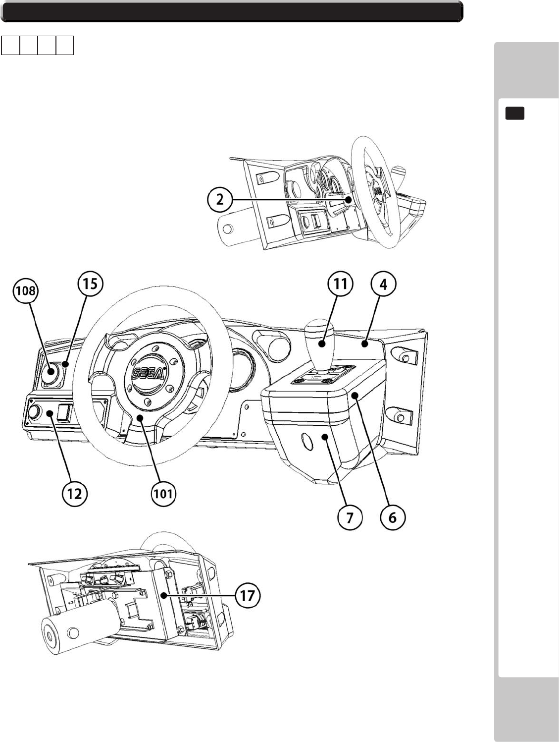
19-1 PARTS LIST SRS-2000UK 1/2
ASSY - CONTROL PANEL TWIN (SRS-2000UK)
1 1 4
No. Component Part Description Quantity
----- --------------------------------------------------- ---------------
2 SRS-2003UK HANDLE COLLAR 1
4 SRS-2001UK CONTROL PANEL COVER 1
5 SRS-2002UK CONTROL PANEL BRKT 1 *
6 INY-1204 SHIFT COVER INY 1
7 DYN-1223X SHIFT COVER B 1
9 LMN-1202 SHIFT BASE 1 *
11 610-0408-01 UP/DOWN SHIFTER AL YL 1
12 SRS-2100UK ASSY SW PLATE 1
14 SRS-0031UK STICKER CONTROL PANEL L 1 *
15 117-5164UK PLATE START 37x42 UK 1
16 DYN-0010UK DENOMI PLATE 1 *
17 SRS-2004UK CONTROL PANEL BACK 1
101 FR-2500-01UK MECHA 50-0102-08 W/SEGA CAP 1
102 280-A01200-A ROUTER TWIST D12 ADH 4 *
103 280-A02000-A ROUTER TWIST D20 ADH 1 *
108 509-5440 PUSH BTN SW IT GRN W/L DC 14V 1
202 060-F00800 M8 WSHR FORM A FLT PAS 4 *
204 050-U00800 M8 NUT NYLOK PAS 4 *
205 FAS-200013 M4X16 SKT CAP CRM 6 *
206 000-T00416-0B M4X16 MSCR TH BLK 3 *
207 000-P00412-W M4X12 MSCR PAN W/FS PAS 3 *
208 008-T00516-0B M5X16 TMP PRF TH BLK 4 *
210 030-000820-S M8X20 BLT W/S PAS 4 *
211 050-F00300 M3 NUT FLG SER PAS 2 *
212 000-T00412-0C M4X12 MSCR TH CRM 4 *
215 050-F00400 M4 NUT FLG SER PAS 2 *
216 000-T00416-0B M4X16 MSCR TH BLK 4 *
217 060-F00400-0B M4 WSHR FORM A FLT BLK 6 *
218 068-652016 M6 WSHR 20OD FLT PAS 4 *
219 050-U00600 M6 NUT NYLOK PAS 4 *
302 SRS-60021UK WH BTN PLATE 1 *
303 SRS-60017UK WH CNTL PNL EXTN 1 *
304 SRS-60018UK WH CREDIT BNTN EXTN 1 *
305 SRS-60019UK WH CREDIT BTN 1 *
306 SRS-60020UK WH SPEAKER B 2 *
309 SRS-60022UK WH SHIFTER EXTN 1 *
* NOT SHOWN
ABCD
PARTS LIST
137
19
19-1 PARTS LIST SRS-2000UK 2/2
ASSY - CONTROL PANEL TWIN (SRS-2000UK)
1 1 4
ABCD
138
PARTS LIST
19
19-1 PARTS LIST SRS-2001UK 1/1
ASSY - CONTROL PANEL COVER DX
1 1 4 4
No. Component Part Description Quantity
----- --------------------------------------------------- ---------------
1 SRG-1201X-D PANEL COVER MACHINED 1
2 SRS-2001-BUK METER PANEL 1
3 SRS-2001-CUK DESIGN PLATE L TWIN 1 *
4 SRS-2001-DUK DESIGN PLATE M TWIN 1 *
5 SRS-2001-EUK DESIGN PLATE R TWIN 1 *
201 047-PA3207-6 DIA 3.2X7.6 RVT OPEN AL 4 *
202 060-F00300 M3 WSHR FORM A FLT PAS 4 *
* NOT SHOWN
ABCD
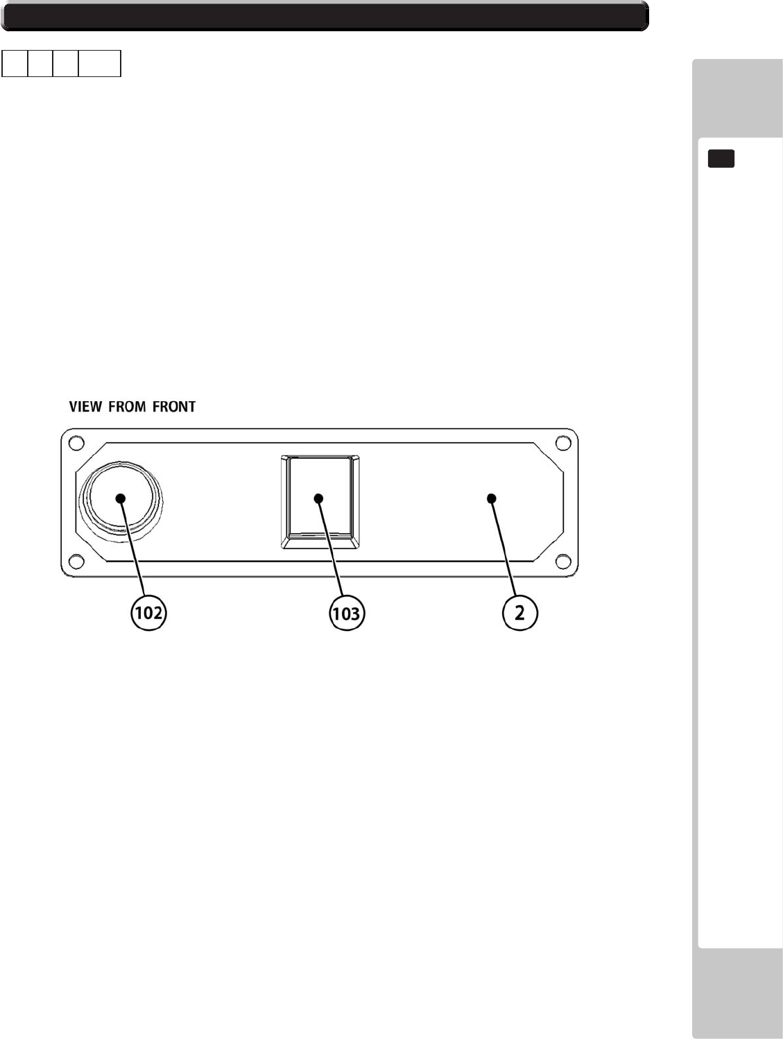
PARTS LIST
139
19
19-1 PARTS LIST SRS-2100UK 1/1
ASSY - CONTROL PANEL SW PLATE
1 1 4 12
No. Component Part Description Quantity
----- --------------------------------------------------- ---------------
1 SRS-2101UK STICKER START/VIEW 1 *
2 ORT-2101 BUTTON PLATE 1
3 171-6478B PC BD LIGHTING SWX5 1 *
101 212-5205-12 CONN JST M 12P RTA 1 *
102 509-5560-Y PB SW W/L 6V 1L Y LW1L-15VY 1
103 509-5561-S PB SW W/L 6V 5L R LW5L-15VS 1
* NOT SHOWN
ABCD

140
PARTS LIST
19
19-1 PARTS LIST SRS-1200UK 1/2
ASSY - PEDAL BASE SRS (SRS-1200UK)
1 1 6
No. Component Part Description Quantity
----- --------------------------------------------------- ---------------
1 SPG-2200-01 ASSY BRAKE & ACCELL 1
2 SRS-1201UK PEDAL BASE 1
3 TFF-1202UK FOOTREST BASE 1
4 SPG-2222UK ANTI FINGER TRAP PLATE LEFT 1 *
5 SPG-2223UK ANTI FINGER TRAP PLATE RIGHT 1
6 SPG-2224UK PEDAL GASKET 1 *
7 SRT-2031UK NEOPRENE RUBBER STRIP 10 0.52 *
8 SRS-1203XUK WIRE COVER BOX 1
101 280-A01200-A ROUTER TWIST D12 ADH 6 *
201 068-852216-0B M8 WSHR 22OD FLT BLK 4 *
202 030-000820-SB M8X20 BLT W/S BLK 4 *
203 030-000616-SB M6X16 BLT W/S BLK 4 *
204 050-F00400 M4 NUT FLG SER PAS 3 *
205 030-000816-S M8X16 BLT W/S PAS 4 *
206 060-F00800 M8 WSHR FORM A FLT PAS 4 *
207 060-F00600-0B M6 WSHR FORM A FLT BLK 4 *
301 1 *
* NOT SHOWN
ABCD
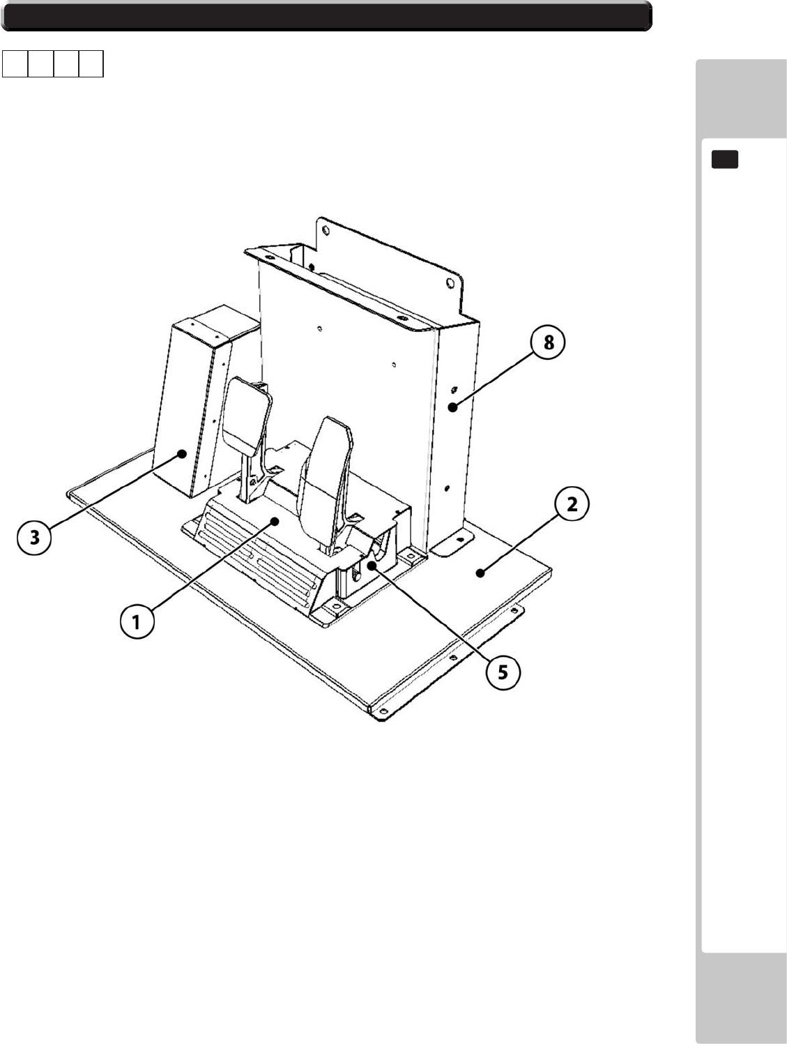
PARTS LIST
141
19
19-1 PARTS LIST SRS-1200UK 2/2
ASSY - PEDAL BASE SRS (SRS-1200UK)
1 1 6
ABCD
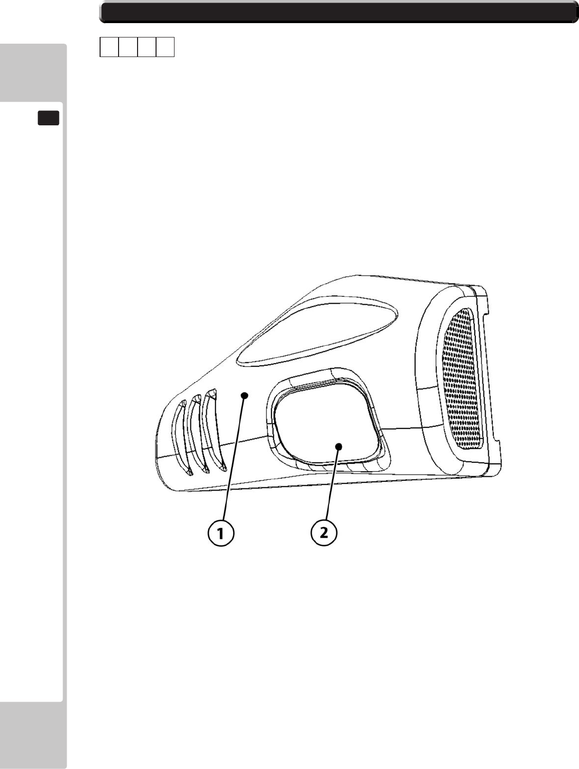
142
PARTS LIST
19
19-1 PARTS LIST SRS-1150UK 1/1
ASSY - SIDE POD L (SRS-1150UK)
1 1 7
No. Component Part Description Quantity
----- --------------------------------------------------- ---------------
1 SRS-1151UK SIDE POD L 1
2 SRS-1152UK STICKER SIDE POD 1
3 SRS-1153UK STICKER SIDE POD PIRELLI 1 *
* NOT SHOWN
ABCD
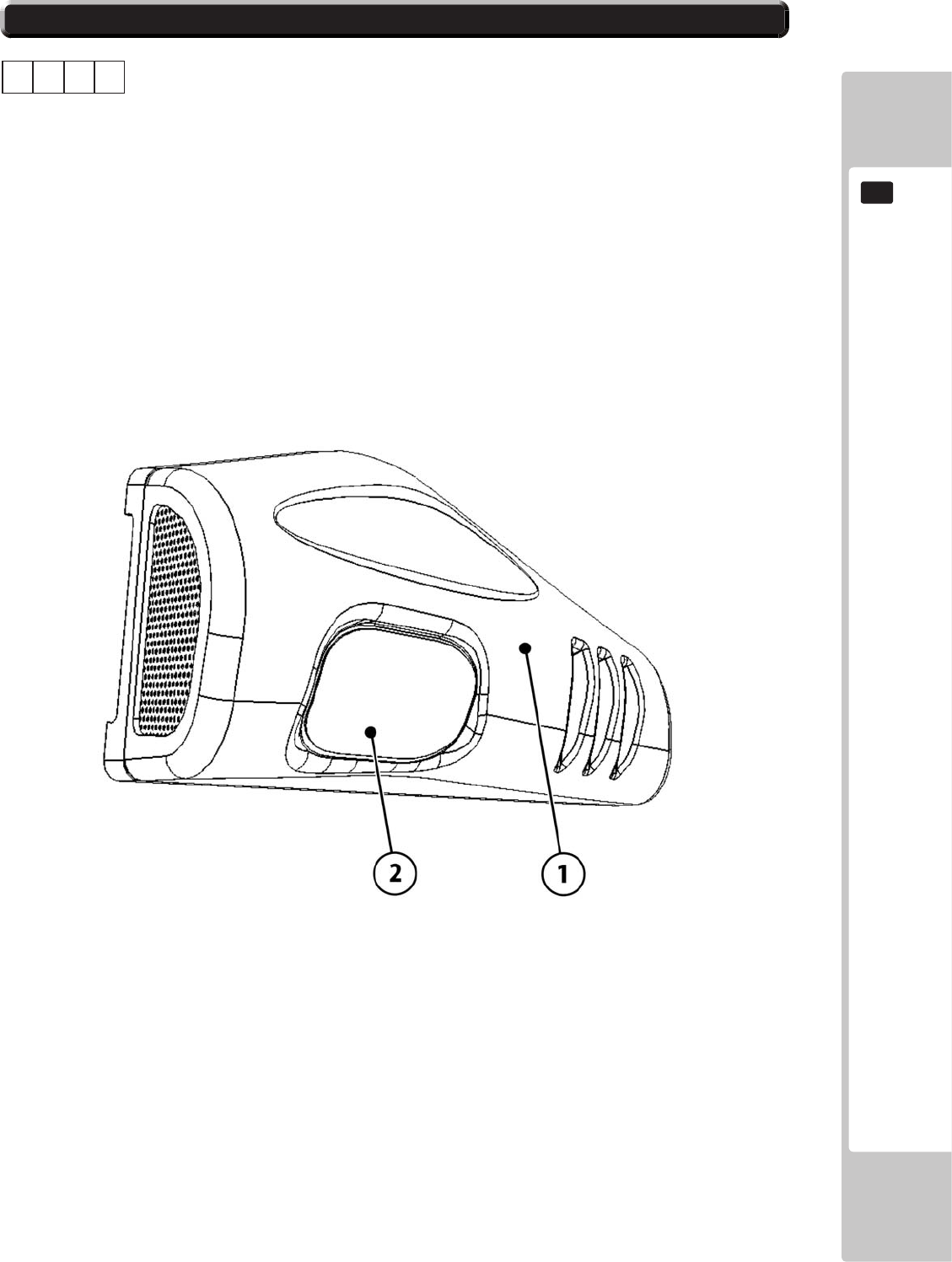
PARTS LIST
143
19
19-1 PARTS LIST SRS-1160UK 1/1
ASSY - SIDE POD R (SRS-1160UK)
1 1 8
No. Component Part Description Quantity
----- --------------------------------------------------- ---------------
1 SRS-1161UK SIDE POD R 1
2 SRS-1152UK STICKER SIDE POD 1
3 SRS-1153UK STICKER SIDE POD PIRELLI 1 *
* NOT SHOWN
ABCD

144
PARTS LIST
19
19-1 PARTS LIST SRS-1300UK 1/3
ASSY - BILLBOARD (SRS-1300UK)
1 1 11
No. Component Part Description Quantity
----- --------------------------------------------------- ---------------
1 SRS-1301UK BASE LIGHT UNIT 1
2 SRS-1320UK ASSY LIGHT UNIT L 1
3 SRS-1330UK ASSY LIGHT UNIT R 1
4 SRS-5050UK ASSY TRAY BULB R LEADER DX 1
5 SRS-1302UK COVER CCFL COMPARTMENT 1
6 SRS-1303UK COVER FL COMPARTMENT 1
18 LB1102 STICKER DANGEROUS VOLTAGE 1 *
19 LB1104 STICKER CAUTION, HOT SURFACE 1 *
20 421-7501-10 STICKER FL 40W 2 *
21 SRS-0253UK RETAINER RACE LEADER 1 *
22 SRS-0252UK RACE LEADER 1
101 390-0240-40UK FL TRAY 240V 40W 1
102 390-5695-40-DUK FL TUBE 40W 600L 1.5 1
103 838-0011UK LED HEADLAMP BD 2
201 050-F00400 M4 NUT FLG SER PAS 5 *
202 060-F00400 M4 WSHR FORM A FLT PAS 6 *
203 000-P00410-W M4X10 MSCR PAN W/FS PAS 12 *
204 000-T00412-0B M4X12 MSCR TH BLK 16 *
205 060-F00800 M8 WSHR FORM A FLT PAS 2 *
206 050-W00400 M4 NUT WING TYPE 2 PAS 2 *
301 SRS-60031UK WH FL UNIT 1 *
302 SRS-60032UK WH HEAD LAMPS 1 *
* NOT SHOWN
ABCD
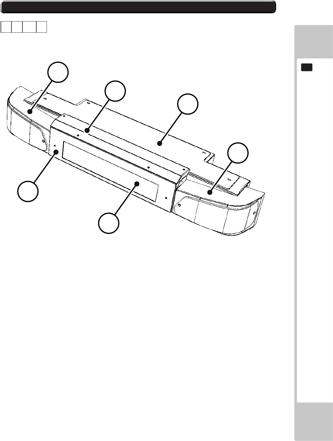
PARTS LIST
145
19
19-1 PARTS LIST SRS-1300UK 2/3
ASSY - BILLBOARD (SRS-1300UK)
1 1 11
1 SRS-1301UK BASE LIGHT UNIT 1
2 SRS-1320UK ASSY LIGHT UNIT L 1
3 SRS-1330UK ASSY LIGHT UNIT R 1
5 SRS-1302UK COVER CCFL COMPARTMENT 1
6 SRS-1303UK COVER FL COMPARTMENT 1
22 SRS-0252UK RACE LEADER 1
ABCD
1
2
3
56
22
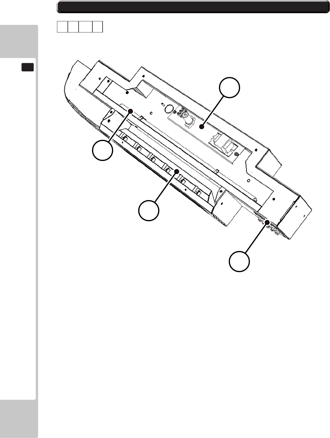
146
PARTS LIST
19
19-1 PARTS LIST SRS-1300UK 3/3
ASSY - BILLBOARD (SRS-1300UK)
1 1 11
ABCD
101
102
103
4
4 SRS-5050UK ASSY TRAY BULB R LEADER DX 1
101 390-0240-40UK FL TRAY 240V 40W 1
102 390-5695-40-DUK FL TUBE 40W 600L 1.5 1
103 838-0011UK LED HEADLAMP BD 2
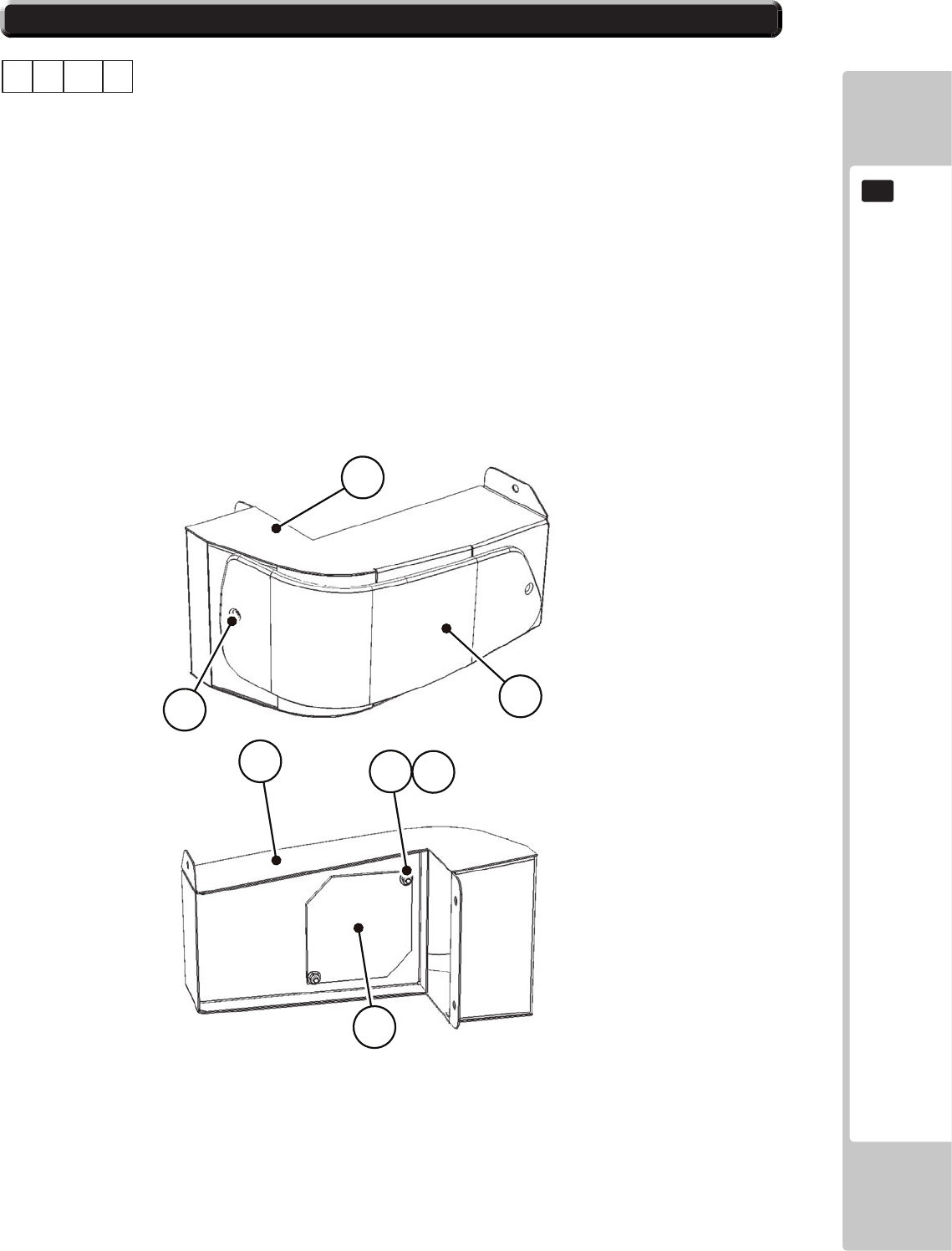
PARTS LIST
147
19
19-1 PARTS LIST SRS-1320UK 1/2
ASSY - LIGHT UNIT L (SRS-1320UK)
1 1 11 2
No. Component Part Description Quantity
----- --------------------------------------------------- ---------------
1 SRS-1321UK LIGHT UNIT L 1 *
2 SRS-3508UK TAIL LIGHT LENS OUTER L 1 *
3 SRS-3552UK PRSIM LENS TAIL LIGHT 1 *
201 008-T00412-0B M4X12 TMP PRF TH BLK 2 *
202 050-F00400 M4 NUT FLG SER PAS 2 *
203 060-F00400 M4 WSHR FORM A FLT PAS 2 *
* NOT SHOWN
ABCD
202 203
1
3
201
1
2
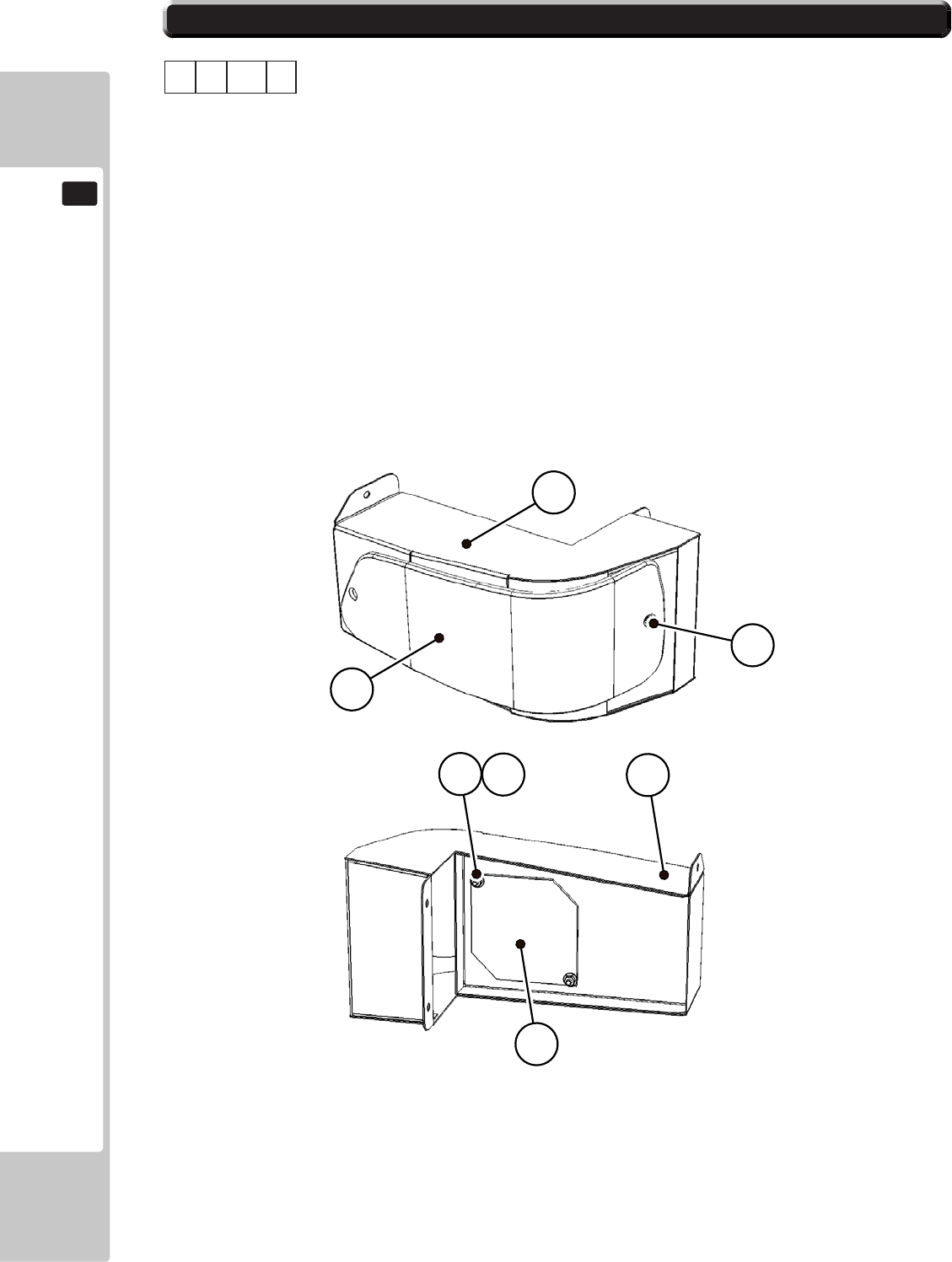
148
PARTS LIST
19
19-1 PARTS LIST SRS-1330UK 1/1
ASSY - LIGHT UNIT R (SRS-1330UK)
1 1 11 3
No. Component Part Description Quantity
----- --------------------------------------------------- ---------------
1 SRS-1331UK LIGHT UNIT R 1 *
2 SRS-3509UK TAIL LIGHT LENS OUTER R 1 *
3 SRS-3552UK PRSIM LENS TAIL LIGHT 1 *
201 008-T00412-0B M4X12 TMP PRF TH BLK 2 *
202 050-F00400 M4 NUT FLG SER PAS 2 *
203 060-F00400 M4 WSHR FORM A FLT PAS 2 *
* NOT SHOWN
ABCD
202 203 1
3
201
1
2
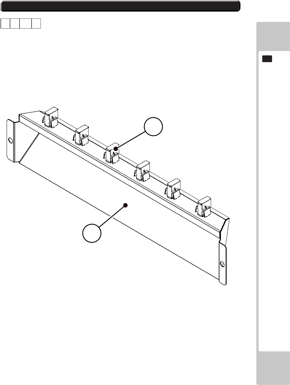
PARTS LIST
149
19
19-1 PARTS LIST SRS-5050UK 1/1
ASSY - TRAY BULB Race Leader (SRS-5050UK)
1 1 11 4
No. Component Part Description Quantity
----- --------------------------------------------------- ---------------
1 SRS-5051UK TRAY BULB R LEADER DX 1
301 SRS-65074UK WH RACE LEADER 1 *
* NOTE '301' Consists of all 6 Bulb Holders, Bulbs and Wiring Harness.
ABCD
1
301

150
PARTS LIST
19
19-1 PARTS LIST SRS-1600UK 1/2
ASSY - SEAT TWIN 1P (SRS-1600UK)
1 1 13
No. Component Part Description Quantity
----- --------------------------------------------------- ---------------
4 253-5550UK-21B PAN SEAT W LOGO SEGA BLACK 1
5 ABX-2403UK SEAT BASE 1
7 SRS-1604UK SEAT FRAME 1
8 SRS-1606UK SEAT MOUNT TRAY 1
12 ABX-2410UK SAFETY GUARD 1 *
13 SRS-1611UK CABLE BEAR BRKT 1 *
14 STC-1612 PROTECT RUBBER 2 *
15 ABX-2413UK SAFETY GUARD F 1
16 OS1004 DRAFT EXCLDR 4 X7MM BLK x 10M 1 *
17 SRS-1601UK HEADREST CUSHION 1
19 SRS-1602UK HEADREST REAR 1
22 SRS-1602-BUK STICKER HEADREST REAR 1 *
23 SRS-1603UK STICKER SEAT BACK 1 *
31 SRS-2500UK ASSY HAND BRAKE 1 *
32 SRS-1651UK HANDBRAKE ENCLOSURE 1
33 SRS-2501UK SRS HANDBRAKE HANDLE 1
34 SRS-1618UK END PLUG 2 *
35 SRS-1608UK BRKT HEADREST REAR BTM 1 *
36 SRS-1609UK BRKT HEADREST REAR TOP 2 *
101 601-9059-91 SEAT RAIL L 1
102 601-9060-91 SEAT RAIL R 1
108 601-6981-009 CABLE BEAR L=009 1 *
202 068-852216 M8 WSHR 22OD FLT PAS 14 *
203 030-000820-S M8X20 BLT W/S PAS 6 *
204 000-P00410-W M4X10 MSCR PAN W/FS PAS 2 *
205 000-T00408-0B M4X8 MSCR TH BLK 8 *
207 050-U00800 M8 NUT NYLOK PAS 8 *
209 000-T00616-0B M6X16 MSCR TH BLK 4 *
210 030-000620-S M6X20 BLT W/S PAS 8 *
211 068-652516 M6 WSHR 25OD FLT PAS 4 *
212 000-T00512-0C M5X12 MSCR POSI TH CRM 5 *
213 000-P00512-W M5X12 MSCR PAN W/FS PAS 4 *
214 050-F00400 M4 NUT FLG SER PAS 4 *
215 028-00405-B M4X5 GSCR SKT CUP BLK 1 *
216 050-F00600 M6 NUT FLG SER PAS 6 *
218 068-852216-0B M8 WSHR 22OD FLT BLK 4 *
219 030-000820-SB M8X20 BLT W/S BLK 4 *
301 SRS-60024UK WH HANDBRAKE A 1 *
302 SRS-60025UK WH CABLE BEAR 1 *
* NOT SHOWN
ABCD
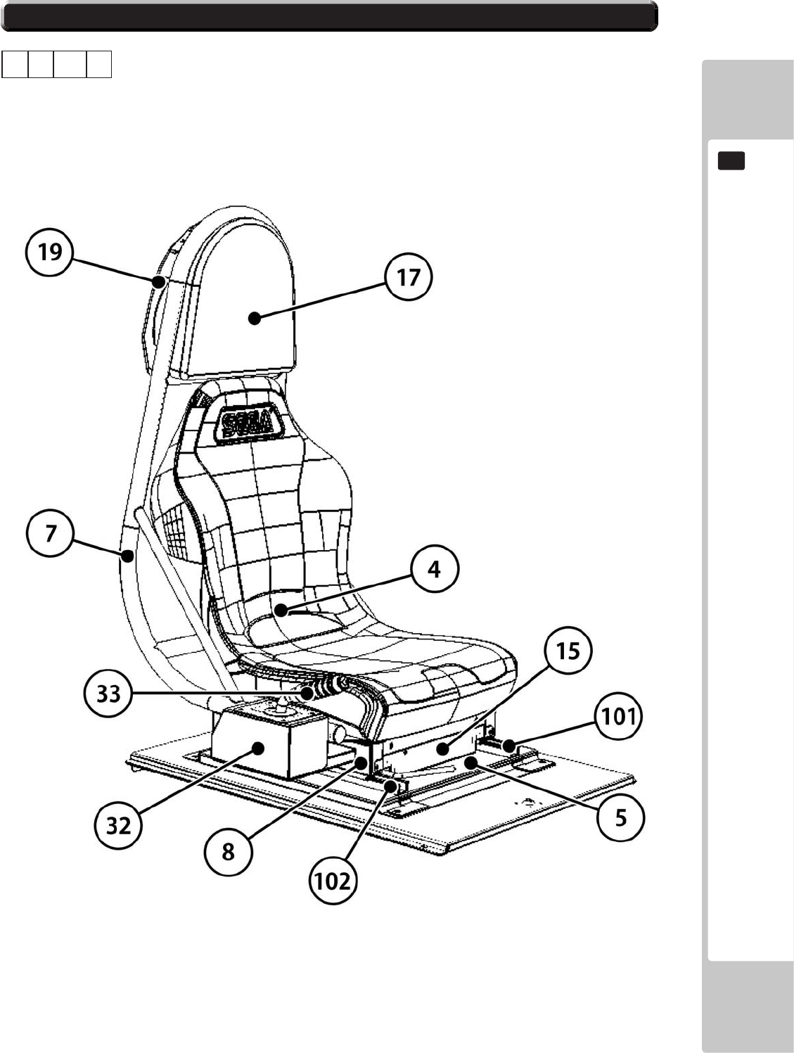
PARTS LIST
151
19
19-1 PARTS LIST SRS-1600UK 2/2
ASSY - SEAT TWIN 1P (SRS-1600UK)
1 1 13
No. Component Part Description Quantity
----- --------------------------------------------------- ---------------
ABCD
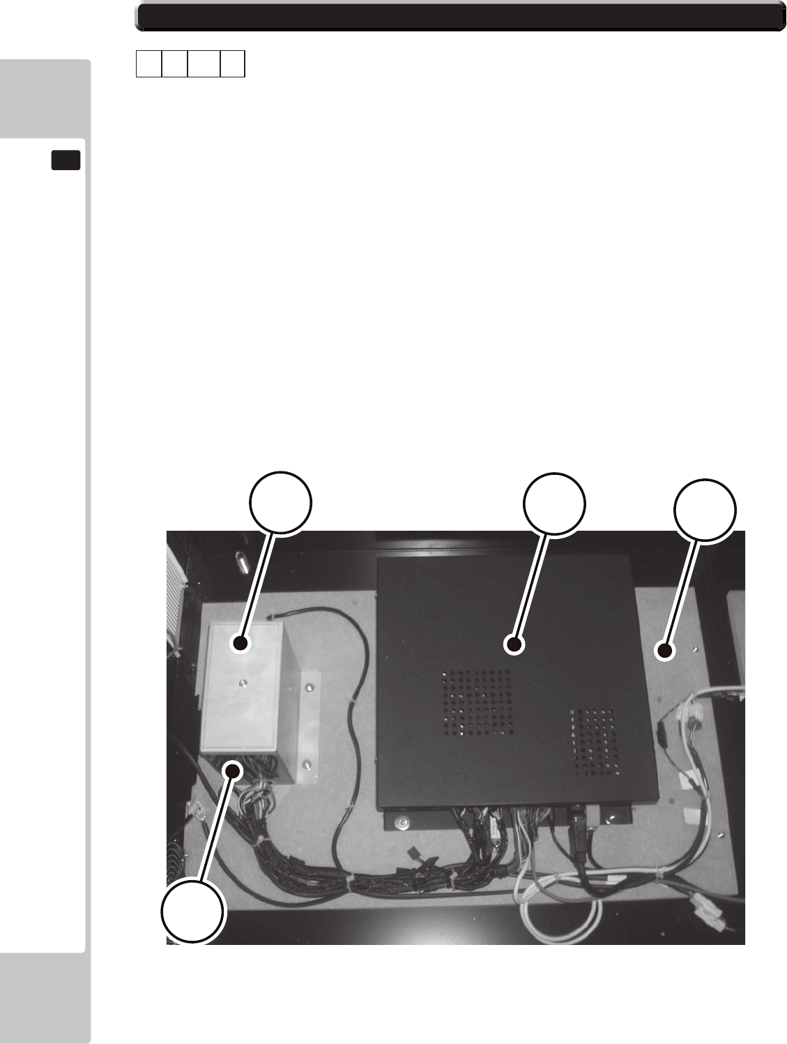
152
PARTS LIST
19
19-1 PARTS LIST SRS-4500UK 1/1
ASSY - MAIN BOARD (SRS-4500UK)
1 1 14
No. Component Part Description Quantity
----- --------------------------------------------------- ---------------
1 SRS-4501UK MAIN BD BASE 1
2 SRS-4204UK BRKT MTG SUPPLY BFG 1
5 LB1111 STICKER PLEASE RECYCLE 1 *
101 400-5457-500UK FSP ATX PSU 1
102 610-0003-01UK ASSY CASE EUROPA SRS 1
106 280-A02064-WX ROUTER TWIST D20 SO6.4 WOOD X 16 *
107 LB1101 STICKER WARNING BATTERY 1 *
112 EP2001-01BL DK SRSTW EU BLUE 1 *
201 000-P00416-W M4X16 MSCR PAN W/FS PAS 6 *
301 SRS-60014UK WH P PORT B 1 *
302 SRS-60015UK WH AUDIO B 1 *
303 SRS-60016UK WH AC GAMEBOARD 1 *
304 SRS-60026UK WH HANDBRAKE B 1 *
305 SRS-60033UK WH FAN EXT 240V 1 *
306 SRS-60034UK WH EUROPA POWER 1 *
* NOT SHOWN
ABCD
1
2
101
102

PARTS LIST
153
19
19-1 PARTS LIST SRS-4600UK 1/2
ASSY - ELEC BD (SRS-4600UK)
1 1 15
No. Component Part Description Quantity
----- --------------------------------------------------- ---------------
1 SRS-4601UK WOODEN BASE ELEC 1
2 CFB-4003-01UK EARTH TERMINAL PLATE 1
201 012-P03512-F N6X1/2" S/TAP FLG PAS 2 *
103 838-0005UK I/O BOARD SAE 1
104 838-14515-A03 SOUND AMP ANALOG IN W/EXP BD 1
105 FR-838-001UK MOTOR CONT HAPP 50-2000-03 1
106 400-065-0512-01 PSU 5V/12V DC 65W MW RPD-65C 1
107 400-075-024-01 PSU 24VDC 75W MW LPS-75-24 1
108 400-050-024-01 PSU 24VDC 50W MW LPS-50-24 1
109 838-14551-02UK AC DISTRIBUTION BD 1
110 838-0012UK LAMP DRV BOARD 1
111 OS1011 PCB FEET RICHCO LCBS-L-5-01 16 *
115 280-A01264-WX ROUTER TWIST D12 SO6.4 WOOD X 14 *
116 280-A02064-WX ROUTER TWIST D20 SO6.4 WOOD X 10 *
201 012-P03512-F N6X1/2" S/TAP FLG PAS 2 *
202 012-P00325 N4X1" S/TAP FLG PAS 16 *
203 012-P03506-F N6X1/4" S/TAP FLG PAS 16 *
301 SRS-60004UK WH AC ELEC BRD 1 *
302 SRS-60005UK WH AC EXT ELEC BASE 1 *
303 SRS-60006UK WH DC I/O 1 *
304 SRS-60007UK WH DC AMP 1 *
305 SRS-60008UK WH DC MOTOR CONTROL 1 *
306 SRS-60009UK WH DC MOTOR OUT 1 *
307 SRS-60010UK WH SPEAKER A 1 *
308 SRS-60011UK WH AUDIO A 1 *
309 SRS-60012UK WH P PORT A 1 *
310 SRS-60013UK WH I/O 1 *
311 600-7141-100UK CABLE JVS TYPE A-B 100cm 1 *
* NOT SHOWN
ABCD
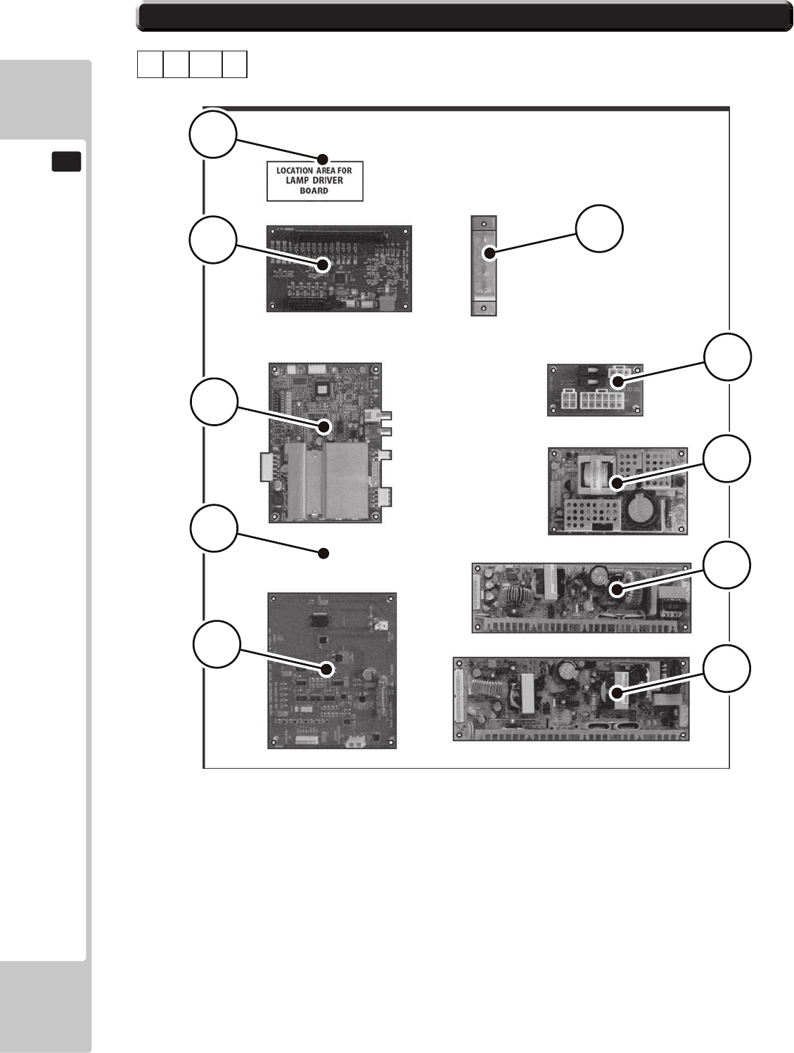
154
PARTS LIST
19
19-1 PARTS LIST SRS-4600UK 2/2
ASSY - ELEC BD (SRS-4600UK)
1 1 15
ABCD
104
103
1
2
105
106
107
108
109
110
1 SRS-4601UK WOODEN BASE ELEC 1
2 CFB-4003-01UK EARTH TERMINAL PLATE 1
103 838-0005UK I/O BOARD SAE 1
104 838-14515-A03 SOUND AMP ANALOG IN W/EXP BD 1
105 FR-838-001UK MOTOR CONT HAPP 50-2000-03 1
106 400-065-0512-01 PSU 5V/12V DC 65W MW RPD-65C 1
107 400-075-024-01 PSU 24VDC 75W MW LPS-75-24 1
108 400-050-024-01 PSU 24VDC 50W MW LPS-50-24 1
109 838-14551-02UK AC DISTRIBUTION BD 1
110 838-0012UK LAMP DRV BOARD 1
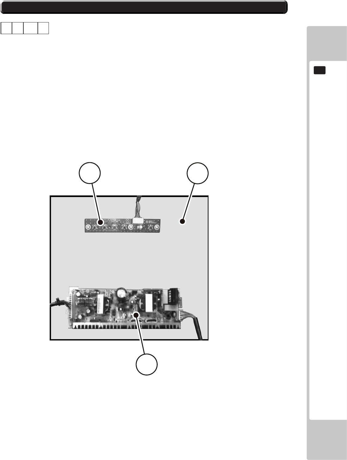
PARTS LIST
155
19
19-1 PARTS LIST SRS-4700UK 1/1
ASSY - PSU LCD BD (SRS-4700UK)
1 1 16
No. Component Part Description Quantity
----- --------------------------------------------------- ---------------
1 SRS-4701UK LCD ELEC BD 1
101 280-l00709-OS STANDOFF 70OD 41D 9L 3 *
105 280-A01264-WX ROUTER TWIST D12 SO6.4 WOOD X 6 *
201 012-P00320 N4X3/4" S/TAP PAN PAS 3 *
202 012-P03512-F N6X1/2" S/TAP FLG PAS 4 *
301 SRS-60030UK WH LCD PSU 1 *
A PSU 24VDC 150W MW LPS-150-24 1
B SATALITE ADJUSTMENT BOARD 1
* NOT SHOWN
ABCD
A
1B
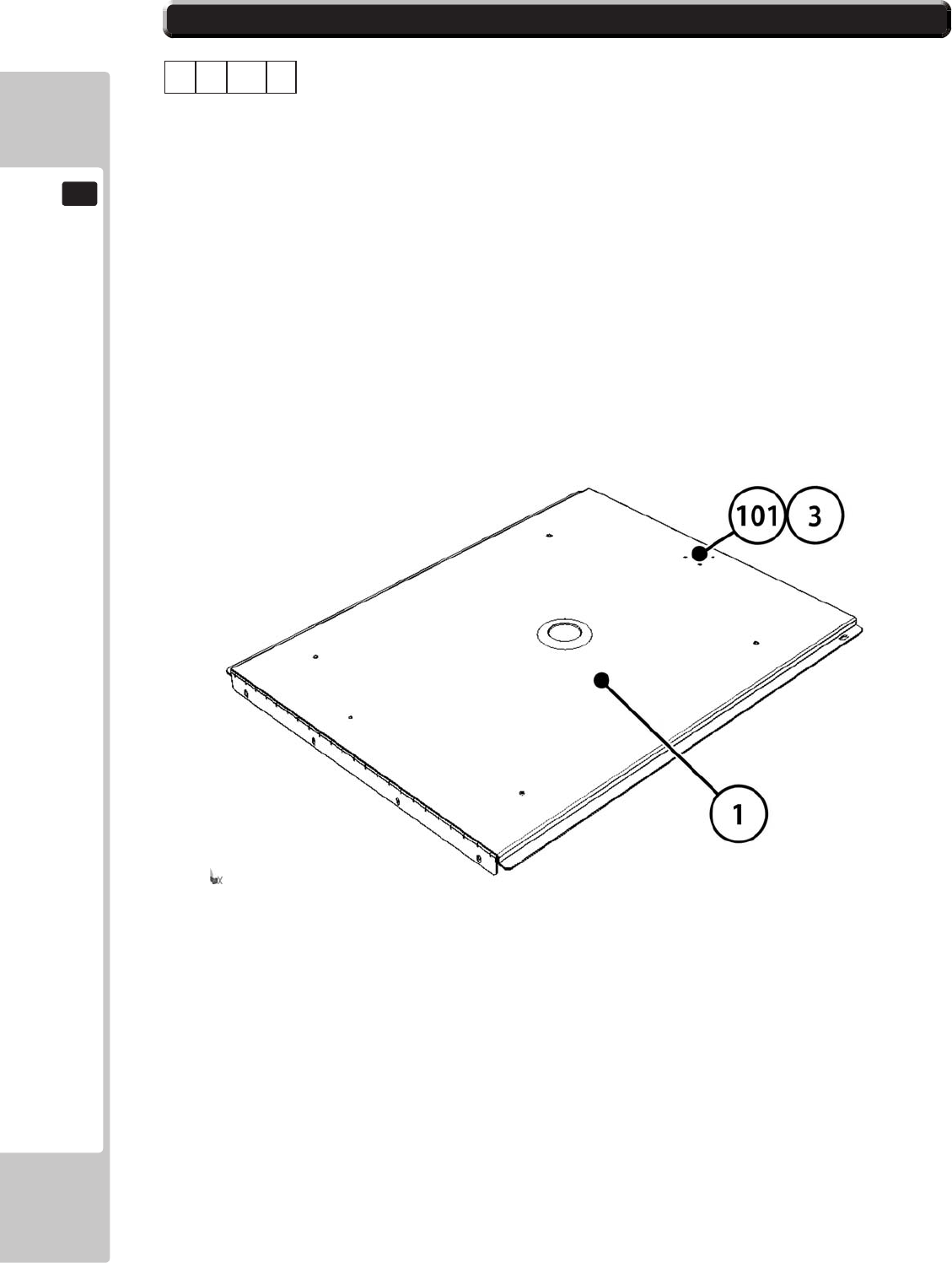
156
PARTS LIST
19
19-1 PARTS LIST SRS-1510UK 1/1
ASSY - BASE LID R (SRS-1510UK)
1 1 17
No. Component Part Description Quantity
----- --------------------------------------------------- ---------------
1 SRS-1511UK BASE LID R 1
2 DUT-1511-CUK GASKET STRIP 1 *
3 DUT-1511-DUK LOCK TONGUE DUT 1
101 220-5575UK LOCK 1
104 280-A00748-P M ROUTER TWIST D7 SO4.8 PANEL M 4 *
201 050-F00400 M4 NUT FLG SER PAS 1 *
301 600-9020-44K WIRE HARN EARTH 200mm M4/M4 K 1 *
* NOT SHOWN
ABCD
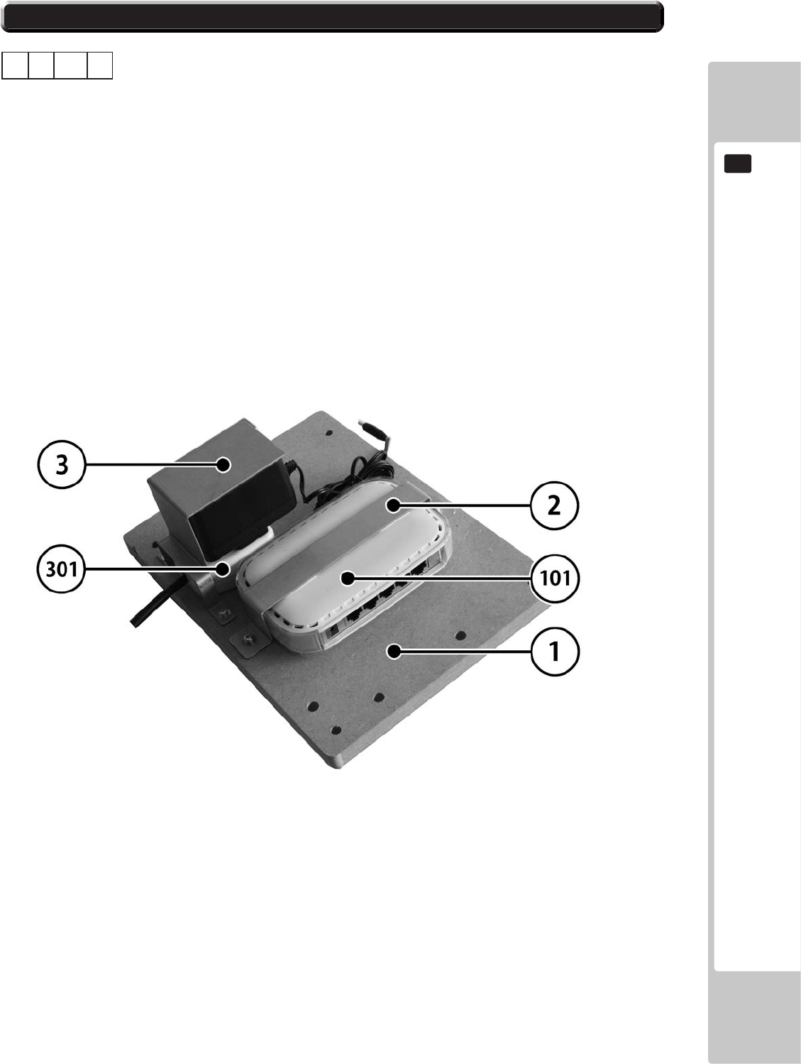
PARTS LIST
157
19
19-1 PARTS LIST SRS-4800UK 1/1
ASSY - HUB BD (SRS-4800UK)
1 2
No. Component Part Description Quantity
----- --------------------------------------------------- ---------------
1 SRS-4801UK WOODEN BASE HUB 1 *
2 SRS-4402UK BRKT HUB MTG 1 *
3 SRS-4801UK BRKT HUB PSU MTG 1 *
101 601-FS605 HUB ETHERNET 1 *
102 600-7269-0050UK LAN CABLE 50CM PALFB05BL 2 *
105 280-A01264-WX ROUTER TWIST D12 SO6.4 WOOD X 6 *
201 000-P004 12-W M4X12 MSCR PAN W/FS PAS 4 *
301 SRS-65069UK WH HUB POWER 1 *
* NOT SHOWN
ABCD

158
PARTS LIST
19
19-1 PARTS LIST SRS-0400UK 1/2
ASSY - AC BRKT MAIN (SRS-0400UK)
1 4
No. Component Part Description Quantity
----- --------------------------------------------------- ---------------
1 SRS-0401UK AC BRKT MAIN 1
3 LB1096 STICKER PROTECTIVE EARTH 1
101 EP1382 FILTER SCHAFFNER FN682-10/06 1
102 EP1387 IEC INLET & SW BZV01/Z0000/70 1
104 514-5078-10000 FUSE 5X20 CERAMIC SB 10000mA 1
105 421-6595-10000T STICKER FUSE 10000mA TYPE T 1 *
106 421-6595-5000-T STICKER FUSE 5000mA TYPE T 1 *
108 310-5029-D508 HEAT SHRINK SLEEVING 50.8DIA 4 *
111 EP1334 FUSE HOLDER 20mm 10A 240Vac 1
112 514-5078-5000 FUSE 5X20 CERAMIC SB 5000mA 1
113 LB1126-5-250 FUSE LABEL 5A 250V 1
114 LB1126-10-250 FUSE LABEL 10A 250V 1
201 000-P00308-W M3X8 MSCR PAN W/FS PAS 4 *
202 050-F00400 M4 NUT FLG SER PAS 5 *
301 SRS-60001UK WH AC IN A 1 *
302 SRS-60002UK WH AC IN B 1 *
* NOT SHOWN
ABCD
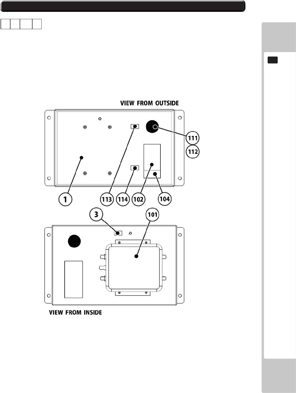
PARTS LIST
159
19
19-1 PARTS LIST SRS-0400UK 2/2
ASSY - AC BRKT MAIN (SRS-0400UK)
1 4
ABCD
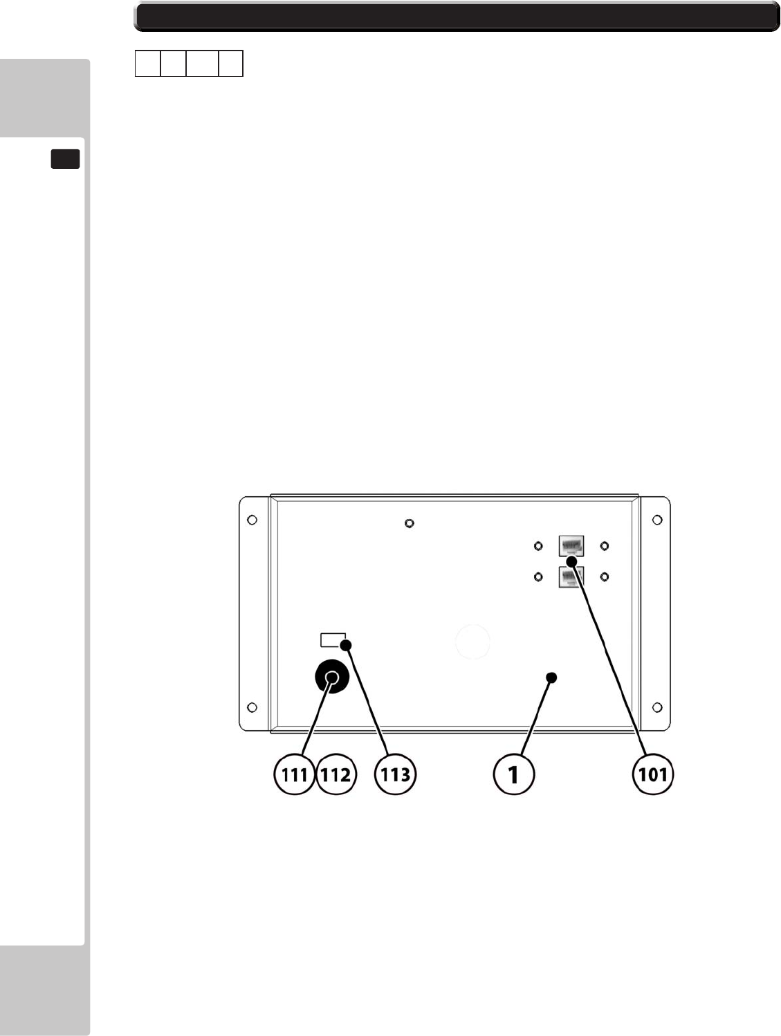
160
PARTS LIST
19
19-1 PARTS LIST SRS-0700UK 1/1
ASSY - AC BRKT SUB (SRS-0700UK)
1 5
No. Component Part Description Quantity
----- --------------------------------------------------- ---------------
1 SRS-0701UK AC BRKT SUB 1
2 TFF-0402UK CONN COVER 2 *
3 LB1096 STICKER PROTECTIVE EARTH 1 *
101 EP1391 COUPLER INLINE LAN RJ45 UTP CODE 1
106 421-6595-5000-T STICKER FUSE 5000mA TYPE T 1 *
111 EP1334 FUSE HOLDER 20mm 10A 240Vac 1
112 514-5078-5000 FUSE 5X20 CERAMIC SB 5000mA 1
113 LB1126-5-250 FUSE LABEL 5A 250V 1
202 050-F00400 M4 NUT FLG SER PAS 7 *
203 000-P00408-WB M4X8 MSCR PAN W/FS BLK 4 *
* NOT SHOWN
ABCD

PARTS LIST
161
19
19-1 PARTS LIST SRS-INST-KIT 1/2
INSTALLATION KIT SRS TWIN (SRS-INST-KIT)
1 3
No. Component Part Description Quantity
----- --------------------------------------------------- ---------------
2 SRS-0300UK ASSY COINCHUTE TOWER SRS TW 1
3 SRS-0022UK WIRE COVER SRS TWIN 1
4 SRS-0023UK JOINT PIPE 1
5 EP1391 COUPLER INLINE LAN RJ45 1 *
13 PK0449 INST KIT BOX SRS TWIN 1 *
21 SRS-0013UK POP CENTRE SRS TW 1
22 SRS-0014UK POP L SRS TW 1
23 SRS-0015UK POP R SRS TW 1
24 SRS-0016UK BRKT STRADDLE CENTRE POP 1
25 SRS-0017UK BRACE REAR CENTRE POP 1
26 SRS-0018UK BRKT SUPPORT L POP 1
27 SRS-0019UK BRKT SUPPORT R POP 1
28 SRS-0029UK PLATE BACKING INFILL 1 *
29 SRS-0030UK STICKER INFILL 1 *
30 SRS-0032UK STICKER SEAT NUMBERS 1 *
101 440-CS0186UK STICKER C EPILEPSY MULTI 2 *
104 LM1227 UK MAINS LEAD 10A WITH PLUG 1 *
105 LM1246 EUROLEAD 10A EUROPEAN SOCKET 1 *
106 600-7269-0500UK CA LAN CAT5 500CM 1 *
201 030-000825-SB M8X25 BLT W/S BLK 12 *
202 O68-852216-OB M8 WSHR 22OD FLT BLK 12 *
203 000-P00412-W M4X12 MSCR PAN W/FS PAS 4 *
204 000-P00612-W M6X12 MSCR PAN W/FS PAS 2 *
205 000-T00416-OB M4X16 MSCR TH BLK 8 *
205 068-441616-OB M4 WSHR 16OD FLT BLK 4 *
207 068-441616 M4 WSHR 16OD FLT PAS 4 *
208 050-F00400 M4 NUT FLT SER PAS 6 *
209 030-000616-SB M6X16 BLT W/S BLK 8 *
210 060-F00600-OB M6 WSHR FORM A FLT BLK 8 *
211 008-T00412-0C M4X12 TMP PRF TH CRM 4 *
212 068-441616-0C ME WASHER 16OD FLT CRM 4 *
301 SRS-60028UK WH POWER SLAVE 1 *
302 600-7269-0100UK CA LAN CAT5 100CM 2 *
402 420-0005-02UK SERVICE MANUAL SRS TW 1 *
403 OS1019 SELF SEAL BAG 9X12.3/4 2 *
408 SAECE-xxx DECLARATION OF CONFORMITY 1 *
* NOT SHOWN
ABCD
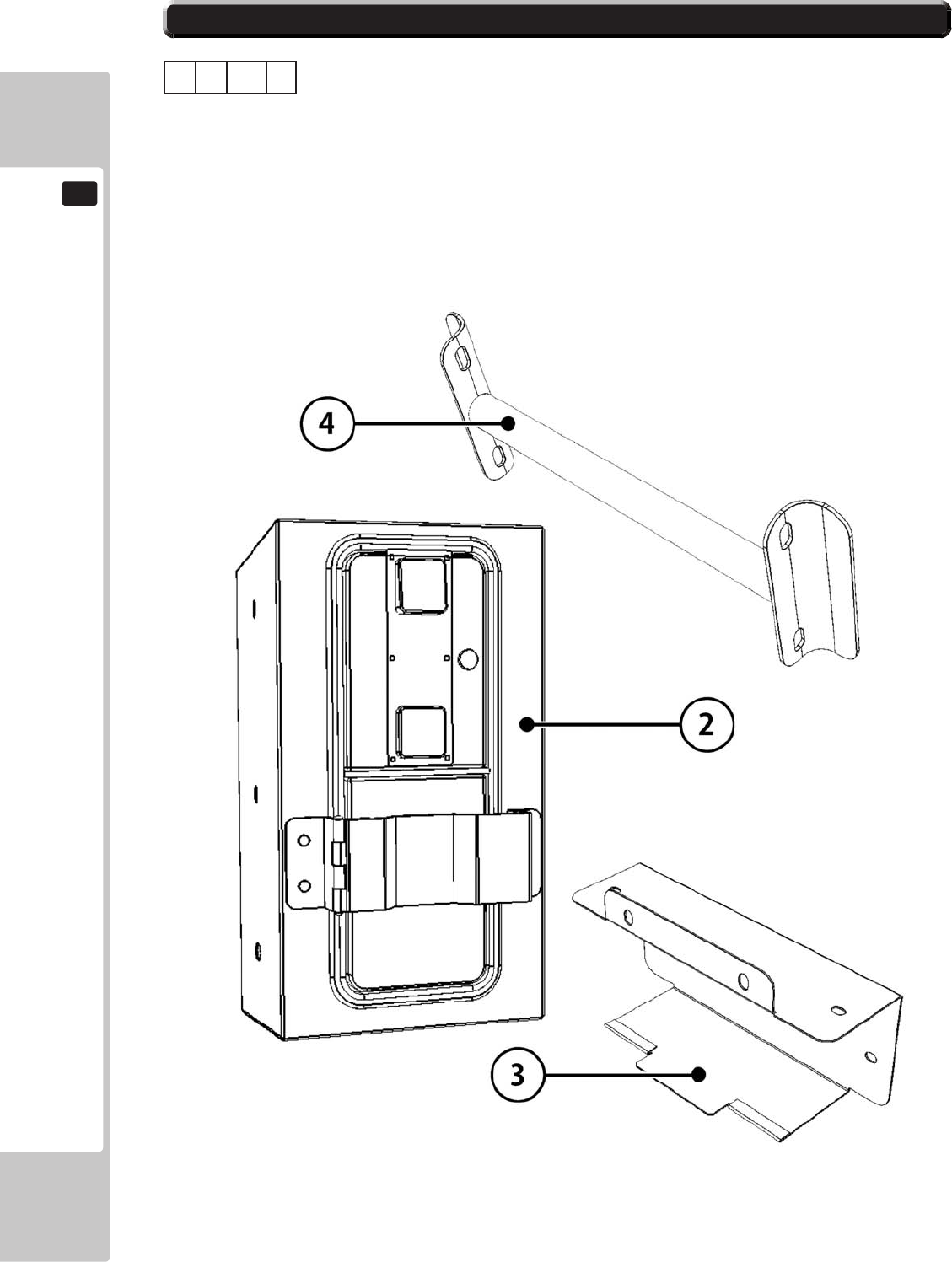
162
PARTS LIST
19
19-1 PARTS LIST SRS-INST-KIT 2/3
INSTALLATION KIT SRS TWIN (SRS-INST-KIT)
1 3
2 SRS-0300UK ASSY COINCHUTE TOWER SRS TW 1
3 SRS-0022UK WIRE COVER SRS TWIN 1
4 SRS-0023UK JOINT PIPE 1
ABCD
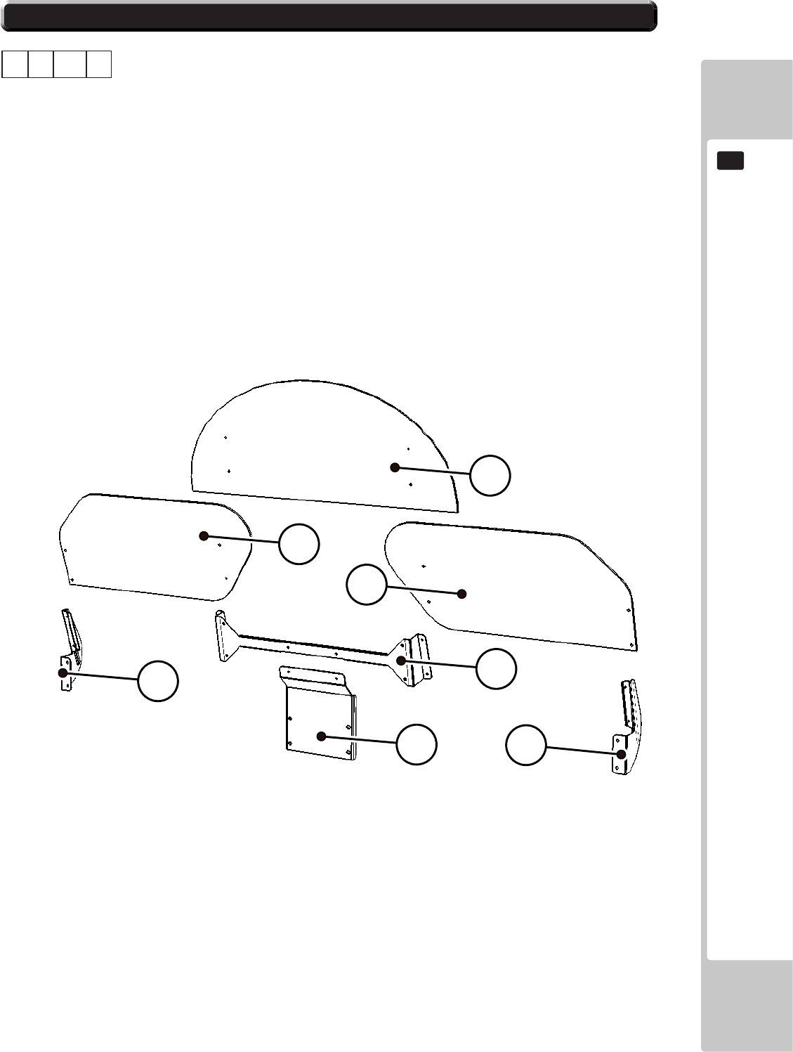
PARTS LIST
163
19
19-1 PARTS LIST SRS-INST-KIT 3/3
INSTALLATION KIT SRS TWIN (SRS-INST-KIT)
1 3
21 SRS-0013UK POP CENTRE SRS TW 1
22 SRS-0014UK POP L SRS TW 1
23 SRS-0015UK POP R SRS TW 1
24 SRS-0016UK BRKT STRADDLE CENTRE POP 1
25 SRS-0017UK BRACE REAR CENTRE POP 1
26 SRS-0018UK BRKT SUPPORT L POP 1
27 SRS-0019UK BRKT SUPPORT R POP 1
28 SRS-0029UK PLATE BACKING INFILL 1
ABCD
21
22
23
24
25
26
27
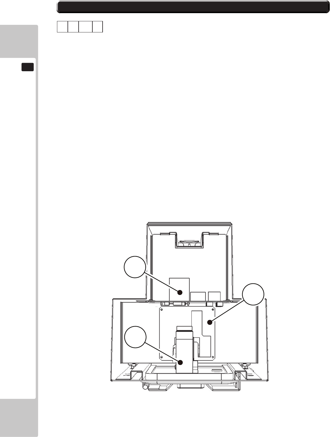
164
PARTS LIST
19
19-1 PARTS LIST SRS-0300UK 1/2
ASSY - COIN CHUTE TOWER (SRS-0300UK)
1 3 2
No. Component Part Description Quantity
----- --------------------------------------------------- ---------------
1 SRS-0301UK COIN CHUTE TOWER SRS 1
2 VTS-FRI-T-R VTS BOARD FRI TWIN 1
3 PP1087 BOX CASH FOR MINI DOOR 1 *
6 DUT-0302UK COIN PATH PLATE 1
10 SRS-0302UK CCT FLOOR 1 *
11 LB1103 STICKER CAUTION 2 *
12 SRS-0304UK LOCKING HASP 1
13 SRS-0305UK BRKT PADLOCK 1
102 220-5374-01 DOOR DFMD W/FR&LOCK C120 UNIV 1
103 220-5574UK LOCK KEYED DIFFERENT 7087-10 1
105 220-5610-01 SR3 STD BODYBSR3INGB 1
106 220-5727-01B DOOR CASH H.S. STS 1
201 000-P00410-W M4X10 MSCR PAN W/FS PAS 11 *
202 050-F00400 M4 NUT FLG SER PAS 2 *
204 050-U00800 M8 NUT NYLOK PAS 4 *
205 068-852216 M8 WSHR 22OD FLT PAS 4 *
301 SRS-60027UK WH VTS TWN 1 *
302 LM1006LOR LOOM COIN MECH LAMP 1 *
* NOT SHOWN
ABCD
105
2
6
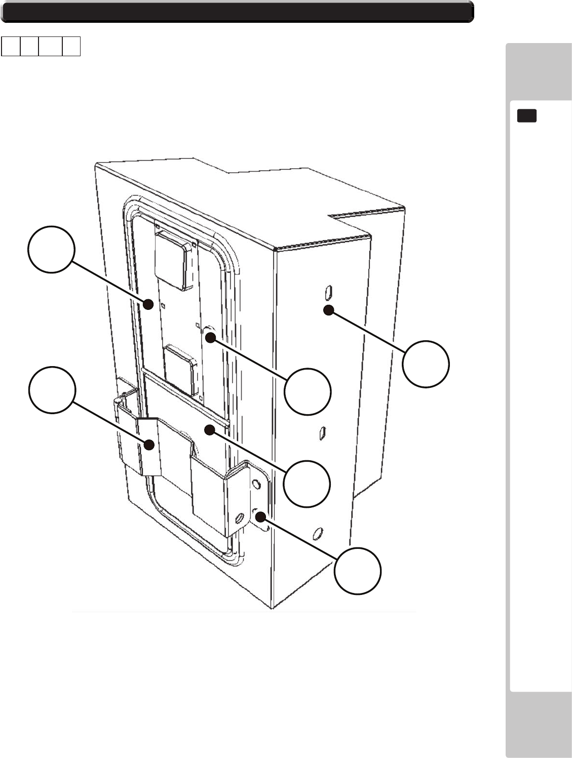
PARTS LIST
165
19
106
12
13
1
103
102
19-1 PARTS LIST SRS-0300UK 2/2
ASSY - COIN CHUTE TOWER (SRS-0300UK)
1 3 2
ABCD

166
PARTS LIST
19
NOTES ON PARTS LIST
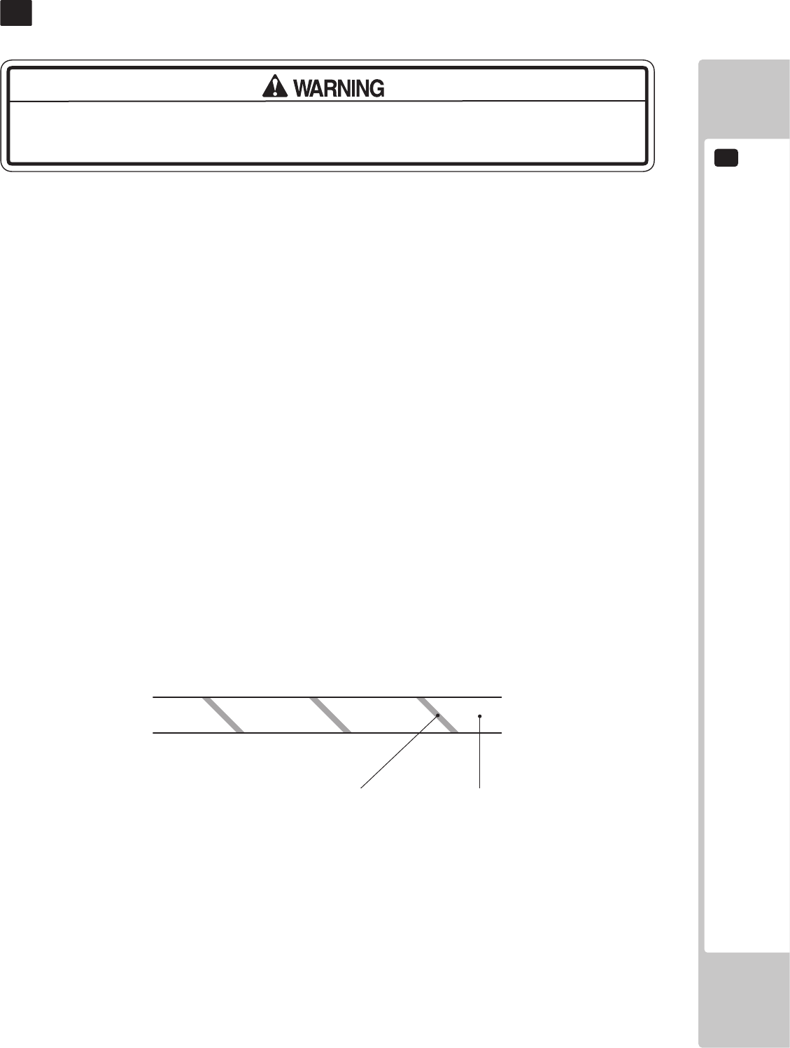
WIRE COLOUR CODE TABLE
20
167
The DC power wire color for this product is dierent from previous SEGA titles. Working
from the previous wire colors will create a high risk of re.
WIRECOLORCODETABLE
20
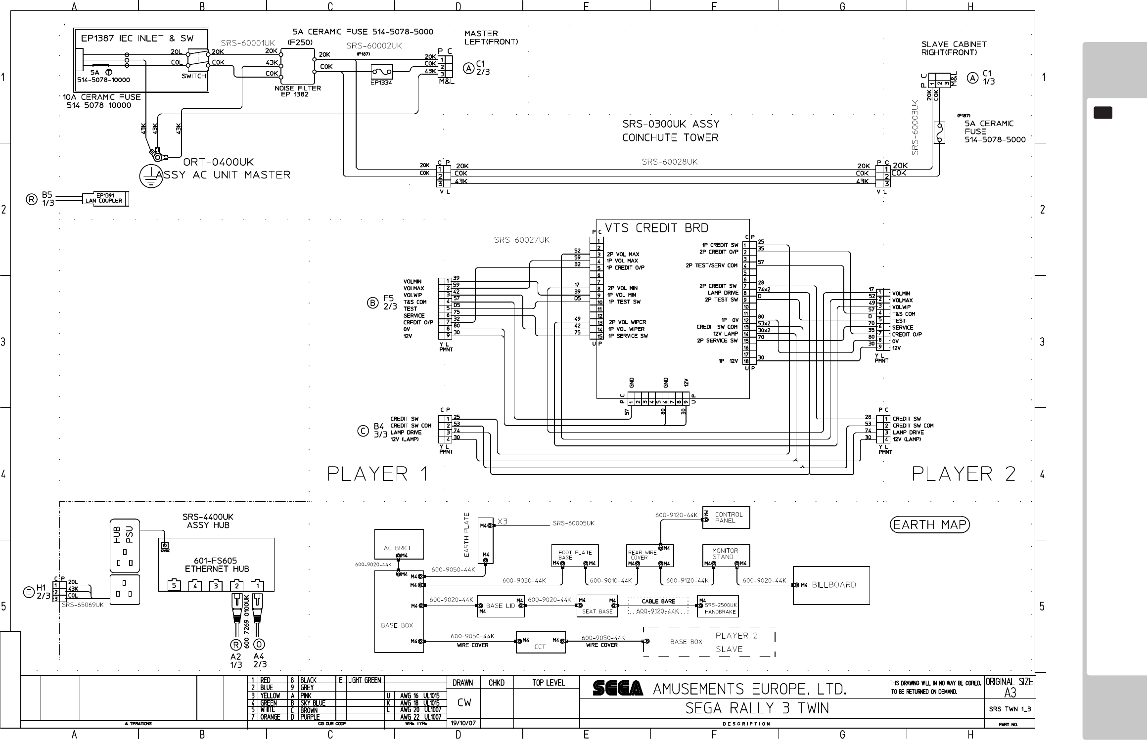
168
WIRINGDIAGRAMS
21
(T-1/34)
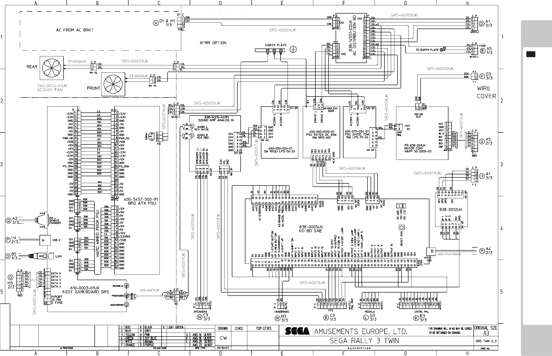
169
WIRINGDIAGRAMS
21
(T-2/3)
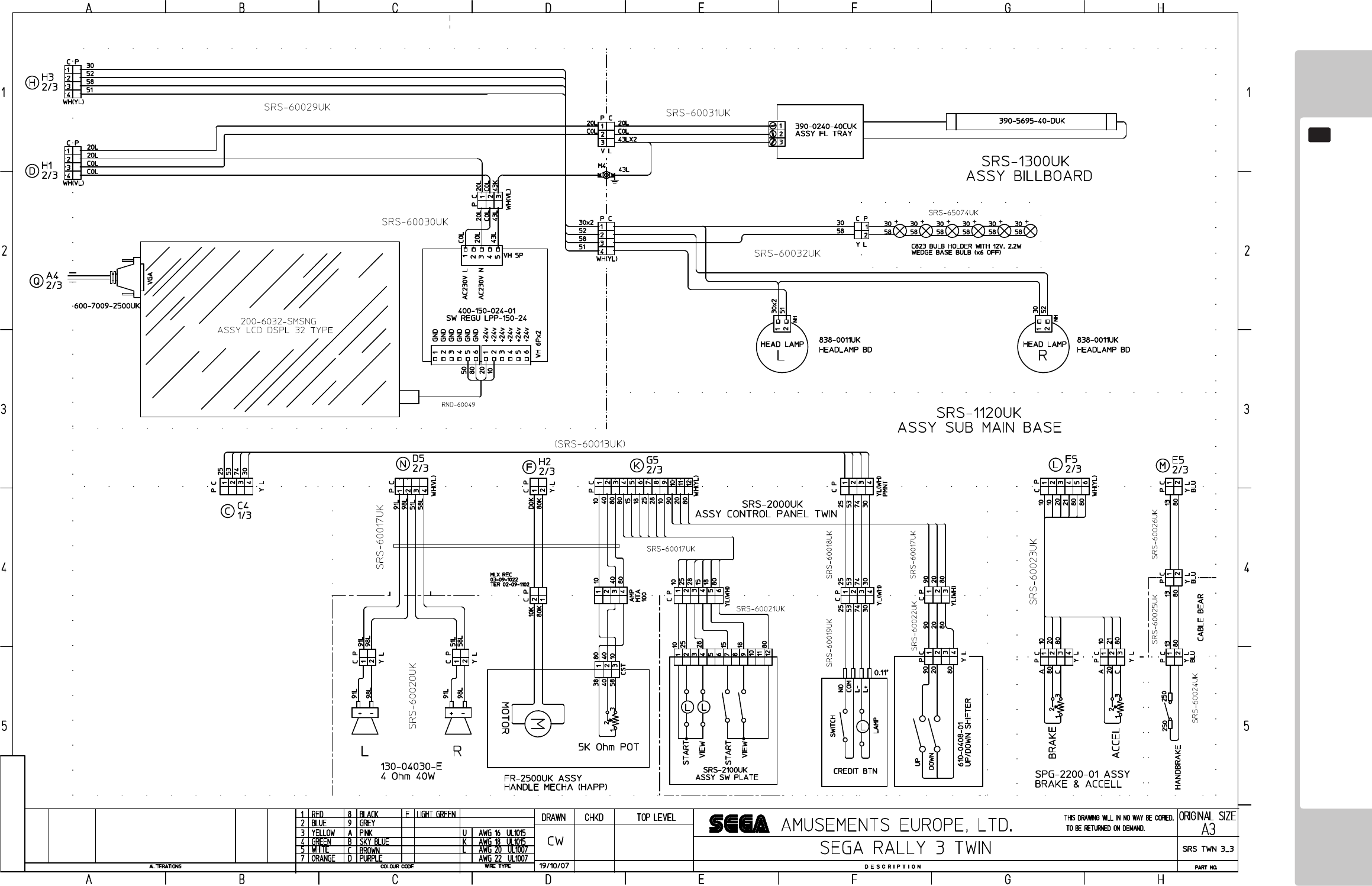
170
WIRINGDIAGRAMS
21
(T-3/3)

-SEGATOTALSOLUTIONS-
42BarwellBusinessPark
LeatherheadRoad,
Chessington,
Surrey,
KT92NY
UnitedKingdom
Tel:+44(0)2083918060
Fax:+44(0)2083918096
ExclusiveSuppliersofSEGASpares
ToHeathrowAirport
