Arcade Slam A Winner Manual Table Of Contents User
2013-11-26
User Manual: Arcade Slam A Winner Manual
Open the PDF directly: View PDF ![]() .
.
Page Count: 13

61-MAN-B
Table of Contents
General Operation……………………………………………………….
How Slam-A-Winner plays
How the Wheel Scores
How the Ball Lift works
3
Programming Options…………………………………………………...
4-6
Troubleshooting Guide…………………………………………………. 7-8
Parts Identification……………………………………………………… 9
Schematics………………………………………………………………
10-13
IMPORTANT: DO NOT USE ABRASIVE CLEANERS ON ANY OF THE
GLASS OR ARTWORK.
2
General Operation
How Slam-A-Winner plays
A player can insert as many tokens as he wishes before he starts dropping balls. Most players
prefer this feature.
A player tries to time a ball drop to go thru a desired hole on the rotating wheel
(see program options for setup).
Note: A player can play as fast as he wants to. He will never lose any ticket values because of 3
or 4 balls on wheel at one time.
Halogen ball lamp turns on when there is 1 or more credits. 10 seconds after the last credit is
used, the ball lamp turns off (in standby the lamp is off).
Note: Replace only with same 20 watt lamp. Do not increase wattage or it may cause
damage to the power supply.
How the wheel scores
A pin is located under the wheel at the home position. When this pin passes through the wheel
opto sensor the home position is identified. Since we know the position of the wheel at all times,
when a ball falls thru a hole that triggers the ball opto sensor, we know the value of that hole and
pay tickets accordingly. Wheel opto sensor and wheel home pin can be viewed from front of
game without opening front door.
Note: There is an opto sensor for the outside row of holes and a sensor for the inside row.
How ball lift works
7 balls are installed at the factory, more than 7 may jam ball lift.
When a ball is dropped, the ball drop switch closes telling the ball lift motor to run until another
ball opens the ball drop switch.
3
Programming Options
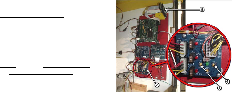
1.) Entering Programming Mode
To enter program mode, press and hold
the left button (SW1)1 located on the
Power Distribution Board2. After 2
seconds, “TOTALS” will appear on the
LCD Display3. At this time, release the
button. “COINS IN” with the number of
coins received will be displayed. The game
is now in Program Mode. PLEASE NOTE
that from this point forward, the left button
(SW1)1 and the right button (SW3)4 on
the Power Distribution Board2 are the
buttons used. These buttons are referred to
on the LCD display as Button 1 and Button
2 respectively. Each programming option is
displayed on the LCD Display, with the functions shown for Button 1 and Button 2.
2.) COINS IN
The total coins received through the coin mechanism are displayed. The total will
rollover to zero when it reaches 1,000,000. Depressing button 2 will display “TICKETS
OUT”.
3.) TICKETS OUT
The total tickets dispensed are displayed. The total will rollover to zero when it reaches
1,000,000. Depressing button 2 will display one of two options:
If there are tickets that have not been dispensed, the Display will show “CLEAR TICKETS
OWED?”, otherwise it will display “ENTER PROGRAM MODE?”
4.) “CLEAR TICKETS OWED?”
This option is displayed if there are tickets that are owed that have not been dispensed,
and will show the number of tickets. Depressing Button 1 will clear these tickets from the
system, and “TICKETS CLEARED” will be displayed. Depressing Button 2 will display
“ENTER PROGRAM MODE?”
5.) “ENTER PROGRAM MODE?”
Depressing Button 1 at this time will enter the area of Program Mode where parameters
may be changed. Depressing Button 2 will return the game to Run Mode.
6.) “ENTER PASSCODE”
To be able to change programming parameters or reset the counters, a 4-digit passcode
must be entered. The default passcode is 0000. To enter the passcode, Depress Button 1 to
change the digit from 0 to 9, then press Button 2 to move to the next digit. After all digits
have been entered correctly, depressing button 2 will Display the first programming option,
“CHANGE PASSCODE?”.
7.) “CHANGE PASSCODE?”
4
Depressing Button 1 will allow for changing the passcode. Depressing Button 2 will
move to “DISPLAY CONTRAST”.
IMPORTANT!!! ONCE THE PASSCODE IS CHANGED, THE DEFAULT OF 0000
WILL NO LONGER WORK! BE SURE TO SAVE THE PASSCODE IN A SAFE
PLACE!
Entering the new passcode is accomplished in the same way that entering the passcode is
done, as explained in 6.) .
8.) DISPLAY CONTRAST
This option sets the contrast for the LCD Display. Depress and hold Button 1 until the
desired contrast is reached, then release Button 1. Depressing Button 2 will move to the next
option, “PLAY MODE VOLUME”.
9.) PLAY MODE VOLUME
This option sets the speaker volume during game play. When this option is entered, the
game’s background music will play continuously. Depressing Button 1 will increase/decrease
the volume. As long as Button 1 is depressed, the volume will increase until the maximum is
reached, then decrease until the volume is off. Depress and hold Button 1 until the desired
volume is reached. Depressing Button 2 will display the next option, “ATTRACTION
MODE VOLUME”.
10.) ATTRACTION MODE VOLUME
This option sets the speaker volume during Attraction Mode. When this option is entered,
the game’s background music will play continuously. Depressing Button 1 will
increase/decrease the volume. As long as Button 1 is depressed, the volume will increase
until the maximum is reached, then decrease until the volume is off. Depress and hold Button
1 until the desired volume is reached. Depressing Button 2 will display the next option,
“ATTRACTION FREQUENCY”.
11.) ATTRACTION FREQUENCY
This option sets the frequency at which the attraction mode occurs. The settings are from
OFF to every 30 minutes. Depressing Button 1 will change the settings in 1-minute
increments from OFF to 30 minutes, then back to OFF. Depressing Button 2 displays the
next option, “COINS PER CREDIT”.
12.) COINS PER CREDIT
This option sets the number of coins required for a credit. The settings are from 1 to 4
coins per credit. Depressing Button 1 will change the setting from 1 to 4, then back to 1.
Depressing Button 2 displays the next option, “BALLS PER CREDIT”
13.) BALLS PER CREDIT
This option sets the number of balls per credit. The settings are from 1 to 3 balls per
credit. Depressing Button 1 will change the setting from 1 to 3, then back to 1. Depressing
Button 2 displays the next option, “JACKPOT INCREMENT”.
14.) JACKPOT INCREMENT
Every time a coin is inserted into the game, the jackpot value is incremented by this
amount. The setting is from an increment of 1 to 10. Depressing Button 1 will change this
setting from 1 to 10, and then revert back to 1. Depressing Button 2 will display the next
option, “SET WHEEL TYPE”.
15.) SET WHEEL TYPE
This option sets the type of wheel being used. Depressing button 1 will select the type of
wheel being used. Depressing Button 2 displays the next option, “SET WHEEL SPEED”.
5

16.) SET WHEEL SPEED
This option sets the speed of the wheel rotation. Depressing button 1 will increase the
wheel speed from 0 to 5 units over the base speed. Depressing Button 2 displays the next
option, setting the “JACKPOT START VALUE”.
17.) JACKPOT START VALUE
This option sets the starting value for the jackpot. This option only appears if the
STANDARD wheel type is selected. Depressing button 1 will increase the start value from
100 to 150 in increments of 5, then back to 100. Depressing Button 2 displays the next
option, resetting the total for COINS IN
18.) RESETTING TOTALS
The totals displayed at the beginning of Program Mode (COINS IN, TICKETS OUT)
may be reset to zero here. The total number for each will be displayed. Depressing Button 1
will clear the total, and zero will be displayed, confirming that the count has been cleared.
Depressing Button 2 will display the next total. Depressing Button 2 after all of the totals
have been displayed will display the next option, “ENTER FREE PLAY MODE?”
19.) “ENTER FREE PLAY MODE?”
If Button 1 is depressed, the game will enter free play mode. This mode is for diagnostic
purposes. In this mode, there is always a credit present on the game, without coins being
inserted.
NOTE: The only way to exit this mode is to turn the power off to the game, or to re-
enter Program Mode and select “NO” for this option. In addition, music plays
continuously in this mode.
When this option is displayed, depressing Button 2 will display the next option, “ENTER
PROGRAM MODE?”
20.) “ENTER PROGRAM MODE?”
This option gives the opportunity to re-enter program mode if it is necessary to change
any options again. Depressing Button 2 leaves Program Mode and the game returns to
normal, Run Mode.
DEFAULT SETTINGS
PASSCODE 0000
PLAY MODE VOLUME 42
ATTRACTION MODE VOLUME 42
ATTRACTION FREQUENCY 5 Minutes
COINS PER CREDIT 1 Coin
BALLS PER CREDIT 1 Ball
JACKPOT INCREMENT 1 point
WHEEL TYPE STANDARD
WHEEL SPEED +0
JACKPOT START VALUE 125(1)
(1) The Jackpot Start Value programming option is enabled for
the STANDARD wheel only.
6
Troubleshooting Guide
Problem What to Check
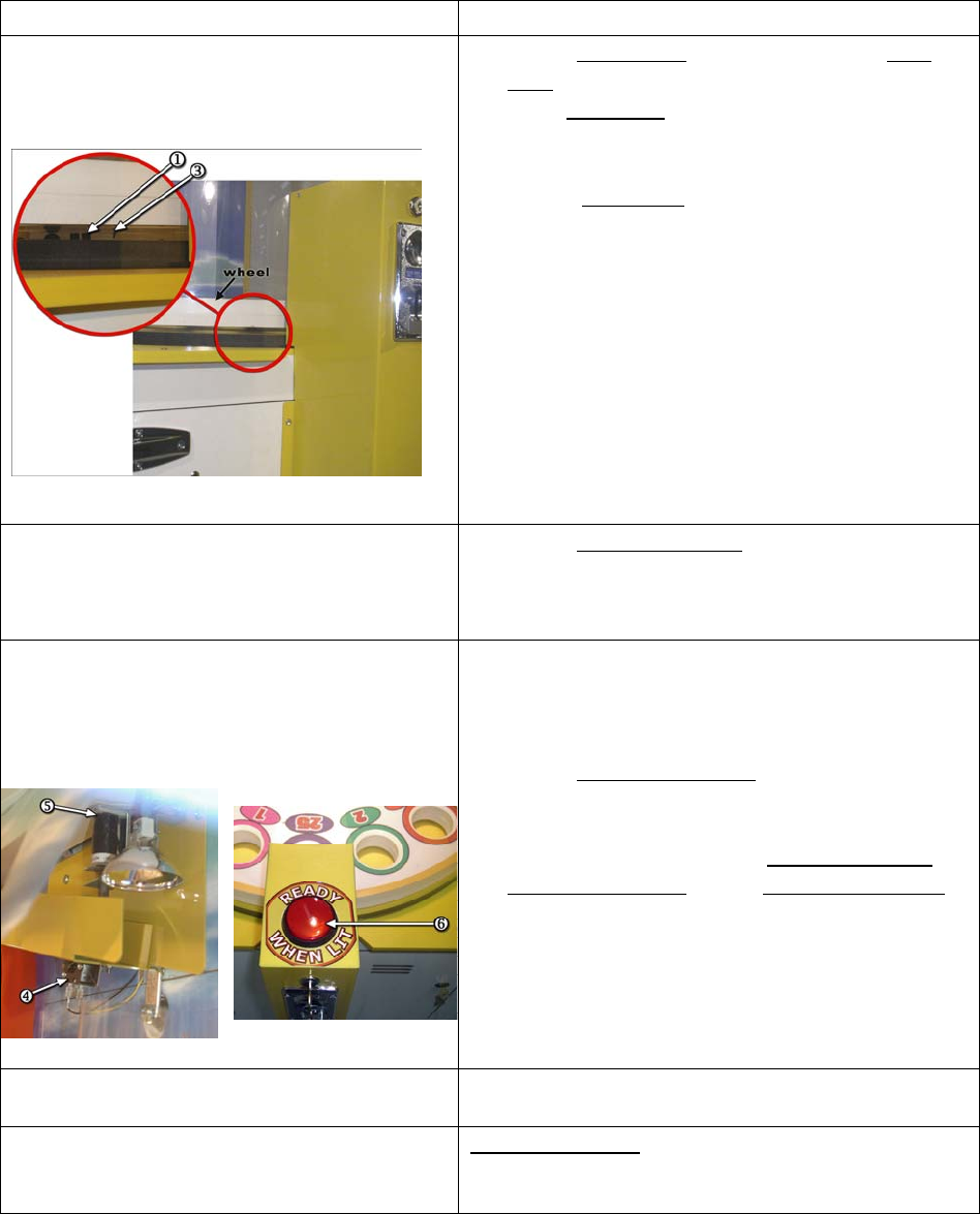
Wheel runs briefly, stops, and restarts
over and over again
1. Check wheel opto1 operation; wheel opto
light2 should flash once per wheel revolution
when wheel pin3 (pressed into the bottom of
the wheel) passes through opto. If light does
not flash:
• Wheel pin3 may not be low enough
to break opto beam
• Power may not be connected to wheel
opto pcb
2. Check opto output; opto should transition
from +5V to 0V when opto beam is broken.
If opto pcb has power but there is not
transition on the output, the opto pcb is bad.
If signal transitions all the way back to the
Controller board, controller board may be
bad.
3. Check motor adjustment.
Ball does not drop when ball drop
button is pressed and ball drop button
does not illuminate when credits are
available
1. Check ball ramp switch4 adjustment
2. Make sure the output wire is connected to the
NC (normally closed) side of the ball ramp
switch.
Ball does not drop when ball drop ball
button is pressed and ball drop button
does illuminate when credits are
available
1. Check for out of round or oversized balls.
Check ball size by inserting them into the
Jackpot hole in the wheel. They should pass
through the holes without interference.
2. Check ball drop solenoid5 (if solenoid does
not move at all, it is most likely the ball ramp
switch)
3. Check wire connection to ball ramp switch4,
ball drop solenoid5, and ball release button6
Ball Lift Jams Too many balls in machine. There should be 7
balls loaded in the machine.
Ball lift runs forward, then backward,
then forward again over and over and/or
Balls build up on ball ramp
Ball ramp switch4 is out of adjustment or not
working. Switch output should be connected to
NC terminal.
7
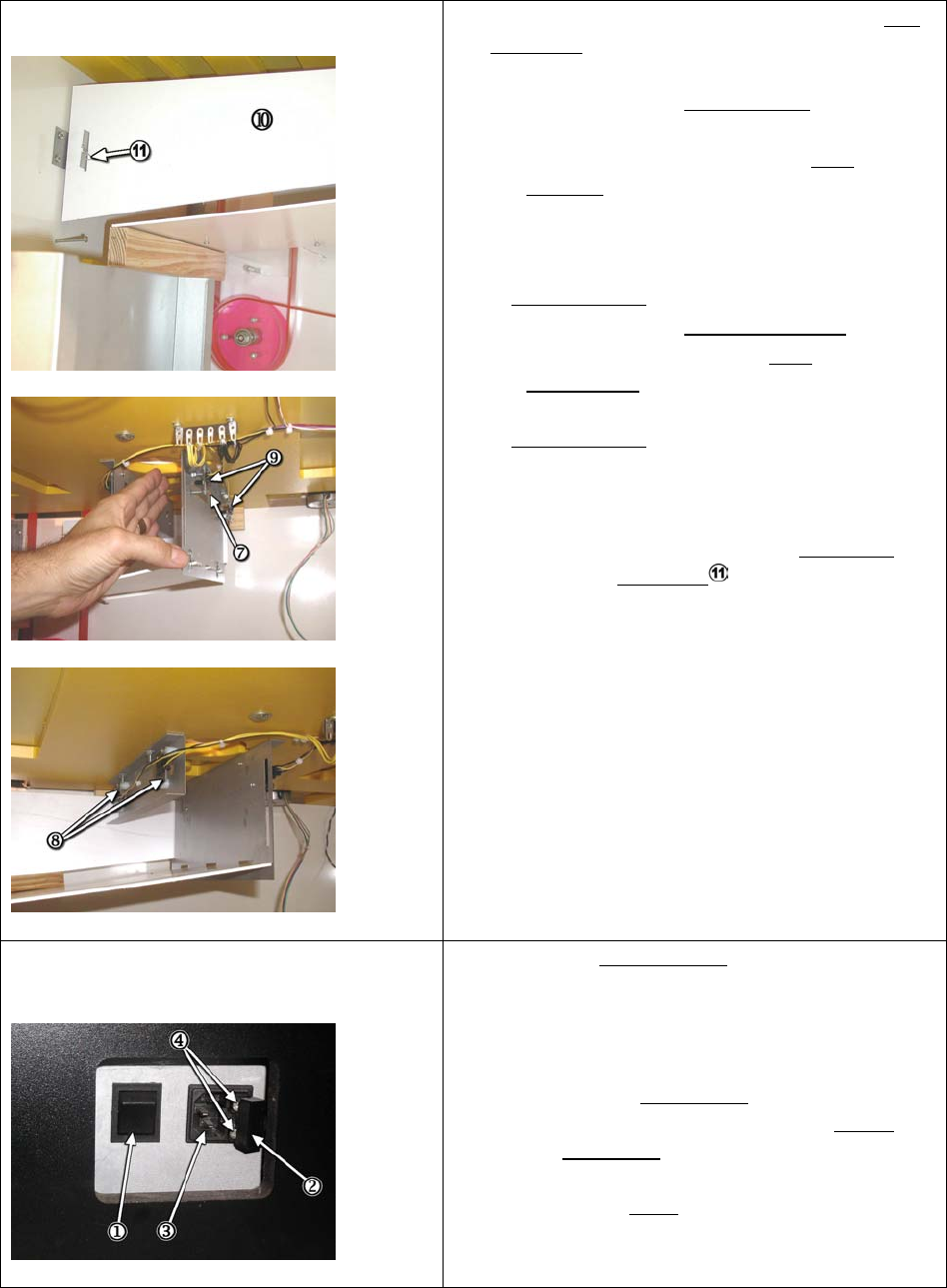
Balls do not score
1. Check ball sensing opto sensors to see if ball
opto light7 goes on when opto beam is
blocked. If light does not go on:
• Check power to opto receiver9 sensor
pcb’s
• Check output signal from the opto
receiver9 pcb. Output from opto receiver
should transition from +5V to 0V when
opto beam is blocked. If not, the opto
receiver should be replaced.
2. If ball opto light7 is always on:
• Check power to opto transmitters8
• Check to be sure that the opto
transmitters8 and receivers are in
alignment.
3. If ball opto light7 does go on and the output
transition from the opto receiver pcb is
detected all the way to the controller board,
then the controller board is bad.
Note: You will need to remove the ball cover
by removing the cotter pin to access transmitter
side of opto sensors and to block opto path for
testing.
Game does not power on
1. Check that power switch1 is in the “ON”
position
2. Check that power cord is good
3. Check power input fuses:
a. With a small flat head screwdriver,
pull the fuse holder2 out. Fuse
holder is located next to the power
input plug3.
b. Tilt the fuse holder cover to the side to
access fuses4
c. Replace fuses (5 Amp) if necessary
and push fuse holder back into place.
8
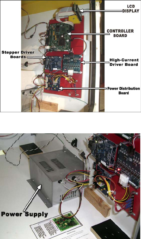
Parts Identification
9
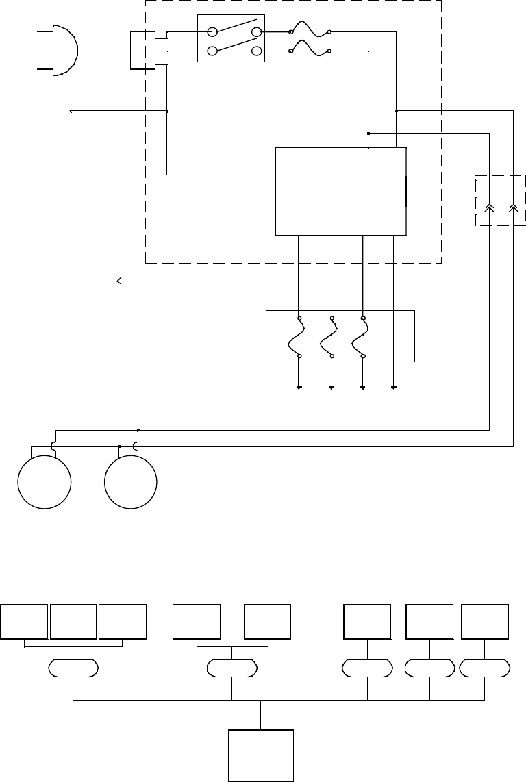
standby amp. 1.5
110 WATT POWER SUPPLY
power
distribution
pcb.
from 90 to 240 50/60 hz ac
volts input
slam-a-winner
wheel motor
ball lift
motor
ticket
dispenser
coin
chute
C- is smybol for connector
com puter chassi c
power supply
max. amp. 2
ball opto
transmitter
opto
wheel
home
drop bal l
swit ch
assy .
C-2 (8 pin)C-1 (6 pin)
ball opto
receiver
ac power schematic 90 volts to 240 volts
slam-a-winner connector location
C-3 (4 pin) C-4 (4 pin) C-5 (4 pin)
5 amp5 amp
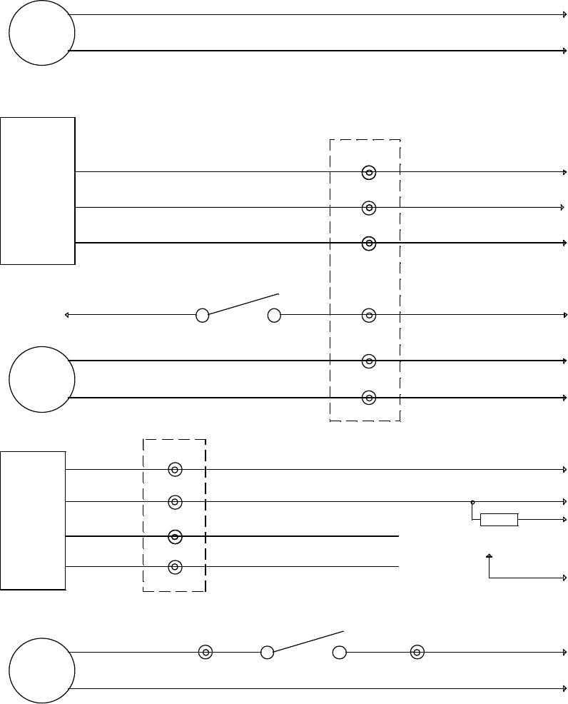
COMPUTER
PO W E R CO RD
GRE EN/YELL OW
16 G A.
12 volt
+
5 volt +12 volt
+
5 AMP. FUSE
5 AMP. FUSE
12 volt
+
5 volt + ground
90/ 240 ac
50/60 hz
EARTH GROUND CONNECTS TO ALL
BON DED METAL PAR TS
ON/OFF SWITCH d.p.s .t
BL ACK - WHITE
TWISTED PAIR
BL ACK - WHIT E
TWISTED PAIR
CABINET
LA MP 23
WATT
24 volt
+
WHITE
BLACK
12 volt
+
5 volt + ground
POWE R INP UT BOX
CABINET
LA MP 90 wa tt
ha lo ge n
5 amp
10
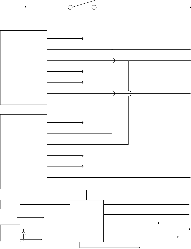
drop ball switch
white
black
red
drop switch
lamp yellow
slam-a-winner
front door
black orange black orange
C-3
white-black
yellow
low ticket
lamp
blue
yellow
black
C-3
blue
C-2
black
ground
ticket
dispenser
ground
notch
run
C-3
C-3
12 volt (+)
5 v (+)
cpu j1-4
ground
12 volt (+)
C-2
white
12 volt (+)
white-black
red-black
cpu j1-1
cpu j2-9
cpu j3-7
yellow
cpu-j2-19
ground
12 volt (+)
yellow
black
C-2
C-6 pin 1
ticket level switch
C-6 pin 2
black
cpu j3-11
10 k
green
C-2
enable
cpu j3-15
green
coin
comparator
C-2
12 volt (+) red yellow
C-2
output
12v fuse f-a
j2-4
high current pcb
pink-white
pink-white cpu-j3-18
ground
blackblack
SPEAKER
11
to coin mech
enable
black orange
ground
blue black
5 volt (+)
j2-2 j1-4
j1-10 j2-4
brown-white cpu j 2-4
12 volt (+)
high current driver
j2-10
j1-3 cpu j 2-8
yellow
balldrop
solenoid
j1-5j2-1 j2-5
grey- yellowhalagon
lamp
violet-white
12 volt (+)
white-green cpu j2-15
credit display 2 digit
ground
cpu j2-11
ball ready switch n.c.
jackpot display 3 digit
12 volt (+)
yellow
12 volt (+)
red
black
blue-yellow
green-white
latch 3
ground black yellow-green cpu j 3-2
blue-yellow
red
black
yellow
data 6
5
1
2
4
green-white
grey-red
cpu j2-20
cpu j2-21
5 volt dc
clock
latch 3
5
data 6
12 volt (+)
clock
5 volt dc
2
slam-a-winner
4ground
yellow
1
white-brown cpu j 2-10
12
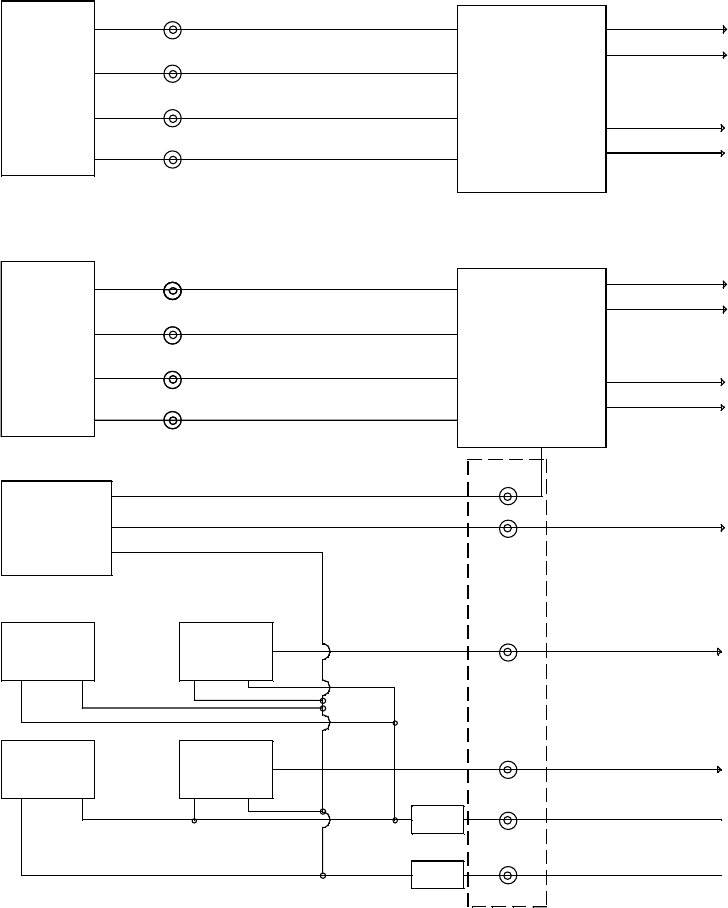
outer ring opto
receiver
13
2
31
inter ring opto
transmitter
outer ring opto
transmitter
1331
2
5 volt dc
C-1 pin 1
C-1 pin 4
t/s
t/s
black
yel low 12 volt (+)
ground
yellow
black
C-1 pin 6
C-1 pin 5
C-1 pin 2
C-1 pin 3
blue-orange
black
yellow
cpu 485 comm.1
violet
2
1
2
1
j1-3
j1-4
cpu 485 comm.2
grey
violet cpu 485 comm.1
grey cpu 485 comm.2
violet-yellow cpu j3-10
ball lift motor 30
ohm econo stepper pcb
econo stepper pcb
orange
black ground
24 volt dc
j1-4
j1-3
pink
blue
phase 1 pink
24 volt dc
ground
black
orange
j1-13
cpu j3-1
white-violet
red-white
wheel motor 30
ohm
phase 1
pink
C-7 pin 3
C-7 pin 4
j1-8
blue-white
phase 1phase 1
green
pink
yel
phase 1
phase 1
phase 2
phase 2
phase 2 white-blue
C-4 pin 1
j1-2
j1-9
j1-1
j1-8
brown-yellow
red
black
pink
yel low-whi te
red-white
yel low-white
C-4 pin 4
C-4 pin 3
C-7 pin 1
C-7 pin 2
wheel homeopto
white-orange
yelyel yel low-red
phase 2 green
blue
phase 2
phase 2
receiver
C-4-pin 2
j1-2
j1-9
j1-1
slam-a-winner
inter ring opto
13
