Arcade Sonic Sport Basketball Manual 20090810Sonic_Sport_Basketball User
Sonic Sport Basketball Manual Sonic Sport Basketball Manual Sonic Sport Basketball Manual files sharedfiles soe-web-arcade2-pub
2013-09-30
User Manual: Arcade Sonic Sport Basketball Manual
Open the PDF directly: View PDF ![]() .
.
Page Count: 48
20090810 街頭籃球(尚瑩 SEGA 版)(CXX_ACXX0V)英文版

- 2 -
Table of Contents
Special note..................................................................................................................... 3
Maintenance and Inspection ........................................................................................... 3
I.Inspection...................................................................................................................... 3
1.Parts list .................................................................................................................. 4
2.Half-Assembly type parts list................................................................................... 5
II.Machine view/size and power rating............................................................................. 6
III.Component description ............................................................................................... 6
IV.Assembly and disassembly ......................................................................................... 7
1. Assembly and disassembly for Assembly type....................................................... 7
2. Assembly and disassembly for Half-Assembly type ............................................. 19
3.【SET-UP Position & maintenance】................................................................... 28
V.Adjustment and Inspection ......................................................................................... 28
1.Link adjustment..................................................................................................... 29
【Cable link SET-UP】............................................................................................ 29
【Link main board adjustment】.............................................................................. 30
2.Adjustment............................................................................................................ 31
【SET-UP 1】SET-UP the coin entry price for each game ................................ 31
【SET-UP 2】Additional tickets ......................................................................... 32
【SET-UP 3】Multiple of tickets......................................................................... 32
【SET-UP 4】Game Time SET-UP ................................................................... 33
【SET-UP 5】Basket motor AUTO test ............................................................. 34
【SET-UP 6】Ball holder motor AUTO test ....................................................... 34
【SET-UP 7】Reset the top score 250 or keep the record ................................ 34
【SET-UP 8】SET-UP DEMO music(ON or OFF)........................................ 34
3.LED Monitor inspection......................................................................................... 35
- 3 -
4.Bookkeep.............................................................................................................. 35
5.Error code ............................................................................................................. 36
VI.How to play ............................................................................................................... 37
1.There are total 4 Stages ....................................................................................... 37
2.2 play types available............................................................................................ 38
VII.Screw and Nut list .................................................................................................... 38
VII.Expended view......................................................................................................... 40
Special note
We want to thank you for choosing our Street basketball machine,
and hope you read these instructions first to insure the security
of the user before this product is used.
This Manual contains the characteristics, special notes, and a
Simple breakdown of the product.
Maintenance and Inspection
■ Keep the machine clean by using mild types of cleaners.
■ Clean the machine regularly to maintain its appearance.
■ The appliance must not be cleaned by a water jet.
■ Treat acrylic with care by using Windex
I.Inspection
Before product use, please confirm the product content first, if anything is
missing, please contact us right away.
Machine position regulation
The power must be turned off before any movement.
The brake must be released, before the machine is moved.
Do not put the machine under the direct sunlight, it will damage the inside parts.
- 4 -
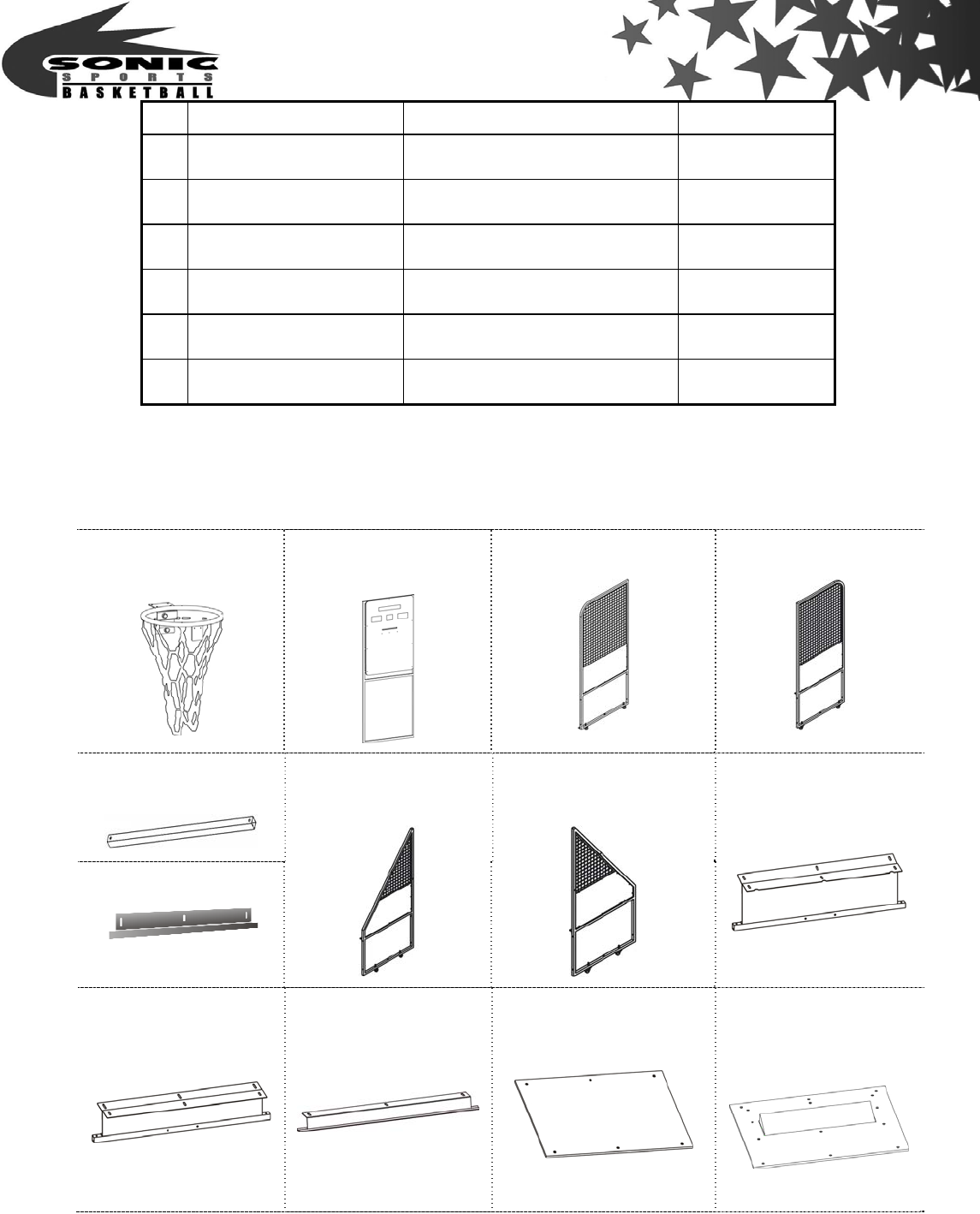
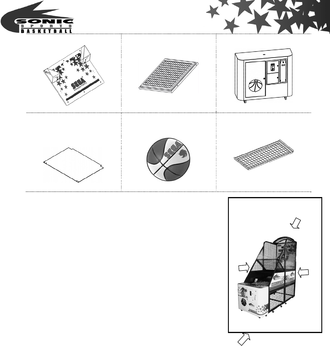
NO Items Specification Total quantity
1 Chassis items Packing 1 unit
2 Street basketball No.5 Basketball 10 unit
3 Key Maintenance door 1 pc
4 key Cash box 1 pc
5 AC cable line 1 unit
6 Operation manual A4 1 set
1.Parts list
1B Basket kits
2A Basket board
2BR Back right net
stander kit
2BL Back left net
stander kit
2C 2 Front net
stander bridge(short)
4D Base holder BB
3A Front right net
stander kit
3B Front left net stander
kit
4A Base holder BF
4B Base holder FB
4C Base holder FF
5A Wooden base
A type
5B Ball holder kit
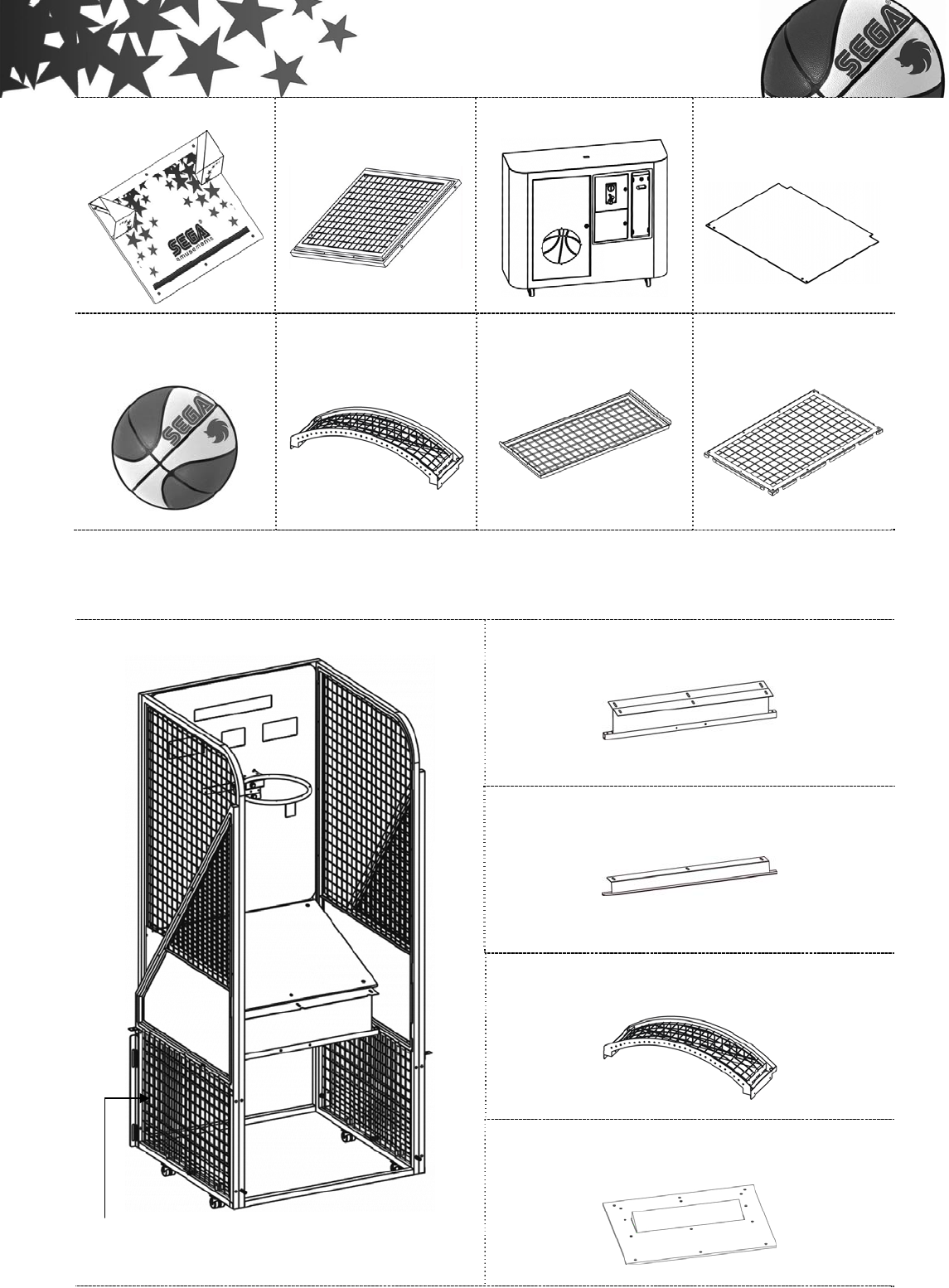
- 5 -
5C Ball guide kits
6A Ball net holder kit
6B Main part
6C Block wooden
board for motor
Basketball
Top cover(optional)
Metal Shelf (optional)
Lower Side Net
(Frame Included)×4
(optional)
2.Half-Assembly type parts list
4B Base holder FB
4C Base holder FF
Top cover(optional)
Main frame
5B Ball holder kit
Lower Side Net
(Frame Included)×4 (optional)
- 6 -
5C Ball guide kits
6A Ball net holder kit
6B Main part
6C Block wooden board
for motor
Basketball
Metal Shelf (optional)
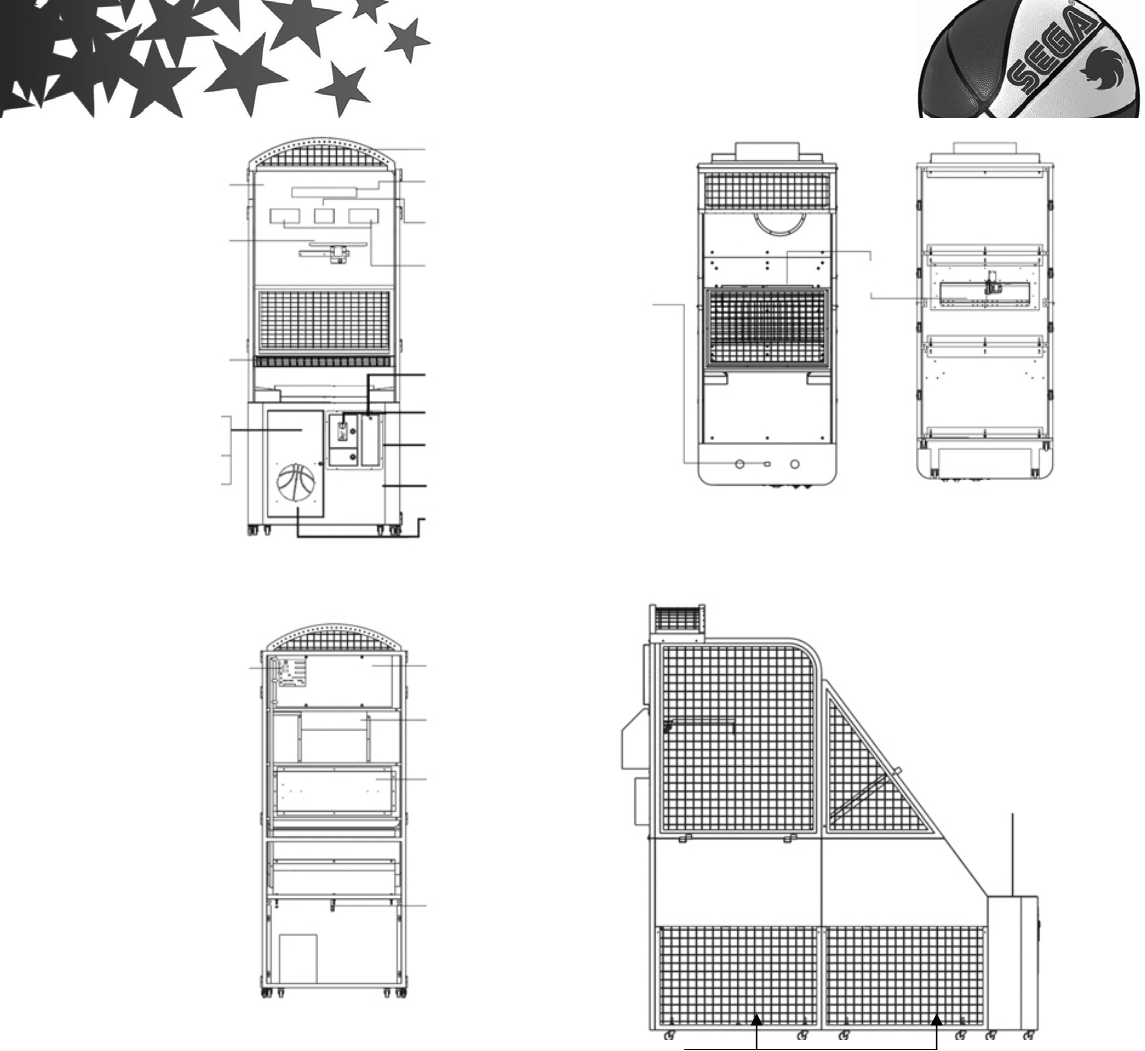
II.Machine view/size and power rating
Machine Dimensions:W1030×D2500×Top cover H2643mm
Weight:260 kg / 558.4 lbs (Accessories not Included )
(Top cover 6.6kg、Metal Shelf 3.4kg、Lower Side Net 4.2kg×4)
Voltage:AC110V~120V/AC220V~240V(50/60Hz) Use Electrical
plug display as a glide Located behind the machine.
Power Consumption:200W
Fuse:2A(AC220V~240V)/ 5A(AC110V~120V)
Token size:φ22mm~27mm
III.Component description
【Front】 【Base】 【Top】
Position direction
L
e
ft
Right
Back
Front
- 7 -
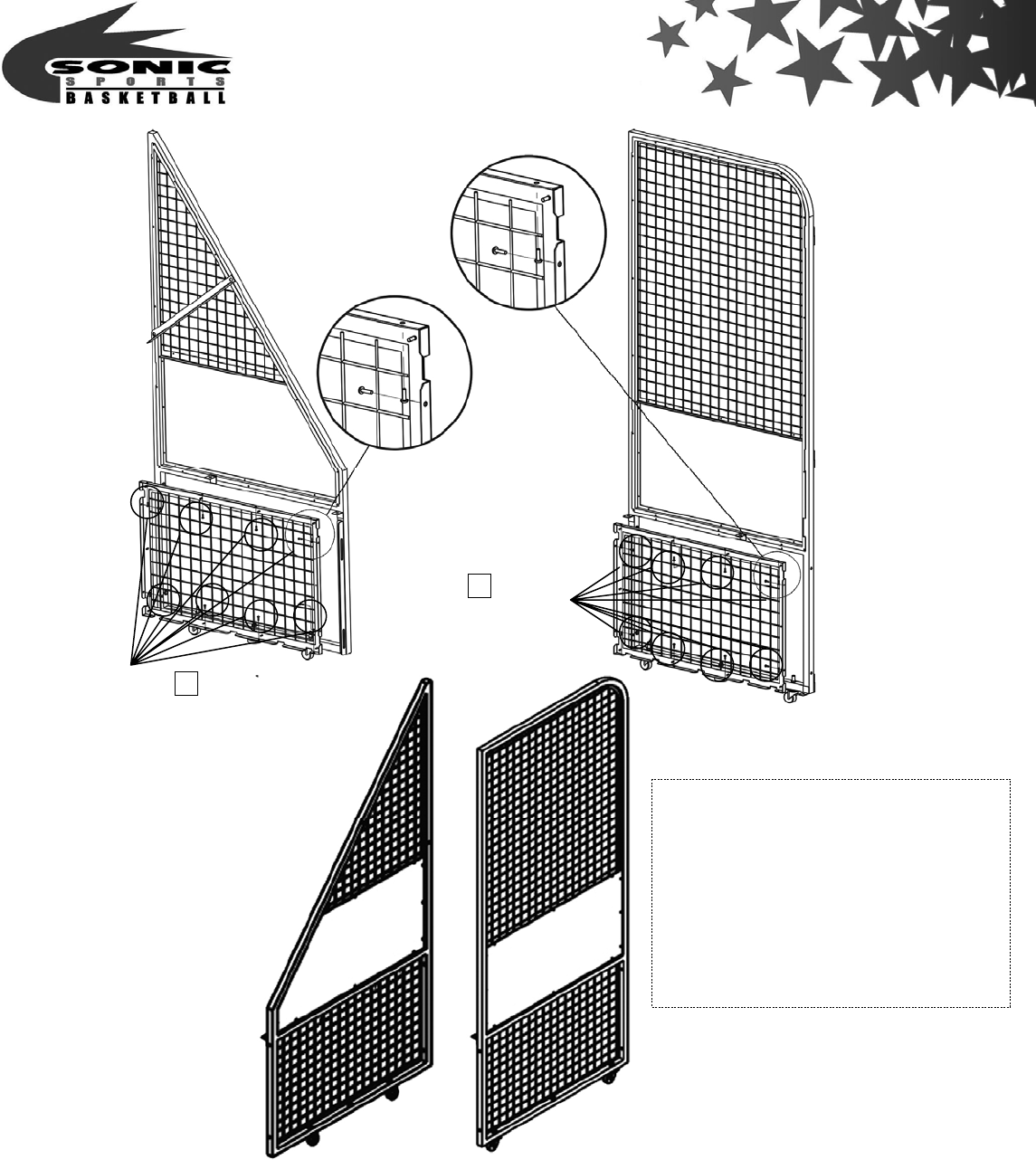
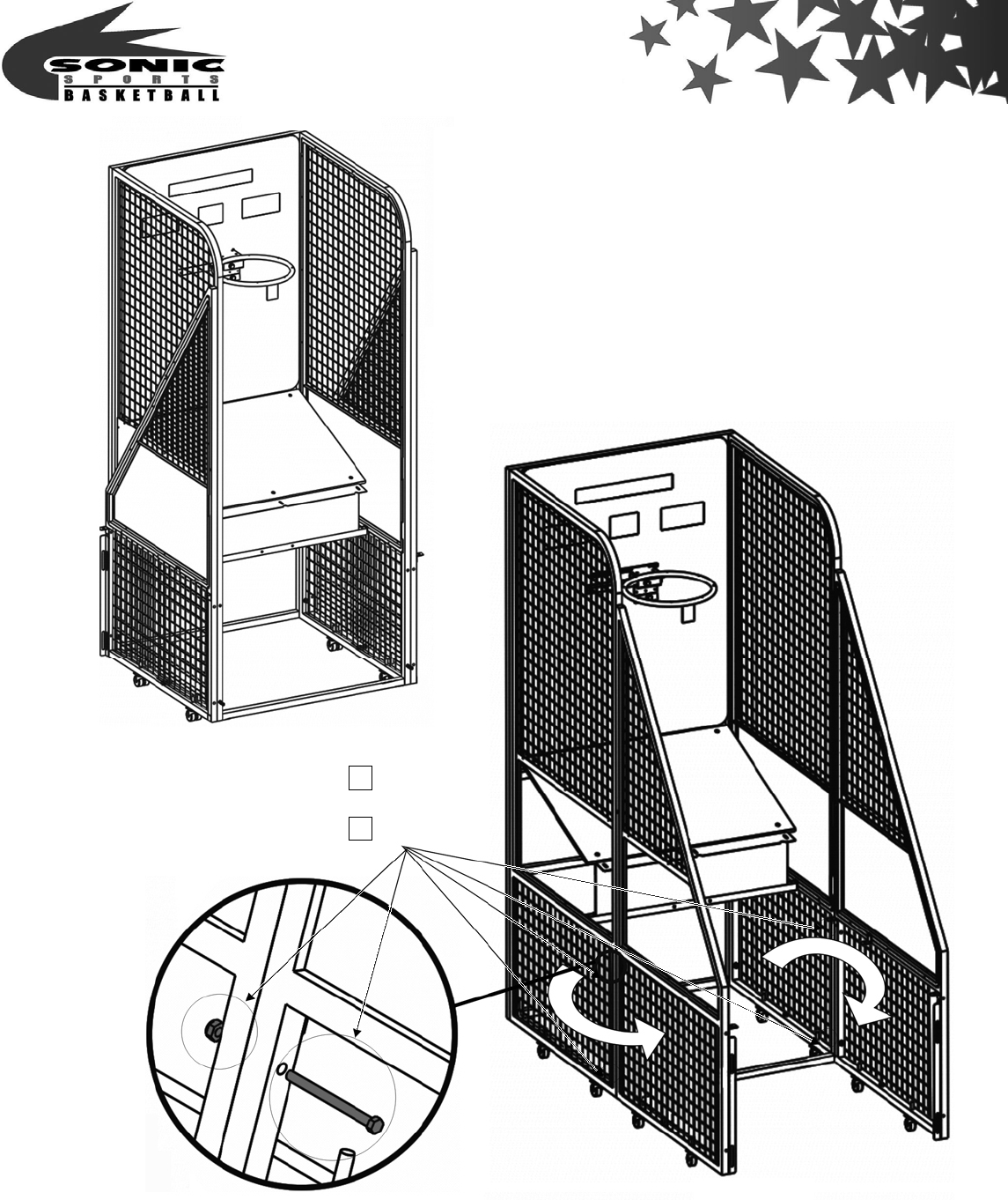
IV.Assembly and disassembly
1. Assembly and disassembly for Disassembly type
Step 1:
1.Screw【Lower Side Net (optional)】on the basket board front.
【Back】 【Side】
To
p
cover
(
o
p
tional
)
Light board display
LED display(2 figures)
LED display(3 figures)
Coin LED display
(2 figures)
Ticket dispenser
Coin selector
Ticket box
(
inside
)
Cash box
(
inside
)
Bass speaker
Basket board
Basket kit
Metal Shelf
(
o
p
tional
)
IC Board
Power、
Tes t
Book
keep
Fuse
Ball
holder kit
Board cover
Basket cover
Light cover
AC Cable line
Electrical plug display
I/O control Board
Main
p
art
Lower Side Net
(Frame Included)×4(optional)
- 8 -
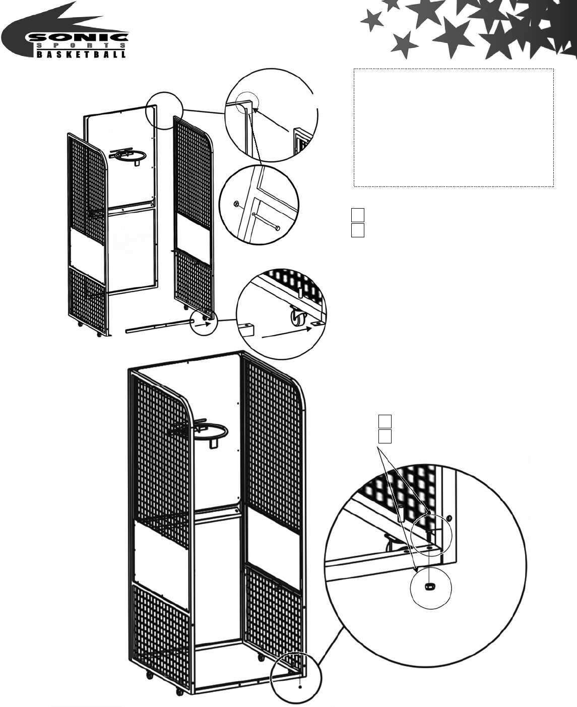
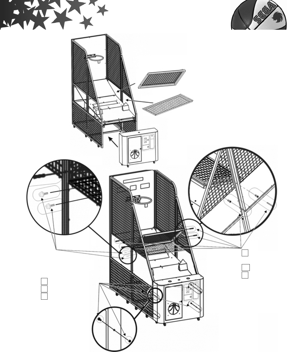
Step 2:
1.Screw【1B Basket kits】on the basket board front.
Assembly parts
2BR Back right net stander kit
2BL Back left net stander kit
3A Front right net stander kit
3B Front left net stander kit
Lower Side Net(Frame Included)
P.35 NO.32
screw(M4×10)×10
P.35 NO.32
screw(M4×10)×10
- 9 -
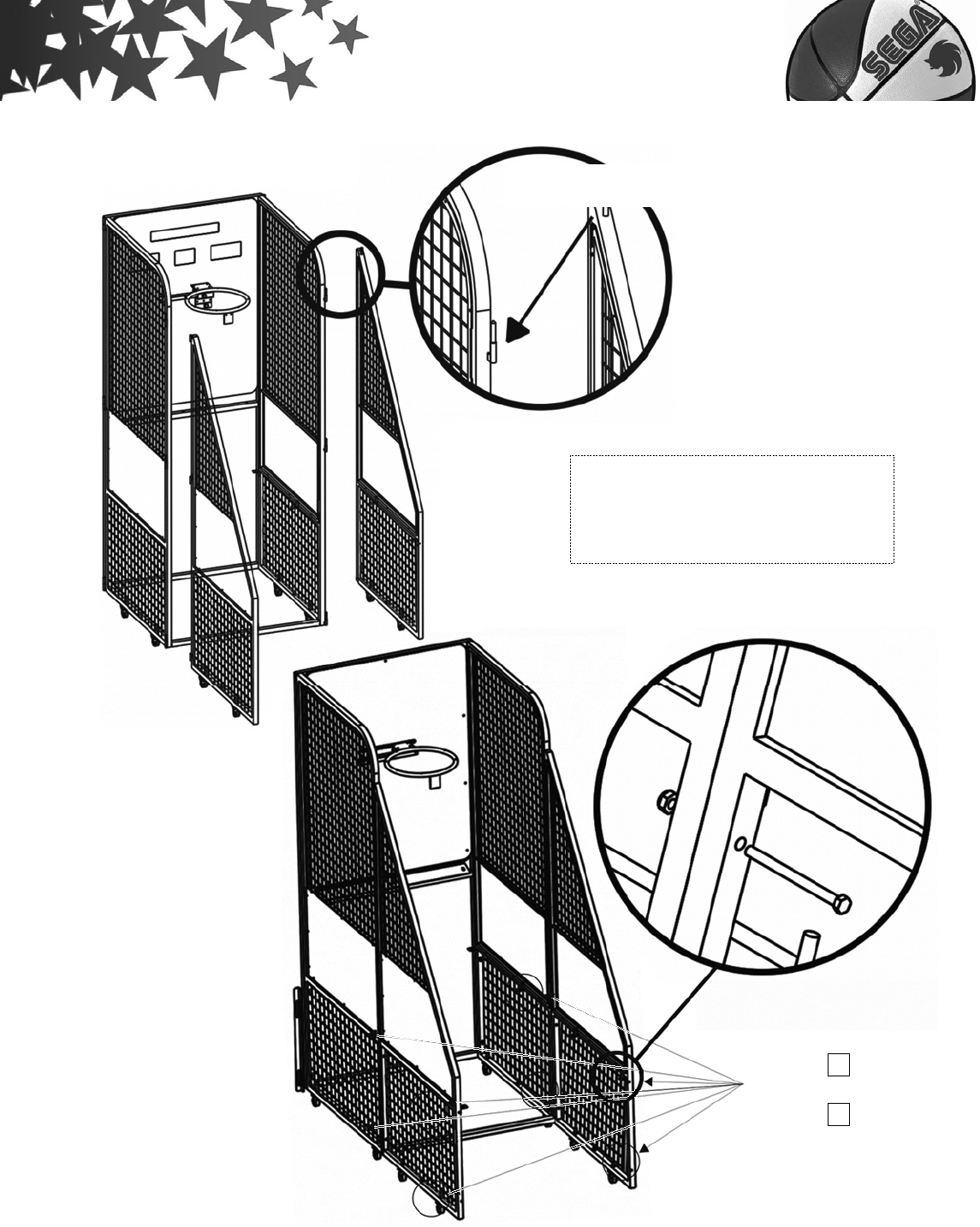
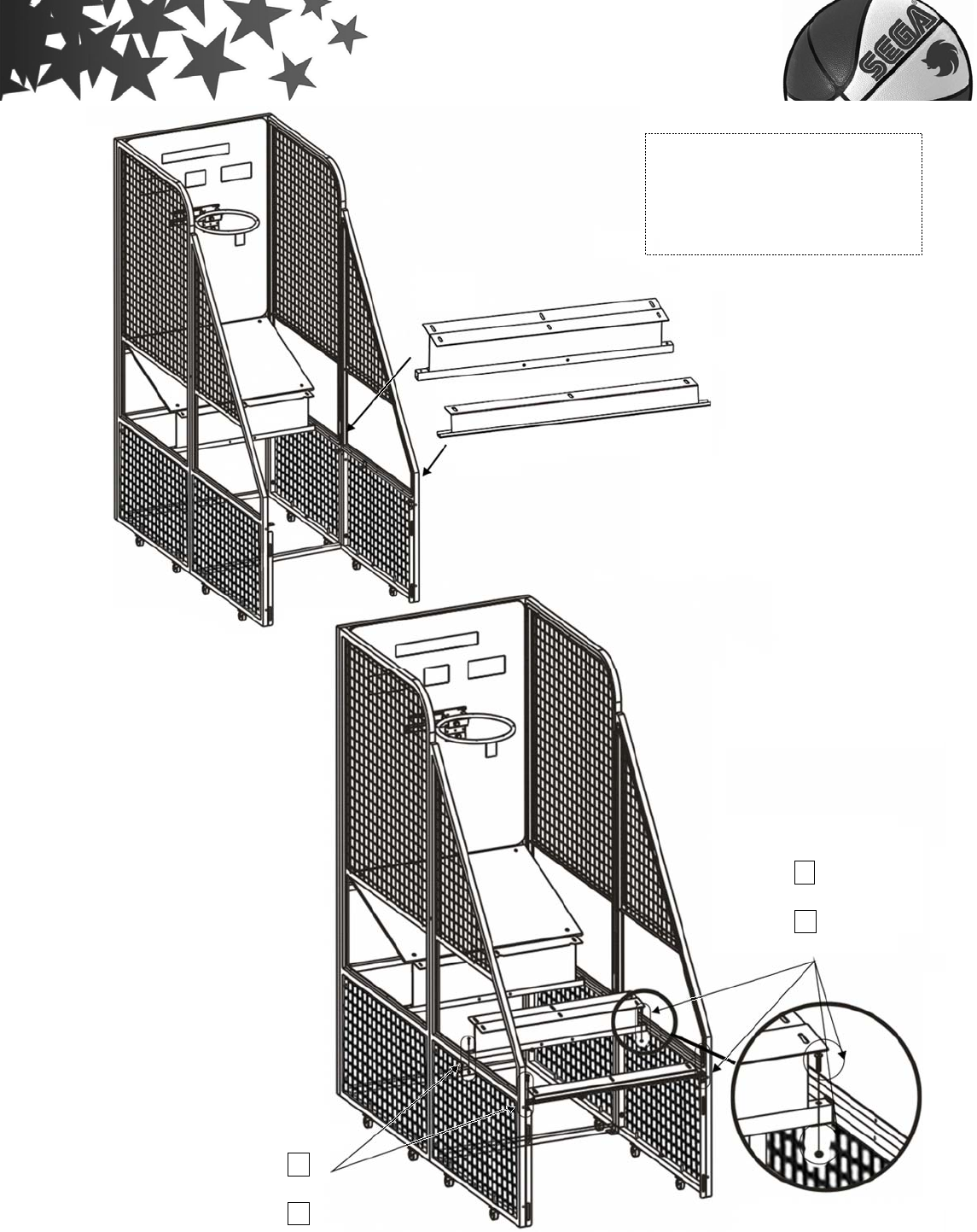
Step 3:
1. Screw【2BR、2BL Back left & right net stander kits】on basket board left and right.
2. Screw【2C Front net stander bridge(short)】on Back left & Right net stander kits.
P.34 NO.13 screw(M6×18)×2
screw(M6×16)×2
P.35 NO.21 nut(M6)×4
Assembly parts
1B Basket kits
2A Basket board
- 10 -
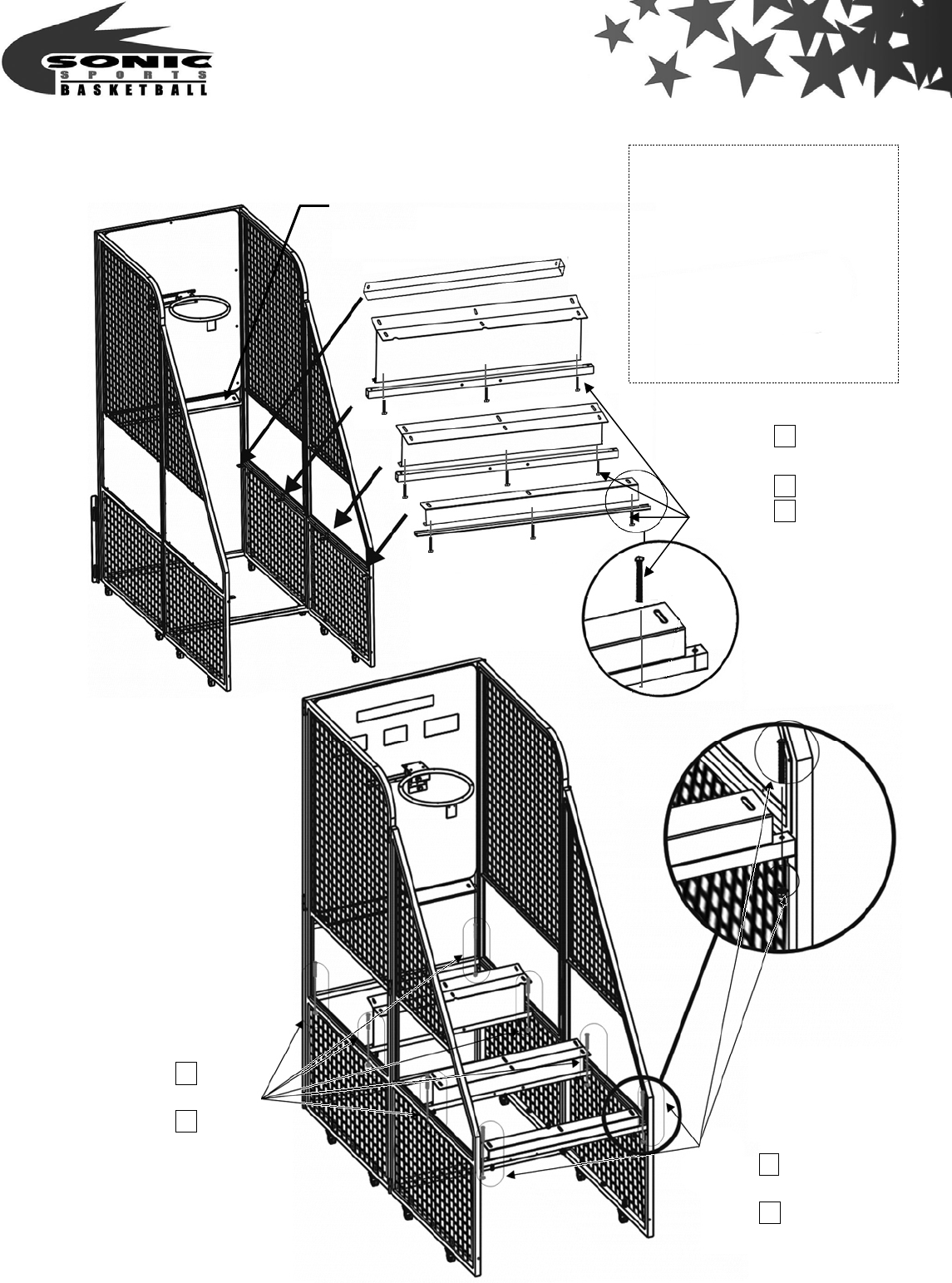
Step 4:
Assemble【3A、3B Front right & left net stander kit】on basket board left and right,
Assembly parts
2A Basket board
2BR Back right net stander kit
2BL Back left net stander kit
2C Front net stander
bridge(short)
P.34 NO.10 screw (M6×48)×2
P.35 NO.20 nut (M6)×2
Insert position
P.34 NO.04 screw (M8×88)×4
P.35 NO.19 nut (M8)×4
- 11 -
connect with screw & fixed it as drawing.
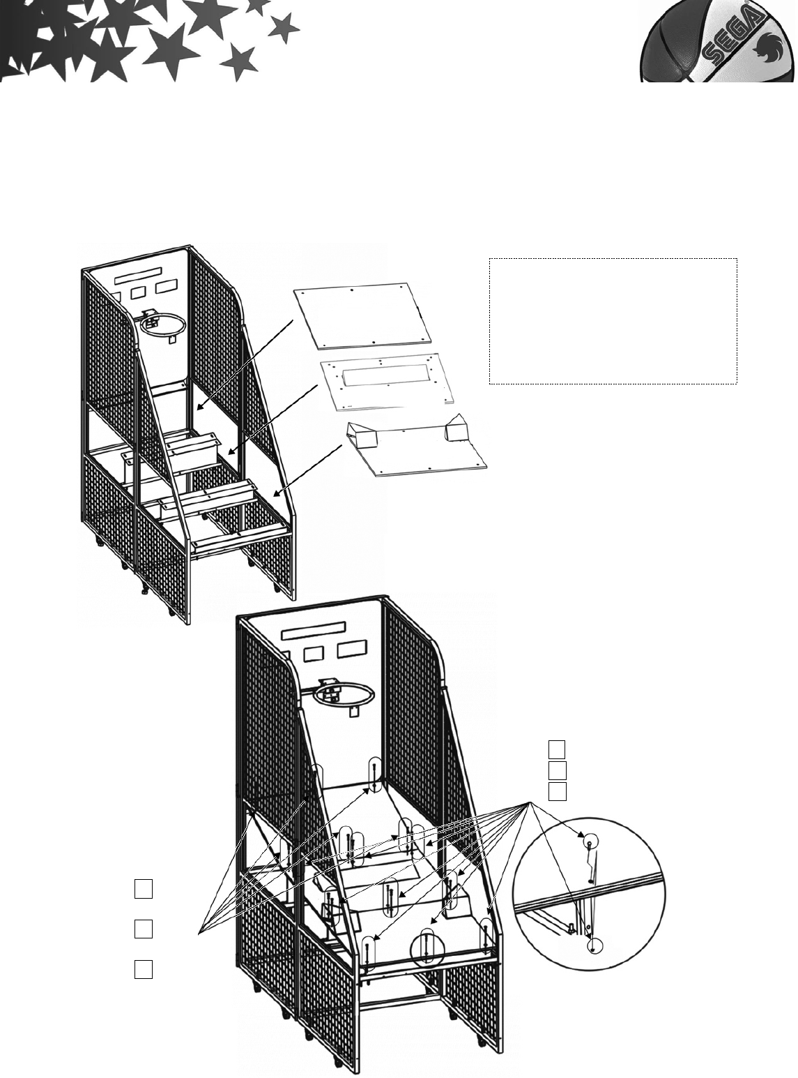
Step 5:
Assembly parts
3A Front right net stander kit
3B Front left net stander kit
Insert position
P.34 NO.04
screw (M8×88)×4
P.35 NO.19 nut (M8)×4
- 12 -
Screw the【BF、FB、FF Base holders & Front net stander bridge(short)】step by
step as drawing.
Assembly parts
2C Front net stander
bridge(short)
4A Base holder BF
4B Base holder FB
4C Base holder FF
4D Base holder BB
Front net stander bridge(short)
BF
FB
FF
P.34 NO.11
screw (M6×26)×2
P.35 NO.20 nut (M6)×2
P.34 NO.10
screw (M6×48)×6
P.35 NO.20
nut (M6)×6
Base holder BB
P.34 NO.10
screw (M6×48)×9
P.35 NO.20 nut (M6)×9
P.35 NO.30
washer(M6.5×13.5)×9
- 13 -
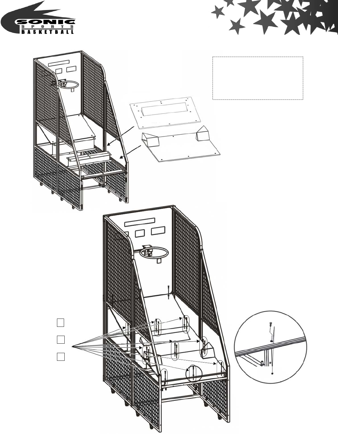
Step 6:
Screw the【5A Wooden base A type、5B Ball holder kit、5C Ball guide kits】step by step
as drawing.
Assembly parts
5A Wooden base A type
5B Ball holder kit
5C Ball guide kits
Wooden base A type
Ball holder kit
Ball guide kits
P.34 NO.11 screw (M6×26)×12
P.35 NO.20 nut (M6)×12
P.35 NO.30 washer(M6.5×13.5) ×12
P.34 NO.10
screw (M6×26) ×6
P.35 NO.20
nut(M6) ×6
P.35 NO.30
washer(M6.5×13.5) ×6

- 14 -
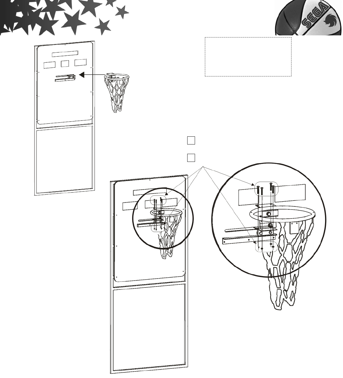
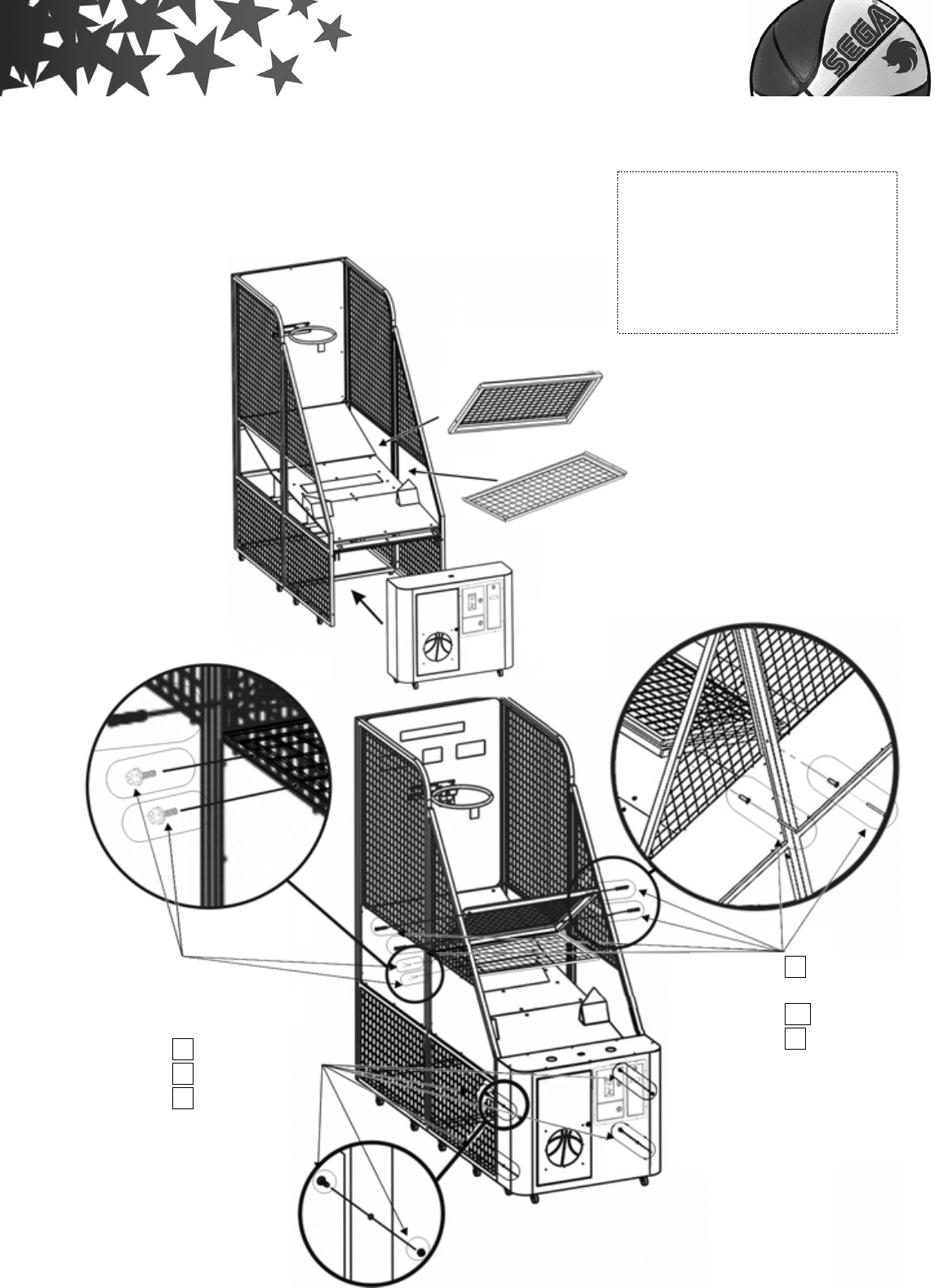
Step 7:
1. Screw【6A Ball net holder kit】.
2. Screw【6B Main part】、【Metal Shelf (optional)】.
Assembly parts:
6A Ball net holder kit
6B Main part
Metal Shelf (optional)
- 15 -
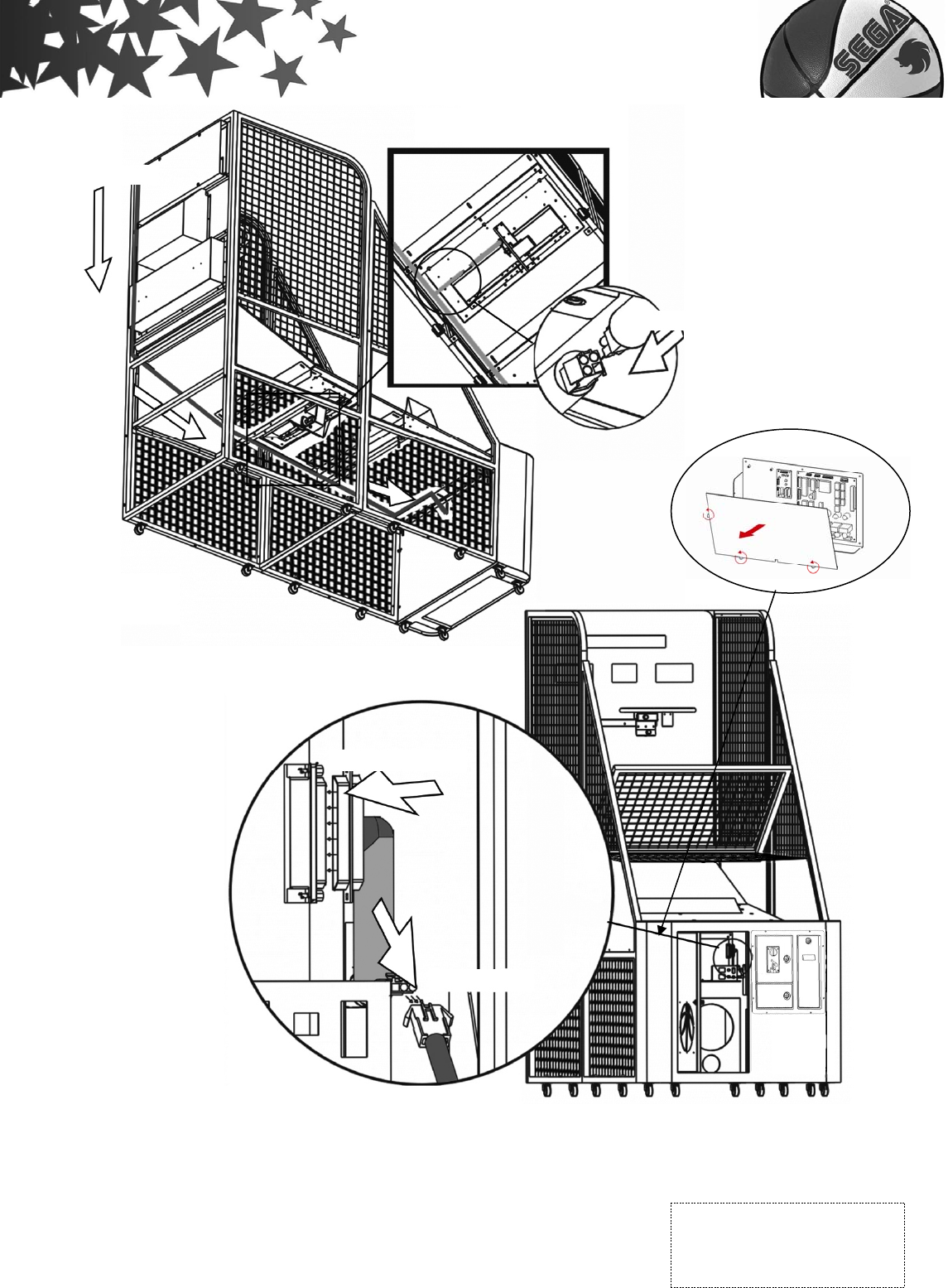
Step 8:
1.Fix the 3 main cords as the following drawing.
2.Run the IC board plug and the ball holder kit plug located underneath the front
Ball net holder kit
Metal Shelf (optional)
Main part
P.34 NO.04
screw (M8×88)×4
P.35 NO.19 nut(M8)×4
P.35 NO.27
sleeve(
φ
15
×
43)
×
4
P.34 NO.08 screw (M8×16)×4
P.35 NO.19 nut (M8)×4
P.35 NO.30 washer(M10×20)×4
P.35 NO.31
Hexagonal Phillips screw will 2
Washers included 2 on each side
- 16 -
of the ball net holder, through the hole in back of the main part.
3.Now connect plugs as shown in drawing.
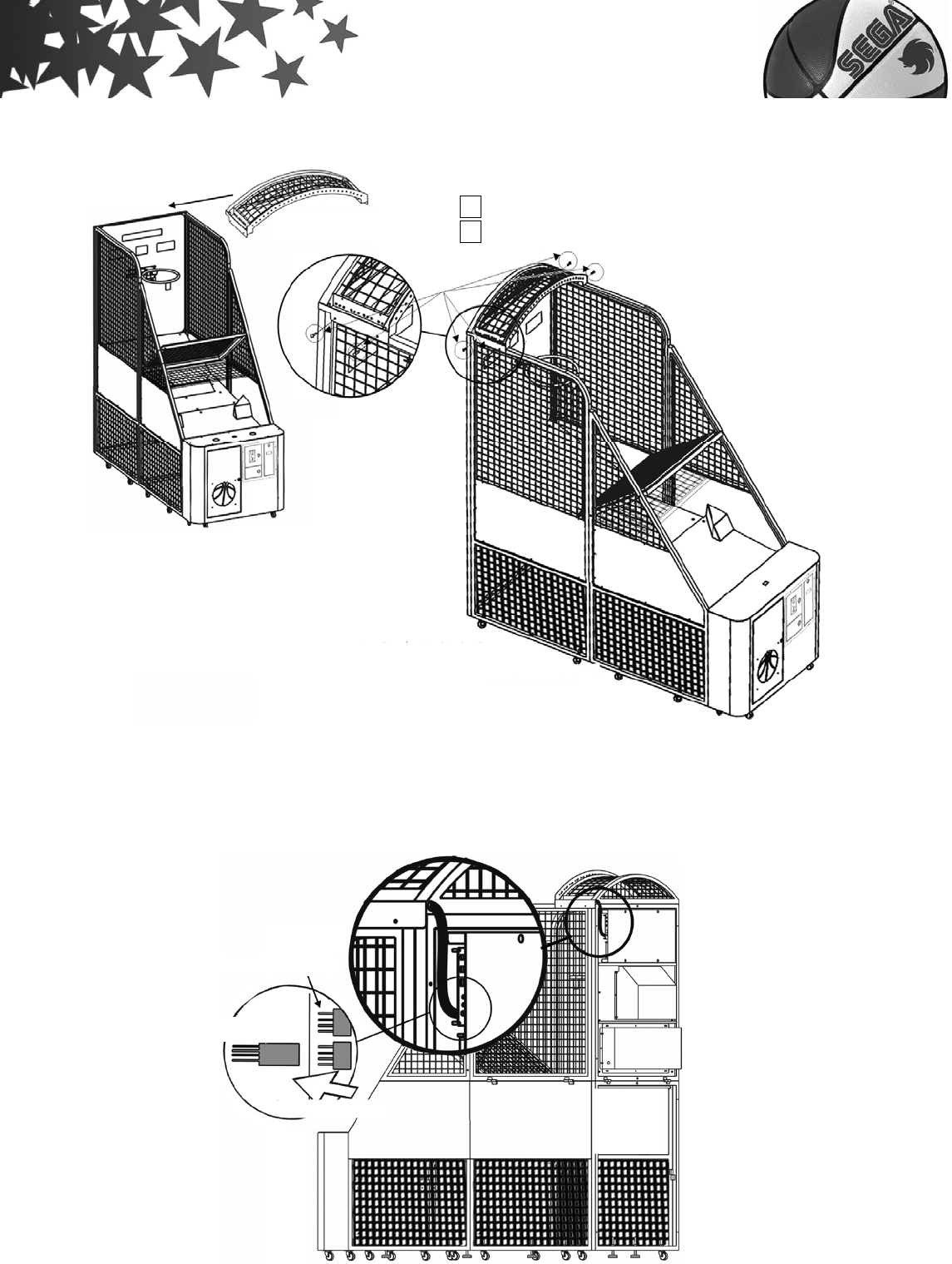
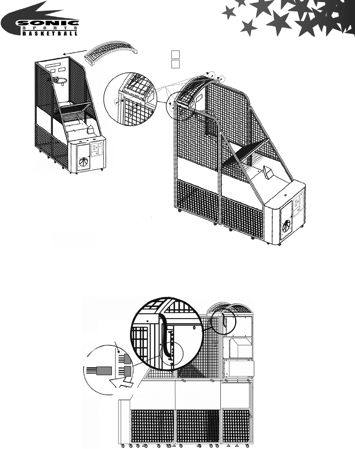
Step 9:
Screw【Top cover(optional)】step by step as drawing.
Ball holder kit
Ball holder kit plug
IC board plug
Power plug
Assembly parts
Top cover(optional)
Main cords
Open main box
base a cover
- 17 -
Step 10:
1.connect the I/O control board with Top cover.
2.Now connect plugs as shown in drawing.
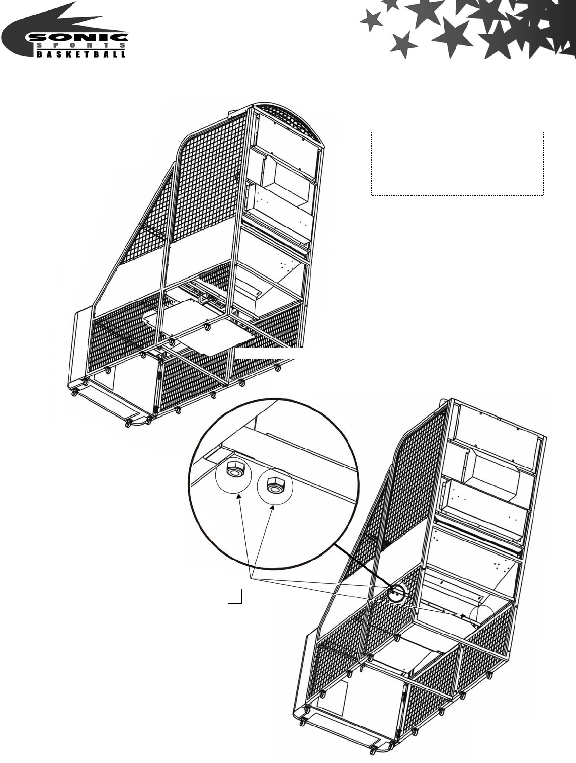
Step 11:
Top cover(optional)
I/O control Board
Top cover
Insert position
P.35 NO.28 screw (M5×38)×4
P.35 NO.29 Nut(M5)×4
- 18 -
Use screws fixed it then complete the assembly street basketball.
Assembly parts
6C Block wooden board
for motor
Block wooden board for motor
P.35 NO.20 nut(M6)×4

- 19 -
2. Assembly and disassembly for Half-Assembly type
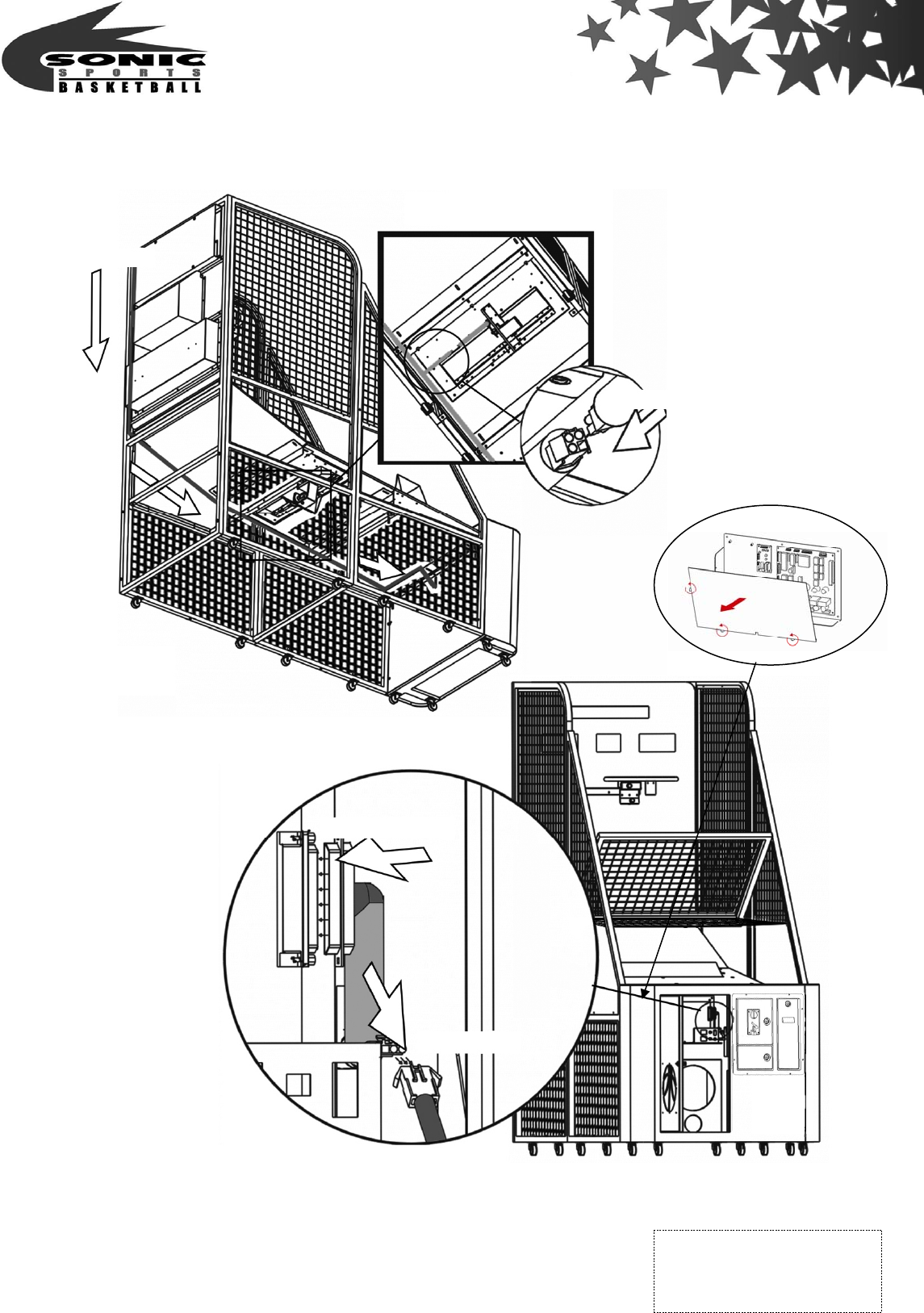
Step 1:
Turn the left and right frame180°to the position as drawing picture . connect with
screw & fixed it as drawing.
- 20 -
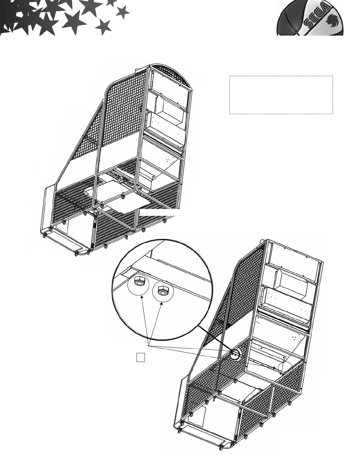
Step 2:
Screw the base frame FB and base frame FF as drawing picture.
P.34 NO.04
screw (M8×88)×4
P.35 NO.19 nut (M8)×4
- 21 -
Step 3:
Screw the 5B Ball holder kit and 5C Ball guide kits as drawing picture.
Assembly parts
4B Base holder FB
4C Base holder FF
FB
FF
P.34 NO.11
screw (M6×26)×2
P.35 NO.20 nut (M6)×2
P.34 NO.10
screw (M6×48)×4
P.35 NO.20 nut (M6)×4
- 22 -
Step 4:
Assembly parts
5B Ball holder kit
5C Ball guide kits
Ball holder kit
Ball guide kits
P.34 NO.11
screw (M6×26)×12
P.35 NO.20
nut (M6)×12
P.35 NO.30
washer(M6×26)×12
- 23 -
1. Screw【6A Ball net holder kit】.
2. Screw【6B Main part】、【Metal Shelf (optional)】.
Assembly parts:
6A Ball net holder kit
6B Main part
Metal Shelf (optional)
P.34 NO.04
screw (M8×88)×4
P.35 NO.19 nut(M8)×4
P.35 NO.27
sleeve(
φ
15
×
43)
×
4
P.34 NO.08 screw (M8×16)×4
P.35 NO.19 nut (M8)×4
P.35 NO.30
washer(M10×20)×4
Ball net holder kit
Metal Shelf (optional)
Main part
P.35 NO.31
Hexagonal Phillips screw will 2
Washers included 2 on each side

- 24 -
Step 5:
1.Fix the 3 main cords as the following drawing.
2.Run the IC board plug and the ball holder kit plug located underneath the front
of the ball net holder, through the hole in back of the main part.
3.Now connect plugs as shown in drawing.
- 25 -
Step 6:
Screw【Top cover(optional)】step by step as drawing.
Assembly parts
Top cover(optional)
Top cover(optional)
Ball holder kit
Ball holder kit plug
IC board plug
Power plug
Main cords
Open main box
base a cover
- 26 -
Step 7:
1.connect the I/O control board with Top cover.
2.Now connect plugs as shown in drawing.
Step 8:
I/O control Board
Top cover
Insert position
P.35 NO.28 screw (M5×38)×4
P.35 NO.29 Nut(M5)×4
- 27 -
Use screws fixed it then complete the assembly street basketball.
Block wooden board for motor
P.35 NO.20 nut(M6)×4
Assembly parts
6C Block wooden board
for motor
- 28 -
3.【SET-UP Position & maintenance】
V.Adjustment and Inspection
You can find the bookkeep system by opening the main part door.
IC board includes power、
fuse、Bookkeep and test
functions
Please see【1 Link adjustment】
for IC board function.
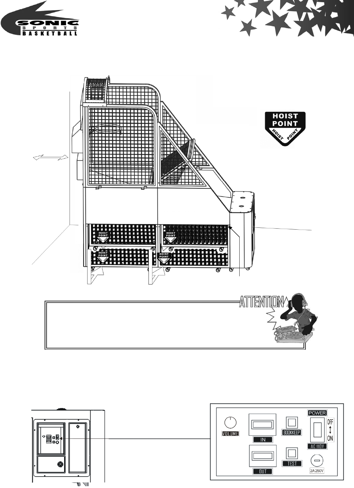
Fix position after assembly
1.Hoist the machine from the hoist
point.
2.Keep at least 50cm(20”) space
from the back for maintenance
and to avoid over heating.
Electrical plug display
50CM(20’’)
Attention:
The power must be turned off before any movements.
Check the power rate before use AC110V~120V/AC220V~240V,
Check Electrical plug display as a glide.
- 29 -
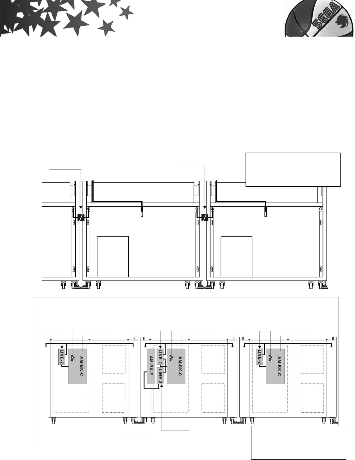
1.Link adjustment
【Cable link SET-UP】
The link set-up must follow DIP-SW-SEP-UP N0.1~15 machines.
Intermittent allowed, but repeat.
A . Link up to 15 machines
B . Only one main frame is needed.
C . Any game could be used as the main frame.
P.S. If two link machines-2 PCB are connected, the main control one DIP-SW must be set
as OFF OFF OFF ON.
The link machines must
stand side by side
The main part back view
Link Plug connect
Link
sub-board PC Board
DIPSW DIPSW DIPSW
Link Plug connect
The link machines must
stand side by side
The main part front view
Link
sub-board
Link
sub-board
PC Board PC Board
Link sub-board
Link PC board
- 30 -
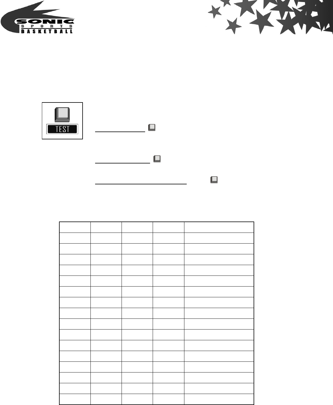
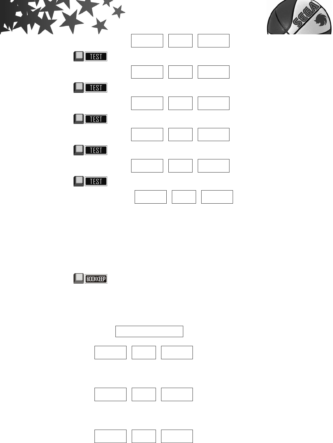
【Link main board adjustment】
Multi-function button:
1.Press and turn on the power, for 「TEST」function.
2.In Standby mold is「SERVICE」function, Press once means
one coin, but No record.
3.In bookkeep mold is「RESET」function.
4.In ticket dispenser error mode, press is「Key out」function.
Link DIP-SW adjustment:
Single mode starting display:
SW4 SW3 SW2 SW1
OFF OFF OFF OFF Single mode
OFF OFF OFF ON link 1 Unit
OFF OFF ON OFF link 2 Unit
OFF OFF ON ON link 3 Unit
OFF ON OFF OFF link 4 Unit
OFF ON OFF ON link 5 Unit
OFF ON ON OFF link 6 Unit
OFF ON ON ON link 7 Unit
ON OFF OFF OFF link 8 Unit
ON OFF OFF ON link 9 Unit
ON OFF ON OFF link 10 Unit
ON OFF ON ON link 11 Unit
ON ON OFF OFF link 12 Unit
ON ON OFF ON link 13 Unit
ON ON ON OFF link 14 Unit
ON ON ON ON link 15 Unit
- 31 -
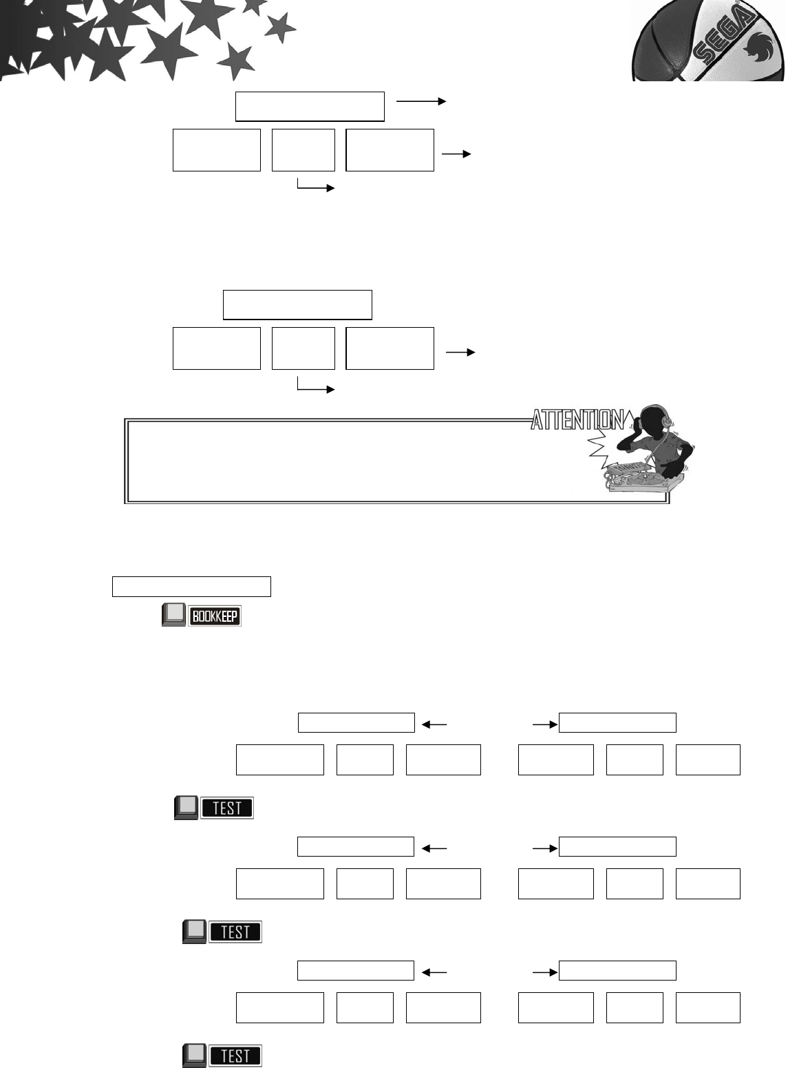
Link mode starting display:
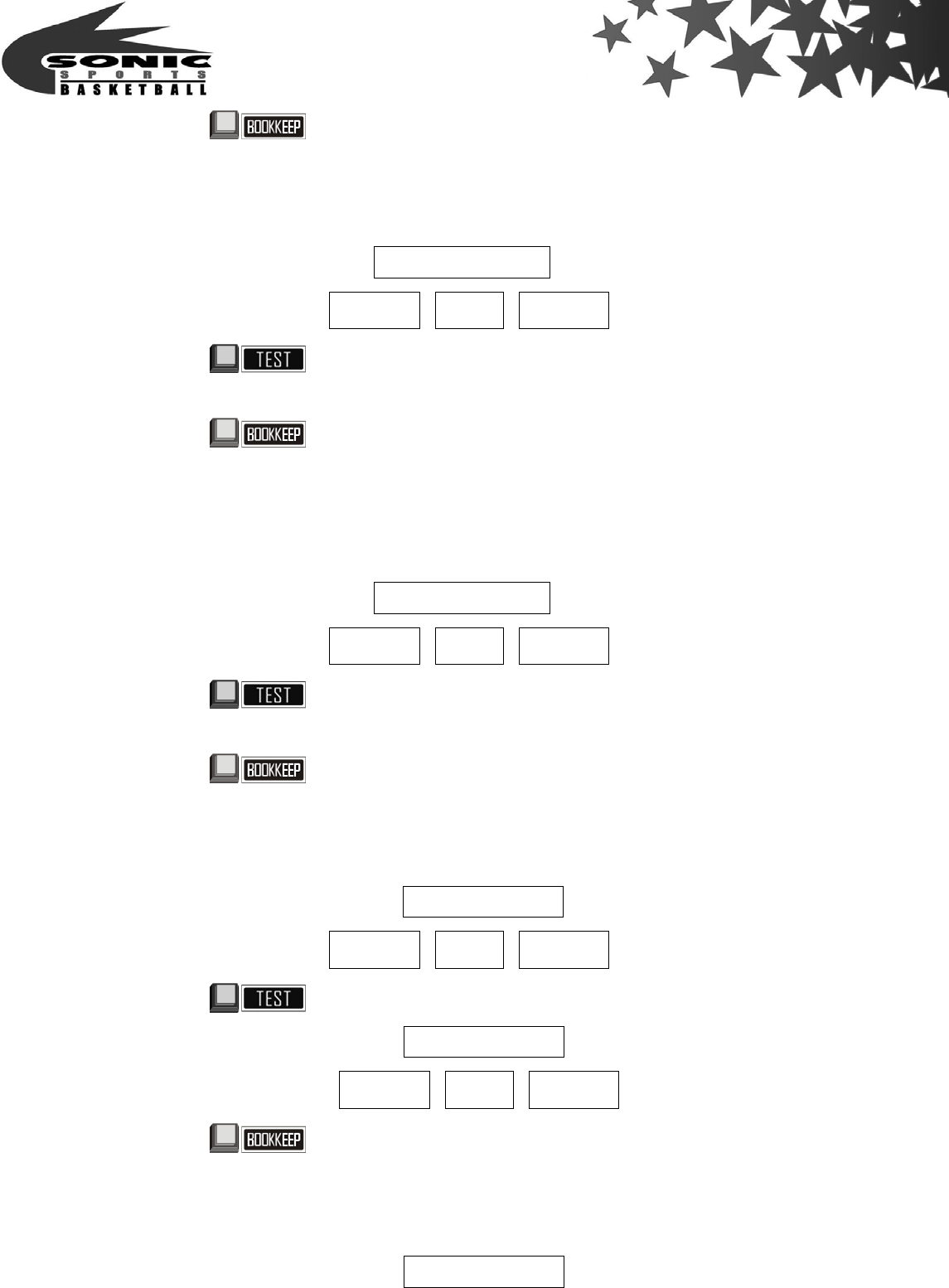
2.Adjustment
L I N E – T E S T after done the test can enter the set up.
Press and turn on the power, release the key after you hear the sound.
【SET-UP 1】SET-UP the coin entry price for each game
1 – C O I N Alternately 1 – P L A Y
_ _ 1 _ _ _ _ 1 1 _ _ _ _ _ _ 1
Press then release
2 – C O I N Alternately 1 – P L A Y
_ _ 1 _ _ _ _ 2 1 _ _ _ _ _ _ 2
Press then release
3 – C O I N Alternately 1 – P L A Y
_ _ 1 _ _ _ _ 3 1 _ _ _ _ _ _ 3
Press then release
XXXXXX
0
C
X
L I N E – T E S T
X C
X
Program type(CXX type)
Program type(CXX type)
Single mode(switch all DIP-SW off)
Link mode station NO,(XX=1-15)
Displays Company logo
When you turn on the main control machine, the other
machines will link as set situation.
- 32 -
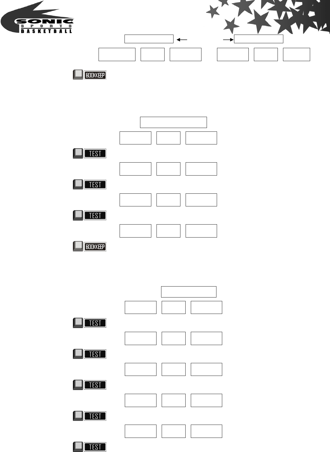
4 – C O I N Alternately 1 – P L A Y
_ _ 1 _ _ _ _ 4 1 _ _ _ _ _ _ 4
Press for then release to enter SET-UP 2
【SET-UP 2】Additional tickets
M I N – O U T
_ _ 2 _ _ _ _ 0
Press then release
_ _ 2 _ _ _ _ 1
Press then release
_ _ 2 _ _ _ _ 2
Press then release
_ _ 2 _ _ _ _ 3
Press for 1 second then release to enter SET-UP 3
【SET-UP 3】Multiple of tickets
T I C K E T
_ _ 3 _ _ _ 0 0
Press then release
_ _ 3 _ _ _ 1 0
Press then release
_ _ 3 _ _ _ 2 0
Press then release
_ _ 3 _ _ _ 3 0
Press then release
_ _ 3 _ _ _ 4 0
Press then release
No ticket, game play only
SET-UP 2 is ineffective.
10
p
oints:1 ticket
0 ticket dispensed after every
game is ended
Each time game over
Release 1 additional tickets
Each time game over
Release 2 additional tickets
Each time game over
Release 3 additional tickets
20
p
oints:1 ticket
30
p
oints:1 ticket
40
p
oints:1 ticket
- 33 -
_ _ 3 _ _ _ 5 0
Press then release
_ _ 3 _ _ _ 6 0
Press then release
_ _ 3 _ _ _ 7 0
Press then release
_ _ 3 _ _ _ 8 0
Press then release
_ _ 3 _ _ _ 9 0
Press then release
_ _ 3 _ _ 1 0 0
The explanation:
If the operator sets the game for 3____10 and the game is giving out tickets the
player will receive 1 ticket for every 10 points scored . If the operator sets the game
for 3____20 the player will get 1 ticket for every 20 points scored and so on.
For additional (0-3) tickets enter SET-UP 2
Press for 1 second then release to enter SET-UP 4
【SET-UP 4】Game Time SET-UP
GAME - TIME
_ _ 4 _ _ _ 5 0
_ _ 4 _ _ _ 5 5
_ _ 4 _ _ _ 6 0
Stage 1:50 seconds
Stage 2:40 seconds
Stage 3:30 seconds
Stage 1:55 seconds
Stage 2:45 seconds
Stage 3:35 seconds
Stage 1:60 seconds
Stage 2:50 seconds
Stage 3:40 seconds
50
p
oints:1 ticket
60
p
oints:1 ticket
70
p
oints:1 ticket
80
p
oints:1 ticket
90
p
oints:1 ticket
100
p
oints:1 ticket
- 34 -
Press for 1 second then release to enter SET-UP 5
【SET-UP 5】Basket motor AUTO test
STE–MOT-1
_ _ 5 _ _ _ _ _
Press then release-Start basketball motor AUTO test
(Warning alarm will start after 5 seconds, if there is an error)
Press for 1 second then release to enter SET-UP 6
【SET-UP 6】Ball holder motor AUTO test
STE–MOT-2
_ _ 6 _ _ _ _ _
Press then release-Start ball holder motor AUTO test
(Warning alarm will start after 5 seconds, if there is an error)
Press for 1 second then release to enter SET-UP 7
【SET-UP 7】Reset the top score 250 or keep the record
XXXXXX ÆDisplays Company logo
_ _ 7 _ _ _ _ _ Reset the top score to 250
Press then release
XXXXXX Æ Displays Company logo
_ _ 7 _ _ _ _ 1 Keep the record
Press then release to enter SET-UP 8
【SET-UP 8】SET-UP DEMO music(ON or OFF)
XXXXXX Æ Displays Company logo
- 35 -
_ _ 8 _ _ _ _ _ DEMO music OFF
Press then release
XXXXXX Æ Displays Company logo
_ _ 8 _ _ _ _ 1 DEMO music ON
Restart the Machine to complete the SET-UP adjustment.
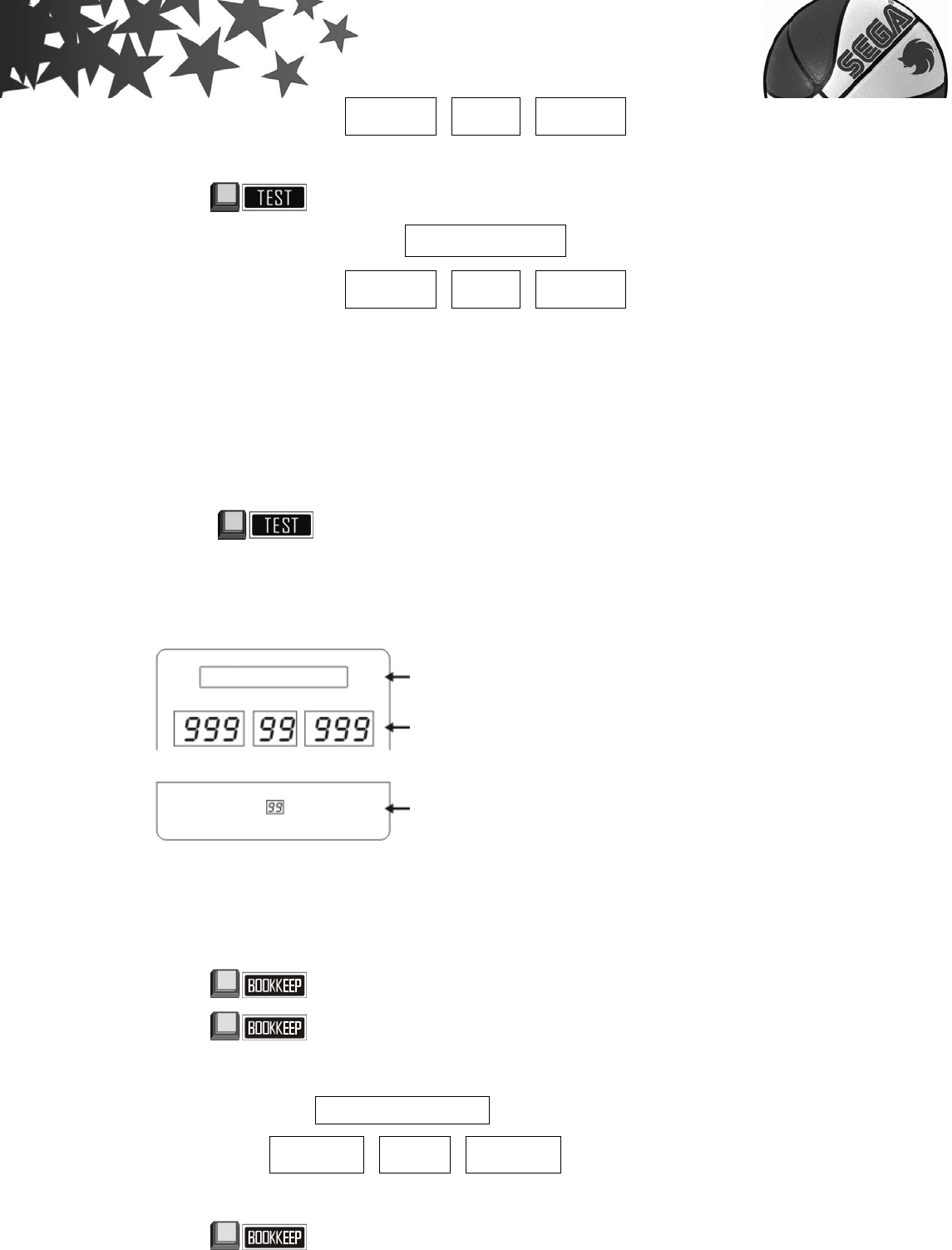
3.LED Monitor inspection
Testing:
1. Press and turn on the power in the same time to enter LED testing
mode. Release the test button until is displayed ”1” on the LED.
2.Check if the LED is displayed correctly.
3.When testing is finished you will enter into the standby function.
4.After AUTO test is finished, it will enter into standby function.
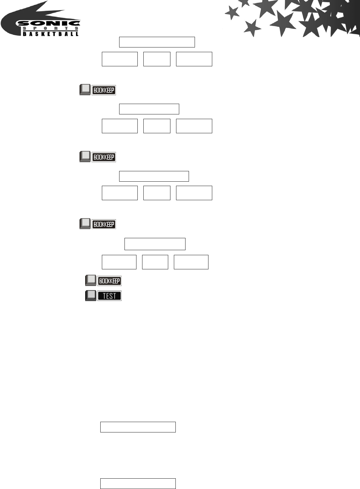
4.Bookkeep
Press enter into bookkeep system in standby function only.
Press then release, enter into【bookkeep 1】
COUNT - IN
1 C X X X X X X
Press then release, enter into【bookkeep 2】
LED test function display:
LED dis
p
la
y
s Com
p
an
y
lo
g
o
,
from ri
g
ht to left.
LED display「1 2 3 4 5 6 7 8 9」,color test change
from
「
red
」
「
green
」
then
「
orange
」
Coin LED display「1 2 3 4 5 6 7 8 9」,color test「red」.
Record total received
Coins up to 999999 same as counter,
no counter reset allowed.
XXXXXXX
X
- 36 -
COUNT - OUT
2 C X X X X X X
Press then release, enter into【bookkeep 3】
SHIFT - IN
3 C X X X X X X
Press then release, enter into【bookkeep 4】
SHIFT - OUT
3 C X X X X X X
Press then release, return back to bookkeep function【The end】
XXXXXX Æ Displays Company logo
_ _ _ 5 5 _ _ _
Press then release, enter into standby function.
Press then release, return back to【bookkeep 3】function. And reset the
【bookkeep 3】and【bookkeep 4】.
5.Error code
Every time machine is turned on it will do the AUTO test for 7 function points, Before
entering into standby function.
The Error specification as below,
【Error 1】 C O I N – 1
【Error 2】 C O I N – 2
Record total received
Coins up to 999999 same as counter,
no counter reset allowed.
Record total received
Coins up to 999999,
counter reset is allowed.
Record total dispensed tickets
up to 999999,
counter reset is allowed.
Warning alarm action
Left coin selector is disconnected
Left coin selector didn’t turn in to NC
Left coin selector error
Warning alarm action
Right coin selector is disconnected
Right coin selector didn’t turn in to NC
Ri
g
ht coin selector erro
r
- 37 -
【Error 3】 SET-MOT – 1
【Error 4】 SET-MOT – 2
【Error 5】 T I C K E T
【Error 6】 COUNT - IN
【Error 7】 COUNT-OUT
VI.How to play
1.There are total 4 Stages
A.Stage 1:Proceed to Stage 2,when the total scores are over 40 in the end.
B.Stage 2:Proceed to Stage 3,when the total scores are over 150 in the end.
C.Stage 3:Proceed to Stage 4,when the total scores are over 250 in the end.
D.Stage 4:Final challenge, the last game will be finished when the time is terminated.
Warning alarm action
Ball holder motor power is disconnected
Ball holder SENSOR-NO
Ball holder is out of position
Warning alarm action
Basket motor power is disconnected
Basket SENSOR-NO
Basket is out of
p
osition
Warning alarm action
Coin counter is disconnected
Coin counter error
Warning alarm action
Ticket dispenser is disconnected
Ticket dispenser adjustment error No tickets
Press for clean tickets.
Warning alarm action
Ticket counter is disconnected
Ticket counter tickets
- 38 -
2.2 play types available
A.Single play:DIP-SW set to single play.
B.Link mode:DIP-SW set to link mode, up to 15 machines can be linked.
Press link mode, display link countdown time, any other machine
can be linked together during the countdown. In link mode, up to
15 machines can be linked.
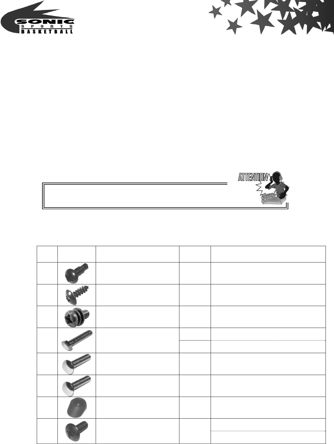
VII.Screw and Nut list
NO picture Specification Total
quantity Position
1
screw(M4×12) 68 set
2
screw (M4×10) 21 set
3
screw (M3×5) 26 set
12 Knock down machine Step 4.7
4
screw(M8×88) 8 Semi-assemble machine Step 1.4
5
screw (M5×20) 8 set
6
screw (M5×20) 8 set
7
screw (M5) 4 set
Knock down machine Step 7
8
screw(M8×16) 4
Semi-assemble machine Step 4
When the machine is in standby function, the SW is ineffectual.
- 39 -
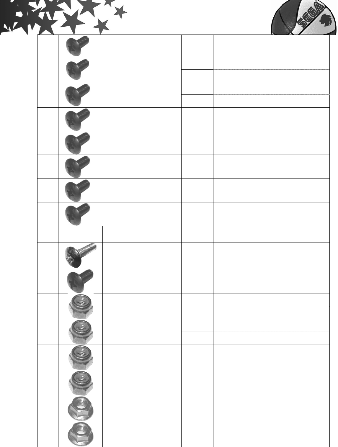
9
screw (M6×55) 1 set
14 Knock down machine Step 3.5.6
10
screw (M6×48) 12 Semi-assemble machine Step 2
20 Knock down machine Step 5.6
11
screw (M6×26) 14 Semi-assemble machine Step 2.3
12
screw (M6×16) 16 set
13
screw (M5×15) 4 Knock down machine Step 2
14
screw (M4×15) 4 set
15
screw (M4×12) 58 set
16
screw (M4×8) 8 set
NO picture Specification Total
quantity Position
17
screw (M3×12) 2 set
18
screw (M3×10) 1 set
16 Knock down machine Step 4.7
19
nut(M8) 12 Semi-assemble machine Step 1.4
38 Knock down machine Step 3.5.6.11
20
nut (M6) 20 Semi-assemble machine Step 2.3.8
21
nut (M5) 4 Knock down machine Step 2
22
nut (M4) 20 set
23
nut (M6) 4 set
24
nut (M5) 8 set
- 40 -
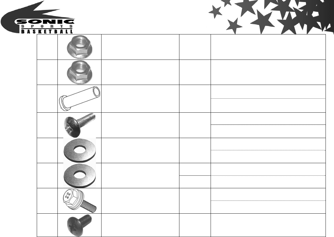
25
nut (M4) 44 set
26
nut (M3) 7 set
Knock down machine Step 7
27 sleeve (φ15×43) 4
Semi-assemble machine Step 4
Knock down machine Step 9
28
screw (M5×38) 4 Semi-assemble machine Step 6
Knock down machine Step 9
29
washer(M4×12) 4
Semi-assemble machine Step 6
24 Knock down machine Step 6.7
30
washer (M6.5×13.5) 12 Semi-assemble machine Step 3.4
Knock down machine Step 7
31
Hexagonal Phillips
screw will 2 Washers 4 Semi-assemble machine Step 4
32
screw (M4×10) 48 Knock down machine Step 1
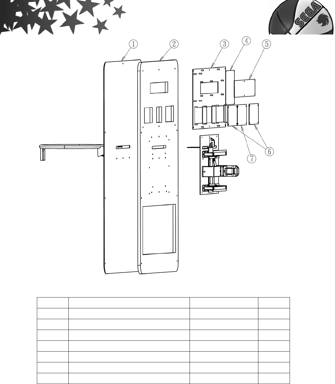
VII.Expended view
- 41 -
Item Name Part Number Quantity
1 Basket acrylic board (RoHS) J30401001 1
2 Basket board J10103003 1
3 Main wooden board J30502013 1
4 I/O control board B3 (RoHS) J10102007 1
5 Running display board (RoHS) J10102004 1
6 3 Digitals display board (RoHS) J10102006 2
7 2 Digitals display board (RoHS) J10102005 1
- 42 -
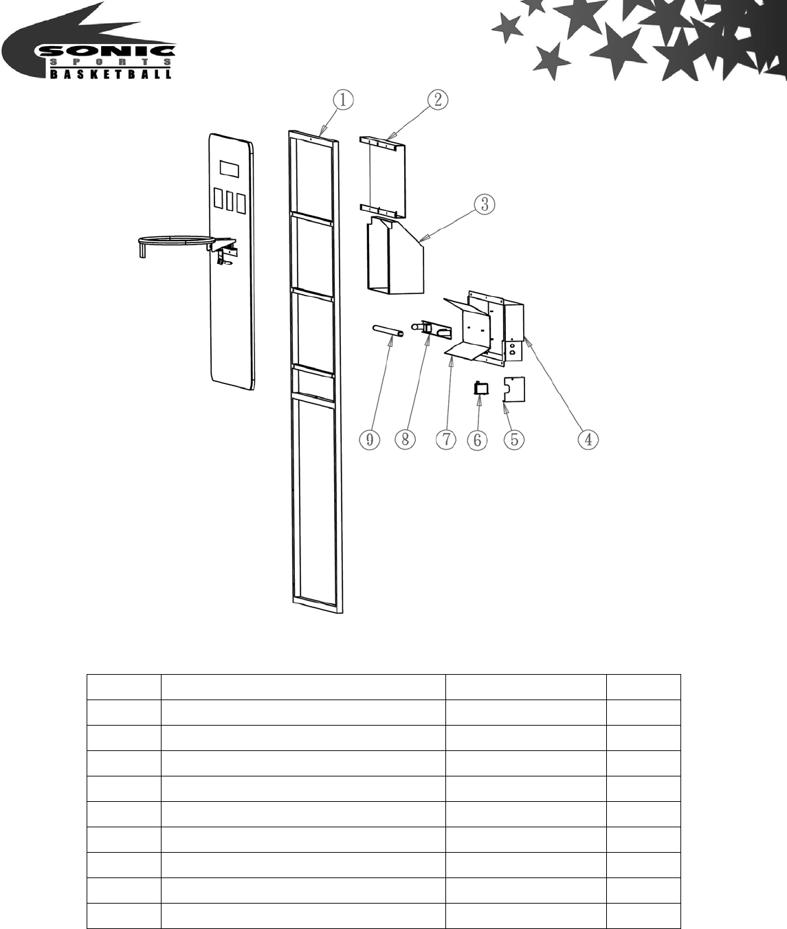
Item Name Part Number Quantity
1 Frame for main wooden board fix use J30501008 1
2 Basket upper back cover (AVR type) J30502014 1
3 Basket lower back cover J30502015 1
4 Light back cover (AVR type) J30511006 1
5 Light case J30511007 1
6 Starter A30404001 1
7 Light reflection board J30511002 1
8 Light 220V 14W A11511002 1
9 Light T5 14W A11512001 1
- 43 -
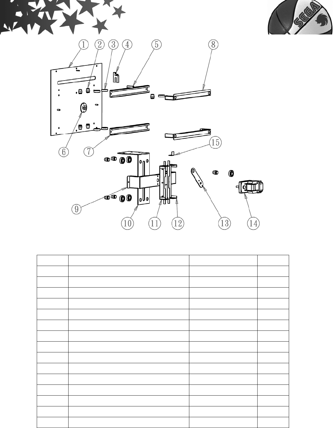
Item Name Part Number Quantity
1 Wooden board for basket unit fix use J30502007 1
2 Bearing (RoHS) J30502017 10
3 Bearing (6002ZZ) J39901002 10
4 Ball holder sensor 1.1 (RoHS) J10102009 1
5 Sliding railway for sensor J30502019 1
6 Bearing D type J30502016 1
7 Sliding railway for basket J30502012 2
8 Bearing cover J30502104 2
9 Basket motor holder J30502001 1
10 Basket holder J30502004 1
11 Basket left holder J30502107 1
12 Basket right holder J30502107 1
13 Connecting rod for basket unit J30502006 1
14 Gear motor (KGB-215-6130B1) A11301007 2
15 Basket position bard J30502103 1
- 44 -
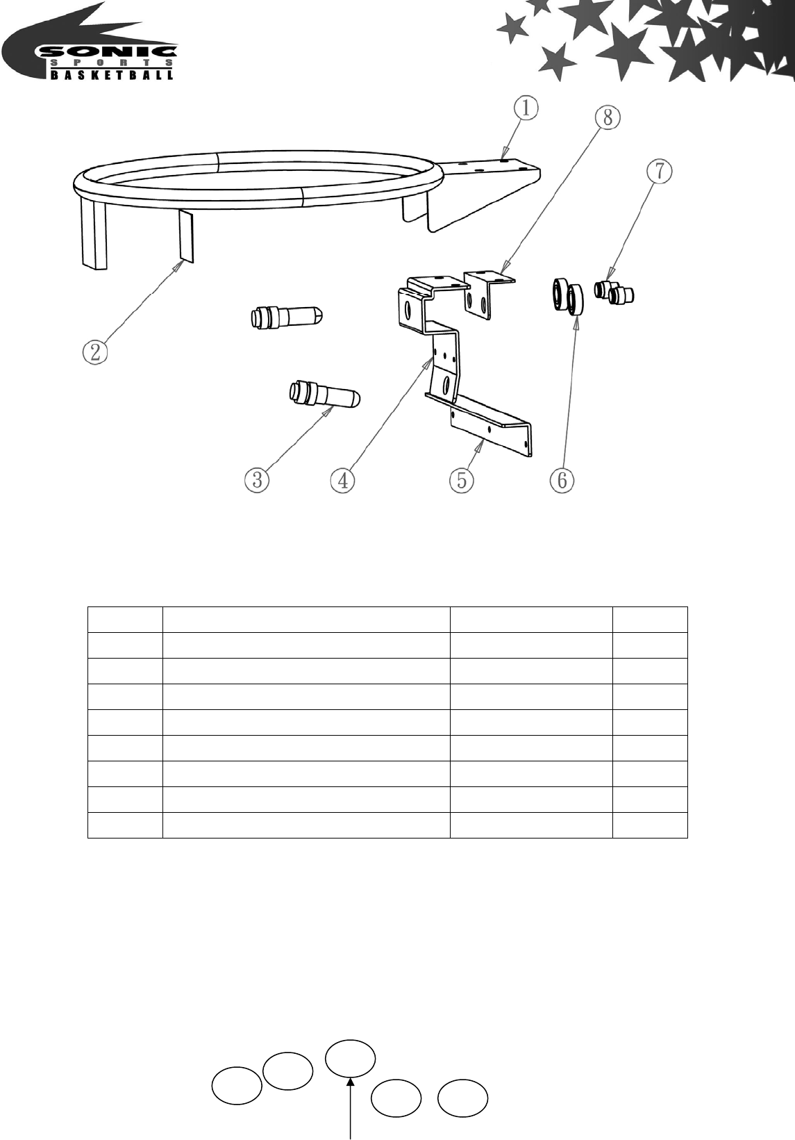
Item Name Part Number Quantity
1 Basket net set J30508034 1
2 3M reflection sticker J30304001 1
3 Basket sensor (WO-RNPW2) (RoHS) A80100003 2
4 Basket sensor holder J30502003 1
5 Basket sensor railway J30502008 1
6 Bearing (6002ZZ) J39901002 2
7 Bearing (RoHS) J30502017 2
8 Basket track holder J30502002 1
- 45 -
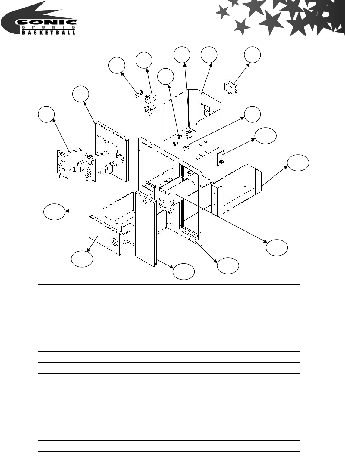
Item Name Part Number Quantity
1 Hole type cover J30503004 1
2 Link PCB (RoHS) J10102003 1
3 Main box base J30508043 1
4 Speaker cover J30503005 1
5 Main case J30511004 1
6 Main case acrylic board (RoHS) J30402001 1
7 Play button J10104001 1
8 Single main PCB (RoHS) J10102001 1
9 Play button J10104002 1
10 Transformer 220/110 2A(70414-59A) (RoHS) A10301022 1
11 Transformer (15V*2 70414-58A) (RoHS) A10301021 1
12 Transformer (15V*2 70414-58A) (RoHS) A10301021 1
13 The wooden crate takes the hand A80209008 1
14 Transformer bracket fixing J30511003 1
15 Wheel A002 without brake (RoHS) A80201102 4
16 3 in 1 Name 1
17 Speaker (PL-T70130R) (RoHS) A80100005 1
18 Speaker (10” RoHS) A11202001 1
19 Speaker box J10103006 1
20 Main box base a cover J30508044 1
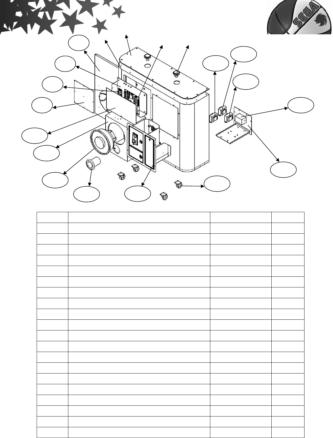
- 46 -
Item Name Part Number Quantity
1 Coin selector (SG-828) (RoHS) A10201017 2
2 Qian Daomen A80550108 1
3 Tuning Niu A30115001 1
4 PIN counter (7 number) A10503002 2
5 Push on (Red) (PB-003A) A30113001 2
6 3P power with light (RS-003D) A30103016 1
7 Counter A/C plug J30508054 1
8 Wave filter (YGD3T5) A10101003 1
9 Fuse (R3-11 20mm) A00801001 1
10 Lottery ticket small card J10102017 1
11 Ticket box A80550104 1
12 Ticket dispenser (TD-963CR) (RoHS) A10601003 1
13 Method of three-in-one skeleton A80550101 1
14 Cash box gate A80550107 1
15 Lottery ticket gate A80550102 1
16 Cash box A80550105
1
2
3
4
5
6
7
8
9
11
12
1
3
14
1
5
1
6
1
0
- 47 -
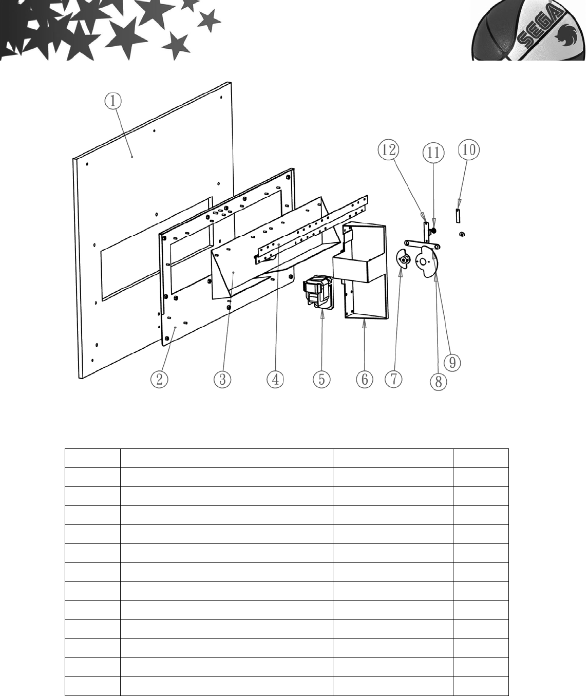
Item Name Part Number Quantity
1 Wooden board – B type J10103002 1
2 Board of ball stopper unit J30504003 1
3 Ball stopper board unit J30504004 1
4 Chain for basket (650X46.6) A80202002 1
5 Gear motor (KGB-215-6130 B1) A11301007 1
6 Motor frisked for ball stopper unit J30504001 1
7 Ball holder bearing J30504005 1
8 Ball holder bearing D type J30504008 1
9 Arm of ball stopper J30504006 1
10 Sensor SW J10102009 1
11 Bearing LF-1040 J39901001 2
12 Ball holder sensor holder J30504007 1

- 48 -
