Arcade Wacky Ducks Manual Service 11 01 07 User
2013-11-28
User Manual: Arcade Wacky Ducks Manual
Open the PDF directly: View PDF ![]() .
.
Page Count: 36
1
OWNERS AND SERVICE MANUAL
INNOVATIVE CONCEPTS IN ENTERTAINMENT INC.

2
TABLE OF CONTENTS
INTRODUCTION……………………………...…..…....PAGE 3
• GAME FEATURES
• GAME PLAY
ASSEMBLY……………….……….…………....…..…..PAGE 4 & 5
• BEFORE YOU BEGIN
• TOOLS NEEDED
• INSTALLATION
• SETTING A.C. LINE VOLTAGE ADJUSTMENTS
SET-UP / TESTING.……………………………….…....PAGE 6 - 9
• SAFETY PRECAUTIONS
• PROGRAMMING YOUR GAME
• OPTION MODES
• TESTING
SET-UP / TESTING (NEW JERSEY)..………….…....PAGE 10 - 13
• SAFETY PRECAUTIONS
• PROGRAMMING YOUR GAME
• OPTION MODES
• TESTING
QUICK TROUBLESHOOTING………….……………..PAGE 14
• PROBLEMS & SOLUTIONS
REPAIR…………………………………………………..PAGE 15 - 21
• OPERATIONAL BACKGROUND
• MECHANICAL REPAIR
• ELECTRICAL / ELECTRONIC REPAIR
• MAINTENANCE
PARTS LISTINGS………………………….………..….PAGE 22
SCHEMATICS & WIRING DIAGRAMS....…………....PAGE 23 - 35
ICEDOC WK9001
REVISION C 11-01-07

3
INTRODUCTION
GAME FEATURES
Thank you for your purchase of the new WACKY
DUCKS™ redemption game from I.C.E.
Through an exclusive agreement with JUPITER
GAMES, I.C.E. is able to bring you an innovative
product with all of the features and reliability you've
come to expect in our games.
The game is constructed of a quality 7 ply MDO ply-
wood cabinet. The cabinet is then sealed, painted
and decaled using laminated graphics that resist
most common cleaning agents. All metal parts are
powder coated for maximum beauty and durability.
The game uses creative lighting techniques to draw
game players to it and to enhance game enjoyment.
Long lasting rope light is used for the marquee that
is mounted behind a multi-color graphics panel to
create an attractive rainbow pattern. Flashing ducks
and super bright sign grade florescent lighting round
out the lighting package.
A unique cartoon like Punching Glove on a scissors
mechanism gives the game a fun way for Kids to
play the game. The mechanism has been exten-
sively tested for durability and reliability. The sole-
noid coil that drives the mechanism is fan cooled
and thermally protected. The coil is also operated on
low voltage D.C. power.
The game electronics are at the same time high
tech, yet all drive components are chosen for their
long history of reliability. Surface mount components
and programmable logic arrays keep the board size
to a minimum and the reliability to the maximum.
A high quality digital audio amplifier is used to re-
create some of the funniest sounds you'll ever hear
in a game. A variety of funny duck sounds will keep
you laughing for hours on end.
The ducks move along a belt that is powered by a
heavy-duty 12-volt gear motor. This motor has been
chosen for its long lasting and cool running capabili-
ties. It has a full-length drive shaft for greater reliabil-
ity.
All electronics are fully operator adjustable and are
adjusted via convenient programming buttons lo-
cated just inside the coin door. The game allows the
operator to choose a timed game or a random hit
game depending on the operators' location. (Please
see the Game Play section below and the program-
ming section for further information).
GAME PLAY
The game can be set up to be played in two different
ways. Both ways are described below.
TIMED GAME
The player inserts their money into the game to be-
gin. Behind the row of ducks are Frog displays that
have a "time" indicator on them. Once the player
tries to hit his first duck, the count down timer will
begin. (The timer will also begin if the player does
nothing for ten seconds or more). Once the timer
begins, the player needs to hit as many ducks as
possible before time runs out.
The player will be awarded tickets based on how
many ducks have been knocked down. The player
may also receive "mercy" tickets if they were unable
to hit any ducks.
ONE HIT GAME
In this version of the game, the player inserts his
money to start the game. Then the Frog display will
show a random number of "Tickets" that can be
won. This number will constantly continue to change
during game play. The player can hit the punch but-
ton multiple times, however the game ends once the
player hits a duck. The player then wins the tickets
that were displayed at the time of the hit.
NOTE: This game is generally set up as a "One Hit"
game. The operator can however set the game up
for a different predetermined number of hits.
4
ASSEMBLY
BEFORE YOU BEGIN
WARNING: WHEN INSTALLING THIS GAME, A 3
PRONG GROUNDED A.C. RECEPTACLE MUST
BE USED. FAILURE TO DO SO COULD RESULT
IN INJURY TO YOURSELF OR OTHERS. FAILURE
TO USE A GROUNDED RECEPTACLE COULD
ALSO CAUSE IMPROPER GAME OPERATION,
OR DAMAGE TO THE ELECTRONICS
DO NOT DEFEAT OR REMOVE THE GROUNDING
PRONG ON THE POWER CORD FOR THE SAME
REASON AS GIVEN ABOVE. USING AN IMPROP-
ERLY GROUNDED GAME COULD VOID YOUR
WARRANTY.
HAVE A QUALIFIED ELECTRICIAN CHECK
YOU’RE A.C. RECEPTACLE TO BE SURE THE
GROUND IS FUNCTIONING PROPERLY.
TOOLS NEEDED
To assemble your game you will need a 7/16" socket
or box wrench.
Note: For normal game servicing you will need two
different size Allen wrenches which are provided.
INSTALLATION
1. Remove the cardboard box from the pallet.
2. Cut banding that holds the game to the pallet.
NOTE: BE SURE TO STAND TO THE SIDE WHEN
CUTTING THE BANDS, AS THEY ARE UNDER
PRESSURE, AND COULD SPRING OUT CAUSING
INJURY.
3. Remove all of the shrink-wrap and packaging
from the game and marquee.
4. Find the location that the game will be placed
in and move into rough position.
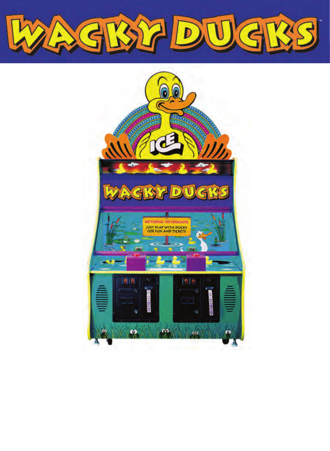
5. Remove the "Wacky Ducks™ sign on the front
of the game by rotating the two locks, and
lifting up on them.
6. Remove the 7/16" bolts and fender washers
from the rear of the game. There are five of
these.
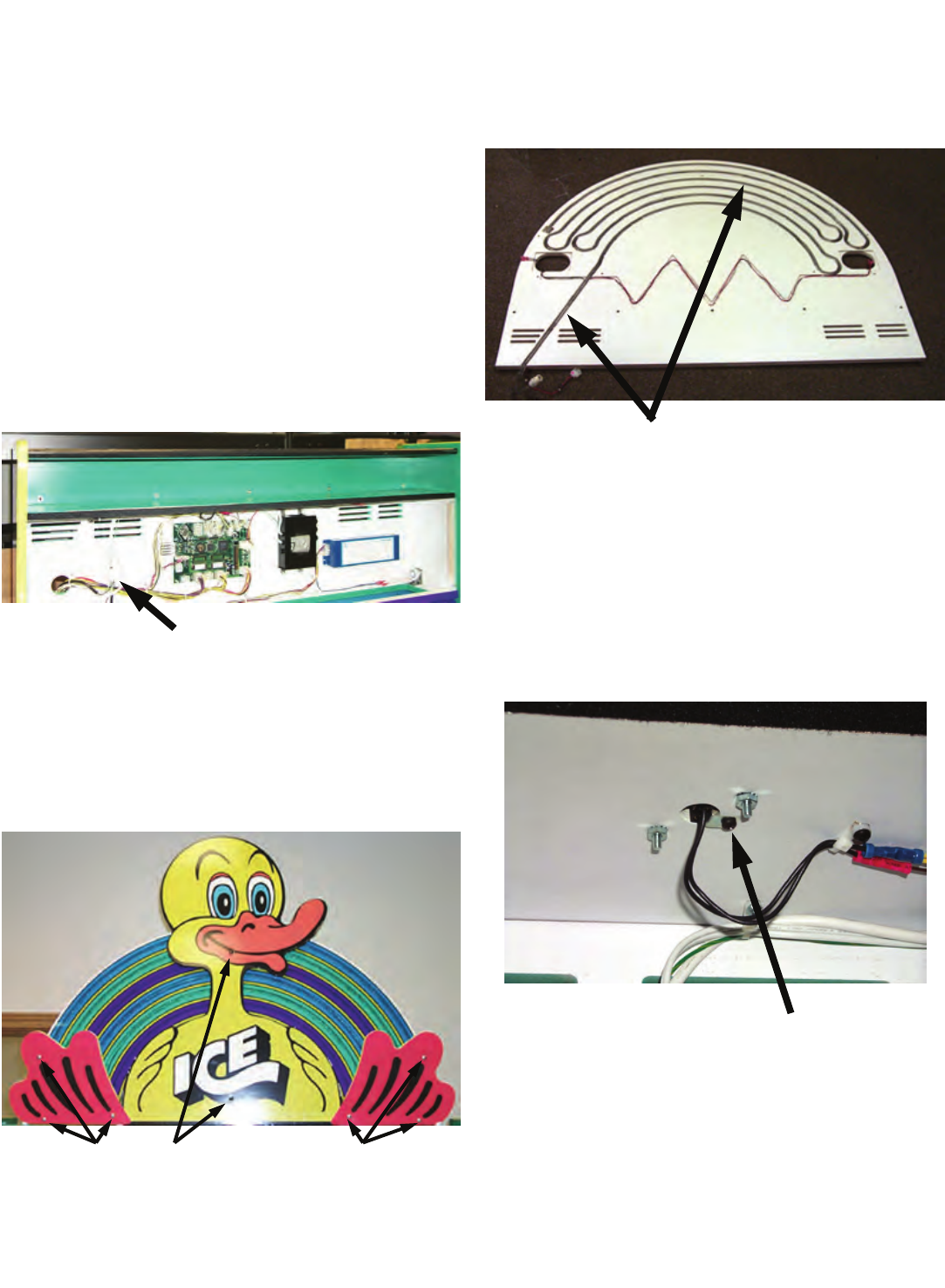
7. Get someone to help and move the
Duck / rainbow marquee into position. Insert
the rope light and speaker wires through the
hole in the back of the game. Tighten the bolts
to the marquee.
8. Inside the game, connect the rope light and
speaker wires.
LOCKS
INSERT WIRES HERE
MOUNTING
BOLTS

5
SETTING A.C. LINE
VOLTAGES
The game comes with 4 available line voltage set-
tings as described below. These settings should be
used to provide A.C. power in the correct range to
the game without over or under powering it.
POWER RANGE VOLTAGE SETTING
90-110 V.A.C. 115
110-130 V.A.C. 125
200-220 V.A.C. 230
220-250 V.A.C. 250
The game uses a POWER MODULE to handle all of
the A.C. power distribution chores of the game. It
incorporates an On-Off switch, primary A.C. game
fusing, and power switching capabilities. This allows
the game to be used with a wide variety of A.C. volt-
ages by re-strapping the main transformer.
A.C. LINE VOLTAGE
ADJUSTMENT
To adjust the game for a different A.C. voltage:
• Unplug the game from the outlet.
• Disconnect the power cord from the power
module.
• Using a small flat blade screwdriver, pry the
fuse holder from the power module.
• Notice a small window on the fuse holder
with an arrow that points to the voltage the
game is presently set at.
• Using a small flat blade screwdriver, lift the
retaining tab that holds the voltage selector
in the fuse holder.
• Rotate the voltage selector until the voltage
you want is displayed in the voltage select
window.
• Push the voltage selector back into the fuse
holder until it snaps into place. NOTE: Do not
force the selector into the fuse holder. If it
does not go in easily, it is not being installed
correctly.
ASSEMBLY
• Snap the fuse holder assembly back into the
power module.
• Plug the power cord back into the receptacle
in the power module, and into the wall outlet.
NOTE: WHEN CHANGING VOLTAGES FROM THE
115-125 TO 230-250 RANGE, LOWER THE MAIN
FUSE AMPERAGE VALUE BY ½.
WHEN CHANGING FROM THE 230-250 TO 115-
125 VOLT RANGE, DOUBLE THE MAIN FUSE AM-
PERAGE VALUE.
Plug the game in, turn the power on and play a
couple of game. Pay attention to the sound vol-
ume of the game.
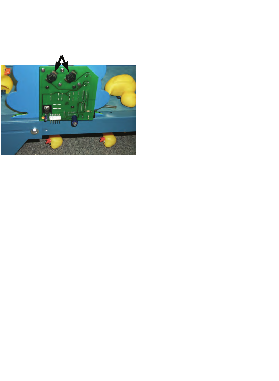
ADJUSTING VOLUME
There are two volume control potentiometers on the
Main P.C. Board. The top one controls the theme
music and the bottom one controls the sound effects
such as Duck sounds, etc. Adjust these during game
play.
FINAL ASSEMBLY
After the volume is adjusted, proceed to the set up /
testing section to prepare the game for your location.
When all testing is done, re-install the "Wacky
Ducks™ Sign, remove the keys, and roll the game
into its final location. Lower the adjustable leg level-
ers to keep the game from moving.
YOUR GAME IS NOW READY TO PLAY. IF
YOU HAVE ANY FURTHER QUESTIONS OR
COMMENTS REGARDING THE GAME,
PLEASE CALL OUR SERVICE DEPARTMENT
AT 1-716-859-0360

6
SET-UP / TESTING
SAFETY PRECAUTIONS
WARNING: WHEN INSTALLING THIS GAME, A 3
PRONG GROUNDED A.C. RECEPTACLE MUST
BE USED. FAILURE TO DO SO COULD RESULT
IN INJURY TO YOURSELF OR OTHERS. FAILURE
TO USE A GROUNDED RECEPTACLE COULD
ALSO CAUSE IMPROPER GAME OPERATION,
OR DAMAGE TO THE ELECTRONICS
DO NOT DEFEAT OR REMOVE THE GROUNDING
PRONG ON THE POWER CORD FOR THE SAME
REASON AS GIVEN ABOVE. USING AN IMPROP-
ERLY GROUNDED GAME COULD VOID YOUR
WARRANTY.
HAVE A QUALIFIED ELECTRICIAN CHECK
YOU’RE A.C. RECEPTACLE TO BE SURE THE
GROUND IS FUNCTIONING PROPERLY.
REPLACE ALL INCANDESCENT BULBS WITH
PROPER ICE SUPPLIED BULBS ONLY.
PROGRAMMING YOUR GAME
This section will give you a detailed explanation of
the functions and operating characteristics of each
of the programming buttons.
PLEASE READ THIS SECTION CAREFULLY TO
AVOID PROBLEMS WITH YOUR GAME.
PLEASE NOTE: THE PROGRAMMING AND
TICKET RESET BUTTONS ARE LOCATED IN-
SIDE THE LEFT HAND COIN DOOR. ADDITION-
ALLY, THERE IS A SINGLE TICKET RESET BUT-
TON INSIDE THE RIGHT HAND COIN DOOR.
DISPLAY INFORMATION
THE RIGHT HAND FROG DISPLAY WILL SHOW
YOU THE OPTION YOU ARE IN. THE LEFT HAND
DISPLAY WILL SHOW THE VALUE OR SETTING
FOR THAT OPTION.
PROGRAMMING BUTTON
Press this button to enter or exit the PROGRAM-
MING mode. You will notice when you are in the
Programming mode, as the displays in the Frogs will
change.
SELECT BUTTON
This button is used to change from one option to the
next. When this button is pushed, the option number
is shown in the display window of the RIGHT HAND
Frog.
ADVANCE
This button is used to change the value within the
option. When this button is pushed, the value will be
shown in the LEFT HAND Frog.
TICKET RESET BUTTON
When the game runs out of tickets, it keeps track of
how many are owed. When more tickets are in-
serted, the game will attempt to dispense all of the
tickets that are still owed. If the operator does not
wish to dispense these tickets when reloading, press
the "Ticket Reset" button BEFORE replacing the
tickets. The tickets Reset buttons are located inside
the coin doors.
OPTION MODES
MODE 0
(COINS PER CREDIT)
This option determines how many coins are neces-
sary to start a game. The range for this game is 1-
10. The default value for this mode is "1"

7
SET-UP / TESTING
MODE 1
(GAME LENGTH)
This mode determines how long the game lasts in
SECONDS. The range for this value is 5-60.
The default value for this game is "10"
MODE 2
(COIN OR CREDIT COUNTER)
This mode determines if the coin counter will count
coins or credits. (Example: If it takes 3 coins to start
a game, then 3 coins would equal 1 credit). Setting a
"0" equals coins. Setting a "1" equals credits. The
default value for this option is "0".
MODE 3
(TIME BETWEEN HITS)
This mode determines how long the game will make
the player wait between hits of the punching glove.
The number shown X 100 milliseconds equals the
actual time. (Example: 10 X 100 milliseconds equal
1 second). The range for this option is 10-50 (1 to 5
seconds). The default value for this option is "10"
MODE 4
(DUCKS PER XX TICKET DISPENSE)
This option determines how many ducks must be
knocked down each time XX tickets can be dis-
pensed. (See OPTION 5 for value of XX) The range
for this option is 1-9. The default value for this option
is "1".
FOR EXAMPLE, if the value set in OPTION 4 is "2"
and the value set in OPTION 5 is "3", the game
would dispense 3 tickets for every 2 ducks knocked
down.
MODE 5
(VALUE OF XX)
This option determines the number of tickets to dis-
pense each time a dispense order is given by OP-
TION MODE 4. The range for this option is 1-9. The
default value for this option is "1".
MODE 6
(JUST FOR PLAYING TICKETS)
This mode determines the amount of "Mercy" tickets
paid to the customer ion the event that they do not
win any tickets during normal game play. The range
for this option is 0-99. The default value for this op-
tion is "3"
NOTE: THIS OPTION FUNCTIONS IN THE TIMED
GAME MODE ONLY.
MODE 7
(ATTRACT TIME)
This mode determines the period of time between
attract modes. The numbers in this option represent
minutes. The range for this option is 0-90. Setting a
"0" equals turning the attract mode OFF. The default
value for this option is "3
MODE 8
(ATTRACT MODE TYPE)
This option determines which type of attract mode is
set.
0= Mode Disabled
1= Audio only
2= Motion only
3= both motion and audio
The default value for this option is "3"

8
SET-UP / TESTING
MODE 9
(FACTORY RESET)
This mode has the capability to reset all options to
the factory default values. The range for this option
is 0-1. Setting a "1" will reset all values. The default
value for this option is "0" (no reset)
NOTE: THE GAME CAN ALSO BE RESET TO
FACTORY DEFAULT VALUES BY TURNING THE
GAME OFF, REMOVING THE BATTERY FROM
THE MAIN P.C. BOARD. , WAIT A FEW MINUTES
THEN TURN THE GAME BACK ON.
THE ABOVE PROCEDURE IS ALSO VALUABLE IF
FOR SOME REASON THE GAME ELECTRONICS
WERE TO LOCK OR FREEZE UP.
GAME TESTING
After you have completed the set-up of your game,
INSTALL TICKETS into the game, and play a few
games to make sure everything is working properly.
Check the following:
· Check the ticket dispenser to be sure the
proper amount of tickets is given.
· Check to be sure the duck belt is tracking
properly. If not, check the mechanical repair
section for adjustment procedures.
· Be sure all external fasteners like those of
the cover glass and puncher housings are
installed and tight.
9
SET-UP / TESTING
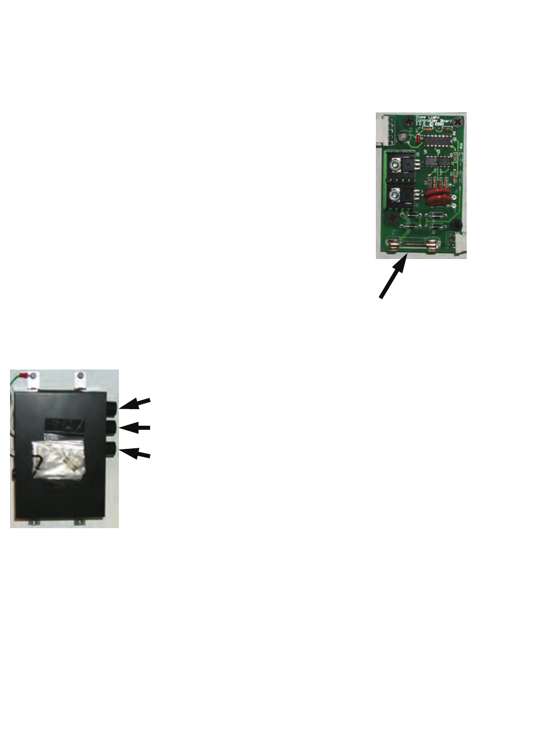
ROPE LIGHTING
The rope light in the marquee is operated by a rope
light controller located behind the WACKY
DUCKS™ sign.
Determine which type of controller is installed in your
game. (See photos)
If you have the type shown in the photo below, use
the following instructions:
Check to see that the rope light controller is set as
follows:
1. The "CHASE" mode switch should be set to
position #2.
2. The "SPEED" mode knob should be turned
fully clockwise, then rotated back about ¼
inch.
NOTE: THE "SOUND" MODE KNOB IS NOT USED.
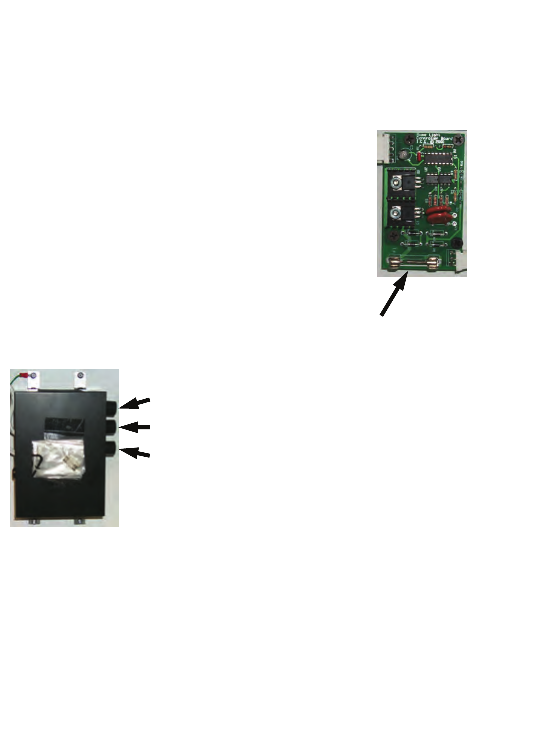
If you have the type shown in the photo below, there
are no adjustments. The fuse located at the bottom
of the printed board is the only user serviceable
item.
IF YOU HAVE ANY QUESTIONS REGARDING
THE PROGRAMMING OPTIONS, PLEASE
CONTACT OUR SERVICE DEPARTMENT
PHONE: 1-716-759-0360
FAX: 1-716-759-0884
E-MAIL: service@icegame.com
SOUND CONTROL
SPEED CONTROL
CHASE CONTROL
FUSE

10
SET-UP / TESTING
NEW JERSEY
SAFETY PRECAUTIONS
WARNING: WHEN INSTALLING THIS GAME, A 3
PRONG GROUNDED A.C. RECEPTACLE MUST
BE USED. FAILURE TO DO SO COULD RESULT
IN INJURY TO YOURSELF OR OTHERS. FAILURE
TO USE A GROUNDED RECEPTACLE COULD
ALSO CAUSE IMPROPER GAME OPERATION,
OR DAMAGE TO THE ELECTRONICS
DO NOT DEFEAT OR REMOVE THE GROUNDING
PRONG ON THE POWER CORD FOR THE SAME
REASON AS GIVEN ABOVE. USING AN IMPROP-
ERLY GROUNDED GAME COULD VOID YOUR
WARRANTY.
HAVE A QUALIFIED ELECTRICIAN CHECK
YOU’RE A.C. RECEPTACLE TO BE SURE THE
GROUND IS FUNCTIONING PROPERLY.
PROGRAMMING YOUR GAME
This section will give you a detailed explanation of
the functions and operating characteristics of each
of the programming buttons.
PLEASE READ THIS SECTION CAREFULLY TO
AVOID PROBLEMS WITH YOUR GAME.
PLEASE NOTE: THE PROGRAMMING AND
TICKET RESET BUTTONS ARE LOCATED IN-
SIDE THE LEFT HAND COIN DOOR. ADDITION-
ALLY, THERE IS A SINGLE TICKET RESET BUT-
TON INSIDE THE RIGHT HAND COIN DOOR.
DISPLAY INFORMATION
THE RIGHT HAND FROG DISPLAY WILL SHOW
YOU THE OPTION YOU ARE IN. THE LEFT HAND
DISPLAY WILL SHOW THE VALUE OR SETTING
FOR THAT OPTION.
PROGRAMMING BUTTON
Press this button to enter or exit the PROGRAM-
MING mode. You will notice when you are in the
Programming mode, as the displays in the Frogs will
change.
SELECT BUTTON
This button is used to change from one option to the
next. When this button is pushed, the option number
is shown in the display window of the RIGHT HAND
Frog.
ADVANCE
This button is used to change the value within the
option. When this button is pushed, the value will be
shown in the LEFT HAND Frog.
TICKET RESET BUTTON
When the game runs out of tickets, it keeps track of
how many are owed. When more tickets are in-
serted, the game will attempt to dispense all of the
tickets that are still owed. If the operator does not
wish to dispense these tickets when reloading, press
the "Ticket Reset" button BEFORE replacing the
tickets. The tickets Reset buttons are located inside
the coin doors.
OPTION MODES
MODE 0
(COINS PER CREDIT)
This option determines how many coins are neces-
sary to start a game. The range for this game is 1-
10. The default value for this mode is "1"

11
SET-UP / TESTING
NEW JERSEY
MODE 1
(GAME LENGTH)
This mode determines how long the game lasts in
SECONDS. The range for this value is 5-60.
The default value for this game is "10"
SETTING A "0" FOR THIS MODE WILL PUT THE
GAME INTO THE "RANDOM TICKET" MODE.
MODE 2
(COIN OR CREDIT COUNTER)
This mode determines if the coin counter will count
coins or credits. (Example: If it takes 3 coins to start
a game, then 3 coins would equal 1 credit). Setting a
"0" equals coins. Setting a "1" equals credits. The
default value for this option is "0".
MODE 3
(TIME BETWEEN HITS)
This mode determines how long the game will make
the player wait between hits of the punching glove.
The number shown X 100 milliseconds equals the
actual time. (Example: 10 X 100 milliseconds equal
1 second). The range for this option is 10-50 (1 to 5
seconds). The default value for this option is "10"
MODE 4
(DUCKS PER XX TICKET DISPENSE)
NOT USED
MODE 5
(VALUE OF XX)
This option determines the number of tickets to dis-
pense each time a dispense order is given by OP-
TION MODE 4. The range for this option is 1-9. The
default value for this option is "1".
MODE 6
(JUST FOR PLAYING TICKETS)
This mode determines the amount of "Mercy" tickets
paid to the customer in the event that they do not
win any tickets during normal game play. The range
for this option is 0-99. The default value for this op-
tion is "3". Tickets are paid up front.
NOTE: THIS OPTION FUNCTIONS IN THE TIMED
GAME MODE ONLY.
MODE 7
(ATTRACT TIME)
This mode determines the period of time between
attract modes. The numbers in this option represent
minutes. The range for this option is 0-90. Setting a
"0" equals turning the attract mode OFF. The default
value for this option is "3
MODE 8
(ATTRACT MODE TYPE)
This option determines which type of attract mode is
set.
0= Mode Disabled
1= Audio only
2= Motion only
3= both motion and audio
The default value for this option is "3"

12
SET-UP / TESTING
NEW JERSEY
MODE 9
(FACTORY RESET)
This mode has the capability to reset all options to
the factory default values. The range for this option
is 0-1. Setting a "1" will reset all values. The default
value for this option is "0" (no reset)
NOTE: THE GAME CAN ALSO BE RESET TO
FACTORY DEFAULT VALUES BY TURNING THE
GAME OFF, REMOVING THE BATTERY FROM
THE MAIN P.C. BOARD. , WAIT A FEW MINUTES
THEN TURN THE GAME BACK ON.
THE ABOVE PROCEDURE IS ALSO VALUABLE IF
FOR SOME REASON THE GAME ELECTRONICS
WERE TO LOCK OR FREEZE UP.
GAME TESTING
After you have completed the set-up of your game,
INSTALL TICKETS into the game, and play a few
games to make sure everything is working properly.
Check the following:
· Check the ticket dispenser to be sure the
proper amount of tickets is given.
· Check to be sure the duck belt is tracking
properly. If not, check the mechanical repair
section for adjustment procedures.
Be sure all external fasteners like those of the cover
glass and puncher housings are installed and tight.
13
SET-UP / TESTING
NEW JERSEY
ROPE LIGHTING
The rope light in the marquee is operated by a rope
light controller located behind the WACKY
DUCKS™ sign.
Determine which type of controller is installed in your
game. (See photos)
If you have the type shown in the photo below, use
the following instructions:
Check to see that the rope light controller is set as
follows:
1. The "CHASE" mode switch should be set to
position #2.
2. The "SPEED" mode knob should be turned
fully clockwise, then rotated back about ¼
inch.
NOTE: THE "SOUND" MODE KNOB IS NOT USED.
If you have the type shown in the photo below, there
are no adjustments. The fuse located at the bottom
of the printed board is the only user serviceable
item.
IF YOU HAVE ANY QUESTIONS REGARDING
THE PROGRAMMING OPTIONS, PLEASE
CONTACT OUR SERVICE DEPARTMENT
PHONE: 1-716-759-0360
FAX: 1-716-759-0884
E-MAIL: service@icegame.com
SOUND CONTROL
SPEED CONTROL
CHASE CONTROL
FUSE

14
QUICK TROUBLESHOOTING
GAME WILL NOT START NO A.C. POWER CHECK POWER AT A.C. RECEPTACLE
POWER MODULE SET INCORRECTLY CHECK VOLTAGE SETTING
FUSE BAD IN POWER MODULE CHECK OR REPLACE FUSE
FUSE BAD ON MAIN P.C. BOARD CHECK OR REPLACE FUSE
NO CREDITS INSERT PROPER AMOUNT OF COINS
BAD COIN MICRO SWITCH CHECK OR REPLACE MICRO SWITCH
BAD TRANSFORMER CHECK TRANSFORMER VOLTAGES
BAD GAME HARNESSING CHECK W / METER & REPAIR IF NEEDED
BAD MAIN P.C. BOARD REPAIR OR REPLACE MAIN P.C. BOARD
DUCKS WILL NOT MOVE BAD DRIVE MOTOR REPLACE DRIVE MOTOR
BAD DRIVE TRANSISTOR REPAIR OR REPLACE MAIN P.C. BOARD
NO CREDITS IN GAME ADD CREDITS TO GAME
BAD FUSE ON MAIN P.C. BOARD CHECK OR REPLACE FUSE
BELT BINDING SEE MANUAL FOR BELT ADJUSTMENT
TICKETS WILL NOT DISPENSE BAD TICKET DISPENSER CHECK FOR JAMS OR REPLACE
BAD GAME HARNESSING CHECK W / METER & REPAIR IF NEEDED
NO TICKETS IN GAME ADD TICKETS TO GAME
GAME PROGRAMMED IMPROPERLY RE-PROGRAM TICKET DISPENSE OPTION
DUCK MARQUEE WON'T LIGHT CHECK CONTROL UNIT FOR POWER IS SWITCH TURNED ON
OR FLASHES INCORRECTLY BAD FUSE ON ROPE LIGHT P.C. BOARD CHECK OR REPLACE FUSE
IS LIGHT CONTROL SET CORRECTLY SEE SET-UP FOR DIRECTIONS
ROPE LIGHT NOT CONNECTED HOOK UP ROPE LIGHTING
ROPE LIGHT BAD OR SHORTED REPLACE ROPE LIGHTING
DISPLAY DUCKS WILL NOT BAD LIGHT BULB CHECK AND REPLACE BULB
LIGHT OR FLASH OR STAYS BAD HARNESSING CHECK W / METER & REPAIR IF NEEDED
LIT BAD TRANSISTOR ON MAIN BOARD REPAIR OR REPLACE MAIN P.C. BOARD
FROG DISPLAYS DON'T WORK BAD FROG DISPLAY REPAIR OR REPLACE P.C. BOARD
OR WORK INCORRECTLY. BAD HARNESSING CHECK W / METER & REPAIR IF NEEDED
EYE LIGHTS DON'T FLASH BAD LIGHT BULB REPLACE BULB
NO SCORE WHEN DUCKS BAD FROG DISPLAY REPAIR OR REPLACE P.C. BOARD
ARE KNOCKED OVER BAD MICRO SWITCH REPLACE MICRO SWITCH
MICRO SWITCH WIRE BENT WRONG REBEND WIRE FOR OPTIMUM CONTACT
BAD HARNESSING CHECK W / METER & REPAIR IF NEEDED
NO FLORESCENT LIGHTING BAD FLORESCENT BULB REPLACE BULB
BAD LIGHT BALLAST REPLACE BALLAST
BAD WIRING CHECK W / METER & REPAIR IF NEEDED
NO SOUND OR SOUND LOW BAD SPEAKER REPLACE SPEAKER
BAD WIRING CHECK W / METER & REPAIR IF NEEDED
VOLUME SET TOO LOW ADJUST VOLUME (SEE MANUAL)
PUNCHING GLOVE DOESN'T BAD DRIVE TRANSISTOR REPAIR OR REPLACE MAIN P.C. BOARD
WORK OR WORKS SLOWLY BAD THERMAL SWITCH TEST OR REPLACE SWITCH
BAD COOLING FAN REPLACE FAN
BAD PUSH BUTTON SWITCH CHECK OR REPLACE SWITCH
BAD HARNESSING CHECK W / METER & REPAIR IF NEEDED

15
GAME REPAIR
OPERATIONAL
BACKGROUND
The WACKY DUCKS™ game has been designed to
be as easy as possible to repair.
The duck belt can be easily adjusted while in the
game, yet can be removed easily from the game if
replacement should ever become necessary.
The punching mechanisms have been designed for
easy access by simply removing the access covers.
TROUBLESHOOTING PHILOSOPHY
To find problems with the game, always first check
what should be obvious. See that the game is
plugged in, and that all of the fuses on the game are
good. This includes the fuse that is located INSIDE
the power module.
Next, check to see that all of the connectors are
firmly seated and that none of the wires have been
pulled out of them.
When trying to find out if specific components are
bad or not, try swapping them with components from
another player station to see if the problem moves
with the component, or stays where it was. This will
help you to know if you have a problem with a spe-
cific component, or maybe a problem with either the
wiring or the Main P.C. Board.
Use extreme caution when using probes or voltme-
ters if the game is powered up. If doing continuity
checks, it is important to disconnect the harnessing
at both ends, as attached they may yield erroneous
results.
If a P.C. Board is suspected as the cause of a prob-
lem, check to see that all of the components on the
board are firmly attached. Pay special attention to
any socketed devices.
If light bulbs are suspected, swap them with one that
is known to work to narrow the problem down to ei-
ther a bulb or P.C. Board.
MECHANICAL REPAIR
PUNCHING GLOVE ASSEMBLY
OVERVIEW
The punching glove system is designed for high reli-
ability and safety. The assembly can be designed
with simplicity in mind, as the solenoid is driven for
maximum pull in strength.
The solenoid is driven by approximately 35 DC volts.
This voltage may be higher or lower depending on
your A.C. voltage at the wall.
The solenoid is fan cooled to allow for higher volt-
ages that will in turn provide the higher pull in
strength.
Since fan cooling is necessary under a high game
play mode, the solenoid is protected by a bi-metal
thermal switch that is strapped directly to the sole-
noid bobbin. This switch assures that if the fan fails,
the solenoid power will be shut down before the coil
could be damaged.
The thermal switch is run "IN LINE" with the solenoid
power. This simple arrangement is very reliable and
easy to troubleshoot.
TESTING THE COIL
TESTING FOR POWER - Disconnect the coil from
the connectors. Using a voltmeter, measure that
voltage is present during game play if the punch but-
ton is pressed. There should be a voltage of 30+
volts D.C. If you do not see this much voltage, but
do see some, your meter is probably too slow to see
the voltage, as it is only on for approximately 100
milliseconds. If you don't see any voltage at all, the
solenoid driver F.E.T. on the main P.C. Board could
be bad. It could also be that the push button is not
sending a signal to the main P.C. Board.
If you see voltage to the coil, but the mechanism
won't fire, check that the thermal switch is working
correctly. When the thermal switch is cool, discon-
nect the wires from its leads and do a continuity test
across the switch terminals. You should see continu-
ity. If you don't, the switch needs to be replaced.
16
GAME REPAIR
If you see that the thermal switch is good, check to
see that the coil and the diode on the coil are good.
Disconnect the coil and unsolder 1 side of the diode.
Do a resistance check to see that there is infinite
resistance in one direction. If there is no resistance
in either direction the diode is bad. If the diode is
bad, there is also a chance that the drive transistor
and / or fuse could be bad as well.
If the diode tests good, check to see the resistance
of the coil. It should measure approximately 3.8
ohms. This resistance will vary some depending on
the temperature of the coil. If the resistance is sig-
nificantly more or less, the coil should be replaced.
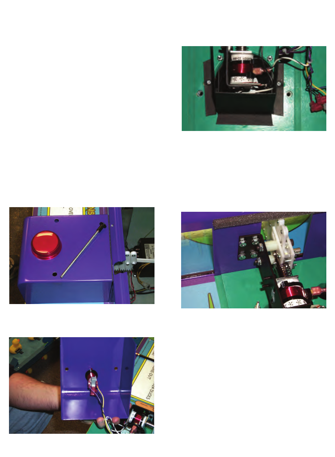
COIL REPLACEMENT
1. Remove the 2 bolts that hold the punching mech
cover in place.
2. Disconnect the micro switch assembly from the
push button and remove the cover.
3. Remove the 2 square drive screws that hold the
cardboard fan shroud in place.
4. Remove the wires that attach to the solenoid.
5. Remove the 4 screws that hold the assembly
into the cabinet. NOTE: IF THERE ARE SPAC-
ERS TO ADJUST THE SOLENOID ANGLE BE-
TWEEN THE PUNCHER BRACKET AND CABI-
NET, BE SURE TO USE THEM IN THE SAME
PLACE WHEN REASSEMBLING THE GAME.
17
GAME REPAIR
6. Remove the hex nuts that secure the 2 long
shoulder bolts to the puncher mounting bracket.
Unscrew the two shoulder bolts from the puncher
mounting bracket. The puncher assembly should
now be able to be removed.
7. Remove the 2 screws that hold the coil retaining
bracket to the puncher bracket. The solenoid
may now be removed.
8. Assemble in the reverse order.
NOTE: WHEN RE-ASSEMBLING THE PUNCHER
ASSEMBLY, BE SURE TO USE LOCK-TITE ON
THE SHOULDER BOLT THREADS AND RETAIN-
ING NUTS.
DUCK BELT ASSEMBLY
ADJUSTMENT AND REPAIR
There are two different adjustments that should be
occasionally performed on the belt assembly.
The first is an adjustment to get the proper amount
of tension to the duck belt. This is important to pre-
vent the ducks from hanging too low on the bottom
of the belt, and to help insure proper tracking.
The second type of adjustment is to set the tracking
accurately to the center of the belt board.
NOTE: BOTH OF THE ABOVE ADJUSTMENTS
ARE NECESSARY WHEN THE BELT NO LONGER
RUNS CENTERED ON THE BELT BOARD OR
WHEN REPAIRS TO THE DUCK BELT ASSEMBLY
ARE PERFORMED.
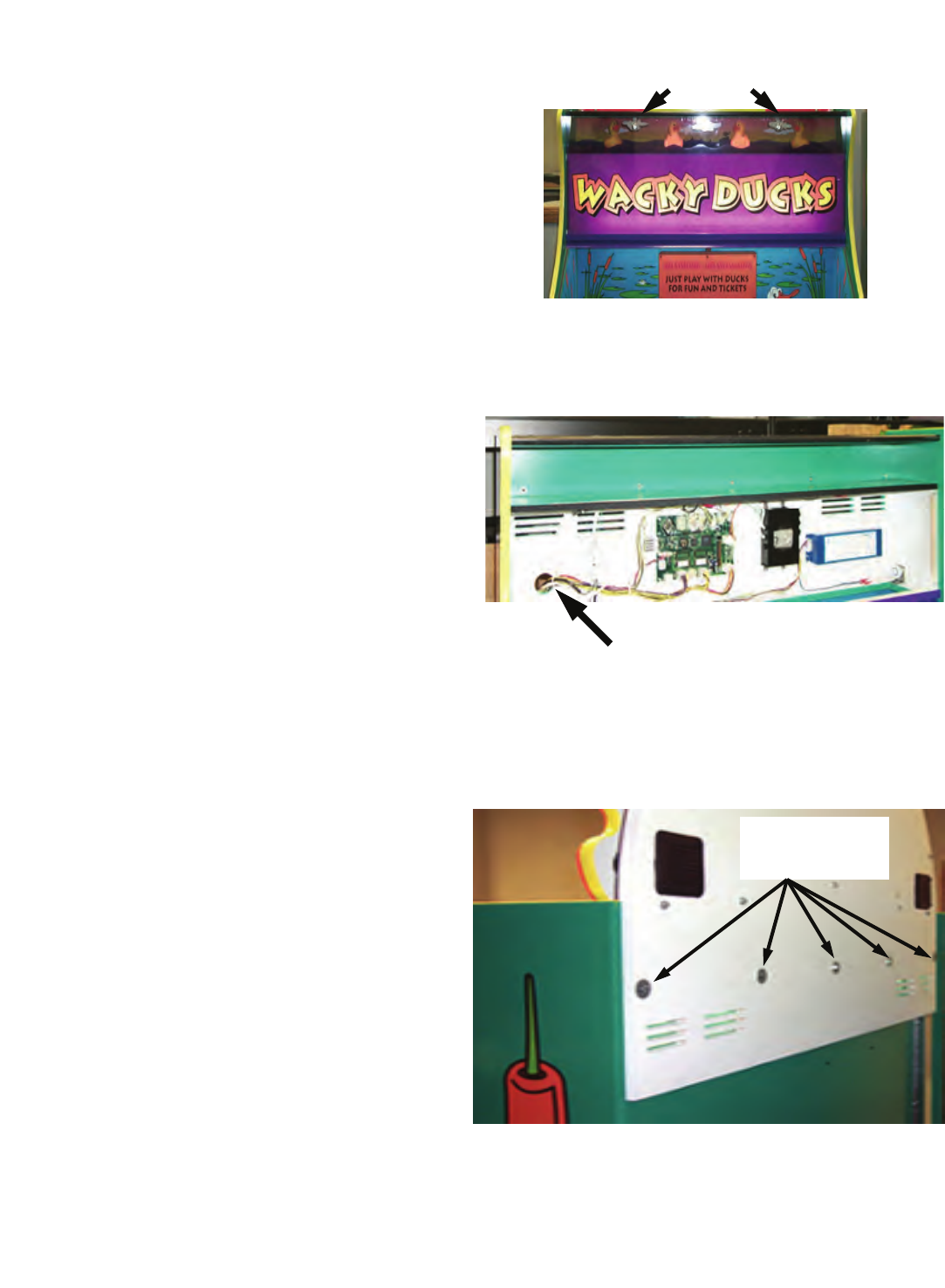
MOTOR REPAIR
1. Turn off A.C power
2. Remove cover glass by removing the 4 Allen
screws that hold the glass retainer.
3. Remove the Masonite "pond" covers that are
held in place with Velcro.
4. Remove the wires that are connected to the D.C.
motor. NOTE: MARK THE WIRES TO BE
SURE THE MOTOR DOES NOT RUN BACK-
WARDS WHEN THE GAME IS POWERED
BACK ON. IF THE BELT RUNS BACKWARDS
THE BELT COULD BE SEVERELY DAMAGED.
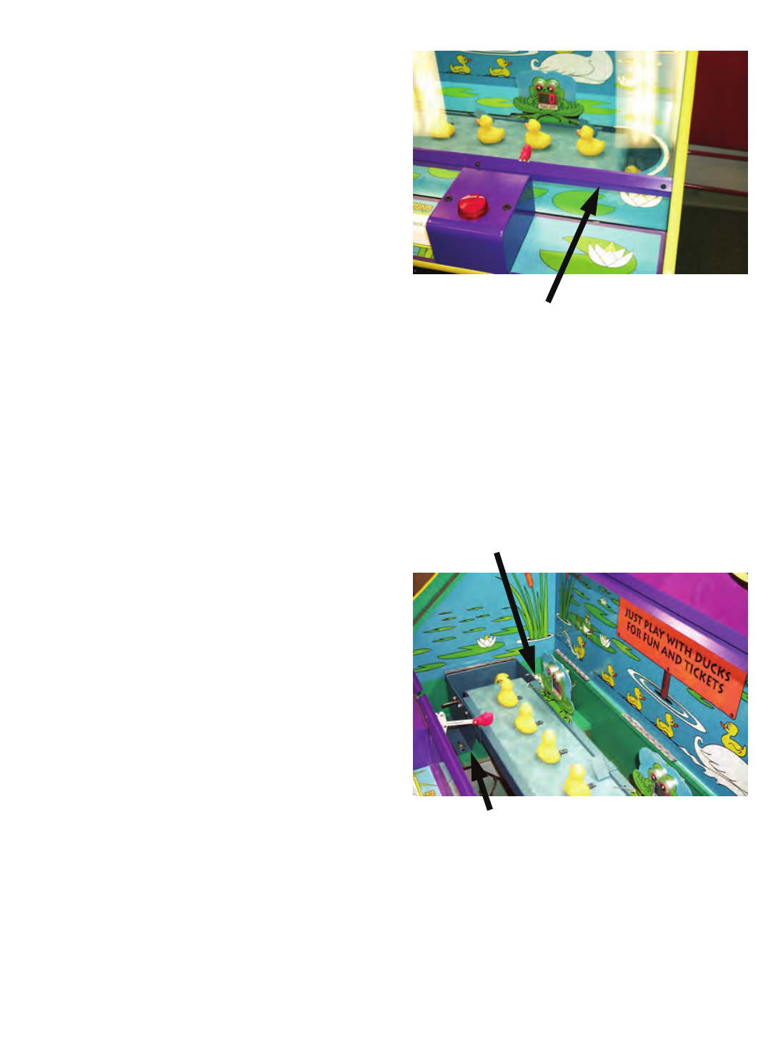
CONVEYOR MOUNTING BOLTS ARE
LOCATED IN THIS AREA ON BOTH SIDES
1. Remove the 4 bolts that hold the belt assembly
into the game.
2. Remove the belt assembly from the game. BE
CAREFUL NOT TO SCRATCH THE GAME
WHEN REMOVING THE ASSEMBLY. Place the
assembly on a suitable work surface.
GLASS RETAINER
MOTOR WIRES ON THIS END
18
GAME REPAIR
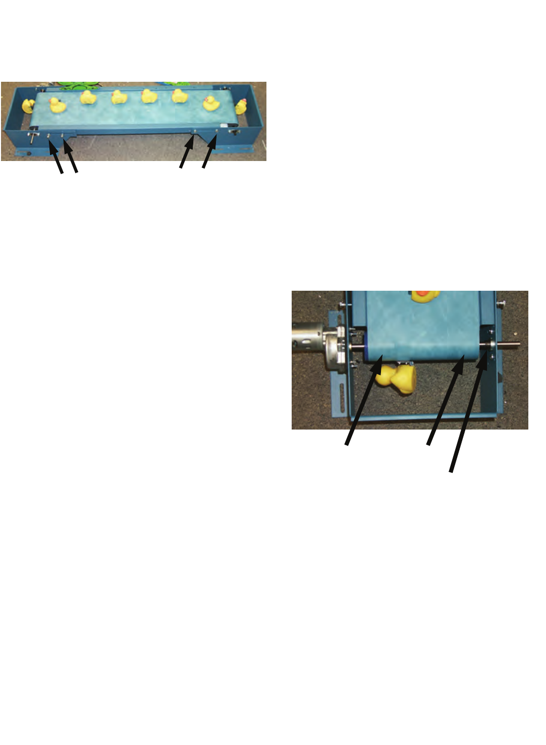
7. Loosen the 4 adjusting bolts on BOTH ends of
the assembly to loosen up the duck belt.
LOOSEN THESE SCREWS
(BOTH SIDES)
8. On the DRIVE MOTOR SIDE of the assembly,
pull the belt to the side and loosen the 2 Allen
set screws that hold the drive roller to the motor
shaft.
9. Loosen the Allen set screws that holds the small
roller bearing to the motor shaft.
10. Remove the 4 screws and nuts that hold the mo-
tor to the assembly.
11. RE-ASSEMBLE IN THE REVERSE ORDER.
12. NOTE: TIGHTEN THE SCREWS THAT HOLD
THE MOTOR TO THE ASSEMBLY JUST TIGHT
ENOUGH TO JUST SQUEEZE THE GASKET
MATERIAL. OVER TIGHTENING COULD
CAUSE SHAFT MIS-ALIGNMENT AND / OR
EXCESSIVE MOTOR NOISE.
13. FOLLOW THE DUCK BELT ADJUSTMENT
PROCEDURES AT THE END OF THIS SEC-
TION.
BELT REPLACEMENT
1. Turn off A.C power
2. Remove cover glass by removing the 4 Allen
screws that hold the glass retainer.
3. Remove the Masonite "pond" covers that are
held in place with Velcro.
4. Remove the wires that are connected to the D.C.
motor. NOTE: MARK THE WIRES TO BE SURE
THE MOTOR DOES NOT RUN BACKWARDS
WHEN THE GAME IS POWERED BACK ON.
IF THE BELT RUNS BACKWARDS THE BELT
COULD BE SEVERELY DAMAGED.
5. Remove the 4 bolts that hold the belt assembly
into the game.
6. Remove the belt assembly from the game. BE
CAREFUL NOT TO SCRATCH THE GAME
WHEN REMOVING THE ASSEMBLY. Place the
assembly on a suitable work surface.
7. Loosen the 4 adjusting bolts on BOTH ends of
the assembly to loosen up the duck belt.
8. On the DRIVE MOTOR SIDE of the assembly,
pull the belt to the side and loosen the 2 Allen
set screws that hold the drive roller to the motor
shaft.
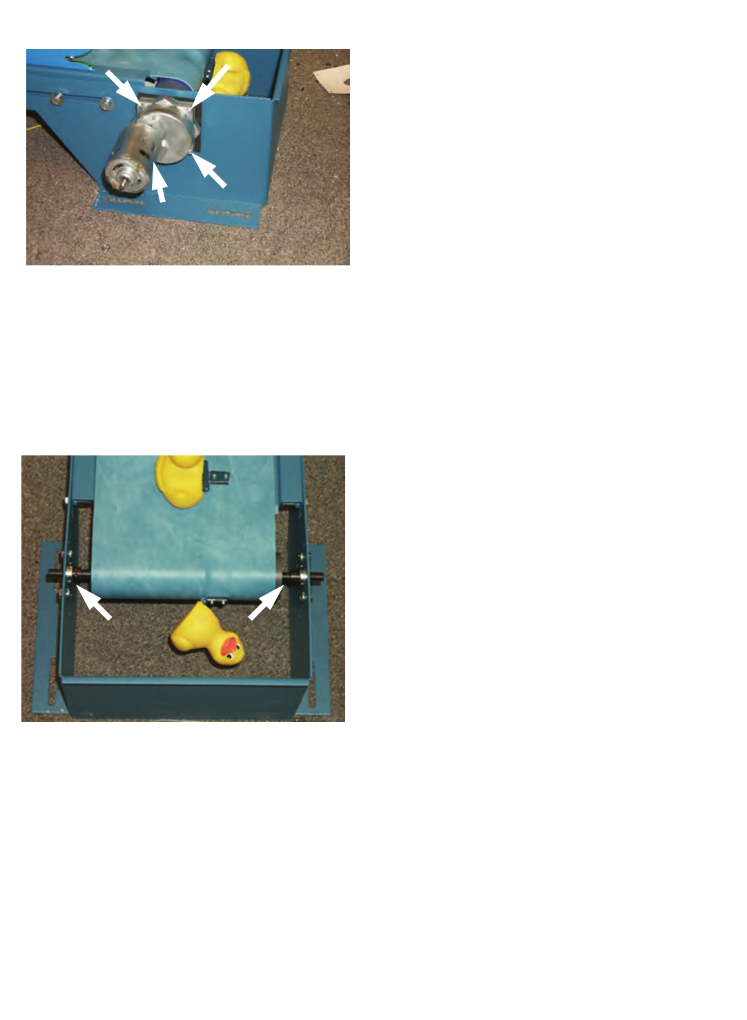
SET SCREWS UNDER BELT
BEARING SET SCREW
9. Loosen the Allen set screw that holds the small
roller bearing to the motor shaft.
10. Remove the 4 screws and nuts that hold the mo-
tor to the assembly.
19
GAME REPAIR
MOTOR MOUNTING SCREWS
11. On the IDLER ROLLER side of the assembly,
pull the belt to the side and loosen the 2 Allen
set screws that hold the drive roller to the motor
shaft.
12. Loosen the Allen setscrews that hold the idler
roller shaft and slide the shaft out.
LOOSEN THESE SCREWS
13. Remove the 4 adjusting bolts on both ends of
the assembly, separate the end brackets and
remove the belt.
14. RE-ASSEMBLE IN THE REVERSE ORDER.
15. NOTE: TIGHTEN THE SCREWS THAT HOLD
THE MOTOR TO THE ASSEMBLY JUST TIGHT
ENOUGH TO JUST SQUEEZE THE GASKET
MATERIAL. OVER TIGHTENING COULD
CAUSE SHAFT MIS-ALIGNMENT AND / OR
EXCESSIVE MOTOR NOISE.
6. FOLLOW THE DUCK BELT ADJUSTMENT
PROCEDURES AT THE END OF THIS SEC-
TION.
DUCK BELT ADJUSTMENT
1. PRELIMINARY ADJUSTMENT - Loosen the 4
bolts that hold the duck belt assembly to the
cabinet. They should be loose enough that the
entire unit can be slid back and forth easily.
2. Loosen the eight bolts that are used to tighten
the belt. There are 4 bolts on each end.
3. Loosen the bolts that secure the roller bearings
to the assembly, and re-tighten them at the mid-
point of their adjustment slots.
4. Tighten the bolts on the idler roller end of the
assembly about ½" from the innermost position.
5. Pull on the motor end of the assembly to remove
slack from the belt.
6. NOTE: WHEN THE BELT SLACK IS AD-
JUSTED PROPERLY THERE WILL BE NO
MORE THAN 2 INCHES OF DROOP ON THE
BOTTOM SIDE OF THE BELT.
7. If there is more than 2 inches, retighten the belt.
8. FINAL ADJUSTMENT - Start a game and notice
how the belt track.
9. If the belt tracks to one particular side, loosen
the bolts that adjust the roller bearings and move
the roller in or out for proper tracking. This can
be done during a game when the belt is moving,
if done carefully.
10. It may be necessary to adjust both ends once or
twice to get the optimum tracking.
20
GAME REPAIR
11. NOTICE: DO NOT LET THE BELT DRAG ACROSS
THE DUCK-UP RAMPS. THIS COULD CAUSE DAM-
AGE OR FRAYING OF THE BELT MATERIAL OR
COULD DAMAGE THE SEWN BELT SEAM.
BULB REPLACEMENT
ROPE LIGHT
1. Remove the WACKY DUCKS™ sign from the front of
the game.
2. Disconnect the rope light connector and the 2-wire
speaker harness.
DISCONNECT WIRES HERE
3. Remove the WACKY DUCKS™ marquee from
the game by removing the 5 bolts and washers
that hold it to the cabinet.
4. Remove the speaker (duck feet) from the mar-
quee.
REMOVE BOLTS FROM DUCK FEET & DUCK
PROFILE
5. Remove the duck graphic from the marquee.
6. The rainbow plastic will now come off of the mar-
quee. Replacement of the rope light is now pos-
sible.
ROPE LIGHT
7. Re-assemble in reverse order.
FLASHING DUCKS
1. Remove the WACKY DUCKS™ sign from the
front of the game.
2. Unscrew the single wood screw that holds the
light socket in from THE BOTTOM of the duck.
REMOVE THIS SCREW
3. DO NOT REMOVE THE DUCK BY PULLING
ON IT. IT IS GLUED IN PLACE AND IS NOT
MEANT TO BE REMOVED. IF IT IS REMOVED
BY MISTAKE, IT MUST BE RE-FASTENED US-
ING SILICONE ADHESIVE ONLY.
4. Re-assemble in reverse order.
21
GAME REPAIR
FROG EYES
1. Untwist bulb socket from rear of frog P.C. Board.
BULB SOCKETS
2. Replace bulb.
3. Re-insert socket into board and check for proper op-
eration.
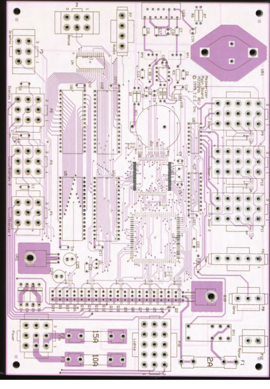
ELECTRICAL / ELECTRONIC REPAIR
MAIN P.C. BOARD
1. Turn off all A.C. power and remove the power cord
from the A.C. receptacle.
2. Remove the WACKY DUCKS™ sign from the front
of the game.
3. Remove all of the P.C. Board connectors, noting
where each one connects onto the board.
4. Remove the 4 hex fasteners that connect the board to
the cabinet.
5. Re-assemble in reverse order.
FROG DISPLAY BOARD
1. Remove the cover glass retainer by removing the 4
Allen head screws, and remove the cover glass.
2. Unplug the frog display board.
3. Remove the 3 screws that hold the P.C. Board to
the frog display.
4. Re-assemble in the reverse order.
MAINTENANCE
Maintenance is easy, as the game requires very little
service under normal use. For your customers to get
the greatest enjoyment from the game, please per-
form the following periodically:
• Clean the cabinet with soapy water or a commer-
cial cleaner such as Fantastik™ or Formula
409™. Do not use any chemicals such as alco-
hol, benzene, or paint thinners that could dam-
age the finish. Finish cleaning the cabinet by ap-
plying a good quality spray furniture polish.
• Clean the glass with a good quality glass
cleaner.
• Adjust the Duck Belt to assure proper tracking
and operation.
• Clean the coin mechs with a soapy water solu-
tion to remove dirt and grime.
• Clean the push buttons if they become sticky in
use.
• Clean dirt and grime from the punching mecha-
nisms if they become sluggish.
NOTE: DO NOT USE ANY LUBRICANT ON THE
PUNCHING MECHANISMS, AS THIS WILL ONLY
ATTRACT DIRT, WHICH WILL BIND, AND SLOW
THE UNITS. If the punching mechanisms still re-
spond sluggishly after cleaning, check you’re A.C.
line voltage to be sure it matches the way your game
is set.
IF YOU HAVE ANY QUESTIONS REGARDING
THE PROGRAMMING OPTIONS, PLEASE CON-
TACT OUR SERVICE DEPARTMENT
PHONE: 1-716-759-0360
FAX: 1-716-759-0884
E-MAIL: service@icegame.com

22
PARTS LISTING
MECHANICAL PARTS
FP1019 LEVELER FOOT
HD1052 SWIVEL CASTER
WA5001 TRIPLE COIN DOOR
WK1001 CONTROL BOX
WK1014 RAMP (DUCK LIFT)
WK1020 PUNCH ASSEMBLY BRACKET
WK1022 SPRING PLUNGER LINK
WK1023 SCISSOR PIN
WK1025 COIL RETAINER BRACKET
WK1026 HINGE WASHER, SQUARE
WK1050 BEARING, CONVEYOR ROLLER
WK1051 HINGE, DUCK TARGET
WK1052 PLUNGER SPRING
WK3005X CONVEYOR ROLLER W / GRIT
WK3010 PLUNGER LINK BLOCK 1 ½ SQ.
WK3011 PLUNGER LINK #1
WK3012 PLUNGER LINK #2
WK3013 PLUNGER LINK #3
WK3014 PLUNGER LINK #4
WK3015 PLUNGER LINK, END
WK3016 PUNCHING GLOVE
WK3020 DUCK, SMALL BABY
WK3021 DUCK, LARGE MAMA
WK4001X CONVEYOR BELT ASSEMBLY
WK9001 SERVICE MANUAL
GRAPHICS & DECALS
7031 FOR INDOOR USE ONLY DECAL
7033 WARNING, POWER DIS DECAL
7047 WARNING, VHO BULB ONLY
WK7000 OUTSIDE LEFT CABINET DECAL
WK7001 OUTSIDE RIGHT CABINET DECAL
WK7002 CABINET INSIDE LEFT DECAL
WK7003 CABINET INSIDE RIGHT DECAL
WK7004 FROG DECAL
WK7005 POND DECAL
WK7007 REAR BACKDROP DECAL
WK7008 DUCK DISPLAY DECAL
WK7009 EYEBALL DECAL
WK7010 LOWER CABINET FRONT DECAL
WK7012 LEFT CONTROL PANEL
WK7013 INSTRUCTION DECAL (TIME)
WK7014 RIGHT CONTROL PANEL
WK7021 PROGRAMMING DECAL
WK7023 INSTRUCTION DECAL (TICKET)
WK7024 FROG "TICKET" DECAL
WK7025 CLOUD
WK7026 RAINBOW MARQUEE BACKGROUND
WK7028 FRONT HEADER SIGN
WK7029 DUCK MARQUEE DECAL
ELECTRICAL / ELECTRONIC
PARTS
211 LOW TICKET SWITCH
2005 LIGHT BULB, #906
2026 THERMAL SWITCH
2133CW ROPE LIGHT, CHASING 110 VOLT
2364X FAN ASSEMBLY
HH5005 TICKET DISPENSER
PC20224 12-VOLT COUNTER
PC20238 BULB SOCKET, TWIST
PC20239 LIGHT BULB, #161
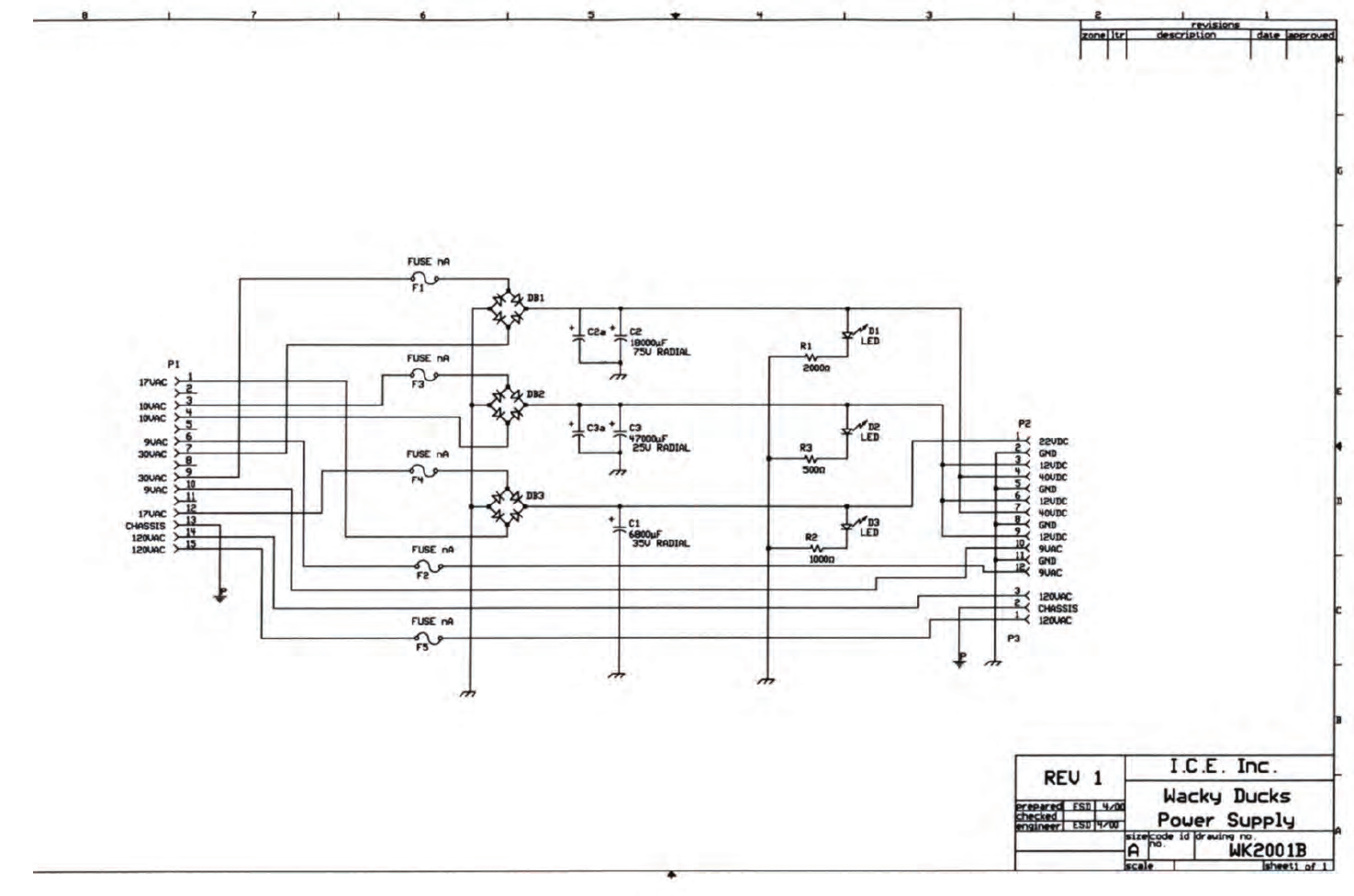
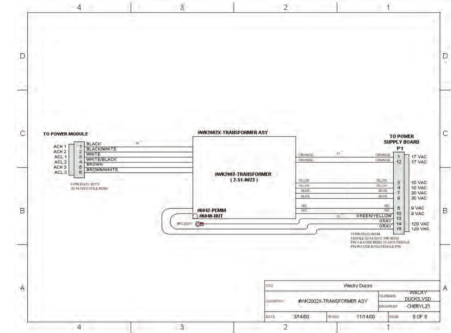
WK2001X POWER SUPPLY
WK2002X TRANSFORMER
WK2007X POWER MODULE
WK2008 DRIVE MOTOR
WK2009 COIL, INCLUDES SLEEVE
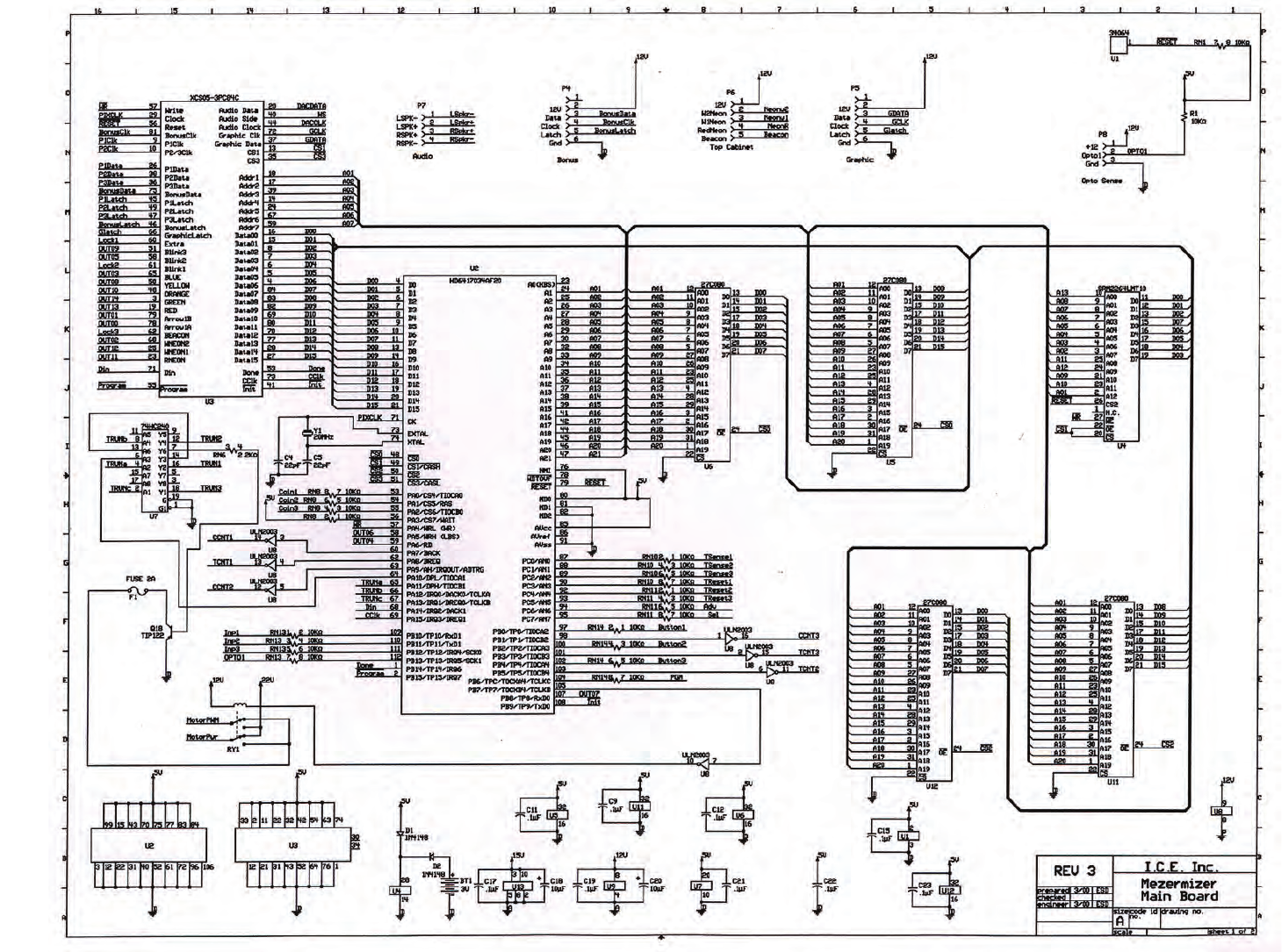
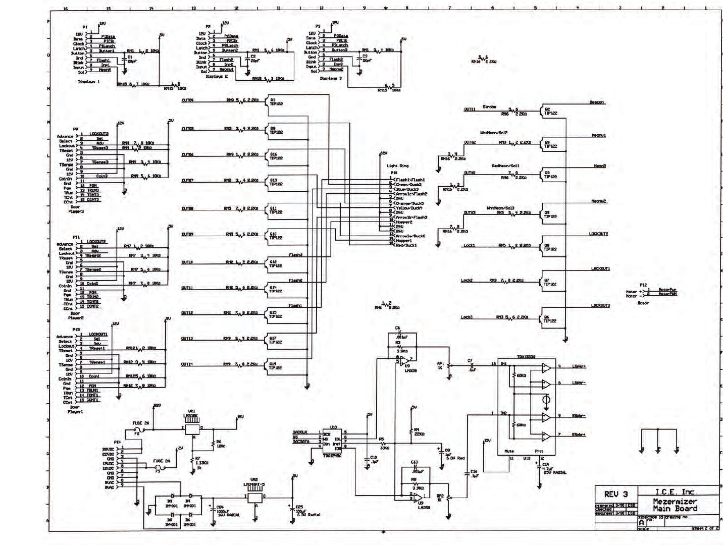
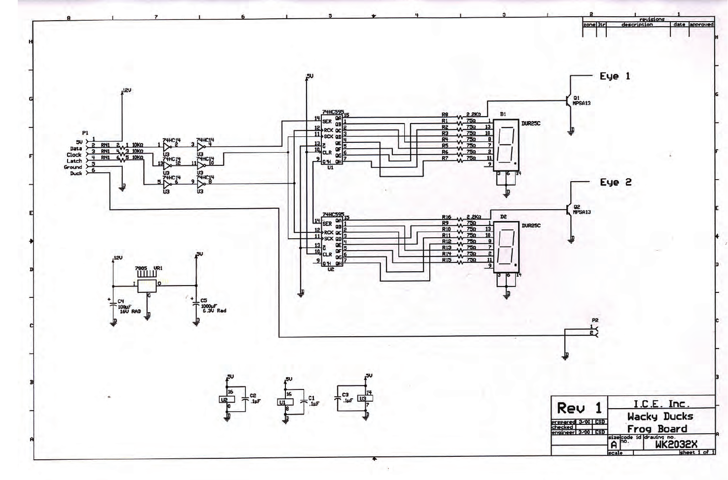
WK2032X DISPLAY P.C. BOARD ASSEMBLY
WK2034X MAIN P.C. BOARD ASSEMBLY
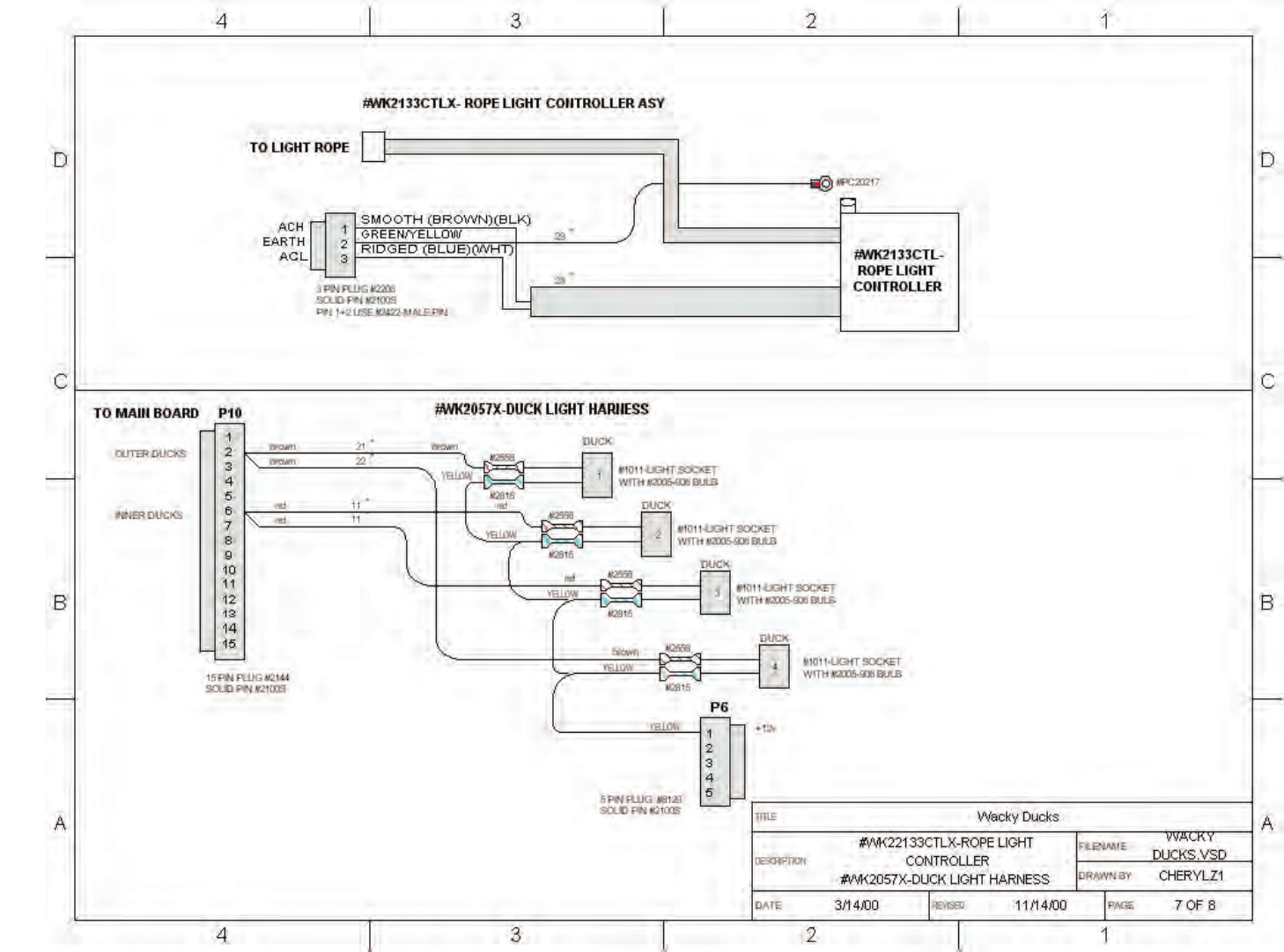
WK2133CTLX ROPE LIGHT CONTROLLER
WK8284X BALLAST ASSEMBLY
23
24
25
26
27
28
29
30
31
32
33
D
C
B
A
4321
D
C
B
A
4321
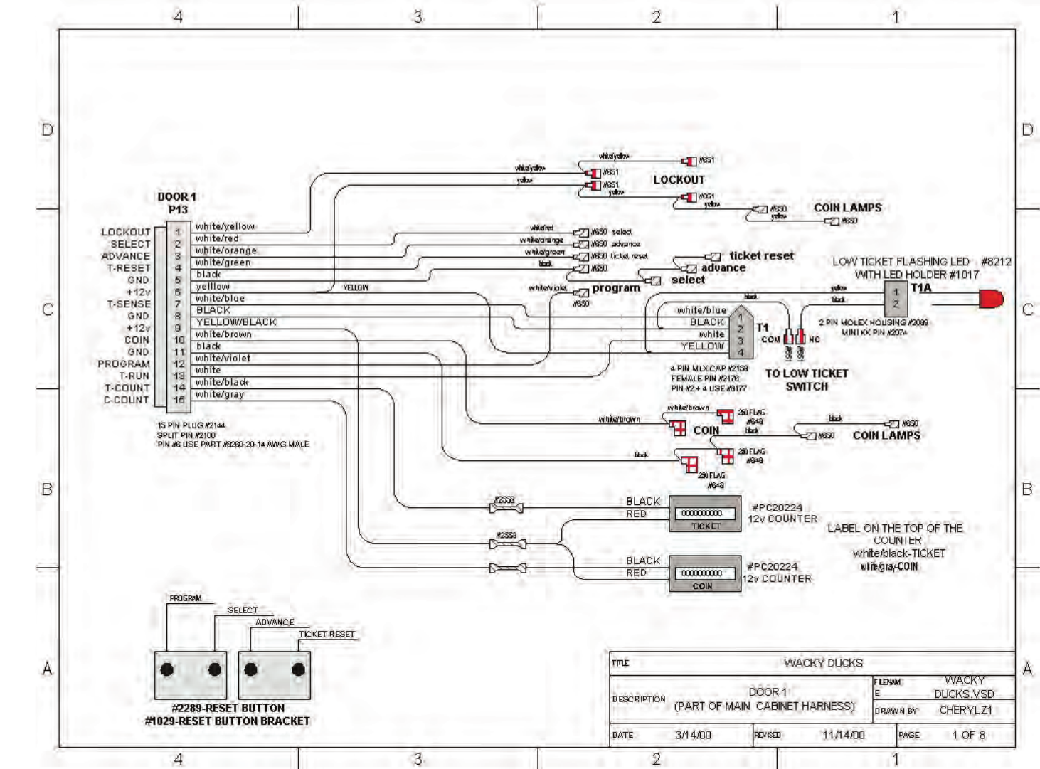
DATE 3/14/00
DESCRIPTION
DRAWN BY CHERYLZ1
FILENAME WACKY
DUCKS.VSD
PAGE 6 OF 8
REVISED 6/14/01
TITL
EWacky Ducks
1
2
3
3 PIN PLUG #2206
Pin 2: SOLID PIN #2100S
Pins 1+3: 20-14 AWG #8260
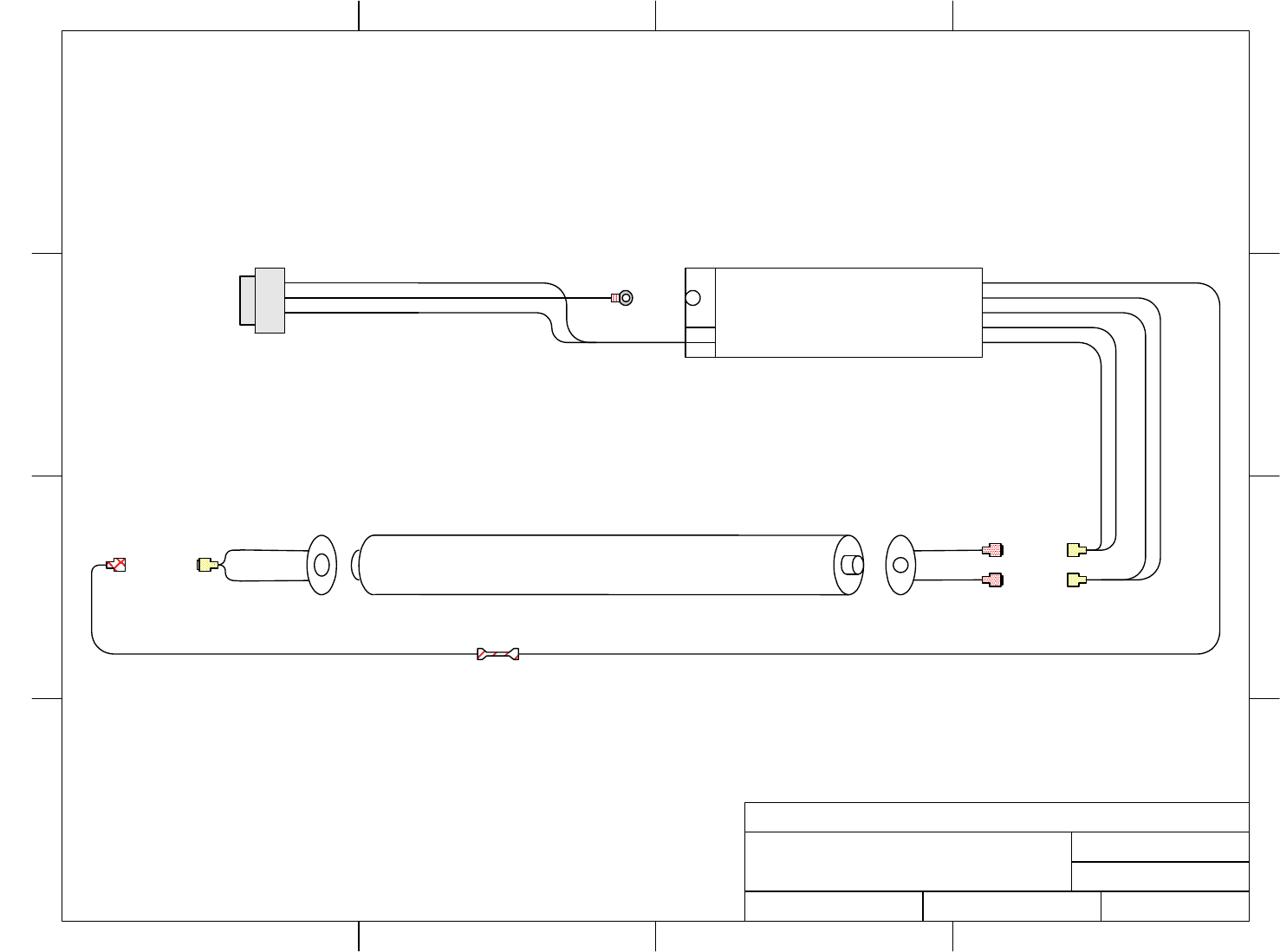
#8284 - WORKHORSE 120V
#WH6-120-6
BALLAST
#PC20217
BLACK
GREEN/YELLOW
WHITE
TO MAIN HARNESS
#8280-FLOURESCENT BULB ( F48T12VHO ) M .250 #654
M .250 #654
W / SPRING .#8252-
FEMALE
.250 #653T
M
#8282-
MALE
#WK8239X-
SOCKET ASY
#2558"
18YELLOW
"
18
"
36
"
11 1/2
#WK8284X-BALLAST ASY
#WK8239X- SOCKET ASY
#SR8239SX-SOCKET ASY
W/SPRING
YELLOW
RED
RED
RED
RED
ACH
GRND
ACL
34
35
Contacts at SEGA
Machine Sales
Telephone: +44 (0) 208 391 8090
Fax: +44 (0) 208 391 8099
www.sega-amusements.co.uk
SEGA Spares
Telephone: +44 (0) 208 391 8060
Fax: +44 (0) 208 391 8096
www.segatotalsolutions.com
Customer Services
Telephone: +44 (0) 208 391 8065
Fax: +44 (0) 208 391 8096
