Arcade Wild Riders Manual Cover User
Wild Riders STD Wild Riders STD
wildRidersSTD wildRidersSTD
WILD RIDERS STANDARD WITHOUT WIRING DIAGRAMS WildRidersSTD SAUService.com - WildRiders
2013-11-28
User Manual: Arcade Wild Riders Manual
Open the PDF directly: View PDF ![]() .
.
Page Count: 105 [warning: Documents this large are best viewed by clicking the View PDF Link!]

1ST PRINTING FEB. 01
MANUAL NO. 999-1149
Owner’s ManualOwner’s Manual
Owner’s ManualOwner’s Manual
Owner’s Manual
SEGA ENTERPRISES, INC. USA
STD TYPE

Warranty
Your new Sega Product is covered for a period of 90 days from the date of shipment. This certifies
that the Printed Circuit Boards, Power Supplies and Monitor are to be free of defects in workman-
ship or materials under normal operating conditions. This also certifies that all Interactive Control
Assemblies are to be free from defects in workmanship and materials under normal operating condi-
tions. No other product in this machine is hereby covered.
Sellers sole liability in the event a warranted part described above fails shall be, at its option, to
replace or repair the defective part during the warranty period. For Warranty claims, contact your
Sega Distributor.
Should the Seller determine, by inspection that the product was caused by Accident, Misuse, Ne-
glect, Alteration, Improper Repair, Installation or Testing, the warranty offered will be null and void.
Under no circumstances is the Seller responsible for any loss of profits, loss of use, or other dam-
ages.
This shall be the exclusive written Warranty of the original purchaser expressed in lieu of all other
warranties expressed or implied. Under no circumstance shall it extend beyond the period of time
listed above.

BEFORE USING THE PRODUCT, BE SURE TO READ THE FOLLOWING:
To maintain the safety:
To ensure the safe usage of the product, be sure to read the following before using the product. The following
instructions are intended for the users, operators and the personnel in charge of the operation of the product.
After carefully reading and sufficiently understanding the warning displays and cautions, handle the product
appropriately. Be sure to keep this manual nearby the product or elsewhere convenient for referring to it
when necessary.
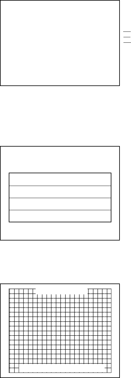
Herein, explanations which require special attention are enclosed with dual lines. Depending on the poten-
tially hazardous degrees, the terms of WARNING, CAUTION, etc. are used. Be sure to understand the
contents of the displays before reading the text.
Indicates that mishandling the
product by disregarding this
warning will cause a potentially
hazardous situation which can
result in death or serious injury.
Indicates that mishandling the product
by disregarding this caution will cause
a slight hazardous situation which can
result in personal injury and or material
damage.
For the sage usage of the product, the following pictographs are used:
Indicates “HANDLE WITH CARE.” In order to protect the human body an equipment, this
display is attached to places where the Owner’s Manual and or Service Manual should be referred
to.
Perform work in accordance with the instructions herein stated.
Instructions for work are explained by paying attention to the aspect of accident prevention. Failing to
perform work as per the instructions can cause accidents. In the case where only those who have techni-
cal expertise should perform the work to avoid hazardous situation, the instructions herein state that the
serviceman should perform such work.
Be sure to turn off power before working on the machine.
To prevent electric shock, be sure to turn off power before starting the work in which the worker touches
the interior of the product. If the work is to be performed in the power-on status, the Instruction Manual
herein always states to that effect.
Be sure to ground the Earth Terminal (this, however, is not required in the case where a power cord
with earth is used).
This product is equipped with the Earth Terminal. When installing the product, Connect the Earth Termi-
nal to the “accurately grounded indoor earth terminal” by using an earth wire. Unless the product is
grounded appropriately, the user can be subject to electric shock. After performing repair, etc. for the
Control equipment, ensure that the Earth Wire is firmly connected to the Control equipment.
Ensure that the Power Supply used is equipped with an Earth Leakage Breaker.
This product does not incorporate the Earth Leakage Breaker. Using a power supply which is not
equipped with the Earth Leakage Breaker can cause a fire when earth leakage occurs.
Be sure to use fuses which meet the specified rating. (only for the machines which use fuses).
Using fuses exceeding the specified rating can cause a fire and electric shock.

Specification changes (removal of equipment, conversion and addition) not designated by SEGA
are not allowed.
The parts of the product include warning labels for safety, covers for personal protection, etc. It is very
hazardous to operate the product by removing parts and or modifying the circuits. Should doors, lids
and protective parts be damaged or lost, refrain from operating the product, and contact where the
product was purchased from or the office herein stated. SEGA shall not be held responsible for any
accidents, compensation for damage to a third party, resulting from the specifications not designated by
SEGA.
Ensure that the product meets the requirements of appropriate Electrical Specifications.
Before installing the product, check for Electrical Specifications. SEGA products have a nameplate on
which Electrical Specifications are described. Ensure that the product is compatible with the power
supply voltage and frequency requirements of the location. Using any Electrical Specifications different
from the designated Specifications can cause a fire and electric shock.
Install and operate the product in places where appropriate lighting is available, allowing warning
labels to be clearly read.
To ensure safety for the customers, labels and printed instructions describing potentially hazardous
situation are applied to places where accidents can be caused. Ensure that where the product is operated
has sufficient lighting allowing the warnings to be read. If any label is peeled off, apply it again imme-
diately. Please place an order with where the product was purchased from or the office herein stated.
When handling the Monitor, be very careful. (Applies only to the product w/monitor.)
Some of the monitor (TV) parts are subject to high tension voltage. Even after running off power, some
portions are still subject to high tension voltage sometimes. Monitor repair and replacement should be
performed only be those technical personnel who have knowledge of electricity and technical expertise.
Be sure to adjust the monitor (projector) properly. (Applies only to the product w/monitor.)
Do not operate the product leaving on-screen flickering or blurring as it is. Using the product with the
monitor not properly adjusted may cause dizziness or a headache to an operator, a player, or the custom-
ers.
When transporting or reselling this product, be sure to attach this manual to the product.
In the case where commercially available monitors and printers are used in this product, only the
contents relating to this product are explained herein. Some commercially available equipment has
functions and reactions not stated in this manual. Read this manual together with the specific Instruc-
tion Manual of such equipment.
Descriptions herein contained may be subject to improvement changes without notice.
The contents described herein are fully prepared with due care. However, should any question arise or
errors be found, please contact SEGA.
•
•
INSPECTIONS IMMEDIATELY AFTER TRANSPORTING THE PRODUCT TO THE LOCATION.
Normally, at the time of shipment, SEGA products are in a status allowing for usage immediately after
transporting to the location. Nevertheless, an irregular situation may occur during transportation. Before
turning on power, check the following points to ensure that the product has been transported in a satisfac-
tory status.
Are there any dented portions or defects (cuts, etc.) on the external surfaces of the cabinet?
Are Casters and Adjusters, damaged?
Do the power supply voltage and frequency requirements meet with those of the location?
Are all wiring connectors correctly and securely connected? Unless connected in the correct direction,
connector connections can not be made accurately. Do not insert connectors forcibly.
Do power cords have cuts and dents?
Do the fuses used meet specified rating? Is the Circuit Protector in an energized status?
Are all accessories available?
Can all Doors and Lids be opened with the Accessory keys? Can Doors and Lids be firmly closed?

TABLE OF CONTENTS
BEFORE USING THE PRODUCT, BE SURE TO READ THE FOLLOWING:
TABLE OF CONTENTS
INTRODUCTION OF THE OWNER’S MANUAL
1. HANDLING PRECAUTIONS ..........................................................................................
2. PRECAUTIONS CONCERNING INSTALLATION LOCATION ...................................
3. OPERATION .....................................................................................................................
4. ACCESSORIES .................................................................................................................
5. ASSEMBLING AND INSTALLATION ............................................................................
6. PRECAUTIONS TO BE HEEDED WHEN MOVING THE MACHINE ........................
7. CONTENTS OF GAME ....................................................................................................
8. EXPLANATION OF TEST AND DATA DISPLAY .........................................................
8 - 1 SWITCH UNIT AND COIN METER ............................................................
8 - 2 SYSTEM TEST MODE ..................................................................................
8 - 3 GAME TEST MODE ......................................................................................
9. CONTROL PANEL .............................................................................................................
9 - 1 ADJUSTING/REPLACING THE HANDLBAR VOLUME ...........................
9 - 2 ADJUSTING/REPLACING THE ACCELERATOR VOLUME .....................
9 - 3 REPLACING THE CONTROL STICK’S MICROSWITCH ..........................
9 - 4 GREASING ......................................................................................................
9 - 5 REPLACING THE SPRING ............................................................................
10. REAR BRAKE..................................................................................................................
10 - 1 REMOVING THE BRAKE UNIT .................................................................
10 - 2 ADJUSTING/REPLACING THE REAR BRAKE VOLUME ......................
10 - 3 GREASING ....................................................................................................
11. MONITOR ........................................................................................................................
11 - 1 CAUTIONS AND WARNINGS CONCERNING THE SAFETY FOR
HANDLING THE MONITORS .....................................................................
11 -2 CAUTIONS TO BE HEEDED WHEN CLEANING THE CRT
SURFACES ....................................................................................................
12. COIN SELECTOR ............................................................................................................
13. PERIODIC INSPECTION TABLE ..................................................................................
14. TROUBLESHOOTING ....................................................................................................
15. GAME BOARD ................................................................................................................
15 - 1 TAKING OUT THE GAME BOARD ...........................................................
15 - 2 COMPOSITION OF GAME BOARD ...........................................................
15 - 3 REPAIR/SERVICING AND CARTON BOX ...............................................
16. DESIGN RELATED PARTS ............................................................................................
17. PARTS LIST .....................................................................................................................
18. WIRE COLOR CODE TABLE .........................................................................................
19. WIRING DIAGRAM ........................................................................................................
1 -2
3 - 4
5 - 7
8
9 - 15
16
17 - 20
21 - 43
22
23 - 35
36 - 43
44 - 54
45 - 47
48
49
50 - 53
54
55 - 58
55 - 56
56
57 - 58
59 - 61
59 - 61
61
62 - 66
67
68 - 71
72 - 76
72 - 73
74
75 - 76
77
78 - 95
96
97 - 98

SPECIFICATIONS
INTRODUCTION OF THE OWNERS MANUAL
This Owner's Manual is intended to provide detailed descriptions together with all
the necessary information covering the general operation of electronic assemblies,
electromechanicals, servicing control, spare parts, etc. as regards the product,
WILD RIDER STD TYPE.
This manual is intended for the owners, personnel and managers in charge of
operation of the product. Operate the product after carefully reading and sufficiently
understanding the instructions. If the product fails to function satisfactorily, non-
technical personnel should under no circumstances touch the internal system. Please
contact where the product was purchased from.
SEGA ENTERPRISES, INC. (U.S.A.)/CUSTOMER SERVICE
45133 Industrial Drive, Fremont, California 94538, U.S.A.
Phone : (415) 701-6580
Fax : (415) 701-6594
Use of this product is unlikely to cause physical injuries or damages to property. However,
where special attention is required this is indicated by a thick line, the word "IMPORTANT"
and its sign in this manual.
Indicates that mishandling the product by disregarding this display can cause the
product's intrinsic performance not to be obtained, resulting in malfunctioning.
STOP
IMPORTANT
Length : 74 inches
Height : 65 inches.
Width : 31 inches
Weight : Approx. 400 lbs.
MONITOR : 29 INCH COLOR MONITOR
DEFINITION OF LOCATION MAINTENANCE MAN AND SERVICEMAN
Non-technical personnel who do not have technical knowledge and expertise should
refrain from performing such work that this manual requires the location's
maintenance man or a serviceman to carry out, or work which is not explained in
this manual. Failing to comply with this instruction can cause a severe accident
such as electric shock.
Ensure that parts replacement, servicing & inspections, and troubleshooting are performed by the
location's maintenance man or the serviceman. It is instructed herein that particularly hazardous
work should be performed by the serviceman who has technical expertise and knowledge.
The location's maintenance man and serviceman are herein defined as follows:
"Location's Maintenance Man" :
Those who have experience in the maintenance of amusement equipment and vending machines,
etc., and also participate in the servicing and control of the equipment through such routine work
as equipment assembly and installation, servicing and inspections, replacement of units and
consumables, etc. within the Amusement Facilities and or locations under the management of the
Owner and Owner's Operators of the product.
Activities of Location's Maintenance Man :
Assembly & installation, servicing & inspections, and replacement of units & consumables as
regards amusement equipment, vending machines, etc.
Serviceman :
Those who participate in the designing, manufacturing, inspections and maintenance service of
the equipment at an amusement equipment manufacturer.
Those who have technical expertise equivalent to that of technical high school graduates as re-
gards electricity, electronics and or mechanical engineering, and daily take part in the servicing &
control and repair of amusement equipment.
Serviceman's Activities :
Assembly & installation and repair & adjustments of electrical, electronic and mechanical parts of
amusement equipment and vending machines.
LISTED
UL
®
5K92
AMUSEMENT MACHINE
1
1. HANDLING PRECAUTIONS
When installing or inspecting the machine, be very careful of the following points and pay
attention to ensure that the player can enjoy the game safely.
Non-compliance with the following points or inappropriate handling running counter to the
cautionary matters herein stated can cause personal injury or damage to the machine.
Before performing work, be sure to turn power off. Performing the work
without turning power off can cause an electric shock or short circuit. In the
case work should be performed in the status of power on, this manual always
states to that effect.
To avoid electric shock or short circuit, do not plug in or unplug quickly.
To avoid electric shock, do not plug in or unplug with a wet hand.
Do not expose Power Cords and Earth Wires on the surface, (floor, passage,
etc.). If exposed, the Power Cords and Earth Wires are susceptible to damage.
Damaged cords and wires can cause electric shock or short circuit.
To avoid causing a fire or electric shock, do not put things on or damage
Power Cords.
When or after installing the product, do not unnecessarily pull the power cord.
If damaged, the power cord can cause a fire or electric shock.
In case the power cord is damaged, ask for replacement through where the
product was purchased from or the office herein stated. Using the cord as is
damaged can cause fire, electric shock or leakage.
Be sure to perform grounding appropriately. Inappropriate grounding can
cause an electric shock.
Be sure to use fuses meeting specified rating. Using fuses exceeding the
specified rating can cause a fire or electric shock.
Completely make connector connections for IC BD and others. Insufficient
insertion can cause an electric shock.
Specification changes, removal of equipment, conversion and/or addition, not
designated by SEGA are not permitted.
• Failure to observe this may cause a fire or an electric shock. Non-compliance
with this instruction can have a bad influence upon physical conditions of the
players or the lookers-on, or result in injury during play.
• SEGA shall not be held responsible for damage, compensation for damage to
a third party, caused by specification changes not designated by SEGA.
Be sure to perform periodic maintenance inspections herein stated.

2
For the IC board circuit inspections, only the logic tester is allowed. The use
of a multiple-purpose tester is not permitted, so be careful in this regard.
When cleaning the CRT surfaces, use a soft, dry cloth. Do not apply
chemicals such as thinner, benzine, etc.
The electronic parts on the IC Board could be damaged due to human body's
static electricity. Before performing IC Board related work, be sure to
discharge physically accumulated statics by touching grounded metallic
surfaces, etc.
Some parts are the ones designed and manufactured not specifically for this
game machine. The manufacturers may discontinue, or change the
specifications of, such general-purpose parts. If this is the case, Sega cannot
repair or replace a failed game machine whether or not a warranty period has
expired.
STOP
IMPORTANT
3
2. PRECAUTIONS CONCERNING INSTALLATION
LOCATION
This product is an indoor game machine. Do not install it outside. Even indoors,
avoid installing in places mentioned below so as not to cause a fire, electric shock,
injury and or malfunctioning.
Places subject to rain or water leakage, or places subject to high humidity in
the proximity of an indoor swimming pool and or shower, etc.
Places subject to direct sunlight, or places subject to high temperatures in the
proximity of heating units, etc.
Places filled with inflammable gas or vicinity of highly inflammable/volatile
chemicals or hazardous matter.
Dusty places.
Sloped surfaces.
Places subject to any type of violent impact.
Vicinity of anti-disaster facilities such as fire exits and fire extinguishers.
The operating (ambient) temperature range is from 5 Celsius to 40 Celsius.
Only in the case a projector is employed, the temperature range is from 5
Celsius to 30 Celsius.
LIMITATIONS OF USAGE REQUIREMENTS
Be sure to check the Electrical Specifications.
Ensure that this product is compatible with the location's power supply,
voltage and frequency requirements.
A plate describing Electrical Specifications is attached to the product.
Non-compliance with the Electrical Specifications can cause a fire and
electric shock.
This product requires the Breaker and Earth Mechanisms as part of the
location facilities. Using them in a manner not independent can cause a fire
and electric shock.
Ensure that the indoor wiring for the power supply is rated at 7A or higher
(AC single phase 100 ~ 120V area), and 4A or higher (AC 220 ~ 240V area).
Non-compliance with the Electrical Specifications can cause a fire and
electric shock.
Be sure to independently use the power supply equipped with the Earth
Leakage Breaker. Using a power supply without the Earth Leakage Breaker
can cause an outbreak of fire when earth leakage occurs.
Putting many loads on one electrical outlet can cause generation of heat and a
fire resulting from overload.
When using an extension cord, ensure that the cord is rated at 7A or higher
(AC 100 ~ 120V area) and 4A or higher (AC 220 ~ 240V area). Using a cord
rated lower than the specified rating can cause a fire and electric shock.
4
Electric current consumption
MAX. 3.66 A (AC 110V 50 Hz)
MAX. 3.57 A (AC 110V 60 Hz)
MAX. 3.25 A (AC 120V 60 Hz)
MAX. 1.83 A (AC 220V 50 Hz)
MAX. 1.82 A (AC 220V 60 Hz)
MAX. 1.77 A (AC 230V 50 Hz)
MAX. 1.73 A (AC 230V 60 Hz)
MAX. 1.70 A (AC 240V 50 Hz)
MAX. 1.68 A (AC 240V 60 Hz)
MAX. 3.70 A (For TAIWAN)
STOP
IMPORTANT
For transporting the machine into the location's building, the minimum necessary
dimensions of the opening (of doors, etc.) are 0.8m(W) and 1.8m(H).
For the operation of this machine, secure a minimum area of 1.3m (W) X
1.6m (D). In order to prevent injury resulting from the falling down accident
during game play, be sure to secure the minimum area for operation.
Be sure to provide sufficient space so as to allow this product's ventilation fan
to function efficiently. To avoid machine malfunctioning and a fire, do not
place any obstacles near the ventilation opening.
SEGA shall not be held responsible for damage, compensation for damage to
a third party, resulting from the failure to observe this instruction.
OPERATION AREA
5
3. OPERATION
PRECAUTIONS TO BE HEEDED BEFORE STARTING THE OPERATION
To avoid injury and trouble, be sure to constantly give careful attention to the behavior and
manner of the visitors and players.
In order to avoid accidents, check the following before starting the operation:
To ensure maximum safety for the players and the customers, ensure that
where the product is operated has sufficient lighting to allow any warnings to
be read. Operation under insufficient lighting can cause bodily contact with
each other, hitting accident, and or trouble between customers.
Be sure to perform appropriate adjustment of the monitor (projector). For
operation of this machine, do not leave monitor's flickering or deviation as is.
Failure to observe this can have a bad influence upon the players' or the
customers' physical conditions.
It is suggested to ensure a space allowing the players who feel sick while
playing the game to take a rest.
Check if all of the adjusters are in contact with the surface. If they are not, the
Cabinet can move and cause an accident.
6
Do not put any heavy item on this product. Placing any heavy item on the
product can cause a falling down accident or parts damage.
Do not climb on the product. Climbing on the product can cause falling down
accidents. To check the top portion of the product, use a step.
To avoid electric shock, check to see if door & cover parts are damaged or
omitted.
To avoid electric shock, short circuit and or parts damage, do not put the
following items on or in the periphery of the product.
Flower vases, flowerpots, cups, water tanks, cosmetics, and receptacles/
containers/vessels containing chemicals and water.
To avoid injury, be sure to provide sufficient space by considering the potentially
crowded situation at the installation location. Insufficient installation space can
cause making bodily contact with each other, hitting accidents, and or trouble
between customers.
To avoid injury and trouble, be sure to constantly give careful attention to the behavior and
manner of the visitors and players.
PRECAUTIONS TO BE HEEDED DURING OPERATION (PAYING ATTENTION TO CUSTOMERS)
To avoid injury and accidents, those who fall under the following categories
are not allowed to play the game.
•Those who need assistance such as the use of an apparatus when walking.
•Those who have high blood pressure or a heart problem.
•Those who have experienced muscle convulsion or loss of consciousness when
playing video game, etc.
•Those who have a trouble in the neck and or spinal cord.
•Intoxicated persons.
•Pregnant women or those who are in the likelihood of pregnancy.
•Persons susceptible to motion sickness.
•Persons whose act runs counter to the product's warning displays.
A player who has never been adversely affected by light stimulus might
experience dizziness or headache depending on his physical condition when
playing the game. Especially, small children can be subject to those
conditions. Caution guardians of small children to keep watch on their
children during play.
Instruct those who feel sick during play to have a medical examination.
To avoid injury resulting from falling down and electric shock due to spilled
drinks, instruct the player not to place heavy items or drinks on the product.
To avoid electric shock and short circuit, do not allow customers to put hands
and fingers or extraneous matter in the openings of the product or small
openings in or around the doors.
To avoid falling down and injury resulting from falling down, immediately
stop the customer's leaning against or climbing on the product, etc.
7
Immediately stop such violent acts as hitting and kicking the product. Such
violent acts can cause parts damage or falling down, resulting in injury due to
fragments and falling down.
To avoid electric shock and short circuit, do not allow the customers to
unplug the power plug without a justifiable reason.
Caution lookers-on so as not to touch the operating unit while in play. Failure
to observe this may cause bodily contact with the player and trouble between
the customers.
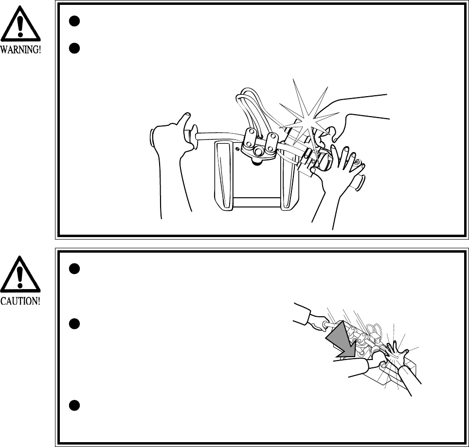
Persons other than the player must
not touch the device during play. If
this is violated, their hands or fingers
may be pinched by the handlebar,
causing them to be injured.
Instruct the player to watch his/her
step when getting on the Floor Base
so as to avoid stumbling over.
8
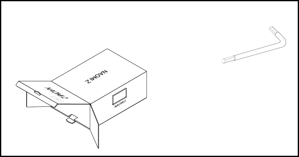
4. ACCESSORIES
When transporting the machine, make sure that the following parts are supplied.
TABLE 4 ACCESSORIES
CARTON BOX
601-11044 (1)
Used for transporting the Game Board.
Refer to 15-3.
TAMPERPROO WRENCH
M4 540-0006-01 (1)
M6 540-0015-01 (1)
TOOL
9
Perform assembly work by following the procedure herein stated. Failing to
comply with the instructions can cause electric shock hazard.
Perform assembling as per this manual. Since this is a complex machine,
erroneous assembling can cause an electric shock, machine damage and or not
functioning as per specified performance.
When assembling, be sure to use plural persons. Depending on the assembly
work, there are some cases in which working by one person alone can cause
personal injury or parts damage.
Ensure that connectors are accurately connected. Incomplete connections can
cause electric shock hazard.
Be careful so as not to damage wirings. Damaged wiring can cause electric
shock and short circuit hazards.
This work should be performed by the Location's Maintenance Man or
Serviceman. Performing work by non-technical personnel can cause a severe
accident such as electric shock. Failing to comply with this instruction can
cause a severe accident such as electric shock to the player during operation.
Provide sufficient space so that assembling can be performed. Performing
work in places with narrow space or low ceiling may cause an accident and
assembly work to be difficult.
To perform work safely and avoid serious accident such as the cabinet's
falling down, do not perform work in places where step-like grade
differences, a ditch, or slope exist.
When handling plastic parts, use care. Do not give a shock or apply excessive
load to the fluorescent lamps and plastic parts. Failure to observe this can
cause parts damage, resulting in injury due to fragments, cracks and broken
pieces.
To perform work safely and securely, be sure to prepare a step which is in a
secure and stable condition. Performing work without using the step can
cause violent falling down accidents.
5. ASSEMBLING AND INSTALLATION

10
When carrying out the assembling and installation, follow the following 5-item sequence.
SECURING IN PLACE (ADJUSTER ADJUSTMENT)
REMOVING THE SHIPPING BRACKET
POWER SUPPLY, AND EARTH CONNECTION
TURNING POWER ON
ASSEMBLY CHECK
1
2
3
4
5
11
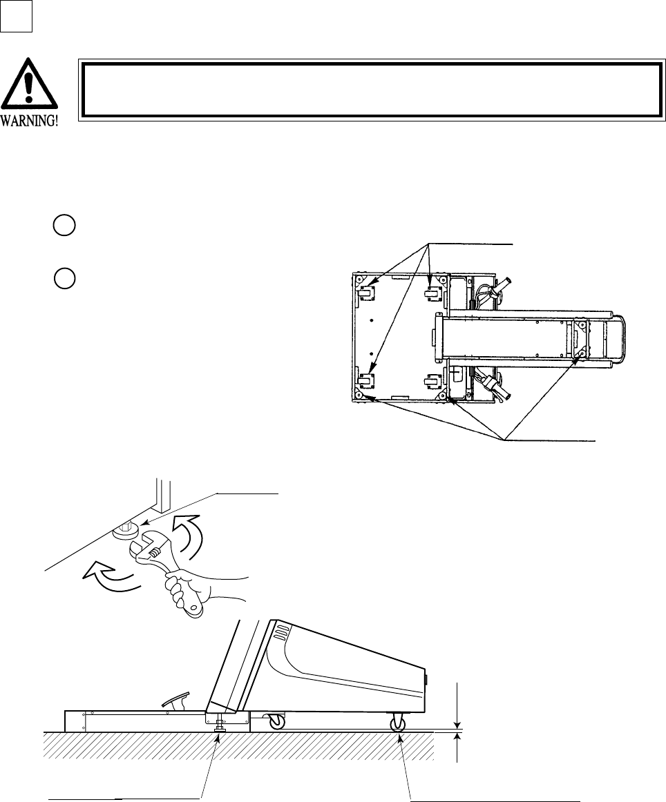
Move the product to the
installation position.
Let the Adjusters make contact
with the floor. Adjust the height of
the 2 Adjusters by using a wrench
to ensure the product position is
level. If the floor surfaces are
level, the product will be level
when the front casters are raised
approximately 7mm above the
floor.
Make sure that all of the adjusters are in contact with the floor. If they are not, the
cabinet can move and cause an accident.
SECURING IN PLACE (ADJUSTER ADJUSTMENT)
This product has 2 Adjusters at the bottom front part of cabinet and 4 Casters in the rear. When
the installation position is determined, let the Adjusters make direct contact with the floor and
adjust to ensure the product position is level.
FIG. 5. 4 a BOTTOM VIEW
ADJUSTER
Have adjusters make contact
with the floor.
FIG. 5. 4 b ADJUSTER
Approx.7mm
Ensure that the 2 Rear Casters are
in contact with the surface (floor).
1
2
1
CASTERS
ADJUSTERS
12
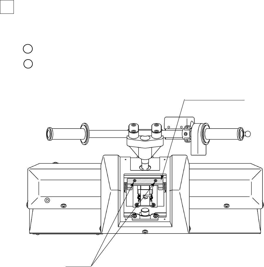
REMOVING THE SHIPPING BRACKET
The mechanism of equipment is fastened for transportation at shipping. Remove the shipping
bracket and screws.
Remove the front lid (see Section 9-1).
Take out the 2 screws and remove the shipping braket. (FIG. 5. 5)
FIG. 5. 5
MECHA SHIPPING BRKT
WRD-0003
SCREW (2)
M4 X 8, w/flat & spring washers
1
2
2
13
Be sure to independently use the power supply socket outlet equipped with an
Earth Leakage Breaker. Using a power supply without an Earth Leakage
Breaker can cause a fire when electric leakage occurs.
Ensure that the "accurately grounded indoor earth terminal" and the earth wire
cable are available (except in the case where a power cord plug with earth is
used). This product is equipped with the earth terminal. Connect the earth
terminal and the indoor earth terminal with the prepared cable. If the
grounding work is not performed appropriately, customers can be subjected to
an electric shock, and the product's functioning may not be stable.
Ensure that the power cord and earth wire are not exposed on the surface
(passage, etc.). If exposed, they can be caught and are susceptible to damage.
If damaged, the cord and wire can cause electric shock and short circuit
accidents. Ensure that the wiring position is not in the customer's passage
way or the wiring has protective covering.
After wiring power cord on the floor, be sure to protect the power cord.
Exposed power cord is susceptible to damage and causes an electric shock
accident.
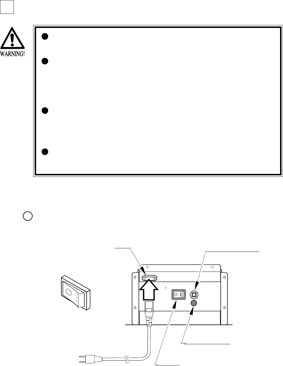
POWER SUPPLY, AND EARTH CONNECTION
The AC Unit is mounted on the rear of the machine. The AC Unit has Main SW, Circuit
Protector, Earth Terminal and the Inlet which connects the Power Cord.
Ensure that the Main SW is OFF.
FIG. 5. 6 a AC unit
INLET CIRCUIT PROTECTOR
MAIN SW
EARTH TERMINAL
Connect with the
indoor earth terminal.
Main SW off
1
3
14
(1) MEMORY TEST
(2) C.R.T. TEST
ASSEMBLY CHECK
In the TEST MODE, ascertain that the assembly has been
made correctly and IC BD. is satisfactory
(refer to Section 8).
In the test mode, perform the following test:
Selecting the RAM TEST on the system test mode menu
screen causes the on-board memory to be tested
automatically. The game board is satisfactory if the
display beside each IC No. shows GOOD.
In the system test mode menu, selecting
C.R.T. TEST allows the screen (on which
the monitor is tested) to be displayed.
C.R.T. TEST 1/2
1 32
RED
GREEN
BLUE
WHITE
PRESS TEST BUTTON TO CONTINUE
C.R.T. TEST 2/2
PRESS TEST BUTTON TO EXIT
RAM TEST
TESTING NOW
IC29 GOOD
IC35 GOOD
IC09 GOOD IC10 GOOD
IC11 GOOD IC12 GOOD
IC16 GOOD IC18 GOOD
IC20 GOOD IC22 GOOD
IC17 GOOD IC19 GOOD
IC21 GOOD IC23 GOOD
IC106 GOOD IC107 GOOD
IC108 GOOD IC109 GOOD
IC111 GOOD IC113 GOOD
IC115 GOOD IC117 GOOD
IC112 GOOD IC114 GOOD
IC116 GOOD IC118 GOOD
PRESS TEST BUTTON TO EXIT
Fluorescent lamps
Image output on the monitor.
Emits sounds.
SUB POWER SW
FIG. 5. 7
In this product, the Main SW is in the AC
Unit and the SUB POWER SW is inside
the SERVICE DOOR. The power is not
turned on unless the above two switches
are on. When the power is turned on, the
two fluorescent lamps inside light up,
images are outputted on the monitor, and
the Advertise mode appears on the
screen.
Once the power is turned off, the inserted
coin(s) less than one credit and the
BONUS ADDER data are cleared.
TURNING POWER ON
4
5

15
(5) OUTPUT TEST
(3) SOUND TEST
(4) INPUT TEST
Selecting the INPUT TEST on the game test
mode menu screen causes the screen (on which
each switch is tested) to be displayed. Press
each switch. If the display beside each switch
indicates "ON," the switch and wiring
connections are satisfactory.
Select OUTPUT TEST from the menu in the
game test mode to cause the screen (on which
each lamp and wiring connections are tested) to
appear. Ensure that lamp light up satisfactorily.
In the system test mode, selecting SOUND
TEST causes the screen (on which sound
related BD and wiring connections are tested)
to be displayed.
Check if the sound is satisfactorily emitted from
each speaker and the sound volume is
appropriate.
Perform the above inspections also at the time of monthly inspection.
INPUT TEST
HANDLEBAR 80
ACCELERATOR 00
FRONT BRAKE 00
REAR BRAKE 00
PUSH OFF
PULL OFF
START OFF
SERVICE OFF
TEST OFF
PRESS TEST AND SERVICE BUTTON TO EXIT
SOUND TEST
RIGHT SPEAKER OFF
LEFT SPEAKER OFF
-> EXIT
SELECT WITH SERVICE BUTTON
AND
PRESS TEST BUTTON
OUTPUT TEST
START BUTTON LAMP OFF
->EXIT
SELECT WITH SERVICE BUTTON
AND PRESS TEST BUTTON
16
FIG. 6
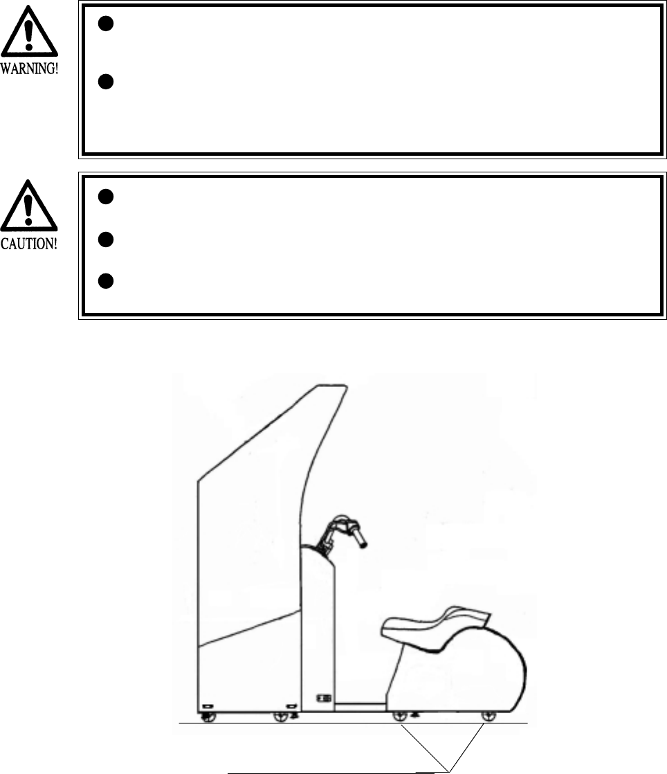
When moving the machine, be sure to unplug the power plug. Moving the
machine with the plug as is inserted can damage the power cord and cause fire
and electric shock hazards.
When moving the machine on the floor, retract the Adjusters and ensure that
Casters make contact with the floor. During transportation, pay careful
attention so that Casters do not tread power cords and earth wires. Damaging
the power cords can cause electric shock or short circuit.
6.
PRECAUTIONS TO BE HEEDED WHEN MOVING THE MACHINE
Have casters make contact with the floor.
When moving the product, do not push the Front Glass. The Glass part could
be damaged and glass fractions may cause injury.
When lifting the cabinet, be sure to hold the grip portions or bottom part.
Failure to observe this may damage parts and cause injury.
Do not push the Billboard. Failure to observe this may damage the installation
portions and cause unexpected accidents.
17
7. CONTENTS OF GAME
The following explanations apply to the case the product is functioning satisfactorily. Should
there be any moves different from the following contents, some sort of faults may have
occurred. Immediately look into the cause of the fault and eliminate the cause thereof to ensure
satisfactory operation.
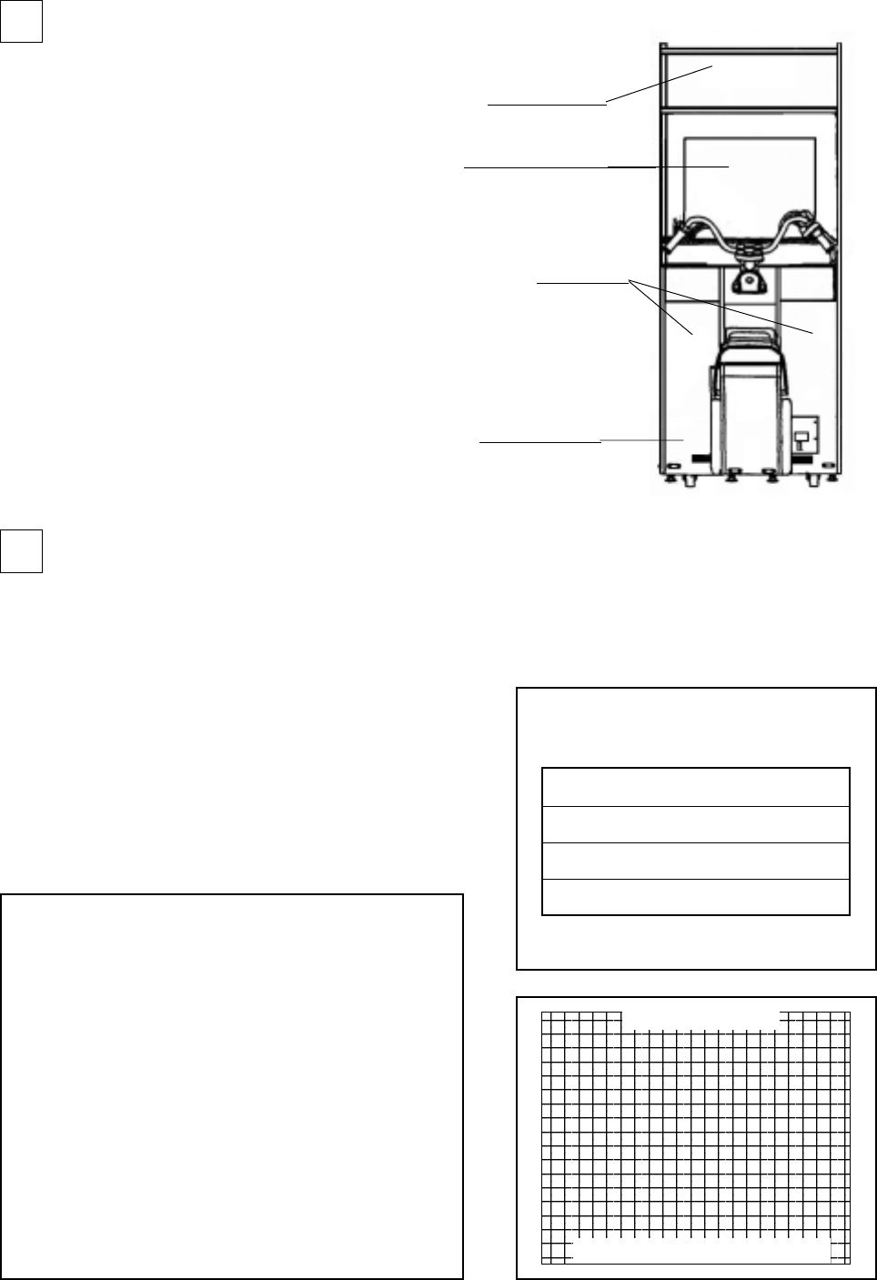
The 2 Fluorescent Lamps of the product are always lit when the product is energized. During
Advertise, the 2 Speakers and SUPERWOOFER output Advertise sounds, and Advertise images
are outputted on to the monitor. Note that setting to NO SOUND OUTPUT during Advertise is
possible (refer to the SERVICE MANUAL).
Accelerator Grip
FIG. 7 a
Fluorescent lamps is always on.
Emits sounds.
Image output on the monitor.
Rear Brake Pedal
Coin Inlet
Steering Wheel(Handlebar)
START button
Front Brake

18
•WILD RIDERS is a motorbike action game, where you play the ace rider of motorbike team
who should run away to the goal without being caught by the Police Inspector who is
chasing you.
•Throw coins for one play session into the slot. Then, press the START button to display the
Select Screen.
Select either character from the two riders (man and woman).
Selection of the character determines the motorbike type. Each motorbike has its specific
characteristics; the key to success in runaway is to take full advantage of its characteristics.
• By determining the character while stepping on the rear brake pedal, the instructions about
operating the handlebar will be skipped in the game session.
•Once the Select Screen closes, the Game Screen displays.
Once the game session starts, the Police Inspector (on a patrol car) begins to chase you. Run
away toward the goal according to the arrows being displayed along the road.
•The distance meter located at the top of the screen indicates the distance from the Police
Inspector. If it indicates 0, the game is over.
•You encounter several action points and should clear them by your motorbike action.
Two types of motorbike actions are available: Jump and Slide.
At a Jump point (orange), jump it by pulling off the handlebar. At a Slide point (green), push
the handlebar inward for sliding.
If you succeed in each of the actions, you can enlarge the spacing from the Police Inspector.
If you fail in it, this spacing reduces reversely.
•If you reach the goal without being caught by the Police Inspector, you get Game Clear and
see the Ending view.
•After the game ends, you can view the whole course map to examine to what point you have
been able to run away.
•If you acquire a high score at the end of the game, you may go to the Name Entry and be
able to enter the initials of your name and so on.
HOW TO PLAY
19
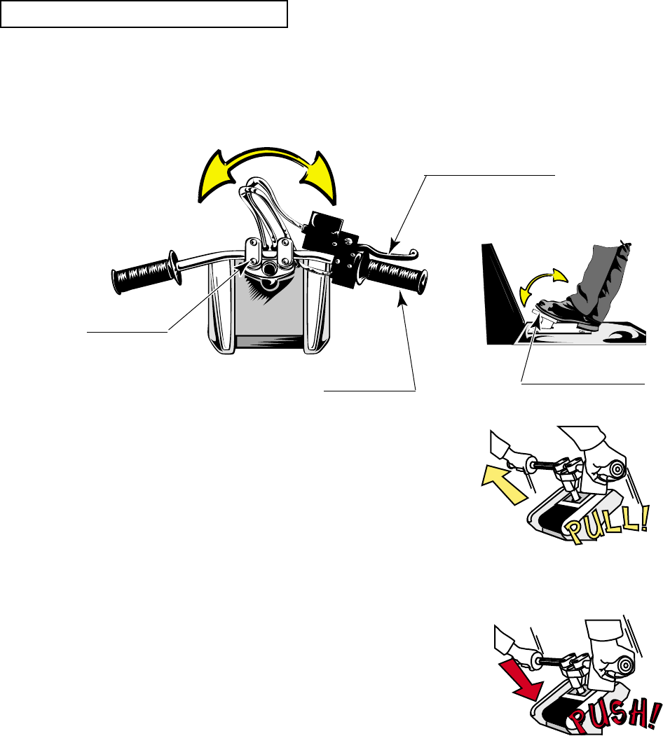
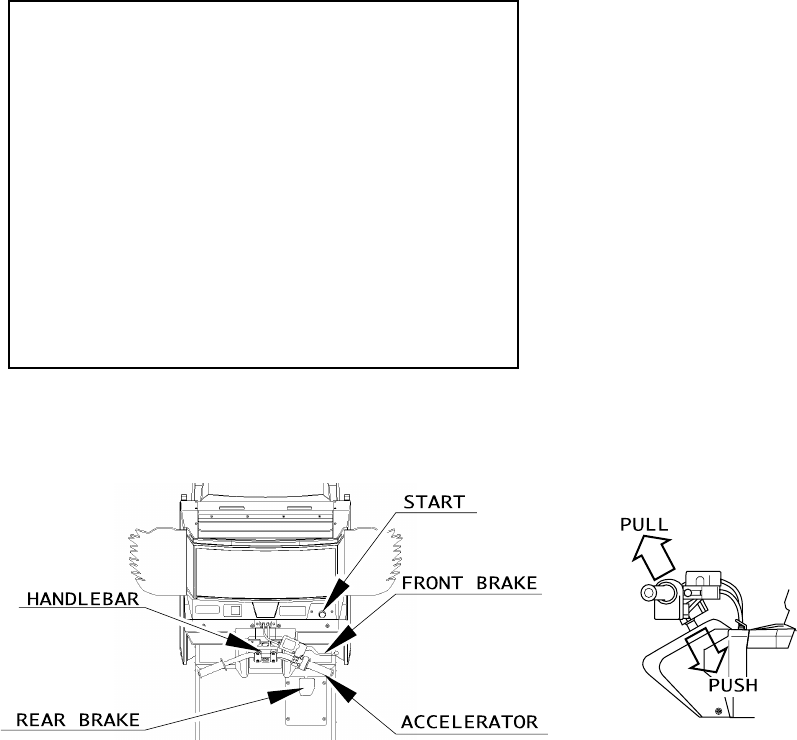
Basic operations include using the accelerator for accelerating the speed, using the brake for
reducing the speed, and using the handlebar for cornering to the left or right.
Nothing short of this game enables the following special operations:
"Pull off Handlebar": The motorbike is jumped by
pulling off the handlebar at a
Jump point, indicated by an
orange line. In addition, pulling
off the handlebar during usual
running allows you to enjoy a
wheelie of the motorbike.
"Push Handlebar": When you push the handlebar
at a Slide point, indicated by a
green line, the motorbike slides.
Pushing the handlebar during
usual running also slides the
motorbike.
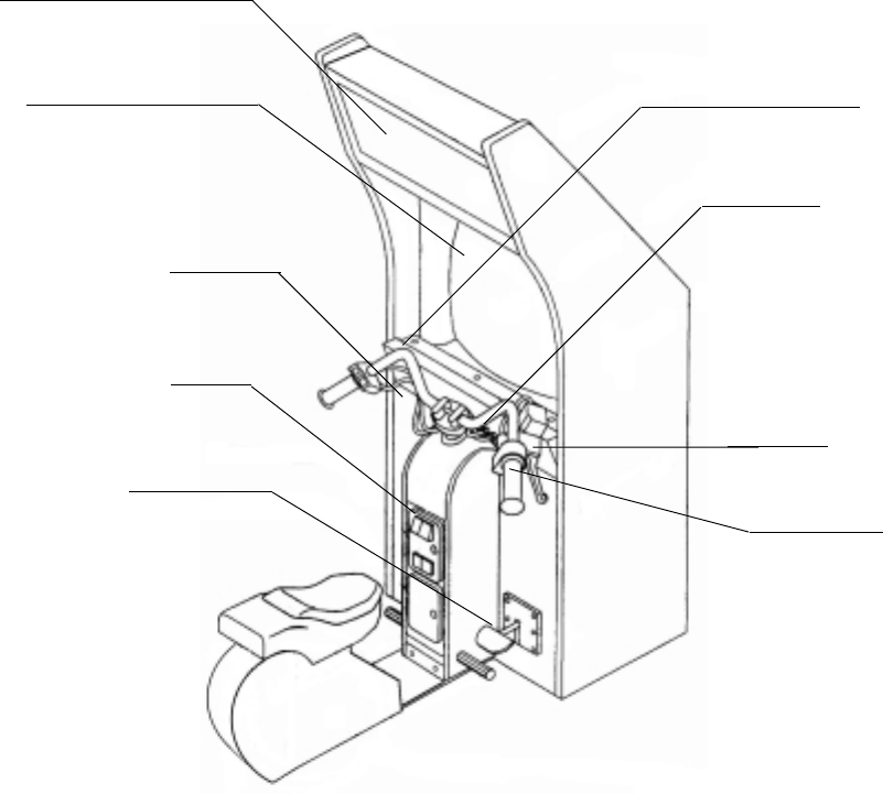
FRONT BRAKE LEVER
REAR BRAKE PEDAL
ACCELERATOR
HANDLE BAR
FIG. 7 b
INSTRUCTIONS ON OPERATIONS
20
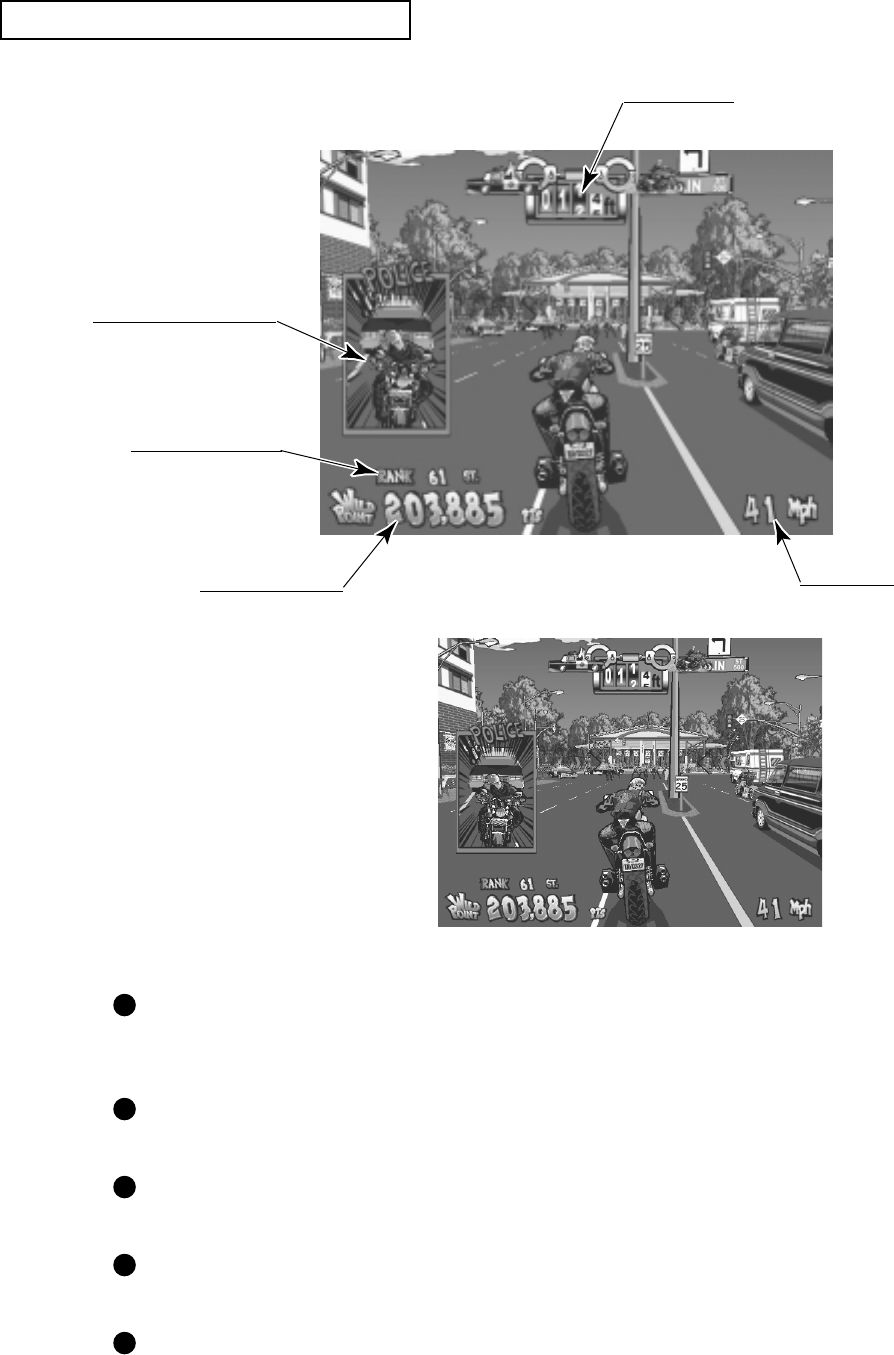
Distance Meter
Your current ranking
Speedometer
Score (Wild Points)
Police Inspector Window
FIG. 7 c
DESCRIPTION OF GAME SCREEN
Distance Meter: Indicates the distance from the Police Inspector. When it
indicates 0, the game is over. <In the US version, the value is
indicated in ft (feet).>
Ranking: Indicates your current ranking. As you get a higher score, your
ranking rises.
Speedometer: Indicates the speed of the motorbike. <In the US version, the
value is indicated in mph (miles per hour).>
Score (Wild Points): Each time you succeed a motorbike action or send a small
object (e.g., flowerpot) flying, this is counted as an score added.
Police Inspector Window: Displays when the distance from the Police Inspector reduces
within the predetermined value, in order to notify you that he is
just behind you.
FIG. 7 d US version screen

21
8. EXPLANATION OF TEST AND DATA DISPLAY
By operating the switch unit, periodically perform the tests and data check. When installing the
machine initially or collecting cash, or when the machine does not function correctly, perform
checking in accordance with the explanations given in this section.
The following shows tests and modes that should be utilized as applicable.
NAOMI 2 GAME BOARD is used for the product. The system of this game board allows
another game to be played by replacing the ROM Board Case mounted on the NAOMI 2 CASE.
As such, the Test Mode of this system consists of the System Test Mode for the system to
execute SELF-TEST, COIN ASSIGNMENTS, etc. used in common for the machines
employing the NAOMI 2 BOARD, and the Game Test Mode for the specific product to execute
Input/Output test for the operation equipment, difficulty setting, etc.
8-2E,8-2F,8-3D
8-3B
8-3C
8-2A, 8-2J
8-2A, 8-2J
8-2A, 8-2J
8-3D
8-3B
8-3C
8-3B
8-3E
9,10
8-2D
11
8-2A, 8-2J
8-2C
8-2G
8-3F
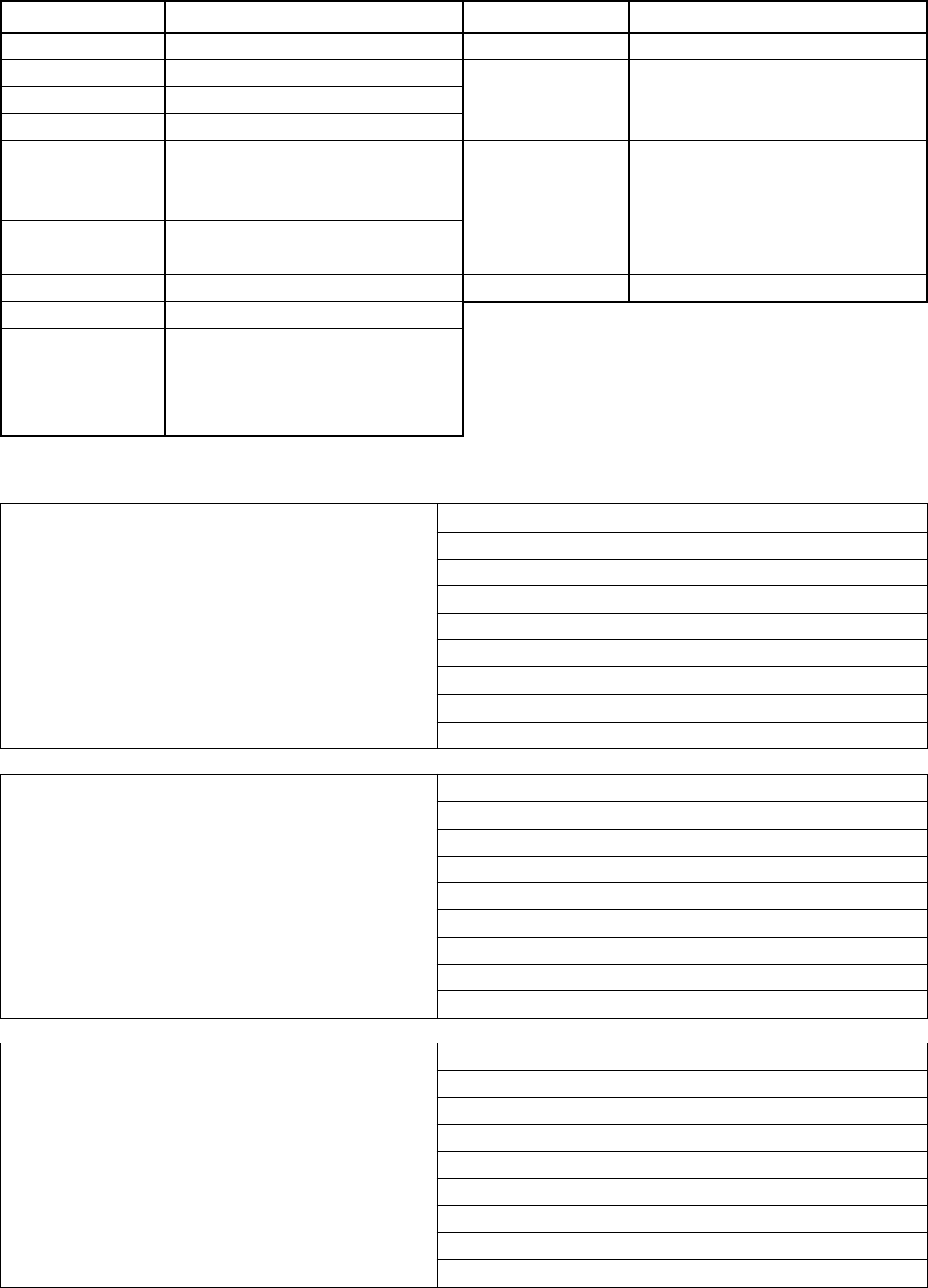
TABLE 8 EXPLANATION OF TEST MODE
ITEMS DESCRIPTION
INSTALLATION
OF MACHINE
MEMORY
PERIODIC
SERVICING
CONTROL
SYSTEM
MONITOR
IC BOARD
DATA CHECK
When the machine is installed, perform the following:
1. Check to ensure each is the standard setting at shipment.
2. Check each Input equipment in the INPUT TEST mode.
3. Check each Output equipment in the OUTPUT TEST mode.
4. Test on-IC-Board IC's in the SELF-TEST mode.
This test is automatically executed by selecting RAM TEST, or
ROM BOARD TEST in the Menu mode.
Periodically perform the following:
1. MEMORY TEST
2. Ascertain each setting.
3. To test each Input equipment in the INPUT TEST mode.
4. To test each Output equipment in the OUTPUT TEST mode.
1. To check each Input equipment in the INPUT TEST mode.
2. Adjust or replace each Input equipment.
3. If the problem still remains unsolved, check each equipment's
mechanism movements.
In the Monitor Adjustment mode, check to see if Monitor
(Projector) adjustments are appropriate.
1. MEMORY TEST
2. In the SOUND TEST mode, check the sound related ROMs.
Check such data as game play time and histogram to adjust the
difficulty level, etc.
REFERENCE
SECTIONS
22
8 - 1 SWITCH UNIT AND COIN METER
Adjust to the optimum sound volume by considering the environmental
requirements of the installation location.
If the COIN METER and the game board are electrically disconnected, game
play is not possible.
Never touch places other than those specified. Touching places not specified can
cause electric shock and short circuit hazards.
STOP
IMPORTANT
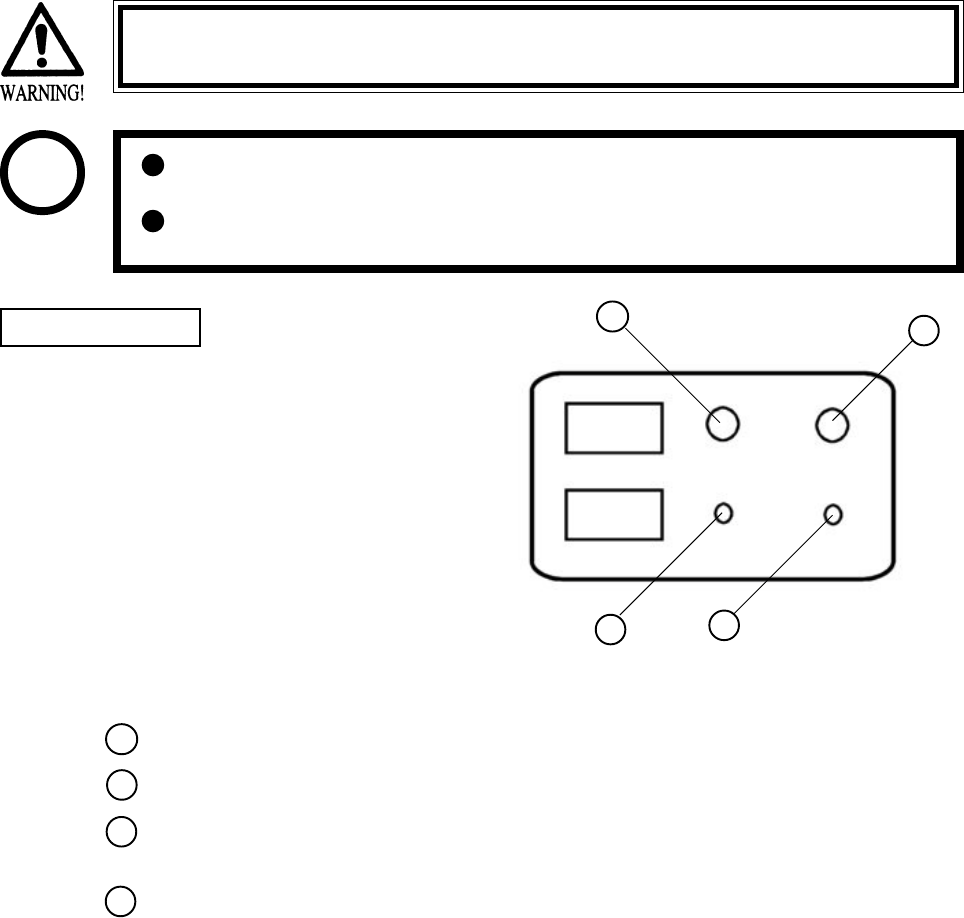
FIG. 8. 1 a SWITCH UNIT
Open the coin chute door, and the switch
unit shown will appear. The function of
each SW is as follows:
SWITCH UNIT
SPEAKER VOLUME: Sound volume can be adjusted for the 2 Speakers.
WOOFER VOLUME: Sound volume can be adjusted for the WOOFER.
TEST BUTTON: For the handling of the TEST BUTTON, refer to the
following pages.
SERVICE BUTTON: Gives credits without registering on the coin meter.
SPEAKER VOL
WOOFER VOL
TEST
SERVICE
1
2
3
4
12
34
23
8 - 2 SYSTEM TEST MODE
This test mode mainly allows the IC Board to be checked for accurate functioning, monitor
color to be adjusted as well as COIN ASSIGNMENTS and GAME ASSIGNMENTS to be
adjusted.
TEST ITEM SELECT
After turning power on, press the TEST button to have the following test item menu displayed.
Press the SERVICE button to move the arrow. Bring the arrow to the desired item and press the
TEST button.
Upon finishing the test, bring the arrow to EXIT and press the TEST button to return to the
Game mode.
The contents of setting changes in SYSTEM ASSIGNMENTS, COIN
ASSIGNMENTS, and GAME TEST MODE are stored when the test mode is
EXITed. If the power is turned off before EXITing, the contents of setting
changes are ineffective. Be very careful of this point.
STOP
IMPORTANT
SYSTEM MENU
RAM TEST
JVS TEST
SOUND TEST
C.R.T. TEST
SYSTEM ASSIGNMENTS
COIN ASSIGNMENTS
BOOKKEEPING
BACKUP DATA CLEAR
CLOCK SETTING
ROM BOARD TEST
GAME TEST MODE
[WILD RIDERS XXXXXXXXX]
-> EXIT
SELECT WITH SERVICE BUTTON
AND PRESS TEST BUTTON
1
2
3

24
A. RAM TEST
This allows for checking the functioning of the RAM on the NAOMI 2 Main BD.
"GOOD" is displayed for satisfactory RAMs, and "BAD" is indicated for irregular RAMs, if
any.
"TESTING NOW" shows up (flashing) on the screen during the test.
Returns to the menu screen when the TEST button is pressed after the test is over.
RAM TEST
TESTING NOW
IC29 GOOD
IC35 GOOD
IC09 GOOD IC10 GOOD
IC11 GOOD IC12 GOOD
IC16 GOOD IC18 GOOD
IC20 GOOD IC22 GOOD
IC17 GOOD IC19 GOOD
IC21 GOOD IC23 GOOD
IC106 GOOD IC107 GOOD
IC108 GOOD IC109 GOOD
IC111 GOOD IC113 GOOD
IC115 GOOD IC117 GOOD
IC112 GOOD IC114 GOOD
IC116 GOOD IC118 GOOD
PRESS TEST BUTTON TO EXIT
25
B. JVS TEST
In this test, Specifications of the I/O Board connected to NAOMI 2 can be checked, and INPUT
TEST can be performed. First, I/O Board Specifications are displayed.
Select with the SERVICE button and press the TEST button.
(A) INPUT TEST : Proceeds to the INPUT TEST of I/O BOARD being displayed.
(B) NEXT NODE : In the case where more than 2 I/O Boards are connected, proceeds to
the next I/O Board.
(C) EXIT : Returns to the menu mode.
INPUT TEST SCREEN
When INPUT is performed for the switches
of Control Panel, etc., the value changes to
1 from 0.
If the Coin SW is inputted, the count starts.
When the TEST MODE is finished, the
count is cleared and returned to[0000].
Analogue values are displayed between
0000 and FF00.
JVS TEST
INPUT TEST
NEXT NODE
-> EXIT
NODE 1/1
SWITCH
SYSTEM 00000000
PLAYER1 00000000
00000000
PLAYER2 00000000
00000000
COIN
0000 0000
ANALOG
0000 0000 0000 0000
0000 0000 0000 0000
SELECT WITH SERVICE BUTTON
AND
PRESS TEST BUTTON
JVS TEST
INPUT TEST (A)
NEXT NODE (B)
-> EXIT (C)
NODE 1/1
NAME SEGA ENTERPRISES,LTD.
I/O BD JVS
837-13551
Ver 1.00
CMD VER 1.1
JVS VER 2.0
COM VER 1.0
SWITCH 2PLAYER(S) 13BITS
COIN 2SLOT
ANALOG 8CH
ROTARY 0CH
KEYCODE 0
SCREEN X:0 Y:0 CH:0
CARD OSLOT
HOPPER OUT 0CH
DRIVER OUT 6SLOT
ANALOG OUT 0CH
CHARACTER CHARA:0 LINE:0
BACKUP 0
SELECT WITH SERVICE BUTTON
AND
PRESS TEST BUTTON
Name and version of I/O BOARD.
123
26
C. SOUND TEST
Sound Output test can be performed. Beep sounds can be emitted from each of left/right Speakers.
D. C.R.T. TEST
1) RGB COLOR ADJUSTMENT SCREEN
In this page, monitor color can be checked.
Each of red, green, and blue is the darkest at the
leftmost end, and becomes brighter towards the
right-hand end in 31 gradations. Monitor
brightness is satisfactory if the white color bar
is black at the left end and if it is white at the
right end.
Press the TEST button to proceed to the next
page.
2) MONITOR SIZE ADJUSTMENT SCREEN
In this page, monitor size can be checked.
C.R.T. TEST 1/2
1 32
RED
GREEN
BLUE
WHITE
PRESS TEST BUTTON TO CONTINUE
C.R.T. TEST 2/2
PRESS TEST BUTTON TO EXIT
Adjust so that the checkered patterns do not go
beyond the screen.
Press the TEST button to return to the menu
mode.
SOUND TEST
RIGHT SPEAKER OFF
LEFT SPEAKER OFF
-> EXIT
SELECT WITH SERVICE BUTTON
AND PRESS TEST BUTTON
Emitted from the right-hand side Speaker.
Emitted from the left-hand side Speaker.
Returns to the menu mode.
27
E. SYSTEM ASSIGNMENTS
The settings of cabinet and board can be changed. Game related assignments such as game
difficulty, etc. are performed in K. GAME TEST MODE.
Press the SERVICE button to move the arrow. Bring the arrow to the desired item.
Press the TEST button to change the setting.
Upon finishing the setting, move the arrow to EXIT and press the TEST button.
(A) CABINET TYPE (1PLAYER(S), 2PLAYER(S), 3PLAYER(S), 4PLAYER(S))
Sets the number of players between 1 and 4.
Fix setting to 1 PLAYER(S).
(B) ADVERTISE SOUND (ON, OFF)
Sets whether ADVERTISE sound is to be emitted or not.
(C) MONITOR TYPE (HORIZONTAL, VERTICAL)
Sets the on-screen display to the positional direction of monitor (HORIZONTAL/VERTICAL)
Fix setting to HORIZONTAL.
HORIZONTAL: Normal on-screen display
VERTICAL: On-screen display when the monitor is vertically positioned as against
normal HORIZONTAL position.
(D) SERVICE TYPE (COMMON, INDIVIDUAL)
Sets the functioning of when the SERVICE button is pressed, in case that several SERVICE
buttons exist.
Fix setting to COMMON.
COMMON: By pressing any SERVICE button, Service credit can be obtained for all
Players.
INDIVIDUAL: By pressing SERVICE button, Service credit can be obtained for the Player
corresponding to the SERVICE button pressed.
SYSTEM ASSIGNMENTS
CABINET TYPE 1PLAYER(S) (A)
ADVERTISE SOUND ON (B)
MONITOR TYPE HORIZONTAL (C)
SERVICE TYPE COMMON (D)
-> EXIT
SELECT WITH SERVICE BUTTON
AND
PRESS TEST BUTTON
1
2
3
28
F. COIN ASSIGNMENTS
In this mode, the setting of incremental credit increase as against coin insertion can be changed.
Press the SERVICE button to move the arrow. Bring the arrow to the desired item.
Press the TEST button to change the setting.
Upon finishing the setting, bring the arrow to EXIT and press the TEST button.
COIN ASSIGNMENTS
COIN CHUTE TYPE COMMON (A)
COIN/CREDIT SETTING #1 (B)
COIN CHUTE #1
1 COIN 1 CREDIT
COIN CHUTE #2
1 COIN 1 CREDIT
(C)
(G)
MANUAL SETTING
SEQUENCE SETTING
->EXIT
SELECT WITH SERVICE BUTTON
AND PRESS TEST BUTTON
COIN ASSIGNMENTS
COIN CHUTE TYPE INDIVIDUAL
COIN/CREDIT SETTING #1
COIN CHUTE #1
1 COIN 1 CREDIT
MANUAL SETTING
SEQUENCE SETTING
->EXIT
SELECT WITH SERVICE BUTTON
AND PRESS TEST BUTTON
Setting to COMMON Setting to INDIVIDUAL
(A) COIN CHUTE TYPE (COMMON, INDIVIDUAL)
Fix setting to COMMON.
COMMON
This setting is for the cabinet which has a coin chute(s) for common use by plural players. Up
to 2 Coin Chutes (#1 and #2) can be used and also, (B) COIN/CREDIT SETTING ratio can be
set separately for #1 and #2.
INDIVIDUAL
This setting is for the cabinet in which each player uses an independent coin chute. Coins
inserted by each player are handled as the player's credits. Depending on the CABINET TYPE
setting in the SYSTEM ASSIGNMENTS and the functioning of the connected I/O Board, the
number of Coin SW INPUT ports varies between 1 and 4. (B) COIN/CREDIT SETTING ratio
is common for eath Coin Chute.
(B) COIN/CREDIT SETTING ( # 1 ~ # 27)
Sets the credit increase increment per coin insertion. There are 27 settings from #1 to #27,
expressed in credit(s) as against coins inserted. #27 refers to FREE PLAY.
For details, refer to Table 1 (COMMON) and Table 2 (INDIVIDUAL).
1
2
3

29
(C) MANUAL SETTING
The Credit's incremental increase settings as against a coin insertion are shown in further details
than in (B) above (refer to Table 3). Also, note that when this MANUAL SETTING is
performed, (B) COIN CREDIT setting becomes ineffective.
MANUAL SETTING
COIN ASSIGNMENTS
MANUAL SETTING
COIN TO CREDIT 1 (D)
BONUS ADDER NO BONUS ADDER (E)
COIN CHUTE #1 MULTIPLIER
1 COIN COUNT AS 1 COIN
COIN 1 2 3 4 5 6 7 8 9
CREDIT 1 2 3 4 5 6 7 8 9
COIN CHUTE #2 MULTIPLIER
1 COIN COUNT AS 1 COIN
COIN 1 2 3 4 5 6 7 8 9
CREDIT 1 2 3 4 5 6 7 8 9
SEQUENCE SETTING (G)
->EXIT
SELECT WITH SERVICE BUTTON
AND PRESS TEST BUTTON
(D) COIN TO CREDIT
Determines COIN/CREDIT setting.
(E) BONUS ADDER
This sets how many coins should be inserted to obtain one SERVICE COIN.
(F) COIN CHUTE ( # 1 / # 2 ) MULTIPLIER
This sets how many tokens one coin represents.
Setting to COMMON Setting to INDIVIDUAL
COIN ASSIGNMENTS
MANUAL SETTING
COIN TO CREDIT 1
BONUS ADDER NO BONUS ADDER
COIN CHUTE MULTIPLIER
1 COIN COUNT AS 1 COIN
COIN 1 2 3 4 5 6 7 8 9
CREDIT 1 2 3 4 5 6 7 8 9
SEQUENCE SETTING
->EXIT
SELECT WITH SERVICE BUTTON
AND
PRESS TEST BUTTON

30
NAME OF SETTING COIN CHUTE 1 COIN CHUTE 2
SETTING #1 1 COIN 1 CREDIT 1 COIN 1 CREDIT
SETTING #2 1 COIN 2 CREDITS 1 COIN 1 CREDIT
SETTING #3 1 COIN 3 CREDITS 1 COIN 1 CREDIT
SETTING #4 1 COIN 4 CREDITS 1 COIN 1 CREDIT
SETTING #5 1 COIN 5 CREDITS 1 COIN 1 CREDIT
SETTING #6 1 COIN 2 CREDITS 1 COIN 2 CREDITS
SETTING #7 1 COIN 5 CREDITS 1 COIN 2 CREDITS
SETTING #8 1 COIN 3 CREDITS 1 COIN 3 CREDITS
SETTING #9 1 COIN 4 CREDITS 1 COIN 4 CREDITS
SETTING #10 1 COIN 5 CREDITS 1 COIN 5 CREDITS
SETTING #11 1 COIN 6 CREDITS 1 COIN 6 CREDITS
SETTING #12 2 COINS 1 CREDIT 2 COINS 1 CREDIT
SETTING #13 1 COIN 1 CREDIT 2 COINS 1 CREDIT
SETTING #14 1 COIN 2 CREDITS 2 COINS 1 CREDIT
SETTING #15 1 COIN 1 CREDIT 1 COIN 1 CREDIT
2 COINS 3 CREDITS 2 COINS 3 CREDITS
SETTING #16 1 COIN 3 CREDITS 1 COIN 1 CREDIT
2 COINS 3 CREDITS
SETTING #17 3 COINS 1 CREDIT 3 COINS 1 CREDIT
SETTING #18 4 COINS 1 CREDIT 4 COINS 1 CREDIT
SETTING #19 1 COIN 1 CREDIT 1 COIN 1 CREDIT
2 COINS 2 CREDITS 2 COINS 2 CREDITS
3 COINS 3 CREDITS 3 COINS 3 CREDITS
4 COINS 5 CREDITS 4 COINS 5 CREDITS
SETTING #20 1 COIN 5 CREDITS 1 COIN 1 CREDIT
2 COINS 2 CREDITS
3 COINS 3 CREDITS
4 COINS 5 CREDITS
SETTING #21 5 COINS 1 CREDIT 5 COINS 1 CREDIT
SETTING #22 1 COIN 2 CREDITS 3 COINS 1 CREDIT
5 COINS 2 CREDITS
SETTING #23 2 COINS 1 CREDIT 2 COINS 1 CREDIT
4 COINS 2 CREDITS 4 COINS 2 CREDITS
5 COINS 3 CREDITS 5 COINS 3 CREDITS
SETTING #24 1 COIN 3 CREDITS 2 COINS 1 CREDIT
4 COINS 2 CREDITS
5 COINS 3 CREDITS
SETTING #25 1 COIN 1 CREDIT 1 COIN 1 CREDIT
2 COINS 2 CREDITS 2 COINS 2 CREDITS
3 COINS 3 CREDITS 3 COINS 3 CREDITS
4 COINS 4 CREDITS 4 COINS 4 CREDITS
5 COINS 6 CREDITS 5 COINS 6 CREDITS
SETTING #26 1 COIN 6 CREDITS 1 COIN 1 CREDIT
2 COINS 2 CREDITS
3 COINS 3 CREDITS
4 COINS 4 CREDITS
5 COINS 6 CREDITS
SETTING #27 FREE PLAY FREE PLAY
Table 1: COIN/CREDIT SETTING (COIN CHUTE COMMON TYPE)
31
NAME OF SETTING
EACH SEAT'S COIN CHUTE
SETTING #1 1 COIN 1 CREDIT
SETTING #2 1 COIN 2 CREDITS
SETTING #3 1 COIN 3 CREDITS
SETTING #4 1 COIN 4 CREDITS
SETTING #5 1 COIN 5 CREDITS
SETTING #11 1 COIN 6 CREDITS
SETTING #12 2 COINS 1 CREDIT
SETTING #15 1 COIN 1 CREDIT
2 COINS 3 CREDITS
SETTING #17 3 COINS 1 CREDIT
SETTING #18 4 COINS 1 CREDIT
SETTING #19 1 COIN 1 CREDIT
2 COINS 2 CREDITS
3 COINS 3 CREDITS
4 COINS 5 CREDITS
NAME OF SETTING
EACH SEAT'S COIN CHUTE
SETTING #21 5 COINS 1 CREDIT
SETTING #23 2 COINS 1 CREDIT
4 COINS 2 CREDITS
5 COINS 3 CREDITS
SETTING #25 1 COIN 1 CREDIT
2 COINS 2 CREDITS
3 COINS 3 CREDITS
4 COINS 4 CREDITS
5 COINS 6 CREDITS
SETTING #27 FREE PLAY
Table 2: COIN/CREDIT SETTING (COIN CHUTE INDIVIDUAL TYPE)
Table 3: MANUAL SETTING
COIN TO CREDIT 1 COIN 1 CREDIT
2 COINS 1 CREDIT
3 COINS 1 CREDIT
4 COINS 1 CREDIT
5 COINS 1 CREDIT
6 COINS 1 CREDIT
7 COINS 1 CREDIT
8 COINS 1 CREDIT
9 COINS 1 CREDIT
BONUS ADDER NO BONUS ADDER
2 COINS GIVE 1 EXTRA COIN
3 COINS GIVE 1 EXTRA COIN
4 COINS GIVE 1 EXTRA COIN
5 COINS GIVE 1 EXTRA COIN
6 COINS GIVE 1 EXTRA COIN
7 COINS GIVE 1 EXTRA COIN
8 COINS GIVE 1 EXTRA COIN
9 COINS GIVE 1 EXTRA COIN
COIN CHUTE (# 1 / # 2) 1 COIN COUNTS AS 1 COIN
MULTIPLIER 1 COIN COUNTS AS 2 COINS
1 COIN COUNTS AS 3 COINS
1 COIN COUNTS AS 4 COINS
1 COIN COUNTS AS 5 COINS
1 COIN COUNTS AS 6 COINS
1 COIN COUNTS AS 7 COINS
1 COIN COUNTS AS 8 COINS
1 COIN COUNTS AS 9 COINS

32
(G) SEQUENCE SETTING
Number of credits required for starting game, etc. can be set.
Function varies depending on the specific games. To find out what kind of functions are
allotted to each sequence, or what is the initial value for each sequence, refer to the Instruction
Manual of the game connected. Each sequence can be set between 1 ~ 5 credit(s).
In cases of video games such as WILD RIDERS. :
SEQUENCE 1 : Number of credits required for game start (initial value=1)
SEQUENCE 2 ~ 8 : NOT USED.
COIN ASSIGNMENTS
SEQUENCE SETTING
SEQUENCE 1 1 CREDIT(S)
SEQUENCE 2 1 CREDIT(S)
SEQUENCE 3 1 CREDIT(S)
SEQUENCE 4 1 CREDIT(S)
SEQUENCE 5 1 CREDIT(S)
SEQUENCE 6 1 CREDIT(S)
SEQUENCE 7 1 CREDIT(S)
SEQUENCE 8 1 CREDIT(S)
-> EXIT
[WILD RIDERS XXXXXXXXXX]
DESCRIPTION OF SEQUENCE
1 CREDIT TO START
2 NO USE
3 NO USE
4 NO USE
5 NO USE
6 NO USE
7 NO USE
8 NO USE
SELECT WITH SERVICE BUTTON
AND
PRESS TEST BUTTON

33
G. BOOKKEEPING
• BOOKKEEPING 1/2
This allows such data as operating time/No. of coins inserted/ No. of credits to be checked.
Press the TEST button to proceed to BOOKKEEPING 2/2.
• BOOKKEEPING 2/2
Each sequence displays the frequency of functioning.
In cases of video games such as WILD RIDERS. :
P1 SEQ 1 : Play frequency of Player 1
P1 SEQ 2 ~ 8 : NOT USED.
BOOKKEEPING 1/2
TOTAL TIME
0D 00H 00M 00S
CREDIT 0
COIN 1 0
COIN 2 0
COIN 3 0
COIN 4 0
TOTAL COIN 0
COIN CREDIT 0
SERVICE CREDIT 0
TOTAL CREDIT 0
PRESS TEST BUTTON TO CONTINUE
BOOKKEEPING 2/2
P1 SEQ 1 0
P1 SEQ 2 0
P1 SEQ 3 0
P1 SEQ 4 0
P1 SEQ 5 0
P1 SEQ 6 0
P1 SEQ 7 0
P1 SEQ 8 0
PRESS TEST BUTTON TO EXIT

34
H. BACKUP DATA CLEAR
Clears the contents of BOOKKEEPING.
BACKUP DATA CLEAR
YES(CLEAR)
-> NO(CANCEL)
SELECT WITH SERVICE BUTTON
AND PRESS TEST BUTTON
When clearing, bring the arrow to YES by using the SERVICE button and press the TEST
button. Bring the arrow to NO and press the TEST button to have the menu mode return
without clearing the data. COMPLETED is displayed when clearing is completed. Press the
TEST button to return to the menu mode.
I. CLOCK SETTING
Set YEAR, MONTH, DAY, HOUR, and MINUTE for NAOMI 2 Main BD.
Select the desired item with the SERVICE button and press the TEST button to increase
the value. Upon finishing the SETTING, bring the arrow to EXIT and press the TEST
button to return to the menu mode.
CLOCK SETTING
1998 12/02 14:30 33 WED
YEAR
MONTH
DAY
HOUR
MINUTE
-> EXIT
SELECT WITH SERVICE BUTTON
AND PRESS TEST BUTTON

35
J. ROM BOARD TEST
In this test, on-ROM-BD ROM check is executed.
If GOOD is displayed below RESULT, it is satisfactory.
BYTE and WORD refers to the check sum of each unit.
K. GAME TEST MODE
Enters the TEST mode of the game connected. The TEST mode includes INPUT test, GAME
ASSIGNMENTS such as game difficulty and others, BOOKKEEPING, etc. Depending on
specific games, necessary items are added and unnecessary items removed. As such, the
contents thereof may be changed.
Program ROMs (IC22) do not display GOOD or BAD.
Press the TEST button to return to the menu mode.
GAME ROM TEST
[WILD RIDERS
XXXXXXX
]
NO. TYPE RESULT BYTE WORD
IC22 16M ---- 0123 4567
IC1 64M GOOD 0123 4567
IC2 64M GOOD 0123 4567
IC3 64M GOOD 0123 4567
IC4 64M GOOD 0123 4567
IC5 64M GOOD 0123 4567
IC6 64M GOOD 0123 4567
IC7 64M GOOD 0123 4567
IC8 64M GOOD 0123 4567
IC9 64M GOOD 0123 4567
IC10 64M GOOD 0123 4567
:
IC20 64M GOOD 0123 4567
PRESS TEST BUTTON TO EXIT

36
FIG. 8. 3 a MENU MODE
• Press the TEST button to display the SYSTEM TEST MODE MENU.
• By pressing the SERVICE button, move the arrow (->) to select the GAME TEST MODE.
• Press the TEST button to enter GAME TEST MODE. The screen displays the GAME TEST
MODE MENU.
• By pressing the SERVICE button, move the arrow (->) to select the desired item . Press the
TEST button to execute the selected item.
• Select EXIT and press the TEST button to exit from the GAME TEST MODE and return to
the SYSTEM TEST MODE MENU. Further, select EXIT and press the TEST button to
finish SYSTEM TEST MODE and return to the normal mode.
8 - 3 GAME TEST MODE
A. MENU MODE
SYSTEM TEST MODE MENU GAME TEST MODE MENU
SYSTEM MENU
RAM TEST
JVS TEST
SOUND TEST
C.R.T. TEST
SYSTEM ASSIGNMENTS
COIN ASSIGNMENTS
BOOKKEEPING
BACKUP DATA CLEAR
CLOCK SETTING
ROM BOARD TEST
-> GAME TEST MODE
[WILD RIDERS XXXXXXX]
EXIT
SELECT WITH SERVICE BUTTON
AND PRESS TEST BUTTON
GAME TEST MENU
INPUT TEST
OUTPUT TEST
GAME ASSIGNMENTS
VOLUME ADJUSTMENTS
BOOKKEEPING
BAUKUP DATA CLEAR
->EXIT
SELECT WITH SERVICE BUTTON
AND PRESS TEST BUTTON
37
B. INPUT TEST
Selecting INPUT TEST displays the following and allows the status of each switch to be
checked and the Volume value of each operative unit to be observed. In this mode, periodically
check the status of each switch and Volume.
FIG. 8. 3 ba INPUT TEST
INPUT TEST
HANDLEBAR 80
ACCELERATOR 00
FRONT BRAKE 00
REAR BRAKE 00
PUSH OFF
PULL OFF
START OFF
SERVICE OFF
TEST OFF
PRESS TEST AND SERVICE BUTTON TO EXIT
FIG. 8. 3 bb FIG. 8. 3 bc
• Press each switch. If the indicator to the right of the switch (currently Off) turns On, the
switch and its wiring are normal.
• While operating the handlebar and pedal, check the variation in indication of the volume
control value (HANDLEBAR, ACCELERATOR, FRONT BRAKE, REAR BRAKE). If the
normal variation does not result that follows the operations, see Sections 9 and 10.
• Pressing the TEST and SERVICE buttons together returns you to the Menu Screen.

38
C. OUTPUT TEST
Selecting OUTPUT TEST displays the following on the monitor and allows the status of
Lamp to be checked. In this mode, periodically check the lamp status.
Bring the arrow (->) to "START LAMP" and press the TEST button to alternate the right-
hand ON and OFF display of START LAMP.
Check to ensure that the lamp lights up when ON is displayed and goes off when OFF is
displayed. Bring the arrow (->) to "EXIT" and press the TEST button to return to the Test
Menu.
FIG. 8. 3 c OUTPUT TEST
OUTPUT TEST
START BUTTON LAMP OFF
->EXIT
SELECT WITH SERVICE BUTTON
AND PRESS TEST BUTTON

39
D. GAME ASSIGNMENTS
When GAME ASSIGNMENTS are selected, the following appears on the monitor and Game
Difficulty, etc. can be set. The setting change is not renewed until the TEST mode is exited.
After setting change, be sure to exit from the TEST mode.
FIG. 8. 3 d GAME ASSIGNMENTS
• Move the arrow with the SERVICE button to choose the setting change item.
Press the TEST button to change the difficulty.
• Bring the arrow to EXIT and press the TEST button to return to the menu mode.
GAME ASSIGNMENTS
DIFFICULTY NORMAL
ADVERTISE SOUND VOLUME 7
->EXIT
SELECT WITH SERVICE BUTTON
AND PRESS TEST BUTTON
DIFFICULTY : Setting the difficulty of the game
You can select one of 5 levels of "VERY EASY," "EASY,"
"NORMAL," "HARD," and "VERY HARD."
ADVERTISE SOUND VOLUME : For the advertisement sound volume, you can select one of 8
levels of "0" to "8".
The larger the value, the larger the sound volume ("0" is the
minimum).

40
E. VOLUME ADJUSTMENTS
If you select "VOLUME ADJUSTMENTS," the monitor screen lists the information below,
which lets you set the volume controls of each operations unit.
If the operability is poor or you have adjusted or replaced one or more volume controls, use this
mode to set them.
At this time, you must set the following four types of volume controls: HANDLEBAR,
ACCELERATOR, FRONT BRAKE, and REAR BRAKE.
The MAX. value, MIN. value for each and the HANDLEBAR's NEUTRAL value are to be set
as applicable.
FIG. 8. 3 e VOLUME ASSIGNMENTS
VOLUME ADJUSTMENTS
MIN MAX NEUTRAL
HANDLEBAR [ 00H ] [ FFH ] [ 80H ]
( 00H ) ( FFH ) ( 80H )
ACCELERATOR [ 00H ] [ FFH ] [ 00H ]
( 00H ) ( FFH )
FRONT BRAKE [ 00H ] [ FFH ] [ 00H ]
( 00H ) ( FFH )
REAR BRAKE [ 00H ] [ FFH ] [ 00H ]
( 00H ) ( FFH )
EXIT WITH SAVE
->EXIT WITHOUT SAVE
SELECT WITH SERVICE BUTTON
AND PRESS TEST BUTTON
Move the handlebar, the accelerator, and the front and rear brake pedals fully in the movable
range to set the proper volume control values.
Any value in brackets [ ] is the initial, or unadjusted value; any value in parentheses ( ) is the
currently backed up one.

41
HANDLEBAR : Fully move the handlebar to the clockwise or counterclockwise end.
Then, return it to the middle to place it in the state where no force is
applied to it.
ACCELERATOR : Fully turn the accelerator grip. Then, release it to return it to the state
where no force is applied to it.
FRONT BRAKE : Fully grasp the front brake lever. Then, release it to return it to the
state where no force is applied to it.
REAR BRAKE : Fully step on the rear brake pedal. Then, release it to return it to the
state where no force is applied to it.
The settings you have made are not updated until "EXIT WITH SAVE" is completed. To update
them, be sure to perform "EXIT WITH SAVE."
If you select "EXIT WITHOUT SAVE" before pressing the Test button, the system returns you
to the Menu Screen without updating the settings.
The range of appropriate volume levels are shown below. If a value outside the range is
indicated, the volume may get damaged, in which case the volume gear should be disengaged
once, and the angle of engagement should be modified (see Sections 10 and 11).
• HANDLEBAR 26H ~ 4AH 80H +/ - 5 C5H ~ EBH
Turn handlebar to the left Initial state Turn handlebar to the right
• ACCELERATOR 10H ~ 30H D0H ~ F0H
When your hand is removed from the grip Turn the grip all the way
• FRONT BRAKE 20H ~ 30H 9EH ~ ADH
When your hand is removed from the lever Pull the lever all the way
• REAR BRAKE 2DH ~ 33H B0H ~ BFH
When your foot is removed from the pedal Step on the pedal all the way
APPROPRIATE VOLUME LEVELS

42
F. BOOKKEEPING
If you select BOOKKEEPING, data about the current operation will be listed on two screens.
When you press the TEST button, you go to the next screen. When you press it while the second
screen remains in display, you return to the Menu Screen.
The first screen (1 of 2) lists data related to the progress of the play.
NUMBER OF GAMES : Total number of sessions played.
PLAY TIME : Time taken for the game.
FIG. 8. 3 f a BOOKKEEPING (1/2)
The second screen (2 of 2)
lists the number of sessions
played that corresponds to
each PLAY TIME. It
provides a guide for setting
up the difficulty and so on.
FIG. 8. 3 f b BOOKKEEPING (2/2)
BOOKKEEPING PAGE 1/2
NUMBER OF GAMES 0
PLAY TIME 0D 0H 0M 0S
AVERAGE PLAY TIME 0M 0S
LONGEST PLAY TIME 0M 0S
SHORTEST PLAY TIME 0M 0S
PRESS TEST BUTTON TO CONTINUE
BOOKKEEPING PAGE 2/2
TIME HISTOGRAM
0M 00S ~ 0M 29S 0
0M 30S ~ 0M 59S 0
1M 00S ~ 1M 29S 0
1M 30S ~ 1M 59S 0
2M 00S ~ 2M 29S 0
2M 30S ~ 2M 39S 0
3M 00S ~ 3M 29S 0
3M 30S ~ 3M 59S 0
4M 00S ~ 4M 29S 0
4M 30S ~ 4M 59S 0
5M 00S ~ 5M 29S 0
5M 30S ~ 5M 59S 0
6M 00S ~ 6M 29S 0
6M 30S ~ 6M 59S 0
7M 00S ~ 7M 29S 0
7M 30S ~ 7M 59S 0
8M 00S ~ 8M 29S 0
8M 30S ~ 8M 59S 0
9M 00S ~ 9M 29S 0
9M 30S ~ 9M 59S 0
OVER 10M 00S 0
PRESS TEST BUTTON TO EXIT

43
G. BACKUP DATA CLEAR
This allows the contents of BOOKKEEPING and the Ranking data to be cleared. Despite the
"clear" execution, the settings of GAME ASSIGNMENTS do not change. The contents of
BOOKKEEPING in the SYSTEM TEST mode are not cleared either.
When clearing, use the SERVICE button to bring the arrow (->) to "YES (CLEAR)" and press
the TEST button. When the data has been cleared, "COMPLETED" will be displayed. Press
the TEST button to return to the Menu mode. Bring the arrow to "NO (CANCEL)" and press
the TEST button to return to the Menu mode.
FIG. 8. 3 g BACKUP DATA CLEAR
BACKUP DATA CLEAR
YES(CLEAR)
->NO (CANCEL)
SELECT WITH SERVICE BUTTON
AND PRESS TEST BUTTON
44
9. CONTROL PANEL (HANDLE MECHA)
When closing the Control Panel, be very careful so as not to have hand and
fingers pinched in.
Be careful when handling the plastic made parts. Failure to observe this may
cause injury due to damage or fragments resulting from damage.
Before starting to work, ensure that the Power SW is OFF. Failure to observe
this can cause electric shock or short circuit.
Use care so as not to damage wirings. Damaged wiring can cause electric
shock or short circuit.
Do not touch undesignated places. Touching places not designated can cause
electric shock or short circuit.
This work should be performed by the Location's Maintenance Man or
Serviceman. Performing work by non-technical personnel can cause electric
shock hazard.
For the handlebar volume control, use the volume control with Part Number 220-
5373. For the front brake or accelerator volume control, use the volume control
with Part Number 220-5484. Do not confuse them.
STOP
IMPORTANT
The control panel of this product contains volume controls that are used to detect operations of
the handlebar, accelerator, and front brake.
Verify operations of the input devices at least once a month. If a failure is found, immediately
take proper action.
This document describes how to adjust and replace the volume controls.
The mechanisms of each input device is required to be greased every 3 months.
45
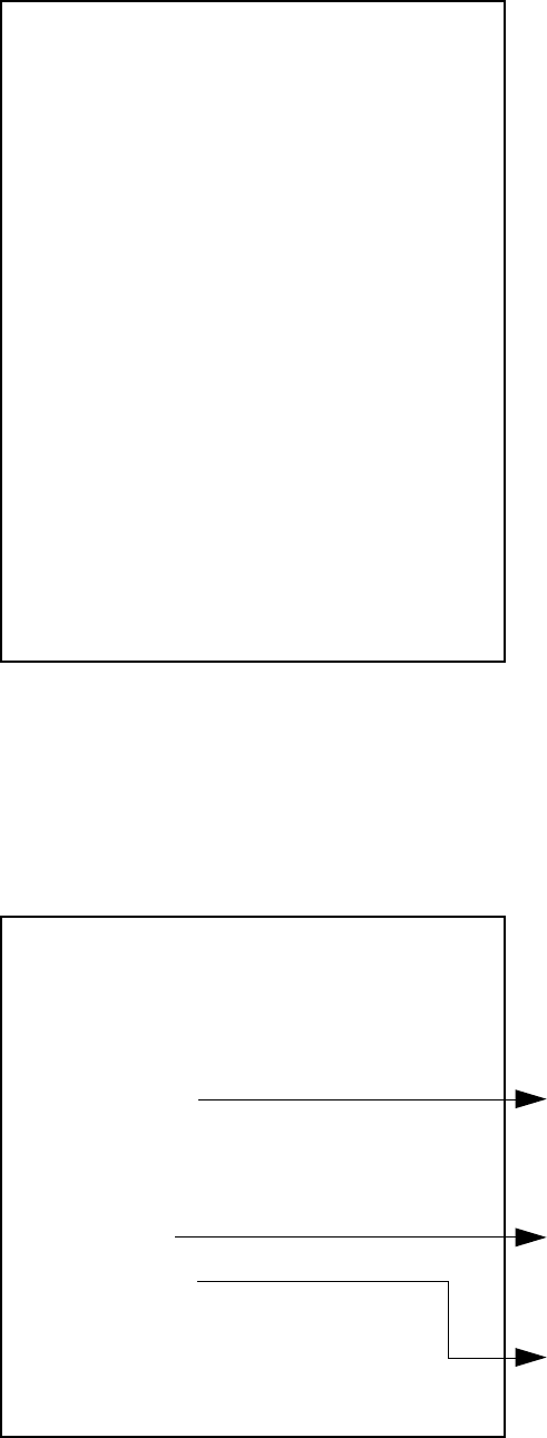
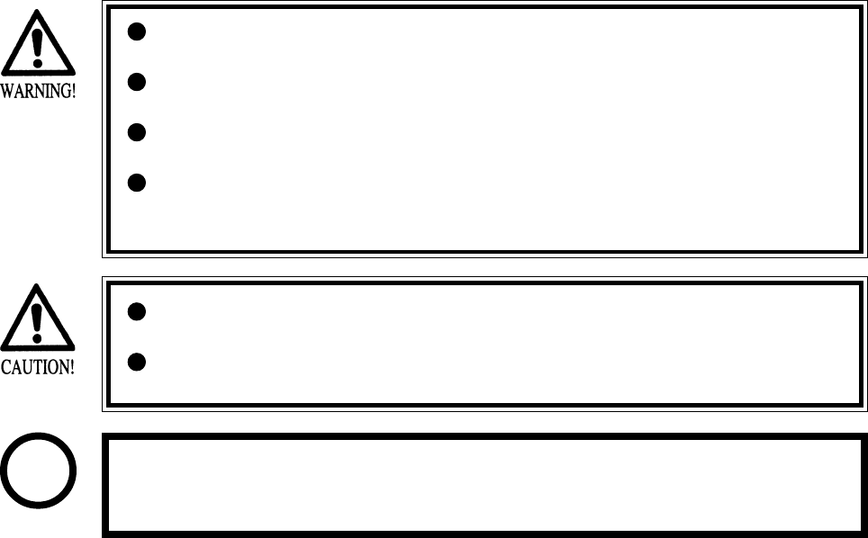
9 - 1 ADJUSTING / REPLACING THE HANDLEBAR VOLUME
The following procedure requires a wrench for tamperproof screw (for M4, accessories),
Phillips screwdriver (for M4), and the master key.
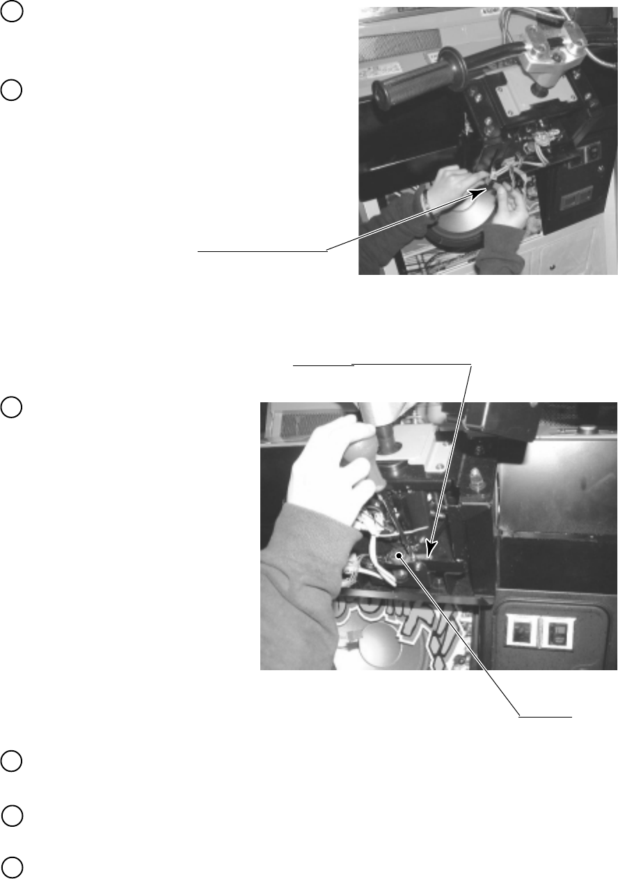
Remove the 4 tamperproof screws that
secure the Front lid to the base of the
handlebar. Remove the single tmaperlproof
bolt connecting the handlebar assembly to
the shaft. Then remove the handlebar
assembly momentarily.
Remove the Front Lid.
PHOTO 9. 1 a
ADJUSTlNG THE VOLUME
TAMPERPROOF SCREW (2)
TAMPERPROOF SCREW (2)
1
2
46
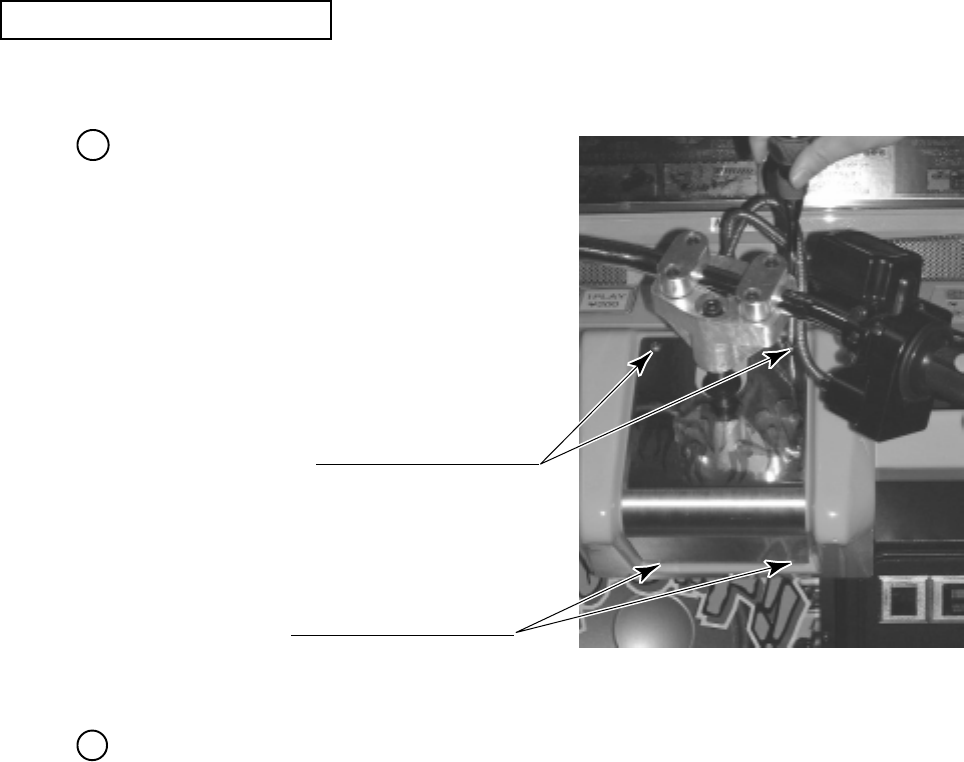
Loosen the 2 screws securing the VR
Bracket, and then this bracket can be moved
(PHOTO 10.1c).
PHOTO 9. 1 c
SCREW (2)
M4 X 12, w/flat & spring washers
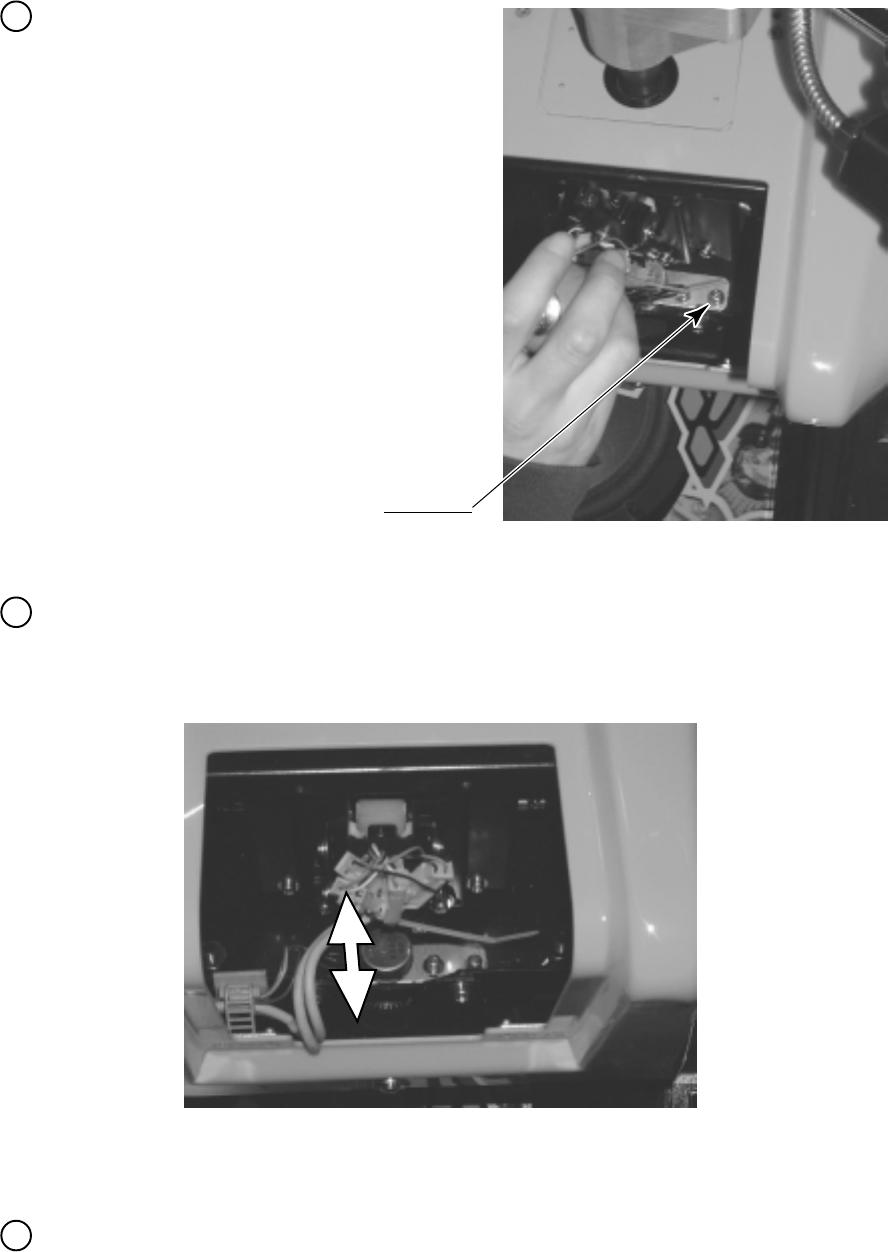
Move the VR Bracket back and forth to adjust the mesh of the gear.
Moving the VR Bracket toward you disengages the mesh of the gear. By turning the volume
control gear manually, vary the angle of the mesh (PHOTO 9.1d).
In the Test mode, check that the handlebar control volume varies properly.
PHOTO 9. 1 d
3
4
5
47
Before any action is taken, turn off the main
switch on the AC Unit in the back of the
game.
Remove the gear from the volume control. Remove the VR bracket. Cut the wire used for
soldering. Then replace the volume control.
Check that, when you fully turn the handlebar clockwise or counterclockwise, check that the
swing does not attempt to go outside the range of revolution of the volume control spindle.
Turn on the power. In the test mode, set the volume control value (see Section 8-3).
Disconnect the connector.
PHOTO 9. 1 g
SCREW (2)
M4 X 12, w/flat & spring washers
PHOTO 9. 1 h
Remove the 2 screws securing
the VR bracket. Then, remove
the volume control together
with the bracket
(PHOTO 10.1h).
VOLUME
220-5373
4
5
6
By reaching up through the coin door, untie
the cord clamp securing the wire of the
handlebar volume control, and pull off the
connector (PHOTO 10.1g).
1
2
3
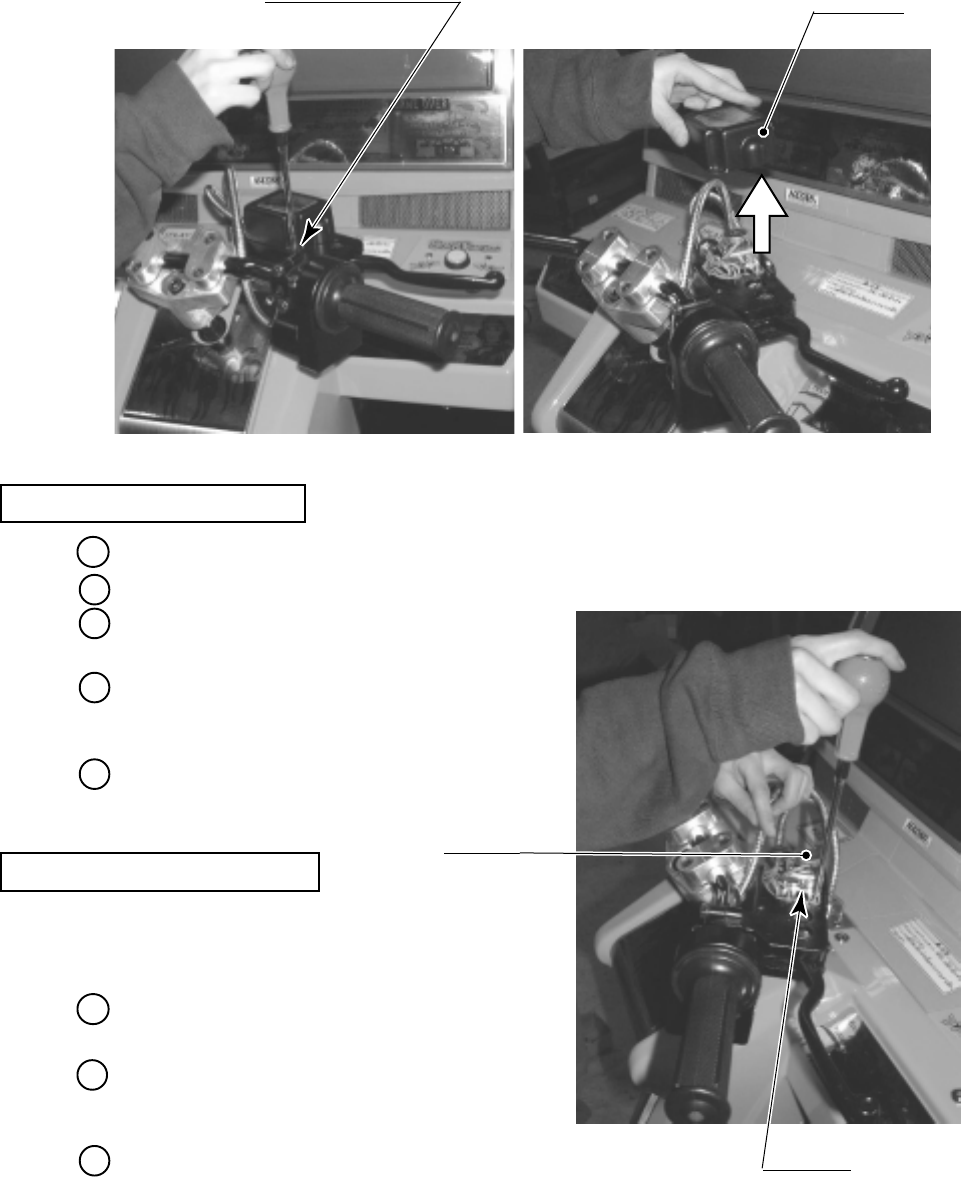
48
9 - 2 ADJUSTING / REPLACING THE FRONT BRAKE VOLUME
In the test mode, if the Front Brake Volume's value movements are irregular, adjust or replace
the Volume by using the following procedure.
This procedure requires a Phillips screwdriver (for M4), a hexagonal wrench with an opposite-
side distance of 1.5 mm, nippers, the master key, a solder iron, and solder.
Take out the 4 screws and remove the VR Cover.
The Front Brake Volume is inside the VR Cover.
Replace the Volume if it is malfunctioning.
Install the Volume in the manner so that 25H +/
- 5 is indicated when force is not exerted.
Remove the 2 screws which secure the VR
Bracket.
Remove the Volume Gear from the Volume
Shaft and remove the Volume from the VR
Bracket to replace the Volume.
After the replacement, be sure to perform the
Volume setting in the test mode.
Loosen the 2 screws which secure the VR Bracket to move the VR Bracket.
Move the VR Bracket to disengage gear mesh.
VOLUME REPLACEMENT
VOLUME ADJUSTMENT
TRUSS SCREW (4),black
M4 X 8 VR COVER
PHOTO 9. 2 a
VOLUME
220-5484
By adjusting gear mesh, fasten the 2 screws
which secure the VR Bracket.
Move the Brake Lever fully to the movable
range and check if the Volume Shaft's
revolvable range is exceeded.
After the adjustment, be sure to perform the
Volume setting in the test mode.
SCREW (2)
M4 X 8, w/flat & spring washers
PHOTO 9. 2 b
1
2
3
4
5
1
2
3
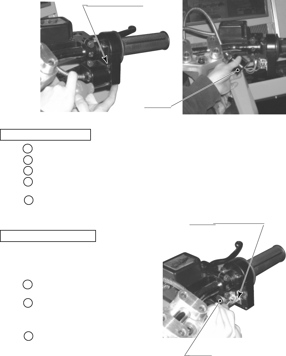
49
9 - 3 ADJUSTING / REPLACING THE ACCELERATOR VOLUME
In the test mode, if the Accelerator Volume's value movements are irregular, adjust or replace
the Volume by using the following procedure.
This procedure requires a short Phillips screwdriver(for M4), a hexagonal wrench with an
opposite-side distance of 1.5 mm, nippers, the master key, a solder iron, and solder.
Remove the 4 screws, and the VR Cover. The Accelerator Volume appears inside the Cover.
Replace the Volume if it is
malfunctioning. Install the Volume in
the manner so that 20H +/ - 5 is indicated
when force is not exerted.
Remove the screw which secures the VR
Bracket.
Remove the Volume Gear from the
Volume Shaft and remove the Volume
from the VR Bracket to replace the
Volume.
After the replacement, be sure to perform
the Volume setting in the test mode.
Loosen the screw which secures the VR Bracket to move the VR Bracket.
Move the VR Bracket to disengage gear mesh.
By adjusting gear mesh, fasten the screw which secures the VR Bracket.
Turn the Accelerator Grip fully to the movable range and check if the Volume Shaft's
revolvable range is exceeded.
After the adjustment, be sure to perform the Volume setting in the test mode.
VOLUME ADJUSTMENT
VOLUME REPLACEMENT
VR COVER
TRUSS SCREW (4),black
M4 X 8
PHOTO 9. 3 a
SCREW (1)
M4 X 8, w/flat & spring washers
VOLUME
220-5484
PHOTO 9. 3 b
1
2
3
4
5
1
2
3
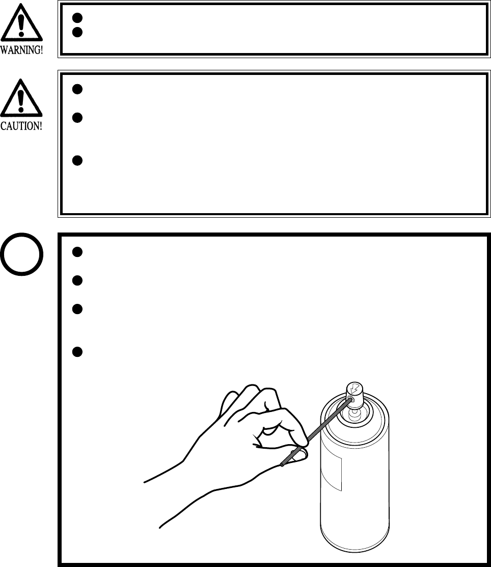
50
9 - 4 GREASING
Grease is inflammable and must never be close to fire.
Grease does harm to your body if you aspirate it. Do not perform any work
related to grease in a location where ventilation is insufficient.
If grease adheres to your skin or enters an eye, immediately rise with clean
water.
If you feel out of sorts while you are performing the work, immediately stop it
and keep quiet in a well-ventilated area. If you do not recover, consult with a
doctor.
Do not eat grease. Should you eat it, you may have loose bowels or feel like
vomiting.
Should somebody swallow it, immediately have his or her illness diagnosed
by a doctor, without compelling him or her to vomit the grease.
Be sure to use the designated type of grease. If a non-designated type grease is
used, components may break.
The period for greasing specified herein is a standard. Apply greasing to the
specified portions as occasion arises.
Do not apply greasing to places other than those specified. Greasing to
undesignated places can cause malfunctioning and the qualitative
deterioration of parts.
Do not grease any portions other than the specified ones. Use an extension
tube annexed to spray grease.
STOP
IMPORTANT
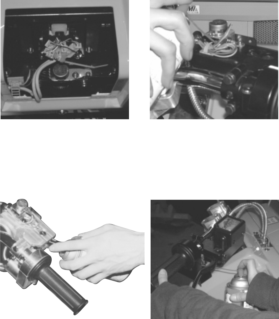
51
Once every 3 months, apply greasing to the following places.
For greasing, use Grease Mate (P. No. 090-0066).
Handlebar Volume Control Mesh (Spring)
PHOTO 9. 4 a Front Brake Volume Control Gear Mesh
PHOTO 9. 4 b
Brake Sliding Surface
PHOTO 9. 4 c Accelerator Volume Control Mesh
PHOTO 9. 4 d
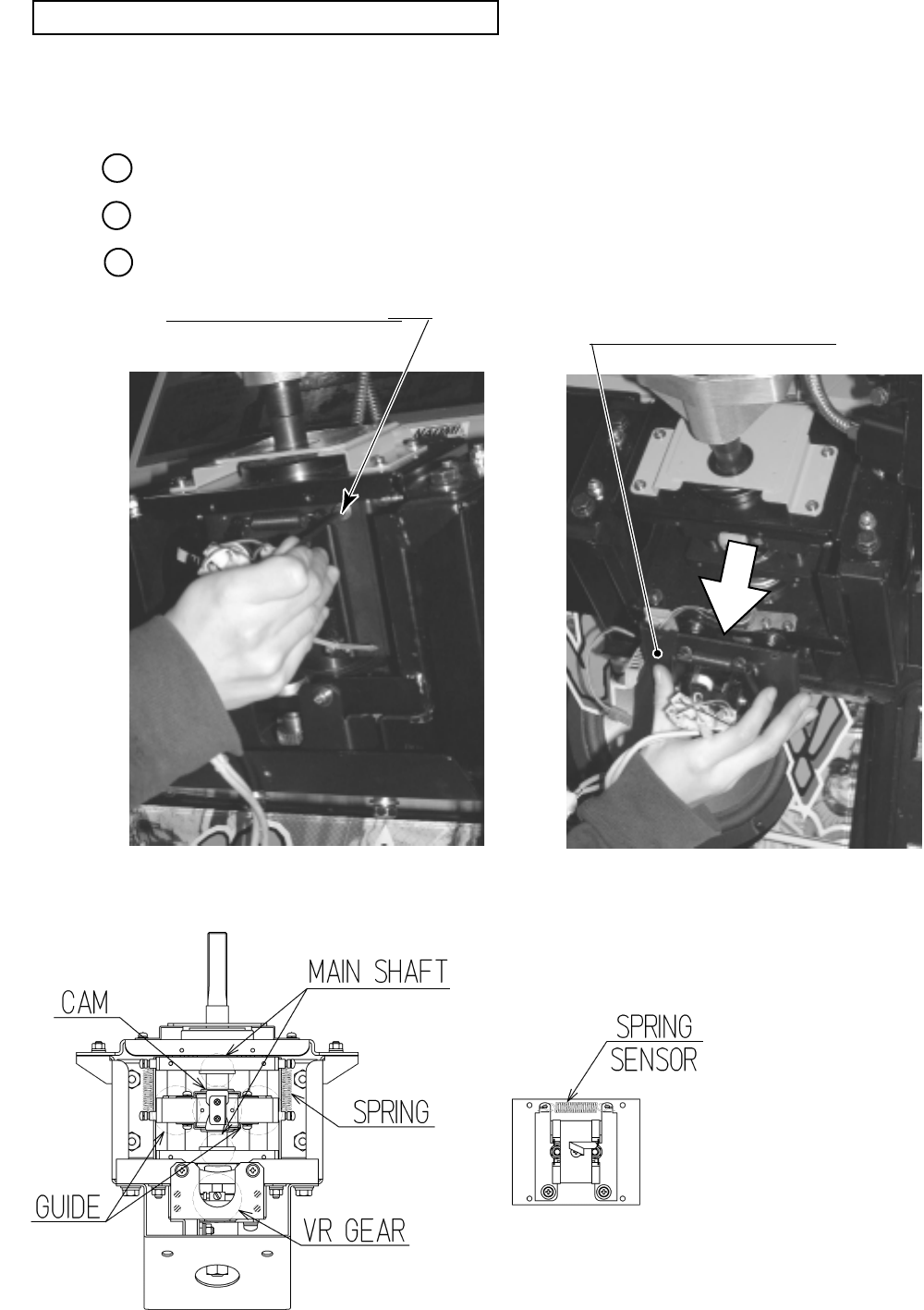
52
Greasing the handlebar mechanism requires a wrench for tamperproof screw
(for M4, accessories) and a hexagonal wrench with an opposite-side distance of 3 mm.
Remove the control panel cover (see Section 9-1).
Remove the 4 screws with hexagonal hole (PHOTO 9.4e).
Remove the ASSY centering mechanism (PHOTO 9.4f).
PHOTO 9. 4 e PHOTO 9. 4 f
FIG. 9. 4
HEXAGON SOCKET SCREW (4)
M4 X 10, flat & spring washers used.
Bearing part
Do not get the light receiving/
emitting face contaminated.
GREASING THE HANDLEBAR MECHANISM
1
2
3
ASSY CENTERING MECHANISM
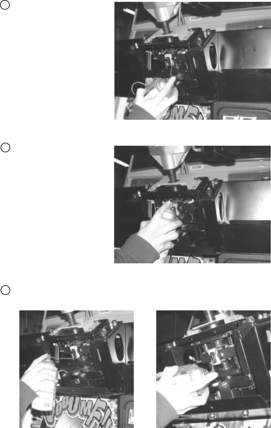
53
Grease the sliding surface of the
cam (PHOTO 9.4g).
Grease a total of 4 springs (at the
left and right) (PHOTO 9.4h).
PHOTO 9. 4 g
PHOTO 9. 4 h
Grease the slide surfaces of the handlebar shaft and the left and right shafts (PHOTO 9.4i, j).
PHOTO 9. 4 i PHOTO 9. 4 j
5
4
6
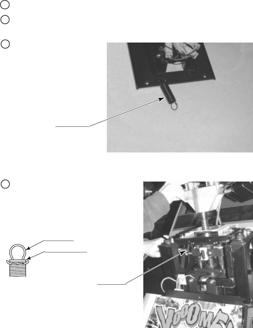
54
9 - 5 REPLACING THE SPRING
The mechanism that returns the handlebar to the direction of going straight ahead uses one
HOLD spring. The mechanism that returns the handlebar to the regular position uses 4 SUS
springs. If one of the springs has failure such as deformation, the operability will be
unsatisfactory. If so, use the following procedure to replace the spring with a spare.
The replacement requires a wrench for tamper proof screw (for M4, accessories), a hexagonal
wrench with an opposite-side distance of 3 mm, and a pair of pliers.
While holding the HOLD spring
with the pliers, release the hooks
located at both ends of the spring
(PHOTO 9.5a).
The handlebar mechanism has a round hole on
each of the left and right sides. Insert the pliers
into the round hole, hold the SUS spring, and
release the hook of both ends of the spring
(PHOTO 9.5b).
Remove the control panel cover (see Section 9-1).
Remove the 4 screws with hexagon hole, and then remove the ASSY centering mechanism
(see Section 9-4).
SPRING HOLD
WRD-2105
SPRING SUS
WRD-2010
PHOTO 9. 5 a
PHOTO 9. 5 b
HOOK PART
Wound 2 to 3 times.
Do not let the hook part at both ends
(made of SUS material) shift beyond the
position where the number of winding is 2
to 3 wounds from the end.
1
2
3
4
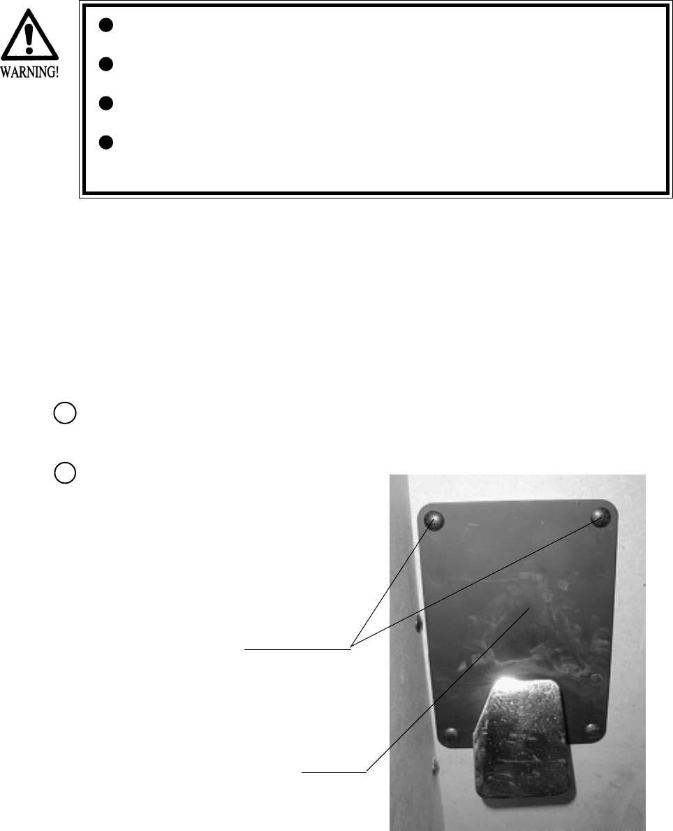
55
If the operability of the brake pedal is poor or execution of the VOLUME ADJUSTMENTS in
Test mode has no effect, adjust the volume control gear mesh or replace the volume control.
In this product, when the Pedals are fully stepped on, if the Volume shaft is rotating within the
movable range, the Volume is not feared to be damaged. Secure the Volume in the manner the
Volume Shaft is oriented as shown and the gears are appropriately engaged when the Pedals are
not stepped on.
Before starting to work, ensure that the Power SW is OFF. Failure to observe
this can cause electric shock or short circuit.
Use care so as not to damage wirings. Damaged wiring can cause electric
shock or short circuit.
Do not touch undesignated places. Touching places not designated can cause
electric shock or short circuit.
This work should be performed by the Location's Maintenance Man or
Serviceman. Performing work by non-technical personnel can cause electric
shock hazard.
10. REAR BRAKE
Take out the 4 Truss screws and remove the
Floor Lid. (PHOTO 10.1a)
10 - 1 REMOVING THE BRAKE UNIT
Turn power OFF by using the Main SW of AC Unit, or SUB PWR SW inside the SERVICE
DOOR.
CARRIAGE BOLTS
FRONT LID
PHOTO 10. 1 a
1
2
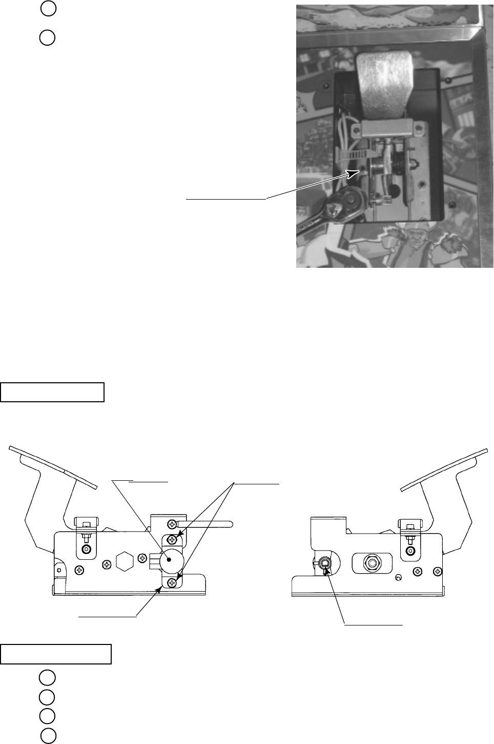
56
Disconnect the connector.
Remove the 6 hexagon nuts, and disengage the
brake unit from the ASSY Floor
(PHOTO 10.1b).
PHOTO 10. 1 b
HEXAGON NUT (6)
M6, spring washer used.
10 - 2 ADJUSTING / REPLACING THE REAR BRAKE VOLUME
Loosen the 2 screws, move the VR Bracket, and adjust the angle and appropriateness of gear
mesh.
ADJUSTMENT
REPLACEMENT
Take out the 2 screws and remove the Volume together with the VR Bracket.
After replacing the Volume, engage the gears at the angle shown, and fix the VR Bracket.
Install the Brake Unit and connect the Connector.
Turn power ON and set the Volume value in the test mode.
Adjusting or replacing the volume controls requires a Phillips screwdriver (for M4 screw), a
hexagonal wrench with an opposite-side distance of 1.5 mm, nippers, the master key, a solder
iron, and solder.
FIG. 10. 2
SCREW (2)
M4 X 8, w/flat & spring washers
VR BRACKET
VOLUME
220-5373
220-5484
"D"CUT FACE
3
4
1
2
3
4
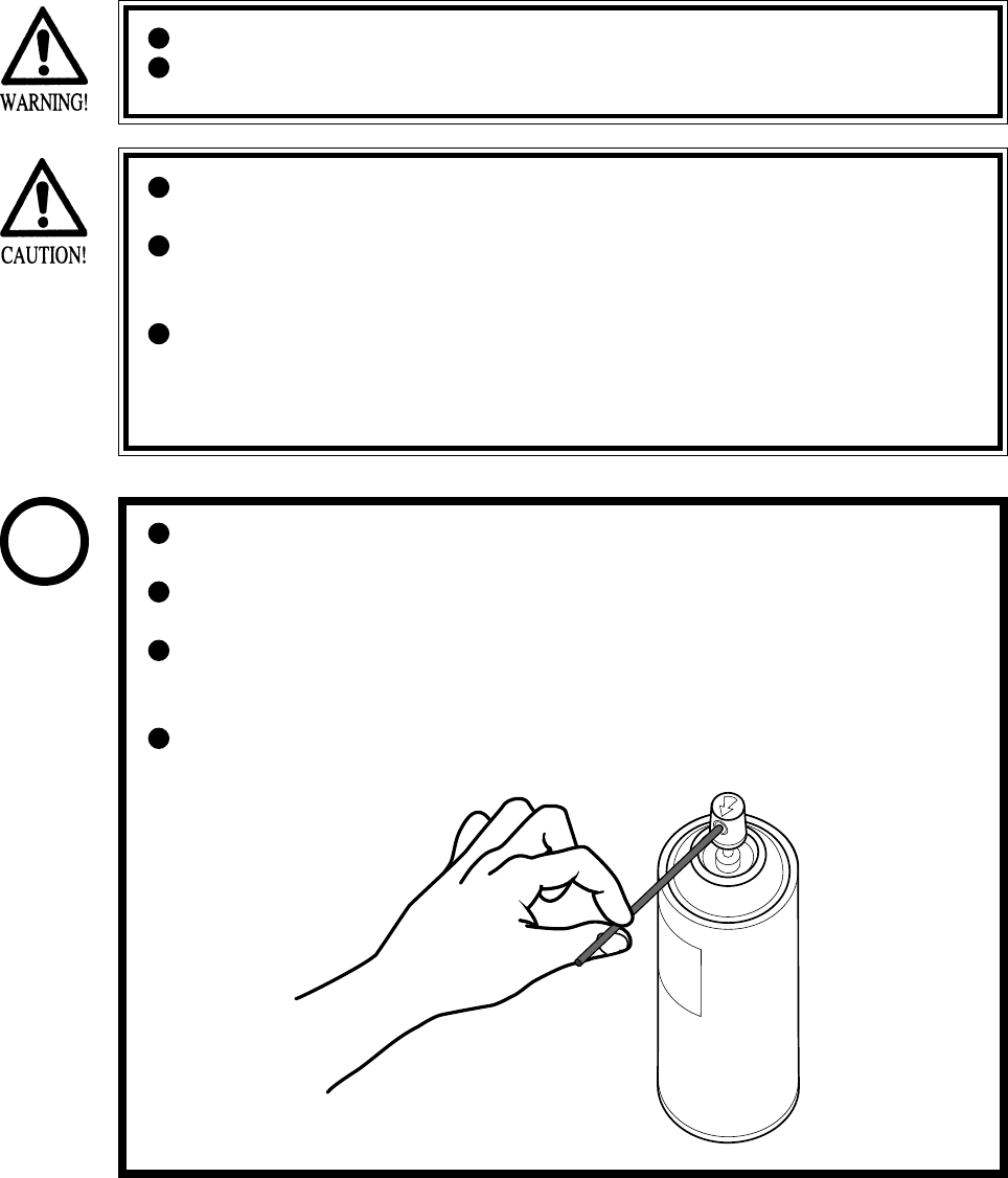
57
10 - 3 GREASING
Grease is inflammable and must never be close to fire.
Grease does harm to your body if you aspirate it. Do not perform any work
related to grease in a location where ventilation is insufficient.
If grease adheres to your skin or enters an eye, immediately rise with clean
water.
If you feel out of sorts while you are performing the work, immediately stop it
and keep quiet in a well-ventilated area. If you do not recover, consult with a
doctor.
Do not eat grease. Should you eat it, you may have loose bowels or feel like
vomiting.
Should somebody swallow it, immediately have his or her illness diagnosed
by a doctor, without compelling him or her to vomit the grease.
Be sure to use the designated type of grease. If a non-designated type grease is
used, components may break.
The period for greasing specified herein is a standard. Apply greasing to the
specified portions as occasion arises.
Do not apply greasing to places other than those specified. Greasing to
undesignated places can cause malfunctioning and the qualitative
deterioration of parts.
Do not grease any portions other than the specified ones. Use an extension
tube annexed to spray grease.
STOP
IMPORTANT
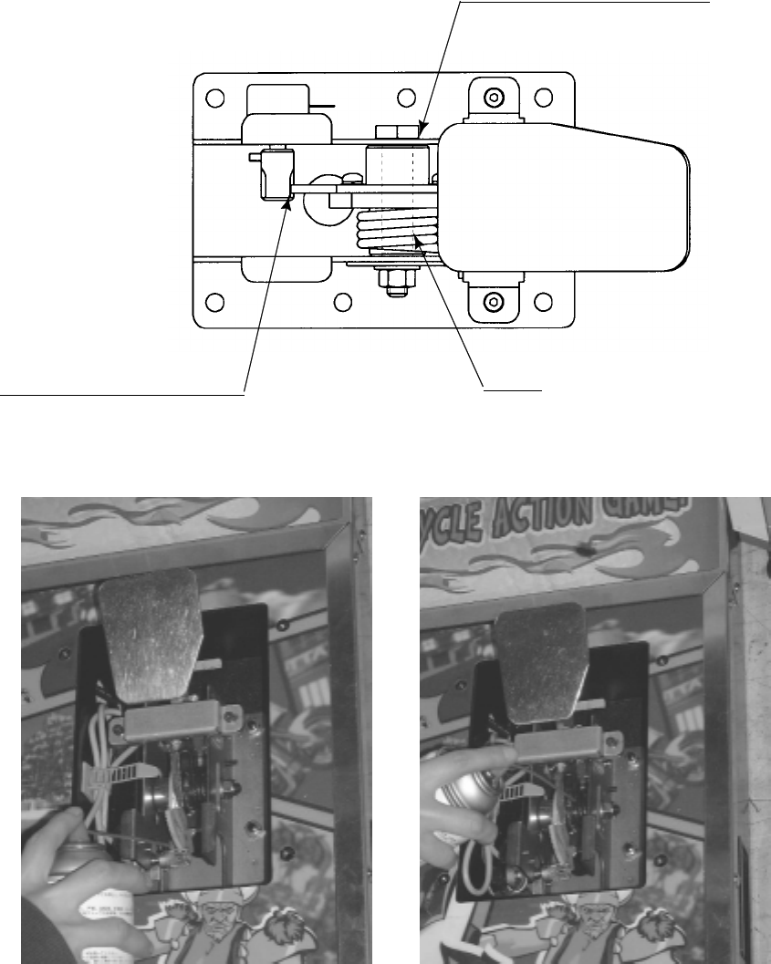
58
SPRING
FIG. 10. 3
VOLUME GEAR MESH PORTION
SLIDING FACE OF PEDAL SHAFT
Apply greasing to gear mesh portions once every 3 months.
Use GREASE MATE (SEGA PART NO. 090-0066).
PHOTO 10. 3
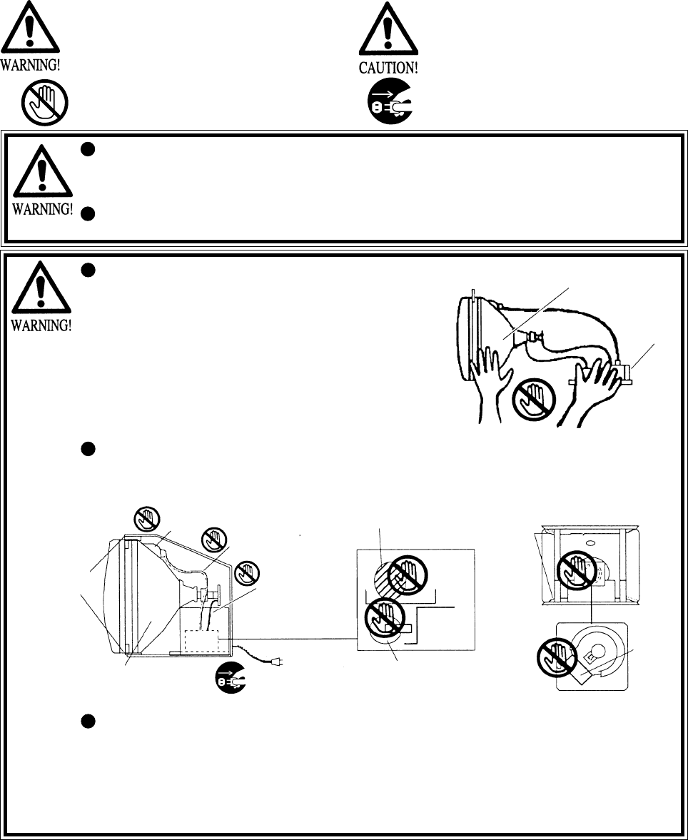
59
Primary side and Secondary side
The monitor's circuit which is divided into the Primary side
and Secondary side, is electrically isolated. Do not touch the
primary side, or do not touch both the primary side and the
secondary side simultaneously. Failing to observe the
instruction can cause electric shock and this is very
dangerous. When making monitor adjustments, use a non-
conductive driver and make adjustment without touching any
part other than the Adjustment V. R. and knob. Also, be sure
not to cause a short-circuit to the Primary side and Secondary
side. If short-circuited, it can cause electric shock or
malfunctioning, which is very dangerous.
High-tension Voltage
Some of the parts inside monitor are subject to high-tension voltage in excess of 20,000 volts and
very dangerous. Therefore, do not touch the monitor interior. Should soldering & paper wastes,
etc. be mixed in the monitor interior, turn the power off so as not to cause malfunctioning or fire
hazard.
SECONDARY SIDE
(Chassis, CRT)
ANODE LEAD
Approx. 29 kV MAIN BD
FBT Approx.
29 kV
ANODE CAP
FOCUS LEAD
(black)
Approx. 10 kV
SECONDARY SIDE
(Chassis, sheet metal work, CRT, etc.) Disconnect or unplug
NECK PCB
Approx.
10 kV
REAR PART
PRIMARY SIDE
Connecting the CRT and PCB
For combining the CRT and PCB, use the specified part No. to maintain the status of adjustments
made at the factory. The anode of the CRT itself will be accumulatively charged as time elapses,
generating high-tension voltage which is very dangerous. The monitor should be used with the
Chassis, CRT and PCB assembled. When repair, etc. is required at the time of malfunctioning,
be sure to send it in an "as is assembled" condition. If these are disassembled, what's charged to
said high tension voltage can be discharged, causing a very hazardous situation. Therefore, under
no circumstances should it be disassembled.
When performing such work as installing and removing the monitor, inserting and disconnecting
the external connectors to and from monitor interior and the monitor, be sure to disconnect the
power connector (plug) before starting the work. Proceeding the work without following this
instruction can cause electric shock or malfunctioning.
Using the monitor by converting it without obtaining a prior permission is not allowed. SEGA
shall not be liable for any malfunctioning and accident caused by said conversion.
11 - 1
CAUTIONS AND WARNINGS CONCERNING THE SAFETY FOR HANDLING THE MONITORS
11. MONITOR
Before handling the monitors, be sure to read the following explanations and comply with the
caution/warning instructions given below. Note that the caution/warning symbol marks and
letters are used in the instructions.
Indicates that handling the monitors by
disregarding this caution may cause a
potentially hazardous situation, which could
result in personal injury and or material
damage.
Indicates the instruction to disconnect a
power connector or to unplug.
Indicates that handling the monitors
erroneously by disregarding this warning may
cause a potentially hazardous situation,
which could result in death or serious injury.
Indicates that access to a specific part of the
equipment is forbidden.
PRIMARY
SIDE
DEMAGNETIZER
COIL
DEMAGNETIZER
COIL

60
Static Electricity
Touching the CRT surface sometimes causes you to slightly feel electricity. This is because the
CRT surfaces are subject to static and will not adversely affect the human body.
Installation and removal
Ensure that the Magnetizer Coil, FBT (Fly-Back Transformer), Anode Lead and Focus Lead are
not positioned close to the sheet metal work's sharp edges, etc. and avoid damaging the insulated
portions so as not to cause electric shock and malfunctioning. (For the name of parts, refer to the
above Figures).
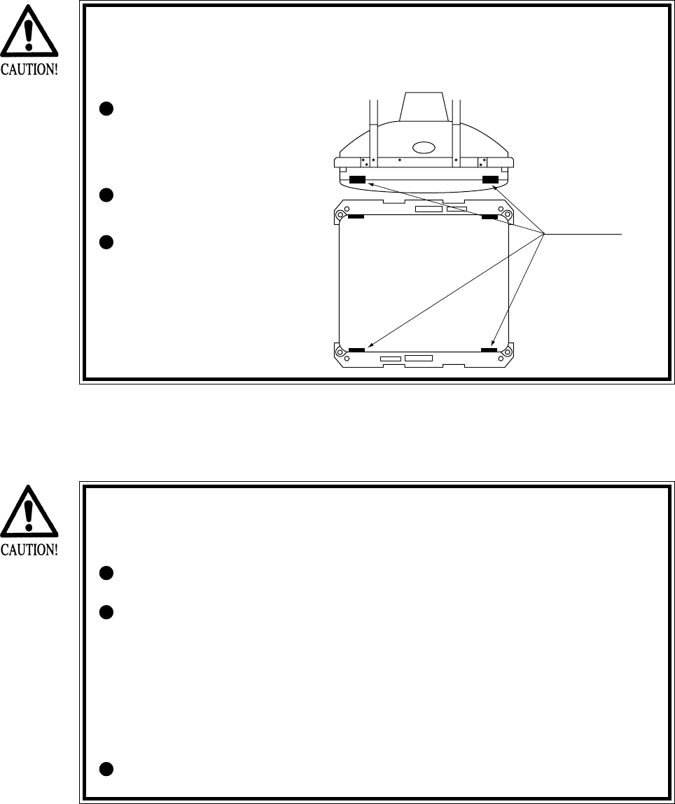
61
For the purpose of static prevention, special coating is applied to the CRT face of
this product. To protect the coating, pay attention to the following points.
Damaging the coating film can cause electric shock to the customers.
Aluminum Foil
Do not apply or rub with a
hard item (a rod with
pointed edge, pen, etc.) to
or on the CRT surfaces.
Avoid applying stickers,
seals, etc. on the CRT face.
Do not remove aluminum
foils from the CRT corners.
Removing the aluminum
foils can cause static
prevention effects to be
lowered.
11 - 2 CAUTIONS TO BE HEEDED WHEN CLEANING THE CRT SURFACES
Static preventive coating is applied to the CRT surfaces. When cleaning, pay
attention to the following points. Peeling off of static preventive coat can cause
electric shock.
Remove smears by using a dry, soft cloth (flannels, etc.). Do not use a coarse
gauze, etc.
For smear removing solvent, alcohol (ethanol) is recommended. When using
chemical detergent, be sure to follow instructions below:
• Dilute chemical detergent with water and dip a soft cloth in and then
thoroughly wring it to wipe smears off.
• Do not use a chemical detergent containing an abradant, powder or bleaching
agent.
• Do not use alkaline chemical detergents such as "glass cleaner" available on
the market or solvents such as thinner, etc.
Do not rub or scratch the CRT face with hard items such as brushes, scrub
brush, etc.
Clean the CRT surfaces once a week. When cleaning, pay attention to the above caution so that
the antistatic coating will not come off.
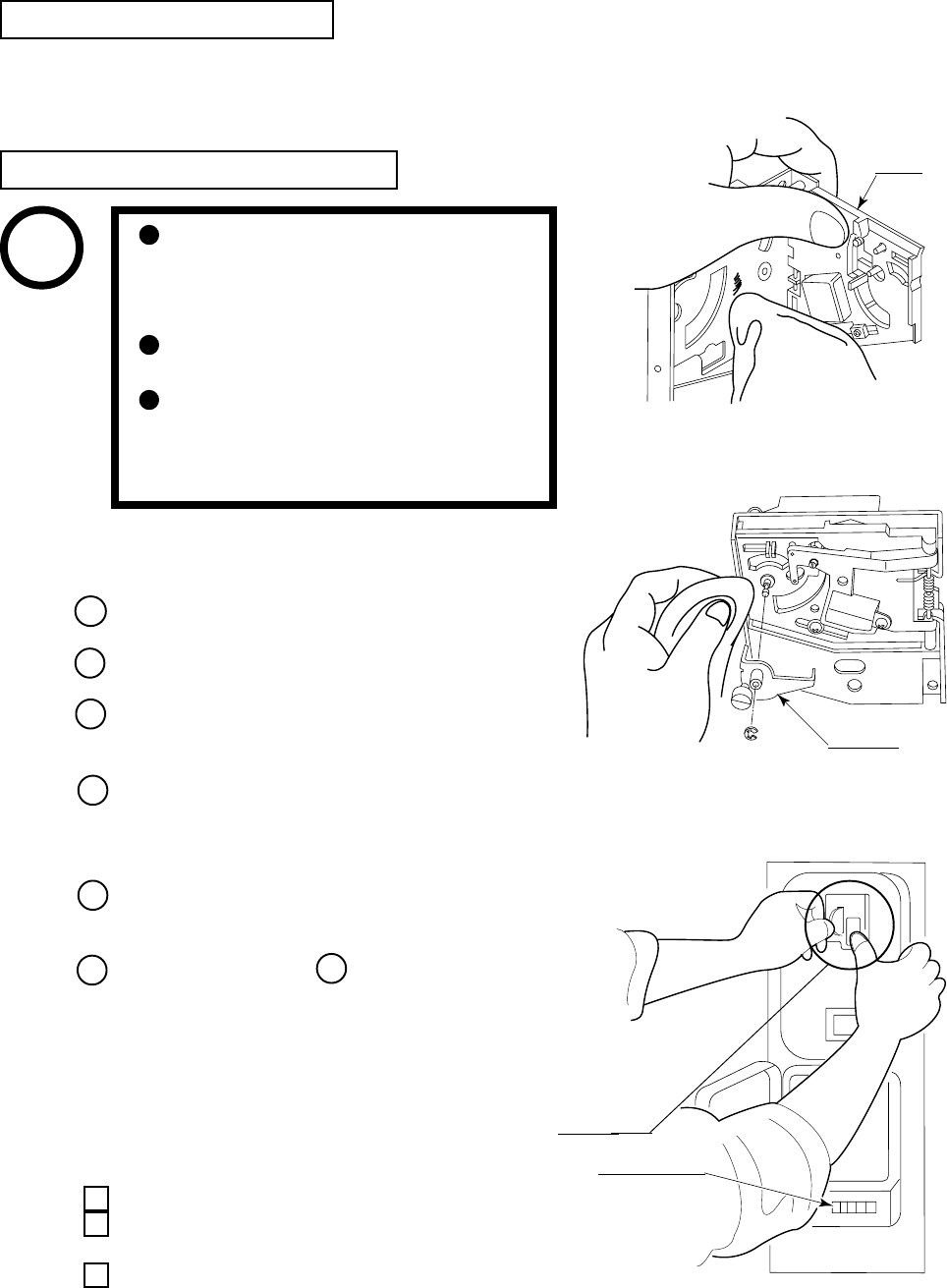
62
FIG. 12 b
CRADLE
12. COIN SELECTOR
The coin selector should be cleaned once every
3 months. When cleaning, follow the procedure
below:
Turn the power for the machine OFF. Open the
coin chute door.
Open the gate and dust off by using a soft brush
(made of wool, etc.).
Remove and clean smears by using a soft cloth
dipped in water or diluted chemical detergent
and then squeezed dry.
Remove the CRADLE.
When removing the retaining ring
(E ring), be very careful so as not to bend the
rotary shaft.
Remove stain from the rotary shaft and shaft
receiving portions by wiping off with a soft
cloth, etc.
After wiping off as per above, further apply
a dry cloth, etc. to cause the coin selector to dry
completely.
CLEANING THE COIN SELECTOR
COIN INSERTION TEST
Once every month, when performing the
Coin SW Test, simultaneously check the
following:
Does the Coin Meter count satisfactorily?
Does the coin drop into the Cashbox
correctly?
Is the coin rejected when inserted while
keeping the Reject Button pressed down?
Remove and clean smears by using a
soft cloth dipped in water or diluted
chemical detergent and then
squeezed dry.
Never apply machine oil, etc. to the
Coin Selector.
After cleaning the Coin Selector,
insert a regular coin in the normal
working status and ensure that the
Selector correctly functions.
FIG. 12 a
FIG. 12 c
GATE
Insert a coin
while keeping the
Reject Button
pressed down and
check if it is
rejected.
COIN METER
If the coin is not rejected when the REJECT button is pressed, open the coin chute door and
open the selector gate. After removing the jammed coin, put a normal coin in and check to see
that the selector correctly functions.
HANDLING THE COIN JAM
STOP
IMPORTANT
1
2
3
4
5
65
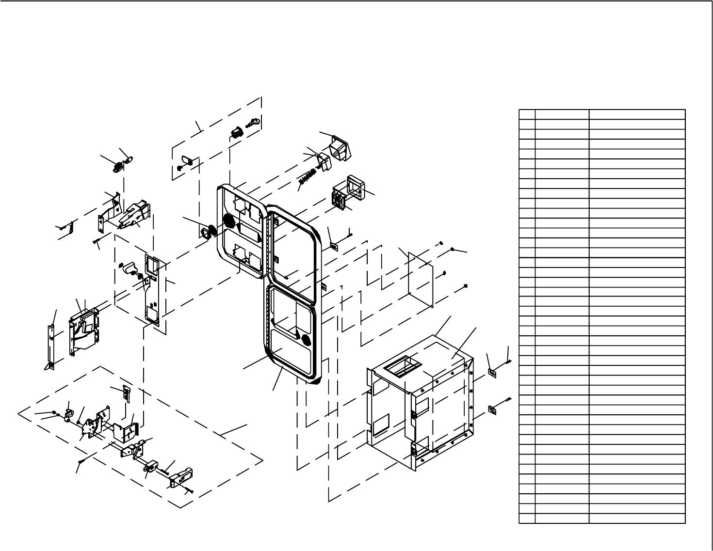
63
D
K
5
L
C
G
H
M
E
A
24
18
29
J
F
B
5
1
28
17
25
14
27
21
19
22
12
20
16
23
13
11
3
24C REJECT CUP SIDE PLATE891-1105-01
29
28
27
26
25
24M
24L
24K
24J
24H
24G
24F
24E
24D 891-1106-00
891-1107-00
891-1110-00
891-1116-16
891-1125-00
892-1002-07
892-1002-08
892-1002-09
892-1002-11
891-0604-16
891-0614-16
892-1002-01
892-1002-021
892-1002-10 BRACKET, HOLD DOWN
BRACKET, COVERSIDE
BRACKET, LAMPSIDE
MINI DOOR W/DBV C/O
MINI DOOR 2 ENTRIES
SCREW, PAN HEAD
SLEEVE, SNAP-ON
ELASTIC SNAP NUT
CLIP, SNAP-ON
COVER, PLASTIC
MICROSWITCH, BLACK - MED.
ADJUSTER, COIN
BRACKET, MICROSWITCH
REJECT CUP BASE PLATE
LAMP WEDGE BASE 6 VOLT
14
24
24B
24A
23
22
21
20
19
18
17
16
15
13 891-0100-4016
891-1008-107
891-1113-03
891-1113-011
891-1117-00
891-1118-00
891-1121-00
891-1311-16
891-1312-16
891-1109-16
020X1877-005
890-1007-00
891-2216-16
890-1206-02
BASE PLATE ASSEMBLY
KEP NUT
SCREW,FLAT HEAD M/S
MICROSWITCH ASSEMBLY
NUT KEPS #8-32 X 5/16 HEX
REJECT FLAP
REJECT BEZEL, NYLON
BUTTON BEZEL, NYLON
SPRING, E/R BUTTON
LAMPHOLDER
E/R BUTTON US $1 COIN RIGHT
E/R BUTTON US 4x25c/$1 LEFT
COVER PLATE
11
12
10
9
8
7
6
5
4
3
2
1
#
W.G. PART #
812-4150-011
812-4050-011
890-1002-00
890-1003-00
890-1017-00
890-1019-00
890-1300-00
891-0514-00
025X3711-001
025X3712-001
891-0509-162
891-0547-00
DOUBLE FRAME
METAL CASHBOX
ENCLOSURE W/CHUTE
CLAMP UK 5/8" CABINET
KEYHOOK
WASHER INTERNAL TOOTH 3/4"
SCREW TRILOBULAR
CLAMP SCREW
HINGE SCREW
S-10 US $1 COIN MECH RIGHT
S-7 US 25c COIN MECH LEFT
DESCRIPTION
6
2
9
4
8
10
5
7
26
84
15
LOCK SINGLE BIT
WELLS-GARDNER
2701 N. KILDARE CHICAGO, IL 60639
2 ENTRIES WITH BILL
OVER/UNDER MINI DOOR
VALIDATOR BOTTOM DOOR
WGD15-2110-01
& SPECIAL ENCLOSURE
1-800-336-6630
ELECTRONICS CORPORATION
WWW.WGEC.COM
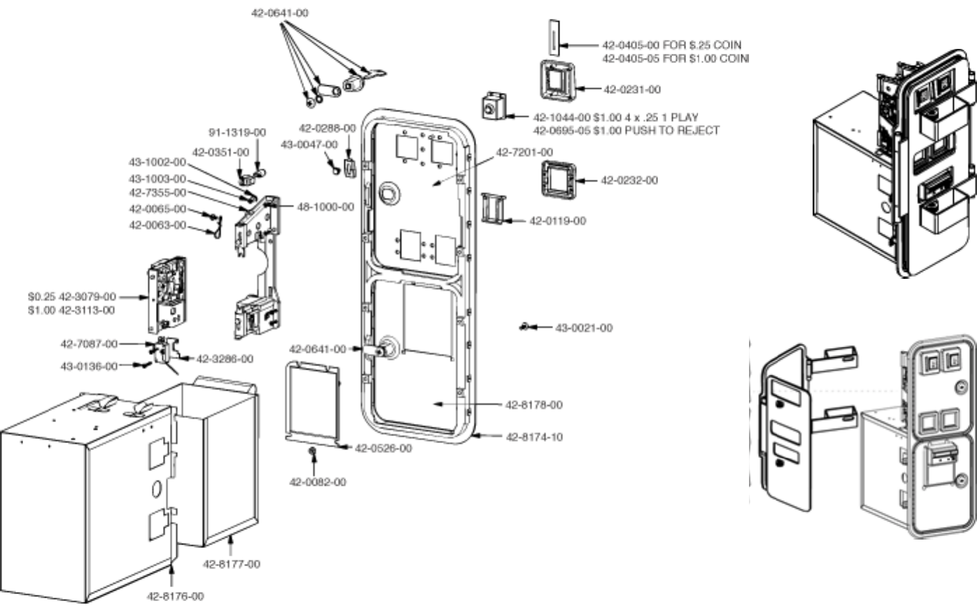
64
Tom Happ Ph: 847-593-6161 ext. 107
tom.happ@happcontrols.com Fx: 847-956-2091
Happ Controls, 106 Garlisch Drive, Elk Grove, IL 60007
Visit our website http://www.happcontrols.com
Guardian Hasp
30-2400-200
65
OPTIONAL DOLLAR BILL ACCEPTOR
THE COIN DOOR ASSEMBLY USED ON WILD RIDER STD COMES
EQUIPPED TO ACCEPT A DOLLAR BILL ACCEPTOR. ALL NEEDED WIR-
ING CONNECTIONS ARE CONVIENENTLY LOCATED INSIDE THE GAME
FOR THIS APPLICATION.
THE COIN DOOR CAN ACCCOMMODATE THE FOLLOWING
VALIDATOR(S):
FORWARD-MOST Mars 2000 series
HOLE POSITION
**42-1155-00 MARS VALIDATOR $1, 2, 5 300 CAP
The frame and cashbox enclosure on this coindoor has been modified to accomodate
a Mars 2000 series upstacker. A 2000 series stacker can be added by simply remov-
ing the cut-out plate. This one entry door can be ordered through Happ Controls or
one of Happ Controls authorized distributors. The part number is 40-6000-10EX.
The Mars stacker can be obtained through an autherized Mars distibutor.
**Happ part number
Note: Your game may have either Happ Controls Coin Door Assembly or the Wells
Gardner Coin Door Assembly (not shown).
Security Locking Bar/Bracket Set Part No.# 999-0966
Modified Cash Box (For use when DBA installed)
Part No. # 999-1106
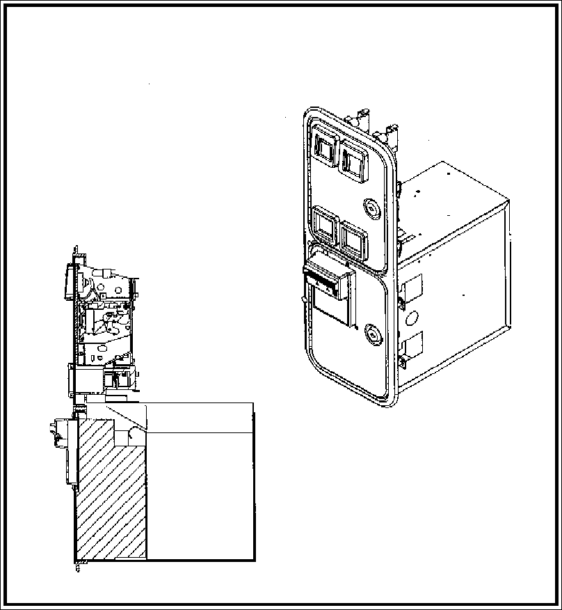
66
**Coin door shown with optional dollar bill validator inserted**
67
The items listed below require periodic check and maintenance to retain the performance of this
machine and to ensure safe business operation.
13. PERIODIC INSPECTION TABLE
Be sure to check once a year to see if Power Cords are damaged, the plug is
securely inserted, dust is accumulated between the Socket Outlet and the
Power Plug, etc. Using the product with dust as is accumulated can cause fire
and electric shock hazards.
Periodically once a year, request the place of contact herein stated or the
Distributor, etc. where the product was purchased from, as regards the internal
cleaning. Using the product with dust as is accumulated in the interior
without cleaning can cause a fire or accident. Note that cleaning the interior
parts can be performed on a pay-basis.
CLEANING THE CABINET SURFACES
When the cabinet surfaces are badly soiled, remove stains with a soft cloth dipped in water or
diluted (with water) chemical detergent and squeezed dry. To avoid damaging surface finish, do
not use such solvents as thinner, benzine, etc. or abrasives, bleaching agent and chemical
dustcloth.
Item Interval Reference
CABINET
Check Adjusters'contact with surface.
Daily 2
CONTROL PANEL Check lamps. Monthly 8-3
Check VOLUME value. Monthly 8-3
Greasing Trimonthly 9-4
REAR BRAKE Check VOLUME value. Monthly 8-3
Greasing Trimonthly 10-3
MONITOR Check adjustments.
Monthly or when moving.
5,8-2,11
Cleaning of CRT surfaces. Weekly 11-2
COIN SELECTOR Check COIN SW. Monthly 8-2
Coin insertion test. Monthly 12
Cleaning of COIN SELECTOR. Trimonthly 12
GAME BD MEMORY TEST. Monthly 5,8-2
Check settings. Monthly 5,8-2,8-3
Cabinet surfaces Cleaning As necessary. See below.
INTERIOR Cleaning Annually See above.
POWER SUPPLY PLUG Inspection and cleaning
TABLE 13
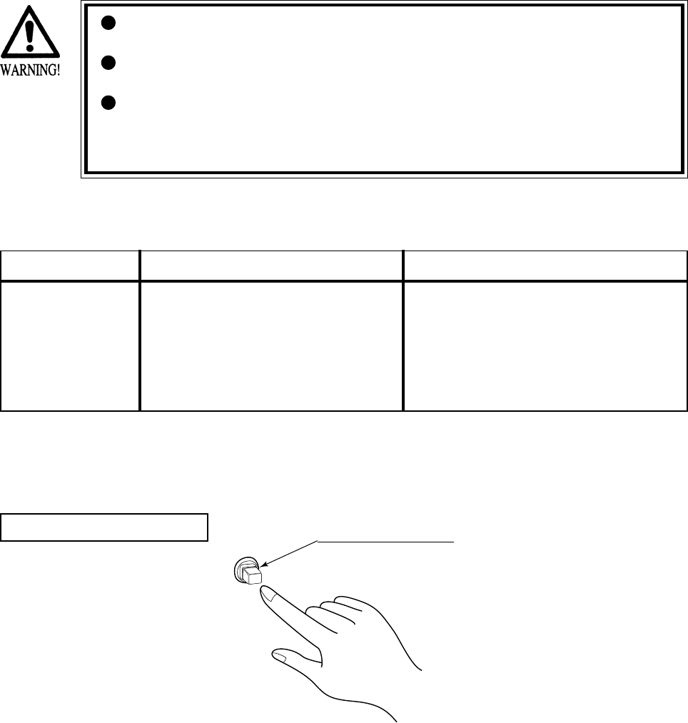
68
14 - 1 TABLE OF TROUBLESHOOTING
14. TROUBLESHOOTING
In order to prevent electric shock and short circuit hazards, be sure to turn
power off before performing work.
Be careful so as not to damage wirings. Damaged wiring can cause electric
shock or short circuit.
After removing the cause of the functioning of the Circuit Protector, reinstate
the Circuit Protector. Depending on the cause of the functioning, using the
Circuit Protector as is without removing the cause can cause generation of
heat and fire hazard.
In case a problem occurs, first check wiring connector connections.
CIRCUIT PROTECTOR
Functions due to the activation of
bimetal. To restore the function,
wait for approximately one minute
or longer until the bimetal cools
off. (Press the Button.)
CIRCUIT PROTECTOR
TABLE 14. 1 a
When the main SW is
turned ON, the
machine is not
activated.
The power is not ON.
Incorrect power source/voltage.
The CIRCUIT PROTECTOR functioned
due to momentary overcurrent.
Firmly insert the plug into the outlet.
Make sure that the power supply/voltage are
correct.
After eliminating the cause of overload, have
the Circuit Protector of the AC Unit restored .
PROBLEMS CAUSE COUNTERMEASURES
FIG. 14. 1

69
The color on the
screen is not correct.
The on-screen image
of the monitor sways
and or shrinks.
The image is
displayed, but the
Billboard does not
light up.
Sound is not emitted.
Sounds from
Speakers and
Woofer are not
emitted.
Operation is
unsatisfactory.
Make appropriate adjustments.
Make sure that the power supply/voltage are
correct.
Secure sufficient power capacity.
Check the connection of the connector
(see 1 , Sec. 5).
Adjust the SWITCH UNIT's sound adjustment
volume (control) (8-1).
Perform sound and memory test (8-2).
Perform Volume setting. (8-3)
Adjust or replace the V. R. (see Sec. 9, 10).
Adjust GEAR mesh (see Sec. 9, 10).
Replace the spring.
Incorrect monitor adjustment.
Incorrect power source/voltage.
In sufficient power capacity.
Connection failure between Cabinet and
Billboard
Fluorescent Lamp needs replacement.
Sound volume adjustment is not correct.
Sound related Board and Memory are
irregular.
Poor V. R. setting.
V. R. deviation or malfunctioning.
Poor mesh of V.R. GEAR.
Spring failure due to secular change of
Handle, Accelerator and Brake
mechanism.
TABLE 14. 1 b
PROBLEMS CAUSE COUNTERMEASURES
70
14 - 2 ERROR MESSAGE
On the screen, the NAOMI2 Board displays errors responding to various troubles when power is
turned on or the Test mode closes. The game is not available at this time.
When an error is displayed, take action against it according to the appropriate cause and action
listed below.
Usually no error is displayed unless the settings in the System Test mode have been made
erroneously. If a component related to the NAOMI2 Board is replaced with one of another type
of game machine, an error may occur.
ERROR 01
[DISPLAY] ERROR 01
THIS GAME IS NOT ACCEPTABLE
BY MAIN BOARD.
[CAUSE] The ROM BOARD is not connected correctly to the MAIN BD.
[COUNTERMEASURES] First, turn power off, connect the ROM BD correctly. If the status is not
improved yet, the board may be malfunctioning.
ERROR 02
[DISPLAY] ERROR 02
THIS GAME IS NOT ACCEPTABLE
BY MAIN BOARD.
[CAUSE] The destination for the NAOMI2 Board and that for the ROM board are
different.
[COUNTERMEASURES] Use the main or ROM board that conforms to the destination specification
meeting the side of this product. This error cannot be avoided by changing
the settings.
ERROR 03
[DISPLAY] ERROR 03
BOARD MALFUNCTIONING.
[CAUSE] The serial ID on the main board cannot be read.
[COUNTERMEASURES] Remove the ROM board from the main body, and send only the main board
to us for repair.
ERROR 04
[DISPLAY] ERROR 04
BOARD MALFUNCTIONING.
[CAUSE] BOOT ROM program cannot read the Main Board's serial ID.
[COUNTERMEASURES] Board malfunctioning.
Ask for the repair/servicing of ROM BD and MAIN BD.
71
CAUTION 51
[DISPLAY] CAUTION 51
GAME ASSIGNMENTS ARE
INCORRECT.
SET CORRECTLY IN SYSTEM
ASSIGNMENTS OF TEST MODE.
[CAUSE] The CABINET TYPE does not match the settings required for the game.
[COUNTERMEASURES] Enter the Test mode, and change the CABINET TYPE setting of SYSTEM
ASSIGNMENTS as suitable for the game. See Section 8-2 for the suitable
setting.
CAUTION 52
[DISPLAY] CAUTION 52
CHANGE VIDEO OUTPUT OF
THIS GAME TO THE SETTING
CORRESPONDING TO HORIZONTAL
SCANNING FREQUENCY 15KHz.
[CAUSE] Though the game is specialized for use with a horizontal frequency of
15 kHz, it is operating with 31 kHz.
[COUNTERMEASURES] Set the monitor to 15 kHz, and turn on dip switch No. 1 on the NAOMI2
main board.
If your monitor is not available for 15 kHz, this game does not work on it.
CAUTION 53
[DISPLAY] CAUTION 53
CHANGE VIDEO OUTPUT OF
THIS GAME TO THE SETTING
CORRESPONDING TO HORIZONTAL
SCANNING FREQUENCY 31KHz.
[CAUSE] Though the game is specialized for use with a horizontal frequency of
31 kHz, it is operating with 15 kHz.
[COUNTERMEASURES] Set the monitor to 31 kHz, and turn off dip switch No. 1 on the NAOMI2
main board.
If your monitor is not available for 31 kHz, this game does not work on it.
CAUTION 54
[DISPLAY] CAUTION 54
GAME ASSIGNMENTS ARE
INCORRECT.
SET CORRECTLY IN SYSTEM
ASSIGNMENTS OF TEST MODE.
[CAUSE] The MONITOR TYPE does not match the settings required for the game.
[COUNTERMEASURES] Enter the Test mode, and change the CABINET TYPE setting of SYSTEM
ASSIGNMENTS as suitable for the game. See Section 8-2 for the suitable
setting.
Perform replacement between length and breadth if it is required for the
monitor.
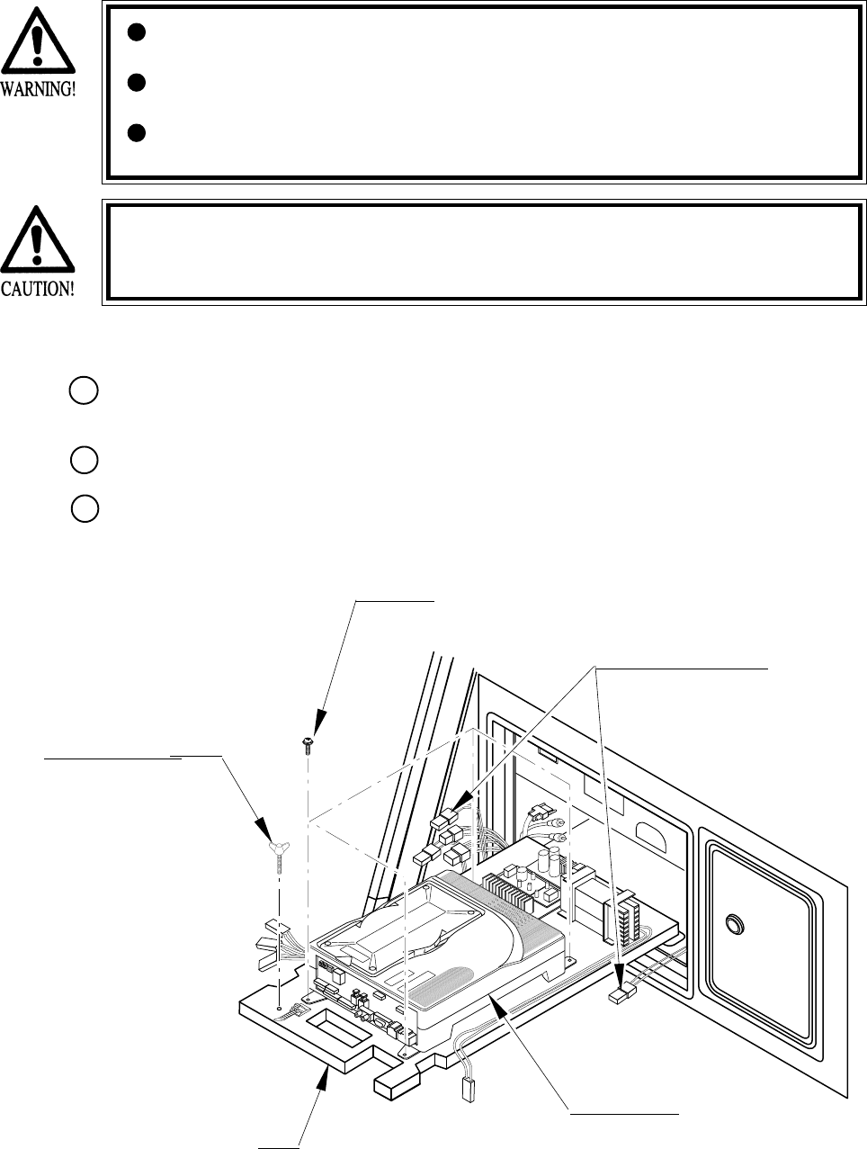
72
FIG. 15. 1 a
15. GAME BOARD
In order to prevent electric shock and short circuit hazards, be sure to turn
power off before performing work.
Be careful so as not to damage wirings. Damaged wiring can cause fire,
electric shock or short circuit.
Do not expose the Game BD, etc. without a good reason. Failure to observe
this can cause electric shock hazard or malfunctioning.
In this product, setting changes are made during the test mode. The Game BD
need not be operated. Use the Game BD, etc. as is with the same setting made at
the time of shipment so as not to cause electric shock and malfunctioning.
15 - 1 TAKING OUT THE GAME BOARD
Turn power OFF by using the Main SW of AC Unit or the SUB PWR SPLY SW inside the
SERVICE DOOR.
When the power is turned OFF with the Main SW, unlock and remove the SERVICE DOOR.
Disconnect all of the Connectors connected to the Filter Board at the front of the Shield Case,
3 Connectors on the left-hand side facing the Shield Case and the right-hand side Connector.
THUMBSCREW (1)
M4 X 25, flat washer used.
SCREW (4)
M4 X 16, w/flat & spring washers
BASE
GAME BOARD
Disconnect the Connector.
1
2
3
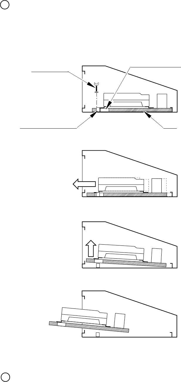
73
FIG. 15. 1 b
Take out the thumbscrew securing the Base, and remove the Base from the cabinet with the
Shield Case as is mounted. When removing the Base, first withdraw the Base towards you up to
the notch portions allowing for evading the fitting which secures the Base. From that position,
lift up and remove the Base. At this time, be very careful so as not to damage wiring.
Take out the 4 screws and remove the Shield Case.
THUMBSCREW Notch portion of BASE
BASE
Fitting to secure the BASE
Move towards you.
Lift up.
Take out.
4
5
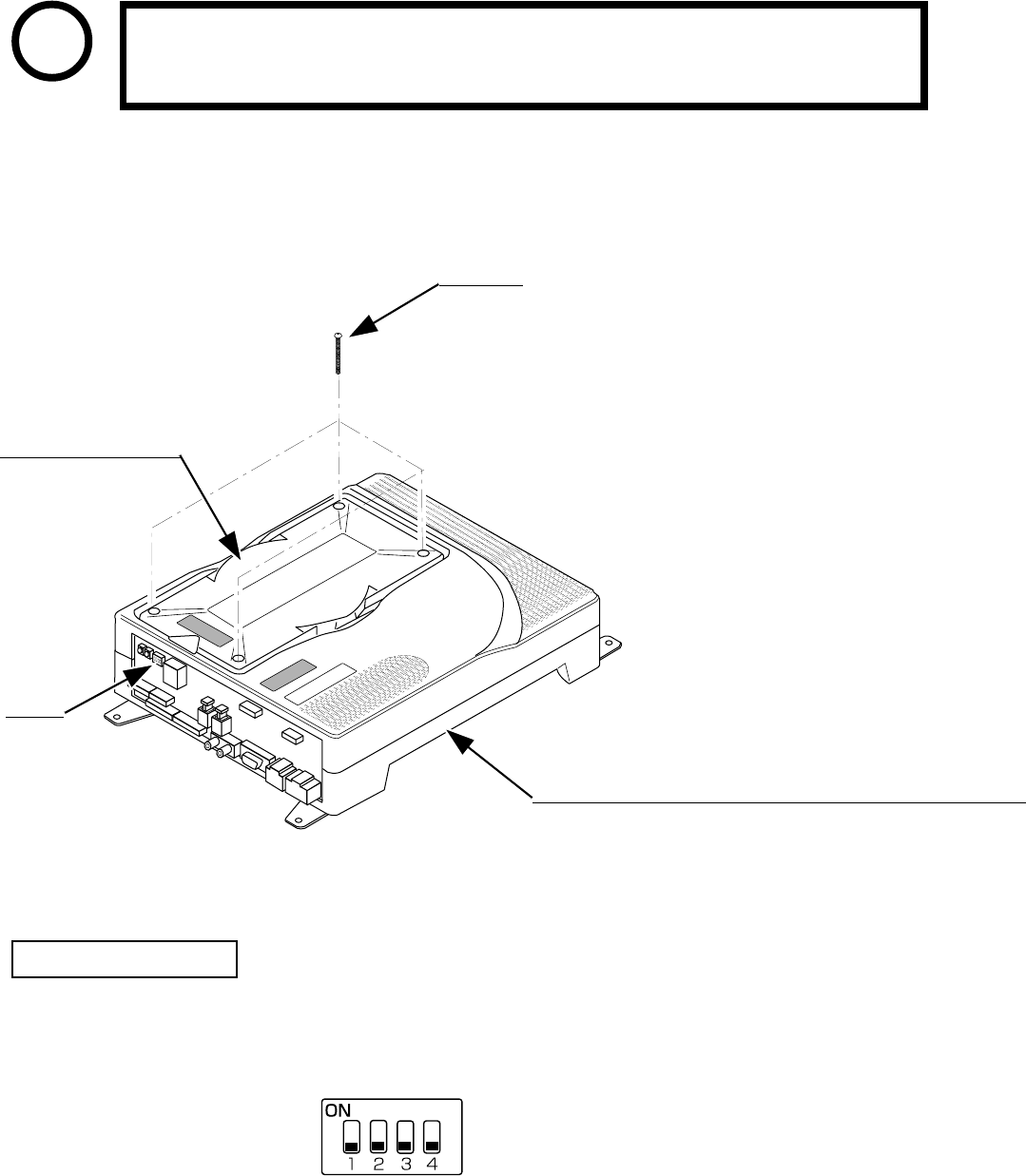
74
Ensure that the DIP SW setting is performed as designated. Failure to observe
this may cause functioning not suitable for the actual operation, or
malfunctioning.
DIP SW
ROM CASE NAO2 WRD
840-0046C
FIG. 15. 2 a
15 - 2 COMPOSITION OF GAME BOARD
STOP
IMPORTANT
ASSY CASE NAO2 WRD USA (840-0046D-01) : USA
ASSY CASE NAO2 WRD EXP (840-0046D-02) : OTHERS
ASSY CASE NAO2 WRD KOR (840-0046D-03) : KOREA
ASSY CASE NAO2 WRD AUS (840-0046D-04) : AUSTRALIA
SCREW (4)
M3 X 30, chrome plated
ASSY CASE NAOMI2 MAIN BD USA(840-0046A-01):USA
ASSY CASE NAOMI2 MAIN BD EXP(840-0046A-02):OTHERS
ASSY CASE NAOMI2 MAIN BD KOR(840-0046A-03):KOREA
ASSY CASE NAOMI2 MAIN BD AUS(840-0046A-04):AUSTRALIA
¤In the product, set all of the DIP SWes to OFF.
FIG. 15. 2 b
DIP SW SETTING
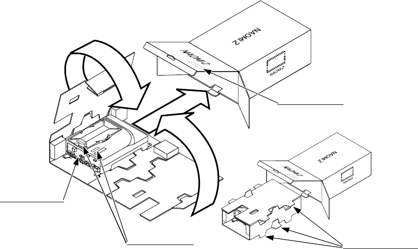
75
A
B
C
FIG. 15. 3 a
15 - 3 REPAIR/SERVICING AND CARTON BOX
When transporting NAOMI 2 for repair/servicing, follow the instructions below.
The accessory carton box is needed when transporting NAOMI 2 for repair/servicing. Be sure
to safely store the Carton Box.
• When sending for repair/servicing, remove all of the wire harnesses and cables from the
Filter BD in front.
• When transporting NAOMI 2 Main BD for the repair/servicing, ensure that the ROM BD
used is in an as is installed status.
• When sending the NAOMI 2 Main BD for repair/servicing, be sure to put it in the accessory
carton box together with the Shield Case. The Main Board (Shield Case) and carton box
have an identical serial number. When sending, ensure that the combination seral number is
identical with each other.
• When putting NAOMI 2 SHIELD CASE in the carton box, the Leg Bracket need not be
removed.
• By paying careful attention to the following Figure and the direction shown by on-Carton-
Box printing, put the Shield Case in the Carton Box.
• The projected portions of the packing material is intended for cushioning. Therefore, do not
bend the projected portions.
FILTER BOARD
Projected portions of
the packing material.
Serial No. Display
Serial No. Display
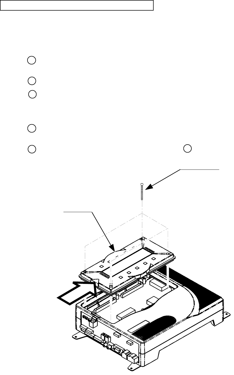
76
FIG. 15. 3 b
REMOVING AND REINSTALLING THE ROM BOARD
Ensure that the power is off before preforming work.
• REMOVING
Disconnect all of the wirings connected to NAOMI 2, and remove NAOMI 2 from inside the
cabinet.
Remove the 4 screws which secure the ROM BD Case on NAOMI 2 Case.
Remove ROM BD Case upward by holding both sides.
• INSTALLING
Make sure that the connector direction is correct, and insert the ROM BD Case fully onto
NAOMI 2 Main BD.
By using the 4 screw previously removed as per REMOVING above, secure ROM BD
Case to NAOMI 2 Case.
ROM BOARD
TRUSS SCREW (4)
M3 X 30, chrome plated
WHEN INSTALLING,
BE CAREFUL
OF THIS DIRECTION!
1
2
3
1
22
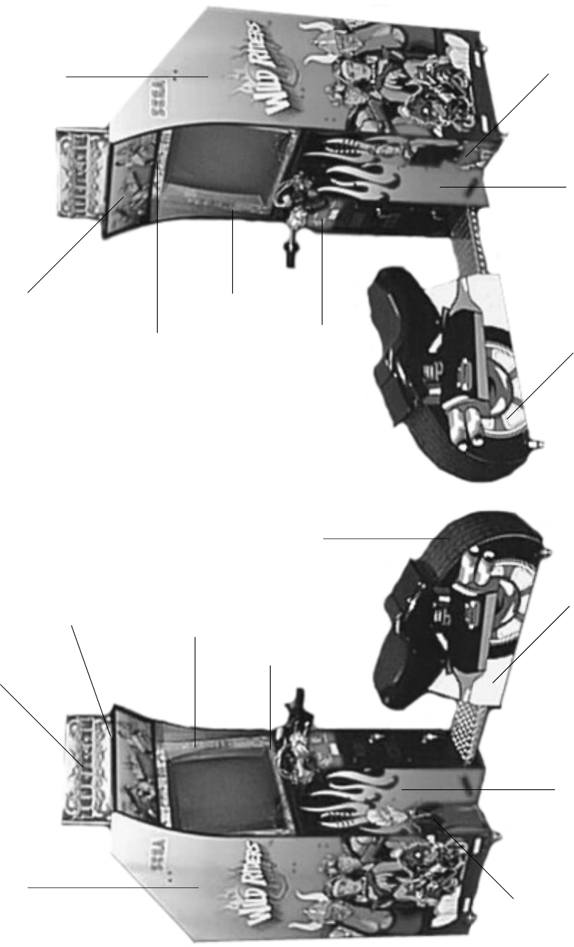
77
16. DESIGN RELATED PARTS
HOLDER POP PANEL
999-1151
DECAL BEZEL RIGHT
INSTRUCTION
999-1155
DECAL CONTROL
PANEL
999-1159
DECAL SEAT
LEFT SIDE
999-1165
DECAL CABINET
SIDE LEFT
999-1153
DECAL LEFT SIDE
COIN BOX
999-1162
DECAL FRONT
MAN
999-1160
DECAL UPPER
BONUS/GAME OVER
999-1156
POP DISPLAY
999-1150 MARQUEE
999-1152
DECAL BEZEL LEFT
INSTRUCTION
999-1158
DECAL LOWER
GETAWAY
999-1157
DECAL FRONT
WOMAN
999-1161
DECAL RIGHT SIDE
COIN BOX
999-1163
DECAL SEAT
RIGHT SIDE
999-1166
TIRE TREAD
FLAT DECAL
999-1164
DECAL CABINET
SIDE RIGHT
999-1154
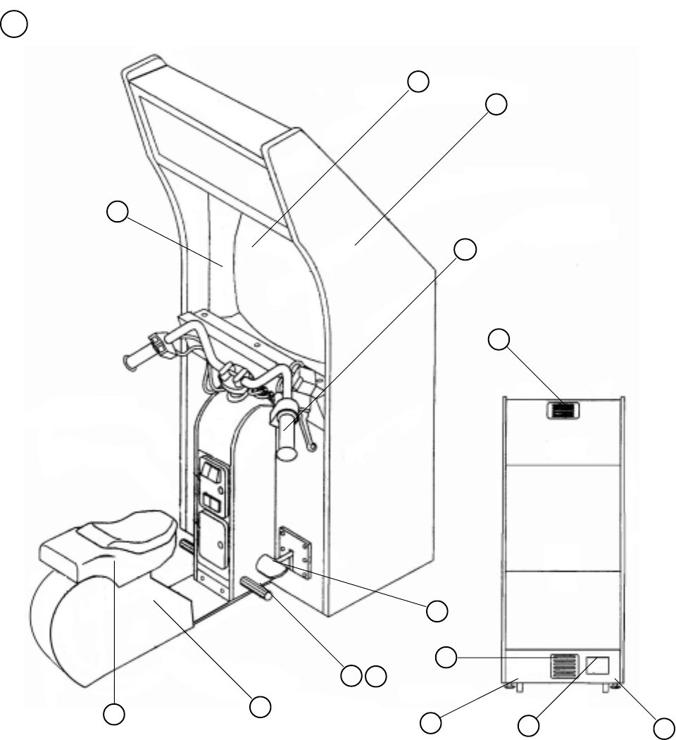
78
1 TOP ASSY WRD
17. PARTS LIST
1
2
3
4
5
6
7
8
9
10
ITEM NO. PART NO. DESCRIPTION
1 WRD-2500 ASSY HANDLE
2 CTA-1650 BRAKE UNIT
3 SEAT CABI
4 999-1167 FOOT REST
5 999-1168 VENT -4 HOLE AIR BLACK PDRCOAT
6 999-1065 VENT -8 HOLE AIR BLACK PDRCOAT
7 LOC. PURCHASE WOOFER
8 29 INCH MONITOR
9 CABINET
10 AC UNIT
11 999-1170 27” BEZEL
12 999-0169 CASTER
13 999-0167 LEG LEVELER
14 999-1169 COVER FOOT REST
11
12 13
14
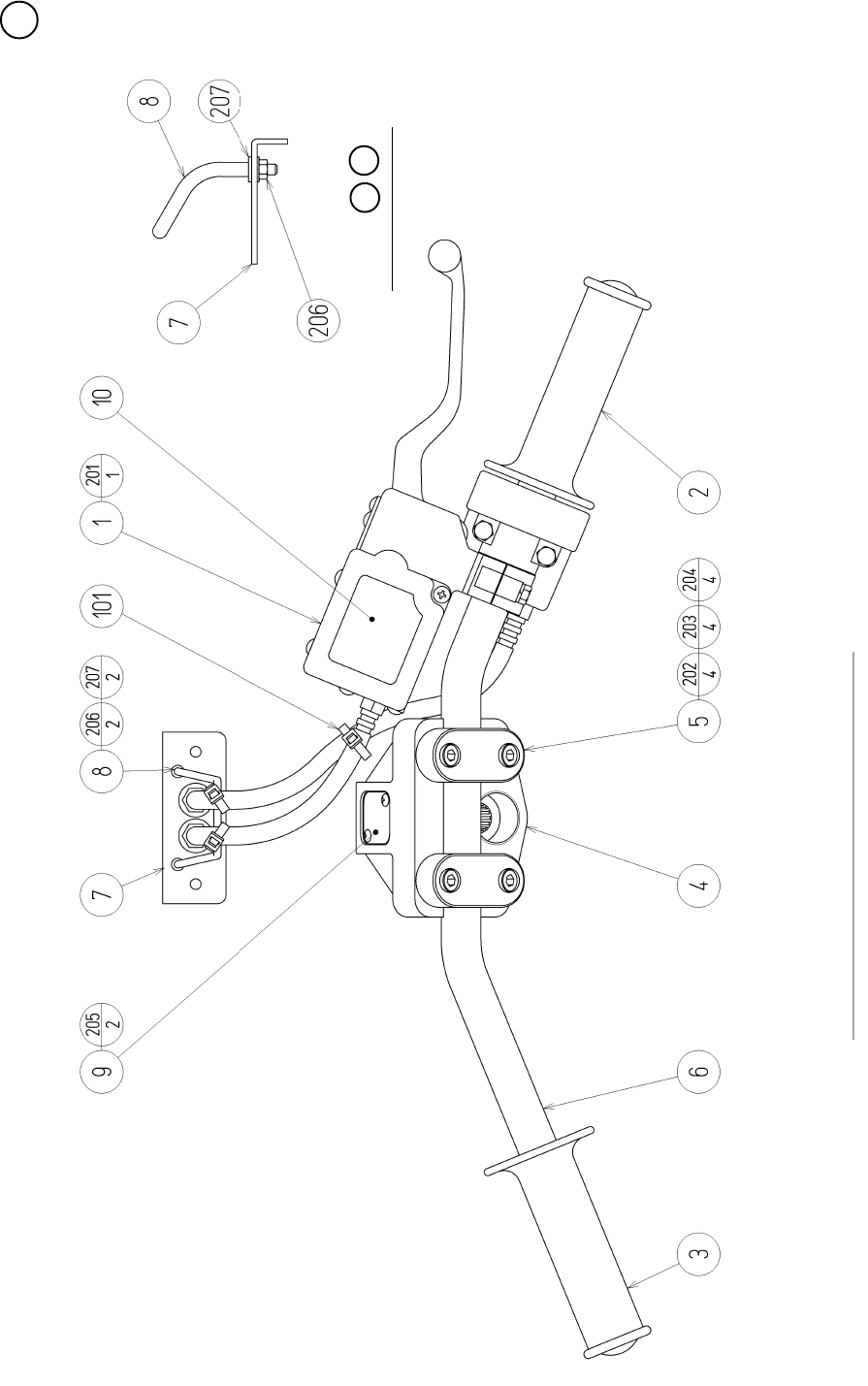
79
2 ASSY HANDLE (WRD-2500) (D-1/2)
M6 SCREW FASTENING TORQUE TO BE : 8.8N•m
Details of 78

80
2 ASSY HANDLE (WRD-2500) (D-2/2)
ITEM NO. PART NO. DESCRIPTION
1 WRD-2550 ASSY BRAKE MEDHA
2 WRD-2600 ASSY THROTTLE
3 HLD-2002 GRIP LEFT
4 MJT-3603X MOUNT BLOCK
5 MJT-3612 HANDLE HOLDER
6 WRD-2501 HANDLE BAR
7 WRD-2502 WIRE MOUNT PLATE
8 WRD-2503 WIRE STAY
9 WRD-2504 HOLE LID
10 WRD-2505 STICKER MASTER CYLINDER
101 280-6623-1S-0 PLASTIC TIE BELT PLT-1S-0
201 000-T00412-0B M SCR TH BLK M4 X 12
202 020-000620-0Z HEX SKT H CAP SCR BLK 0Z M6 X 20
203 060-F00600-0B FLT WSHR BLK M6
204 060-S00600-0B SPR WSHR BLK M6
205 000-T00310-0C M SCR TH CRM M3 X 10
206 050-F00300 FLG NUT M3
207 060-F00300-0B FLT WSHR BLK M3
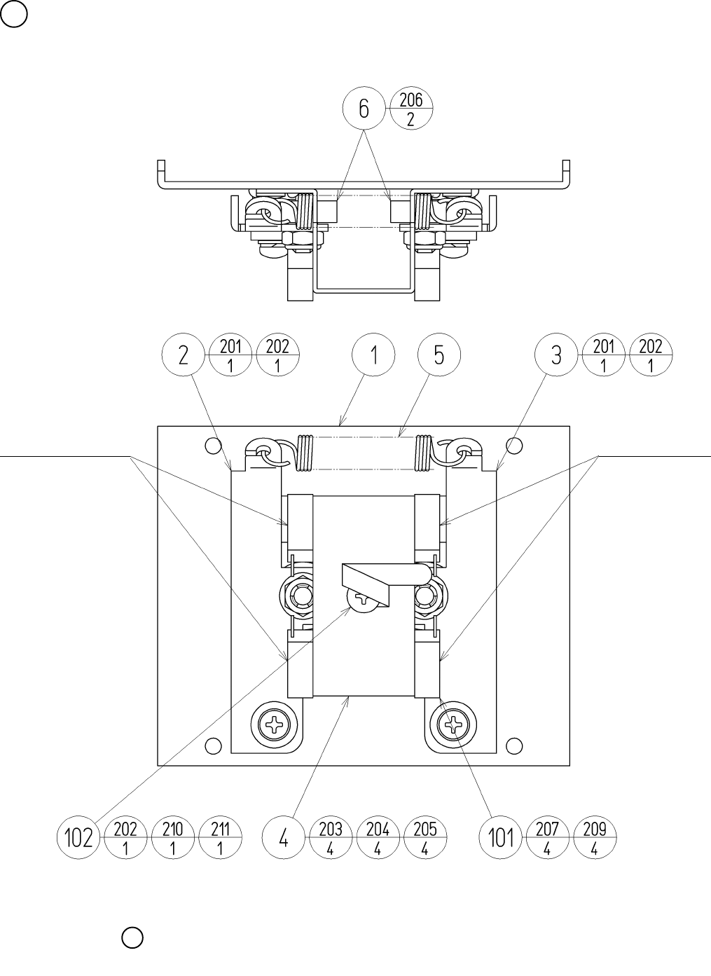
81
3 ASSY CENTERING BASE (WRD-2100) (D-1/2)
The tightening torque to each screw shall be 2.45 N•m.
Light Emitting Side
Light Receiving Side
6

82
3 ASSY CENTERING BASE (WRD-2100) (D-2/2)
ITEM NO. PART NO. DESCRIPTION
1 WRD-2101 FRONT COVER
2 WRD-2102 CENTERING ARM L
3 WRD-2103 CENTERING ARM R
4 WRD-2104 SW BRKT
5 WRD-2105 SPRING HOLD
6 100-5050 ROLLER BEARING 19
7 421-7226-12-91 STICKER L LONG
8 421-7226-21-91 STICKER U LONG
101 370-5232 PHOTO SENSOR OMT-01DS
102 280-0419 HARNESS LUG
201 000-P00410-S M SCR PH W/S M4 X 10
202 060-F00400 FLT WSHR M4
203 050-U00300 U NUT M3
204 060-S00300 SPR WSHR M3
205 060-F00300 FLT WSHR M3
206 050-U00600 U NUT M6
207 000-P00312-W M SCR PH W/FS M3 X 12
209 050-H00300 HEX NUT M3
210 000-P00408 M SCR PH M4 X 8
211 060-S00400 SPR WSHR M4
301 WRD-60003 WH CENTERING MECHA01
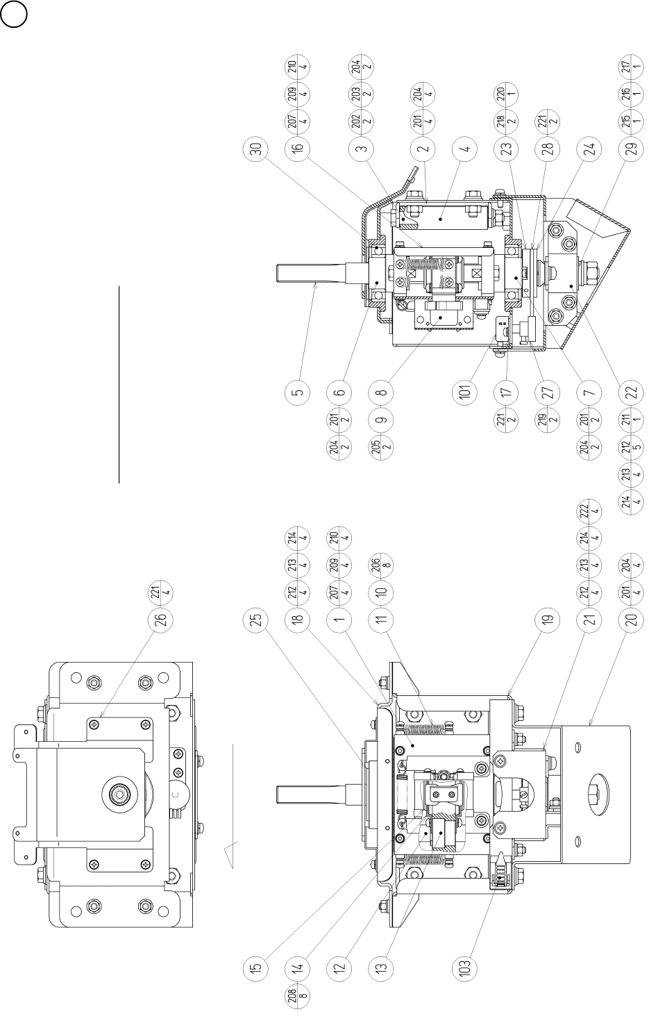
83
4 ASSY HANDLE MECHA (WRD-2000) (D-1/3)
Grease the gear and sliding section.
Toward VOLUME D-Cut

84
4 ASSY HANDLE MECHA (WRD-2000) (D-2/3)
ITEM NO. PART NO. DESCRIPTION
1 WRD-2100 ASSY CENTERING MECHA
2 WRD-2001 STOPPER BRKT
3 WRD-2002 STOPPER SHAFT
4 WRD-2003 STOPPER ROT
5 WRD-2004 MAIN SHAFT
6 WRD-2005 SHAFT HOLDER UPPER
7 WRD-2006 SHAFT HOLDER LOWER
8 WRD-2007 SW SHADE
9 WRD-2009 HOLD CAM
10 WRD-2010 SPRING SUS
11 WRD-2011 SPRING HOOK
12 WRD-2012 GUIDE SHAFT
13 WRD-2013 GUIDE BLOCK
14 WRD-2014 STOPPER HOLDER
15 WRD-2015 STOPPER PP
16 WRD-2016 REAR COVER
17 WRD-2017 VR BRKT
18 WRD-2018 MECHA COVER
19 WRD-2019 MECHA BASE
20 WRD-2020 BASE BRKT
21 WRD-2021 ROSTA BASE
22 WRD-2022 ROSTA HOLDER
23 WRD-2023 GEAR BASE
24 WRD-2024 GEAR NUT PLATE
25 WRD-2025 HIDE PLATE
26 WRD-2026 TOP COVER
27 601-6555 GEAR Z=30 M=0.75
28 601-6450 GEAR 110
29 601-10999 TORSION RUBBER KURASHIKI 18 X 30
30 100-5071 BEARING 30
101 220-5373 VOL CONT B-5K
102 310-5029-F20 SUMITUBE F F 20MM
103 280-5009 CORD CLAMP 21

85
4 ASSY HANDLE MECHA (WRD-2000) (D-3/3)
ITEM NO. PART NO. DESCRIPTION
201 030-000820-S HEX BLT W/S M8 X 20
202 050-H00800 HEX NUT M8
203 060-S00800 SPR WSHR M8
204 060-F00800 FLT WSHR M8
205 000-P00416-W M SCR PH W/FS M4 X 16
206 000-P00420-S M SCR PH W/S M4 X 20
207 029-0427 HEX SKT H CAP SCR M4 X 10
208 000-P00408-W M SCR PH W/FS M4 X 8
209 060-S00400 SPR WSHR M4
210 060-F00400 FLT WSHR M4
211 000-P00612-S M SCR PH W/S M6 X 12
212 060-F00600 FLT WSHR M6
213 060-S00600 SPR WSHR M6
214 050-U00600 U NUT M6
215 050-H01200 HEX NUT M12
216 060-F01200 FLT WSHR M12
217 060-S01200 SPR WSHR M12
218 028-C00412-P SET SCR CH CUP P M4 X 12
219 028-C00406-P SET SCR CH CUP P M4 X 6
220 065-S025S0-Z STP RING BLK 0Z S25
221 000-P00412-W M SCR PH W/FS M4 X 12
222 000-P00512-W M SCR PH W/FS M5 X 12
301 WRD-60004 WH HANDLE MECHA01

86
5 ASSY BRAKE MECHA (WRD-2550) (D-1/2)
SCREW, NUT FASTENING TORQUE TO BE
M4 : 1.8 N•m
M6 : 7.3 N•m
Grease the gear and sliding section.
GREASING

87
5 ASSY BRAKE MECHA (WRD-2550) (D-2/2)
ITEM NO. PART NO. DESCRIPTION
1 HLD-2501 BRAKE MASTER CASE
2 HLD-2502 MASTER CASE HOLDER
3 HLD-2503 MASTER CASE COVER
4 HLD-2504 BRAKE GEAR
5 HLD-2505 IDOL GEAR
6 HLD-2506 PIVOT SHAFT
7 HLD-2507 VR BRKT
8 HLD-2508 LEVER STOPPER
9 HLD-2509 IDOL GEAR SHAFT
10 WRD-2551 MASTER PISTON
11 280-6619 RUBBER FOOT T 3G
12 HLD-2512 BRAKE LEVER
13 HLD-2513 VR COVER
14 HLD-2514 RETURN SPRING
101 220-5484 VOL CONT B-5K OHM
102 601-7944 GEAR 15
103 310-5029-F20 SUMITUBE F F 20MM
104 280-5275-SR10 CORD CLAMP SR10
201 000-T00408-0B M SCR TH BLK M4 X 8
202 050-C00400-3B CAP NUT TYPE3 BLK M4
203 000-P00408-W M SCR PH W/FS M4 X 8
204 030-000620-SB HEX BLT W/S BLK M6 X 20
205 028-A00306-P SET SCR HEX SKT CUP P M3 X 6
206 FAS-500015 CAP NUT BLK M6
207 065-S016H0-Z STP RING BLK OZ H16
208 068-441616 FLT WSHR 4.4-16 X 1.6
209 060-F00600-0B FLT WSHR BLK M6
210 000-P00408 M SCR PH M4 X 8
211 060-S00400 SPR WSHR M4
212 060-F00400 FLT WSHR M4
301 WRD-60006 WH BRAKE MECHA01
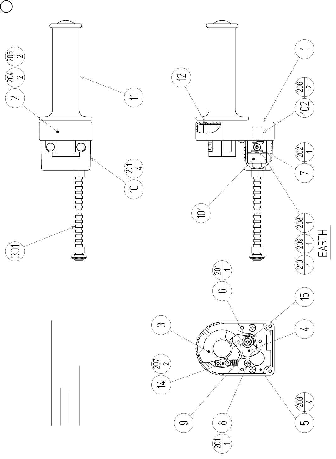
88
6 ASSY THROTTLE (WRD-2600) (D-1/2)
SCREW FASTENING TORQUE TO BE
M3 : 0.75 N•m
M4 : 1.8 N•m
Grease the gear section.

89
6 ASSY THROTTLE (WRD-2600) (D-2/2)
ITEM NO. PART NO. DESCRIPTION
1 HLD-2601 THROTTLE CASE LOWER
2 HLD-2602 THROTTLE CASE UPPER
3 HLD-2603 INNER GRIP
4 HLD-2604 ACCEL GEAR
5 HLD-2605 BASE PLATE
6 HLD-2606 ACCEL GEAR SHAFT
7 HLD-2607 ACCEL VR BRKT
8 HLD-2608 SPRING HOOK
9 HLD-2609 RETURN SPRING
10 HLD-2610 VR COVER
11 HLD-2611 ACCEL GRIP
12 HLD-2612 SLIDE PLATE
14 HLD-2613 SPRING STOPPER
15 HLD-2614 GEAR SPRING
101 220-5484 VOL CONT B-5K OHM
102 601-7944 GEAR 15
103 310-5029-F20 SUMITUBE F F 20MM
201 000-T00408-0B M SCR TH BLK M4 X 8
202 000-P00408-W M SCR PH W/FS M4 X 8
203 000-F00408 M SCR FH M4 X 8
204 030-000625-SB HEX BLT W/S BLK M6 X 25
205 060-F00600-0B FLT WSHR BLK M6
206 028-A00306-P SET SCR HEX SKT CUP P M3 X 6
207 012-P00306 TAP SCR #2 PH 3 X 6
208 000-P00408 M SCR PH M4 X 8
209 060-S00400 SPR WSHR M4
210 060-F00400 FLT WSHR M4
301 WRD-60005 WH THROTTLE01
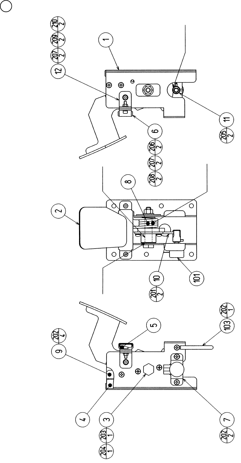
90
7 BRAKE UNIT (CTA-1650) (D-1/2)
GREASING
GREASING
GREASING GREASING
BOTH SIDES

91
ITEM NO. PART NO. DESCRIPTION
1 CTA-1601 PEDAL BASE
2 CTA-1651 BRAKE PEDAL
3 CTA-1603 PEDAL SHAFT
4 CTA-1604 STOPPER BLOCK
5 CTA-1605 RUBBER PLATE
6 CTA-1606 RUBBER CASE
7 CTA-1607 VR BRKT
8 HLD-2805 TORSION SPRING
9 HLD-2808 RUBBER HOLDER
10 601-6450 GEAR 110
11 601-7944 GEAR 15
12 CTA-1608 SUPPORT BRKT
101 220-5373 VOL CONT B-5K
220-5484 VOL CONT B-5K OHM
102 310-5029-F20 SUMITUBE F F 20MM
103 280-0419 HARNESS LUG
201 000-P00412-W M SCR PH W/FS M4 X 12
202 000-P00408-W M SCR PH W/FS M4 X 8
203 050-U00800 U NUT M8
204 060-F00800 FLT WSHR M8
205 028-A00308-P SET SCR HEX SKT CUP P M3 X 8
206 020-000416-0Z HEX SKT H CAP SCR BLK 0Z M4 X 16
207 060-S00400 SPR WSHR M4
208 050-F00400 FLG NUT M4
209 020-000408-0Z HEX SKT CAP SCR BLK 0Z M4 X 8
210 060-F00400 FLT WSHR M4
301 CTA-60050 WIRE HARN BRAKE
7 BRAKE UNIT (CTA-1650) (D-2/2)
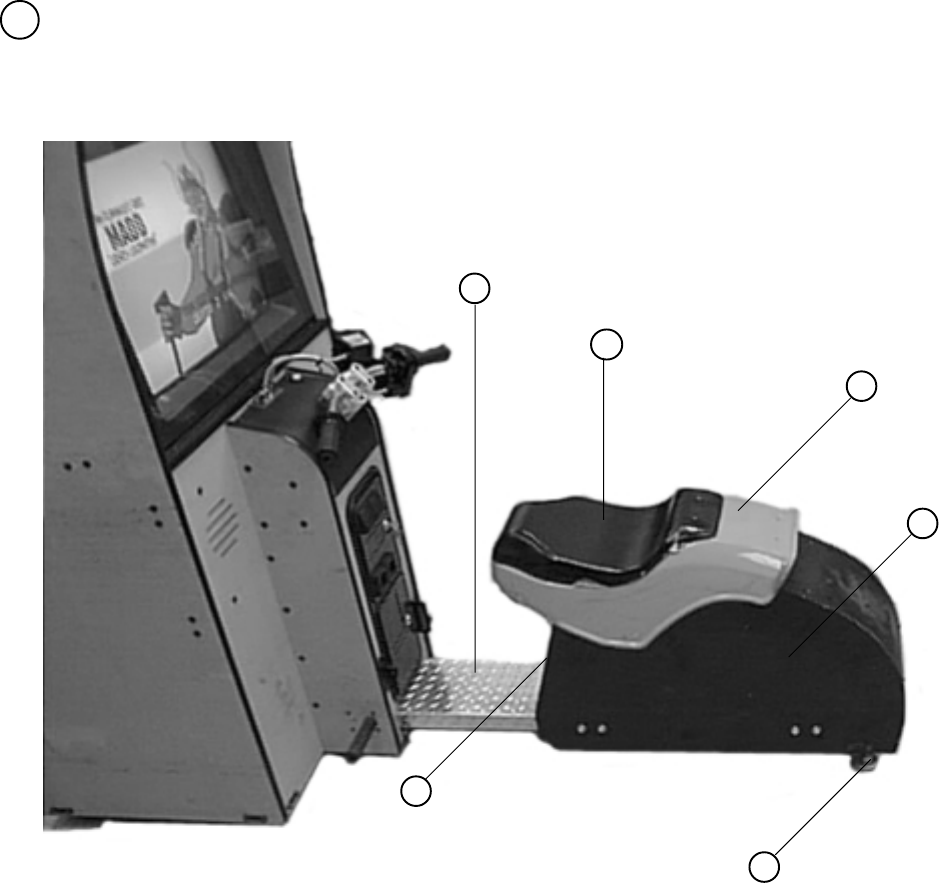
92
8 SEAT CABI
ITEM NO. PART NO. DESCRIPTION
1 999-1171 COVER SEAT VACUUM FORM
2 999-1172 FENDER VACUUM FORM
3 999-1173 S/A; SEAT & FENDER
4 999-0167 LEG LEVELER
5 999-1174 WOOD DOOR SEAT
6 999-1175 PLATE TREAD
1
2
3
4
5
6
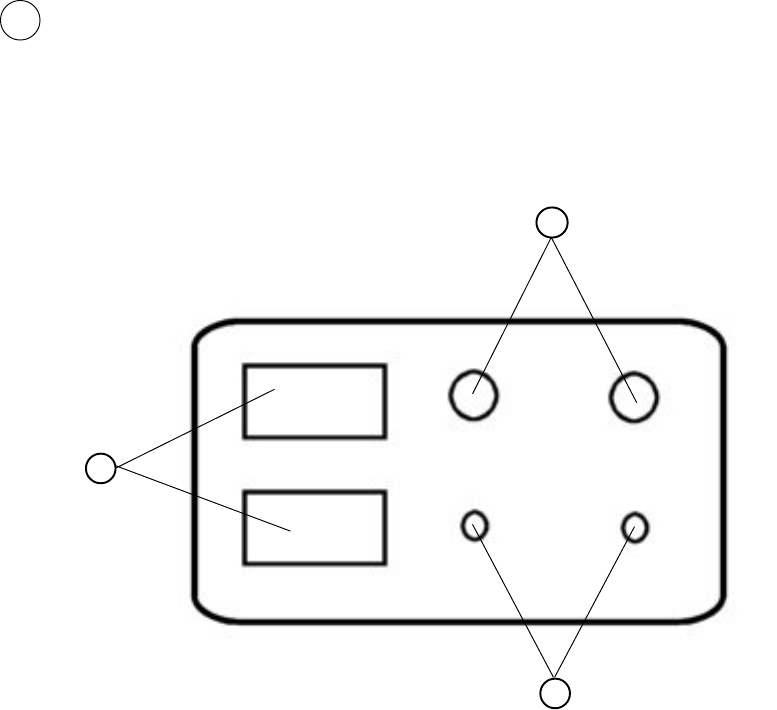
93
ITEM NO. PART NO. DESCRIPTION
1 LOC. PURCHASE 5 K POTENTIOMETER & VOLUME KNOB
2 LOC. PURCHASE MOM. PUSH BUTTON SW
3 LOC. PURCHASE COIN METER 6 VOLTS
9 SW UNIT (CTA-1160)
1
2
3
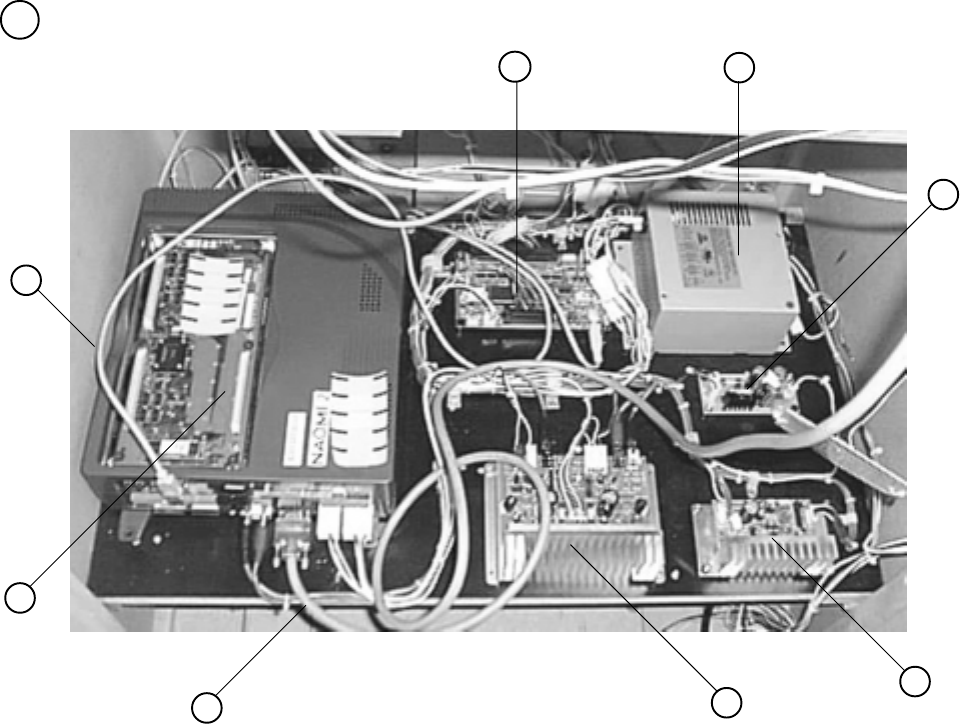
94
10 ASSY MAIN BD
ITEM NO. PART NO. DESCRIPTION
1 837-13551-92 I/O CONTROL BD
2 400-5397-01 POWER SUPPLY FOR JVS
3 838-13759 RECT BD CTA
4 838-11651-01 PC BLOW PASS AMP w/LARGE HEAT SINK
5 838-13616 AUDIO POWER AMP 2 CH
6 600-7009-3000 ASSY RGB CABLE SUB 15P
7 840-0046D-01 ASSY CASE NAO2 WRD US
8 600-7141-200 USB CABLE
Note: Make sure that there is no parts, wiring, etc.
in the slash mark portions.
12
3
4
5
6
7
8
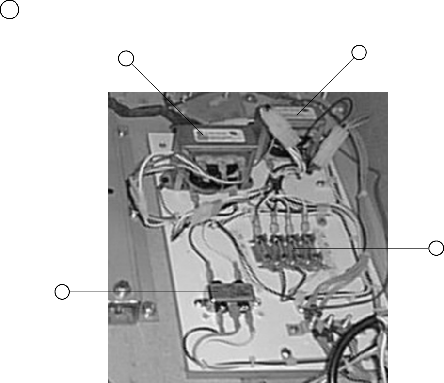
95
11 ASSY XFMR (NOB-4100)
ITEM NO. PART NO. DESCRIPTION
1 998-0147 TRANSFORMER 12V HA MCI-4-06-7012
2 998-0146 TRANSFORMER MCI 4-06-8036
3 LOC. PURCHASE FUSE BLOCK
4 LOC. PURCHASE LINE FILTER 6 AMP
Note: Make sure that there is no parts, wiring, etc.
in the slash mark portions.
12
3
4

96
18. WIRE COLOR CODE TABLE
THE WIRE COLOR CODE is as follow:
A PINK
B SKY BLUE
C BROWN
D PURPLE
E LIGHT GREEN
Wires other than those of any of the above 5 single colors will be displayed by 2
alphanumeric characters.
1 RED
2 BLUE
3 YELLOW
4 GREEN
5 WHITE
7 ORANGE
8 BLACK
9 GRAY
If the right-hand side numeral of the code is 0, then the wire will be of a single color shown
by the left-hand side numeral (see the above).
Note 1: If the right-hand side alphanumeric is not 0, that particular wire has a spiral color
code. The left-hand side character shows the base color and the right-hand side
one, the spiral color.
<Example> 51 .................. WHITE / RED
Note 2: The character following the wire color code indicates the size of the wire.
U: AWG16
K: AWG18
L: AWG20
None: AWG22
RED WHITE
VISIT OUR WEBSITE!