Arcade Winners Cube Classic Manual User
2013-11-28
User Manual: Arcade Winners Cube Classic Manual
Open the PDF directly: View PDF ![]() .
.
Page Count: 22
SERVICE
MANUAL
1SSUEDATE:Jan.
28,2011
-
b
Please read the manual carefully and keep it in mind before
using this machine.
-
b
Put this manual within touch of your reference in anytime.
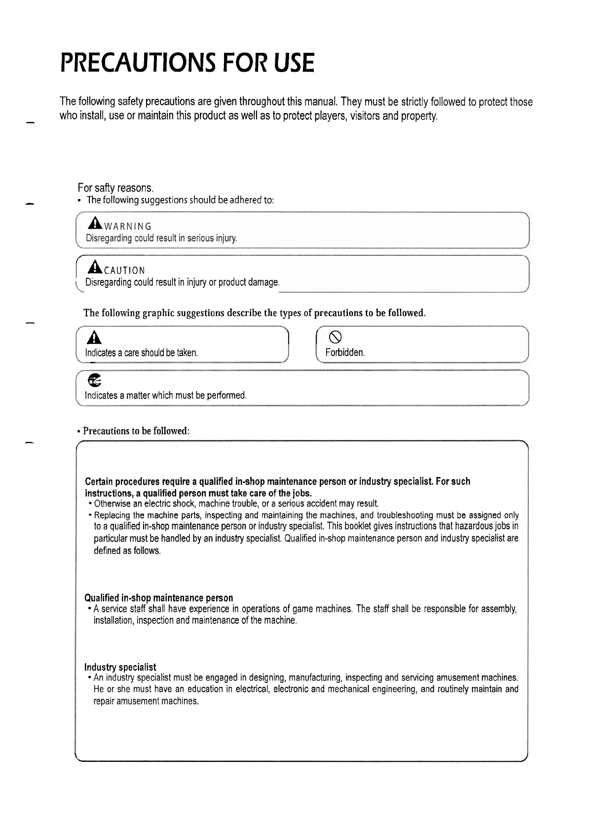
PRECAUTIONS FOR USE
The following safety precautions are given throughout this manual. They must be strictly followed to protect those
-
who install, use or maintain this product as well as to protect players, visitors and property.
For
safty reasons.
-
The following suggestions should
be
adhered to:
r~cAuTloN
Disregarding could result in injury or product damage.
The following graphic suggestions describe the types of precautions to be followed.
-
A
8
Indicates a care should be taken. Forbidden.
-
4E
Indicates a matter which must be performed.
Precautions to be followed:
-
f
\
Certain procedures require a qualified in-shop maintenance person or industry specialist. For such
instructions, a qualified person must take care of the jobs.
Otherwise an electric shock, machine trouble, or a serious accident may result.
-
Replacing the machine parts, inspecting and maintaining the machines, and troubleshooting must be assigned only
to a qualified in-shop maintenance person or industry specialist. This booklet gives instructions that hazardous jobs in
particular must be handled by an industry specialist. Qualified in-shop maintenance person and industry specialist are
defined as follows.
Qualified in-shop maintenance person
A service staff shall have experience in operations of game machines. The staff shall be responsible for assembly,
installation, inspection and maintenance of the machine.
Industry specialist
An industry specialist must be engaged in designing, manufacturing, inspecting and servicing amusement machines.
He or she must have an education in electrical, electronic and mechanical engineering, and routinely maintain and
repair amusement machines.
t
1
PRECAUTIONS FOR USE
[A
WARNING
]
I
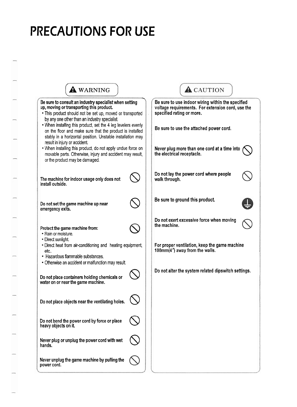
Be sure to consult an industry specialist when setting
up, moving or transporting this product.
This product should not be set up, moved or transported
by any one other than an industry specialist.
When installing this product, set the
4
leg levelers evenly
on the floor and make sure that the product is installed
stably in a horizontal position. Unstable installation may
result in injury or accident.
When installing this product, do not apply undue force on
movable parts. Otherwise, injuly and accident may result,
or the product may be damaged.
The machine for indoor usage only does not
8
install outside.
Do not set the game machine up near
smergency exits.
8
Protect the game machine from:
Rain or moisture.
Direct sunlight.
Direct heat from air-conditioning and heating equipment,
etc..
Hazardous flammable substances.
Otherwise an accident or malfunction may result.
Do not place containers holding chemicals or
water on or near the game machine.
8
DO
not place objects near the ventilating holes.
8
Do not bend the power cord by force or place
O$
heavy objects on
it
Never plug or unplug the power cord with wet
hands.
8
Never unplug the game machine by pulling the
power cord.
Be sure to use indoor wiring within the specified
voltage requirements. For extension cord, use the
specified rating or more.
Be sure to use the attached power cord.
Never plug more than one cord at a time into
the electrical receptacle.
8
Do not lay the power cord where people
walk through.
Be sure to ground this product.
Do not exert excessive force when moving
the machine.
For proper ventilation, keep the game machine
lOOmm(4") away from the walls.
Do not alter the system related dipswitch settings.
PRECAUTIONS FOR USE
(A
WARNING
)
L---
'
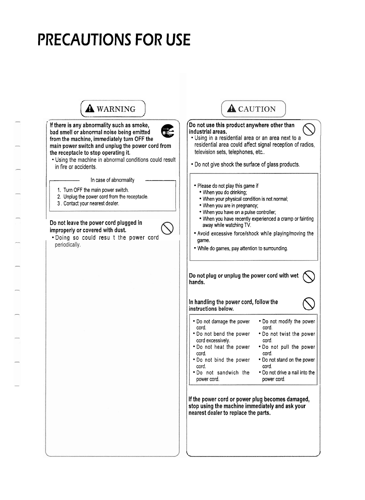
If there is any abnormality such as smoke,
bad smell or abnormal noise being emitted
from the machine, immediately turn
OFF
the
main power switch and unplug the power cord from
the receptacle to stop operating it.
Using the machine in abnormal conditions could result
in fire or accidents.
I-
In case
of
abnormality
71
1.
Turn
OFF
the main power switch,
2.
Unplug the power cord from the receptacle.
3
.
Contact your nearest dealer.
Do not leave the power cord plugged in
improperly or covered with dust.
*Doing so could resu t the power cord
60
not use this product anywhere other than
industrial areas.
Using in a residential area or an area next to a
residential area could affect signal reception of radios,
television sets, telephones, etc..
Do not give shock the surface of glass products.
Please do not play this game if
When you do drinking;
When your physical condition is not normal;
When you are in pregnancy;
When you have on a pulse controller;
When you have recently experienced a cramp or fainting
away while watching TV.
Avoid excessive forcelshock while playinglmoving the
game.
While do games, pay attention to surrounding.
Do not plug or unplug the power cord with wet
hands.
8
In handling the power cord, follow the
instructions below.
8
Do not damage the power Do not modify the power
cord. cord.
Do not bend the power Do not twist the power
cord excessively. cord.
Do not heat the power Do not pull the power
cord. cord.
Do not bind the power Do not stand on the power
cord. cord.
Do not sandwich the Do not drive a nail into the
power cord. power cord.
If the power cord or power plug becomes damaged,
stop using the machine immediately and ask your
nearest dealer to replace the parts.
L
J
PRECAUTIONS FOR USE
(A
WARNING
)
(A
CAUTION
1
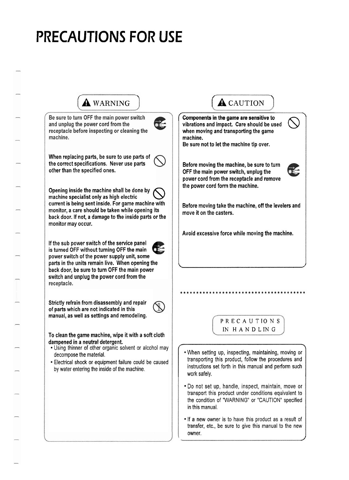
When replacing parts, be sure to use parts of
the correct specifications. Never use parts
other than the specified ones.
Opening inside the machine shall be done by
machine specialist only as high electric
current is being sent inside. For game machine with
monitor, a care should be taken while opening
its
back door. If not, a damage to the inside parts or the
monitor may occur.
If the sub power switch of the service panel
is turned
OFF
without turning OFF the main
power switch of the power supply unit, some
parts in the units remain live. When opening the
back door, be sure to turn
OFF
the main power
switch and unplug the power cord from the
Strictly refrain from disassembly and repair
of parts which are not indicated in this
manual, as well as settings and remodeling.
To clean the game machine, wipe
it
with a soft cloth
dampened in a neutral detergent.
Using thinner of other organic solvent or alcohol may
decompose the material.
Electrical shock or equipment failure could be caused
by water entering the inside of the machine.
/components in the game are sensitive to
\
vibrations and impact. Care should be used
@
when moving and transporting the game
machine.
Be sure not to let the machine tip over.
Before moving the machine, be sure to turn
OFF
the main power switch, unplug the
power cord from the receptacle and remove
the power cord form the machine.
Before moving take the machine, off the levelers and
move
it
on the casters.
Avoid excessive force while moving the machine.
\
1
PRECAUTIONS
IN
HANDLING
f,'
\
When setting up, inspecting, maintaining, moving or
transporting this product, follow the procedures and
instructions set forth in this manual and perform such
work safely.
Do not set up, handle, inspect, maintain, move or
transport this product under conditions equivalent to
the condition of 'WARNING" or "CAUTION" specified
in this manual.
If a new owner is to have this product as a result of
transfer, etc., be sure to give this manual to the new
owner.
J

_I
CONTENTS
I
1-1.
DIMENSION
1-2. SPECIFICATION
-
1-3.
NAME OF PARTS
8
STICKER LOCATION
[
COMPONENTS
I
2.
INSTALLATION
1.
SPECIFICATION AND DIMENSION
1
3.
PRODUCT CHARACTER
4.
SETUP MENU
1
4-1.
SETUP METHOD
4-2. MENU
-1
5.
TROUBLESHOOTING
6.
LIST
7.
PICTURE
8.
PIN LAYOUT OF MAINBOARD
9.
PIN LAYOUT OF SUB-BOARD
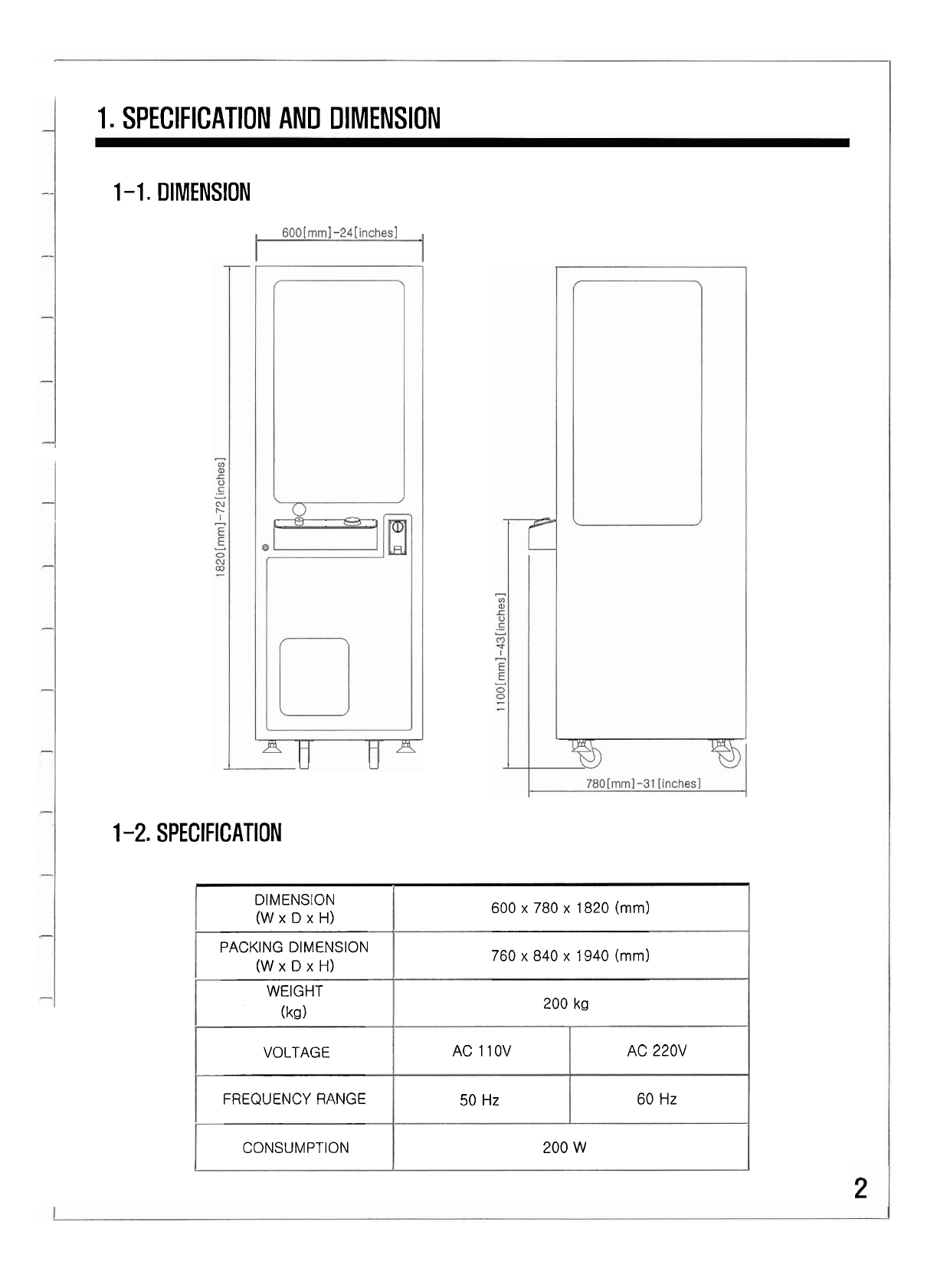
1.
SPECIFICATION AND DIMENSION
1
-1.
DIMENSION
1-2.
SPECIFICATION
DIMENSION
(W
x
D
x
H)
PACKING DIMENSION
(W
x
D
x
H)
WEIGHT
(kg)
VOLTAGE
FREQUENCY RANGE
CONSUMPTION
600
x
780
x
1820 (mm)
760
x
840
x
1940
(mm)
200
kg
AC
110V
50
Hz
AC
220V
60
Hz
200 W
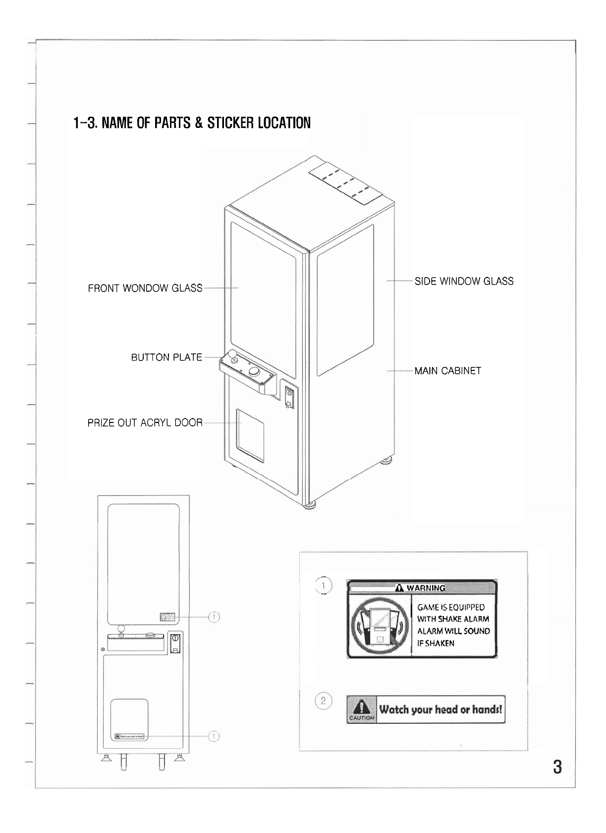
1-3.
NAME OF PARTS
&
STICKER LOCATION
FRONT WONDOW GLASS
BUTTON PLATE
PRIZE
OUT ACRYL DOOR
SIDE WINDOW GLASS
MAIN CABINET
I-.
.-
A
WARNING
;
GhVE
8SEQUlPPED
'
WtTH
SHAKE
ALARM
ALARM
WILL
SOUNO
IF
SHAKEN
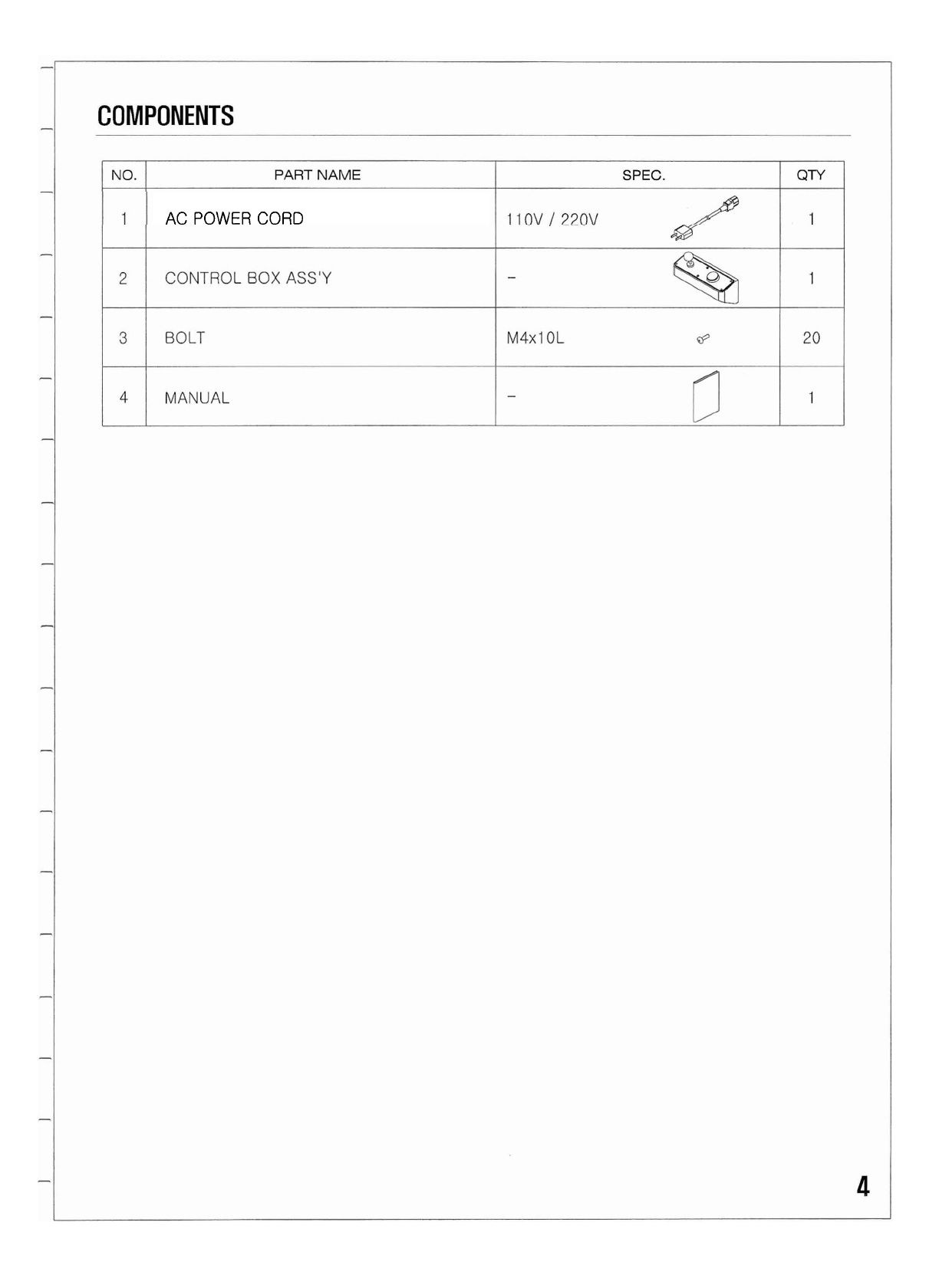
AC POWER CORD
2.
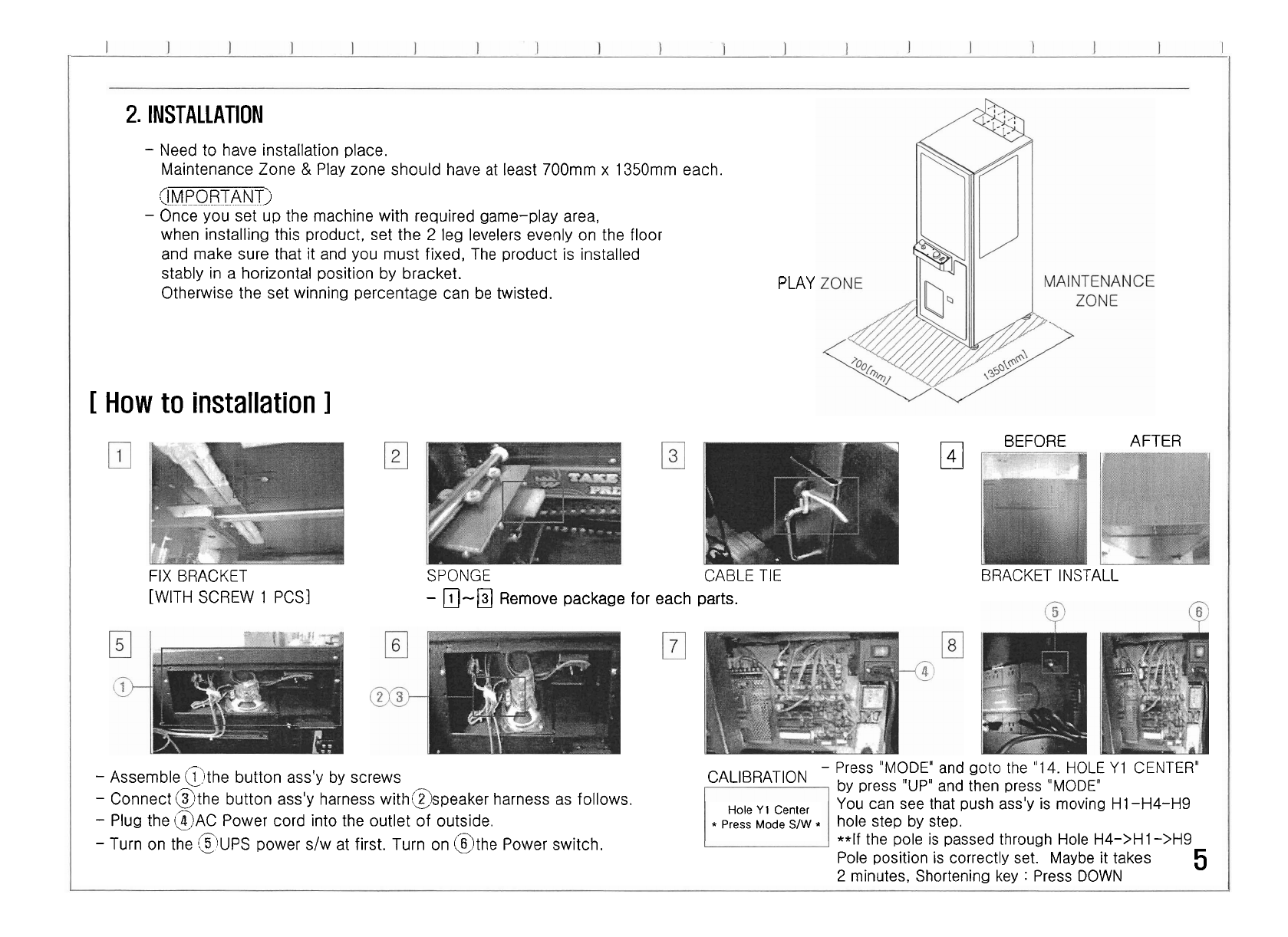
INSTALLATION
-
Need to have installation place.
Maintenance Zone
&
Play zone should have
at
least 700mm x 1350mm each.
<!!!!M-PP0
PP
A
NTj
-
Once you set up the machine with required game-play area,
when installing this product, set the
2
leg levelers evenly on the floor
and make sure that it and you must fixed, The product is installed
stably in a horizontal position by bracket.
Otherwise the set winning percentage can be twisted.
[
How
to installation
I
PLAY
El
BEFORE AFTER
FIX BRACKET
SPONGE
CABLE
TIE
[WITH SCREW 1 PCS]
-
0-0
Remove package for each parts.
BRACKET INSTALL
-
Assemble @]the button ass'y by screws
-
Press
"MODE"
and goto the
"
14.
HOLE
Y
1 CENTER"
CALIBRATloN by press
"UP"
and then press "MODE'
-
connect Elthe button ass'y harness witha
I
2
s p eaker harness as follows. You can see that push ass'y is moving HI -H4-H9
-
Plug the
BAC
Power cord into the outlet of outside. hole step by step.
-
Turn on the
@UPS
power s/w at first. Turn on @the Power switch. **If the pole is passed through Hole
H4->H
1 ->H9
Pole position is correctly set. Maybe it takes
5
2
minutes, Shortening key
:
Press DOWN
Hole
Y
1
Center
Press
Mode
S/W
*
1
3.
PRODUCT CHARACTER
3-1. SPECIALIZED PRODUCT
r-
--
1
1
-
Customized product especially, small location, restaurant, pub and so on.
1
3-2.
INDIVIDUAL PAYOUT RATE
Each cube(l2ea) can be set with individual payout rate.
3-3. DISPLAY
EFFECT
i
1
-
Using various
LED,
Fabulous displaying effect give customer satisfaction.
I
-
1
4.
SET
UP
4-1.
SETUP METHOD
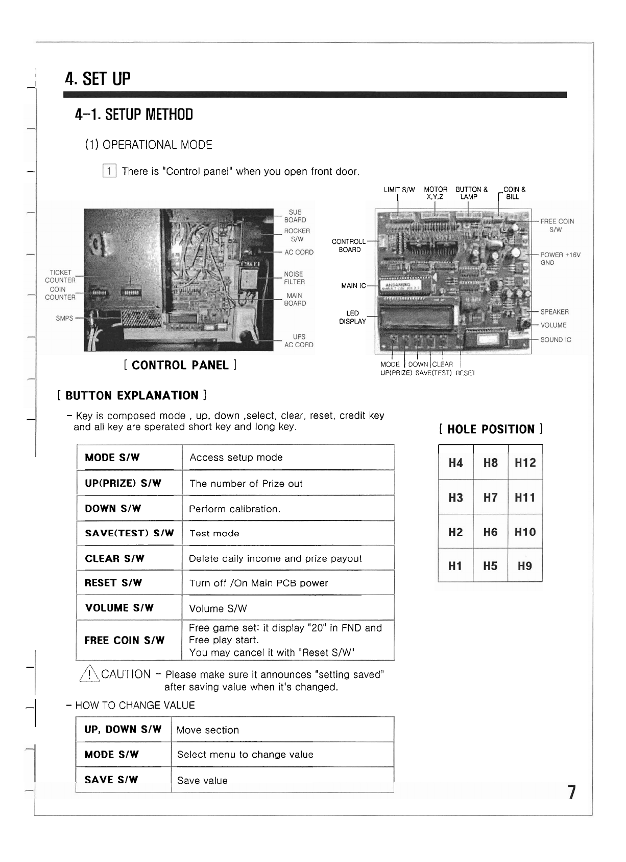
(1)
OPERATIONAL MODE
-I
There is "Control panel" when you open front door.
LIMIT
S/W
MOTOR BUTTON
&
COlN
&
I
x.Y.~
LAMP
r
BILL
[
CONTROL PANEL
I
[
BUTTON EXPLANATION
1
CONTROLL
BOARD
MAIN
IC
LED
OlSPLAY
MobE
1
DdwN
IcLLm
1
UP(PRIZE) SAVE(TEST) RESET
-
-
Key is composed mode
,
up, down ,select, clear, reset, credit key
and all key are sperated short key and long key.
MODE SIW
UP(PRIZE) SIW
DOWN S/W
SAVE(TEST1
S/W
CLEAR SIW
RESET SIW
VOLUME SIW
FREE COlN S/W
-I
-
HOW
TO
CHANGE VALUE
Access setup mode
The number of Prize out
Perform calibration.
Test
mode
Delete daily income and prize payout
Turn off /On Main
PCB
power
Volume S/W
Free game set: it display
"20"
in
FND
and
Free play start.
You may cancel it with "Reset S/WU
-
,7
,.'!I\
CAUTION
-
Please make sure it announces "setting saved"
<
I
after saving value when it's changed.
[
HOLE POSITION
1
-
UP, DOWN SIW
MODE SIW
SAVE S/W
Move section
Select menu to change value
Save value
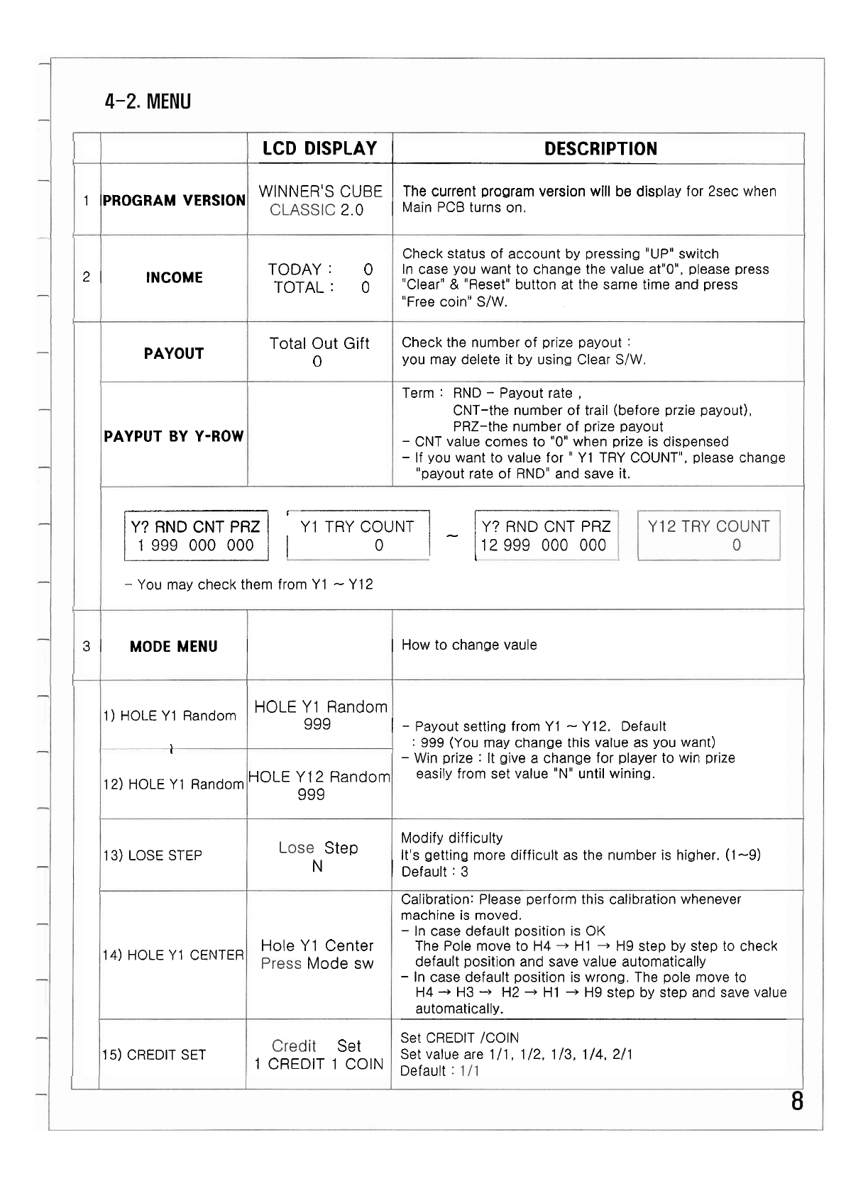
LCD DISPLAY DESCRIPTION
WINNER'S
CUBE
The current program version will be display for 2sec when
1
PROGRAM VERSION
2,0
Main PCB turns on.
Check status of account by pressing "UP" switch
2
INCOME
TODAY
:
0
In case you want to change the value atnO", please press
TOTAL
:
0
"Clear" & "Reset" button at the same time and press
"Free coin" SIW.
Total Out
Gift
Check the number of prize payout
:
PAYOUT
0
you may delete it by using Clear SIW.
Term
:
RND
-
Payout rate
,
CNT-the number of trail (before przie payout),
PRZ-the number of prize payout
PAYPUT BY Y-ROW
-
CNT value comes to "0" when prize is dispensed
-
If you want to value for
"
Y1
TRY COUNT", please change
"payout rate of RND" and save it.
<--
-
--
Y?
RND CNT PRZ
1
r
Y1 TRY COUNT
1
-
IY?
RND CNT PRZ
1
I
999 000 000
1
1
o
i
1
12 999 000 000
&
-
You may check them from
Y1
-
Y 12
3
MODE MENU
How to change vaule
1
)
HOLE
Y
1
Random
HOLE
Y
1
Random
999
-
Payout setting from
Y1
-
Y12.
Default
,
:
999
(You may change this value as you want)
I
-
Win prize
:
It give a change for player to win prize
HOLE
y12
Random easily from set value "Nu until wining.
12)
HOLE Y
1
Random
999
Modify difficulty
13)
LOSE STEP
Step
It's getting more difficult as the number is higher.
(1-9)
N
Default
:
3
Calibration: Please perform this calibration whenever
machine is moved.
-
In case default position
IS
OK
Hole
Y
1
Center The Pole move to H4
+
HI
+
H9 step by step to check
14) HOLE Y
1
CENTER
Mode
sw
default position and save value automatically
-
In case default position is wrong. The pole move to
H4
4
H3
-,
H2
-,
HI
-,
H9
step by step and save value
automatically.
Set CREDIT /COIN
15) CREDIT SET
Set
Set value are 111, 112,
113. 114, 211
1
CREDIT
1
COIN
Default
:
I
LCD DISPLAY
I
DESCRIPTION
17)
DEMO SOUND
1
DEMO SOUND
I
Demo sound On/Off
Default
:
ON
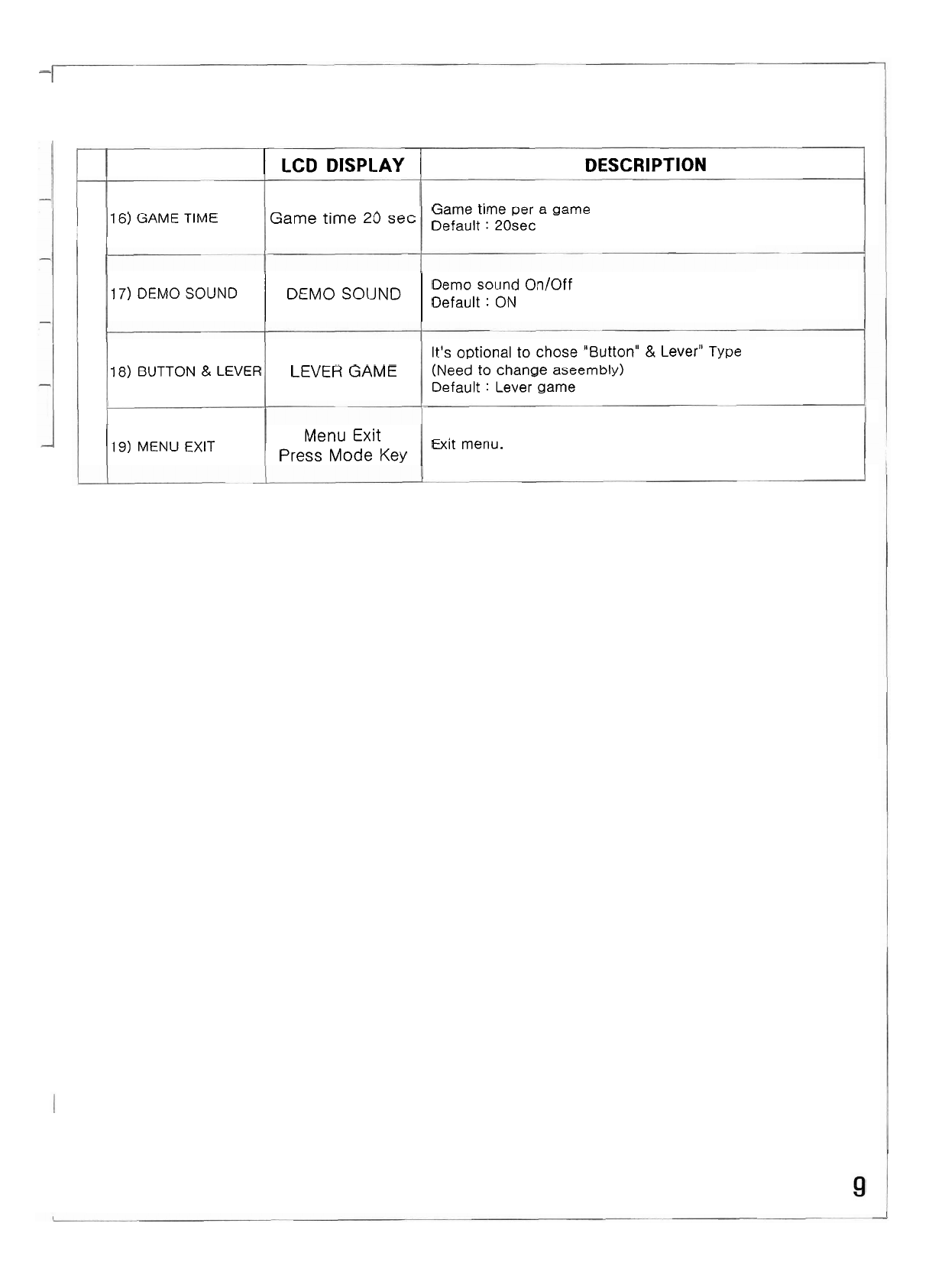
16)
GAME
TIME
Game
time
20
sec
18)
BUTTON
&
LEVER
Game time per a game
Default
:
20sec
11
9)
MENU
EXIT
LEVER
GAME
It's optional
to
chose "Button"
&
Lever"
Type
(Need to change aseembly)
Default
:
Lever game
Menu
Exit
Press
Mode
Key
Exit menu.
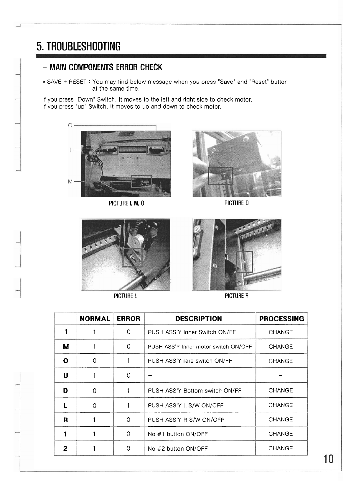
5.
TROUBLESHOOTING
-
MAIN
COMPONENTS ERROR CHECK
*
SAVE
+
RESET
:
You may find below message when you press "Save" and "Reset" button
at the same time.
If you press "Down" Switch, It moves to the left and right side to check motor.
If you press "up" Switch,
It
moves to
up
and down to check motor.
PICTURE
I,
M,
0
PICTURE
D
PICTURE
L
PICTURE
R
DESCRIPTION
PUSH ASS'Y Inner Switch ONIFF
PUSH ASS'Y Inner motor switch ONIOFF
PUSH ASS'Y rare switch ONIFF
-
PUSH
ASS'Y Bottom switch ONIFF
PUSH ASS'Y
L
SIW ONIOFF
PUSH ASS'Y
R
S/W ONIOFF
No
#1
button ONIOFF
No
#2
button ONIOFF
ERROR
0
0
1
0
1
1
0
0
0
I
M
0
U
D
L
R
1
2
PROCESSING
CHANGE
CHANGE
CHANGE
-
CHANGE
CHANGE
CHANGE
CHANGE
CHANGE
NORMAL
1
1
0
1
0
0
1
1
1
L
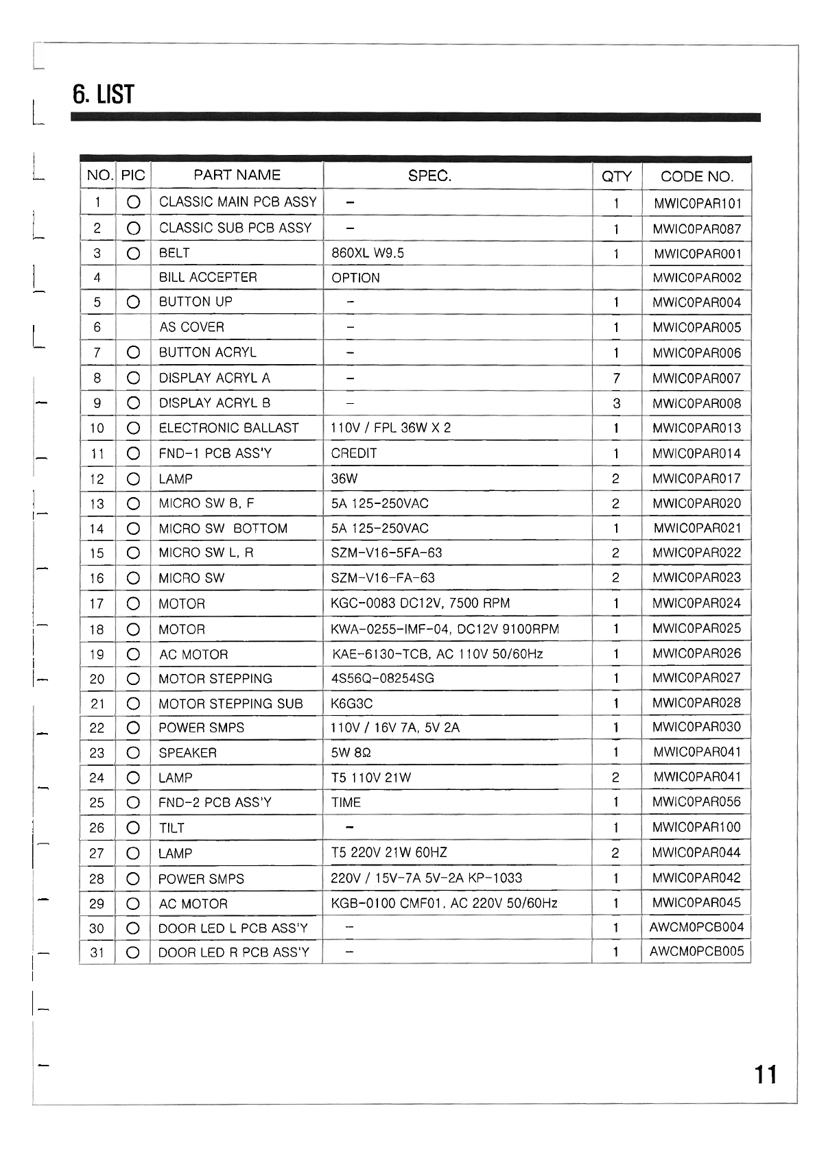
6.
LIST
L
I
L
I
-
I
L
-
-
I
I
-
-
I
-
1
i
1
-
-
-
1-
-
I
-
I
~
-
-
11
NO.
1
2
3
4
5
6
7
8
9
10
11
12
13
14
15
16
17
18
19
20
21
22
23
24
25
26
27
28
29
30
31
PIC
0
0
0
0
0
0
0
0
0
0
0
0
0
0
0
0
0
0
0
0
0
0
0
0
0
0
0
0
0
CODENO.
MWICOPARI 01
MWICOPAR087
MWICOPAR001
MWICOPAR002
MWICOPAR004
MWICOPAR005
MWICOPAR006
MWICOPAR007
MWICOPAR008
MWlCOPARO13
MWICOPAR014
MWICOPAR017
MWICOPAR020
MWICOPAR021
MWICOPAR022
MWICOPARO23
MWICOPAR024
MWICOPAR025
MWICOPAR026
MWICOPAR027
MWICOPAR028
MWICOPAR030
MWICOPAR041
MWICOPAR041
MWICOPARO56
MWICOPARI 00
MWICOPAR044
MWICOPAR042
MWICOPAR045
AWCMOPCB004
AWCMOPCB005
QTY
1
1
1
1
1
1
7
3
1
1
2
2
1
2
2
1
1
1
1
1
1
1
2
1
1
2
1
1
1
1
PART
NAME
CLASSIC MAIN PCB ASSY
CLASSIC SUB PCB ASSY
BELT
BILL ACCEPTER
BUTTON UP
AS COVER
BUTTON ACRYL
DISPLAY ACRYL A
DISPLAY ACRYL B
ELECTRONIC BALLAST
FND-1 PCB ASS'Y
LAMP
MICRO SW 6, F
MICRO SW BOTTOM
MICRO SW L, R
MICRO SW
MOTOR
MOTOR
AC MOTOR
MOTOR STEPPING
MOTOR STEPPING SUB
POWER SMPS
SPEAKER
LAMP
FND-2 PCB ASS'Y
TILT
LAMP
POWER SMPS
AC MOTOR
DOOR LED L PCB ASS'Y
DOOR LED R PCB ASS'Y
SPEC.
-
-
860XL W9.5
OPTION
-
-
-
-
-
1
1
OV
/
FPL 36W
X
2
CREDIT
36W
5A 125-250VAC
5A 125-250VAC
SZM-V16-5FA-63
SZM-V16-FA-63
KGC-0083 DC12V. 7500 RPM
KWA-0255-IMF-04, DC12V 91 00RPM
KAE-6130-TCB, AC 1 10V 50160Hz
4S56Q-08254SG
K6G3C
110V
/
16V 7A, 5V 2A
5W
8Q
T5 110V 21W
TIME
-
T5 220V 21 W 60HZ
220V
/
15V-7A 5V-2A KP-1033
KGB-01 00 CMFO1, AC 220V 50/60Hz
-
-
1
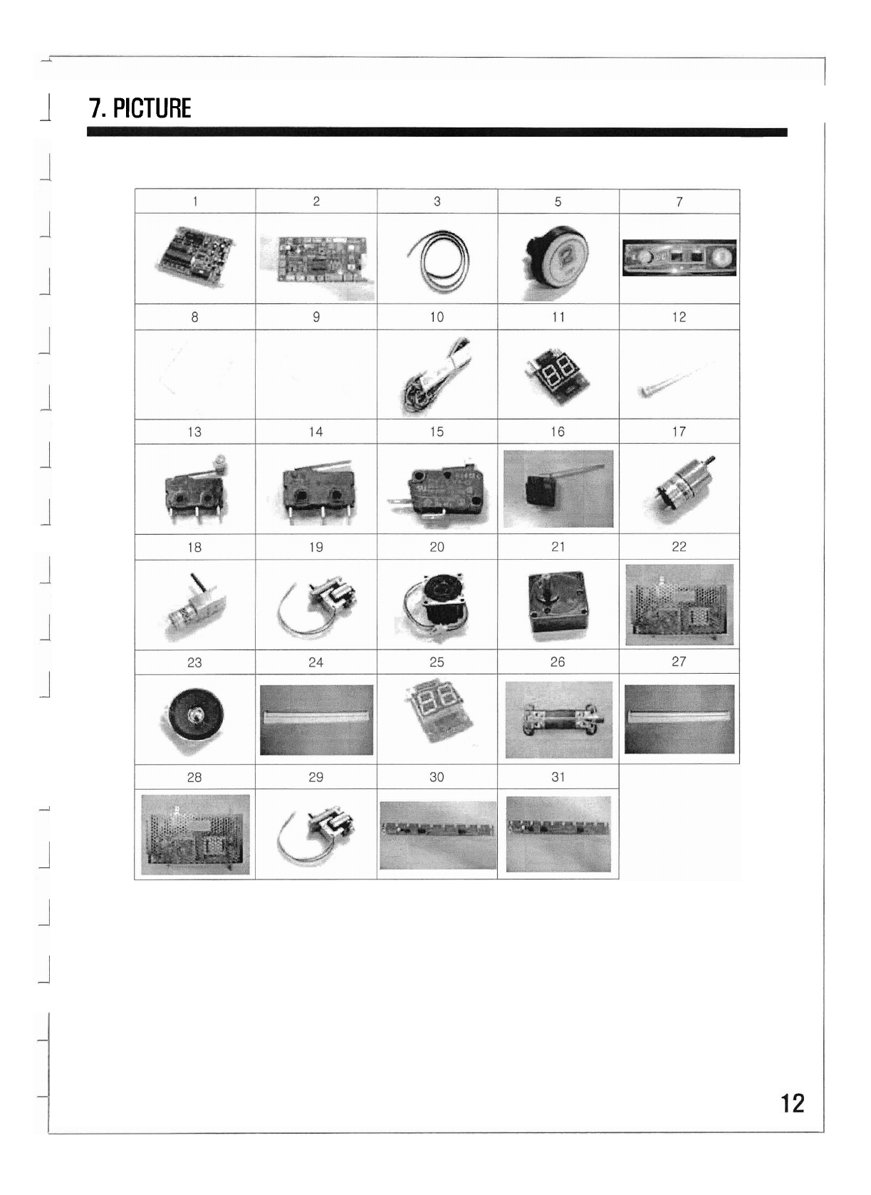
7.
PICTURE
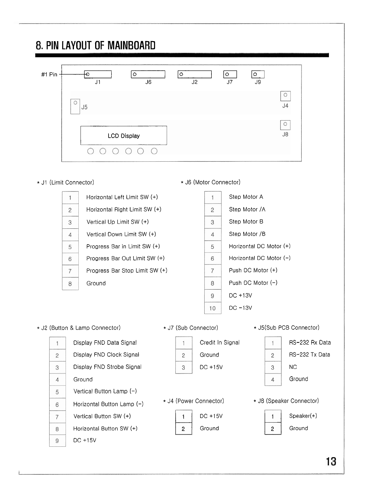
8.
PIN LAYOUT OF MAINBOARD
#I
Pin
loIElD
1-
Jf3
J 2
J
7
J9
LCD Display
c
*
J1 (Limit Connector)
Horizontal Left Limit SW
(+)
Horizontal Right Limit SW
(+)
Vertical Up Limit SW
(+I
Vertical Down Limit SW
(+)
Progress Bar in Limit SW
(+I
Progress Bar Out Limit SW
(+)
Progress Bar Stop Limit SW
(+)
Ground
*
J6 (Motor Connector)
Step Motor A
Step Motor /A
Step Motor B
Step Motor /B
Horizontal DC Motor
(+I
Horizontal DC Motor
(-1
Push DC Motor
(+)
Push DC Motor
(-)
DC +13V
DC -13V
*
J2 (Button
&
Lamp Connector)
*
J7
(Sub Connector)
*
J5(Sub PCB Connector)
Display FND Data Signal
Display FND Clock Signal
Display FND Strobe Signal
Ground
Credit In Signal
Ground
DC +15V
RS-232 Rx Data
RS-232 Tx Data
N
C
Ground
Vertical Button Lamp
(-)
Horizontal Button Lamp
(-)
*
J4
(Power Connector)
*
J8 (Speaker Connector)
Vertical Button SW
(+)
DC +15V Speaker(+)
Horizontal Button SW
(+)
Ground Ground
DC +15V
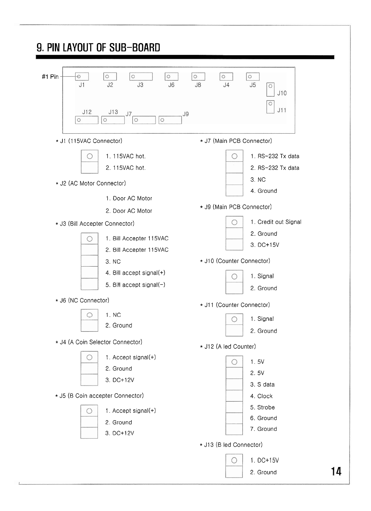
9.
PIN
LAYOUT OF SUB-BOARD
#I
Pin
*
J1
(1
15VAC Connector)
1.
115VAC hot.
2. 115VAC hot.
*
J2 (AC Motor Connector)
1. Door AC Motor
2. Door AC Motor
*
J3 (Bill Accepter Connector)
1. Bill Accepter 1 15VAC
2. Bill Accepter
I
1
5VAC
3. NC
4. Bill accept signal(+)
5. Bill accept signal(-)
*
J6
(NC Connector)
1.
NC
2. Ground
*
J4 (A Coin Selector Connector)
1.
Accept signal(+)
2.
Ground
3. DC+12V
*
J5
(6
Coin accepter Connector)
1.
Accept signal(+)
2.
Ground
3. DC+12V
*
J7
(Main PCB Connector)
1. RS-232
Tx
data
2.
RS-232
Tx
data
3.
NC
4.
Ground
*
J9 (Main PCB Connector)
1.
Credit out Signal
2. Ground
3. DC+15V
*
J10 (Counter Connector)
1. Signal
2. Ground
*
J11 (Counter Connector)
1.
Si~nal
2. Ground
*
J12 (A led Counter)
1. 5v
2. 5v
3. S data
4.
Clock
5. Strobe
6.
Ground
7.
Ground
*
J13 (B led Connector)
1.
DC+15V
2. Ground

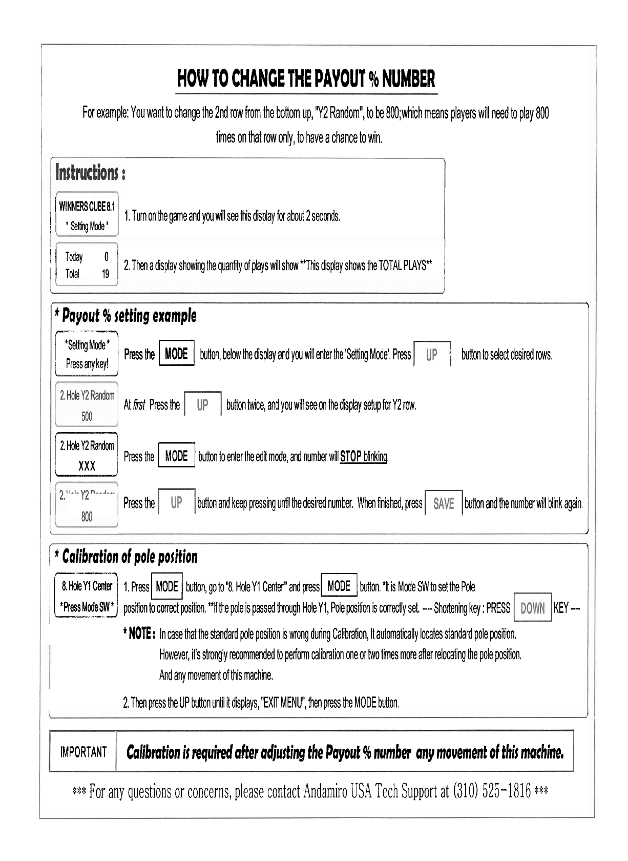
HOW TO CHANCE THE PAYOUT
%
NUMBER
For example: You want to change the
2nd
row from the bolom up,
'Y2
Random", to be 8M);which means players will need to play 800
times on that row only, to have a chance to win.
1
WINNERSCUBE
81
1.
Turn on the game and you will see this display for about
2
seconds.
/
'setingMi
I
Today
:
1
2.
Then a display showing the quantii of plays will show *This display shows the TOTAL PLAYS*
1
I
Total
1
*
Payout
%
jetting example
PetiniMoq
c
j
Pressany
key!
J
Press the
MODE
button, below the display and you will enter the 'Setting Mode', Press button to select desired rows,
At
frst
Press the button twice, and
yar
will see on the display setup for
Y2
row.
2.
Hole
Y2
Random
IT]
Press the
pi
button to enter the edit mode, and number will
STOP
blinkin!,
Press the button and keep pressing until the desired number. When finished, press button and the number will blink again.
I
/
*
Calibration of pole position
8.
Hole
Y1
Center
I,
Press
MODE
buloton, go to
"8.
Hole
Y1
Center"' and presswI button,
*It
is Mode SW to set the Pole
'Press
---
Made
.--
SWJ
posii to correct position, "Hhe pole is passed through HoleY1, Pole pition is correctly set,
--
Shortening key
:
PRESS
c
-------I
*
NOTE
:
In case that the standard pole position is wrong during Calibmtion, It automatically locates standard pole position.
However, it's strongly recommended to perform calibration one or two times more after relocating the pole position,
And any movement of this machine.
2.
Then press the UP button until it displays,
"EXIT
MENU", then press the MODE button.
1
KEY
.--
War
any questions or concerns, please contact Andarniro
USA
Tech Support at
(310)
525-1816
***
IMPORTANT
Calibration
ij
required after adjusting the Payout
%
number any movement of thij machinee
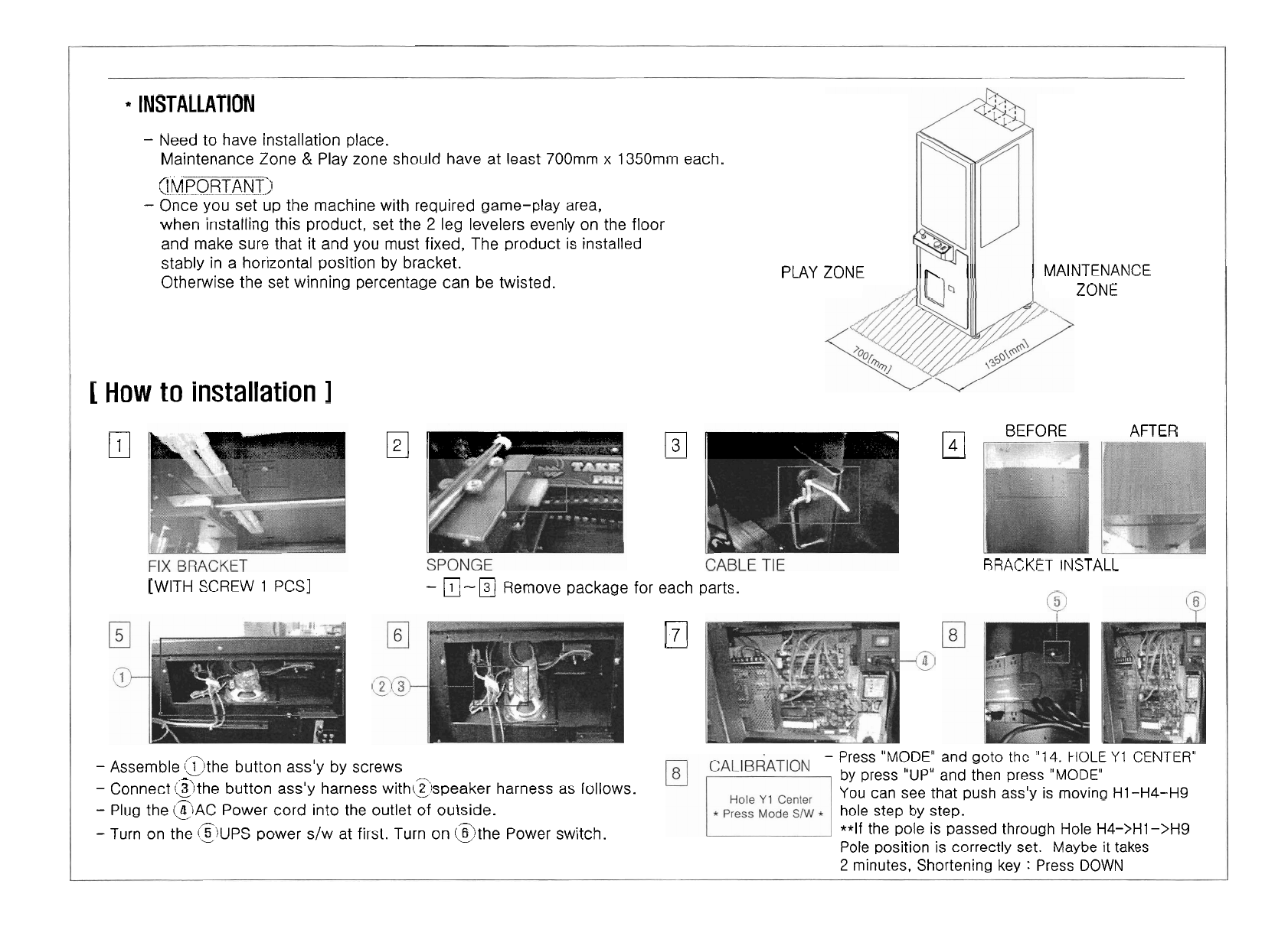
INSTALLATION
-
Need to have installation place.
Maintenance Zone
&
Play zone should have at least 700mm
x
1350mm each.
/-
i!..MPOH!iNT)
-
Once you set up the machine with required game-play area,
when installing this product, set the
2
leg levelers evenly on the floor
and make sure that it and you must fixed, The product is installed
stably in a horizontal position by bracket.
Otherwise the set winning percentage can be twisted. PLAY ZONE MAINTENANCE
ZONE
[
How
to installation
I
El
El
El
BEFORE AFTER
BRACKET INSTALL
[WITH
SCREW
1
PCSI
-
m-m
Remove package for each parts.
El
-
Assemble @the button ass'y by screws
-
Press
"MODE"
and goto
the
"14.
HOLE
Y1
CENTER"
by
press "UP" and then press
"MODE'
-
Connect (21the button ass'y harness withtzspeaker harness as follows.
YOU
can see that push ass'y is moving HI-H4-H9
-
Plug the
(ZIAC
Power cord into the outlet of outside. hole step by step.
-
Turn on the
i3k.J~~
power s/w at first. Turn on @the Power switch. **If the pole is passed through Hole H4->HI->H9
Pole position is correctly set. Maybe
it
takes
2
minutes, Shortening key
:
Press
DOWN
