Arcadyan Technology AR4505NWB DIGITAL TRANSMISSION SYSTEM User Manual 00
Arcadyan Technology Corporation DIGITAL TRANSMISSION SYSTEM 00
USERS MANUAL

ADSL Router with 4-Port LAN
Switch and 802.11g WLAN
3100-4g V2
3100-4g V2
April 2008
R.01 f/w 0.72

iii
C
OMPLIANCES
EC Conformance Declaration
Marking by the above symbol indicates compliance with the Essential Requirements of the
R&TTE Directive of the European Union (1999/5/EC). This equipment meets the
following conformance standards:
EN 300 328
EN 301 489-1
EN 301 489-17
EN 60950-1
Industry Canada Statement
This device complies with RSS-210 of the Industry Canada Rules. Operation is subject to the
following two conditions:
(1). this device may not cause interference and
(2). this device must accept any interference, including interference that may cause undesired
operation of the device
This Class A digital apparatus complies with Canadian ICES-003.
Cet appareil numerique de la class A est conforme a la norme NMB-003 du Canada.
IMPORTANT NOTE:
IC Radiation Exposure Statement:
This equipment complies with Canada radiation exposure limits set forth for uncontrolled
environments. This equipment should be installed and operated with minimum distance
20cm between the radiator & your body.
This transmitter must not be co-located or operating in conjunction with any other antenna
or transmitter.
2.4GHz operation of this product in Canada is firmware-limited to channels 1 through 11.

C
OMPLIANCES
iv
Federal Communication Commission Interference
Statement
This equipment has been tested and found to comply with the limits for a Class B digital
device, pursuant to Part 15 of the FCC Rules. These limits are designed to provide reasonable
protection against harmful interference in a residential installation. This equipment generates,
uses and can radiate radio frequency energy and, if not installed and used in accordance with
the instructions, may cause harmful interference to radio communications. However, there is
no guarantee that interference will not occur in a particular installation. If this equipment
does cause harmful interference to radio or television reception, which can be determined by
turning the equipment off and on, the user is encouraged to try to correct the interference by
one of the following measures:
• Reorient or relocate the receiving antenna.
• Increase the separation between the equipment and receiver.
• Connect the equipment into an outlet on a circuit different from that to which the receiver
is connected.
• Consult the dealer or an experienced radio/TV technician for help.
This device complies with Part 15 of the FCC Rules. Operation is subject to the following
two conditions: (1) This device may not cause harmful interference, and (2) this device must
accept any interference received, including interference that may cause undesired operation.
FCC Caution: Any changes or modifications not expressly approved by the party
responsible for compliance could void the user's authority to operate this equipment.
IMPORTANT NOTE:
FCC Radiation Exposure Statement:
This equipment complies with FCC radiation exposure limits set forth for an uncontrolled
environment. This equipment should be installed and operated with minimum distance 20cm
between the radiator and your body.
This transmitter must not be co-located or operating in conjunction with any other antenna
or transmitter.
2.4GHz operation of this product in the U.S.A. is firmware-limited to channels 1 through 11.

C
OMPLIANCES
v
FCC Part 68 statement
This equipment complies with Part 68 of the FCC rules and the requirements adopted by the
ACTA. On the bottom of this equipment is a label that contains, among other information, a
product identifier in the format US: ACYDL02BAR4505NWB.If requested, this number
must be provided to the telephone company.
The REN is used to determine the number of devices that may be connected to a telephone
line. Excessive RENs on a telephone line may result in the devices not ringing in response to
an incoming call. In most but not all areas, the sum of RENs should not exceed five (5.0). To
be certain of the number of devices that may be connected to a line, as determined by the
total RENs, contact the local telephone company. For products approved after July 23, 2001,
the REN for this product is part of the product identifier that has the format
US: ACYDL02BAR4505NWB. The digits represented by 02 are the REN without a decimal
point (e.g., 03 is a REN of 0.3). For earlier products, the REN is separately shown on the
label.
A plug and jack used to connect this equipment to the premises wiring and telephone
network must comply with the applicable FCC Part 68 rules and requirements adopted by the
ACTA. A compliant telephone cord and modular plug is provided with this product. It is
designed to be connected to a compatible modular jack that is also compliant. See installation
instructions for details.
If your equipment causes harm to the telephone network, the telephone company may
discontinue your service temporarily. If possible, they will notify you in advance. But if
advance notice is not practical, you will be notified as soon as possible. You will be informed
of your right to file a complaint with the FCC. Your telephone company may make changes
in it is facilities, equipment, operations or procedures that could affect the proper functioning
of your equipment. If they do, you will be notified in advance to give you an opportunity to
maintain uninterrupted telephone service.
If you experience trouble with this telephone equipment, Please contact the following address
and phone number for information on obtaining service or repairs.
The telephone company may ask that you disconnect this equipment from the network until
the problem has been corrected or until you are sure that the equipment is not
malfunctioning.
This equipment may not be used on coin service provided by the telephone company.
Connection to party lines is subject to state tariffs.
If your home has specially wired alarm equipment connected to the telephone line, ensure the
installation of this [equipment ID] does not disable your alarm equipment.
If you have questions about what will disable alarm equipment, consult your telephone
company or a qualified installer.

C
OMPLIANCES
vi
Contact information in the USA
COMPANY: Alpha Telecom Inc. USA
ADDRESS: 1362 Borregas Avenue, Sunnyvale, CA 94089
TEL NO: 1-408-541-6186
Contact person: Judy Lee

vii
T
ABLE OF
C
ONTENTS
1 Introduction . . . . . . . . . . . . . . . . . . . . . . . . . . . . 1-1
About the ADSL router . . . . . . . . . . . . . . . . . . . . . . . . . . . . . . . . . . . . . . 1-1
Features and Benefits . . . . . . . . . . . . . . . . . . . . . . . . . . . . . . . . . . . . . . . . 1-1
Applications . . . . . . . . . . . . . . . . . . . . . . . . . . . . . . . . . . . . . . . . . . . . . . . 1-2
2 Installation . . . . . . . . . . . . . . . . . . . . . . . . . . . . . . 2-1
Package Contents . . . . . . . . . . . . . . . . . . . . . . . . . . . . . . . . . . . . . . . . . . . 2-1
System Requirements . . . . . . . . . . . . . . . . . . . . . . . . . . . . . . . . . . . . . . . . 2-2
Hardware Description . . . . . . . . . . . . . . . . . . . . . . . . . . . . . . . . . . . . . . . 2-2
LED Indicators . . . . . . . . . . . . . . . . . . . . . . . . . . . . . . . . . . . . . . . 2-3
Rear Ports . . . . . . . . . . . . . . . . . . . . . . . . . . . . . . . . . . . . . . . . . . . 2-4
ISP Settings . . . . . . . . . . . . . . . . . . . . . . . . . . . . . . . . . . . . . . . . . . . . . . . . 2-5
Connect the System . . . . . . . . . . . . . . . . . . . . . . . . . . . . . . . . . . . . . . . . . 2-5
Connecting the ADSL Line . . . . . . . . . . . . . . . . . . . . . . . . . . . . . 2-6
Connecting the network . . . . . . . . . . . . . . . . . . . . . . . . . . . . . . . . 2-6
Connecting the Power Adapter . . . . . . . . . . . . . . . . . . . . . . . . . . 2-6
Wall Mounting . . . . . . . . . . . . . . . . . . . . . . . . . . . . . . . . . . . . . . . 2-7
3 Configuring Client PC . . . . . . . . . . . . . . . . . . . . . 3-1
TCP/IP Configuration . . . . . . . . . . . . . . . . . . . . . . . . . . . . . . . . . . . . . . . 3-2
Windows 2000 . . . . . . . . . . . . . . . . . . . . . . . . . . . . . . . . . . . . . . . . . . . . . 3-3
Disable HTTP Proxy . . . . . . . . . . . . . . . . . . . . . . . . . . . . . . . . . . 3-4
Obtain IP Settings from Your ADSL router . . . . . . . . . . . . . . . . 3-4
Windows XP . . . . . . . . . . . . . . . . . . . . . . . . . . . . . . . . . . . . . . . . . . . . . . . 3-6
Disable HTTP Proxy . . . . . . . . . . . . . . . . . . . . . . . . . . . . . . . . . . 3-6
Obtain IP Settings from Your ADSL router . . . . . . . . . . . . . . . . 3-6
Configuring Your Macintosh Computer . . . . . . . . . . . . . . . . . . . . . . . . . 3-8
Disable HTTP Proxy . . . . . . . . . . . . . . . . . . . . . . . . . . . . . . . . . . 3-9

T
ABLE OF
C
ONTENTS
viii
4 Configuring the ADSL Router . . . . . . . . . . . . . . .4-1
Navigating the Management Interface . . . . . . . . . . . . . . . . . . . . . . . . . . 4-2
Making Configuration Changes . . . . . . . . . . . . . . . . . . . . . . . . . . 4-3
Set-up Wizard . . . . . . . . . . . . . . . . . . . . . . . . . . . . . . . . . . . . . . . . . . . . . . 4-4
Selecting a Password . . . . . . . . . . . . . . . . . . . . . . . . . . . . . . . . . . . 4-5
Selecting a Time Zone . . . . . . . . . . . . . . . . . . . . . . . . . . . . . . . . . 4-6
Setting up Wireless Security . . . . . . . . . . . . . . . . . . . . . . . . . . . . . 4-7
Wizard_Setup Complete . . . . . . . . . . . . . . . . . . . . . . . . . . . . . . . 4-10
Advanced setup . . . . . . . . . . . . . . . . . . . . . . . . . . . . . . . . . . . . . . . . . . . 4-11
System . . . . . . . . . . . . . . . . . . . . . . . . . . . . . . . . . . . . . . . . . . . . . 4-13
WAN . . . . . . . . . . . . . . . . . . . . . . . . . . . . . . . . . . . . . . . . . . . . . . 4-17
LAN . . . . . . . . . . . . . . . . . . . . . . . . . . . . . . . . . . . . . . . . . . . . . . 4-21
Wireless . . . . . . . . . . . . . . . . . . . . . . . . . . . . . . . . . . . . . . . . . . . . 4-25
NAT . . . . . . . . . . . . . . . . . . . . . . . . . . . . . . . . . . . . . . . . . . . . . . 4-32
Routing . . . . . . . . . . . . . . . . . . . . . . . . . . . . . . . . . . . . . . . . . . . . 4-37
Firewall . . . . . . . . . . . . . . . . . . . . . . . . . . . . . . . . . . . . . . . . . . . . 4-41
UPnP . . . . . . . . . . . . . . . . . . . . . . . . . . . . . . . . . . . . . . . . . . . . . . 4-54
QoS . . . . . . . . . . . . . . . . . . . . . . . . . . . . . . . . . . . . . . . . . . . . . . . 4-55
DDNS . . . . . . . . . . . . . . . . . . . . . . . . . . . . . . . . . . . . . . . . . . . . . 4-58
Tools . . . . . . . . . . . . . . . . . . . . . . . . . . . . . . . . . . . . . . . . . . . . . . 4-59
Status . . . . . . . . . . . . . . . . . . . . . . . . . . . . . . . . . . . . . . . . . . . . . . 4-62
Diagnostics . . . . . . . . . . . . . . . . . . . . . . . . . . . . . . . . . . . . . . . . . 4-65
Finding the MAC address of a Network Card . . . . . . . . . . . . . . . . . . . 4-66
Windows 2000/XP . . . . . . . . . . . . . . . . . . . . . . . . . . . . . . . . . . . 4-66
Macintosh . . . . . . . . . . . . . . . . . . . . . . . . . . . . . . . . . . . . . . . . . . 4-66
Linux . . . . . . . . . . . . . . . . . . . . . . . . . . . . . . . . . . . . . . . . . . . . . . 4-66
A Troubleshooting . . . . . . . . . . . . . . . . . . . . . . . . . .A-1
B Cables . . . . . . . . . . . . . . . . . . . . . . . . . . . . . . . . . .B-1
Ethernet Cable . . . . . . . . . . . . . . . . . . . . . . . . . . . . . . . . . . . . . . . . . . . . . B-1
Specifications . . . . . . . . . . . . . . . . . . . . . . . . . . . . . . . . . . . . . . . . B-1
Wiring Conventions . . . . . . . . . . . . . . . . . . . . . . . . . . . . . . . . . . . B-1
RJ-45 Port Connection . . . . . . . . . . . . . . . . . . . . . . . . . . . . . . . . . B-2
Pin Assignments . . . . . . . . . . . . . . . . . . . . . . . . . . . . . . . . . . . . . . B-3
C Specifications . . . . . . . . . . . . . . . . . . . . . . . . . . . .C-1

1-1
C
HAPTER
1
I
NTRODUCTION
Congratulations on your purchase of the ADSL router. We are proud to
provide you with a powerful yet simple communication device for
connecting your local area network (LAN) to the Internet. For those who
want to surf the Internet in the most secure way, the ADSL router provides
a convenient and powerful solution.
About the ADSL router
The ADSL router provides Internet access to multiple users by sharing a
single-user account. Support is provided for both wired and wireless
devices. New technology provides wireless security via Wired Equivalent
Privacy (WEP) encryption and MAC address filtering. It is simple to
configure and can be up and running in minutes.
Features and Benefits
• Built-in ADSL2/2+ modem - supports download speeds up to
24Mbps
• Local network connection via four 10/100 Mbps Ethernet ports
• Built-in IEEE802.11g 54Mbps Wireless Access Point (AP)
• DHCP for dynamic IP configuration, and DNS for domain name
mapping

I
NTRODUCTION
1-2
• Firewall with Stateful Packet Inspection, client privileges, intrusion
detection, and NAT
• NAT also enables multi-user Internet access via a single user account,
and virtual server functionality (providing protected access to Internet
services such as web, FTP, e-mail, and Telnet)
• VLAN and QoS (Quality of Service) support
• User-definable application sensing tunnel supports applications
requiring multiple connections
• Easy setup through a web browser on any operating system that
supports TCP/IP
Applications
Many advanced networking features are provided by the ADSL router:
• Wireless and Wired LAN
The ADSL router provides connectivity to 10/100 Mbps devices, and
wireless IEEE 802.11g compatible devices, making it easy to create a
network in small offices or homes.
• Internet Access
This device supports Internet access through an ADSL connection.
Since many DSL providers use PPPoE or PPPoA to establish
communications with end users, the ADSL router includes built-in
clients for these protocols, eliminating the need to install these
services on your computer.

A
PPLICATIONS
1-3
• Shared IP Address
The ADSL router provides Internet access for up to 253 users via a
single shared IP address. Using only one ISP account, multiple users
on your network can browse the web at the same time.
• Virtual Server
If you have a fixed IP address, you can set the ADSL router to act as a
virtual host for network address translation. Remote users access
various services at your site using a constant IP address. Then,
depending on the requested service (or port number), the ADSL
router can route the request to the appropriate server (at another
internal IP address). This secures your network from direct attack by
hackers, and provides more flexible management by allowing you to
change internal IP addresses without affecting outside access to your
network.
• DMZ Host Support
Allows a networked computer to be fully exposed to the Internet.
This function is used when NAT and firewall security prevent an
Internet application from functioning correctly.
•Security
The ADSL router supports security features that deny Internet access
to specified users, or filter all requests for specific services that the
administrator does not want to serve. The firewall also blocks
common hacker attacks, including IP Spoofing, Land Attack, Ping of
Death, IP with zero length, Smurf Attack, UDP port loopback, Snork
Attack, TCP null scan, and TCP SYN flooding. WEP (Wired
Equivalent Privacy), SSID Broadcast disable, and MAC filtering
provide security over the wireless network.

2-1
C
HAPTER
2
I
NSTALLATION
Before installing the ADSL router, verify that you have all the items listed
under the Package Contents list. Also be sure that you have all the
necessary cabling before installing the ADSL router. After installing the
ADSL router, refer to “Configuring the ADSL Router” on page 4-1.
Package Contents
After unpacking the ADSL router, check the contents of the box to be
sure you have received the following items:
•ADSL router
• Power adapter
• One RJ-45 Cat-5 Ethernet cable
• Documentation CD
Immediately inform your dealer in the event of any incorrect, missing, or
damaged parts. If possible, please retain the carton and original packing
materials in case there is a need to return the product.

I
NSTALLATION
2-2
System Requirements
You must meet the following minimum requirements:
• ADSL Internet Service installed.
• 2.4GHz Wireless adapter or Ethernet Adapter installed on each PC.
• TCP/IP network protocols installed on each PC that will access the
Internet.
• A Java enabled web browser such as Internet Explorer 5.5 or above,
Netscape 4.7 or above, Mozilla 1.7 or above and Firefox 1.0 or above.
Hardware Description
The ADSL router contains an integrated ADSL modem and connects to
the Internet or to a remote site using its RJ-45 WAN port. It can be
connected directly to your PC or to a local area network using any of the
four Fast Ethernet LAN ports.
Access speed to the Internet depends on your service type. Full-rate ADSL
provides up to 8 Mbps downstream and 1 Mbps upstream. G.lite (or
splitterless) ADSL provides up to 1.5 Mbps downstream and 512 kbps
upstream. ADSL2+ provides up to 24Mbps downstream and 1Mbps
upstream. However, you should note that the actual rate provided by
specific service providers may vary dramatically from these upper limits.
Data passing between devices connected to your local area network can
run at up to 100 Mbps over the Fast Ethernet ports and 54 Mbps over the
built-in wireless access point.
H
ARDWARE
D
ESCRIPTION
2-3
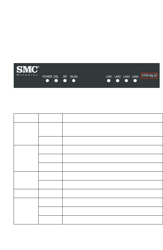
LED Indicators
The ADSL router includes an LED display on the top for system power
and port indications that simplifies installation and network
troubleshooting.
Figure 2-1. Led indicators
LED Status Description
Power On The ADSL router is receiving power. Normal
operation.
Off Power off or failure.
DSL On ADSL connection is functioning correctly.
Flashing The ADSL router is establishing an ADSL link.
Off ADSL connection is not established.
ISP On WAN port connected.
Off No WAN port connection.
WLAN Flashing The WLAN port is sending or receiving data.
LAN1 to
LAN4
On Ethernet connection is established.
Flashing The indicated LAN port is sending or receiving data.
Off There is no LAN connection on the port.
I
NSTALLATION
2-4
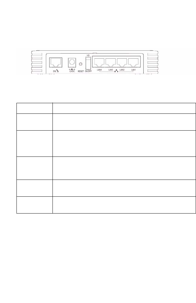
Rear Ports
The ADSL router also provides the following ports on the rear panel:
Figure 2-2. Rear Panel
Item Description
DSL
Port
WAN port (RJ-11). Connect your ADSL line to this port.
Power Inlet Connect the included power adapter to this inlet.
Warning: Using the wrong type of power adapter may damage
the router.
Reset Button Use this button to reset the power and restore the default
factory settings. To reset without losing configuration settings,
see “Reset” on page 4-61.
On/Off
switch
Use this switch to turn the router ON and OFF.
LAN Ports 4 Fast Ethernet ports (RJ-45). Connect devices on your local
area network to these ports (i.e., a PC, hub, or switch).

ISP S
ETTINGS
2-5
ISP Settings
Please collect the following information from your ISP before setting up
the ADSL router:
• ISP account user name and password
• Protocol, encapsulation and VPI/VCI circuit numbers
•DNS server address
• IP address, subnet mask and default gateway (for fixed IP users only)
Connect the System
The ADSL router can be positioned at any convenient location in your
office or home. No special wiring or cooling requirements are needed. You
should, however, comply with the following guidelines:
• Keep the ADSL router away from any heating devices.
• Do not place the ADSL router in a dusty or wet environment.
You should also remember to turn off the power, remove the power cord
from the outlet, and keep your hands dry when you install the ADSL
router.

I
NSTALLATION
2-6
Connecting the ADSL Line
Connect the splitter to the phone line and the phone to the phone port of
the splitter. Using the black RJ-11 cable provided connect the ADSL port
of the ADSL router to the ADSL port of the splitter.
The splitter is required for connecting your ADSL router and phone to the
same phone line. If you have a dedicated phone line for ADSL connect the
ADSL router directly to the phone line.
Note: To prevent high frequency ADSL signals interfering with
telephone calls, each phone must be connected to the same phone
line through a splitter (also known as an ADSL microfilter).
Connecting the network
Using the grey RJ-45 cable provided connect LAN port of the ADSL
router to the network card of your computer or other network device, e.g.,
hub or switch. The corresponding LAN LED will illuminate green to
indicate good link.
Connecting the Power Adapter
Plug the power adapter into the power socket on the rear of the ADSL
router, and the other end into a power outlet. Check the power indicator
on the front panel is lit. If the power i
ndicator is not lit, refer to
“Troubleshooting” on page A-1.
In case of a power input failure, the ADSL router will automatically restart
and begin to operate once the input power is restored.

C
ONNECT THE
S
YSTEM
2-7
Wall Mounting
There are 2 slots on the underside of the ADSL router that can be used for
wall mounting. The distance between the 2 slots is 120 mm.
You will need 2 suitable screws, the diameter would be 5.0 mm to 7.0 mm,
to wall mount the ADSL router.
When wall mounting the unit, ensure that it is within reach of the power
outlet.
To wall mount the unit:
1. Ensure that the wall you use is smooth, flat, dry and sturdy and use the
2 screws holes which both are 120 mm apart.
2. Fix the screws into wall, leaving their heads 5 mm clear of the wall
surface.
3. Remove any connections to the unit and locate it over the screw heads.
When in line, gently push the unit on to the wall and move it
downwards to secure.

3-1
C
HAPTER
3
C
ONFIGURING
C
LIENT
PC
After completing hardware setup by connecting all your network devices,
you need to configure your computer to connect to the ADSL router.
See:
“Windows 2000” on page 3-3
“Windows XP” on page 3-6
or
“Configuring Your Macintosh Computer” on page 3-8
depending on your operating system.

C
ONFIGURING
C
LIENT
PC
3-2
TCP/IP Configuration
To access the Internet through the ADSL router, you must configure the
network settings of the computers on your LAN to use the same IP subnet
as the ADSL router. The default IP settings for the ADSL router are:
IP Address: 192.168.2.1
Subnet Mask: 255.255.255.0
Note: These settings can be changed to fit your network requirements,
but you must first configure at least one computer to access the
ADSL router’s web configuration interface in order to make the
required changes. (See “Configuring the ADSL Router” on page
4-1 for instruction on configuring the ADSL router.)
W
INDOWS
2000
3-3
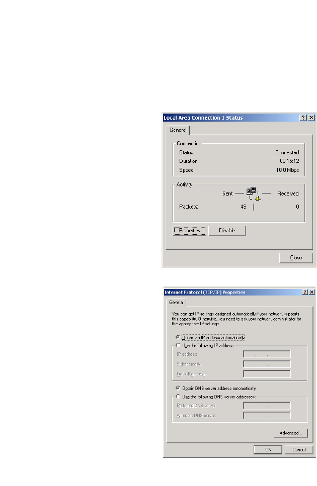
Windows 2000
1. On the Windows desktop, click Start/Settings/Network and Dial-Up
Connections.
2. Click the icon that
corresponds to the
connection to your ADSL
router.
3. The connection status
screen will open. Click
Properties.
4. Double-click Internet
Protocol (TCP/IP).
5. If “Obtain an IP address
automatically” and
“Obtain DNS server
address automatically” are
already selected, your
computer is already
configured for DHCP. If
not, select this option.
C
ONFIGURING
C
LIENT
PC
3-4
Disable HTTP Proxy
You need to verify that the “HTTP Proxy” feature of your web browser is
disabled. This is so that your browser can view the ADSL router’s HTML
configuration pages.
Obtain IP Settings from Your ADSL router
Now that you have configured your computer to connect to your ADSL
router, it needs to obtain new network settings. By releasing old DHCP IP
settings and renewing them with settings from your ADSL router, you can
verify that you have configured your computer correctly.
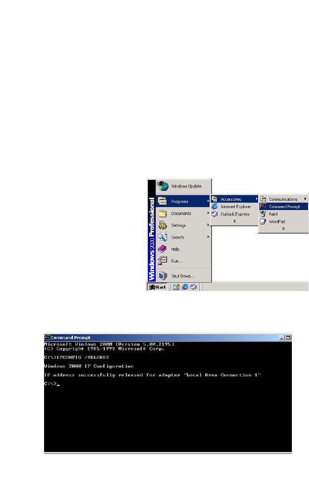
1. On the Windows desktop,
click Start/Programs/
Accessories/Command
Prompt.
2. In the Command Prompt window, type “IPCONFIG/RELEASE”
and press the ENTER key.
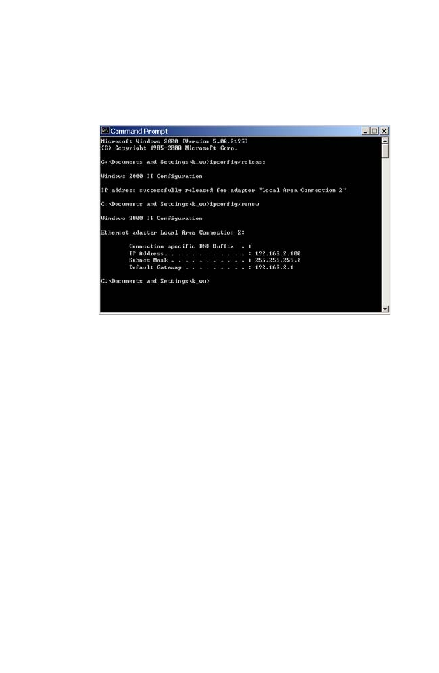
W
INDOWS
2000
3-5
3. Type “IPCONFIG /RENEW” and press the ENTER key. Verify that
your IP Address is now 192.168.2.xxx, your Subnet Mask is
255.255.255.0 and your Default Gateway is 192.168.2.1. These
values confirm that your ADSL Router is functioning.
4. Close the Command Prompt window.
Your computer is now configured to connect to the ADSL router.

C
ONFIGURING
C
LIENT
PC
3-6
Windows XP
1. On the Windows desktop, click Start/Control Panel.
2. In the Control Panel window, click Network and Internet
Connections.
3. The Network Connections window will open. Double-click the
connection for this device.
4. On the connection status screen, click Properties.
5. Double-click Internet Protocol (TCP/IP).
6. If “Obtain an IP address automatically” and “Obtain DNS server
address automatically” are already selected, your computer is already
configured for DHCP. If not, select this option.
Disable HTTP Proxy
You need to verify that the “HTTP Proxy” feature of your web browser is
disabled. This is so that your browser can view the ADSL router’s HTML
configuration pages.
Obtain IP Settings from Your ADSL router
Now that you have configured your computer to connect to your ADSL
router, it needs to obtain new network settings. By releasing old DHCP IP
settings and renewing them with settings from your ADSL router, you can
verify that you have configured your computer correctly.
1. On the Windows desktop, click Start/Programs/Accessories/
Command Prompt.
2. In the Command Prompt window, type “IPCONFIG/RELEASE”
and press the ENTER key.

W
INDOWS
XP
3-7
3. Type “IPCONFIG /RENEW” and press the ENTER key. Verify that
your IP Address is now 192.168.2.xxx, your Subnet Mask is
255.255.255.0 and your Default Gateway is 192.168.2.1. These
values confirm that your ADSL router is functioning.
4. Close the Command Prompt window.
Your computer is now configured to connect to the ADSL router.
C
ONFIGURING
C
LIENT
PC
3-8
Configuring Your Macintosh Computer
You may find that the instructions here do not exactly match your
operating system. This is because these steps and screenshots were created
using Mac OS 10.2. Mac OS 7.x and above are similar, but may not be
identical to Mac OS 10.2.
Follow these instructions:
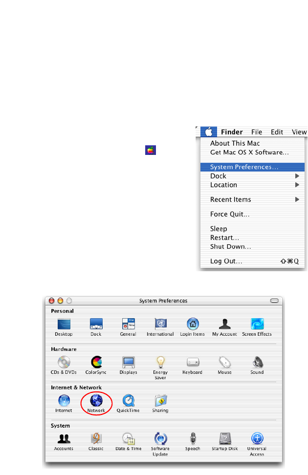
1. Pull down the Apple Menu . Click
System Preferences
2. Double-click the Network icon in the
Systems Preferences window.
C
ONFIGURING
Y
OUR
M
ACINTOSH
C
OMPUTER
3-9
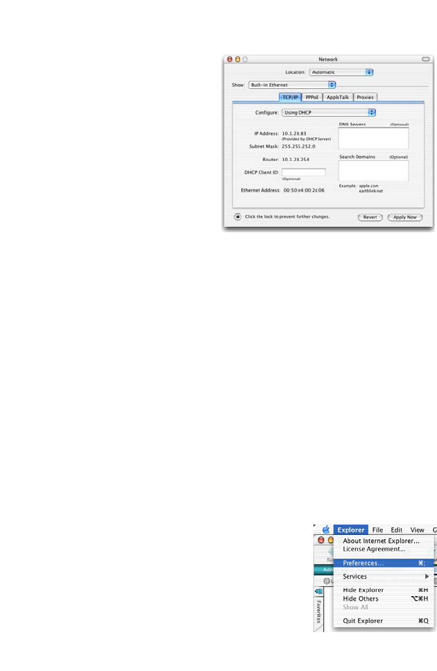
3. If “Using DHCP Server” is
already selected in the
Configure field, your
computer is already
configured for DHCP. If
not, select this Option.
4. Your new settings are shown on the TCP/IP tab. Verify that your IP
Address is now 192.168.2.xxx, your Subnet Mask is
255.255.255.0 and your Default Gateway is 192.168.2.1. These
values confirm that your ADSL router is functioning.
5. Close the Network window.
Now your computer is configured to connect to the ADSL router.
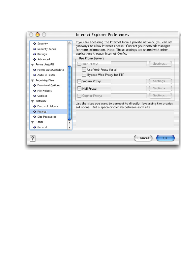
Disable HTTP Proxy
You need to verify that the “HTTP Proxy” feature of your web browser is
disabled. This is so that your browser can view the ADSL router’s HTML
configuration pages. The following steps are for Internet Explorer.
Internet Explorer
1. Open Internet Explorer and click the Stop
button. Click Explorer/Preferences.
2. In the Internet Explorer Preferences window,
under Network, select Proxies.
C
ONFIGURING
C
LIENT
PC
3-10
3. Uncheck all check boxes and click OK.
4-1
C
HAPTER
4
C
ONFIGURING THE
ADSL R
OUTER
After you have configured TCP/IP on a client computer, you can
configure the ADSL router using your web browser. Internet Explorer 5.5
or above, Netscape Navigator, Mozilla, Firefox and Opera are supported.
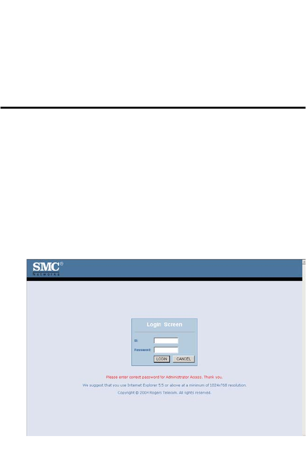
To access the management interface, enter the default IP address of the
ADSL router in your web browser: http://192.168.2.1. Enter the default
login ID: “administrator”, leave the password blank, and click LOGIN.
Note: Passwords can contain from 3~12 alphanumeric characters and
are case sensitive.
C
ONFIGURING THE
ADSL R
OUTER
4-2
Navigating the Management Interface
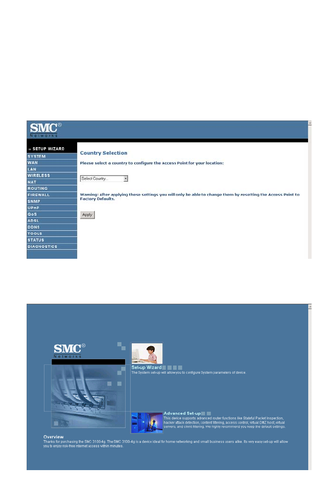
On initial configuration the first screen is Country Selection. Select your
country from the drop-down list. This configures the correct channels for
the wireless AP. The Country Selection screen only appears on initial
configuration or when the ADSL router is reset to factory defaults.
Two items are available on the following screen: Set-up Wizard, and
Advanced Set-up.

N
AVIGATING THE
M
ANAGEMENT
I
NTERFACE
4-3
Use the Setup Wizard for quick and easy configuration of your Internet
connection and basic wireless settings. Go to “Set-up Wizard” on page 4-4
for details.
For Advanced set-up, refer to section “Advanced setup” on page 4-11.
Making Configuration Changes
Configurable parameters have a dialog box or a drop-down menu. Once a
configuration change has been made on a screen, click the APPLY,
SAVE SETTINGS or NEXT button on the screen to enable the new
setting.
Note: To ensure proper screen refresh after a command entry, be sure
that Internet Explorer 5.5 is configured as follows: Under the
menu Tools/Internet Options/General/Temporary Internet
Files/Settings, the setting for “Check for newer versions of stored
pages” should be “Every visit to the page.”
C
ONFIGURING THE
ADSL R
OUTER
4-4
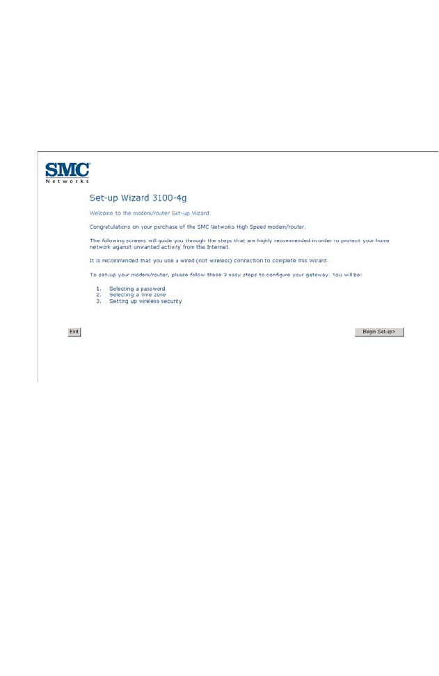
Set-up Wizard
The set-up wizard is designed to help you to quickly and easily configure
your ADSL router. Follow the instruction on the screen, and click Begin
set-up.
S
ET
-
UP
W
IZARD
4-5
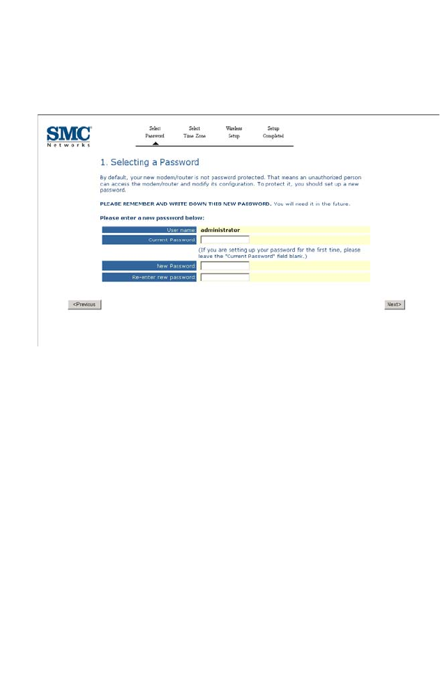
Selecting a Password
By default, the ADSL router comes with no password. For security
reasons, you should set up a new password.
• The user name is “administrator” by default.
• Current password: by default, there is no password.
• New password: enter the new password in this field.
• Enter the new password again in the re-enter the password field.
C
ONFIGURING THE
ADSL R
OUTER
4-6
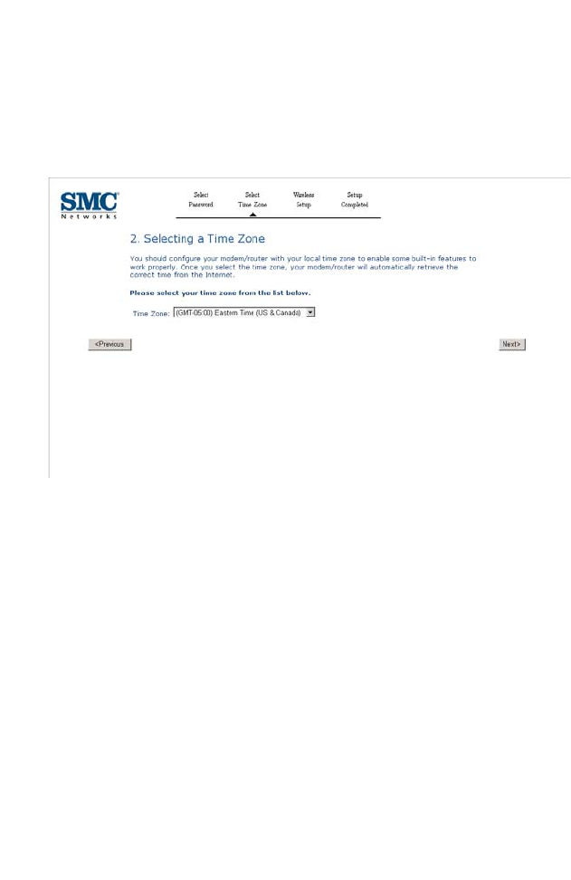
Selecting a Time Zone
To keep the time on the router correct, select your local time zone from
the drop-down menu. This information is used for log entries and client
filtering.
Click NEXT to continue.
S
ET
-
UP
W
IZARD
4-7
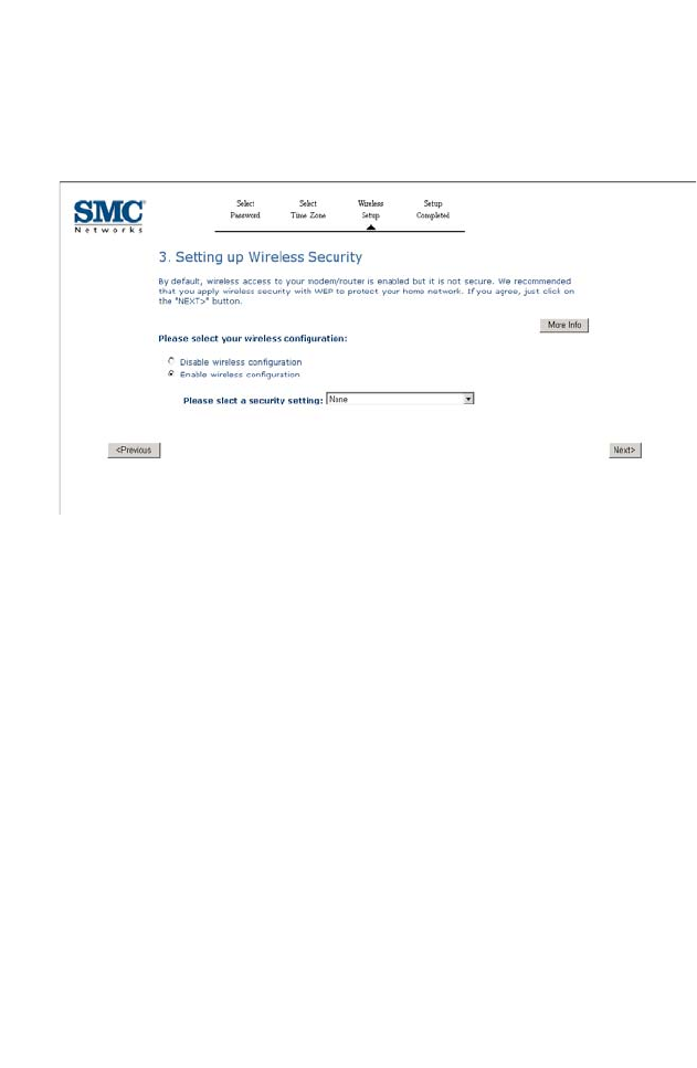
Setting up Wireless Security
This screen allows you to configure the wireless security. The ADSL router
supports WEP and WPA.
• Select Disable/Enable wireless configuration, if you disable wireless
configuration, there is no need to setup the security function. If you
select Enable wireless configuration, then select the security settings
from the drop-down menu.
For WEP security function, go to next page.
For WPA security function, go to page 4-9.
Click NEXT to continue.
C
ONFIGURING THE
ADSL R
OUTER
4-8
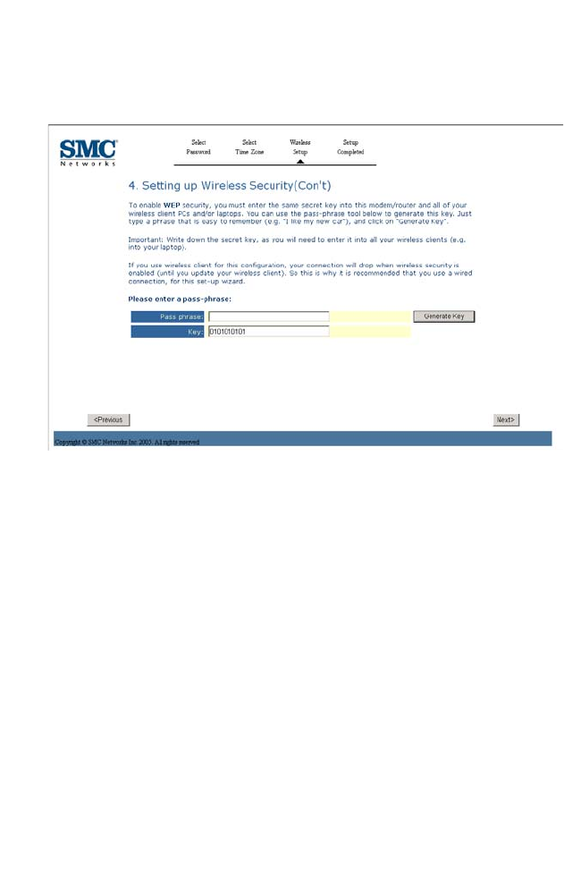
WEP_Security
Choosing WEP as the wireless security for your wireless network.
Enter a string in the passphrase field, then click Generate Key.
Click Next to continue. The Set-up complete screen will then appear.
S
ET
-
UP
W
IZARD
4-9
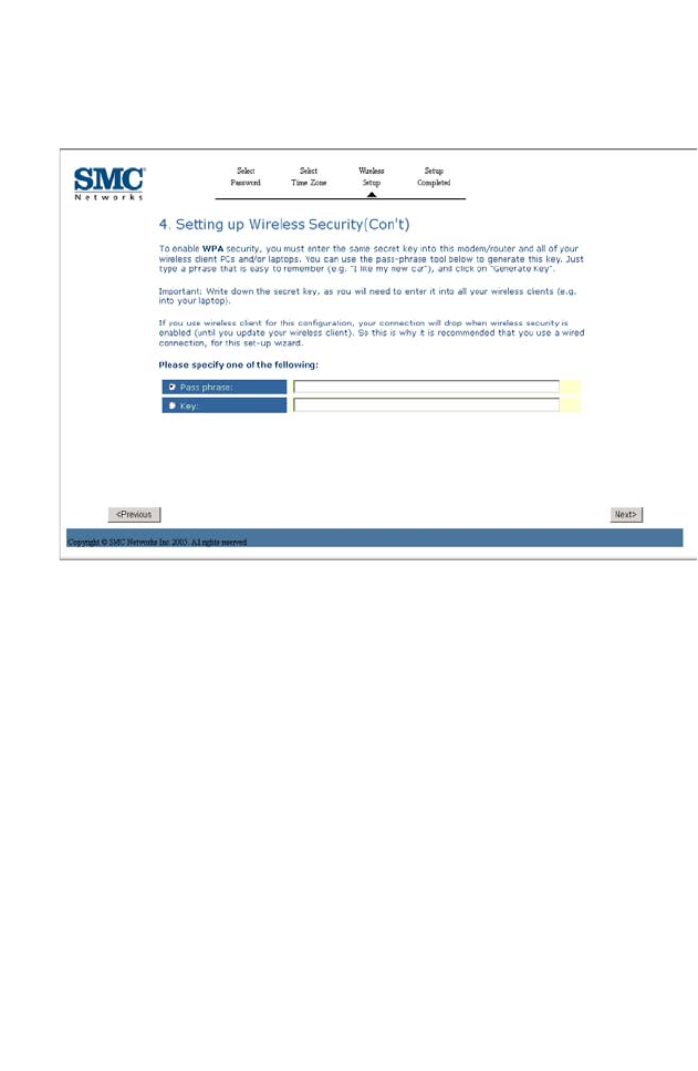
WPA_Security
Choosing WPA as the security mechanism for your wireless network.
you can select to use the passphrase function or encryption key as the
security method, then enter the string in the corresponding field.
Click Next to complete this setup.
C
ONFIGURING THE
ADSL R
OUTER
4-10
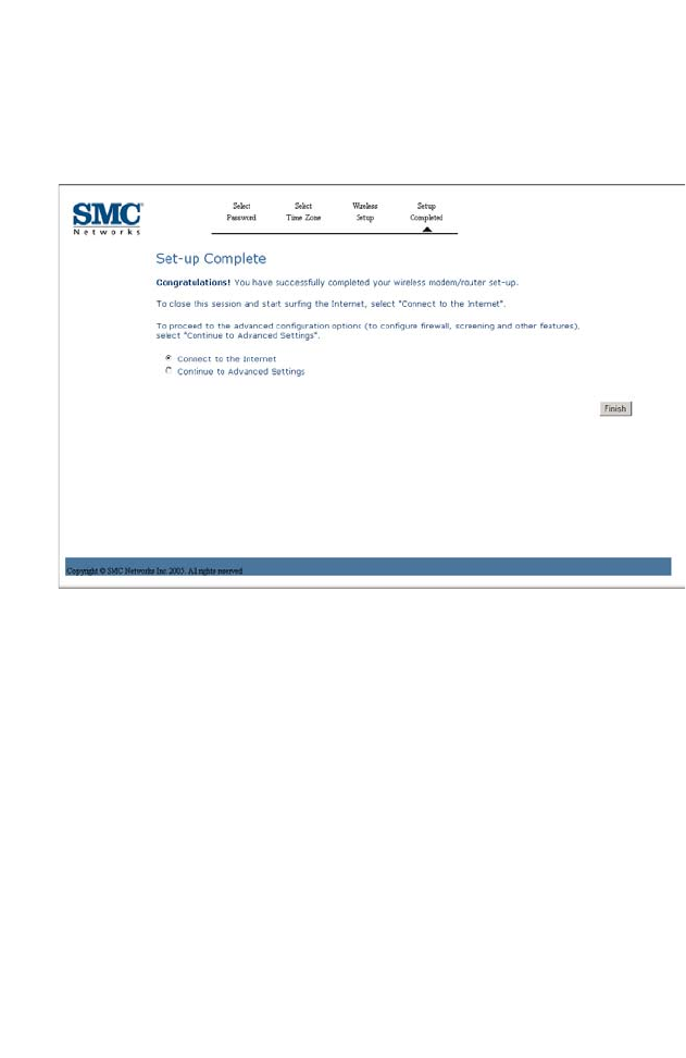
Wizard_Setup Complete
This screen shows that you have configured your ADSL router using the
Setup Wizard.
• Connect to the Internet: select this option, and then click Finish to
connect to the internet.
• Continue to Advanced Settings: select this option, and then click
Finish to continue with more configurations for the ADSL router.
A
DVANCED SETUP
4-11
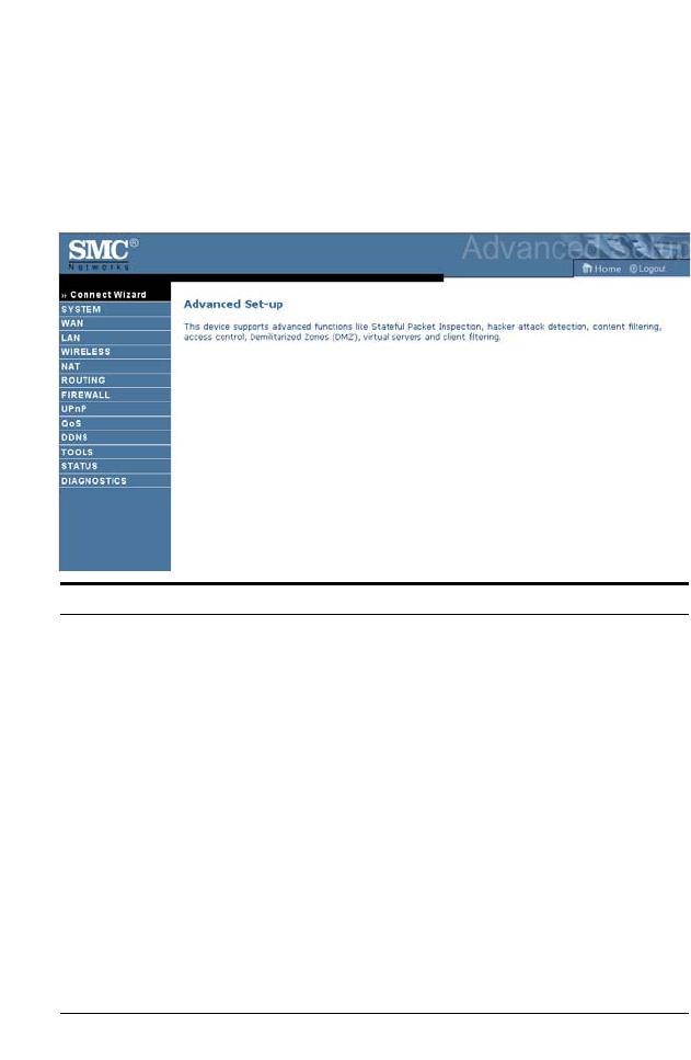
Advanced setup
The left-hand side displays the main menu and the right-hand side shows
descriptive information. There are 13 main menu items as described in the
following table.
Menu Description
System Sets the local time zone, the password for administrator access, and
the IP address of a PC that will be allowed to manage the ADSL
router remotely.
WAN Specifies the Internet connection settings.
LAN Sets the TCP/IP configuration for the ADSL router LAN interface
and DHCP clients.
Wireless Configures the radio frequency, SSID, and security for wireless
communications.
NAT Configures Address Mapping, virtual server and special
applications.
Routing Sets the routing parameters and displays the current routing table.
Firewall Configures a variety of security and specialized functions including:
Access Control, URL blocking, Internet access control scheduling,
intruder detection, and DMZ.
UPnP Enables the Universal Plug and Play function.

C
ONFIGURING THE
ADSL R
OUTER
4-12
QoS Allows you to prioritize your network traffic.
DDNS Configures Dynamic DNS function.
Tools Contains options to ping network connection, trace route, backup
& restore the current configuration, restore all configuration
settings to the factory defaults, update system firmware, or reset the
system.
Status Provides WAN connection type and status, firmware and hardware
version numbers, system IP settings, as well as DHCP, NAT, and
firewall information. Displays the number of attached clients, the
firmware versions, the physical MAC address for each media
interface, and the hardware version and serial number. Shows the
security and DHCP client log.
Diagnostics This function is used to diagnose the connection.
Menu Description
A
DVANCED SETUP
4-13
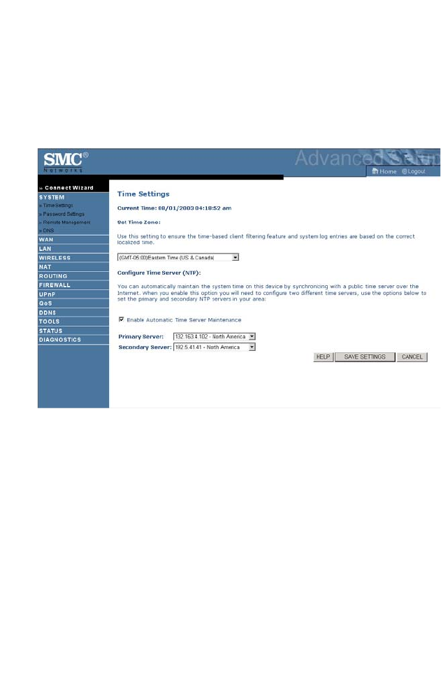
System
Time Settings
Select your local time zone from the drop-down menu. This information is
used for log entries and client filtering.
If you want to automatically synchronize the ADSL router with a public
time server, check the Enable Automatic Time Server
Maintenance check box.Then select the desired servers from the
drop-down menus.
C
ONFIGURING THE
ADSL R
OUTER
4-14
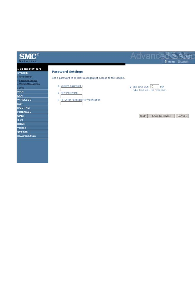
Password Settings
Use this screen to change the password for accessing the management
interface.
Passwords can contain from 3~12 alphanumeric characters and are case
sensitive.
Note: If you lost the password, or you cannot gain access to the user
interface, press the blue reset button on the rear panel, holding it
down for at least five seconds to restore the factory defaults. By
default, there is no password.
Enter a maximum Idle Time Out (in minutes) to define a maximum period
of time for which the login session is maintained during inactivity. If the
connection is inactive for longer than the maximum idle time, it will
perform system logout, and you have to log in again to access the
management interface. (Default: 10 minutes)
A
DVANCED SETUP
4-15
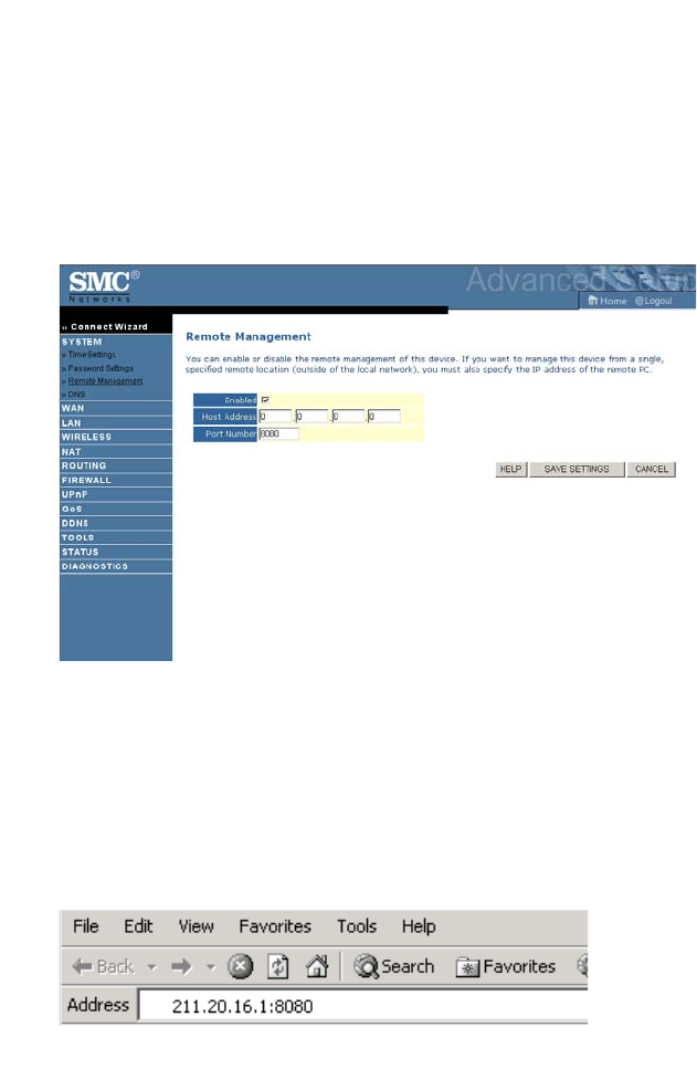
Remote Management
By default, management access is only available to users on your local
network. However, you can also manage the ADSL router from a remote
host by entering the IP address of a remote computer on this screen.
Check the Enabled check box, and enter the IP address of the remote
host and click SAVE SETTINGS.
Note: If you check Enabled and specify an IP address of 0.0.0.0, any
remote host can manage the ADSL router.
For remote management via WAN IP address you need to connect using
port 8080. Simply enter WAN IP address followed by:8080, for example,
211.20.16.1:8080.
C
ONFIGURING THE
ADSL R
OUTER
4-16
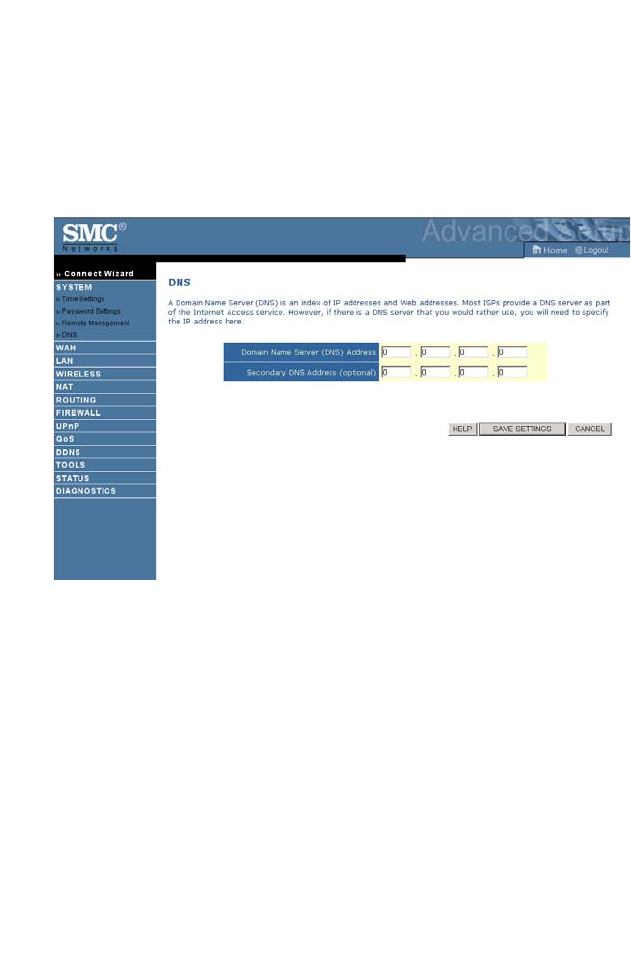
DNS
A Domain Name Server (DNS) is an index of IP addresses and web
addresses. Most ISPs provide a DNS server as part of the Internet access
service. However, if there is a DNS server that you would rather use, you
will need to specify the IP address here.
A
DVANCED SETUP
4-17
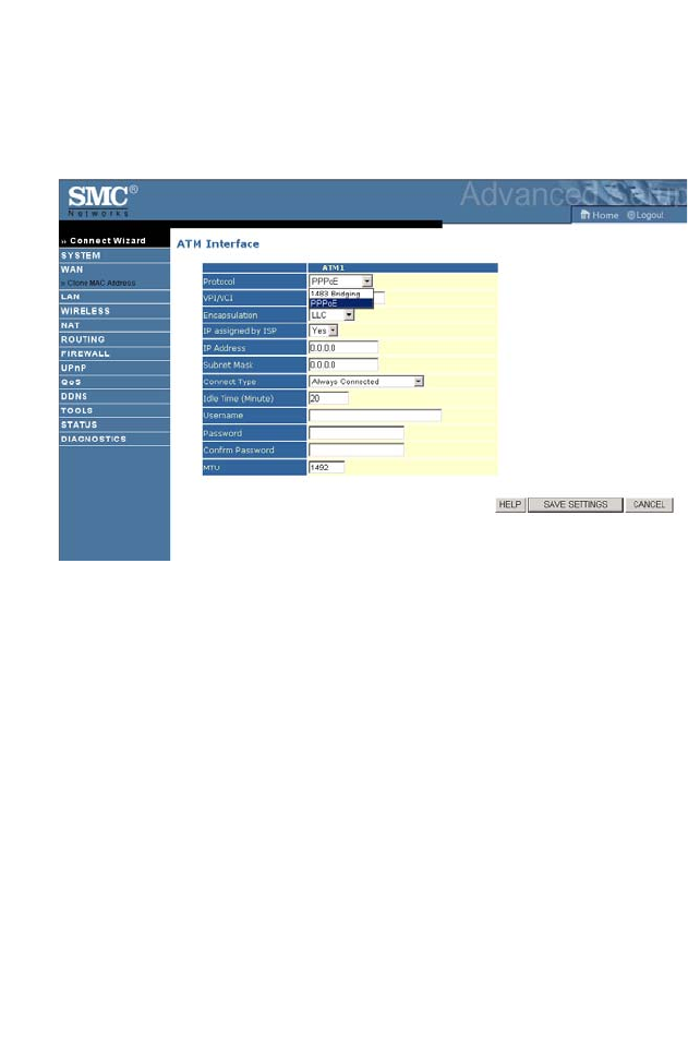
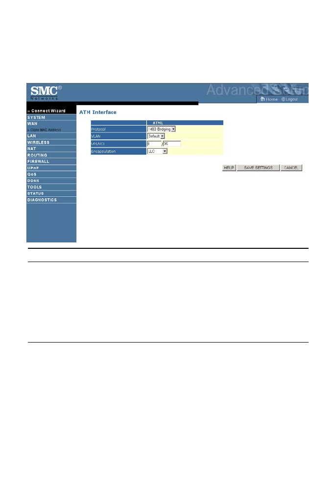
WAN
Specify the WAN connection parameters provided by your Internet
Service Provider (ISP).
The following protocols are supported:
• 1483 Bridging
•PPPoE
C
ONFIGURING THE
ADSL R
OUTER
4-18
ATM Interface
1483 Bridging
Enter the Bridging settings provided by your ISP.
Parameter Description
VLAN Select VLAN group from the drop-down menu.
New VLAN groups can be created from the LAN
menu.
VPI/VCI Enter the Virtual Path Identifier (VPI) and Virtual
Circuit Identifier (VCI) supplied by your ISP.
Encapsulation Select the encapsulation used by ISP from the
drop-down menu.
A
DVANCED SETUP
4-19
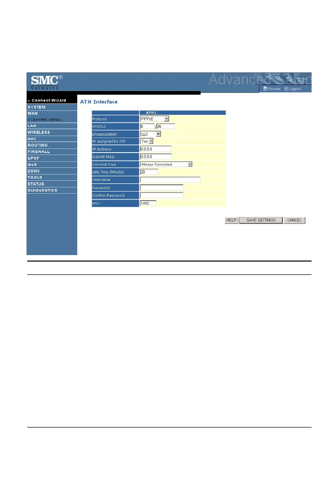
PPPoE
Enter the PPPoE settings provided by your ISP.
Parameter Description
VPI/VCI Enter the Virtual Path Identifier (VPI) and Virtual
Circuit Identifier (VCI) supplied by your ISP.
Encapsulation Select the encapsulation used by ISP from the
drop-down menu.
IP assigned
by ISP
Select Yes if you have a dynamic IP address. Select
No if you have a static IP address.
IP Address Enter the IP address provided by your ISP. For
dynamic IP, leave this field blank.
Subnet Mask Enter the Subnet Mask address provided by your ISP.
For dynamic IP, leave this field blank.
Connect Type Sets connection mode to Always connected,
Auto-Triggered by traffic or Manual connection.
For flat rate services use Always connected.
C
ONFIGURING THE
ADSL R
OUTER
4-20
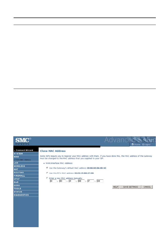
Clone MAC Address
Some ISPs require you to register your MAC address with them. If this is
the case, the MAC address of the ADSL router must be changed to the
MAC address that you have registered with your ISP.
Idle Time (Minute) Enter the maximum idle time for the Internet
connection. After this time has been exceeded the
connection will be terminated. This setting only
applies when the Connect Type is set to
Auto-Triggered by traffic.
Username Enter user name provided by your ISP.
Password Enter password provided by your ISP.
Confirm
Password
Confirm password.
MTU Leave the Maximum Transmission Unit (MTU) at the
default value unless instructed by your ISP.
Parameter Description
A
DVANCED SETUP
4-21
LAN
Use the LAN menu to configure the LAN IP address, VLAN binding and
to enable the DHCP server for dynamic client address allocation.
Parameter Description
LAN IP
IP Address The IP address of the router.
IP Subnet Mask The subnet mask of the network.
VLAN Binding
LAN1 to
LAN4
Select VLAN group for the corresponding LAN
port. By default all ports members of the Default
VLAN.
DHCP Server
DHCP Server Enable or Disable the DHCP server function. By
default the DHCP server is enabled for automatic IP
address assignment to client devices.
DHCP Option 60
Vendor ID
Enter the ID in this field.

C
ONFIGURING THE
ADSL R
OUTER
4-22
Lease Time Set the IP lease time. For home networks this may be
set to Forever, which means there is no time limit on
the IP address lease.
IP Address Pool
Start IP Address Specify the start IP address of the DHCP pool. Do
not include the IP address of the ADSL router in the
client address pool. If you change the pool range,
make sure the first three octets match the gateway’s
IP address, i.e., 192.168.2.xxx.
End IP Address Specify the end IP address of the DHCP pool.
Domain Name If your network uses a domain name, enter it here.
Otherwise, leave this field blank.
IP assignment based
on MAC
You can assign a specific IP address to a specific
MAC address. Enter the matching IP address and
MAC address on the table.
Parameter Description
A
DVANCED SETUP
4-23
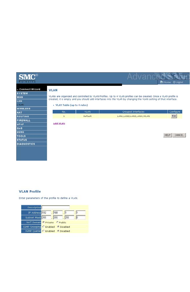
VLAN
VLANs are organized and controlled by VLAN Profiles. Up to 4 VLAN
profiles can be created. Once a VLAN profile is created, you should add
interfaces into the VLAN by changing the VLAN setting of that interface.
Please note that only those interfaces of IEEE 802 bridging type (ex. LAN
ports and 1483 Bridging PVCs) can be added to a VLAN.
Click Add VLAN to setup the profile.
• Description: enter a name or description for the VLAN.
• IP Address: enter the IP address.
• Subnet Mask: enter the subnet mask.

C
ONFIGURING THE
ADSL R
OUTER
4-24
• NAT Domain: select private or public.
• IGMP Snooping: Internet Group Management Protocol (IGMP)
snooping is a method by which Layer 2 devices can “listen in” on
IGMP conversations between hosts and routers. When a switch hears
a group join message from a host, it notes which switch interface it
heard the message on, and adds that interface to the group. Similarly,
when a Layer 2 switch hears a group leave message or a response timer
expires, the switch will remove that host’s switch interface from the
group.
• IGMP Querier: if the IGMP Querier is enabled, then the router will
periodically query all multicast group members on the specified
VLAN.
A
DVANCED SETUP
4-25
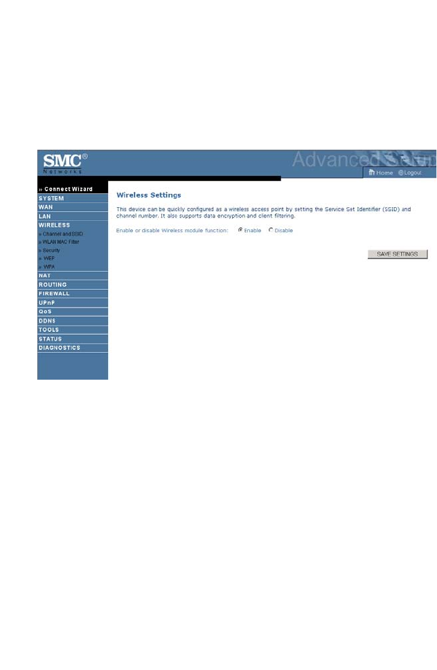
Wireless
The ADSL router also operates as a wireless access point, allowing wireless
computers to communicate with each other. To configure this function, all
you need to do is enable the wireless function, define the radio channel,
the SSID, and the security options.
• Enable or disable Wireless module function: check Enable and then
click SAVE SETTINGS.
C
ONFIGURING THE
ADSL R
OUTER
4-26
Channel and SSID
You must specify a common radio channel and SSID (Service Set ID) to
be used by the ADSL router and all of its wireless clients. Be sure you
configure all of its clients to the same values.
Parameter Description
SSID Service Set ID (SSID) is the name given to the wireless
network. The SSID must be the same on the ADSL router
and all of its wireless clients.
SSID
Broadcast
Enable or disable the broadcasting of the SSID. Disabling
broadcasting of the SSID provides added security by hiding
your wireless network.
Wireless
Mode
This device supports both 11g and 11b wireless networks.
Make your selection depending on the type of wireless
network that you have.
Channel The radio channel used by the wireless router and its clients
to communicate with each other. This channel must be the
same on the ADSL router and all of its wireless clients.
The ADSL router will automatically assign itself a radio
channel, or you may select one manually.
A
DVANCED SETUP
4-27
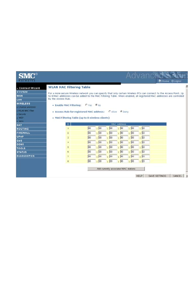
WLAN MAC Filter
Using this MAC filter functionality, you can restrict wireless access based
on MAC address. Each PC has a unique identifier known as a Medium
Access Control (MAC) address. With MAC filtering enabled, the
computers whose MAC address you have listed in the filtering table will be
able to connect (or will be denied access) to the ADSL router.
• Enable MAC Filtering: select to turn on/off this feature.
• Access Rule for registered MAC address: select to allow/deny access
for the registered MAC addresses. Selecting Allow means only MAC
addresses registered here will be able to connect to the router.
Selecting Deny means only the MAC addresses registered here will be
denied access to the router.
• MAC Filtering table: enter the MAC address in the table, or you can
use the option to quickly copy the currently associated client entry to
the MAC Filtering table.
C
ONFIGURING THE
ADSL R
OUTER
4-28
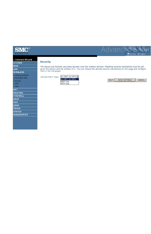
Security
To make your wireless network safe, you should turn on the security
function. The ADSL router supports WEP (Wired Equivalent Privacy),
WPA (Wi-Fi Protected).
Three options are available:
•No WEP, No WPA
• WEP only
• WPA only
A
DVANCED SETUP
4-29
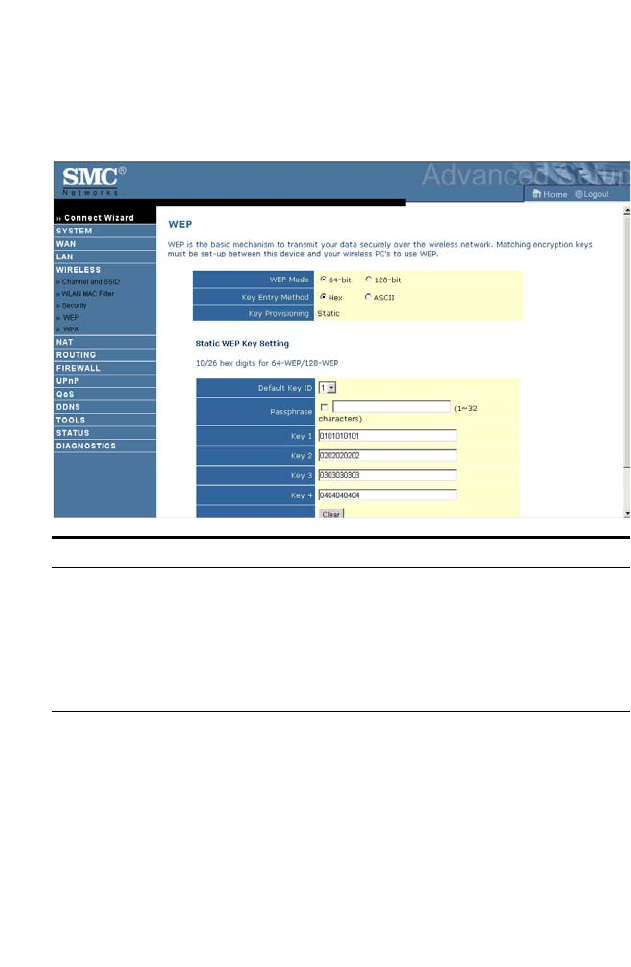
WEP
If you want to use WEP to protect your wireless network, you need to set
the same parameters for the ADSL router and all your wireless clients.
When the key entry method is set to Hex, you can automatically generate
encryption keys using the passphrase or manually enter the keys. To
generate the keys using passphrase, check the box, enter a string of text,
and click GENERATE. Select the default key from the drop-down menu
and click SAVE SETTINGS.
Parameter Description
WEP Mode Select 64 bit or 128 bit key to use for encryption.
Key
Entry Method
Select Hex or ASCII to use for encryption key
Key
Provisioning
Select Static if there is only one fixed key for encryption. If
you want to select Dynamic, you would need to enable
802.1X function first.

C
ONFIGURING THE
ADSL R
OUTER
4-30
Before saving settings the key is shown in clear text. If your wireless client
does not have a passphrase utility, make a note of the default key before
saving settings. This is so you can configure your wireless client with the
correct key.
To manually configure the encryption key, enter five hexadecimal pairs of
digits for each 64-bit key, or enter 13 pairs for the single 128-bit key.
(A hexadecimal digit is a number or letter in the range 0-9 or A-F.)
Note that WEP protects data transmitted between wireless nodes, but
does not protect any transmissions over your wired network or over the
Internet.
Note: The passphrase can consist of up to 32 alphanumeric characters.
A
DVANCED SETUP
4-31
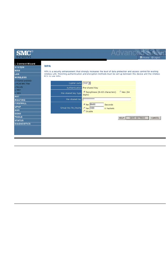
WPA
Wi-Fi Protected Access (WPA) combines temporal key integrity protocol
(TKIP) and 802.1X mechanisms. It provides dynamic key encryption and
802.1X authentication service.
Parameter Description
Cypher suite TKIP is the security mechanism used in WPA for
encryption.
Authentication Pre-shared key: for the SOHO network environment
without an authentication server.
Pre-shared
key type
Select the key type to be used in the Pre-shared Key.
Pre-shared Key Type in the key here.
Group Key
Re_Keying
The period of renewing broadcast/multicast key.
C
ONFIGURING THE
ADSL R
OUTER
4-32
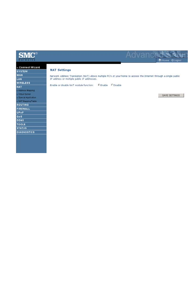
NAT
Network Address Translation allows multiple users to access the Internet
sharing one public IP.
• Enable or disable NAT module function: select to turn on/turn off
this function.
A
DVANCED SETUP
4-33
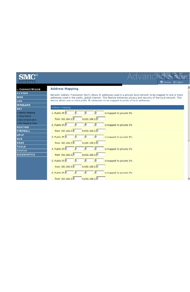
Address Mapping
Allows one or more public IP addresses to be shared by multiple internal
users. This also hides the internal network for increased privacy and
security. Enter the Public IP address you wish to share into the Global IP
field. Enter a range of internal IPs that will share the global IP into the
“from” field.
C
ONFIGURING THE
ADSL R
OUTER
4-34
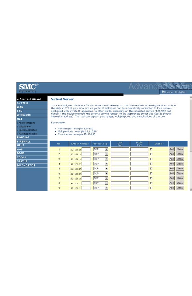
Virtual Server
If you configure the ADSL router as a virtual server, remote users
accessing services such as web or FTP at your local site via public IP
addresses can be automatically redirected to local servers configured with
private IP addresses. In other words, depending on the requested service
(TCP/UDP port number), the ADSL router redirects the external service
request to the appropriate server (located at another internal IP address).
For example, if you set Type/Public Port to TCP/80 (HTTP or web) and
the Private IP/Port to 192.168.2.2/80, then all HTTP requests from
outside users will be transferred to 192.168.2.2 on port 80. Therefore, by
just entering the IP address provided by the ISP, Internet users can access
the service they need at the local address to which you redirect them.
The more common TCP service ports include:
HTTP: 80, FTP: 21, Telnet: 23, and POP3: 110.
A list of ports is maintained at the following link:
http://www.iana.org/assignments/port-numbers.
A
DVANCED SETUP
4-35
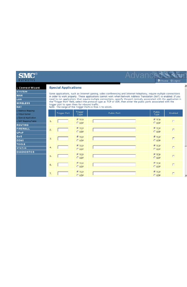
Special Application
Some applications require multiple connections, such as Internet gaming,
video-conferencing, and Internet telephony. These applications may not
work when Network Address Translation (NAT) is enabled. If you need to
run applications that require multiple connections, use these screens to
specify the additional public ports to be opened for each application.
C
ONFIGURING THE
ADSL R
OUTER
4-36
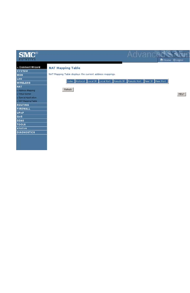
NAT Mapping Table
This screen displays the current NAPT (Network Address Port
Translation) address mappings.
A
DVANCED SETUP
4-37
Routing
These screens define routing related parameters, including static routes and
RIP (Routing Information Protocol) parameters.
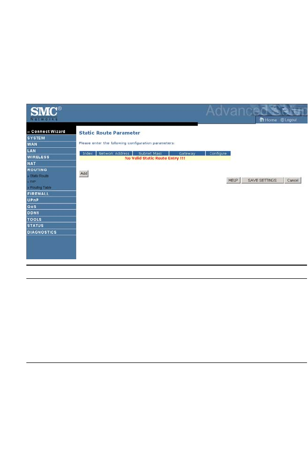
Static Route
Click Add to add a new static route to the list, or check the box of an
already entered route and click Modify. Clicking Delete will remove an
entry from the list.
Parameter Description
Index Check the box of the route you wish to delete or modify.
Network Address Enter the IP address of the remote computer for which
to set a static route.
Subnet Mask Enter the subnet mask of the remote network for which
to set a static route.
Gateway Enter the WAN IP address of the gateway to the remote
network.
C
ONFIGURING THE
ADSL R
OUTER
4-38
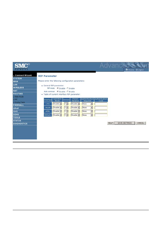
RIP
RIP sends routing-update messages at regular intervals and when the
network topology changes. When a router receives a routing update that
includes changes to an entry, it updates its routing table to reflect the new
route. RIP routers maintain only the best route to a destination. After
updating its routing table, the router immediately begins transmitting
routing updates to inform other network routers of the change.
Parameter Description
General RIP Parameters
RIP mode Globally enables or disables RIP.
Auto summary If Auto summary is disabled, then RIP packets will
include sub-network information from all sub-
networks connected to the router.
If enabled, this sub-network information will be
summarized to one piece of information covering
all sub-networks.
Table of current
Interface RIP parameter
Interface The WAN interface to be configured.

A
DVANCED SETUP
4-39
Operation Mode Disable: RIP disabled on this interface.
Enable: RIP enabled on this interface.
Silent: Listens for route broadcasts and updates its
route table. It does not participate in sending route
broadcasts.
Version Sets the RIP (Routing Information Protocol)
version to use on this interface.
Poison Reverse A method for preventing loops that would cause
endless retransmission of data traffic.
Authentication Required • None: No authentication.
• Password: A password authentication key is
included in the packet. If this does not match
what is expected, the packet will be discarded.
This method provides very little security as it
is possible to learn the authentication key by
watching RIP packets.
• MD5: An algorithm that is used to verify data
integrity through the creation of a 128-bit
message digest from data input (which may
be a message of any length) that is claimed to
be as unique to that specific data as a
fingerprint is to a specific individual.
Authentication Code Password or MD5 Authentication key.
Parameter Description
C
ONFIGURING THE
ADSL R
OUTER
4-40
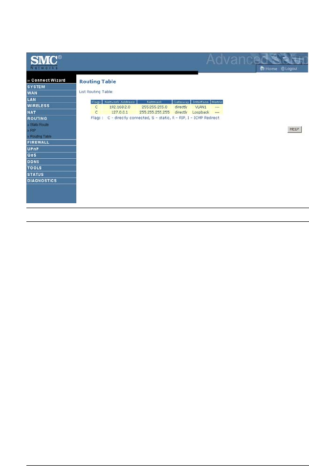
Routing Table
Parameter Description
Flags Indicates the route status:
C = Direct connection on the same subnet.
S = Static route.
R = RIP (Routing Information Protocol) assigned route.
I = ICMP (Internet Control Message Protocol) Redirect route.
Network
Address
Destination IP address.
Netmask The subnetwork associated with the destination.
This is a template that identifies the address bits in the destination
address used for routing to specific subnets. Each bit that corresponds
to a “1” is part of the subnet mask number; each bit that corresponds
to “0” is part of the host number.
Gateway The IP address of the router at the next hop to which frames are
forwarded.
Interface The local interface through which the next hop of this route is
reached.
Metric When a router receives a routing update that contains a new or
changed destination network entry, the router adds 1 to the metric
value indicated in the update and enters the network in the routing
table.
A
DVANCED SETUP
4-41
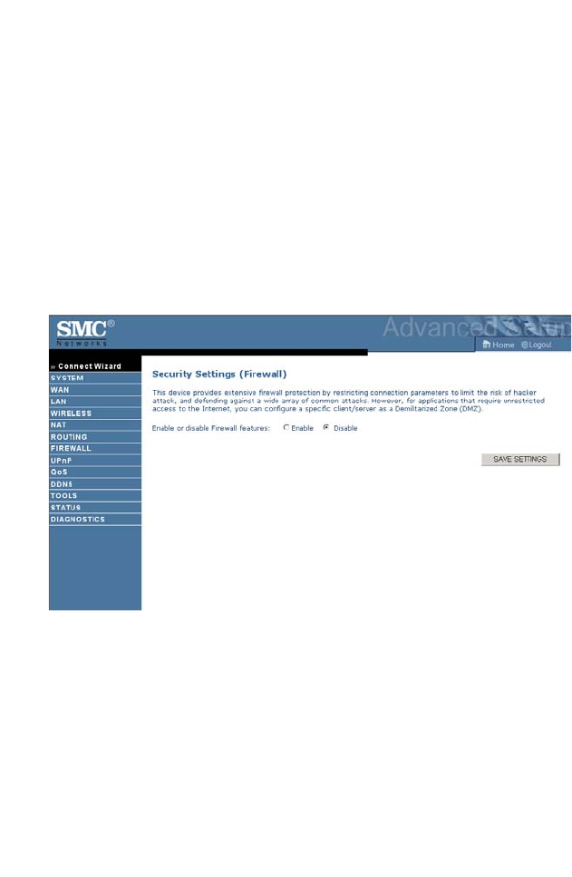
Firewall
The ADSL router’s firewall inspects packets at the application layer,
maintains TCP and UDP session information including time-outs and the
number of active sessions, and provides the ability to detect and prevent
certain types of network attacks.
Network attacks that deny access to a network device are called
Denial-of-Service (DoS) attacks. DoS attacks are aimed at devices and
networks with a connection to the Internet. Their goal is not to steal
information, but to disable a device or network so users no longer have
access to network resources.
The ADSL router protects against the following DoS attacks: IP Spoofing,
Land Attack, Ping of Death, IP with zero length, Smurf Attack, UDP port
loopback, Snork Attack, TCP null scan, and TCP SYN flooding.
(For details see page 4-48.)
The firewall does not significantly affect system performance, so we advise
leaving it enabled to protect your network. Select Enable and click the
SAVE SETTINGS button to open the Firewall submenus.
C
ONFIGURING THE
ADSL R
OUTER
4-42
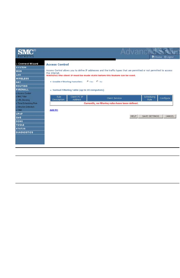
Access Control
Access Control allows users to define the outgoing traffic permitted or
not-permitted through the WAN interface.
Parameter Description
Enable Filtering
Function
Click Yes to turn on the filtering function.
Normal Filtering
Table
Displays a summary of the filtering rules configured.
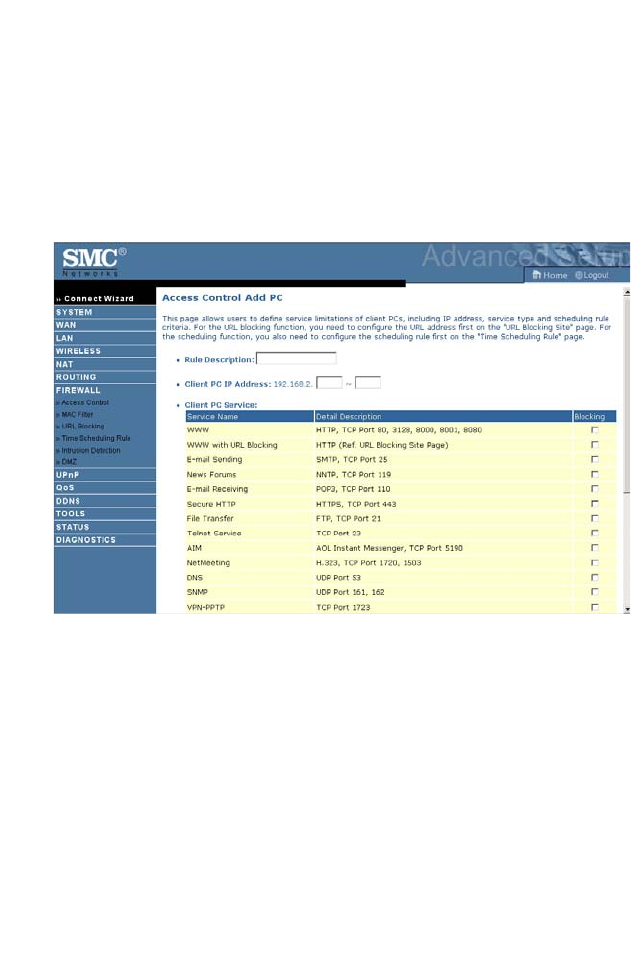
A
DVANCED SETUP
4-43
To add the PC to the filtering table:
1. Click Add PC on the Access Control screen.
2. Define the appropriate settings for client PC services.
3. Click OK and then click SAVE SETTINGS to save your settings.
C
ONFIGURING THE
ADSL R
OUTER
4-44
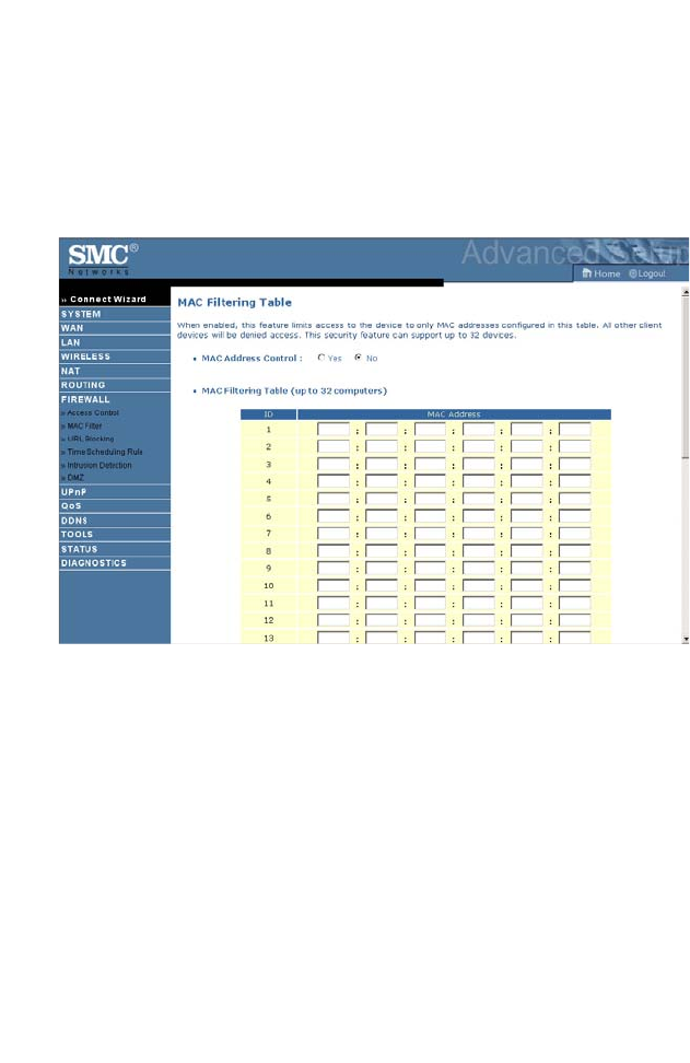
MAC Filter
The ADSL router can also limit the access of hosts within the local area
network (LAN). The MAC Filtering Table allows the ADSL router to enter
up to 32 MAC addresses that are not allowed access to the WAN port.
Please note that this filter only applies to ethernet clients.
• Click Yes to enable, or No to disable this function.
• Enter the MAC address in the space provided.
A
DVANCED SETUP
4-45
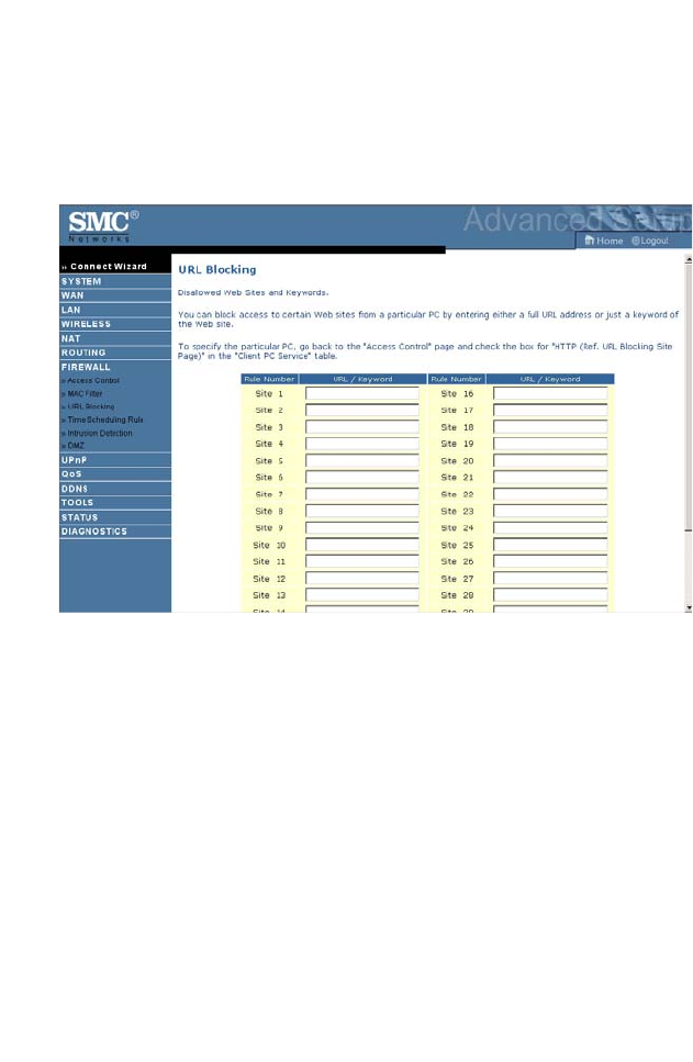
URL Blocking
The ADSL router allows the user to block access to web sites by entering
either a full URL address or just a keyword. This feature can be used to
protect children from accessing violent or pornographic web sites.
You can define up to 30 sites here.
C
ONFIGURING THE
ADSL R
OUTER
4-46
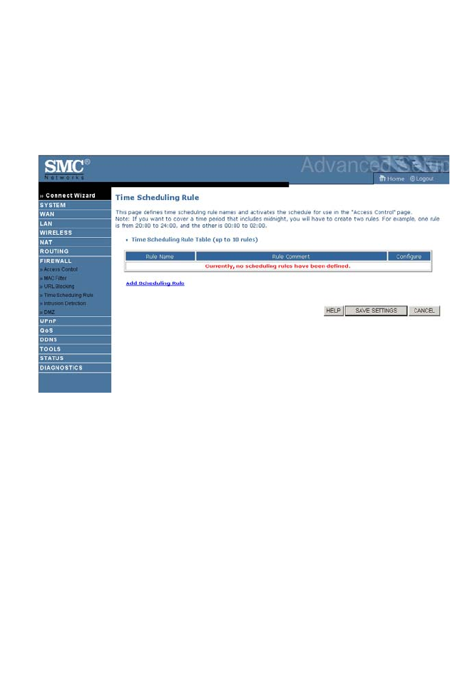
Time Scheduling Rule
You may filter Internet access for local clients based on rules. Each access
control rule may be activated at a scheduled time. Define the schedule on
the Time Scheduling Rule screen, and apply the rule on the Access Control
screen.

A
DVANCED SETUP
4-47
Follow these steps to add a schedule rule:
1. Click Add Scheduling Rule on the Time schedule rule screen.
2. Define the appropriate settings for a schedule rule.
3. Click OK and then click SAVE SETTINGS to save your settings.
C
ONFIGURING THE
ADSL R
OUTER
4-48
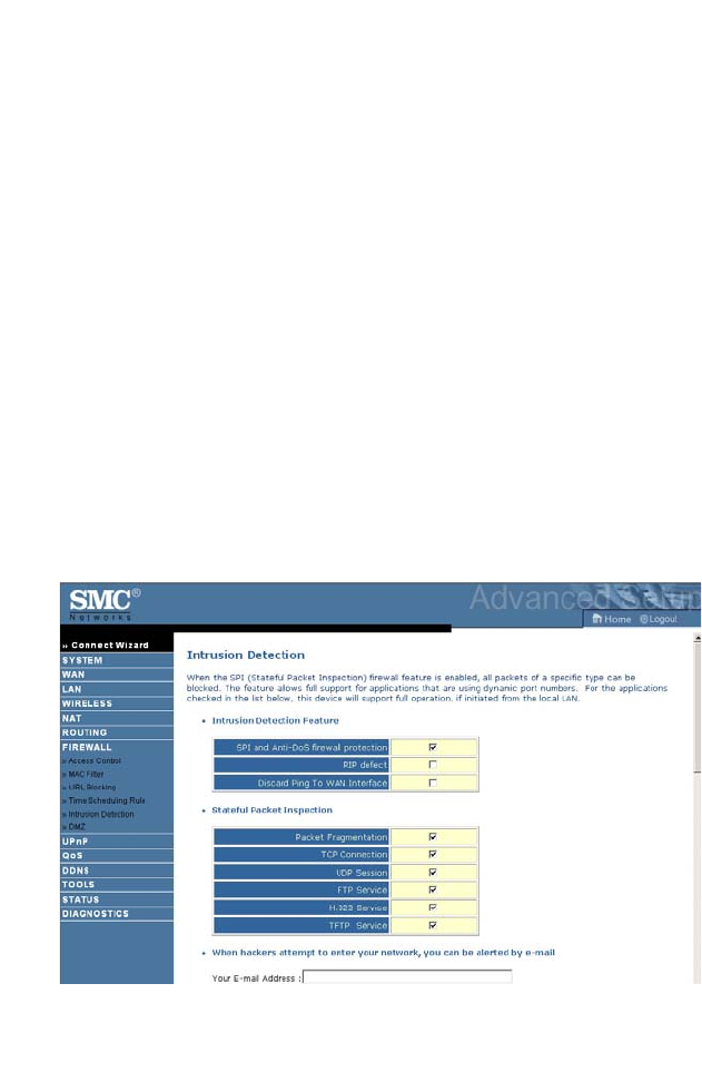
Intrusion Detection
•Intrusion Detection Feature
Stateful Packet Inspection (SPI) and Anti-DoS firewall protection
(Default: enabled) — The Intrusion Detection Feature of the ADSL router
limits access for incoming traffic at the WAN port. When the SPI feature
is turned on, all incoming packets will be blocked except for those types
marked in the Stateful Packet Inspection section.
RIP Defect (Default: disabled) — If an RIP request packet is not
acknowledged to by the router, it will stay in the input queue and not be
released. Accumulated packets could cause the input queue to fill, causing
severe problems for all protocols. Enabling this feature prevents the
packets from accumulating.
Discard Ping to WAN (Default: disabled) — Prevent a ping on the WAN
port of the ADSL router from being routed to the network.
Scroll down to view more information.
A
DVANCED SETUP
4-49

C
ONFIGURING THE
ADSL R
OUTER
4-50
•Stateful Packet Inspection
This is called a “stateful” packet inspection because it examines the
contents of the packet to determine the state of the communications; i.e., it
ensures that the stated destination computer has previously requested the
current communication. This is a way of ensuring that all communications
are initiated by the recipient computer and are taking place only with
sources that are known and trusted from previous interactions. In addition
to being more rigorous in their inspection of packets, stateful inspection
firewalls also close off ports until connection to the specific port is
requested.
When particular types of traffic are checked, only the particular type of
traffic initiated from the internal LAN will be allowed. For example, if the
user only checks “FTP Service” in the Stateful Packet Inspection section,
all incoming traffic will be blocked except for FTP connections initiated
from the local LAN.
Stateful Packet Inspection allows you to select different application types
that are using dynamic port numbers. If you wish to use the Stateful Packet
Inspection (SPI) to block packets, click on the Yes radio button in the
“Enable SPI and Anti-DoS firewall protection” field and then check the
inspection type that you need, such as Packet Fragmentation, TCP
Connection, UDP Session, FTP Service, H.323 Service, or TFTP Service.
•When hackers attempt to enter your network, we can
alert you by e-mail
Enter your email address. Specify your SMTP and POP3 servers, user
name, and password.

A
DVANCED SETUP
4-51
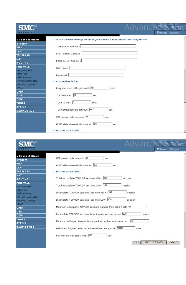
•Connection Policy
Enter the appropriate values for TCP/UDP sessions as described in the
following table.
Parameter Defaults Description
Fragmentation
half-open wait
10 sec Configures the number of seconds that a packet
state structure remains active. When the timeout
value expires, the router drops the unassembled
packet, freeing that structure for use by another
packet.
TCP SYN wait 30 sec Defines how long the software will wait for a
TCP session to synchronize before dropping the
session.
TCP FIN wait 5 sec Specifies how long a TCP session will be
maintained after the firewall detects a FIN
packet.
TCP connection
idle timeout
3600
seconds
(1 hour)
The length of time for which a TCP session will
be managed if there is no activity.
UDP session idle
timeout
30 sec The length of time for which a UDP session will
be managed if there is no activity.
H.323 data channel
idle timeout
180 sec The length of time for which an H.323 session
will be managed if there is no activity.

C
ONFIGURING THE
ADSL R
OUTER
4-52
•DoS Criteria and Port Scan Criteria
Set up DoS and port scan criteria in the spaces provided (as shown below).
Note: The firewall does not significantly affect system performance, so
we advise enabling the prevention features, and leaving them at the
default settings to protect your network.
Parameter Defaults Description
Total incomplete
TCP/UDP sessions
HIGH
300
sessions
Defines the rate of new unestablished sessions
that will cause the software to start deleting
half-open sessions.
Total incomplete
TCP/UDP sessions
LOW
250
sessions
Defines the rate of new unestablished sessions
that will cause the software to stop deleting half-
open sessions.
Incomplete
TCP/UDP sessions
(per min) HIGH
250
sessions
Maximum number of allowed incomplete
TCP/UDP sessions per minute.
Incomplete
TCP/UDP sessions
(per min) LOW
200
sessions
Minimum number of allowed incomplete
TCP/UDP sessions per minute.
Maximum incomplete
TCP/UDP sessions
number from same
host
10 Maximum number of incomplete TCP/UDP
sessions from the same host.
Incomplete
TCP/UDP sessions
detect sensitive time
period
300
msec
Length of time before an incomplete
TCP/UDP session is detected as incomplete.
Maximum half-open
fragmentation packet
number from same
host
30 Maximum number of half-open fragmentation
packets from the same host.
Half-open
fragmentation detect
sensitive time period
10000
msec
Length of time before a half-open
fragmentation session is detected as half-open.
Flooding cracker
block time
300
second
Length of time from detecting a flood attack to
blocking the attack.
A
DVANCED SETUP
4-53
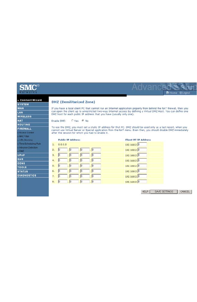
DMZ
If you have a client PC that cannot run an Internet application properly
from behind the firewall, you can open the client up to unrestricted
two-way Internet access. Enter the IP address of a DMZ (Demilitarized
Zone) host on this screen. Adding a client to the DMZ may expose your
local network to a variety of security risks, so only use this option as a last
resort.
C
ONFIGURING THE
ADSL R
OUTER
4-54
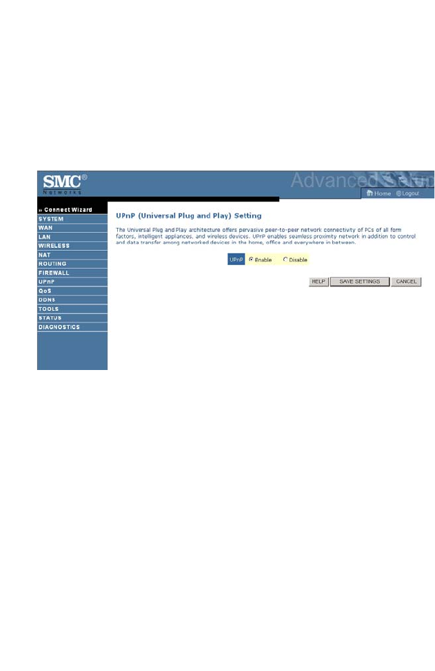
UPnP
The Universal Plug and Play architecture offers pervasive peer-to-peer
network connectivity of PCs of all form factors, intelligent appliances, and
wireless devices. UPnP enables seamless proximity network in addition to
control and data transfer among networked devices in the office, home
and everywhere within your network.
UPnP allows the device to automatically:
• join a network
• obtain an IP address
• convey its capabilities and learn about the presence and capabilities of
other devices.
Check the Enable option to activate the function.
A
DVANCED SETUP
4-55
QoS
The QoS (Quality of Service) function allows you to differentiate traffic
types and provide high-priority forwarding service for applications such as
VoIP or gaming.
Parameter Description
Enable or disable QoS
module function
Check to enable or disable this function.
Diffserv Forwarding Groups
BE Best Effort forwarding, set the percentage for this
type od Qos.
AF1x
AF2x
AF3x
AF4x
Set the percentage for four different types of
Assured Forwarding.
EF Expedited Forwarding, is intended to provide low
delay, low jitter and low loss delivery of packets.
C
ONFIGURING THE
ADSL R
OUTER
4-56
Traffic Mapping
Use this screen to classify traffic into Diffserv forwarding groups and
outgoing VCs.
Click Add traffic class to add a new rule for traffic class.
A
DVANCED SETUP
4-57
Traffic Statistics
This screen shows the WAN outbound traffic statistics of all the Diffserv
forwarding groups in the last 12 hours.
Click Refresh to renew the list.
C
ONFIGURING THE
ADSL R
OUTER
4-58
DDNS
Dynamic Domain Name Service (DDNS) provides users on the Internet
with a method to tie their domain name to a computer or server. DDNS
allows your domain name to follow your IP address automatically by
having your DNS records changed when your IP address changes.
This DDNS feature is powered by:
•DynDNS.org
•TZO.com
With a DDNS connection you can host your own web site, email server,
FTP site, and more at your own location even if you have a dynamic IP
address.
A
DVANCED SETUP
4-59
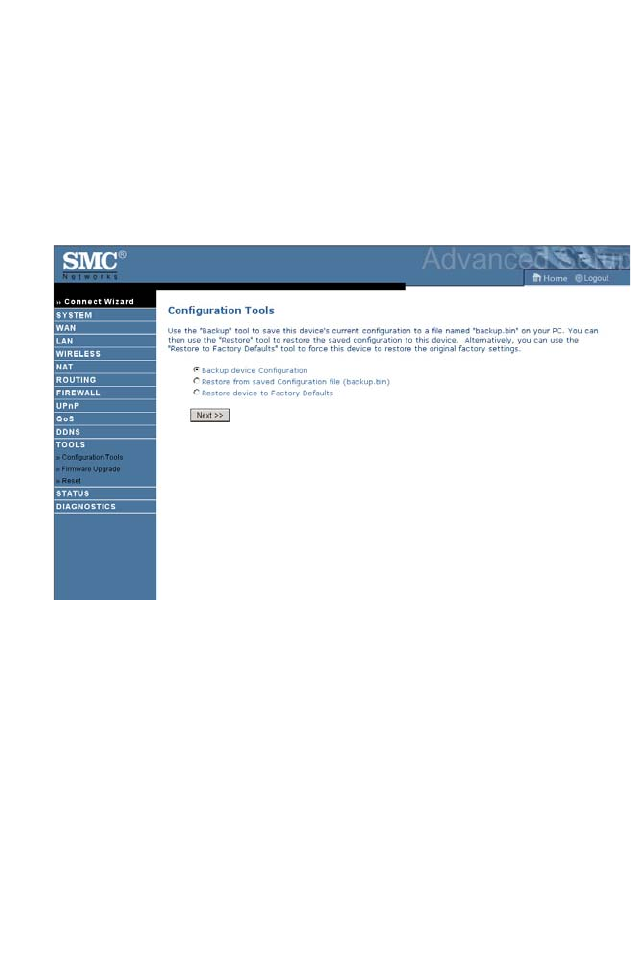
Tools
Use the Tools menu to backup the current configuration, restore a
previously saved configuration, restore factory settings, update firmware,
and reset the ADSL router.
Configuration Tools
• Backup allows you to save the ADSL router’s configuration to a file.
• Restore can be used to restore the previously saved backup
configuration file.
• Restore to Factory Defaults resets the ADSL router back to the
original settings.
Choose a function and click Next.
C
ONFIGURING THE
ADSL R
OUTER
4-60
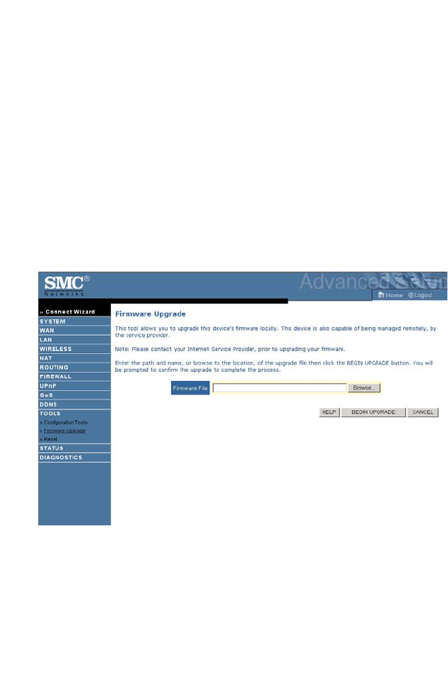
Firmware Upgrade
Use this screen to update the firmware or user interface to the latest
versions.
1. Download the upgrade file from the SMC web site first, and save it to
your hard drive.
2. In the Firmware file field, click “Browse...” to look for the
downloaded file. Click BEGIN UPGRADE.
3. Check the Status screen Information section to confirm that the
upgrade process was successful.
A
DVANCED SETUP
4-61
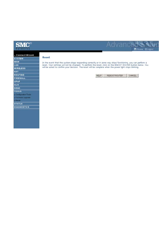
Reset
Click REBOOT ROUTER to reset the ADSL router. The reset will be
complete when the power LED stops blinking.
If you perform a reset from this screen, the configurations will not be
changed back to the factory default settings.
Note: If you use the Reset button on the back panel, the ADSL router
performs a power reset. If the button is pressed for over five
seconds, all the LEDs will illuminate and the factory default
settings will be restored.
C
ONFIGURING THE
ADSL R
OUTER
4-62
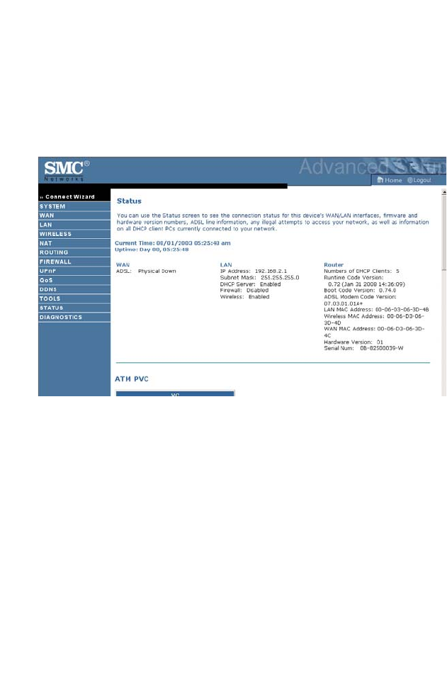
Status
The Status screen displays WAN/LAN connection status, firmware, and
hardware version numbers, illegal attempts to access your network, as well
as information on DHCP clients connected to your network. The security
log may be saved to a file by clicking “Save” and choosing a location.
Scroll down to view more information.
A
DVANCED SETUP
4-63
C
ONFIGURING THE
ADSL R
OUTER
4-64
A
DVANCED SETUP
4-65
Diagnostics
The diagnostics screen provides a quick view for you to troubleshoot the
connection status for LAN ports, WAN port, and Internet access.

C
ONFIGURING THE
ADSL R
OUTER
4-66
Finding the MAC address of a Network
Card
Windows 2000/XP
Click Start/Programs/Command Prompt. Type “ipconfig /all” and press
“ENTER”.
The MAC address is listed as the “Physical Address.”
Macintosh
Click System Preferences/Network.
The MAC address is listed as the “Ethernet Address” on the TCP/IP tab.
Linux
Run the command “/sbin/ifconfig.”
The MAC address is the value after the word “HWaddr.”

A-1
A
PPENDIX
A
T
ROUBLESHOOTING
This section describes common problems you may encounter and possible
solutions to them. The ADSL router can be easily monitored through
panel indicators to identify problems.
Troubleshooting Chart
Symptom Action
LED Indicators
Power LED is
Off
• Check connections between the ADSL router,
the external power supply, and the wall outlet.
• If the power indicator does not turn on when the
power cord is plugged in, you may have a
problem with the power outlet, power cord, or
external power supply. However, if the unit
powers off after running for a while, check for
loose power connections, power losses, or
surges at the power outlet.
If you still cannot isolate the problem, then the
external power supply may be defective. In this
case, contact Technical Support for assistance.

T
ROUBLESHOOTING
A-2
LED Indicators
Link LED is Off • Verify that the ADSL router and attached device
are powered on.
• Be sure the cable is plugged into both the ADSL
router and the corresponding device.
• Verify that the proper cable type is used and that
its length does not exceed the specified limits.
• Be sure that the network interface on the
attached device is configured for the proper
communication speed and duplex mode.
• Check the adapter on the attached device and
cable connections for possible defects. Replace
any defective adapter or cable if necessary.
Network Connection Problems
Cannot ping the
ADSL router
from the
attached LAN
• Verify that the IP addresses are properly
configured. For most applications, you should
use the ADSL router’s DHCP function to
dynamically assign IP addresses to hosts on the
attached LAN. However, if you manually
configure IP addresses on the LAN, verify that
the same network address (network component
of the IP address) and subnet mask are used for
both the ADSL router and any attached LAN
devices.
• Be sure the device you want to ping (or from
which you are pinging) has been configured for
TCP/IP.
Troubleshooting Chart
Symptom Action

T
ROUBLESHOOTING
A-3
Management Problems
Cannot connect
using the web
browser
• Be sure to have configured the ADSL router
with a valid IP address, subnet mask, and default
gateway.
• Check that you have a valid network connection
to the ADSL router and that the port you are
using has not been disabled.
• Check the network cabling between the
management station and the ADSL router.
Forgot or lost
the password
• Press the Reset button on the rear panel (holding
it down for at least five seconds) to restore the
factory defaults.
Troubleshooting Chart
Symptom Action

T
ROUBLESHOOTING
A-4
Wireless Problems
A wireless PC
cannot associate
with the ADSL
router.
• Make sure the wireless PC has the same SSID
settings as the ADSL router. See “Channel and
SSID” on page 4-26.
• You need to have the same security settings on
the clients and the ADSL router. See “Security”
on page 4-28.
The wireless
network is often
interrupted.
• Move your wireless PC closer to the ADSL
router to find a better signal. If the signal is still
weak, change the angle of the antenna.
• There may be interference, possibly caused by a
microwave ovens or wireless phones. Change
the location of the interference sources or of the
ADSL router.
• Change the wireless channel on the ADSL
router. See “Channel and SSID” on page 4-26.
• Check that the antenna, connectors, and cabling
are firmly connected.
The ADSL
router cannot be
detected by a
wireless client.
• The distance between the ADSL router and
wireless PC is too great.
• Make sure the wireless PC has the same SSID
and security settings as the ADSL router. See
ADSL router. See “Channel and SSID” on
page 4-26 and “Security” on page 4-28.
Troubleshooting Chart
Symptom Action

B-1
A
PPENDIX
B
C
ABLES
Ethernet Cable
Caution: DO NOT plug a phone jack connector into any RJ-45 port.
Use only twisted-pair cables with RJ-45 connectors that
conform with FCC standards.
Specifications
Wiring Conventions
For Ethernet connections, a twisted-pair cable must have two pairs of
wires. Each wire pair is identified by two different colors. For example,
one wire might be red and the other, red with white stripes. Also, an RJ-45
connector must be attached to both ends of the cable.
Cable Types and Specifications
Cable Type Max. Length Connector
10BASE-T Cat. 3, 4, 5 100-ohm UTP 100 m (328 ft) RJ-45
100BASE-TX Cat. 5 100-ohm UTP 100 m (328 ft) RJ-45
C
ABLES
B-2
Each wire pair must be attached to the RJ-45 connectors in a specific
orientation. The following figure illustrates how the pins on an Ethernet
RJ-45 connector are numbered. Be sure to hold the connectors in the same
orientation when attaching the wires to the pins.
Figure B-1. RJ-45 Ethernet Connector Pin Numbers
RJ-45 Port Connection
Use the straight-through CAT-5 Ethernet cable provided in the package to
connect the ADSL router to your PC. When connecting to other network
devices such as an Ethernet switch, use the cable type shown in the
following table.
Attached Device Port
Type
Connecting Cable Type
MDI-X Crossover
MDI Straight-through

E
THERNET
C
ABLE
B-3
Pin Assignments
With 100BASE-TX/10BASE-T cable, pins 1 and 2 are used for
transmitting data, and pins 3 and 6 for receiving data.
Straight-Through Wiring
If the port on the attached device has internal crossover wiring (MDI-X),
then use straight-through cable.
RJ-45 Pin Assignments
Pin Number Assignment1
1Tx+
2Tx-
3Rx+
6Rx-
1: The “+” and “-” signs represent the polarity of the wires
that make up each wire pair.
Straight-Through Cable Pin Assignments
End 1 End 2
1 (Tx+) 1 (Tx+)
2 (Tx-) 2 (Tx-)
3 (Rx+) 3 (Rx+)
6 (Rx-) 6 (Rx-)

C
ABLES
B-4
Crossover Wiring
If the port on the attached device has straight-through wiring (MDI), use
crossover cable.
Crossover Cable Pin Assignments
End 1 End 2
1 (Tx+) 3 (Rx+)
2 (Tx-) 6 (Rx-)
3 (Rx+) 1 (Tx+)
6 (Rx-) 2 (Tx-)

C-1
A
PPENDIX
C
S
PECIFICATIONS
Physical Characteristics
Ports
Four 10/100Mbps RJ-45 Ports
One ADSL RJ-11
ADSL Features
Supports DMT line modulation
Supports Annex A Full-Rate ADSL: up to 8 Mbps downstream, up to
1 Mbps upstream (G.992.1 &T1.413, Issue 2)
Supports G.Lite ADSL: up to 1.5 Mbps downstream, up to 512 Kbps
upstream
Supports ADSL2/2+: up to 24Mbps downstream, up to 1Mbps upstream
Dying GASP support
ATM Features
RFC1483 Encapsulation (IP, Bridging and encapsulated routing)
PPP over ATM (LLC &VC multiplexing) (RFC2364)
Classical IP (RFC1577)
Traffic shaping (UBR, CBR)
OAM F4/F5 support
PPP over Ethernet Client
Management Features
Firmware upgrade via WEB Based Management
WEB Based Management (configuration)
Power Indicators
Event and History logging
Network Ping

S
PECIFICATIONS
C-2
Security Features
Password protected configuration access
User authentication (PAP/CHAP) with PPP
Firewall NAT NAPT
VPN pass through
LAN Features
IEEE 802.1D (self-learning transparent Bridging)
DHCP Server
DNS Proxy
Static Routing, RIPv1 and RIP
Applications
Netmeeting, ICQ, Real Player, QuickTime, DialPad, PC Anywhere, Telnet,
SNTP, NNTP
Modulation Type
OFDM, CCK
Operating Channels IEEE 802.11b compliant:
11 channels (US, Canada)
13 channels (ETSI)
14 channels (Japan)
Operating Channels IEEE 802.11g compliant:
11 channels (US, Canada)
13 channels (ETSI)
13 channels (Japan)
Environmental
Temperature: IEC 68-2-14
0 to 40 degrees C (Standard Operating)
-20 to 70 degree C (Non-operation)
Humidity: 10% to 95% (Noncondensing)
Vibration: IEC 68-2-36, IEC 68-2-6
Shock: IEC 68-2-29
Drop: IEC 68-2-32

S
PECIFICATIONS
C-3
Dimensions
159.3 x 133.4 x 32.1 (mm)
Weight
290 g
Input Power
12 V 1 A
IEEE Standards
IEEE 802.3, 802.3u, 802.11g, 802.1D
ITU G.dmt
ITU G.Handshake
ITU T.413 issue 2 - ADSL full rate
Standards Conformance Electromagnetic Compatibility
CE
R&TTE
ETSI
FCC part 15 Class B
FCC part 68
RoHS
Safety
EN 60950-1 & IEC 60950-1
Internet Standards
RFC 826 ARP
RFC 791 IP
RFC 792 ICMP
RFC 768 UDP
RFC 793 TCP
RFC 783 TFTP
RFC 1483 AAL5 Encapsulation
RFC 1661 PPP
RFC 1866 HTML
RFC 2068 HTTP
RFC 2364 PPP over ATM