Arcadyan Technology WA4001AARC SpeedTouch 180 Wireless Access Point User Manual 00
Arcadyan Technology Corporation SpeedTouch 180 Wireless Access Point 00
User Manual

WA4001A-BT
SpeedTouch 180
Wireless Access Point

iii
C
OMPLIANCES
Federal Communication Commission Interference
Statement
This equipment has been tested and found to comply with the limits for a Class B digital
device, pursuant to Part 15 of the FCC Rules. These limits are designed to provide reasonable
protection against harmful interference in a residential installation. This equipment generates,
uses and can radiate radio frequency energy and, if not installed and used in accordance with
the instructions, may cause harmful interference to radio communications. However, there is
no guarantee that interference will not occur in a particular installation. If this equipment
does cause harmful interference to radio or television reception, which can be determined by
turning the equipment off and on, the user is encouraged to try to correct the interference by
one of the following measures:
- Reorient or relocate the receiving antenna
- Increase the separation between the equipment and receiver
- Connect the equipment into an outlet on a circuit different from that to which the receiver
is connected
- Consult the dealer or an experienced radio/TV technician for help
This device complies with Part 15 of the FCC Rules. Operation is subject to the following
two conditions: (1) This device may not cause harmful interference, and (2) this device must
accept any interference received, including interference that may cause undesired operation.
FCC Caution: Any changes or modifications not expressly approved by the party responsible
for compliance could void the user's authority to operate this equipment.
IMPORTANT NOTE
FCC Radiation Exposure Statement:
This equipment complies with FCC radiation exposure limits set forth for an uncontrolled
environment. This equipment should be installed and operated with minimum distance 20cm
between the radiator & your body.
This transmitter must not be co-located or operating in conjunction with any other antenna
or transmitter.
The equipment version marketed in US is restricted to usage of the channels
1- 11 only.

C
OMPLIANCES
iv
EC Conformance Declaration - Class B
This information technology equipment complies with the requirements of the Council
Directive 89/336/EEC on the Approximation of the laws of the Member States relating to
Electromagnetic Compatibility and 73/23/EEC for electrical equipment used within certain
voltage limits and the Amendment Directive 93/68/EEC. For the evaluation of the
compliance with these Directives, the following standards were applied:
RFI
Emission: • Limit class B according to EN 55022:1998
• Limit class B for harmonic current emission according to
EN 61000-3-2/1995
• Limitation of voltage fluctuation and flicker in low-voltage supply
system according to EN 61000-3-3/1995
Immunity: • Product family standard according to EN 55024:1998
• Electrostatic Discharge according to EN 61000-4-2:1995
(Contact Discharge: ±4 kV, Air Discharge: ±8 kV)
• Radio-frequency electromagnetic field according to
EN 61000-4-3:1996 (80 - 1000 MHz with 1 kHz AM 80%
Modulation: 3 V/m)
• Electrical fast transient/burst according to EN 61000-4-4:1995
(AC/DC power supply: ±1 kV, Data/Signal lines: ±0.5 kV)
• Surge immunity test according to EN 61000-4-5:1995
(AC/DC Line to Line: ±1 kV, AC/DC Line to Earth: ±2 kV)
• Immunity to conducted disturbances, Induced by radio-frequency
fields:
EN 61000-4-6:1996 (0.15~80 MHz with 1 kHz AM 80%
Modulation: 3 V/m)
• Power frequency magnetic field immunity test according to
EN 61000-4-8:1993 (1 A/m at frequency 50 Hz)
• Voltage dips, short interruptions and voltage variations immunity
test according to EN 61000-4-11:1994 (>95% Reduction @10
ms, 30% Reduction @500 ms, >95% Reduction @5000 ms)
LVD: • EN 60950 (A1/1992; A2/1993; A3/1993; A4/1995; A11/1997)

C
OMPLIANCES
v
Safety Compliance
Wichtige Sicherheitshinweise (Germany)
1. Bitte lesen Sie diese Hinweise sorgfältig durch.
2. Heben Sie diese Anleitung für den späteren Gebrauch auf.
3. Vor jedem Reinigen ist das Gerät vom Stromnetz zu trennen. Verwenden Sie keine
Flüssigoder Aerosolreiniger. Am besten eignet sich ein angefeuchtetes Tuch zur
Reinigung.
4. Die Netzanschlu ßsteckdose soll nahe dem Gerät angebracht und leicht zugänglich sein.
5. Das Gerät ist vor Feuchtigkeit zu schützen.
6. Bei der Aufstellung des Gerätes ist auf sicheren Stand zu achten. Ein Kippen oder Fallen
könnte Beschädigungen hervorrufen.
7. Die Belüftungsöffnungen dienen der Luftzirkulation, die das Gerät vor Überhitzung
schützt. Sorgen Sie dafür, daß diese Öffnungen nicht abgedeckt werden.
8. Beachten Sie beim Anschluß an das Stromnetz die Anschlußwerte.
9. Verlegen Sie die Netzanschlußleitung so, daß niemand darüber fallen kann. Es sollte auch
nichts auf der Leitung abgestellt werden.
10. Alle Hinweise und Warnungen, die sich am Gerät befinden, sind zu beachten.
11. Wird das Gerät über einen längeren Zeitraum nicht benutzt, sollten Sie es vom Stromnetz
trennen. Somit wird im Falle einer Überspannung eine Beschädigung vermieden.
12. Durch die Lüftungsöffnungen dürfen niemals Gegenstände oder Flüssigkeiten in das
Gerät gelangen. Dies könnte einen Brand bzw. elektrischen Schlag auslösen.
13. Öffnen sie niemals das Gerät. Das Gerät darf aus Gründen der elektrischen Sicherheit
nur von authorisiertem Servicepersonal geöffnet werden.
14. Wenn folgende Situationen auftreten ist das Gerät vom Stromnetz zu trennen und von
einer qualifizierten Servicestelle zu überprüfen:
a. Netzkabel oder Netzstecker sind beschädigt.
b. Flüssigkeit ist in das Gerät eingedrungen.
c. Das Gerät war Feuchtigkeit ausgesetzt.
d. Wenn das Gerät nicht der Bedienungsanleitung entsprechend funktioniert oder Sie mit
Hilfe dieser Anleitung keine Verbesserung erzielen.
e. Das Gerät ist gefallen und/oder das Gehäuse ist beschädigt.
f. Wenn das Gerät deutliche Anzeichen eines Defektes aufweist.
15. Zum Netzanschluß dieses Gerätes ist eine geprüfte Leitung zu verwenden. Für einen
Nennstrom bis 6 A und einem Gerätegewicht größer 3 kg ist eine Leitung nicht leichter
als H05VV-F, 3G, 0.75 mm2 einzusetzen.
Der arbeitsplatzbezogene Schalldruckpegel nach DIN 45 635 Teil 1000 beträgt 70 dB(A) oder
weniger.

C
OMPLIANCES
vi

vii
T
ABLE
OF
C
ONTENTS
1 Introduction . . . . . . . . . . . . . . . . . . . . . . . . . . . . . . . . . .1-1
About the SpeedTouch 180 . . . . . . . . . . . . . . . . . . . . . . . . . . . . . . . . . . . 1-1
Features and Benefits . . . . . . . . . . . . . . . . . . . . . . . . . . . . . . . . . . . . . . . . 1-1
Applications . . . . . . . . . . . . . . . . . . . . . . . . . . . . . . . . . . . . . . . . . . . . . . . 1-2
2 Installation . . . . . . . . . . . . . . . . . . . . . . . . . . . . . . . . . . 2-1
Package Contents . . . . . . . . . . . . . . . . . . . . . . . . . . . . . . . . . . . . . . . . . . . 2-1
System Requirements . . . . . . . . . . . . . . . . . . . . . . . . . . . . . . . . . . . . . . . . 2-2
Hardware Description . . . . . . . . . . . . . . . . . . . . . . . . . . . . . . . . . . . . . . . 2-2
Aerial View . . . . . . . . . . . . . . . . . . . . . . . . . . . . . . . . . . . . . . . . . . 2-3
Rear View . . . . . . . . . . . . . . . . . . . . . . . . . . . . . . . . . . . . . . . . . . . 2-3
LED Indicators . . . . . . . . . . . . . . . . . . . . . . . . . . . . . . . . . . . . . . . 2-5
System Requirements . . . . . . . . . . . . . . . . . . . . . . . . . . . . . . . . . . . . . . . . 2-6
3 Configuring the SpeedTouch 180 . . . . . . . . . . . . . . . . 3-1
Using the Management Interface . . . . . . . . . . . . . . . . . . . . . . . . . . . . . . . 3-2
Status . . . . . . . . . . . . . . . . . . . . . . . . . . . . . . . . . . . . . . . . . . . . . . . . . . . . . 3-2
System . . . . . . . . . . . . . . . . . . . . . . . . . . . . . . . . . . . . . . . . . . . . . . . . . . . . 3-3
Password Settings . . . . . . . . . . . . . . . . . . . . . . . . . . . . . . . . . . . . . 3-3
Operating Mode . . . . . . . . . . . . . . . . . . . . . . . . . . . . . . . . . . . . . . 3-5
Reset . . . . . . . . . . . . . . . . . . . . . . . . . . . . . . . . . . . . . . . . . . . . . . . 3-6
Language Settings . . . . . . . . . . . . . . . . . . . . . . . . . . . . . . . . . . . . . 3-6
LAN . . . . . . . . . . . . . . . . . . . . . . . . . . . . . . . . . . . . . . . . . . . . . . . . . . . . . 3-8
LAN Settings . . . . . . . . . . . . . . . . . . . . . . . . . . . . . . . . . . . . . . . . . 3-8
LAN Settings . . . . . . . . . . . . . . . . . . . . . . . . . . . . . . . . . . . . . . . . . 3-9
Wireless . . . . . . . . . . . . . . . . . . . . . . . . . . . . . . . . . . . . . . . . . . . . . . . . . . 3-10
Basic Setting . . . . . . . . . . . . . . . . . . . . . . . . . . . . . . . . . . . . . . . . 3-10
WEP Configuration . . . . . . . . . . . . . . . . . . . . . . . . . . . . . . . . . . 3-12
WPA Configuration . . . . . . . . . . . . . . . . . . . . . . . . . . . . . . . . . . 3-14
Client List . . . . . . . . . . . . . . . . . . . . . . . . . . . . . . . . . . . . . . . . . . 3-17
Connection Control . . . . . . . . . . . . . . . . . . . . . . . . . . . . . . . . . . 3-18
Basic Setting . . . . . . . . . . . . . . . . . . . . . . . . . . . . . . . . . . . . . . . . 3-19
WEP Configuration . . . . . . . . . . . . . . . . . . . . . . . . . . . . . . . . . . 3-20
Repeater Configuration . . . . . . . . . . . . . . . . . . . . . . . . . . . . . . . . . . . . . 3-21

T
ABLE
OF
C
ONTENTS
viii
Tools . . . . . . . . . . . . . . . . . . . . . . . . . . . . . . . . . . . . . . . . . . . . . . . . . . . . 3-24
Configuration . . . . . . . . . . . . . . . . . . . . . . . . . . . . . . . . . . . . . . . 3-25
Firmware Upgrade . . . . . . . . . . . . . . . . . . . . . . . . . . . . . . . . . . . 3-26
Reboot . . . . . . . . . . . . . . . . . . . . . . . . . . . . . . . . . . . . . . . . . . . . . 3-27
Profile . . . . . . . . . . . . . . . . . . . . . . . . . . . . . . . . . . . . . . . . . . . . . 3-28
Status . . . . . . . . . . . . . . . . . . . . . . . . . . . . . . . . . . . . . . . . . . . . . . 3-29
Client Bridge (Infrastructure) Configuration . . . . . . . . . . . . . . . . . . . . 3-30
Client Bridge (AdHoc) Configuration . . . . . . . . . . . . . . . . . . . . . . . . . . 3-31
Home . . . . . . . . . . . . . . . . . . . . . . . . . . . . . . . . . . . . . . . . . . . . . . . . . . . 3-31
Logout . . . . . . . . . . . . . . . . . . . . . . . . . . . . . . . . . . . . . . . . . . . . . . . . . . . 3-31
A Troubleshooting . . . . . . . . . . . . . . . . . . . . . . . . . . . . . .A-1
B Cables . . . . . . . . . . . . . . . . . . . . . . . . . . . . . . . . . . . . . .B-1
Ethernet Cable . . . . . . . . . . . . . . . . . . . . . . . . . . . . . . . . . . . . . . . . . . . . . B-1
Specifications . . . . . . . . . . . . . . . . . . . . . . . . . . . . . . . . . . . . . . . . B-1
Wiring Conventions . . . . . . . . . . . . . . . . . . . . . . . . . . . . . . . . . . . B-1
RJ-45 Port Connection . . . . . . . . . . . . . . . . . . . . . . . . . . . . . . . . . B-2
Pin Assignments . . . . . . . . . . . . . . . . . . . . . . . . . . . . . . . . . . . . . . B-3
C Specifications . . . . . . . . . . . . . . . . . . . . . . . . . . . . . . . .C-1
Glossary . . . . . . . . . . . . . . . . . . . . . . . . . . . . . . . . . . . . . 1-1

1-1
C
HAPTER
1
I
NTRODUCTION
The SpeedTouch 180 is an IEEE 802.11b/g Wireless LAN Access Point
with switchable repeater mode and Ethernet client mode. It provides
transparent, wireless high-speed data communications between the wired
LAN (and/or within the wireless network) and fixed, portable or mobile
devices equipped with an 802.11b/g wireless adapter employing the same
radio modulation.
About the SpeedTouch 180
The SpeedTouch 180 offers fast, reliable wireless connectivity with
considerable cost savings over wired LANs (which include long-term
maintenance overhead for cabling). New technology provides wireless
security via Wired Equivalent Privacy (WEP) encryption, Wi-Fi Protected
Access (WPA), and MAC address filtering.
Features and Benefits
• Wireless connection using IEEE 802.11b/g technology
• When working in Client Bridge mode, the SpeedTouch 180 allows the
wired Ethernet equipped device work wirelessly at 54Mbps
• DHCP for dynamic IP configuration, and DNS for domain name
mapping
• Easy setup through a web browser on any operating system that
supports TCP/IP
• WDS (Wireless Distribution System) is supported.

I
NTRODUCTION
1-2
Applications
SpeedTouch 180 provides great networking features:
• Remote access to corporate network information
Email, file transfer, and terminal emulation.
• Difficult-to-wire environments
Historical or old buildings, asbestos installations, and open areas where
wiring is difficult to employ.
• Frequently changing environments
Retailers, manufacturers, and banks that frequently rearrange the
workplace or change location.
• Temporary LANs for special projects or peak times
Trade shows, exhibitions and construction sites which need temporary
setup for a short time period. Retailers, airline and shipping companies
that need additional workstations for a peak period. Auditors who
require workgroups at customer sites.
• Access to databases for mobile workers
Doctors, nurses, retailers, or white-collar workers who need access to
databases while being mobile in a hospital, retail store, or an office
campus.
• SOHO users
SOHO (Small Office and Home Office) users who need easy and
quick installation of a small computer network.
• Security
The SpeedTouch 180 supports security features that deny Internet
access to specified PCs, or filter all requests for specific services that
might affect your network security. WEP (Wired Equivalent Privacy),
WPA (Wi-Fi Protected Access), and MAC filtering provide security
over the wireless network.

2-1
C
HAPTER
2
I
NSTALLATION
Before installing the SpeedTouch 180, verify that you have all the items
listed under the Package Contents list. If any of the items are missing or
damaged, contact your local distributor. Also be sure that you have all the
necessary cabling before installing the wireless gateway. After installing the
SpeedTouch 180, refer to “Configuring the SpeedTouch 180” on page 3-1.
Package Contents
After unpacking the SpeedTouch 180 box, check the contents to be sure
you have received the following components:
• SpeedTouch 180
• Power adapter
• Documentation CD
Immediately inform your dealer in the event of any incorrect, missing, or
damaged parts. If possible, please retain the carton and original packing
materials in case there is a need to return the product.

I
NSTALLATION
2-2
System Requirements
Your system must meet the following minimum requirements:
• A PC using a fixed IP address or dynamic IP address assigned via
DHCP, as well as a gateway server address and DNS server address
from your service provider.
• An A/C power outlet (100~240 V, 50~60 Hz) which will supply
power for the device.
• A computer equipped with a 10/100 Mbps Ethernet network interface
card, or a USB-to-Ethernet converter or an IEEE 802.11b/g wireless
network adapter.
• TCP/IP network protocols installed on each PC that will access the
Internet.
• A Java-enabled web browser, such as Microsoft Internet Explorer 5.5
or above installed on one PC at your site for configuring the wireless
gateway.
Hardware Description
The SpeedTouch 180 connects to the Internet or to a remote site using its
RJ-45 WAN port. It can be connected directly to your PC or to a local area
network using the 10/100 Mbps LAN port.
The data transmission speed between wired devices connected to your
local area network can run at up to 100 Mbps. Wireless connections can
run up to 54 Mbps with 11g wireless network.
H
ARDWARE
D
ESCRIPTION
2-3
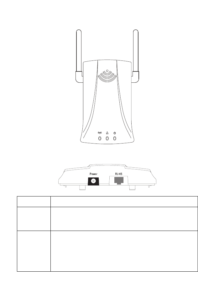
Aerial View
Rear View
Item Description
Power Inlet Connect the included power adapter to this inlet.
Warning: Using the wrong type of power adapter may damage
your adapter.
LAN Port Fast Ethernet port (RJ-45). Connect device (such as a PC, hub or
switch) on your local area network to this port.
This RJ-45 port can auto-negotiate the operating speed to
10/100 Mbps, the mode to half/full duplex, and the pin signals
to MDI/MDI-X (i.e., allowing these ports to be connected to
any network device with straight-through cable).
8mm
8mm
speedtouch

I
NSTALLATION
2-4
Note: If you use the RELOAD button at the bottom of the device, the
SpeedTouch 180 performs a power reset. Unplug the device, and
press the RELOAD button. Power the device again while holding
the RELOAD button down. Releasing the RELOAD button five
seconds after reboot, all the LEDs will illuminate and the factory
settings will be restored.
H
ARDWARE
D
ESCRIPTION
2-5
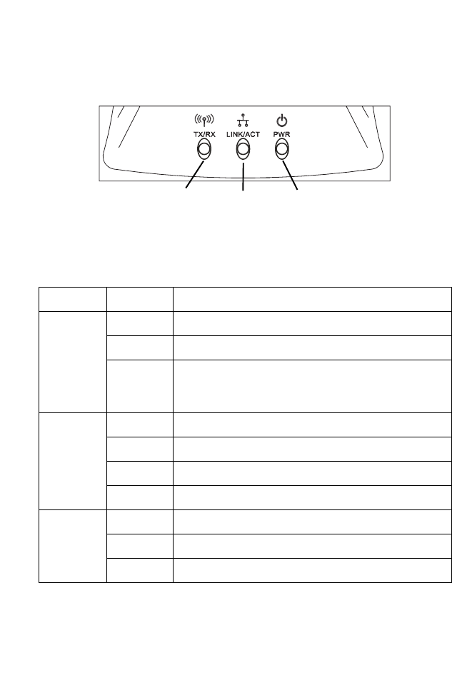
LED Indicators
The LED indicators are illustrated in the following figure and table.
Figure 2-1. LEDs
LED Status Description
WLAN Green Connection has been established.
Blinking The WLAN port is sending or receiving data.
Off Wireless feature has been disabled from the user
interface. The "Enable Wireless Networking" check
box has been de-selected.
LAN Green The connection is established at 100 Mbps.
Yellow The connection is established at 10 Mbps.
Blinking The indicated LAN port is sending or receiving data.
Off There is no traffic on the port.
Power Green The SpeedTouch 180 is receiving power.
Blinking Device is rebooting.
Off Power off or failure.
Power
Ethernet
Link/Activity
Wireless
Link/Activity

I
NSTALLATION
2-6
System Requirements
Before you install the Wireless Access Point, be sure you can meet the
following requirements:
•A/C power outlet (100~240 V, 50~60 Hz) which will supply power
for the access point
•802.11b or 802.11g compliant wireless Ethernet adapters with TCP/IP
compatible protocol installed
• Web browser for configuration
3-1
C
HAPTER
3
C
ONFIGURING
THE
S
PEED
T
OUCH
180
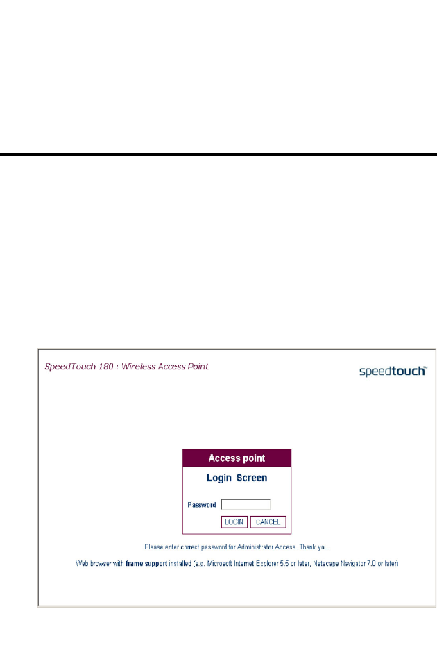
This chapter describes how to configure your SpeedTouch 180. For the
initial connection to the Internet, you firstly need to configure the
SpeedTouch 180. The SpeedTouch 180 can be configured by a web
browser, which is Internet Explorer 5.5 or above.
To access the SpeedTouch 180’s management interface, enter the default
IP address into your web browser: http://10.0.0.140. The default IP
address is a static IP address. Enter the default password (admin), and click
LOGIN to access the management interface.

C
ONFIGURING
THE
S
PEED
T
OUCH
180
3-2
Using the Management Interface
The following items on the menu may be configured: System, LAN,
Wireless, and Tools. To apply configuration changes, click Apply, and if
you want to clear your setting changes, click Cancel. If you wish to view the
previous screen, press Back.
Note: To ensure proper screen refresh after a command entry, be sure
that Internet Explorer 5.5, or above, is configured as follows:
Under the menu Tools/Internet Options/General/Temporary
Internet Files/Settings, the setting for “Check for newer versions
of stored pages” should be “Every visit to the page.”
Status
This is the SpeedTouch 180’s management interface menu homepage.
S
YSTEM
3-3
System
The System menu allows the user choose:
Password Settings
Operating Mode
Language Settings
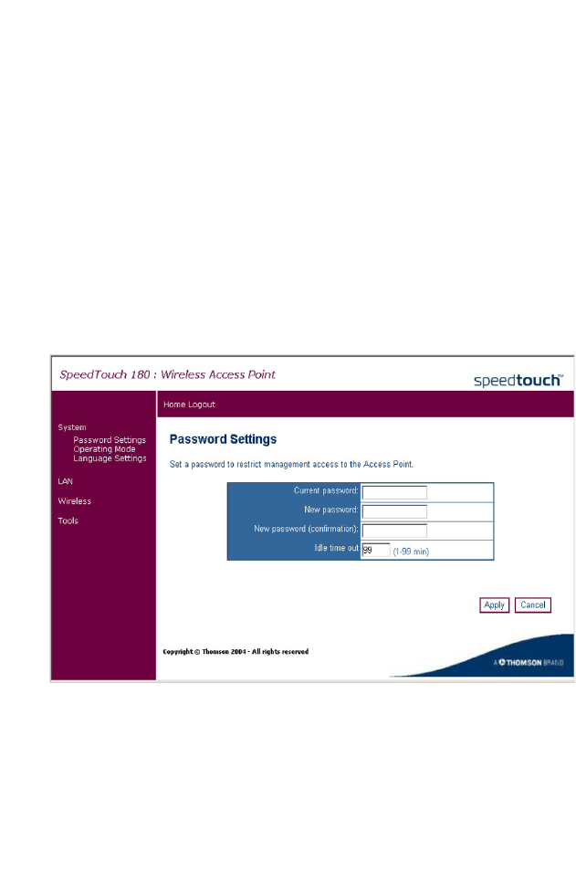
Password Settings
Click System, Password Settings to set the password for administrative
access to the SpeedTouch 180.

C
ONFIGURING
THE
S
PEED
T
OUCH
180
3-4
Please refer to the table below for a description of the password settings.
Note: If your password is lost, or you cannot gain access to the
management interface, unplug the power and then press the
RELOAD button. Restore the factory defaults by holding down
the RELOAD button for at least five seconds while powering up
the device. (The default password is admin.)
Parameter Description
Current
password
Enter the original password. (Default: admin)
New password Enter the new password.
New password
(confirmation)
Confirm the new password.
Idle time
(in minutes)
The maximum period of time (in minutes) for which the
login session is maintained during inactivity. If the
connection is inactive for longer than the maximum idle time,
it will perform a system logout, and you have to log in again
to access the management interface. (Default: 2 minutes)
(Range 1-99 minutes)
S
YSTEM
3-5
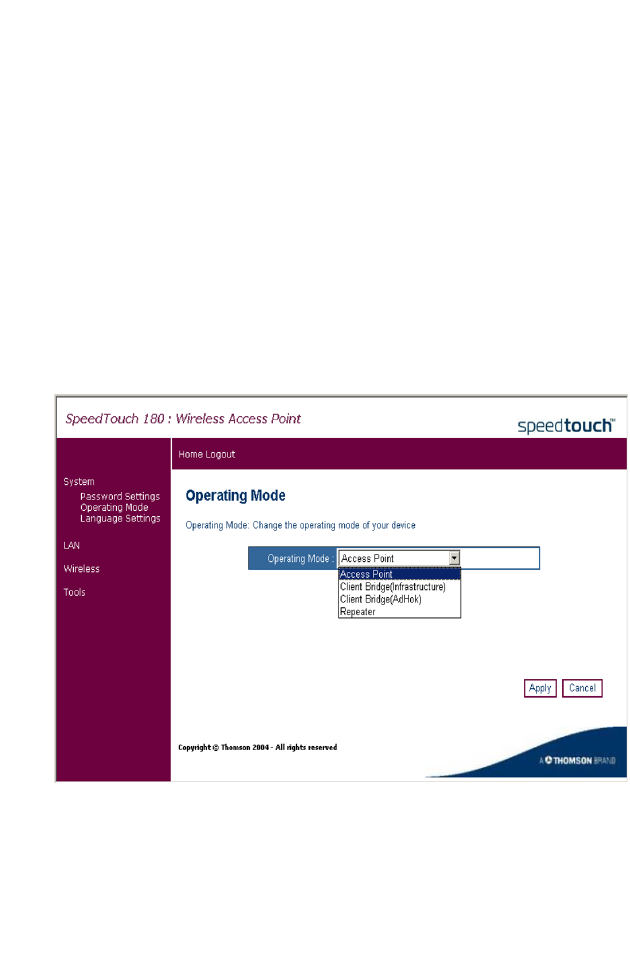
Operating Mode
The SpeedTouch 180 functions in four different modes:
Access Point - provides simple, wireless access to the Internet
Client Bridge (Infrastructure) - enables a wireless infrastructure
connection to a wired ethernet device
Client Bridge (AdHoc) - enables a wireless ad hoc connection to a wired
ethernet device
Repeater - extends the range of your network
Click System, Operating Mode, and choose the desired mode.
Choose the required mode from the drop-down menu. Highlight the
selected mode and click Apply. The device will reboot and ask the user to
log in again. After mode selection, the configuration settings will vary
depending on which mode you are in.

C
ONFIGURING
THE
S
PEED
T
OUCH
180
3-6
Please refer to the table below for a description of these differences.
Reset
If at any time the SpeedTouch 180 becomes unresponsive, it may be
necessary to perform a reset. To perform a system reset, unplug the power
and depress the RELOAD button. Restore the factory defaults by holding
down the RELOAD button for at least five seconds while powering up the
device. (The default password is admin.)
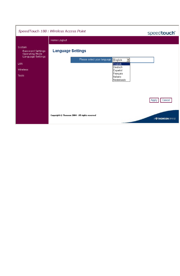
Language Settings
The SpeedTouch 180 offers a choice of the following languages:
English
German
Spanish
French
Italian
Dutch
Mode Description
Access Point
Mode
Contains extra security features. These features - WPA, and
802.1x are described in detail the Wireless, Access Point
Mode section on page 3-10.
Client Bridge
(Infrastructure)
Mode
To enable a wireless connection to your ethernet device,
for example an Xbox, please refer to the configuration page
3-30.
Client Bridge
(AdHoc) Mode
Play head-to-head games using Client Bridge (Ad Hoc)
mode. This process is described on page 3-31.
Repeater Mode In Repeater mode the user must configure the additional
Repeater Settings. Refer to page 3-21.
S
YSTEM
3-7
Click System, Language Settings, and choose the language desired.
Choose the required language from the drop-down menu. Highlight the
selected language and click Apply. The device will change languages
instantly, without rebooting.
C
ONFIGURING
THE
S
PEED
T
OUCH
180
3-8
LAN
You can configure the LAN settings from here.
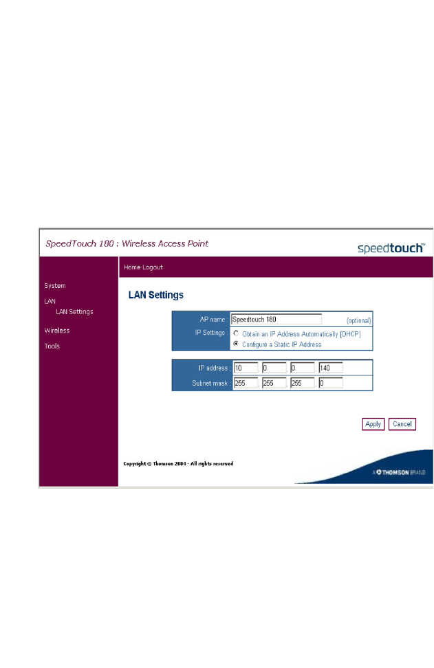
LAN Settings
Access Point Mode
Use the LAN Settings page to configure the LAN IP address. In Access
Point Mode, you may choose to use a static address or to enable the
DHCP server for dynamic client address allocation.
The device will automatically start up with its default static IP address,
10.0.0.140. DNS (Domain Name Servers) map numerical IP addresses to
the equivalent domain name (e.g., www.somesite.com). Your ISP should
provide the IP address of one or more domain name servers.
LAN
3-9
See the table below for a list of the LAN features supported.
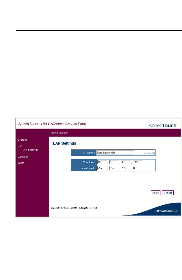
LAN Settings
Client Bridge Mode
Use the LAN Settings page to configure the LAN IP address. In Client
Bridge Mode, you may only use a static address.
The device will automatically start up with its default static IP address,
10.0.0.140. DNS (Domain Name Servers) map numerical IP addresses to
the equivalent domain name (e.g., www.somesite.com). Your ISP should
provide the IP address of one or more domain name servers.
Parameter Description
AP name Name of the access point. (This naming feature is optional.)
IP Settings Selects a dynamic or fixed IP address.
IP address The IP address of the SpeedTouch 180.
Subnet mask The subnet mask of the network.
C
ONFIGURING
THE
S
PEED
T
OUCH
180
3-10
See the table below for a list of the LAN features supported.
Wireless
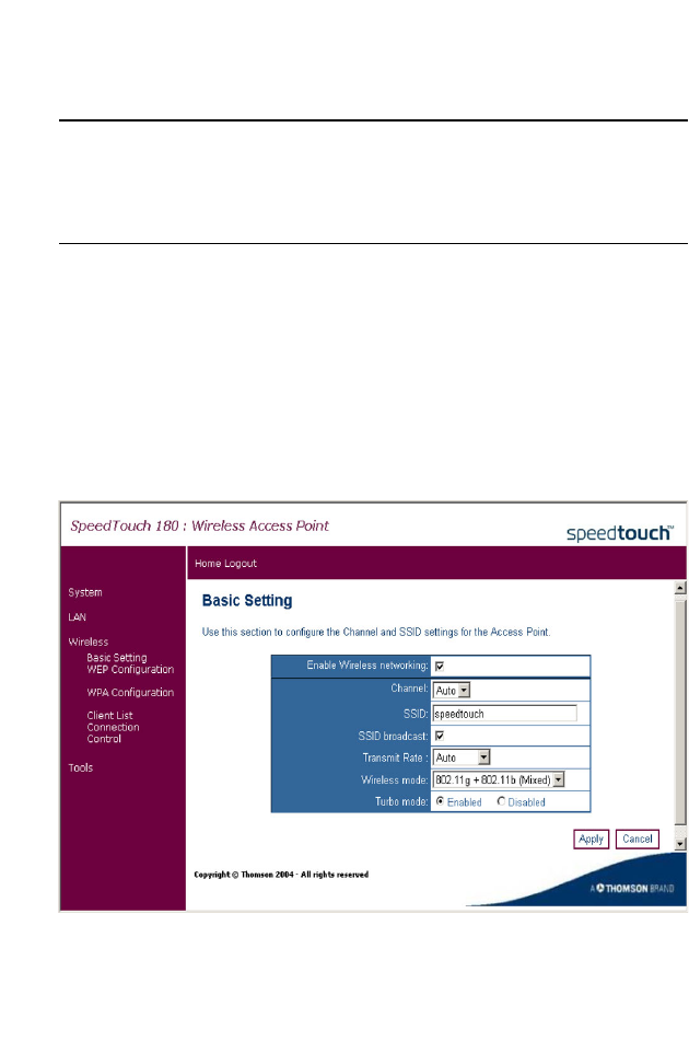
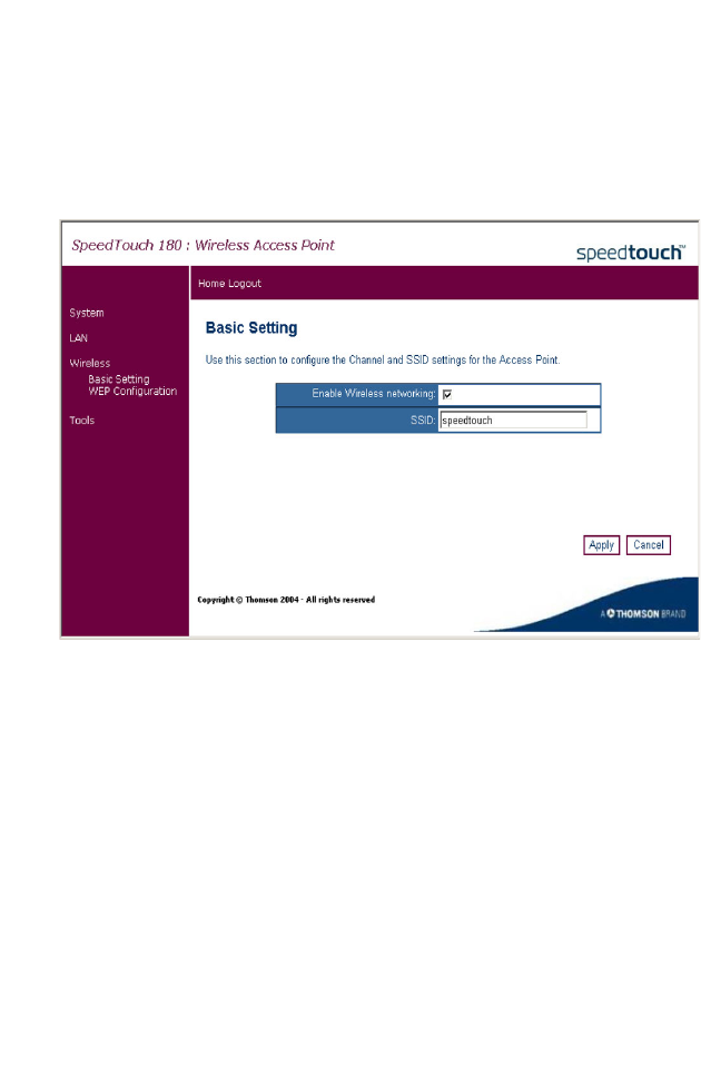
Basic Setting
Access Point Mode
Click on Wireless, Basic Setting to set the channel, Service Set ID (SSID),
and transmit speed for your wireless network.
Parameter Description
AP name Name of the access point. (This naming feature is optional.)
IP address The IP address of the SpeedTouch 180.
Subnet mask The subnet mask of the network.

W
IRELESS
3-11
The SSID should be set to the same value as other wireless devices on your
network. It is case-sensitive and can consist of up to 32 alphanumeric
characters. The access point can be configured for roaming clients by
setting the service set identifier (SSID), wireless channel, and other
advanced options.
The wireless settings are listed in the table below.
Parameter Description
Enable Wireless
Networking
Enables/disables wireless networking.
Channel The radio channel used for the SpeedTouch 180 to
communicate with the wireless clients. The SpeedTouch
180 will automatically assign itself a radio channel, or you
may select one manually.
The available channel settings are limited by local
regulations.
SSID The Service Set ID. This should be set to the same value as
other wireless devices on your network.
The SSID is case sensitive and can consist of up to 32
alphanumeric characters.
SSID broadcast Allows the user to show/hide the SSID. (Default: Enabled)
Transmit Rate The transmit rate is automatically adjusted based on the
receiving data error rate. Usually the connection quality will
vary depending on the distance between the wireless router
and wireless clients. You can also select a lower
transmission rate to maximize the radio communication
range. (Default: Automatic)
Turbo mode Enables/disables turbo mode. The turbo mode
implemented with the Wireless Access Point can
dramatically boost your wireless connectivity with speeds of
up to 108 Mbps.(Default: Enabled)
Wireless mode Select the type of wireless network. The SpeedTouch 180
can support a mixed mode of 11b and 11g, 11g only, and
11g Turbo.
C
ONFIGURING
THE
S
PEED
T
OUCH
180
3-12
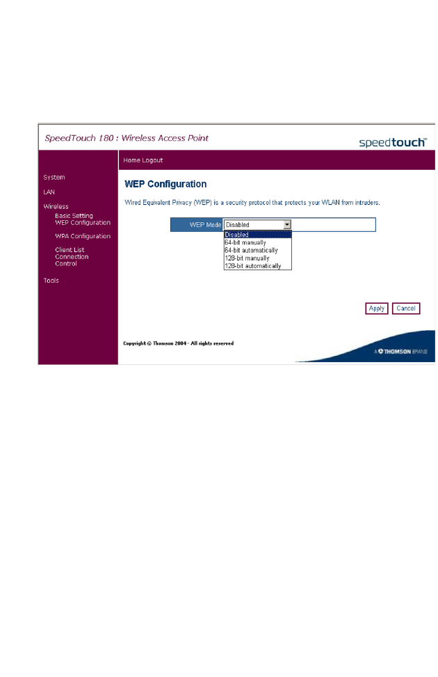
WEP Configuration
Access Point Mode
Click on Wireless, WEP Configuration to configure your WEP parameters.
Wired Equivalent Privacy (WEP) is implemented on this device to prevent
unauthorized access to your wireless network. For network devices that do
not support WPA, it is recommended that you use WEP to protect your
network. If WEP is in use, all clients on the network must use the same
WEP key settings in order to communicate with each other. The device
supports key lengths of the standard 64-bit and industry standard 128-bit.
The bit key can be in alphanumeric characters or hexadecimal numerals
(0~9, A~F, e.g., D7 0A 9C 7F E5). (Default: Disabled)
W
IRELESS
3-13
•WEP Mode
Select the level of WEP encryption you wish to use, 64-bit 10 hex digits or
128-bit 26 hex digits, manual or automatic. Higher encryption levels offer
higher levels of security, but due to the complexity of the encryption, they
may decrease network performance.
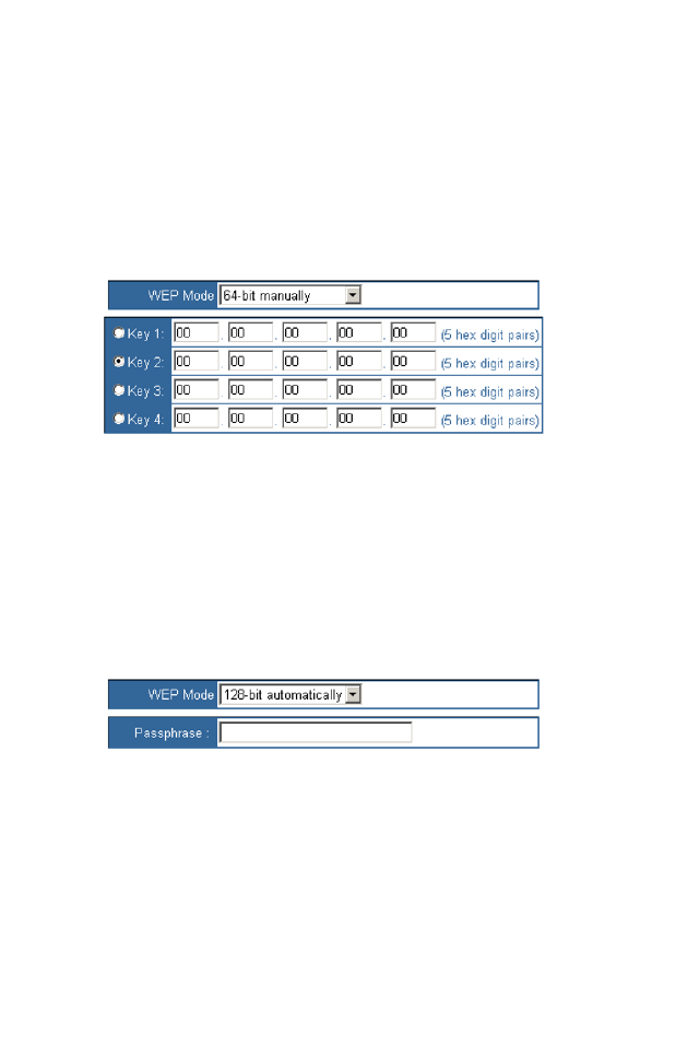
• 64-bit/128-bit manually
If you are not using a Passphrase, then manually enter a set of values.Using
this mode, the user must manually enter keys as 10 hexadecimal digits (0 to
9 and A to F) for 64 bit keys, or 26 hexadecimal digits for 128 bit keys. If
you are using 64-bit WEP encryption, then the key must be exactly 10
hexadecimal characters in length. If you are using 128-bit WEP encryption,
then the key must be exactly 26 hexadecimal characters in length.
• 64-bit/128-bit automatically
Instead of manually entering WEP keys, you can enter a Passphrase. This
Passphrase is used to generate one or more WEP keys.
Note:
All devices in your network must use the same Passphrase or WEP
key.
C
ONFIGURING
THE
S
PEED
T
OUCH
180
3-14
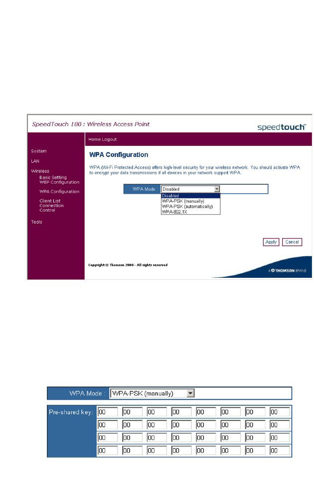
WPA Configuration
Access Point Mode only
Click on Wireless, WPA Configuration to configure your WPA settings.
WPA is a stronger wireless security solution than WEP. It uses a
combination of 802.1x authentication and broadcast/session keys.
• Pre-Shared Key/Passphrase
If there is no authentication server on your SOHO network, you can issue
the Pre-Shared Key to the clients that connect to the Wireless Access
Point. Be sure to use the same key for the Wireless Access Point and the
connected clients.
• WPA-PSK (manually)

W
IRELESS
3-15
• WPA-PSK (automatically)
Notes: 1. Manual Pre-Shared Key supports up to 64-Hex characters.
2. Type 8~63 Hex characters for the Pre-Shared Passphrase.
3. Do not use a key that is too long and complex for your clients to type
accurately.
4. A Hex (hexadecimal) digit is a number or letter in the
range 0-9 or A-F.
For enterprise deployment, WPA requires a RADIUS authentication server
to be configured on the wired network. The 802.1x client and RADIUS
server should use an appropriate EAP type - such as EAP-TLS (Transport
Layer Security), EAP-TTLS (Tunneled TLS), or PEAP (Protected EAP) -
for strongest authentication. Working together, these protocols provide
"mutual authentication" between a client, the access point, and a RADIUS
server that prevents users from accidentally joining a rogue network. Only
when a RADIUS server has authenticated a user’s credentials will
encryption keys be sent to the access point and client.
Note: To implement WPA on wireless clients requires a WPA-enabled
network card driver and 802.1x client software that supports
theEAP authentication type that you want to use. Windows XP
provides native WPA support, other systems require additional
software.
C
ONFIGURING
THE
S
PEED
T
OUCH
180
3-16
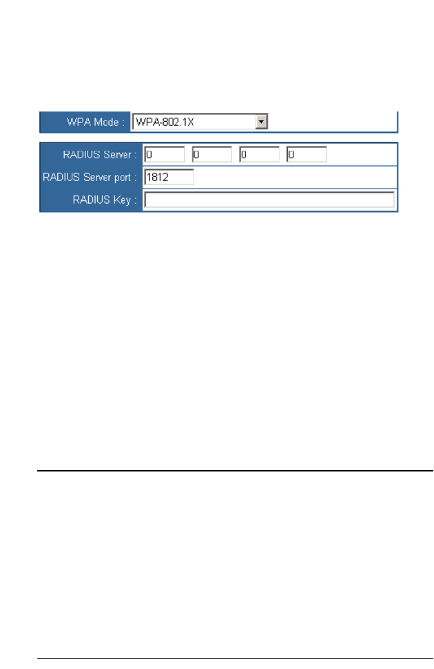
• WPA-802.1X
The Wireless Access Point allows you to use 802.1x authentication for an
enterprise network environment with a RADIUS server installed.
RADIUS is a logon authentication protocol that uses software running on
a central server to control access to RADIUS-compliant devices on the
network. It allows a wireless access point to send the connection
parameters to a RADIUS server. There are two parts to the logon process:
getting user credentials and authentication. Credentials are composed of a
user name, a password, and sometimes a domain. Authentication is the
process of verifying that the users really are who they say they are, based
on the password.
In 802.1x mode, access will be checked against the authentication database
stored on the Wireless Access Point. You must specify the authentication
period, and the corresponding parameters in the RADIUS Server
Parameters field for the remote authentication protocol.
Parameter Default Description
RADIUS
Server
0.0.0.0 The IP address of the RADIUS server.
RADIUS
Server Port
1812 UDP port is used for RADIUS authentication
messages.
RADIUS Key None Defines a text string on both the RADIUS client
and server to secure RADIUS traffic. The
RADIUS server requires MD5 Message-
Authenticator attribute for all access request
messages. The 802.1x authentication scheme is
supported by using the Extensible Authentication
Protocol (EAP) over the RADIUS server.
W
IRELESS
3-17
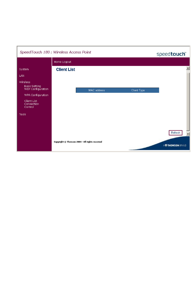
Client List
The Client List screen displays the MAC address and connection speed of
the associated clients.
Click the Refresh button to update the list of clients.
C
ONFIGURING
THE
S
PEED
T
OUCH
180
3-18
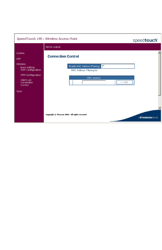
Connection Control
This section provides MAC filtering configuration information.
To use MAC address filtering, you must enter a list of allowed client MAC
addresses into the filtering table. When enabled only the MAC addresses
entered will have access to your network. All other devices will be denied
access to your network.
W
IRELESS
3-19
Basic Setting
Client Bridge Mode
Click on Wireless, Basic Setting to set the Service Set ID (SSID) for your
wireless network.
The SSID should be set to the same value as the wireless network that you
wish to connect to. It is case-sensitive and can consist of up to 32
alphanumeric characters.
In Client Bridge ad hoc mode, the SSID of both devices needs to be
consistent.
C
ONFIGURING
THE
S
PEED
T
OUCH
180
3-20
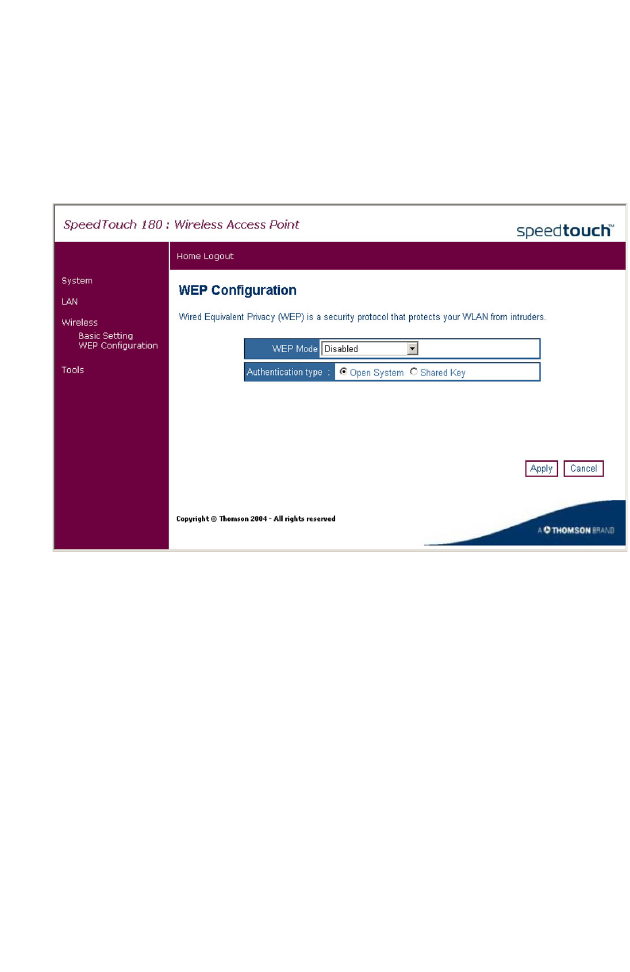
WEP Configuration
Client Bridge Mode
Click on Wireless, WEP Configuration to set the WEP Mode and
Authentication Type.
Wired Equivalent Privacy (WEP) is implemented on this device to prevent
unauthorized access to your wireless network. For network devices that do
not support WPA, it is recommended that you use WEP to protect your
network. If WEP is in use, all clients on the network must use the same
WEP key settings in order to communicate with each other. The device
supports key lengths of the standard 64-bit and industry standard 128-bit.
The bit key can be in alphanumeric characters or hexadecimal numerals
(0~9, A~F, e.g., D7 0A 9C 7F E5).
The user must also choose the authentication type. Open System
essentially means no security. Using the Shared Key setting, users on both
ends of the wireless link have a secret shared key.
R
EPEATER
C
ONFIGURATION
3-21
Repeater Configuration
Repeater Mode
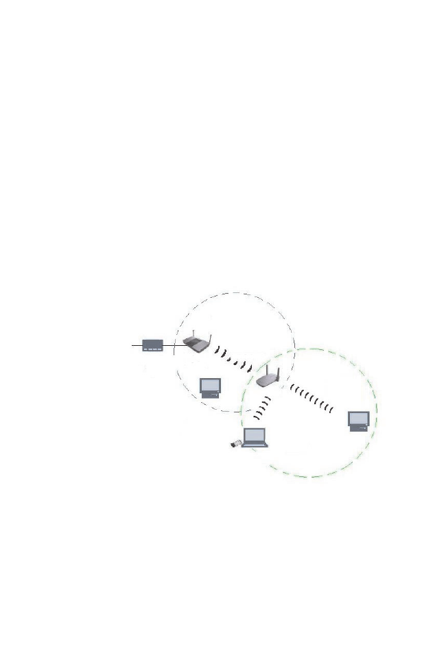
Using the device as a Repeater, you can extend the range of your network.
In Repeater mode, the SpeedTouch 180 uses Wireless Distribution System
(WDS) to extend the coverage of your wireless network. The following
illustration depicts two WDS-enabled devices communicating via WDS.
The user must check the box corresponding to the source device (the 11g
WDS-enabled device in the sketch) in the configuration table of the
repeater (the SpeedTouch 180 in the sketch), in order for the two devices
to communicate.
This page configures the Repeater Settings. Use the Repeater mode to
serve client devices that do not require high throughput. Repeaters extend
the coverage area of your wireless LAN, but they drastically reduce
throughput.
C
ONFIGURING
THE
S
PEED
T
OUCH
180
3-22
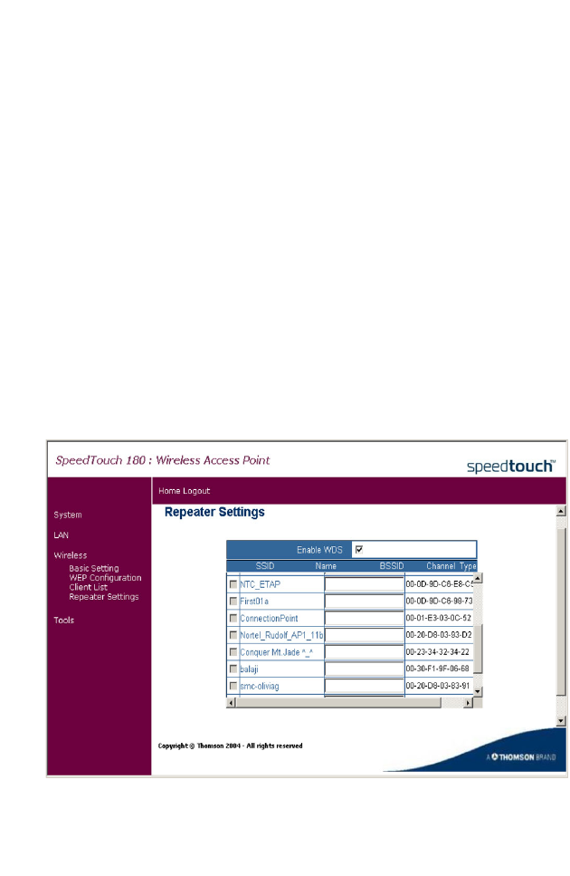
In Repeater mode, the SpeedTouch 180 sends out a signal to check for
other devices on the network. Check the box to enable WDS. Click
Refresh to display all available devices. The above table allows you to
configure the Repeater to repeat the signal of another device. Check the
box corresponding to the device that you want to connect to. Enter a name
that is easy to remember if required, and click Apply. The SpeedTouch 180
can support up to a maximum of four devices in this mode. The user will
receive an error message if this number is exceeded.
Note:
Ensure that both the source and repeating devices are using the same
channel. The check box becomes available only when the channel of
the SpeedTouch 180 and the source is the same. To change the
channel, go to the Basic Setting screen in the Wireless section.
11g WDS-enabled Device (Source)
WDS Link
SpeedTouch 180 (Repeater)
ADSL Modem
R
EPEATER
C
ONFIGURATION
3-23
Note:
Both the source device and the repeating device must be configured
properly to make use of the Repeater mode.
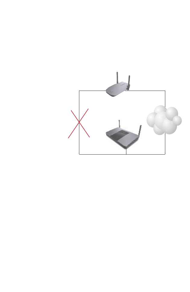
Note: You cannot have a loop in the configuration. A loop will cause a
broadcast storm which will result in high activity on the network
and then all devices will shut down. Please refer to the following
sketch.
Wireless
Network
In a situation like this,
a broadcast storm will
occur
11g WDS-enabled Device
SpeedTouch 180
C
ONFIGURING
THE
S
PEED
T
OUCH
180
3-24
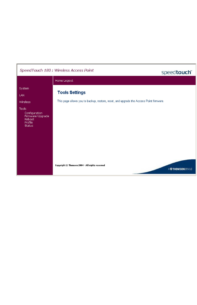
Tools
Use the Tools menu to back up the current configuration, update the
firmware, reboot the SpeedTouch 180, import a profile, or view the
configuration status of the devide.
T
OOLS
3-25
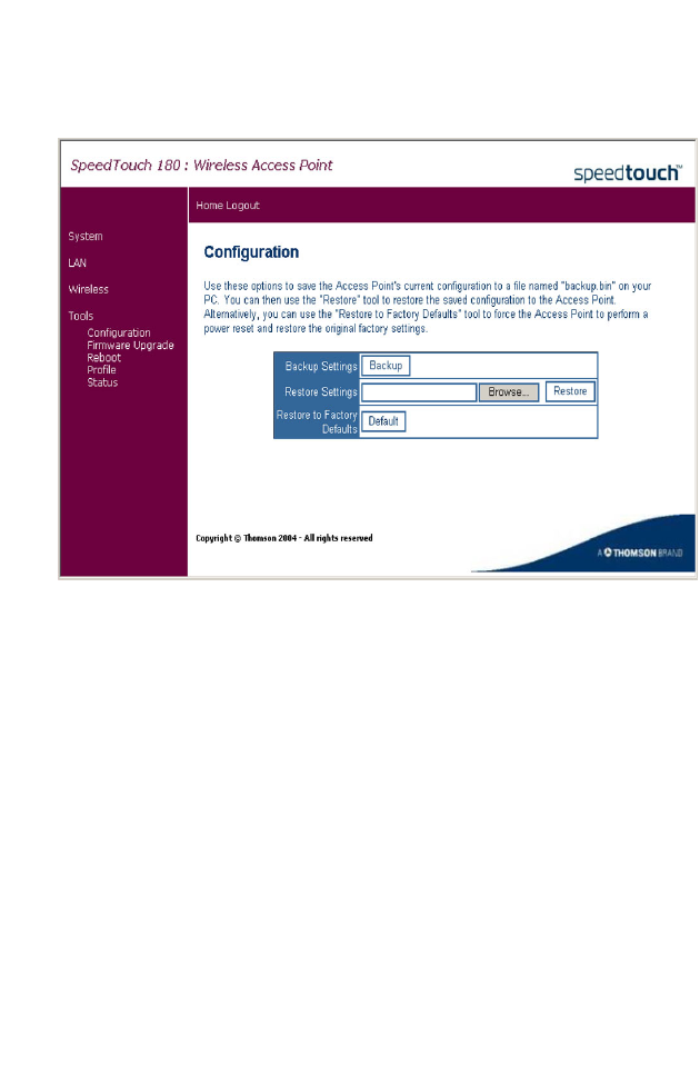
Configuration
Use the Configuration screen to save the current configuration parameters.
• Backup Settings - Saves the SpeedTouch 180 ’s configuration to a file.
• Restore Settings - Restores settings from a previously saved backup
configuration file.
• Restore to Factory Defaults - Restores the SpeedTouch 180 settings
back to the original factory defaults.
C
ONFIGURING
THE
S
PEED
T
OUCH
180
3-26
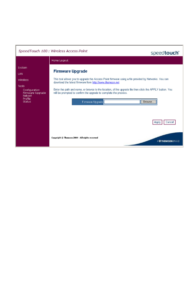
Firmware Upgrade
The Firmware Upgrade page allows the user to upgrade the firmware
using the web management tools.
Firstly, save the new code locally on your hard drive. Then, on the
Firmware Upgrade page, click Browse... to locate the firmware. After
locating the code, click OK to begin the download. The SpeedTouch 180
will automatically reboot after the firmware has been downloaded, and the
user will be asked to log in again. The firmware version displays on the
Status page, for example, 1.00.00.
T
OOLS
3-27
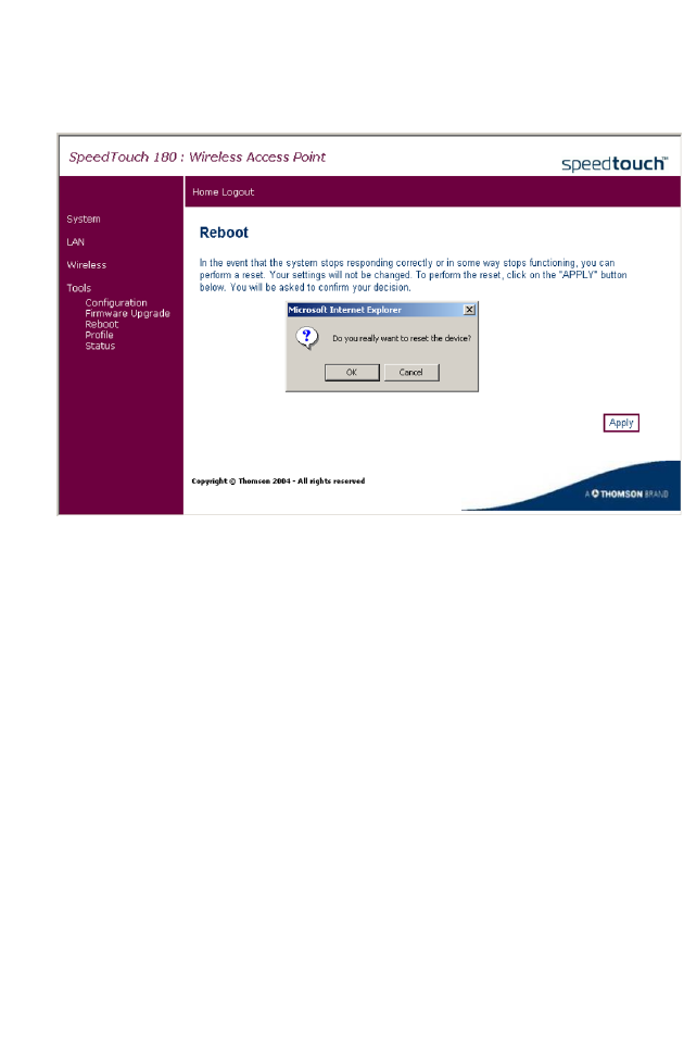
Reboot
The Reboot screen allows the user to reset the device.
Click Apply and then OK on the two confirmation messages to reboot the
SpeedTouch 180. Your settings will not be changed. The reboot will be
complete after 30 seconds.
C
ONFIGURING
THE
S
PEED
T
OUCH
180
3-28
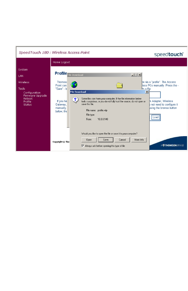
Profile
On the Profile page, you can import the standard Thomson configuration
settings, or profile.
Using this profile, you will not have to configure your wireless PCs
manually. Click Save to save the profile to your hard disk, and Load to load
the profile.
T
OOLS
3-29
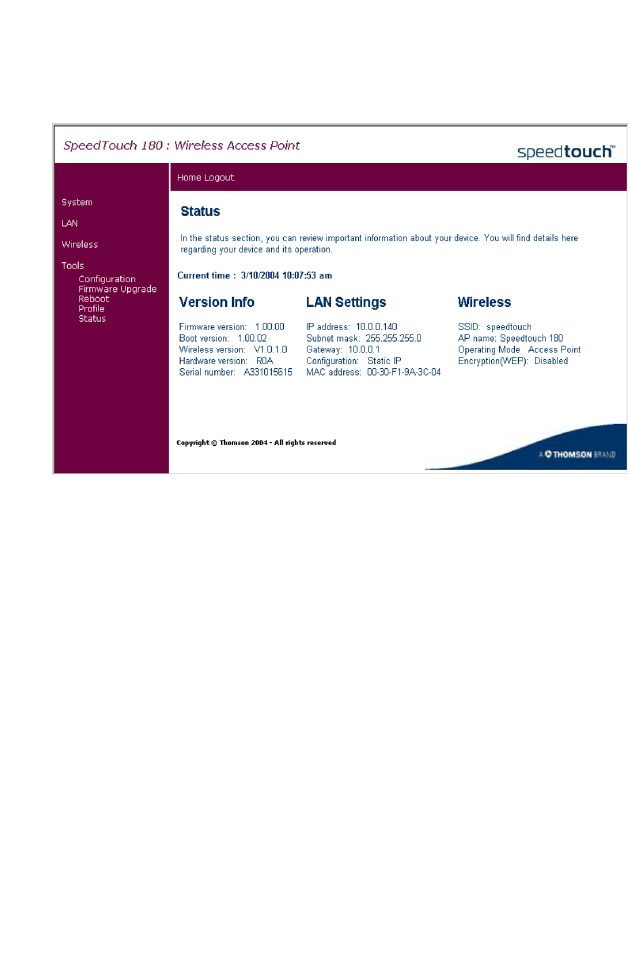
Status
Click Status on the Tools menu to access the Status page.
The Status screen displays the hardware and firmware version numbers,
LAN connection status, and wireless settings of the SpeedTouch 180.

C
ONFIGURING
THE
S
PEED
T
OUCH
180
3-30
Client Bridge (Infrastructure) Configuration
Click on System, Operating Mode, and select Client Bridge
(Infrastructure). Click Apply, and the device will reboot and ask the user to
log in again. Unplug the RJ-45 cable and connect the SpeedTouch 180 to
your ethernet device for example PC, or gaming console, making your
SpeedTouch 180 function as a wireless adapter. The default IP address of
the SpeedTouch 180 is 10.0.0.140. Assign your ethernet device an IP
address statically within the same subnet, for example, 10.0.0.100, so that
you can open the browser and reach the configuration page by typing the
default IP address 10.0.0.140.
Note: Only one ethernet device may be connected to
the SpeedTouch 180.
Ensure that both the SpeedTouch 180 and the 11g WDS-enabled gateway
are using the same SSID.
If you want to use the SpeedTouch 180 as a wireless adapter connected to
your PC, you must remember to release the IP, and set TCP/IP settings to
"Obtain an IP address automatically" after you finish configuring the
SpeedTouch 180. The SpeedTouch 180 will then obtain the IP from the
gateway for your ethernet device (for example, your Xbox), using DHCP.

C
LIENT
B
RIDGE
(A
D
H
OC
) C
ONFIGURATION
3-31
Client Bridge (AdHoc) Configuration
Click on System, Operating Mode, and select Client Bridge (AdHoc) from
the drop-down menu. Click Apply, and the device will reboot and ask the
user to log in again. The SSID on both devices must be the same in order
for the two devices to communicate.
Note: Only one ethernet device may be connected to
the SpeedTouch 180.
Home
Click on Home to return to the homepage.
Logout
Click on Logout to exit the web management interface.

C
ONFIGURING
THE
S
PEED
T
OUCH
180
3-32

A-1
A
PPENDIX
A
T
ROUBLESHOOTING
This section describes common problems you may encounter and possible
solutions to them. The SpeedTouch 180 can be easily monitored through
panel indicators to identify problems.
Troubleshooting Chart
Problem Action
LED Indicators
Power LED is
Off
• Check connections between the SpeedTouch 180, the
external power supply, and the wall outlet.
• If the power indicator does not light when the power
cord is plugged in, you may have a problem with the
power outlet, power cord, or external power supply.
However, if the unit powers off after running for a
while, check for loose power connections, power
losses, or surges at the power outlet.
If you still cannot isolate the problem, then the
external power supply may be defective. In this case,
contact Technical Support for assistance.

T
ROUBLESHOOTING
A-2
LED Indicators
LAN LED is
Off
• Verify that the SpeedTouch 180 and attached device
are powered on.
• Be sure the cable is plugged into both the SpeedTouch
180 and the corresponding device.
• Verify that the proper cable type is used and that its
length does not exceed the specified limits.
• Be sure that the network interface on the attached
device is configured for the proper communication
speed and duplex mode.
• Check the adapter on the attached device and cable
connections for possible defects. Replace any
defective adapter or cable if necessary.
Network Connection Problems
Cannot ping the
SpeedTouch 180
from the
attached LAN
• Verify that the IP addresses are properly configured.
For most applications, you should use the
SpeedTouch 180’s DHCP function to dynamically
assign IP addresses to hosts on the attached LAN.
However, if you manually configure IP addresses on
the LAN, verify that the same network address
(network component of the IP address) and subnet
mask are used for both the SpeedTouch 180 and any
attached LAN devices.
• Be sure the device you want to ping (or from which
you are pinging) has been configured for TCP/IP.
Troubleshooting Chart
Problem Action

T
ROUBLESHOOTING
A-3
Management Problems
Cannot connect
using the web
browser
• Be sure that you have configured the SpeedTouch 180
with a valid IP address, subnet mask, and default
gateway.
• Check that you have a valid network connection to the
SpeedTouch 180 and that the port you are using has
not been disabled.
• Check the network cabling between the management
station and the SpeedTouch 180.
Forgot or lost
the password
• If your password is lost, or you cannot gain access to
the management interface, unplug the power and then
press the reset button. Restore the factory defaults by
holding down the reset button for at least five seconds
while powering up the device. (The default password
is admin.)
Troubleshooting Chart
Problem Action

T
ROUBLESHOOTING
A-4
Wireless Problems
A wireless PC
cannot associate
with the device.
• Make sure the wireless clients use the same SSID
settings as the SpeedTouch 180.
• You need to have the same security settings on the
clients and the SpeedTouch 180.
The wireless
network is often
interrupted.
• Move your wireless clients closer to the SpeedTouch
180 to find a better signal. If the signal is still weak,
change the angle of the antenna.
• There may be interference, possibly caused by
microwave ovens or cordless phones. Change the
location of the interference sources or of the
SpeedTouch 180.
• Change the wireless channel on the 11g WDS-enabled
device.
• Check that the antenna, connectors, and cabling are
firmly connected.
The
SpeedTouch 180
cannot be
detected by a
wireless client.
• The distance between the SpeedTouch 180 and
wireless clients is too far.
• Make sure the wireless clients use the same SSID,
channel, and security settings as the SpeedTouch
180.
In Repeater
mode, a loop has
been detected.
• A broadcast storm has resulted from incorrect set up.
Please refer to page 3-23.
Troubleshooting Chart
Problem Action

B-1
A
PPENDIX
B
C
ABLES
Ethernet Cable
Caution: Do not plug a phone jack connector into any RJ-45 port. Use
only twisted-pair cables with RJ-45 connectors that conform
with FCC standards.
Specifications
Wiring Conventions
For Ethernet connections, a twisted-pair cable must have two pairs of
wires. Each wire pair is identified by two different colors. For example,
one wire might be red and the other, red with white stripes. Also, an RJ-45
connector must be attached to both ends of the cable.
Cable Types and Specifications
Cable Type Max. Length Connector
10BASE-T Cat. 3, 4, 5 100-ohm UTP 100 m (328 ft) RJ-45
100BASE-TX Cat. 5 100-ohm UTP 100 m (328 ft) RJ-45
C
ABLES
B-2
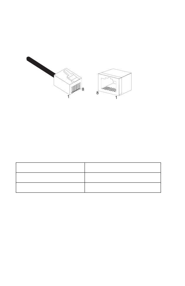
Each wire pair must be attached to the RJ-45 connectors in a specific
orientation. The following figure illustrates how the pins on an Ethernet
RJ-45 connector are numbered. Be sure to hold the connectors in the same
orientation when attaching the wires to the pins.
Figure B-1. RJ-45 Ethernet Connector Pin Numbers
RJ-45 Port Connection
Use the straight-through CAT-5 Ethernet cable provided in the package to
connect the Barricade to your PC. When connecting to other network
devices such as an Ethernet switch, use the cable type shown in the
following table.
Attached Device Port Type Connecting Cable Type
MDI-X Straight-through
MDI Crossover

E
THERNET
C
ABLE
B-3
Pin Assignments
With 100BASE-TX/10BASE-T cable, pins 1 and 2 are used for
transmitting data, and pins 3 and 6 for receiving data.
Straight-Through Wiring
If the port on the attached device has internal crossover wiring (MDI-X),
then use straight-through cable.
RJ-45 Pin Assignments
Pin Number Assignment1
1Tx+
2Tx-
3Rx+
6Rx-
1: The “+” and “-” signs represent the polarity of the wires
that make up each wire pair.
Straight-Through Cable Pin Assignments
End 1 End 2
1 (Tx+) 1 (Tx+)
2 (Tx-) 2 (Tx-)
3 (Rx+) 3 (Rx+)
6 (Rx-) 6 (Rx-)

C
ABLES
B-4
Crossover Wiring
If the port on the attached device has straight-through wiring (MDI), use
crossover cable.
Crossover Cable Pin Assignments
End 1 End 2
1 (Tx+) 3 (Rx+)
2 (Tx-) 6 (Rx-)
3 (Rx+) 1 (Tx+)
6 (Rx-) 2 (Tx-)

C-1
A
PPENDIX
C
S
PECIFICATIONS
General Specifications
Maximum Channels
IEEE 802.11 compliant
11 channels (US, Canada)
13 channels (ETSI)
14 channels (Japan)
LAN Interface
1 RJ-45 10 BASE-T/100 BASE-TX port
Auto-negotiates the connection speed to 10 Mbps Ethernet or 100 Mbps
Fast Ethernet, and the transmission mode to half duplex or full duplex.
Indicator Panel
PWR (Power), LAN (Ethernet Link/Activity), WLAN (Wireless Link/
Activity)
Network Management
HTML Web-browser interface, Windows 98/Me/NT/2000/XP utility
Operating Systems
Windows 98/Me/NT/2000/XP
Dimensions
136 x 89 x 16 (mm)
Weight
150 g
Current Consumption
5V, 1 A maximum

S
PECIFICATIONS
C-2
AC Input
220V ~ 240 AC
DC Output
5V DC
Output Current
2.4 A maximum
Management
Web management
Advanced Features
Dynamic IP Address Configuration – DHCP
Internet Standards
RFC 826 ARP, RFC 791 IP, RFC 792 ICMP, RFC 768 UDP, RFC 793 TCP,
RFC 1483 AAL5 Encapsulation, RFC 1661 PPP, RFC 1866 HTML,
RFC 2068 HTTP, RFC 2364 PPP over ATM
Temperatur e
Operating 0 to 55 °C (32 to 131 °F)
Storage -20 to 70 °C (-4 to 158 °F)
Humidity
5% to 90% (non-condensing)

Glossary-1
G
LOSSARY
10BASE-T
IEEE 802.3 specification for 10 Mbps Ethernet over two pairs of
Category 3, 4, or 5 UTP cable.
100BASE-TX
IEEE 802.3u specification for 100 Mbps Fast Ethernet over two pairs of
Category 5 UTP cable.
Access Point (AP)
An interface between the wireless network and a wired network. Access
points combined with a distribution system (e.g. Ethernet) support the
creation of multiple radio cells (BSSs) that enable roaming throughout a
facility.
Ad Hoc
An ad hoc wireless LAN is a group of computers, each with LAN adapters,
connected as an independent wireless LAN.
Authentication
The process a station uses to announce its identify to another station.
IEEE 802.11 specifies two forms of authentication: open system and
shared key.
Backbone
The core infrastructure of a network. The portion of the network that
transports information from one central location to another central
location where it is unloaded onto a local system.

G
LOSSARY
Glossary-2
Bandwidth
The difference between the highest and lowest frequencies available for
network signals. Also synonymous with wire speed, the actual speed of the
data transmission along the cable.
Base Station
In mobile telecommunications, a base station is the central radio
transmitter/receiver that maintains communications with the mobile
radiotelephone sets within its range. In cellular and personal
communications applications, each cell or micro-cell has its own base
station; each base station in turn is interconnected with other cells’ bases.
Basic Service Set (BSS)
A set of 802.11-compliant stations that operate as a fully-connected
wireless network.
Domain Naming System (DNS)
System used in the Internet for translating names of network nodes into
addresses.
Dynamic Host Configuration Protocol (DHCP)
Issues IP addresses automatically within a specified range to devices such
as PCs when they are first powered on. The device retains the use of the IP
address for a specific license period that the system administrator can
define. DHCP is available as part of the many operating systems including
Microsoft Windows NT Server and UNIX.
Ethernet
A network communication system developed and standardized by DEC,
Intel, and Xerox, using baseband transmission, CSMA/CD access, logical
bus topology, and coaxial cable. The successor IEEE 802.3 standard
provides for integration into the OSI model and extends the physical layer
and media with repeaters and implementations that operate on fiber, thin
coax and twisted-pair cable.

G
LOSSARY
Glossary-3
File Transfer Protocol (FTP)
A TCP/IP protocol for file transfer.
Infrastructure
An integrated wireless and wired LAN is called an infrastructure
configuration.
Local Area Network (LAN)
A group of interconnected computer and support devices.
LED
Light emitting diode used for monitoring a device or network condition.
Media Access Control (MAC)
A portion of the networking protocol that governs access to the
transmission medium, facilitating the exchange of data between network
nodes.
Node
Any network-addressable device on the network, such as a router or
network interface card.
RJ-45 Connector
A connector for twisted-pair wiring.
Roaming
A wireless LAN mobile user moves around an ESS and maintains a
continuous connection to the infrastructure network.
RTS Threshold
Transmitters contending for the medium may not be aware of each other.
RTS/CTS mechanism can solve this “Hidden Node Problem.” If the
packet size is smaller than the preset RTS Threshold size, the RTS/CTS
mechanism will NOT be enabled.

G
LOSSARY
Glossary-4
Service Set Identifier (SSID)
An identifier attached to packets sent over the wireless LAN that functions
as a “password” for joining a particular radio network (BSS). All radios and
access points within the same BSS must use the same SSID, or their
packets will be ignored.
Wired Equivalent Privacy (WEP)
An optional IEEE 802.11 function that offers frame transmission privacy
similar to a wired network. The Wired Equivalent Privacy generates secret
shared encryption keys that both source and destination stations can use to
alter frame bits to avoid disclosure to eavesdroppers.
Wi-Fi Protected Access (WPA)
An optional IEEE 802.11 function that offers a high level of security.
Wi-Fi Protected Access uses a combination of 802.1x authentication and
broadcast/session keys.
Model Number:WA4001A-BT
E032004-R01 F1.0