Arcadyan Technology WG4005D01-17 Barricade g 54Mbps 802.11g wireless broadb. router User Manual
Arcadyan Technology Corporation Barricade g 54Mbps 802.11g wireless broadb. router
User manual


38 Tesla
Irvine, CA 92618
Phone: (949) 679-8000
BarricadeTM g 2.4 GHz 54 Mbps
Wireless Cable/DSL Broadband Router
From SMC’s Barricade line of Broadband Routers
December 2004
Revision Number: R01

COPYRIGHT
Information furnished by SMC Networks, Inc. (SMC) is believed to be accurate and reliable.
However, no responsibility is assumed by SMC for its use, nor for any infringements of patents
or other rights of third parties which may result from its use. No license is granted by
implication or otherwise under any patent or patent rights of SMC. SMC reserves the right to
change specifications at any time without notice.
Copyright © 2004 by
SMC Networks, Inc.
38 Tesla
Irvine, CA 92618
All rights reserved.
Trademarks:
SMC is a registered trademark; and Barricade is a trademark of SMC Networks, Inc. Other
product and company names are trademarks or registered trademarks of their respective
holders.


i
COMPLIANCES
Federal Communication Commission Interference
Statement
This equipment has been tested and found to comply with the limits for a Class B
digital device, pursuant to Part 15 of the FCC Rules. These limits are designed to
provide reasonable protection against harmful interference in a residential
installation. This equipment generates, uses and can radiate radio frequency
energy and, if not installed and used in accordance with the instructions, may
cause harmful interference to radio communications. However, there is no
guarantee that interference will not occur in a particular installation. If this
equipment does cause harmful interference to radio or television reception, which
can be determined by turning the equipment off and on, the user is encouraged to
try to correct the interference by one of the following measures:
• Reorient or relocate the receiving antenna
• Increase the separation between the equipment and receiver
• Connect the equipment into an outlet on a circuit different from that to which the
receiver is connected
• Consult the dealer or an experienced radio/TV technician for help
FCC Caution: To assure continued compliance, (example - use only shielded
interface cables when connecting to computer or peripheral devices) any changes
or modifications not expressly approved by the party responsible for compliance
could void the user’s authority to operate this equipment. This device complies
with Part 15 of the FCC Rules. Operation is subject to the following two conditions:
(1) This device may not cause harmful interference, and (2) this device must
accept any interference received, including interference that may cause undesired
operation.
IMPORTANT NOTE:
FCC Radiation Exposure Statement
This equipment complies with FCC radiation exposure limits set forth for an
uncontrolled environment. This equipment should be installed and operated with a
minimum distance of 20 centimeters (8 inches) between the radiator and your
body. This transmitter must not be co-located or operating in conjunction with any
other antenna or transmitter.
SMC declared that SMCWBR14-G is limited in CH1~11 from 2400 to 2483.5 MHz
by specified firmware controlled in USA.

Compliances
ii
Industry Canada - Class B
Operation is subject to the following two conditions:
1) this device may not cause interference and
2) this device must accept any interference, including interference that may cause
undesired operation of the device
This digital apparatus does not exceed the Class B limits for radio noise emissions
from digital apparatus as set out in the interference-causing equipment standard
entitled “Digital Apparatus,” ICES-003 of the Department of Communications.
Cet appareil numérique respecte les limites de bruits radioélectriques applicables
aux appareils numériques de Classe B prescrites dans la norme sur le matériel
brouilleur: “Appareils Numériques,” NMB-003 édictée par le ministère des
Communications.
This device has been designed to operate with an antenna having a maximum
gain of 1.43 dBi.
Antenna having a higher gain is strictly prohibited per regulations of Industry
Canada. The required antenna impedance is 50 ohms.
To reduce potential radio interference to other users, the antenna type and its gain
should be so chosen that the EIRP is not more than required for successful
communication.
To prevent radio interference to the licensed service, this device is intended to be
operated indoors and away from windows to provide maximum shielding.
Equipment (or its transmit antenna) that is installed outdoors is subject to
licensing.
Australia AS/NZS 3548 (1995) - Class B
SMC contact for products in Australia is:
SMC-Australia
L9, 123 Epping Rd.,
North Ryde, NSW Australia
Phone: 61-2-88757887
Fax: 61-2-88757777
ACN 066 352010
A.C.N 096 592 442

Compliances
iii
EC Conformance Declaration
SMC contact for these products in Europe is:
SMC Networks Europe,
Edificio Conata II,
Calle Fructuós Gelabert 6-8, 2o, 4a,
08970 - Sant Joan Despí,
Barcelona, Spain.
Marking by the above symbol indicates compliance with the Essential
Requirements of the R&TTE Directive of the European Union (1999/5/EC). This
equipment meets the following conformance standards:
EN 300 328-1 December 2001 V1.3.1
EN 300 328-2 December 2001 V1.2.1
EN 301 489-1 September 2001 V1.4.1
EN 301 489-17 September 2000 V1.2.1
EN 60950 January 2000
Countries of Operation & Conditions of Use in the European
Community
This device is intended to be operated in all countries of the European
Community. Requirements for indoor vs. outdoor operation, license requirements
and allowed channels of operation apply in some countries as described below:
Note:
The user must use the configuration utility provided with this product to
ensure the channels of operation are in conformance with the spectrum
usage rules for European Community countries as described below.
• This device requires that the user or installer properly enter the current country
of operation in the command line interface as described in the user guide, before
operating this device.
• This device will automatically limit the allowable channels determined by the
current country of operation. Incorrectly entering the country of operation may
result in illegal operation and may cause harmful interference to other system.
The user is obligated to ensure the device is operating according to the channel
limitations, indoor/outdoor restrictions and license requirements for each
European Community country as described in this document.
• This device may be operated indoors or outdoors in all countries of the European
Community using the 2.4 GHz band: Channels 1 - 13, except where noted
below.
- In Italy the end-user must apply for a license from the national spectrum
authority to operate this device outdoors.
- In Belgium outdoor operation is only permitted using the 2.46 - 2.4835 GHz
band: Channel 13.
- In France outdoor operation is only permitted using the 2.457 - 2.472 GHz
band: Channels 10 - 13.
Compliances
iv
Declaration of Conformity in Languages of the European
Community
English Hereby, SMC Networks, declares that this Radio LAN device is in
compliance with the essential requirements and other relevant
provisions of Directive 1999/5/EC.
Finnish Valmistaja SMC Networks vakuuttaa täten että Radio LAN device
tyyppinen laite on direktiivin 1999/5/EY oleellisten vaatimusten ja
sitä koskevien direktiivin muiden ehtojen mukainen.
Dutch Hierbij verklaart SMC Networks dat het toestel Radio LAN device
in overeenstemming is met de essentiële eisen en de andere
relevante bepalingen van richtlijn 1999/5/EG
Bij deze SMC Networks dat deze Radio LAN device voldoet aan
de essentiële eisen en aan de overige relevante bepalingen van
Richtlijn 1999/5/EC.
French Par la présente SMC Networks déclare que l'appareil Radio LAN
device est conforme aux exigences essentielles et aux autres
dispositions pertinentes de la directive 1999/5/CE
Swedish Härmed intygar SMC Networks att denna Radio LAN device står
I överensstämmelse med de väsentliga egenskapskrav och
övriga relevanta bestämmelser som framgår av direktiv 1999/5/
EG.
Danish Undertegnede SMC Networks erklærer herved, at følgende
udstyr Radio LAN device overholder de væsentlige krav og
øvrige relevante krav i direktiv 1999/5/EF
German Hiermit erklärt SMC Networks, dass sich dieser/diese/dieses
Radio LAN device in Übereinstimmung mit den grundlegenden
Anforderungen und den anderen relevanten Vorschriften der
Richtlinie 1999/5/EG befindet". (BMWi)
Hiermit erklärt SMC Networks die Übereinstimmung des Gerätes
Radio LAN device mit den grundlegenden Anforderungen und
den anderen relevanten Festlegungen der Richtlinie 1999/5/EG.
(Wien)
Greek

Compliances
v
Safety Compliance
Underwriters Laboratories Compliance Statement
Important! Before making connections, make sure you have the correct cord set.
Check it (read the label on the cable) against the following:
The unit automatically matches the connected input voltage. Therefore, no
additional adjustments are necessary when connecting it to any input voltage
within the range marked on the rear panel.
Italian Con la presente SMC Networks dichiara che questo Radio LAN
device è conforme ai requisiti essenziali ed alle altre disposizioni
pertinenti stabilite dalla direttiva 1999/5/CE.
Spanish Por medio de la presente SMC Networks declara que el Radio
LAN device cumple con los requisitos esenciales y cualesquiera
otras disposiciones aplicables o exigibles de la Directiva 1999/5/
CE
Portuguese SMC Networks declara que este Radio LAN device está
conforme com os requisitos essenciais e outras disposições da
Directiva 1999/5/CE.
Operating Voltage Cord Set Specifications
120 Volts UL Listed/CSA Certified Cord Set
Minimum 18 AWG
Type SVT or SJT three conductor cord
Maximum length of 15 feet
Parallel blade, grounding type attachment plug
rated 15 A, 125 V
240 Volts (Europe only) Cord Set with H05VV-F cord having three
conductors with minimum diameter of 0.75 mm2
IEC-320 receptacle
Male plug rated 10 A, 250 V

Compliances
vi
Wichtige Sicherheitshinweise (Germany)
1. Bitte lesen Sie diese Hinweise sorgfältig durch.
2. Heben Sie diese Anleitung für den späteren Gebrauch auf.
3. Vor jedem Reinigen ist das Gerät vom Stromnetz zu trennen. Verwenden Sie
keine Flüssigoder Aerosolreiniger. Am besten eignet sich ein angefeuchtetes
Tuch zur Reinigung.
4. Die Netzanschlu ßsteckdose soll nahe dem Gerät angebracht und leicht
zugänglich sein.
5. Das Gerät ist vor Feuchtigkeit zu schützen.
6. Bei der Aufstellung des Gerätes ist auf sicheren Stand zu achten. Ein Kippen
oder Fallen könnte Beschädigungen hervorrufen.
7. Die Belüftungsöffnungen dienen der Luftzirkulation, die das Gerät vor
Überhitzung schützt. Sorgen Sie dafür, daß diese Öffnungen nicht abgedeckt
werden.
8. Beachten Sie beim Anschluß an das Stromnetz die Anschlußwerte.
9. Verlegen Sie die Netzanschlußleitung so, daß niemand darüber fallen kann.
Es sollte auch nichts auf der Leitung abgestellt werden.
10. Alle Hinweise und Warnungen, die sich am Gerät befinden, sind zu beachten.
11. Wird das Gerät über einen längeren Zeitraum nicht benutzt, sollten Sie es vom
Stromnetz trennen. Somit wird im Falle einer Überspannung eine
Beschädigung vermieden.
12. Durch die Lüftungsöffnungen dürfen niemals Gegenstände oder Flüssigkeiten
in das Gerät gelangen. Dies könnte einen Brand bzw. elektrischen Schlag
auslösen.
13. Öffnen sie niemals das Gerät. Das Gerät darf aus Gründen der elektrischen
Sicherheit nur von authorisiertem Servicepersonal geöffnet werden.
14. Wenn folgende Situationen auftreten ist das Gerät vom Stromnetz zu trennen
und von einer qualifizierten Servicestelle zu überprüfen:
a. Netzkabel oder Netzstecker sind beschädigt.
b. Flüssigkeit ist in das Gerät eingedrungen.
c. Das Gerät war Feuchtigkeit ausgesetzt.
d. Wenn das Gerät nicht der Bedienungsanleitung entsprechend funktioniert
oder Sie mit Hilfe dieser Anleitung keine Verbesserung erzielen.
e. Das Gerät ist gefallen und/oder das Gehäuse ist beschädigt.
f. Wenn das Gerät deutliche Anzeichen eines Defektes aufweist.
15. Stellen Sie sicher, daß die Stromversorgung dieses Gerätes nach der EN
60950 geprüft ist. Ausgangswerte der Stromversorgung sollten die Werte von
AC 7,5-8 V, 50-60 Hz nicht über oder unterschreiten sowie den minimalen
Strom von 1 A nicht unterschreiten.
Der arbeitsplatzbezogene Schalldruckpegel nach DIN 45 635 Teil 1000 beträgt
70 dB(A) oder weniger.

vii
T
ABLE OF
C
ONTENTS
About the Wireless Barricade g Router . . . . . . . . 1
LED Indicators . . . . . . . . . . . . . . . . . . . . . . . . . . . . . . . . . . . . . . 1
Features and Benefits . . . . . . . . . . . . . . . . . . . . . . . . . . . . . . . . 2
Installing the Wireless Barricade g Router . . . . . . 3
Package Contents . . . . . . . . . . . . . . . . . . . . . . . . . . . . . . . . . . . 3
Hardware Description . . . . . . . . . . . . . . . . . . . . . . . . . . . . . . . . . 4
System Requirements . . . . . . . . . . . . . . . . . . . . . . . . . . . . . . . . 6
Connect the System . . . . . . . . . . . . . . . . . . . . . . . . . . . . . . . . . . 6
Basic Installation Procedure . . . . . . . . . . . . . . . . . . . . . . . 7
Configuring Client TCP/IP . . . . . . . . . . . . . . . . . . 11
Configuring Your Computer in Windows 2000 . . . . . . . . 12
Configuring Your Computer in Windows XP . . . . . . . . . . 15
Configuring a Macintosh Computer . . . . . . . . . . . . . . . . 16
Manual IP Configuration (for all Windows OS) . . . . . . . . 17
Verifying Your TCP/IP Connection . . . . . . . . . . . . . . . . . 19
Configuring the Wireless Barricade g Router . . 20
Browser Configuration . . . . . . . . . . . . . . . . . . . . . . . . . . . . . . . 20
Disable Proxy Connection . . . . . . . . . . . . . . . . . . . . . . . 21
Navigating the Web Browser Interface . . . . . . . . . . . . . . . . . . . 22
Making Configuration Changes . . . . . . . . . . . . . . . . . . . 23
Setup Wizard . . . . . . . . . . . . . . . . . . . . . . . . . . . . . . . . . . . . . . 24
Time Zone . . . . . . . . . . . . . . . . . . . . . . . . . . . . . . . . . . . . 24
Broadband Type . . . . . . . . . . . . . . . . . . . . . . . . . . . . . . . 25
Advanced Setup . . . . . . . . . . . . . . . . . . . . . . . . . . . . . . . . . . . . 29
System . . . . . . . . . . . . . . . . . . . . . . . . . . . . . . . . . . . . . . 31
WAN . . . . . . . . . . . . . . . . . . . . . . . . . . . . . . . . . . . . . . . . 40
LAN . . . . . . . . . . . . . . . . . . . . . . . . . . . . . . . . . . . . . . . . . 47
Wireless . . . . . . . . . . . . . . . . . . . . . . . . . . . . . . . . . . . . . 48
NAT - Network Address Translation . . . . . . . . . . . . . . . . 56
Firewall . . . . . . . . . . . . . . . . . . . . . . . . . . . . . . . . . . . . . . 60
DDNS (Dynamic DNS) Settings . . . . . . . . . . . . . . . . . . . 68
UPnP (Universal Plug and Play) Setting . . . . . . . . . . . . . 70

T
ABLE OF
C
ONTENTS
viii
Tools . . . . . . . . . . . . . . . . . . . . . . . . . . . . . . . . . . . . . . . 71
Status . . . . . . . . . . . . . . . . . . . . . . . . . . . . . . . . . . . . . . . 74
Troubleshooting . . . . . . . . . . . . . . . . . . . . . . . . . .75
Maximum Distance Table . . . . . . . . . . . . . . . . . . . . . . . . 80
Specifications . . . . . . . . . . . . . . . . . . . . . . . . . . . .81
1
ABOUT THE WIRELESS
BARRICADE G ROUTER
Congratulations on your purchase of the Wireless Barricade™ g
Broadband Router. SMC is proud to provide you with a powerful
yet simple communication device for connecting your local area
network (LAN) to the Internet.
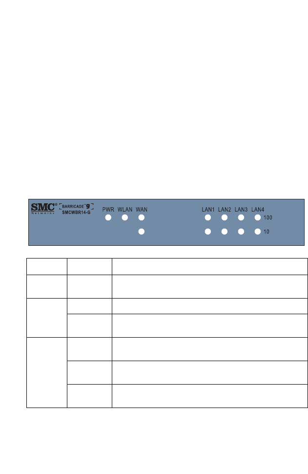
LED Indicators
The Wireless Barricade g Router includes status LED indicators,
as described in the following figure and table.
LED Status Description
PWR
(Green) On The Wireless Barricade is receiving power.
WLAN
(Green) On The Wireless LAN is enabled.
Flashing The Wireless Barricade is transmitting or receiving
traffic via a wireless connection.
WAN/
LAN1-4 Green On The indicated Ethernet port has established a valid
100 Mbps network connection.
Amber On The indicated Ethernet port has established a valid
10 Mbps network connection.
Flashing The indicated Ethernet port is transmitting or receiving
traffic.

About the Wireless Barricade g Router
2
Features and Benefits
•Internet connection to DSL or cable modem via
a 10/100 Mbps WAN port
•Local network connection via 10/100 Mbps Ethernet ports or
54 Mbps wireless interface
•IEEE 802.11g Compliant – interoperable with multiple
vendors
•Advanced security through 64/128-bit WEP encryption,
802.1x, SSID broadcast disabled, and MAC address filtering
features to protect your sensitve data and authenticate only
authorized users to your network
•Provides seamless roaming within 802.11g draft WLAN
environment
•DHCP for dynamic IP configuration, and DNS for domain
name mapping
•Firewall with Stateful Packet Inspection, client privileges,
hacker prevention, DoS, and NAT
•NAT also enables multi-user access with a single-user
account, and virtual server functionality such as web, mail,
FTP, and Telnet
•Virtual Private Network support using PPTP, L2TP, or IPSec
pass-through, ISP permitting
•Parental controls allow the user to restrict web browsing
•Automatic email alerts when the network is being attacked
•Easy setup through a web browser on any operating system
that supports TCP/IP
•Compatible with all popular Internet applications

3
INSTALLING THE WIRELESS
BARRICADE G ROUTER
Before installing the Wireless Barricade, verify that you have all
the items listed under “Package Contents.” If any of the items are
missing or damaged, contact your local SMC distributor. Also be
sure that you have all the necessary cabling before installing the
Wireless Barricade. After installing the Wireless Barricade, refer
to the web-based configuration program in “Configuring the
Wireless Barricade g Router” on page 20 for information on
configuring the Wireless Barricade.
Package Contents
After unpacking the Wireless Barricade, check the contents of
the box to be sure you have received the following components:
•Wireless Barricade g Broadband Router
•Power adapter
•One CAT-5 Ethernet cable
•Four rubber feet
•Installation CD containing this User Guide and EZ 3-Click
Installation Wizard
•Quick Installation Guide
Immediately inform your dealer in the event of any incorrect,
missing or damaged parts. If possible, please retain the carton
and original packing materials in case there is a need to return
the product.
Please register on SMC’s web site at www.smc.com
The Wireless Barricade is covered by a limited lifetime warranty.

Installing the Wireless Barricade g Router
4
Hardware Description
The Wireless Barricade can be connected to the Internet or to a
remote site using its WAN port. It can be connected directly to
your PC or to a local area network using any of the Fast Ethernet
LAN ports.
Although access speed to the Internet is determined by your
service type and the modem type connected to the Wireless
Barricade, data passing between the devices connected to your
local area network can run up to 100 Mbps over the Fast
Enternet ports.
The Wireless Barricade includes an LED display on the front
panel for system power and port indications that simplifies
installation and network troubleshooting. It also provides four
RJ-45 LAN ports and one RJ-45 WAN port on the rear panel.
•Four Ethernet ports for connection to a 10BASE-T/
100BASE-TX Ethernet Local Area Network (LAN). These
ports can auto-negotiate the operating speed to 10/100 Mbps,
the mode to half/full duplex, and the pin signals to MDI/MDI-X
(i.e., allowing these ports to be connected to any network
device with straight-through cable). These ports can be
connected directly to a PC or to a server equipped with an
Ethernet network interface card, or to a networking device
such as an Ethernet hub or switch.
•One RJ-45 port for connection to a DSL or cable modem
(WAN). This port also auto-negotiates operating speed to
10/100 Mbps, the mode to half/full duplex, and the pin signals
to MDI/MDI-X.
Hardware Description
5
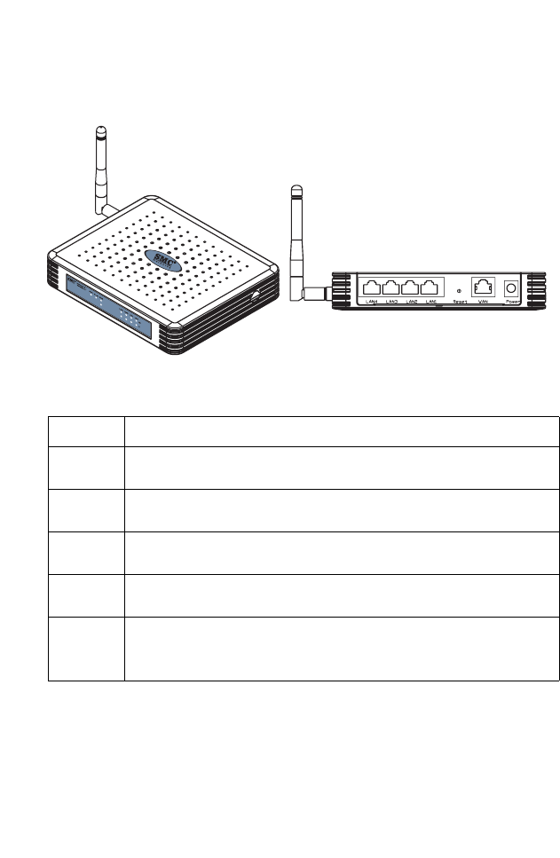
The following figure shows the components of the Wireless
Barricade:
Figure 1. Front and Rear Panels
Item Description
LEDs Power, WLAN, WAN and LAN port status indicators.
(See “LED Indicators” on page 1.)
LAN
Ports Fast Ethernet ports (RJ-45). Connect devices (such as a PC, hub
or switch) on your local area network to these ports.
Reset
Button Use this button to reset the power and restore the default factory
settings.
WAN
Port WAN port (RJ-45). Connect your cable modem, DSL modem, or an
Ethernet router to this port.
Power
Inlet Connect the included power adapter to this inlet.
Warning: Using the wrong type of power adapter may damage
your Wireless Barricade.

Installing the Wireless Barricade g Router
6
System Requirements
•Internet access from your local telephone company or Internet
Service Provider (ISP) using a DSL modem or cable modem.
•A PC using a fixed IP address or dynamic IP address
assigned via DHCP, as well as a gateway server address and
DNS server address from your service provider.
•A computer equipped with a 10 Mbps, 100 Mbps, or
10/100 Mbps Fast Ethernet card, or a USB-to-Ethernet
converter.
•TCP/IP network protocol installed on each PC that needs to
access the Internet.
•A Java-enabled web browser, such as Microsoft Internet
Explorer 5.5 or above, Firefox 1.0 or Mozilla 1.7 installed on
one PC at your site for configuring the Wireless Barricade.
Connect the System
The Wireless Barricade can be positioned at any convenient
location in your office or home. No special wiring or cooling
requirements are needed. You should, however comply with the
following guidelines:
•Keep the Wireless Barricade away from any heating devices.
•Do not place the Wireless Barricade in a dusty or wet
environment.
You should also remember to turn off the power, remove the
power cord from the outlet, and keep your hands dry when you
install the Wireless Barricade.
Connect the System
7
Basic Installation Procedure
1. Connect the LAN: Connect the Wireless Barricade to your
PC, or to a hub or switch. Run Ethernet cable from one of the
LAN ports on the rear of the Wireless Barricade to your
computer’s network adapter or to another network device.
You may also connect the Wireless Barricade to your PC
(using a wireless client adapter) via radio signals.
2. Connect the WAN: Use an Ethernet cable for connecting the
Wireless Barricade
to a cable/xDSL modem or Ethernet router.
3. Power on: Connect the power adapter to the Wireless
Barricade.
Figure 2. Example Network Configuration
Internet
Access
Device
Wireless
Router
Cable/DSL
Broadband
SOHO Office or Residence
Notebook with
Wireless PC Card
Internet
Installing the Wireless Barricade g Router
8
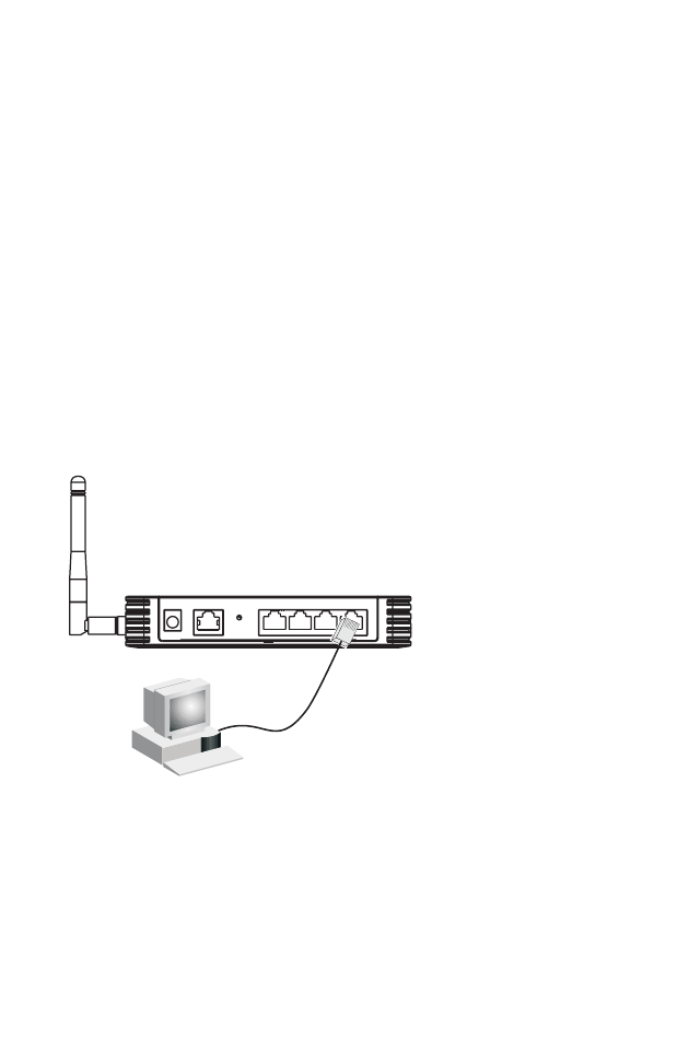
Attach to Your Network Using Ethernet Cabling
Use twisted-pair cable to connect any of the four LAN ports on
the Wireless Barricade to an Ethernet adapter on your PC.
Otherwise, you can cascade any of the LAN ports on the
Wireless Barricade to an Ethernet hub or switch, and then
connect your PC or other network equipment to the hub or
switch. When inserting an RJ-45 plug, be sure the tab on the plug
clicks into position to ensure that it is properly seated.
Warning: Do not plug a phone jack connector into any RJ-45
port. This may damage the Wireless Barricade.
Instead, use only twisted-pair cables with RJ-45
connectors that conform with FCC standards.
Figure 3. Making a LAN Connection
Connect the System
9
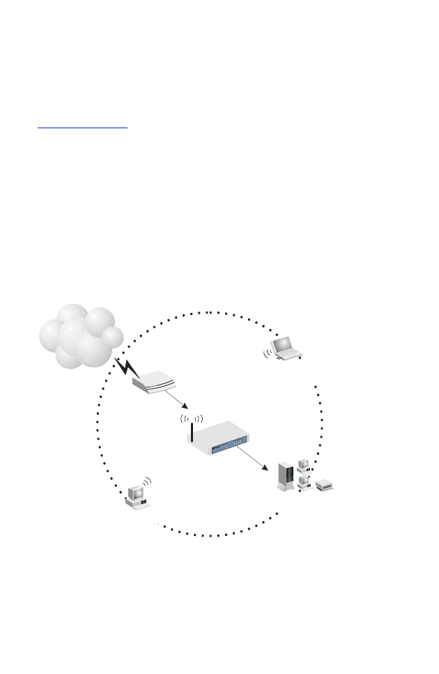
Attach to Your Network Using Radio Signals
Install a wireless network adapter in each computer that will be
connected to the Internet or your local network via radio signals.
SMC currently offers several wireless network cards,
please visit
www.smc.com
for more details.
Try to place the Wireless Barricade in a position that is located in
the center of
your wireless network. Normally, the higher you
place the antenna,
the better the performance. Ensure that the
Wireless Barricade’s location provides optimal reception
throughout your home or office.
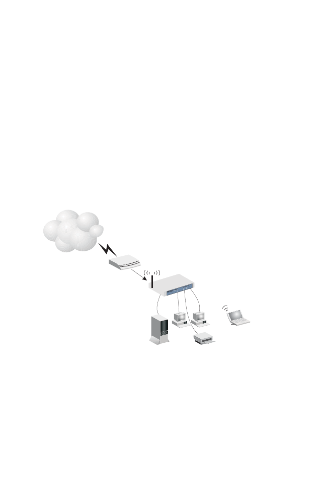
A wireless infrastructure can be used for access to a central
database, or for connection between mobile workers, as shown
in the following figure:
Figure 4. WLAN Connection Example
Internet
Access
Device
Wireless
Router
Cable/DSL
Broadband
Notebook with Wireless
PC Card Adapter
PC with Wireless
PCI Adapter
Wired LAN
Internet
Installing the Wireless Barricade g Router
10
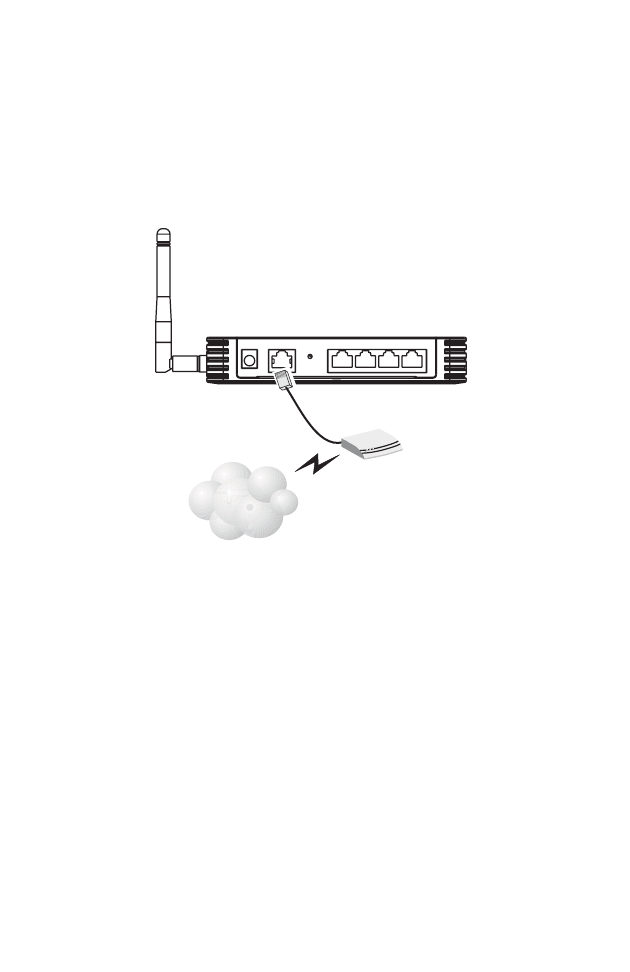
Attach the Wireless Barricade g Router to the Internet
If Internet services are provided through an xDSL or cable
modem, use unshielded or shielded twisted-pair Ethernet cable
CAT 5 with RJ-45 plugs to connect the broadband modem
directly to the WAN port on the Wireless Barricade.
Figure 5. WAN Connection Example
ISP
(primary)
DSL/Cable
Modem

11
CONFIGURING
CLIENT TCP/IP
To access the Internet through the Wireless Barricade, you must
configure the network settings of the computers on your LAN to
use the same IP subnet as the Wireless Barricade. The default
network settings for the Wireless Barricade are:
Gateway IP Address: 192.168.2.1
Subnet Mask: 255.255.255.0
Note: These settings may be changed to suit your network
requirements, but you must first configure at least one
computer as described in this chapter to access the
Wireless Barricade’s web configuration interface. See
“Configuring the Wireless Barricade g Router” on
page 20 for information on configuring the Wireless
Barricade.
The IP address of the connected client PC should be 192.168.2.x
(where x means 2–254). You can set the IP address for client
PCs either by automatically obtaining an IP address from the
Wireless Barricade’s DHCP service or by manual configuration.
Configuring Client TCP/IP
12
Configuring Your Computer in Windows 2000
1. Access your Network settings by clicking Start, then choose
Settings and then select Control Panel.
2. In the Control Panel, locate and double-click the Network and
Dial-up Connections icon.
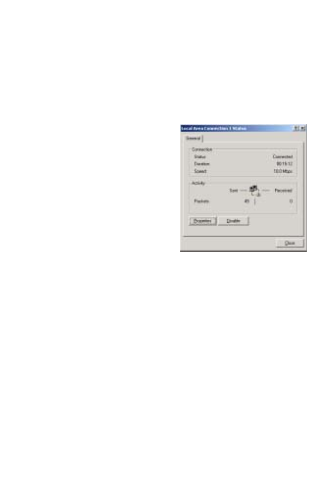
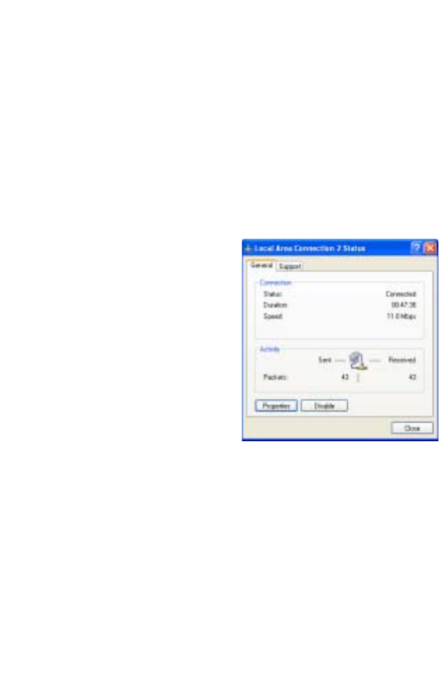
3. Locate and double-click the
Local Area Connection icon
for the Ethernet adapter that
is connected to the Wireless
Barricade. When the Status
dialog box window opens,
click the Properties button.
4. In the Local Area Connection
Properties box, verify the box
next to Internet Protocol
(TCP/IP) is checked. Then
highlight the Internet Protocol (TCP/IP), and click the
Properties button.
5. Select “Obtain an IP address automatically” to configure your
computer for DHCP. Click the OK button to save this change
and close the Properties window.
6. Click the OK button again to save these new changes.
7. Reboot your PC.
8. To obtain new network settings see See “Obtain IP Settings
from Your Wireless Barricade g Router” on the next page.
Configuring Client TCP/IP
13
Obtain IP Settings from Your Wireless Barricade g Router
Now that you have configured your computer to connect to the
Wireless Barricade, it needs to obtain new network settings. By
releasing old IP settings and renewing them with settings from
the Wireless Barricade, you will also verify that you have
configured your computer correctly.
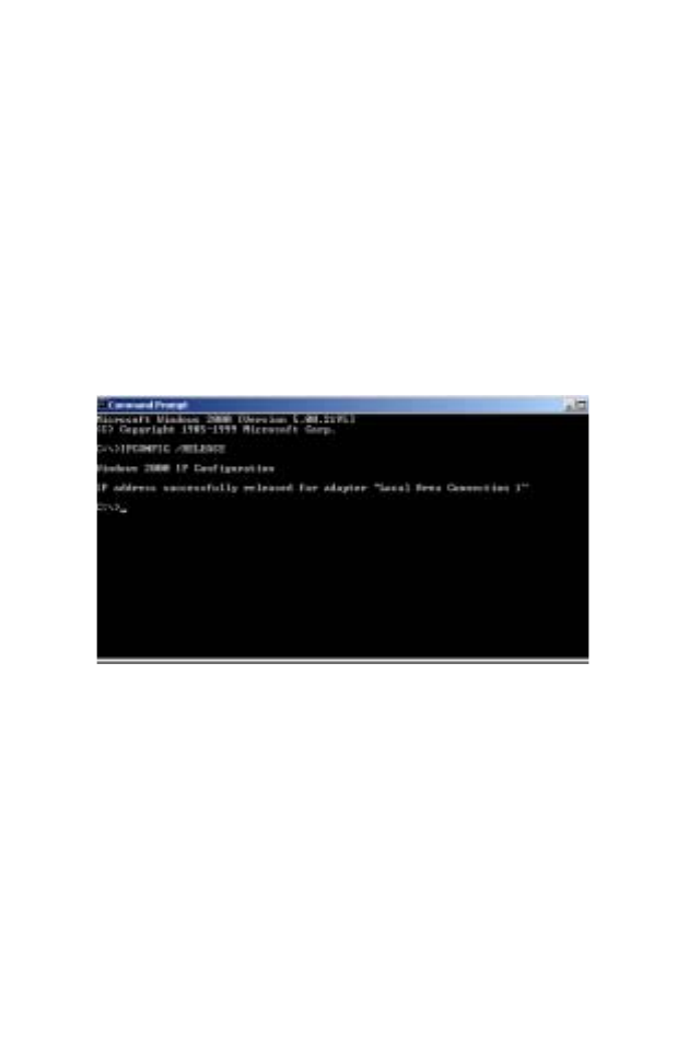
1. On the Windows desktop, click Start/Programs/Command
Prompt.
2. In the Command Prompt window, type IPCONFIG /RELEASE
and press the <ENTER> key.
Configuring Client TCP/IP
14
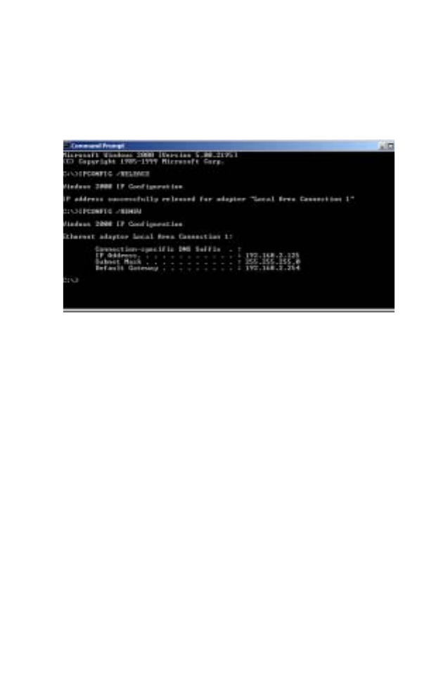
3. Type IPCONFIG /RENEW and press the <ENTER> key. Verify
that your IP Address is now 192.168.2.xxx, your Subnet Mask
is 255.255.255.0 and your Default Gateway is 192.168.2.1.
These values confirm that the Wireless Barricade is
functioning.
4. Type EXIT and press <ENTER> to close the Command
Prompt window.
Configuring Client TCP/IP
15
Configuring Your Computer in Windows XP
The following instructions assume you are running Windows XP
with the default interface. If you are using the Classic interface
(where the icons and menus look like previous Windows
versions), please follow the instructions for Windows 2000
outlined above.
1. Access your Network settings by clicking Start, choose
Control Panel, select Network and Internet Connections and
then click on the Network Connections icon.
2. Locate and double-click the
Local Area Connection icon
for the Ethernet adapter that
is connected to the Wireless
Barricade. Next, click the
Properties button.
3. In the Local Area Connection Properties box, verify the box
next to Internet Protocol (TCP/IP) is checked. Then highlight
the Internet Protocol (TCP/IP), and click the Properties
button.
4. Select “Obtain an IP address automatically” to configure your
computer for DHCP. Click the OK button to save this change
and close the Properties window.
5. Click the OK button again to save these new changes.
6. Reboot your PC.
Configuring Client TCP/IP
16
Configuring a Macintosh Computer
You may find that the instructions here do not exactly match your
screen. This is because these steps and screen shots were
created using Mac OS 10.2. Mac OS 7.x and above are all very
similar, but may not be identical to Mac OS 10.2.
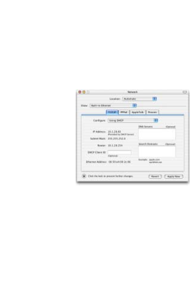
1. Pull down the Apple Menu. Click System Preferences and
select Network.
2. Make sure that
Built-in Ethernet
is selected in the
Show field.
3. On the TCP/IP
tab, select Using
DHCP in the
Configure field.
4. Close the
TCP/IP dialog
box.
Configuring Client TCP/IP
17
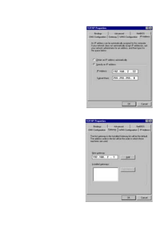
Manual IP Configuration (for all Windows OS)
1. Check Specify an IP
address on the IP Address
tab. Enter an IP address
based on the default
network 192.168.2.x (where
x is
between 2 and 254), and
use 255.255.255.0 for the
subnet mask.
2. In the Gateway tab, add the
IP address of the Wireless
Barricade
(default:
192.168.2.1)
in the New
gateway field and click Add.
Configuring Client TCP/IP
18
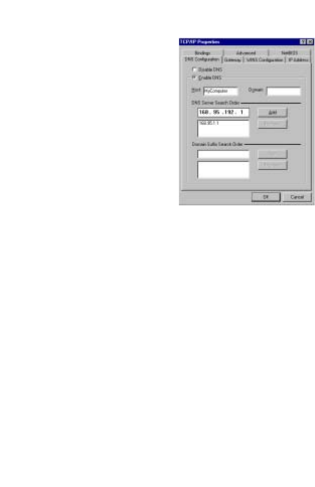
3. On the DNS Configuration
tab, add the IP address for
the Wireless Barricade and
click Add. This automatically
relays DNS requests to the
DNS server(s) provided by
your ISP. Otherwise, add
specific DNS servers into
the DNS Server Search
Order field and click Add
.
4. After finishing TCP/IP setup,
click OK, and then reboot
the computer. After that, set
up other PCs on the LAN
according to the procedures described above.

Configuring Client TCP/IP
19
Verifying Your TCP/IP Connection
After installing the TCP/IP communication protocols and
configuring an IP address in the same network as the Wireless
Barricade, use the ping command to check if your computer has
successfully connected to the Wireless Barricade. The following
example shows how the ping procedure can be executed in an
MS-DOS window. First, execute the ping command:
ping 192.168.2.1
If a message similar to the following appears:
Pinging 192.168.2.1 with 32 bytes of data:
Reply from 192.168.2.1: bytes=32 time=2ms TTL=64
a communication link between your computer and the Wireless
Barricade has been successfully established.
If you get the following message,
Pinging 192.168.2.1 with 32 bytes of data:
Request timed out.
there may be something wrong in your installation procedure.
Check the following items in sequence:
1. Is the Ethernet cable correctly connected between the
Wireless Barricade and the computer?
The LAN LED on the Wireless Barricade and the Link LED of
the network card on your computer must be on.
2. Is TCP/IP properly configured on your computer?
If the IP address of the Wireless Barricade is 192.168.2.1, the
IP address of your PC must be from 192.168.2.2-254 and the
default gateway must be 192.168.2.1.
If you can successfully ping the Wireless Barricade you are
now ready to connect to the Internet!

20
C
ONFIGURING THE
W
IRELESS
B
ARRICADE G
R
OUTER
The Wireless Barricade g Router can be configured by Internet
Explorer 5.5 or above. Using the web management interface, you
can configure the Wireless Barricade and view statistics to
monitor network activity.
Note: Before you attempt to configure your Wireless
Barricade, if you have access to the Internet please
visit www.smc.com and download the latest firmware
update to ensure your Wireless Barricade is running
the latest firmware.
Before you attempt to log into the web-based administration,
please verify the following.
1. Your browser is configured properly (see below).
2. Disable any firewall or security software that may be running.
3. Confirm that you have a good link LED where your computer
is plugged into the Wireless Barricade. If you don’t have a link
light, then try another cable until you get a good link.
Browser Configuration
Confirm your browser is configured for a direct connection to the
Internet using the Ethernet cable that is installed in the computer.

Browser Configuration
21
Disable Proxy Connection
You will also need to verify that the HTTP Proxy feature of your
web browser is disabled. This is so that your web browser will be
able to view the Wireless Barricade configuration pages. The
following steps are for Internet Explorer.
Internet Explorer 5.5 or above (For Windows)
1. Open Internet Explorer. Click Tools, and then select Internet
Options.
2. In the Internet Options window, click the Connections tab.
3. Click the LAN Settings button.
4. Clear all the check boxes and click OK to save these LAN
settings changes.
5. Click OK again to close the Internet Options window.
Internet Explorer (For Macintosh)
1. Open Internet Explorer. Click Explorer/Preferences.
2. In the Internet Explorer Preferences window, under Network,
select Proxies.
3. Uncheck all check boxes and click OK.
Configuring the Wireless Barricade g Router
22
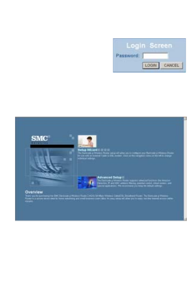
Navigating the Web Browser Interface
To access the Wireless Barricade’s
management interface, enter the
Wireless Barricade IP address in
your web browser http://192.168.2.1.
Then click LOGIN.
(Default password: smcadmin)
Note: Login passwords are case sensitive.
The home page displays the Setup Wizard and Advanced Setup
options.
Use the Setup Wizard if you want to quickly set up the Wireless
Barricade for use with a cable modem or DSL modem.
Advanced setup supports more advanced functions like hacker
attack detection, IP and MAC address filtering, intrusion
detection, virtual server setup, virtual DMZ hosts, and other
advanced functions.

Navigating the Web Browser Interface
23
Making Configuration Changes
Configurable parameters have a dialog box or a drop-down list.
Once a configuration change has been made on a page, be sure
to click the APPLY or NEXT button at the bottom of the page to
enable the new setting.
Note: To ensure proper screen refresh after a command
entry, ensure that Internet Explorer 5.5 is configured as
follows: Under the menu Tools/Internet Options/
General/Temporary Internet Files/Settings, the setting
for “Check for newer versions of stored pages” should
be “Every visit to the page.”
Configuring the Wireless Barricade g Router
24
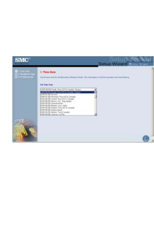
Setup Wizard
Time Zone
Click on the Setup Wizard picture. The first item in the Setup
Wizard is Time Zone setup.
For accurate timing of client filtering and log events, you need to
set the time zone. Select your time zone from the drop-down list.
Setup Wizard
25
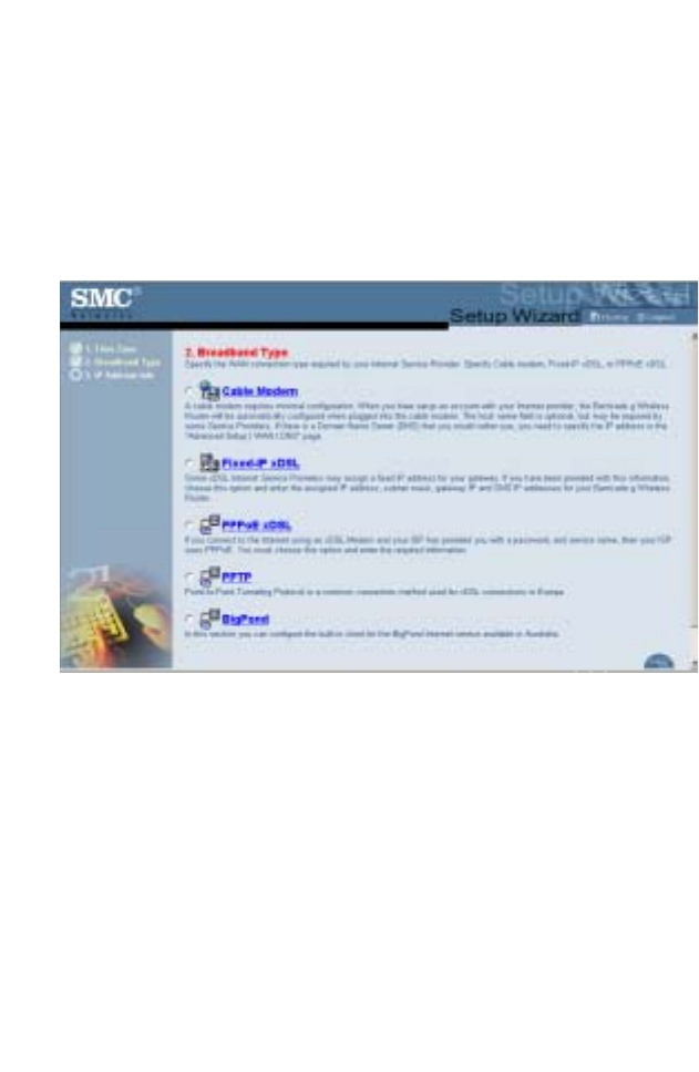
Broadband Type
Select the type of broadband connection you have.
For a cable modem connection see the following page. For a
Fixed-IP xDSL connection see “Fixed-IP xDSL” on page 26, for a
PPPoE xDSL connection, see “PPPoE” on page 27, and for
BigPond connection, see “BigPond” on page 29.
Configuring the Wireless Barricade g Router
26
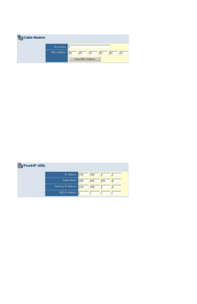
Cable Modem
Your Internet Service Provider may have given you a host name.
If so, enter it into the field. If your ISP used the MAC address of
an Ethernet card as an identifier when first setting up your
broadband account, only connect the PC with the registered
MAC address to the Wireless Barricade and click the Clone MAC
Address button. This will replace the current Wireless Barricade
MAC address with the already registered Ethernet card MAC
address.
Click Finish to complete the setup.
Fixed-IP xDSL
Some xDSL Internet Service Providers may assign a fixed
(static) IP address. If you have been provided with this
information, choose this option and enter the assigned IP
address, subnet mask, gateway IP address, and DNS IP
address. Click FINISH to complete the setup.

Setup Wizard
27
PPPoE
Enter the PPPoE User Name and Password assigned by your
Service Provider. The Service Name is normally optional, but
may be required by some service providers.
Leave the Maximum Transmission Unit (MTU) at the default
value (1454) unless you have a particular reason to change it.
Enter a Maximum Idle Time (in minutes) to define a maximum
period of time for which the Internet connection is maintained
during inactivity. If the connection is inactive for longer than the
Maximum Idle Time, it will be dropped. (Default: 10)
Enable the Auto-reconnect option to automatically re-establish
the connection as soon as you attempt to access the Internet
again.
Note: If you are on a leased line or pay-per min. connection,
please set your maximum idle time to 3 minutes. This
will cause your Internet connection to drop after 3
minutes of idle time so you won’t be charged for extra
online time from your ISP.
Click FINISH to complete the setup.

Configuring the Wireless Barricade g Router
28
Point-to-Point Tunneling Protocol (PPTP)
Point-to-Point Tunneling Protocol is a common connection
method used for xDSL connections in Europe. It can be used to
join different physical networks using the Internet as an
intermediary.
If you have been provided with the information as shown on the
screen, enter the PPTP Account name and password, Host
Name, Service IP Address, the assigned IP Address, and Subnet
Mask.
Leave the Maximum Transmission Unit (MTU) at the default
value (1460) unless you have a particular reason to change it.
Enter a Maximum Idle Time (in minutes) to define a maximum
period of time for which the Internet connection is maintained
during inactivity. If the connection is inactive for longer than the
Maximum Idle Time, it will be dropped. (Default: 10)
Enable the Auto-reconnect option to automatically re-establish
the connection as soon as you attempt to access the Internet
again.
Note: If you are on a leased line or pay-per min. connection,
please set your maximum idle time to 3 minutes. This
will cause your Internet connection to drop after 3
minutes of idle time so you won’t be charged for extra
online time from your ISP.
Click FINISH to complete the setup.
Advanced Setup
29
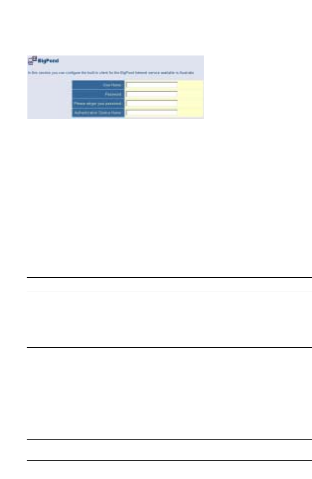
BigPond
If you use the BigPond Internet Service which is available in
Australia, enter the the User Name, Password and Authentication
Service Name for BigPond authentication. Click FINISH to
complete the setup.
Advanced Setup
Use the web management interface to define system
parameters, manage and control the Wireless Barricade and its
ports, or monitor network conditions. The following table outlines
the selections available from this program.
Menu Description
System • Sets the local time zone, the password for administrator
access, the Internet security of ZoneAlarm Pro (optional),
system log server, and the IP address of a PC that will be
allowed to manage the Wireless Barricade remotely.
• Sets enhanced security policy for the network using Zone
Labs, Inc.
WAN Specifies the Internet connection type:
• Dynamic IP host configuration and the physical MAC address
of each media interface
• PPPoE configuration
• PPTP configruation
• Static IP and ISP gateway address
• BigPond (Internet service available in Australia)
• Specifies DNS servers to use for domain name resolution.
LAN Sets the TCP/IP configuration of the Wireless Barricade’s LAN
interface and all DHCP clients.

Configuring the Wireless Barricade g Router
30
Wireless Configures the radio frequency, SSID, encryption and 802.1x
security, and WDS for wireless communications.
NAT Shares a single ISP account with multiple users, sets up virtual
servers.
Firewall Configures a variety of security and specialized functions,
including: Access Control, Hacker Prevention, and DMZ.
DDNS Dynamic DNS provides users on the Internet with a method to
tie their domain name to a computer or server.
UPnP With Universal Plug and Play, a device can automatically join a
network, obtain an IP address, communicate its capabilities, and
learn about the presence and capabilities of other devices.
Devices can then directly communicate with each other. This
further enables peer-to-peer networking.
Tools Contains options to back up and restore the current
configuration, restore all configuration settings to the factory
defaults, update system firmware, or reset the system.
Status Provides WAN connection type and status, firmware and
hardware version numbers, system IP settings, as well as
DHCP, NAT, and Firewall information.
Displays the number of attached clients, the firmware versions,
the physical MAC address for each media interface, and the
hardware version and serial number.
Shows the security and DHCP client log.
Menu Description
Advanced Setup
31
System
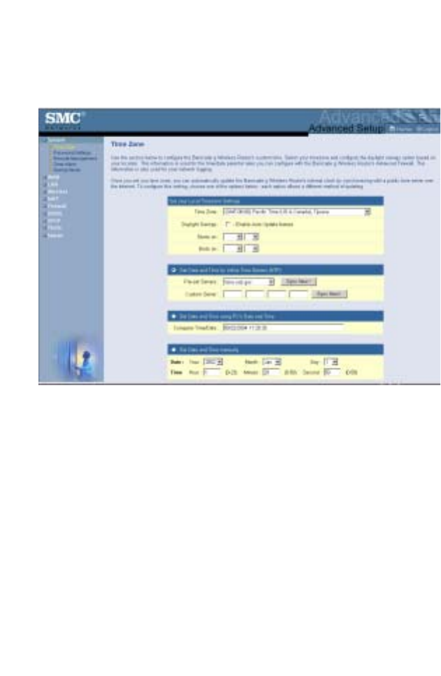
Time Zone
Set the time zone and time server for the Wireless Barricade.
This information is used for log entries and client access control.
•Set your local time zone settings
Select your time zone from the drop-down list, and set the start
and end dates if your area requires daylight savings.
To automatically update the Wireless Barricade’s internal clock
by synchronizing with a public time server over the Internet,
choose one of the methods below.

Configuring the Wireless Barricade g Router
32
•Get date and time from online time servers (Network Time
Protocol)
Choose the online standard time server for your area from the
drop-down menu, or enter the IP address of the time server on
your network.
•Set date and time using the PC's date and time
Click on the radio button for synchronizing the Wireless
Barricade’s internal clock with the host PC.
•Set date and time manually
For manually setting the date and time, configure the date by
selecting the options from the drop-down list, and enter the digits
for the time.
Advanced Setup
33
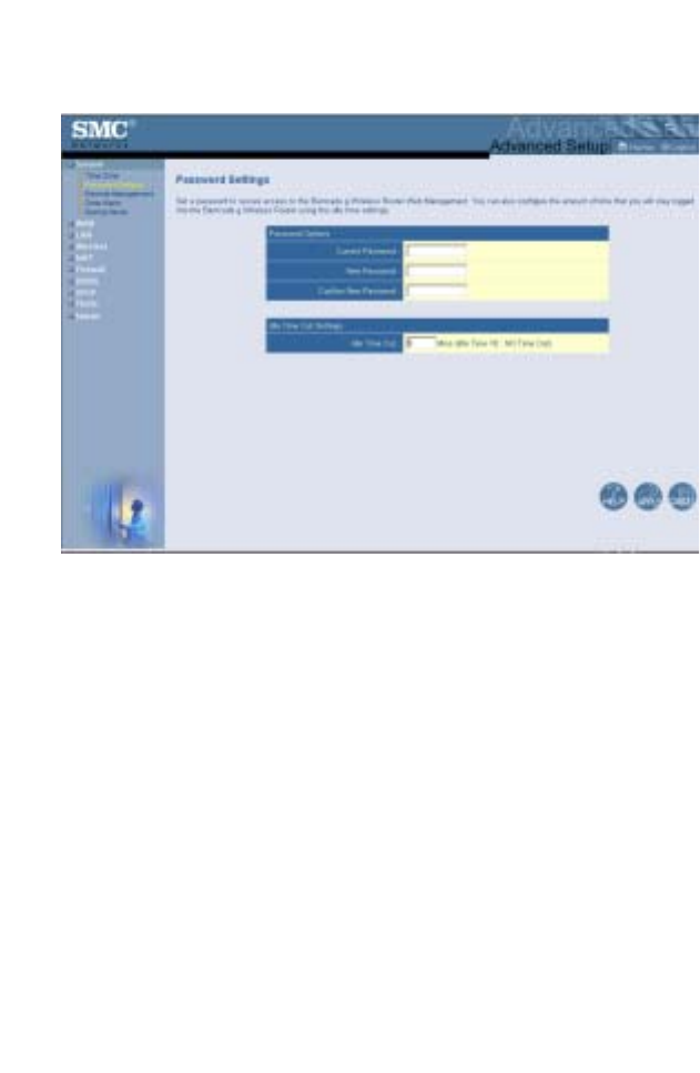
Password Settings
Use this menu to restrict access based on a password. For
security you should assign your own password before exposing
the Wireless Barricade to the Internet. (Default: smcadmin)
Passwords can contain from 3 to 12 alphanumeric characters
and are case sensitive.
Note: If your password is lost, or you cannot gain access to
the user interface, press the Reset button on the rear
panel (holding it down for at least five seconds) to
restore the factory defaults.
Enter a maximum Idle Time Out (in minutes) to define a
maximum period of time for which the login session is maintained
during inactivity. If the connection is inactive for longer than the
maximum idle time, it will perform system logout, and you have to
log into the web management system again.
(Default: 10 minutes)
Configuring the Wireless Barricade g Router
34
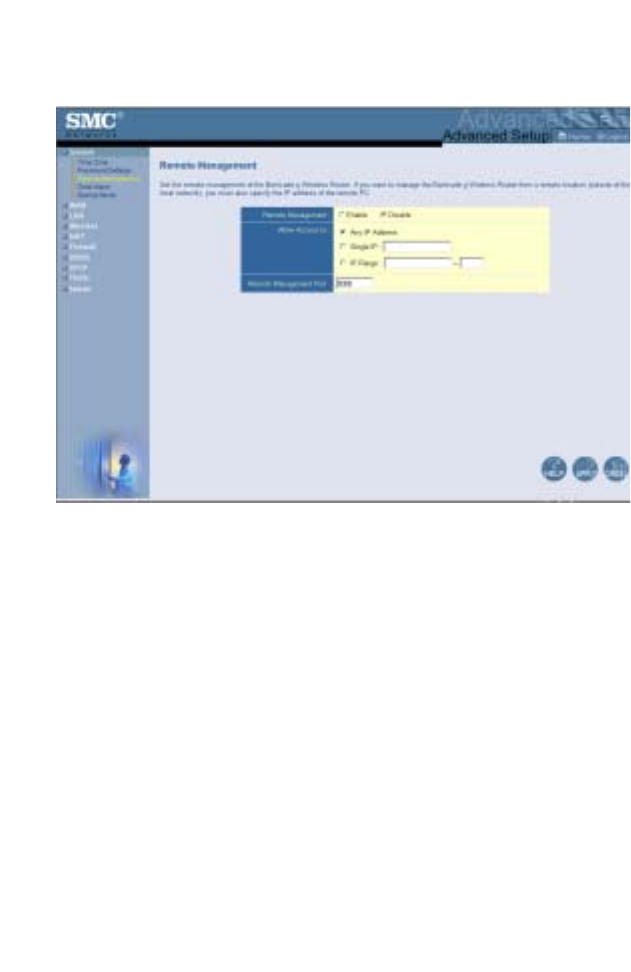
Remote Management
Remote Management allows a remote PC to configure, manage,
and monitor the Wireless Barricade using a standard web
browser. Check Enable and set the IP address (range) of the
remote host. Click APPLY. (Default: Disable)
Note: If you select Any IP Address in the Allow Access to
field, any host can manage the Wireless Barricade.

Advanced Setup
35
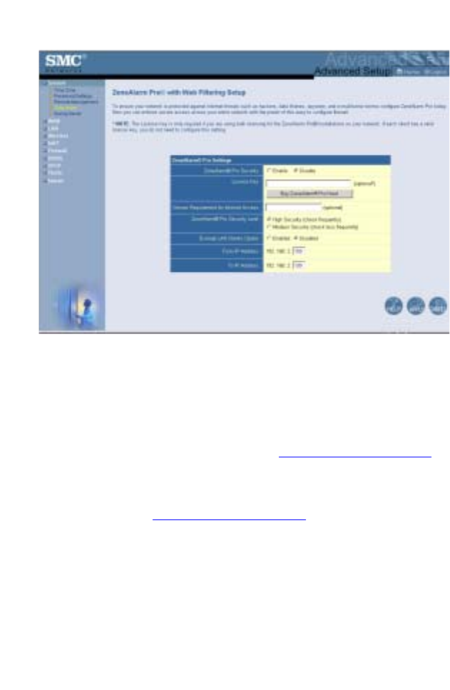
ZoneAlarm Pro® with Web Filtering Setup
Your Wireless Barricade now includes a new “Client
Enforcement” feature from Zone Labs, Inc. Client Enforcement
provides end to end security by ensuring that only protected
endpoint PC’s have access to the network. Simply configure your
Wireless Barricade to restrict the network access of endpoint
PCs that are not in compliance with security requirements. This
easy-to-use feature allows you to ensure each of your PCs is
safe from Trojan horse and spy-ware style attacks.
ZoneAlarm® Pro protects your PC from both known and unknown
threats with a combination of:
• Stealth firewall that protects each individual computer in your
network, and travels with that computer wherever it goes.
Mobile endpoint protection is a must for traveling laptops;
• Program Control to manage which applications are
connecting to the Internet, blocking spy-ware and other
malicious software from sending your personal information
out from your computer;
• MailSafe to identify and quarantine potentially harmful email
attachments (coming in and going out), to prevent email
viruses, worms and Trojans disguised as attachments from
getting onto to your machine and mass-email worms from
sending viruses out to the people in your address book; and

Configuring the Wireless Barricade g Router
36
• Privacy protection to keep your identity and web-surfing
habits confidential with features such as cookie control,
3rd-party spy protection and cache cleaner to protect your
privacy while you surf, and ad-blocking and parental control
keep your surfing safe and distraction-free.
By refusing Internet or WAN access to any workstation not
running ZoneAlarm Pro, security of your network is greatly
increased. You can easily make exceptions for individual
workstations at your discretion. When an Internet request is
rejected, the user will be routed to http://smc.zonelabs.com
where (s)he will be given the option to purchase ZoneAlarm Pro
or upgrade to the proper version required by the policy.
The option does not significantly affect system performance, so
we advise enabling it to protect your network users. Select
Enable and click the APPLY button.
Note: When you select the Enable radio button in the Enable
or Disable ZoneAlarm® Pro Security field, be sure to
press the APPLY button.
Advanced Setup
37
•License Key
The License Key field is optional. To input your ZoneAlarm Pro
(ZAP) License Number, type in or paste the license number you
received at the time of purchase.
Note: Only licenses for ZoneAlarm Pro with Web Filtering 4.x
and higher,
purchased through http
://smc.zonelabs.com,
can be inserted directly into this field.
Click the Buy ZoneAlarm Pro Now! to purchase a license.You will
be directed to the http://smc.zonelabs.com web site where you
can complete your product purchase.
•Version Requirement for Internet Access
The Version Requirement for the Internet Access field is an
optional setting. This field gives you even tighter control over the
enforcement of ZoneAlarm Pro software. In addition to requiring
ZoneAlarm Pro software for network access, you can also
specify what version of ZoneAlarm Pro users need to run to

Configuring the Wireless Barricade g Router
38
ensure that users always run the most up-to-date version of the
software.
•ZoneAlarm Pro Security Level
The overhead for communication between the router and Zone
Alarm Pro with Web Filtering on your PCs is very minimal. The
communication packets are small and infrequent. However, if you
do feel it is causing a delay on your network, you have some
control over the frequency the packets are sent to and from
ZoneAlarm Pro and the Wireless Barricade.
On the ZoneAlarm Pro (ZAP) Settings Panel on the Wireless
Barricade, the ZAP Security Level option tells the Wireless
Barricade and ZoneAlarm Pro how often they should
communicate. This communication tells the Wireless Barricade
that ZoneAlarm Pro is still running on the PC.
If you set this option to High Security (Check Frequently), the
exchange will occur at smaller intervals. Though we feel this
should not impact your network performance, you do have the
option to select Medium Security (Check Less Frequently) to
increase the interval.
•Exempt LAN Clients Option
This option allows you to Enable or Disable the creation of a
range of IP addresses for PCs which are non–Windows or
require exemption from this enforcement policy.
Note: This option is set as Disabled by default. When you
select the Enabled radio button in the Exempt LAN
Client Option field, be sure to press the APPLY button.
•From IP Address
Input the last three digits of the first IP Address from the range of
IP addresses that you would like to exempt from this policy
enforcement.
Advanced Setup
39
Note: The default IP address of the Wireless Barricade is
192.168.2.1. The IP address that can be assigned to a
PC workstation on the network is 192.168.2.x (where x
means 2–254). See “Configuring Client TCP/IP” on
page 11.
•To IP Address
Input the last three digits of the last IP Address from the range of
IP addresses that you would like to exempt from this policy
enforcement.
Note: You also need to make sure that Exempt LAN Client
Option is set to Enable. Be sure to press the APPLY
button after completing the entry.
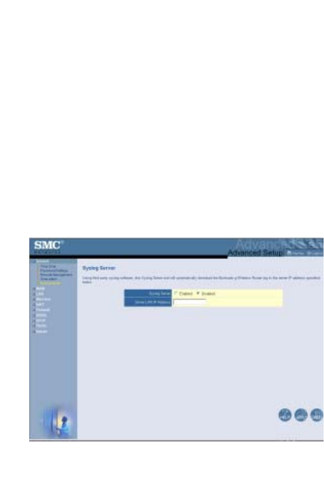
Syslog Server
The Syslog Server downloads the Wireless Barricade’s log file to
the server with the IP address specified on this screen.
(Default: Disabled)
Configuring the Wireless Barricade g Router
40
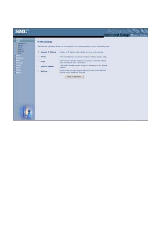
WAN
Specify the WAN connection type provided by your Internet
Service Provider, then click More Configuration to enter detailed
configuration parameters for the selected connection type.
Advanced Setup
41
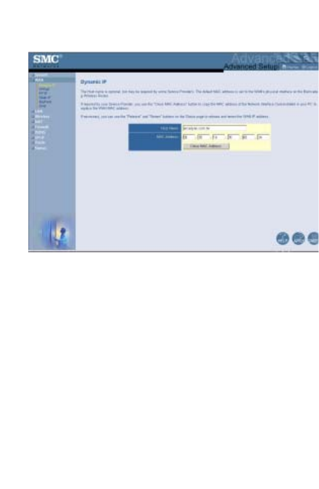
Dynamic IP
The Host Name is optional, but may be required by some ISPs.
The default MAC address is set to the WAN’s physical interface
on the Wireless Barricade. Use this address when registering for
Internet service, and do not change it unless required by your
ISP. If your ISP used the MAC address of an Ethernet card as an
identifier when first setting up your broadband account, only
connect the PC with the registered MAC address to the Wireless
Barricade and click the Clone MAC Address button. This will
replace the current Wireless Barricade MAC address with the
already registered Ethernet card MAC address. If you are unsure
of which PC was originally set up by the broadband technician,
call your ISP and request that they register a new MAC address
for your account. Register the default MAC address of the
Wireless Barricade.
Configuring the Wireless Barricade g Router
42
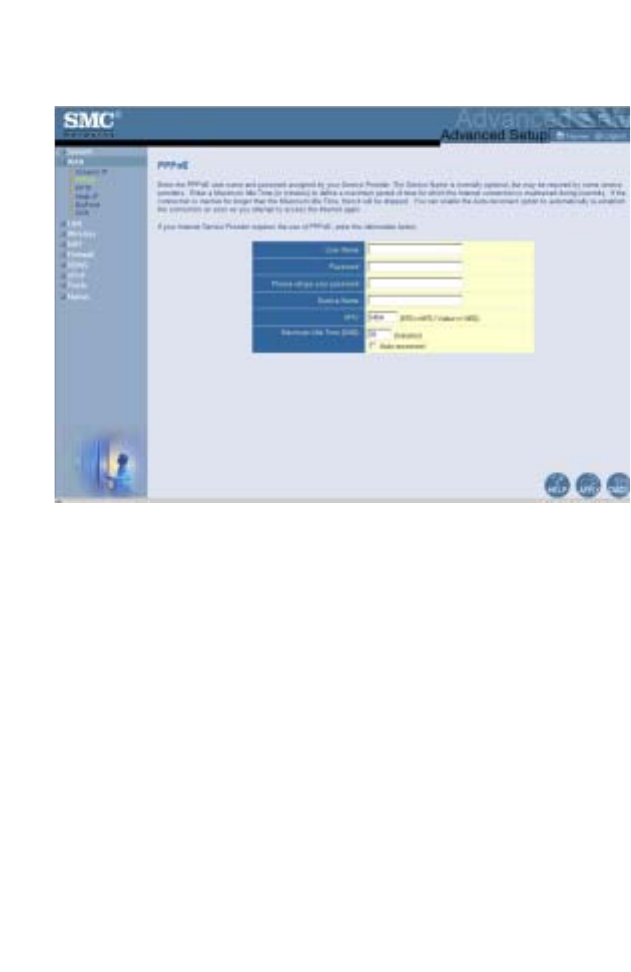
Point-to-Point Over Ethernet (PPPoE)
Enter the PPPoE User Name and Password assigned by your
Service Provider. The Service Name is normally optional, but
may be required by some service providers.
The MTU (Maximum Transmission Unit) governs the maximum
size of the data packets. Leave this on the default value (1454)
unless you have a particular reason to change it.
Enter a Maximum Idle Time (in minutes) to define a maximum
period of time for which the Internet connection is maintained
during inactivity. If the connection is inactive for longer than the
Maximum Idle Time, it will be dropped. (Default: 10 minutes)
Enable the Auto-reconnect option to automatically re-establish
the connection as soon as you attempt to access the Internet
again.
Advanced Setup
43
Note: If you are on a leased line or pay-per min. connection,
please set your maximum idle time to 3 minutes. This
will cause your Internet connection to drop after 3
minutes of idle time so you won’t be charged for extra
online time from your ISP.
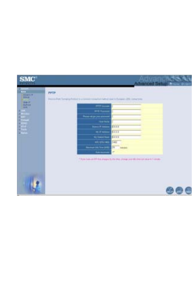
Point-to-Point Tunneling Protocol (PPTP)
Point-to-Point Tunneling Protocol (PPTP) can be used to join
different physical networks using the Internet as an intermediary.
Using the above screen allows client PCs to establish a normal
PPTP session and provides hassle-free configuration of the
PPTP client on each client PC.
Enter the PPTP Account, Password, Host Name, and then
Service IP Address (usually supplied by your ISP), the assigned
IP address, and subnet mask.
Leave the Maximum Transmission Unit (MTU) at the default
value (1460) unless you have a particular reason to change it.
Configuring the Wireless Barricade g Router
44
Enter a maximum Idle Time Out (in minutes) to define a
maximum period of time for which the PPTP connection is
maintained during inactivity. If the connection is inactive for
longer than the Maximum Idle Time, it will be dropped.
(Default: 0 minutes)
Note: If you are on a leased line or pay-per min. connection,
please set your maximum idle time to 3 minutes. This
will cause your Internet connection to drop after 3
minutes of idle time so you won’t be charged for extra
online time from your ISP.
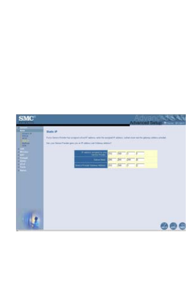
Static IP
If your Internet Service Provider has assigned a fixed IP address,
enter the assigned address and subnet mask for the Wireless
Barricade, then enter the gateway address of your ISP.
You may need a fixed address if you want to provide Internet
services, such as a web server or FTP server.
Advanced Setup
45
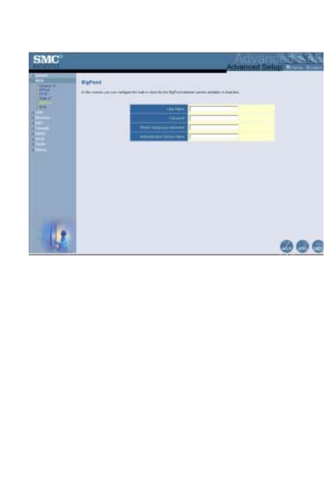
BigPond
BigPond is a service provider in Australia that uses a heartbeat
system to maintain the Internet connection. Configure the built-in
client with your user name, password and service name to get on
line.
Configuring the Wireless Barricade g Router
46
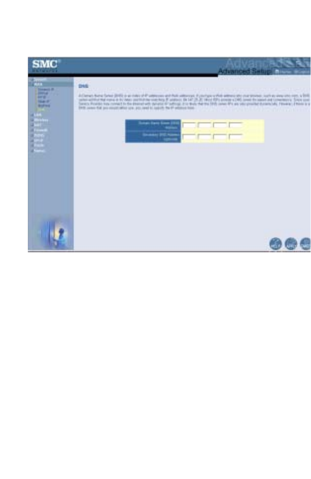
DNS
Domain Name Servers map numerical IP addresses to the
equivalent domain name (e.g., www.smc.com). Your ISP should
provide the IP address of one or more domain name servers.
Enter those addresses in this screen.
Advanced Setup
47
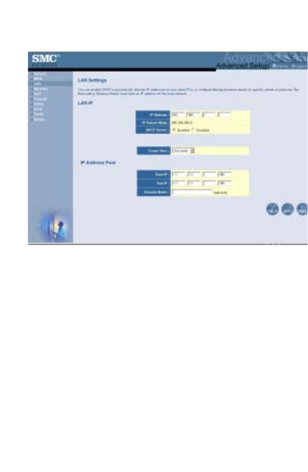
LAN
•LAN IP – Use the LAN menu to configure the LAN IP address
for the Wireless Barricade and to enable the DHCP server for
dynamic client address allocation.
•Set a period for the lease time if required. For home networks
this may be set to Forever, which means there is no time limit
on the IP address lease.
•IP Address Pool – A dynamic IP address range may be
specified (192.168.2.2–254). IP addresses running from
192.168.2.100–199 are the default values. Once the IP
addresses, e.g. 192.168.2.100–199, have been assigned,
these IP addresses will be part of the dynamic IP address
pool. IP addresses from 192.168.2.2–99, and
192.168.2.200–254 will be available as static IP addresses.
Remember not to include the address of the Wireless Barricade
in the client address pool. Also remember to configure your client
PCs for dynamic IP address allocation.
Configuring the Wireless Barricade g Router
48
Wireless
The Wireless Barricade can easily be configured as a Wireless
Access Point, so the wireless clients can connect directly to it to
form a wireless network. The wireless PCs must be set to
infrastructure mode to communicate with the Access Point.
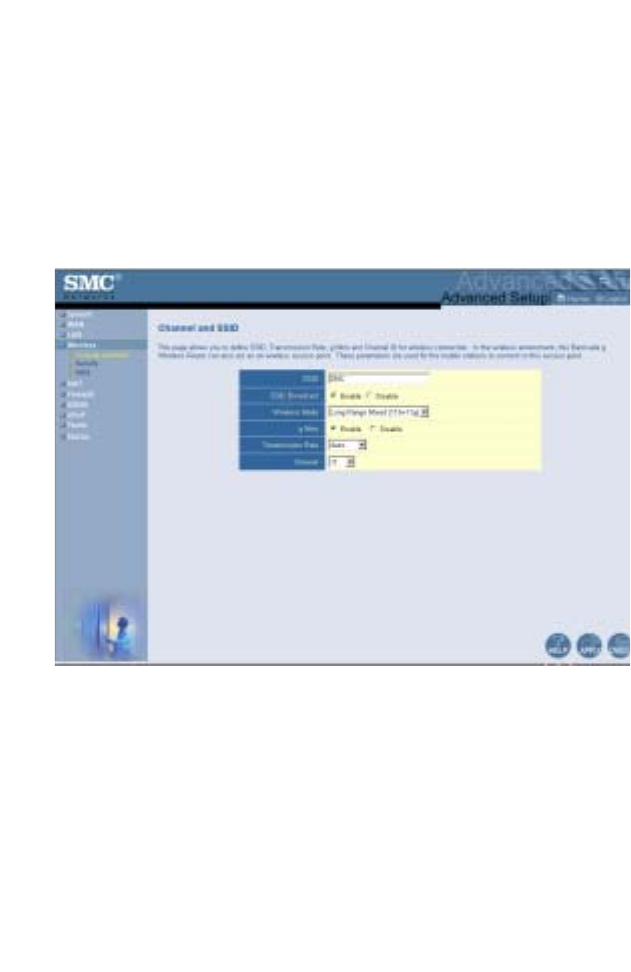
Channel and SSID
To create a wireless network, the Wireless Barricade and
wireless PCs must have the same Service Set ID (SSID),
encryption settings and channel number. The wireless settings
for the Wireless Barricade are described below:
SSID: The Service Set ID (SSID) is the name given to your
wireless LAN. Only PCs with the same SSID as the Wireless
Barricade can connect to the wireless LAN. (Default is SMC)
Note: The SSID is case sensitive and can consist of up to 32
alphanumeric characters.
Advanced Setup
49
SSID Broadcast: By default, the Wireless Barricade will transmit
the SSID in the wireless beacons as part of the normal wireless
protocol. To increase your wireless security the SSID Broadcast
can be disabled. (Default: Enable)
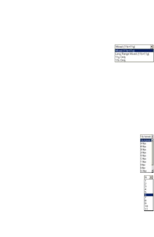
Wireless Mode: Set the communication mode
for the Wireless Barricade. (Default: Long
Range Mixed (11b+11g))
The Long Range Mixed (11b+11g) is an enhanced operation
mode. It provides a long range wireless connectivity of 328 feet
associated with the IEEE 802.11b standards by offering faster
speeds and longer distances from a wireless access point to a
wireless PC card.
g Nitro: The g Nitro implemented by Intersil’s Prism Nitro
technology dramatically enhances your wireless network speeds.
It provides up to 30% more throughput in an 11g only
environment, and improves network throughput by 3 times in
mixed mode. (Default: Enable)
Transmission Rate: As the wireless client moves further
away from the Wireless Barricade, then the wireless
data rate reduces. The transmit data rate from the
Wireless Barricade can be fixed or set to Auto.
(Default: Auto)
Channel: The wireless channel is set in the Wireless
Barricade. The wireless PCs will automatically scan the
wireless channels to detect and use the same channel as
the Wireless Barricade. (Default: 6)
Note: The available channel settings are limited by local
regulations.
Configuring the Wireless Barricade g Router
50
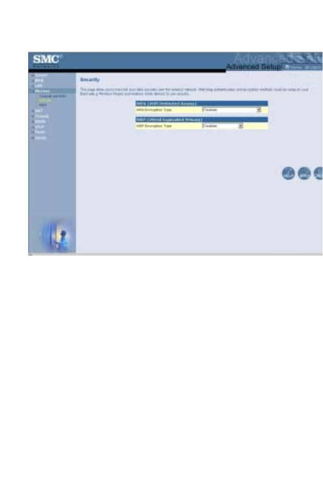
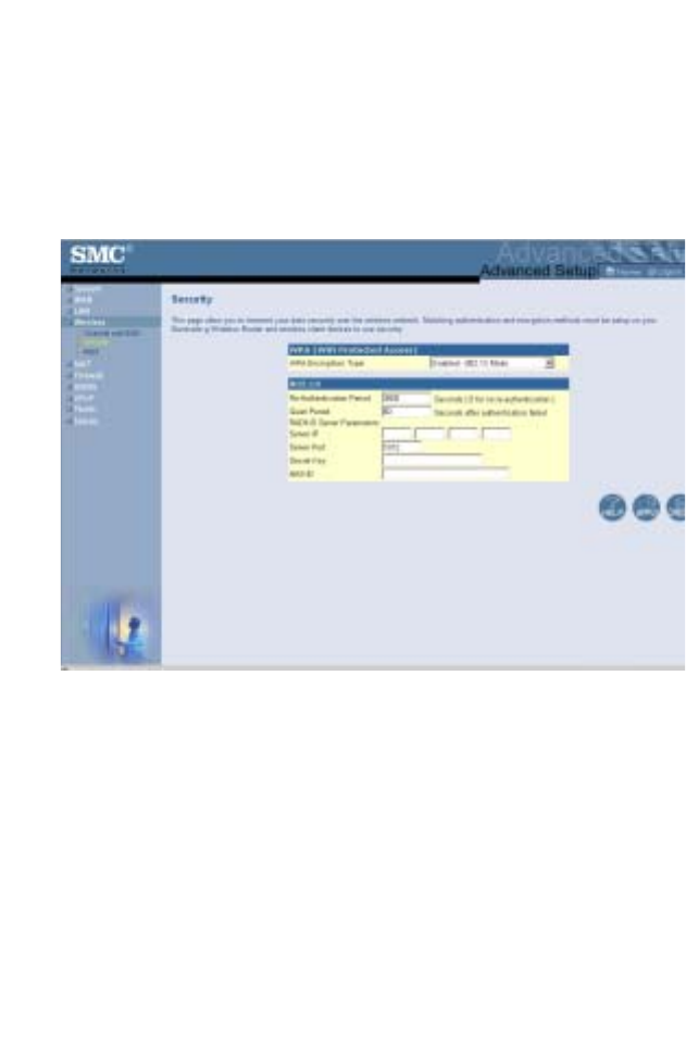
Security
If you are transmitting sensitive data across wireless channels,
you should enable Wi-Fi Protected Access (WPA) or Wired
Equivalent Privacy (WEP) encryption. Encryption security
requires you to use the same protocol set (WPA or WEP) and
encryption/decryption keys for the Wireless Barricade and all of
your wireless clients.
For a more secure network, the Wireless Barricade can
implement one of the following security mechanisms:
•Wi-Fi Protected Access (WPA) page 52
•Wired Equivalent Privacy (WEP) page 54

Advanced Setup
51
The security mechanisms that may be employed depend on the
level of security required, the network and management
resources available, and the software support provided on
wireless clients. A summary of wireless security considerations is
listed in the following table.
Security
Mechanism
Client
Support
Implementation Considerations
WEP Built-in support on all
802.11b and 802.11g
devices
• Provides only weak security
• Requires manual key management
WPA mode Requires WPA-enabled
system and network
card driver
(native support provided
in Windows XP)
• Provides good security in small
networks
• Requires configured RADIUS server,
or manual management of pre-shared
key
802.1x mode
Requires WPA-enabled
system and network
card driver
(native support provided
in Windows XP)
• Provides robust security in WPA-only
mode (i.e., WPA clients only)
• Requires configured RADIUS server
• 802.1x Extensible Authentication
Protocol (EAP) type may require
management of digital certificates for
clients and server
Configuring the Wireless Barricade g Router
52
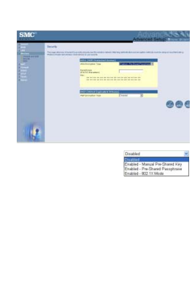
WPA Encryption Type
WPA is a stronger wireless security
solution than WEP. It uses a
combination of authentication and
broadcast/session keys.
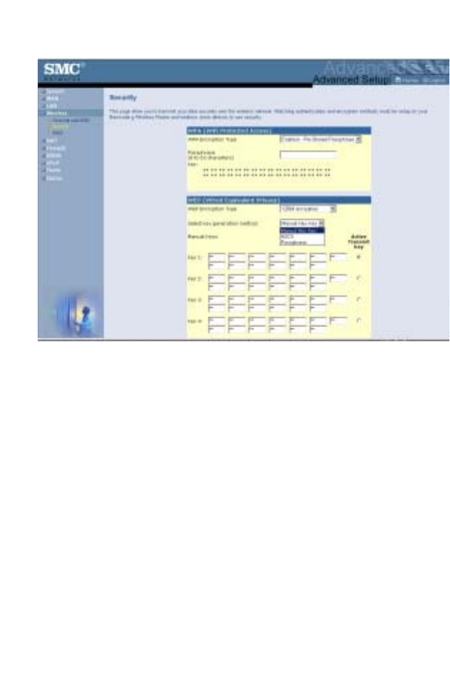
•Pre-Shared Key/Passphrase
If there is no authentication server on your SOHO network, you
can issue the Pre-Shared Key to the clients that connect to the
Wireless Barricade. Be sure to use the same key for the Wireless
Barricade and the connected clients.
Notes: 1. Manual Pre-Shared Key supports up to 64-Hex
characters.
2. Type 8~63 Hex characters for the Pre-Shared
Passphrase.
Advanced Setup
53
3. Do not use a key that is long and complex for your
clients to type accurately, as you might forget it.
4. A Hex (hexadecimal) digit is a number or letter in the
range 0-9 or A-F.
•802.1X Mode
The Wireless Barricade allows you to use 802.1x authentication
for an enterprise network environment with a RADIUS server
installed. In 802.1x mode, access will be checked against the
authentication database stored on the Wireless Barricade. You
must specify the authentication period, and the corresponding
parameters in the RADIUS Server Parameters field for the
remote authentication protocol.
Configuring the Wireless Barricade g Router
54
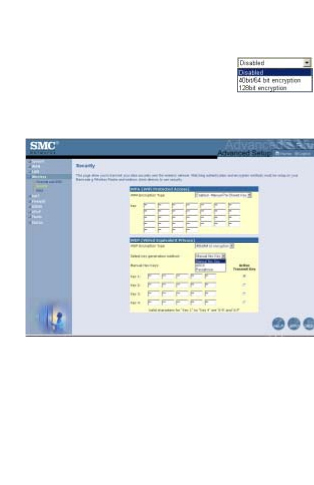
WEP Encryption Type
You can choose between standard 40/64-bit
or the more robust 128-bit encryption. To
manually configure the keys, select the WEP
Encryption Type option from the drop down
menu. For 40/64-bit encryption enter 5 hexadecimal pairs for
each key. For 128-bit encryption enter 13 hexadecimal pairs for
each key.
Advanced Setup
55
To generate the keys automatically, select the Passphrase option
from the drop down menu. For 40/64-bit encryption, 4 keys will
be generated. For 128-bit encryption, 1 key is generated and
repeated for the 4 keys.
The Active Transmit Key determines which key is used to encrypt
the transmit data. SMC recommend that you change the Active
Transmit key at regular intervals to maintain the security of your
wireless network.
Note: Active ASCII Keys must be exactly 5 characters for 40/
64-bit WEP.
Active ASCII Keys must be exactly 13 characters for
128-bit WEP.
If you use encryption, configure the same keys used for the
Wireless Barricade on each of your wireless clients. Note that
Wired Equivalent Privacy (WEP) protects data transmitted
between wireless nodes, but does not protect any transmissions
over your wired network or over the Internet.
Configuring the Wireless Barricade g Router
56
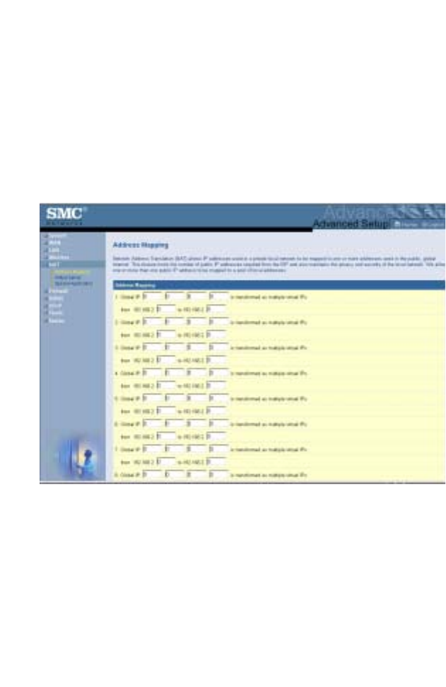
NAT - Network Address Translation
From this section you can configure the Address Mapping, Virtual
Server, and Special Application features that provide control over
the TCP/UDP port openings in the router’s firewall. This section
can be used to support several Internet based applications such
as web, email, FTP, and Telnet.
Address Mapping
Allows one or more public IP addresses to be shared by multiple
internal users. Enter the Public IP address you wish to share into
the Global IP field. Enter a range of internal IPs that will share the
global IP.
Advanced Setup
57
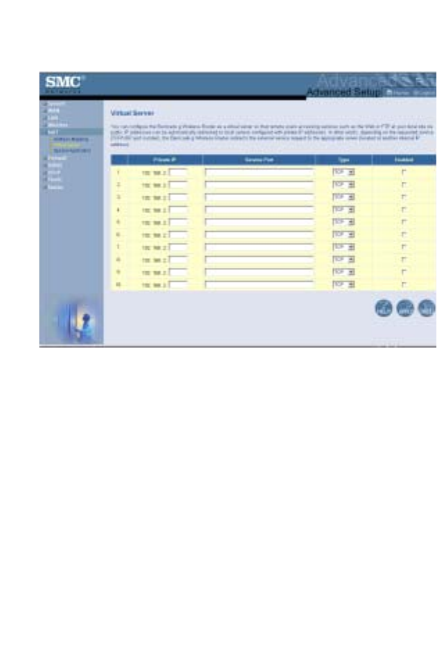
Virtual Server
If you configure the Wireless Barricade as a virtual server,
remote users accessing services such as web or FTP at your
local site via public IP addresses can be automatically redirected
to local servers configured with private IP addresses. In other
words, depending on the requested service (TCP/UDP port
number), the Wireless Barricade redirects the external service
request to the appropriate server (located at another internal IP
address).
For example, if you set Type/Public Port to TCP/80 (HTTP or
web) and the Private IP/Port to 192.168.2.2/80, then all HTTP
requests from outside users will be transferred to 192.168.2.2 on
port 80. Therefore, by just entering the IP address provided by
the ISP, Internet users can access the service they need at the
local address to which you redirect them.
The more common TCP service ports include:
HTTP: 80, FTP: 21, Telnet: 23, and POP3: 110
Configuring the Wireless Barricade g Router
58
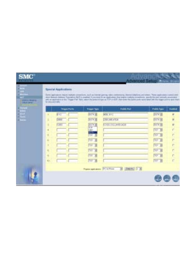
Special Applications
Some applications, such as Internet gaming, videoconferencing,
Internet telephony and others, require multiple connections.
These applications cannot work with Network Address
Translation (NAT) enabled. If you need to run applications that
require multiple connections, use the following screen to specify
the additional public ports to be opened for each application.
Specify the public port number normally associated with an
application in the Trigger Port field. Set the protocol type to TCP
or UDP, then enter the ports that the application requires.
Advanced Setup
59
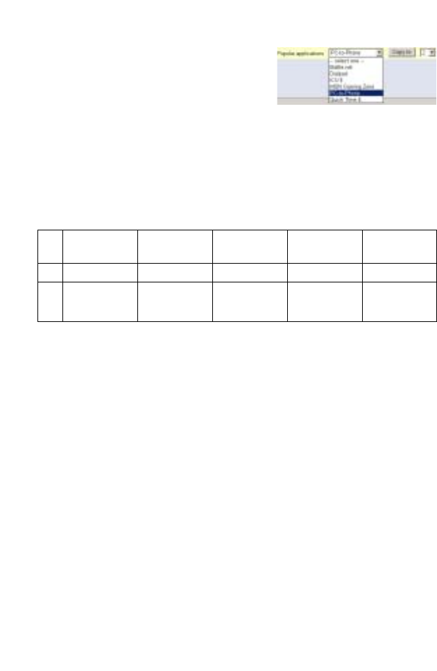
Popular applications requiring
multiple ports are listed in the
Popular Applications field. From the
drop-down list, choose the
application and then choose a row
number to copy this data into.
Note: Choosing a row that already contains data will
overwrite the current settings.
Example:
For a full list of ports and the services that run on them, see
www.iana.org/assignments/port-numbers.
ID Trigger
Port
Trigger
Type
Public Port Public Type Comment
1 6112 UDP 6112 UDP Battle.net
2 28800 TCP 2300-2400,
47624
TCP MSN Game
Zone
Configuring the Wireless Barricade g Router
60
Firewall
The Wireless Barricade firewall can provide access control of
connected client PCs, block common hacker attacks, including IP
Spoofing, Land Attack, Ping of Death, IP with zero length, Smurf
Attack, UDP port loopback, Snork Attack, TCP null scan, and
TCP SYN flooding. The firewall does not significantly affect
system performance, so we advise enabling it to protect your
network users.
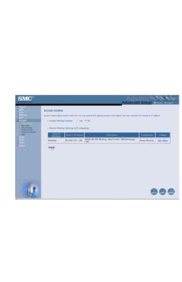
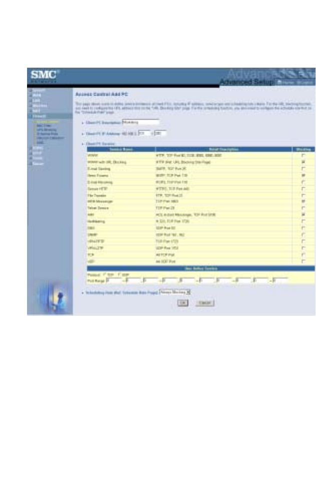
Access Control
Using this option allows you to specify different privileges based
on IP address for the client PCs.
Advanced Setup
61
Note: Click on Add PC and define the appropriate settings for
client PC services (as shown in the following screen).
Configuring the Wireless Barricade g Router
62
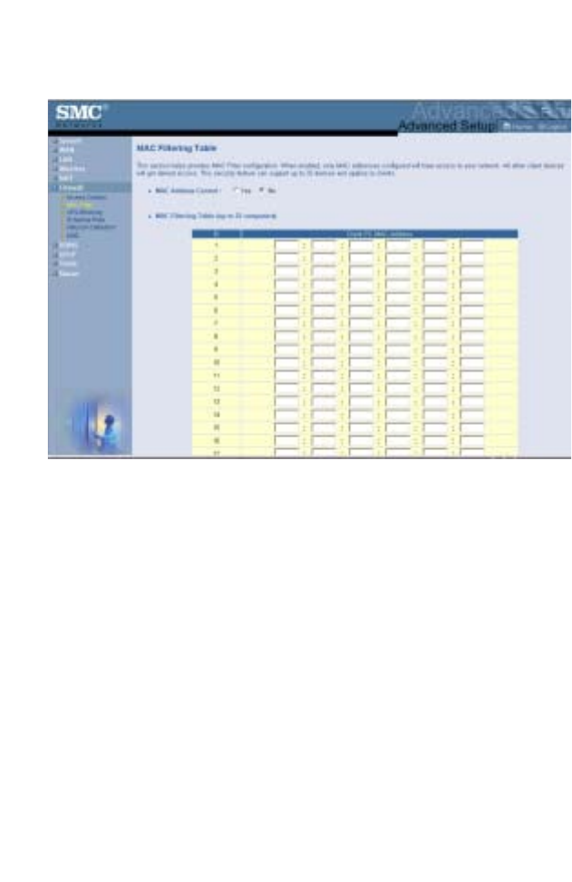
MAC Filtering Table
The MAC Filtering feature of the Wireless Barricade allows you to
control access to your network for up to 32 clients based on the
MAC (Media Access Control) address of the client machine. This
ID is unique to each network adapter. If the MAC address is
listed in the table, that client machine will have access to the
network.
Advanced Setup
63
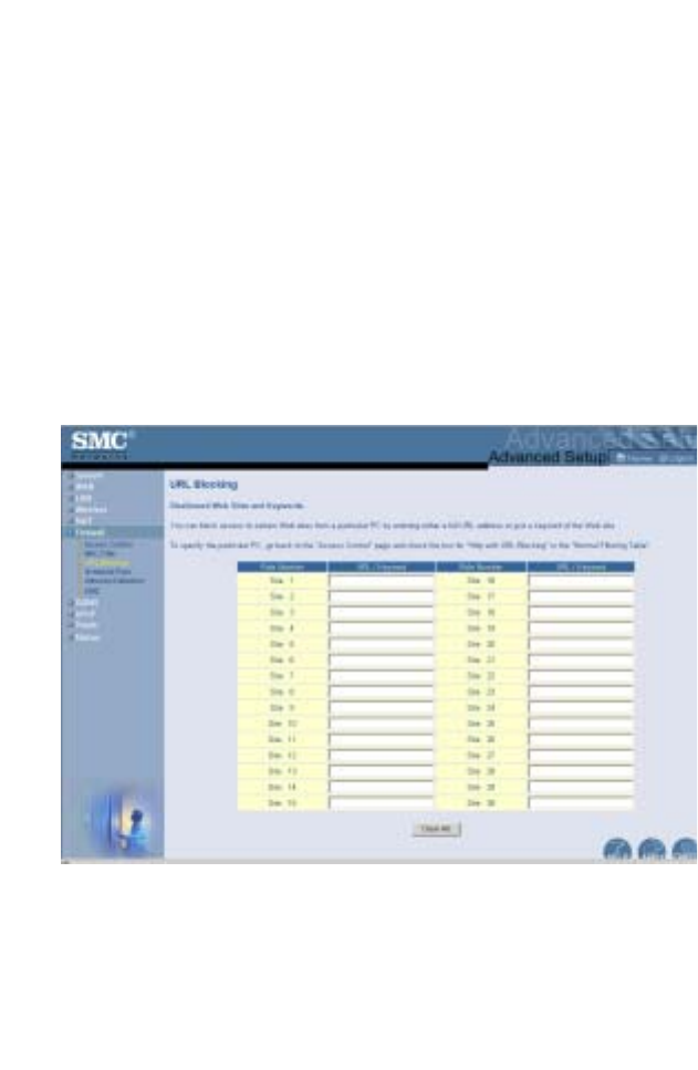
URL Blocking
To configure the URL Blocking feature, use the table below to
specify the web sites (e.g. www.somesite.com) and/or keywords
you want to filter on your network.
To complete this configuration, you will need to create or modify
an access rule in “Access Control” on page 60. To modify an
existing rule, click the Edit option next to the rule you want to
modify. To create a new rule, click on the Add PC option.
From the Access Control Add PC section check the option for
“WWW with URL Blocking” in the Client PC Service table to filter
out the web sites and keywords specified below.
Use the above screen to block access to web sites or to web
URLs containing the keywords specified in the keyword table.
Configuring the Wireless Barricade g Router
64
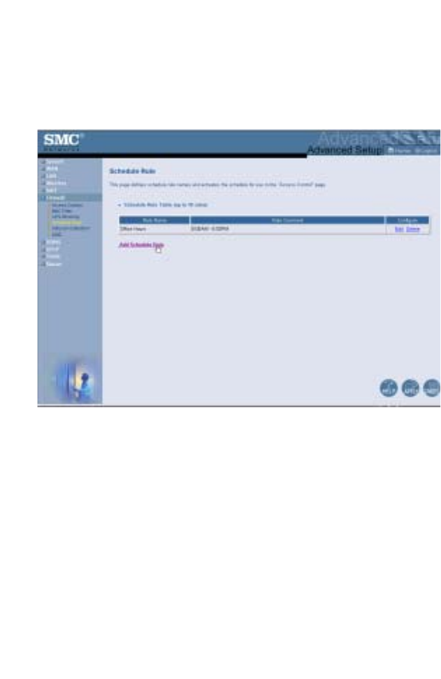
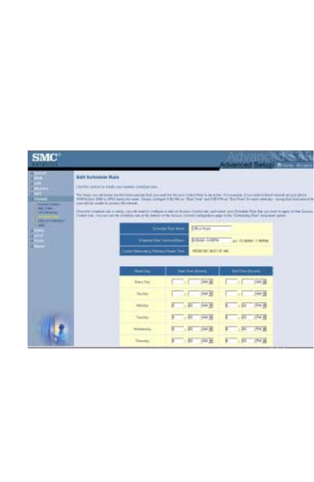
Schedule Rule
The Schedule Rule feature allows you to configure specific rules
based on time and date. These rules can then be used to
configure more specific access control.
Advanced Setup
65
Enable schedule-based Internet access control.
1. Click Add Schedule Rule.
2. Define the settings for the schedule rule (as shown on the
following screen).
3. Click OK and then click the APPLY button to save your
settings.
Configuring the Wireless Barricade g Router
66
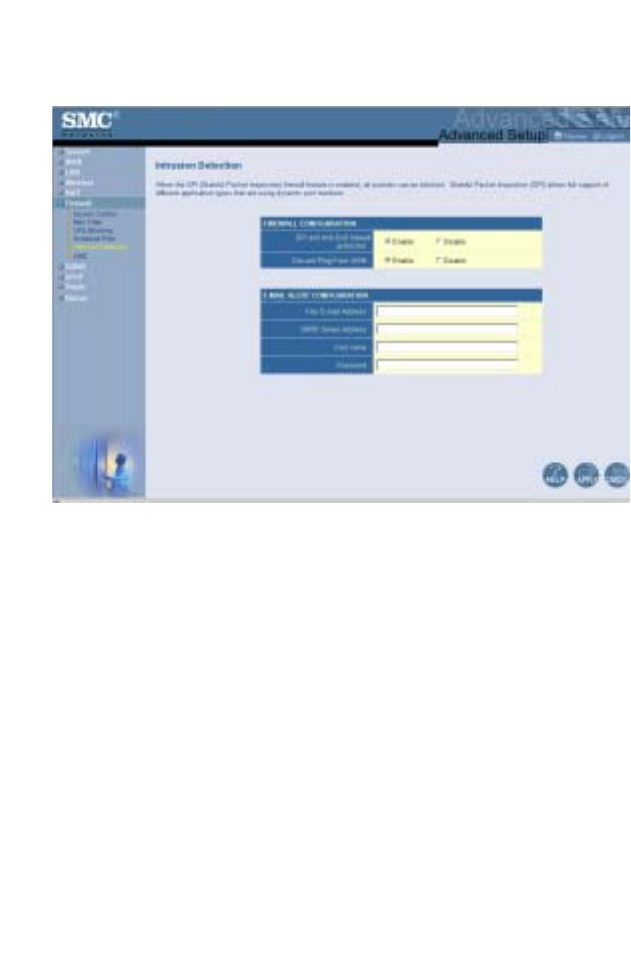
Intrusion Detection
• SPI and Anti-DoS (Denial-of-Service) firewall protection
(Default: Enable) – The Intrusion Detection Feature limits
access for incoming traffic at the WAN port. When the SPI
(Stateful Packet Inspection) feature is turned on, all incoming
packets will be inspected.
• Discard Ping from WAN (Default: Enable) – Prevents the
router from responding to any PING request on the WAN port.
• E-mail Alert Configuration – Enter your email address.
Specify your SMTP and POP3 servers, user name, and
password.
Advanced Setup
67
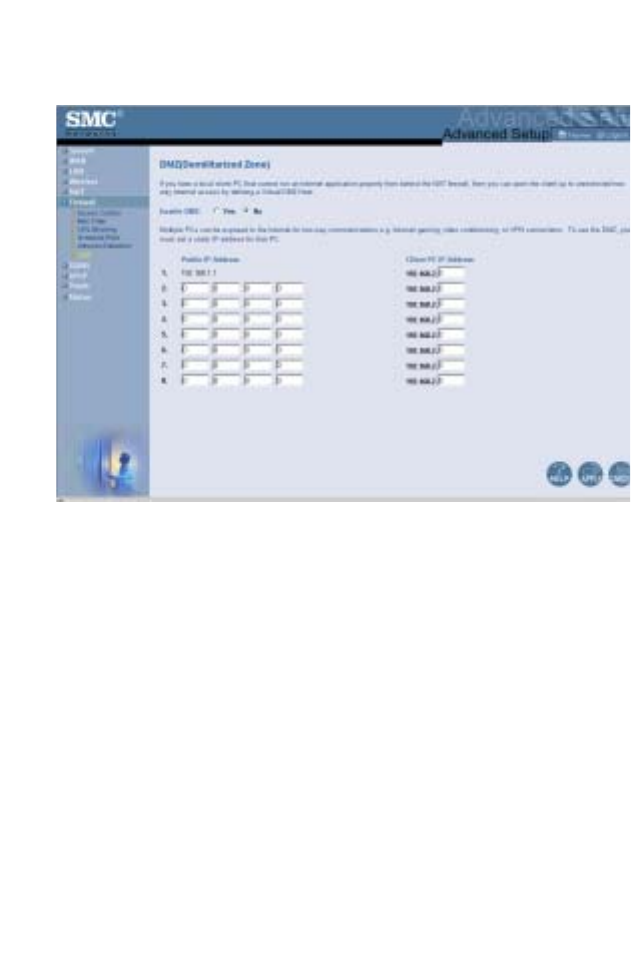
DMZ (Demilitarized Zone)
If you have a client PC that cannot run an Internet application
properly from behind the firewall, then you can open the client up
to unrestricted two-way Internet access. Enter the IP address of
a DMZ host to this screen. Adding a client to the DMZ may
expose your local network to a variety of security risks, so only
use this option as a last resort.
Configuring the Wireless Barricade g Router
68
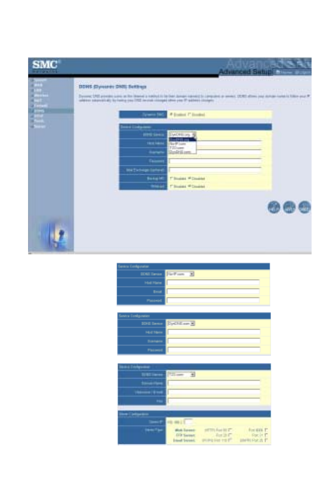
DDNS (Dynamic DNS) Settings
Advanced Setup
69
Dynamic DNS (DDNS) provides users on the Internet with a
method to tie their domain name to the router or server. DDNS
allows your domain name to follow your IP address automatically
by having your DNS records changed when your IP address
changes. (Default: Disabled)
The DDNS service dynamically updates DNS information to a
static hostname, provided by the DDNS service provider, as
clients’ IP addresses change.
Note: Please visit the web sites of the DDNS providers for
details.
For using DDNS, click on the enable radio button, select the
DDNS Service type, and then enter the user name, pass key
(password), host name or server IP, and email address.
Mail Exchanger (MX) and Backup MX provides you with flexible
email configurations. It allows you to control the delivery of your
mail for a specified domain or a subdomain. The Wildcard keeps
your hostname pointing to your IP address.
The TZO.com powered DNS allows you to host your own web
site, email server, FTP site, and more at your own location even
if you have a dynamic IP address. The Server Configuration
section automatically opens the port options checked in the
Virtual Server section.
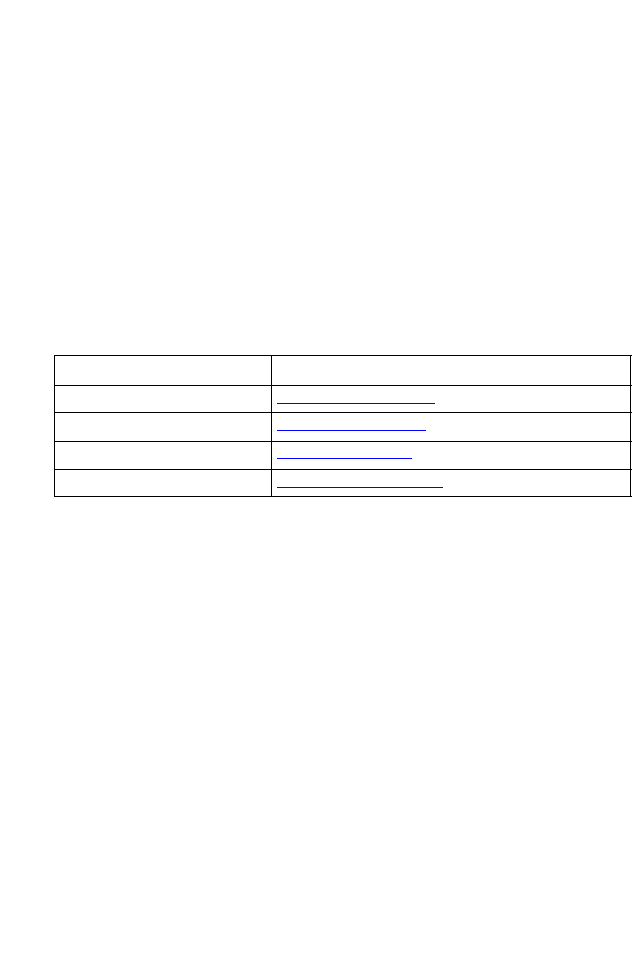
DDNS Service Provider Web Site
DynDNS.org http://www.dyndns.org
No-IP.com http://www.no-ip.com
TZO.com http://www.tzo.com
DYNDNS.COM http://www.dyndns.com
Configuring the Wireless Barricade g Router
70
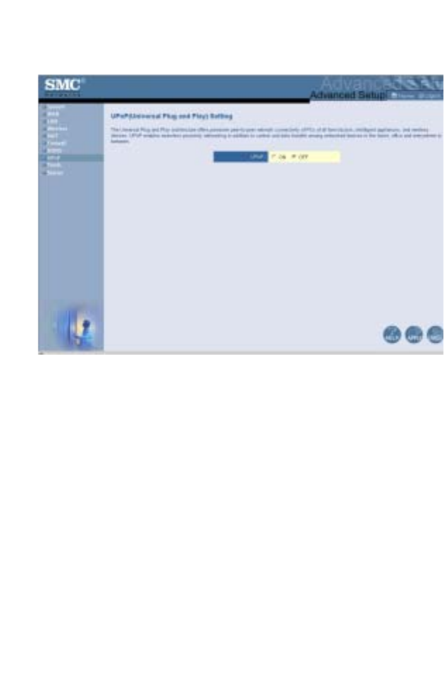
UPnP (Universal Plug and Play) Setting
Enable UPnP by checking ON in the screen above. UPnP allows
the device to automatically:
•dynamically join local network
•obtain an IP address
•convey its capabilities and learn about the presence and
capabilities of other devices.
•dynamically open ports for UPnP aware software, such as
MSN messenger advanced features (voice, remote control).
Advanced Setup
71
Tools
Use the Tools menu to back up the current configuration, restore
a previously saved configuration, restore factory settings, update
firmware, and reset the Wireless Barricade.
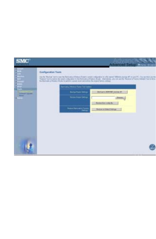
Tools - Configuration Tools
•Backup Router Settings – Saves the Wireless Barricade’s
configuration to a file.
•Restore Router Settings – Restores settings from a saved
backup configuration file.
1. Select the saved file by clicking on the browse button
2. Click the “Restore from config file.”
•Restore to factory defaults – Restores the Wireless Barricade
settings back to the factory defaults.
Configuring the Wireless Barricade g Router
72
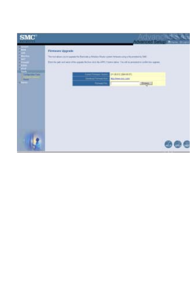
Tools - Firmware Upgrade
Use this screen to update the firmware or user interface to the
latest versions. Download the upgrade file from the SMC web
site (www.smc.com) and save it to your hard drive. In the
Firmware File field, click Browse to look for the downloaded file.
Click APPLY. Check the Status page Information section to
confirm that the upgrade process was successful.
Advanced Setup
73
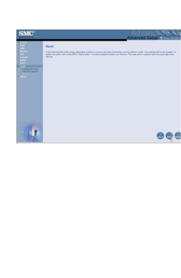
Tools - Reset
Click APPLY to reset the Wireless Barricade. The reset will be
complete when the power LED stops blinking.
Note: If you use the Reset button on the rear panel, the
Wireless Barricade performs a power reset. If the
button is depressed for over five seconds, all the LEDs
will illuminate and the factory settings will be restored.
Configuring the Wireless Barricade g Router
74
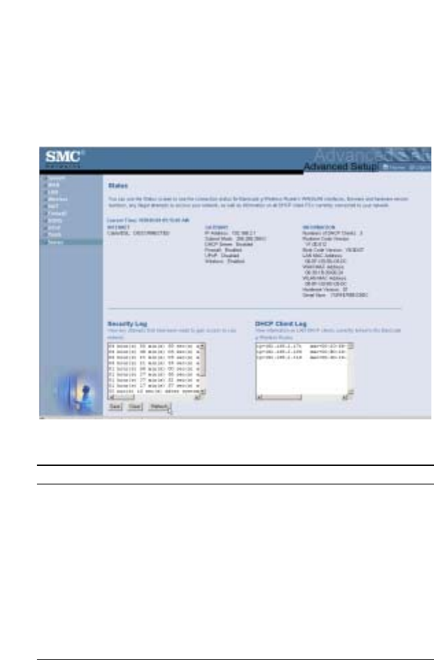
Status
The Status screen displays WAN/LAN connection status,
firmware, and hardware version numbers, illegal attempts to
access your network, as well as information on DHCP clients
connected to your network.
The following items are included on this screen:
Section Description
INTERNET Displays WAN connection type and status.
GATEWAY Displays system IP settings, as well as DHCP and Firewall
status.
INFORMATION Displays the number of attached clients, the firmware
versions, the physical MAC address for each media interface,
as well as the hardware version and serial number.
Security Log Displays illegal attempts to access your network.
Save Click on this button to save the security log file.
Clear Click on this button to delete the access log.
Refresh Click on this button to refresh the screen.
DHCP Client Log Displays information on all DHCP clients on your network.

75
TROUBLESHOOTING
The information outlined in this section describes some useful
steps for getting your computer and the Wireless Barricade
online.
A. Verify your connection to the Wireless Barricade.
If you are unable to access the Wireless Barricade’s web-based
administration pages, then you may not be properly connected or
configured. The screen shots in this section were taken on a
Windows 2000 machine, but the same steps will apply to
Windows 95/98/Me/XP.
To determine your TCP/IP configuration status please follow the
steps below:
1. Click Start then choose Run.
2. Type cmd or command to open a DOS prompt.
3. In the DOS window, type ipconfig and verify the information
that is displayed.
4. If your computer is set up for DHCP, then your TCP/IP
configuration should be similar to the information displayed:
•IP Address: 192.168.2.x (x is number between 100 and
199 by default.)
•Subnet: 255.255.255.0
•Gateway: 192.168.2.1
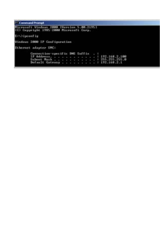
Troubleshooting
76
If you have an IP address that starts with 169.254.xxx.xxx then
see the next section.
If you have another IP address configured, then see section C.
B. I am getting an IP Address that starts with
169.254.xxx.xxx
If you are getting this IP address, then you need to check that
you are properly connected to the Wireless Barricade.
Confirm that you have a good link light on the Wireless Barricade
for the port to which this computer is connected. If not, please try
another cable.
If you have a good link light, please open up a DOS window as
described in the previous section and type ipconfig/renew.
If you are still unable to get an IP address from the Wireless
Barricade, please try rebooting your PC.
C. I have another IP Address displayed.
If you have another IP address listed, then the PC may not be
configured for a DHCP connection. Please refer to “Configuring
Client TCP/IP” on page 11 for information.
Once you have confirmed that your computer is configured for
DHCP, then please follow the steps below.
1. Open a DOS window as described above.
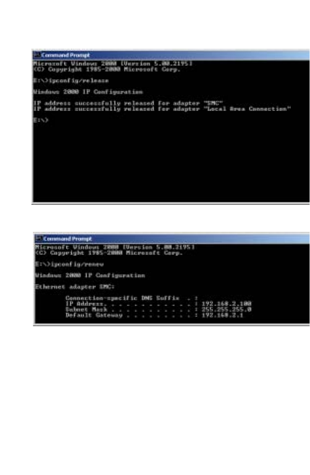
Troubleshooting
77
2. Type ipconfig/release.
3. Then type ipconfig/renew.
D. The 10/100 LED does not light after a connection is
made.
1. Check that the host computer and the Wireless Barricade are
both powered on.
2. Be sure the network cable is connected to both devices.
3. Verify that Category 5 cable is used if you are operating at
100 Mbps, and that the length of any cable does not exceed
100 m (328 ft).

Troubleshooting
78
4. Check the network card connections.
5. The 10BASE-T/100BASE-TX port, network card, or cable
may be defective.
E. If wireless clients cannot access the network, check the
following:
1. Be sure the Wireless Barricade and the wireless clients are
configured with the same Service Set ID (SSID).
2. If authentication or encryption are enabled, ensure that the
wireless clients are properly configured with the appropriate
authentication or encryption keys.
3. If authentication is being performed through a RADIUS
server, ensure that the clients are properly configured on the
RADIUS server.
4. If authentication is being performed through IEEE 802.1x, be
sure the wireless users have installed and properly configured
802.1x client software.
5. If MAC address filtering is enabled, be sure the client’s
address is included in the local filtering database.
6. If the wireless clients are roaming between Wireless
Barricade, make sure that all the access points and wireless
devices in the Extended Service Set (ESS) are configured to
the same SSID, and authentication method.

Troubleshooting
79
F. If you forgot or lost the password:
Set the Wireless Barricade to its default configuration by pressing
the reset button on the back panel for 10 seconds or more. There
is no password by default.
G. If all other recovery measures fail, and the Wireless
Barricade is still not functioning properly, take any of
these steps:
1. Reset the Wireless Barricade’s hardware using the web
interface, or through a power reset.
2. Reset the Wireless Barricade to its default configuration by
pressing the reset button on the back panel for 10 seconds or
more. Then click LOGIN to access the management interface.

Troubleshooting
80
Maximum Distance Table
Important Notice
Maximum distances posted below are actual tested distance
thresholds. However, there are many variables such as barrier
composition and construction and local environmental interference
that may impact your actual distances and cause you to
experience distance thresholds far lower than those posted below.
Notes: 1. Outdoor Environment: A line-of-sight environment with
no interference or obstruction between the Wireless
Barricade and clients.
2. Indoor Environment: A typical office or home
environment with floor to ceiling obstructions between
the Wireless Barricade and clients.
802.11b Wireless Distance Table
Speed and Distance Ranges
Environment 11 Mbps 5.5 Mbps 2 Mbps 1 Mbps
Outdoors1300 m
984 ft 465 m
1525 ft 500 m
1639 ft 515 m
1689 ft
Indoors260 m
197 ft 70 m
230 ft 83 m
272 ft 85 m
279 ft
802.11g Wireless Distance Table
Speed and Distance Ranges
Environment 54
Mbps 48
Mbps 36
Mbps 24
Mbps 18
Mbps 12
Mbps 11
Mbps 9
Mbps 6
Mbps 5
Mbps 2
Mbps 1
Mbps
Outdoors182 m
269 ft 100 m
328 ft 300 m
984 ft 330 m
1082 ft 350 m
1148 ft 450 m
1475 ft 470 m
1541 ft 485 m
1590 ft 495 m
1623 ft 510 m
1672 ft 520 m
1705 ft 525 m
1722 ft
Indoors220 m
66 ft 25 m
82 ft 35 m
115 ft 43 m
141 ft 50 m
164 ft 57 m
187 ft 66 m
216 ft 71 m
233 ft 80 m
262 ft 85 m
279 ft 90 m
295 ft 93 m
305 ft

81
SPECIFICATIONS
Below is an outline of the technical specifications for the
SMCWBR14-G.
Standards
IEEE 802.3 10BASE-T Ethernet
IEEE 802.3u 100BASE-TX FastEthernet
IEEE 802.11b
IEEE 802.11g
WAN Interface
10BASE-T/100BASE-TX
LAN Interfaces
10BASE-T/100BASE-TX
4 RJ-45 ports: LAN data transfer rate is up to 10/20 Mbps
(10BASE-T half/full duplex) or 100/200 Mbps (100BASE-TX
half/full duplex)
Data Rates
1/2/5.5/6/9/11/12/18/24/36/48/54 Mbps
Supports “Nitro Lite” turbo mode (data rate upto 140Mbps)
Frequency Band
IEEE 802.11b/g Radio: 2.4 GHz
USA - FCC 2412~2462MHz (Ch1~Ch11)
Canada - IC2412~2462MHz (Ch1~Ch11)
Europe - ETSI 2412~2472MHz (Ch1~Ch13)
Japan - STD-T66/STD-332412~2484MHz (Ch1~Ch14)
Modulation Type
OFDM, CCK

Specifications
82
Operating Channels
IEEE 802.11b/g compliant
11 channels (US, Canada)
13 channels (ETSI)
14 channels (Japan)
Antenna
Antenna Type
1 Dipole antenna with RP-SMA connector
Antenna Gain
1.43 dBi
Sensitivity Modulation Rate
Modulation Rate Receive Sensitivity Typical (dBm)
802.11b - 1Mbps -90
802.11b - 2Mbps -88
802.11b - 5.5Mbps -85
802.11b- 11Mbps -82
802.11g - 6Mbps -88
802.11g - 9Mbps -87
802.11g - 12Mbps -84
802.11g - 18Mbps -82
802.11g - 24Mbps -79
802.11g - 36Mbps -75
802.11g - 48Mbps -68
802.11g - 54Mbps -68

Specifications
83
RF Output Power
Management
Browser-based management
Both DHCP Server and Client provided
Advanced Features
Dynamic IP Address Configuration – DHCP, DNS
Wireless Security – 64/128-bit WEP/TKIP/AES-CCM/AES-OCB/
802.1x, WDS, SSID broadcast disabled, MAC address filtering
11g Nitro mode
Firewall – Access control, hacker prevention, logging
Virtual Server via NAT & NAPT
Virtual Private Network – PPTP, L2TP, IPSec pass-through
Intrusion Detection, email Alerts, Parental Control
Modulation Rate Output Power (dBm)
802.11b - 1Mbps 16
802.11b - 2Mbps 16
802.11b - 5.5Mbps 16
802.11b- 11Mbps 16
802.11g - 6Mbps 15
802.11g - 9Mbps 15
802.11g - 12Mbps 15
802.11g - 18Mbps 15
802.11g - 24Mbps 15
802.11g - 36Mbps 15
802.11g - 48Mbps 12
802.11g - 54Mbps 12

Specifications
84
Indicator Panel
Power, WLAN, WAN (Link, Activity), LAN (Link/Activity,
Speed - 10/100 Mbps)
Dimensions
155 x 130 x 26 mm (6.10 x 5.12 x 1.02 in.)
Weight
410 g (14.46 oz)
Input Power
9 VDC, 1 A
DVE
US: DV-91A
EU: DV-91AUP
Power Consumption
5 Watts max. @ 100-240 VAC
Internet Standards
RFC 826 ARP, RFC 791 IP, RFC 792 ICMP, RFC 768 UDP, RFC
793 TCP, RFC 854-859 TELNET, RFC 1321 MD5, RFC 1497
BOOTP Extension, RFC 1570 PPP LCP Extension, RFC 1631
NAT, RFC1661 PPP, RFC 1700 Assigned Numbers, RFC 1866
HTML, RFC 1945 HTTP, RFC 1994 CHAP, RFC 2131 DHCP,
RFC 2637 PPTP
Temperature
Operating 0 to 40 °C (32 to 104 °F)
Storage -40 to 70 °C (-40 to 158 °F)
Humidity
5% to 95% (non-condensing)

Specifications
85
Compliances
CE Mark
Emissions
FCC Class B
VCCI Class B
Industry Canada Class B
EN55022 (CISPR 22) Class B
C-Tick - AS/NZS 3548 (1995) Class B
Immunity
EN 61000-3-2/3
EN 61000-4-2/3/4/5/6/8/11
DGT LP0002: 2004
Safety
CSA/NRTL (UL1950, CSA 22.2.950)
GS (EN60950)
CB (IEC60950)

Specifications
86