Arcadyan Technology WG4005E1 BARRICADE TM g 108Mbps WIRELESS BROADBAND ROUTER User Manual 00
Arcadyan Technology Corporation BARRICADE TM g 108Mbps WIRELESS BROADBAND ROUTER 00
USERS MANUAL


38 Tesla
Irvine, CA 92618
Phone: (949) 679-8000
Wireless Broadband Router
User’s Guide
From SMC’s line of
award-winning connectivity solutions
April 2006
R02 F/W 2.0
149100019300J

Information furnished is believed to be accurate and reliable. However, no responsibility is assumed by our
company for its use, nor for any infringements of patents or other rights of third parties which may result
from its use. No license is granted by implication or otherwise under any patent or patent rights of our
company. We reserve the right to change specifications at any time without notice.
Copyright © 2006 by
SMC Networks, Inc.
38 Tesla
Irvine, CA 92618
All rights reserved.
Trademarks:
Product and company names are trademarks or registered trademarks of their respective holders.

i
L
IMITED
W
ARRANTY
Limited Warranty Statement: SMC Networks, Inc. (“SMC”) warrants its products to be
free from defects in workmanship and materials, under normal use and service, for the
applicable warranty term. All SMC products carry a standard 90-day limited warranty from
the date of purchase from SMC or its Authorized Reseller. SMC may, at its own discretion,
repair or replace any product not operating as warranted with a similar or functionally
equivalent product, during the applicable warranty term. SMC will endeavor to repair or
replace any product returned under warranty within 30 days of receipt of the product.
The standard limited warranty can be upgraded to a Limited Lifetime* warranty by registering
new products within 30 days of purchase from SMC or its Authorized Reseller. Registration
can be accomplished via the enclosed product registration card or online via the SMC web
site. Failure to register will not affect the standard limited warranty. The Limited Lifetime
warranty covers a product during the Life of that Product, which is defined as the period of
time during which the product is an “Active” SMC product. A product is considered to be
“Active” while it is listed on the current SMC price list. As new technologies emerge, older
technologies become obsolete and SMC will, at its discretion, replace an older product in its
product line with one that incorporates these newer technologies. At that point, the obsolete
product is discontinued and is no longer an “Active” SMC product. A list of discontinued
products with their respective dates of discontinuance can be found at:
http://www.smc.com/index.cfm?action=customer_service_warranty.
All products that are replaced become the property of SMC. Replacement products may be
either new or reconditioned. Any replaced or repaired product carries either a 30-day limited
warranty or the remainder of the initial warranty, whichever is longer. SMC is not responsible
for any custom software or firmware, configuration information, or memory data of
Customer contained in, stored on, or integrated with any products returned to SMC pursuant
to any warranty. Products returned to SMC should have any customer-installed accessory or
add-on components, such as expansion modules, removed prior to returning the product for
replacement. SMC is not responsible for these items if they are returned with the product.
Customers must contact SMC for a Return Material Authorization number prior to returning
any product to SMC. Proof of purchase may be required. Any product returned to SMC
without a valid Return Material Authorization (RMA) number clearly marked on the outside
of the package will be returned to customer at customer’s expense. For warranty claims within
North America, please call our toll-free customer support number at (800) 762-4968.
Customers are responsible for all shipping charges from their facility to SMC. SMC is
responsible for return shipping charges from SMC to customer.

L
IMITED
W
ARRANTY
ii
WARRANTIES EXCLUSIVE: IF AN SMC PRODUCT DOES NOT OPERATE AS
WARRANTED ABOVE, CUSTOMER’S SOLE REMEDY SHALL BE REPAIR OR
REPLACEMENT OF THE PRODUCT IN QUESTION, AT SMC’S OPTION. THE
FOREGOING WARRANTIES AND REMEDIES ARE EXCLUSIVE AND ARE IN
LIEU OF ALL OTHER WARRANTIES OR CONDITIONS, EXPRESS OR IMPLIED,
EITHER IN FACT OR BY OPERATION OF LAW, STATUTORY OR OTHERWISE,
INCLUDING WARRANTIES OR CONDITIONS OF MERCHANTABILITY AND
FITNESS FOR A PARTICULAR PURPOSE. SMC NEITHER ASSUMES NOR
AUTHORIZES ANY OTHER PERSON TO ASSUME FOR IT ANY OTHER
LIABILITY IN CONNECTION WITH THE SALE, INSTALLATION,
MAINTENANCE OR USE OF ITS PRODUCTS. SMC SHALL NOT BE LIABLE
UNDER THIS WARRANTY IF ITS TESTING AND EXAMINATION DISCLOSE THE
ALLEGED DEFECT IN THE PRODUCT DOES NOT EXIST OR WAS CAUSED BY
CUSTOMER’S OR ANY THIRD PERSON’S MISUSE, NEGLECT, IMPROPER
INSTALLATION OR TESTING, UNAUTHORIZED ATTEMPTS TO REPAIR, OR
ANY OTHER CAUSE BEYOND THE RANGE OF THE INTENDED USE, OR BY
ACCIDENT, FIRE, LIGHTNING, OR OTHER HAZARD.
LIMITATION OF LIABILITY: IN NO EVENT, WHETHER BASED IN CONTRACT
OR TORT (INCLUDING NEGLIGENCE), SHALL SMC BE LIABLE FOR
INCIDENTAL, CONSEQUENTIAL, INDIRECT, SPECIAL, OR PUNITIVE
DAMAGES OF ANY KIND, OR FOR LOSS OF REVENUE, LOSS OF BUSINESS, OR
OTHER FINANCIAL LOSS ARISING OUT OF OR IN CONNECTION WITH THE
SALE, INSTALLATION, MAINTENANCE, USE, PERFORMANCE, FAILURE, OR
INTERRUPTION OF ITS PRODUCTS, EVEN IF SMC OR ITS AUTHORIZED
RESELLER HAS BEEN ADVISED OF THE POSSIBILITY OF SUCH DAMAGES.
SOME STATES DO NOT ALLOW THE EXCLUSION OF IMPLIED WARRANTIES
OR THE LIMITATION OF INCIDENTAL OR CONSEQUENTIAL DAMAGES FOR
CONSUMER PRODUCTS, SO THE ABOVE LIMITATIONS AND EXCLUSIONS
MAY NOT APPLY TO YOU. THIS WARRANTY GIVES YOU SPECIFIC LEGAL
RIGHTS, WHICH MAY VARY FROM STATE TO STATE. NOTHING IN THIS
WARRANTY SHALL BE TAKEN TO AFFECT YOUR STATUTORY RIGHTS.
* SMC will provide warranty service for one year following discontinuance from the active
SMC price list. Under the limited lifetime warranty, internal and external power supplies, fans,
and cables are covered by a standard one-year warranty from date of purchase.
SMC Networks, Inc.
38 Tesla
Irvine, CA 92618

iii
C
OMPLIANCES
Federal Communication Commission Interference
Statement
This equipment has been tested and found to comply with the limits for a Class B digital
device, pursuant to Part 15 of the FCC Rules. These limits are designed to provide
reasonable protection against harmful interference in a residential installation. This
equipment generates, uses and can radiate radio frequency energy and, if not installed and
used in accordance with the instructions, may cause harmful interference to radio
communications. However, there is no guarantee that interference will not occur in a
particular installation. If this equipment does cause harmful interference to radio or
television reception, which can be determined by turning the equipment off and on, the user
is encouraged to try to correct the interference by one of the following measures:
• Reorient or relocate the receiving antenna.
• Increase the separation between the equipment and receiver.
• Connect the equipment into an outlet on a circuit different from that to which the receiver
is connected.
• Consult the dealer or an experienced radio/TV technician for help.
This device complies with Part 15 of the FCC Rules. Operation is subject to the following
two conditions: (1) This device may not cause harmful interference, and (2) this device must
accept any interference received, including interference that may cause undesired operation.
FCC Caution: Any changes or modifications not expressly approved by the party
responsible for compliance could void the user's authority to operate this equipment.
IMPORTANT NOTE:
FCC Radiation Exposure Statement:
This equipment complies with FCC radiation exposure limits set forth for an uncontrolled
environment. This equipment should be installed and operated with minimum distance 20 cm
between the radiator & your body.
This transmitter must not be co-located or operating in conjunction with any other antenna
or transmitter.
IEEE 802.11b or 802.11g operation of this product in the U.S.A. is firmware-limited to
channels 1 through 11.

C
OMPLIANCES
iv
Industry Canada Statement
Operation is subject to the following two conditions:
1. this device may not cause interference and
2. this device must accept any interference, including interference that may cause undesired
operation of the device
To prevent radio interference to the licensed service, this device is intended to be operated
indoors and away from windows to provide maximum shielding. Equipment (or its transmit
antenna) that is installed outdoors is subject to licensing.
This device has been designed to operate with an antenna having a maximum gain of 2.0 dBi.
Any antenna having a higher gain is strictly prohibited per regulations of Industry Canada.
The required antenna impedance is 50 ohms.
To reduce potential radio interference to other users, the antenna type and its gain should be
so chosen that the EIRP is not more than required for successful communication.
EC Declaration of Conformity
SMC contact for these products in Europe is:
SMC Networks Europe,
Edificio Conata II,
Calle Fructuos Gelabert 6-8, 2o, 4a,
08970 - Sant Joan Despi,
Barcelona, Spain.
Marking by the above symbol indicates compliance with the Essential Requirements of the
R&TTE Directive of the European Union (1999/5/EC). This equipment meets the
following conformance standards:
EN 300 328 V1.6.1 (11-2004)
EN 301 489-1 V1.4.1 (08-2002)
EN 301 489-17 V1.2.1 (08-2002)
EN 60950-1: 2001

C
OMPLIANCES
v
Countries of Operation & Conditions of Use in the
European Community
This device is intended to be operated in all countries of the European Community.
Requirements for indoor vs. outdoor operation, license requirements and allowed channels of
operation apply in some countries as described below:
Note: The user must use the configuration utility provided with this product to ensure the
channels of operation are in conformance with the spectrum usage rules for European
Community countries as described below.
• This device requires that the user or installer properly enter the current country of
operation in the command line interface as described in the user guide, before operating
this device.
• This device will automatically limit the allowable channels determined by the current
country of operation. Incorrectly entering the country of operation may result in illegal
operation and may cause harmful interference to other system. The user is obligated to
ensure the device is operating according to the channel limitations, indoor/outdoor
restrictions and license requirements for each European Community country as described
in this document.
• This device may be operated indoors or outdoors in all countries of the European Community
using the 2.4 GHz band: Channels 1 - 13.
Declaration of Conformity in Languages of the
European Community
English Hereby, SMC Networks, declares that this Radio LAN device is in
compliance with the essential requirements and other relevant provisions
of Directive 1999/5/EC.
Finnish Valmistaja SMC Networks vakuuttaa täten että Radio LAN device
tyyppinen laite on direktiivin 1999/5/EY oleellisten vaatimusten ja sitä
koskevien direktiivin muiden ehtojen mukainen.
Dutch Hierbij verklaart SMC Networks dat het toestel Radio LAN device in
overeenstemming is met de essentiële eisen en de andere relevante
bepalingen van richtlijn 1999/5/EG
Bij deze SMC Networks dat deze Radio LAN device voldoet aan de
essentiële eisen en aan de overige relevante bepalingen van Richtlijn 1999/
5/EC.
French Par la présente SMC Networks déclare que l'appareil Radio LAN device est
conforme aux exigences essentielles et aux autres dispositions pertinentes
de la directive 1999/5/CE
C
OMPLIANCES
vi
DGT Statement of Taiwan
經型式認證合格之低功率射頻電機,非經許可,公司、商號或使用者均不得擅自變
更頻率、加大功率或變更原設計之特性及功能。
低功率射頻電機之使用不得影響飛航安全及干擾合法通信;經發現有干擾現象時,
應立即停用,並改善至無干擾時方得繼續使用。前項合法通信,指依電信法規定作
業之無線電通信。低功率射頻電機須忍受合法通信或工業、科學及醫療用電波輻射
性電機設備之干擾。
Swedish Härmed intygar SMC Networks att denna Radio LAN device står I
överensstämmelse med de väsentliga egenskapskrav och övriga relevanta
bestämmelser som framgår av direktiv 1999/5/EG.
Danish Undertegnede SMC Networks erklærer herved, at følgende udstyr Radio
LAN device overholder de væsentlige krav og øvrige relevante krav i
direktiv 1999/5/EF
German Hiermit erklärt SMC Networks, dass sich dieser/diese/dieses Radio LAN
device in Übereinstimmung mit den grundlegenden Anforderungen und
den anderen relevanten Vorschriften der Richtlinie 1999/5/EG befindet".
(BMWi)
Hiermit erklärt SMC Networks die Übereinstimmung des Gerätes Radio
LAN device mit den grundlegenden Anforderungen und den anderen
relevanten Festlegungen der Richtlinie 1999/5/EG. (Wien)
Greek
Italian Con la presente SMC Networks dichiara che questo Radio LAN device è
conforme ai requisiti essenziali ed alle altre disposizioni pertinenti stabilite
dalla direttiva 1999/5/CE.
Spanish Por medio de la presente SMC Networks declara que el Radio LAN device
cumple con los requisitos esenciales y cualesquiera otras disposiciones
aplicables o exigibles de la Directiva 1999/5/CE
Portuguese SMC Networks declara que este Radio LAN device está conforme com os
requisitos essenciais e outras disposições da Directiva 1999/5/CE.

C
OMPLIANCES
vii
Safety Compliance
Underwriters Laboratories Compliance Statement
Important! Before making connections, make sure you have the correct cord set. Check it
(read the label on the cable) against the following:
The unit automatically matches the connected input voltage. Therefore, no additional
adjustments are necessary when connecting it to any input voltage within the range marked
on the power adapter.
Information for Power Source
This unit is to be used with a class 2 or level 3 external power adapter, approved suitable for
use in North American equipment installation, having an output voltage rating of 12 V DC,
and output current rating of 1.0 A or equivalent.
Operating Voltage Cord Set Specifications
120 Volts UL Listed/CSA Certified Cord Set
Minimum 18 AWG
Type SVT or SJT three conductor cord
Maximum length of 15 feet
Parallel blade, grounding type attachment plug rated 15
A, 125 V
240 Volts (Europe only) Cord Set with H05VV-F cord having three conductors
with minimum diameter of 0.75 mm2
IEC-320 receptacle
Male plug rated 10 A, 250 V
N11846

C
OMPLIANCES
viii
Wichtige Sicherheitshinweise (Germany)
1. Bitte lesen Sie diese Hinweise sorgfältig durch.
2. Heben Sie diese Anleitung für den späteren Gebrauch auf.
3. Vor jedem Reinigen ist das Gerät vom Stromnetz zu trennen. Verwenden Sie keine Flüs-
sigoder Aerosolreiniger. Am besten eignet sich ein angefeuchtetes Tuch zur Reinigung.
4. Die Netzanschlu ßsteckdose soll nahe dem Gerät angebracht und leicht zugänglich sein.
5. Das Gerät ist vor Feuchtigkeit zu schützen.
6. Bei der Aufstellung des Gerätes ist auf sicheren Stand zu achten. Ein Kippen oder
Fallen könnte Beschädigungen hervorrufen.
7. Die Belüftungsöffnungen dienen der Luftzirkulation, die das Gerät vor Überhitzung
schützt. Sorgen Sie dafür, daß diese Öffnungen nicht abgedeckt werden.
8. Beachten Sie beim Anschluß an das Stromnetz die Anschlußwerte.
9. Verlegen Sie die Netzanschlußleitung so, daß niemand darüber fallen kann. Es sollte
auch nichts auf der Leitung abgestellt werden.
10. Alle Hinweise und Warnungen, die sich am Gerät befinden, sind zu beachten.
11. Wird das Gerät über einen längeren Zeitraum nicht benutzt, sollten Sie es vom Strom-
netz trennen. Somit wird im Falle einer Überspannung eine Beschädigung vermieden.
12. Durch die Lüftungsöffnungen dürfen niemals Gegenstände oder Flüssigkeiten in das
Gerät gelangen. Dies könnte einen Brand bzw. elektrischen Schlag auslösen.
13. Öffnen sie niemals das Gerät. Das Gerät darf aus Gründen der elektrischen Sicherheit
nur von authorisiertem Servicepersonal geöffnet werden.
14. Wenn folgende Situationen auftreten ist das Gerät vom Stromnetz zu trennen und von
einer qualifizierten Servicestelle zu überprüfen:
a. Netzkabel oder Netzstecker sind beschädigt.
b. Flüssigkeit ist in das Gerät eingedrungen.
c. Das Gerät war Feuchtigkeit ausgesetzt.
d. Wenn das Gerät nicht der Bedienungsanleitung entsprechend funktioniert oder Sie mit
Hilfe dieser Anleitung keine Verbesserung erzielen.
e. Das Gerät ist gefallen und/oder das Gehäuse ist beschädigt.
f. Wenn das Gerät deutliche Anzeichen eines Defektes aufweist.
15. Stellen Sie sicher, daß die Stromversorgung dieses Gerätes nach der EN 60950 geprüft
ist. Ausgangswerte der Stromversorgung sollten die Werte von AC 7,5-8 V, 50-60 Hz
nicht über oder unterschreiten sowie den minimalen Strom von 1 A nicht unterschreiten.
Der arbeitsplatzbezogene Schalldruckpegel nach DIN 45 635 Teil 1000 beträgt 70 dB(A)
oder weniger.

ix
T
ABLE
OF
C
ONTENTS
1 Introduction . . . . . . . . . . . . . . . . . . . . . . . . . . . . . . . . . .1-1
About the BARRICADE . . . . . . . . . . . . . . . . . . . . . . . . . . . . . . . . . . . . . 1-1
Features and Benefits . . . . . . . . . . . . . . . . . . . . . . . . . . . . . . . . . . . . . . . . 1-2
Applications . . . . . . . . . . . . . . . . . . . . . . . . . . . . . . . . . . . . . . . . . . . . . . . 1-3
2 Installation . . . . . . . . . . . . . . . . . . . . . . . . . . . . . . . . . . 2-1
Package Contents . . . . . . . . . . . . . . . . . . . . . . . . . . . . . . . . . . . . . . . . . . . 2-1
System Requirements . . . . . . . . . . . . . . . . . . . . . . . . . . . . . . . . . . . . . . . . 2-2
Hardware Description . . . . . . . . . . . . . . . . . . . . . . . . . . . . . . . . . . . . . . . 2-2
ISP Settings . . . . . . . . . . . . . . . . . . . . . . . . . . . . . . . . . . . . . . . . . . . . . . . . 2-5
Connect the System . . . . . . . . . . . . . . . . . . . . . . . . . . . . . . . . . . . . . . . . . 2-5
Connect the ADSL/Cable Modem Line . . . . . . . . . . . . . . . . . . . 2-5
Phone Line Configuration . . . . . . . . . . . . . . . . . . . . . . . . . . . . . . 2-6
Connecting the BARRICADE to your LAN . . . . . . . . . . . . . . . 2-8
Connect the Power Adapter . . . . . . . . . . . . . . . . . . . . . . . . . . . . . 2-9
3 Configuring The Client PC . . . . . . . . . . . . . . . . . . . . . 3-1
TCP/IP Configuration . . . . . . . . . . . . . . . . . . . . . . . . . . . . . . . . . . . . . . . 3-2
Windows 2000 . . . . . . . . . . . . . . . . . . . . . . . . . . . . . . . . . . . . . . . 3-3
Obtain IP Settings From Your BARRICADE . . . . . . . . . . . . . . 3-5
Manual IP Configuration . . . . . . . . . . . . . . . . . . . . . . . . . . . . . . . 3-7
Windows XP . . . . . . . . . . . . . . . . . . . . . . . . . . . . . . . . . . . . . . . . . 3-9
Disable HTTP Proxy . . . . . . . . . . . . . . . . . . . . . . . . . . . . . . . . . 3-14
Configuring Your Macintosh Computer . . . . . . . . . . . . . . . . . . . . . . . . 3-15
Disable HTTP Proxy . . . . . . . . . . . . . . . . . . . . . . . . . . . . . . . . . 3-17
4 Configuring the BARRICADE . . . . . . . . . . . . . . . . . . 4-1
Navigating the Web Browser Interface . . . . . . . . . . . . . . . . . . . . . . . . . . 4-2
Making Configuration Changes . . . . . . . . . . . . . . . . . . . . . . . . . . 4-3
Login Screen . . . . . . . . . . . . . . . . . . . . . . . . . . . . . . . . . . . . . . . . . . . . . . . 4-4
Setup Wizard . . . . . . . . . . . . . . . . . . . . . . . . . . . . . . . . . . . . . . . . . . . . . . 4-5
Getting Started . . . . . . . . . . . . . . . . . . . . . . . . . . . . . . . . . . . . . . . 4-5
Wireless Settings . . . . . . . . . . . . . . . . . . . . . . . . . . . . . . . . . . . . . . 4-6
Internet Settings . . . . . . . . . . . . . . . . . . . . . . . . . . . . . . . . . . . . . . 4-9
Cable Modem Settings . . . . . . . . . . . . . . . . . . . . . . . . . . . . . . . . 4-10

T
ABLE
OF
C
ONTENTS
x
ADSL Settings - Fixed-IP xDSL . . . . . . . . . . . . . . . . . . . . . . . . 4-11
ADSL Settings - PPPoE . . . . . . . . . . . . . . . . . . . . . . . . . . . . . . . 4-12
ADSL Settings - PPTP . . . . . . . . . . . . . . . . . . . . . . . . . . . . . . . . 4-13
ADSL Settings - BigPond . . . . . . . . . . . . . . . . . . . . . . . . . . . . . . 4-14
Home Network Settings . . . . . . . . . . . . . . . . . . . . . . . . . . . . . . . . . . . . 4-15
Status . . . . . . . . . . . . . . . . . . . . . . . . . . . . . . . . . . . . . . . . . . . . . . 4-16
LAN Settings . . . . . . . . . . . . . . . . . . . . . . . . . . . . . . . . . . . . . . . 4-19
WAN Settings . . . . . . . . . . . . . . . . . . . . . . . . . . . . . . . . . . . . . . . 4-21
Dynamic IP . . . . . . . . . . . . . . . . . . . . . . . . . . . . . . . . . . . . . . . . . 4-22
PPPoE . . . . . . . . . . . . . . . . . . . . . . . . . . . . . . . . . . . . . . . . . . . . . 4-23
PPTP . . . . . . . . . . . . . . . . . . . . . . . . . . . . . . . . . . . . . . . . . . . . . . 4-24
Static IP . . . . . . . . . . . . . . . . . . . . . . . . . . . . . . . . . . . . . . . . . . . . 4-25
BigPond . . . . . . . . . . . . . . . . . . . . . . . . . . . . . . . . . . . . . . . . . . . . 4-26
Wireless . . . . . . . . . . . . . . . . . . . . . . . . . . . . . . . . . . . . . . . . . . . . 4-27
Channel and SSID . . . . . . . . . . . . . . . . . . . . . . . . . . . . . . . . . . . 4-28
WDS . . . . . . . . . . . . . . . . . . . . . . . . . . . . . . . . . . . . . . . . . . . . . . 4-30
Security . . . . . . . . . . . . . . . . . . . . . . . . . . . . . . . . . . . . . . . . . . . . . . . . . . 4-32
Firewall . . . . . . . . . . . . . . . . . . . . . . . . . . . . . . . . . . . . . . . . . . . . 4-33
Schedule Rule . . . . . . . . . . . . . . . . . . . . . . . . . . . . . . . . . . . . . . . 4-34
Edit Schedule Rule . . . . . . . . . . . . . . . . . . . . . . . . . . . . . . . . . . . 4-35
Access Control . . . . . . . . . . . . . . . . . . . . . . . . . . . . . . . . . . . . . . 4-36
Access Control Add PC . . . . . . . . . . . . . . . . . . . . . . . . . . . . . . . 4-38
MAC Filter . . . . . . . . . . . . . . . . . . . . . . . . . . . . . . . . . . . . . . . . . 4-40
Parental Control . . . . . . . . . . . . . . . . . . . . . . . . . . . . . . . . . . . . . 4-41
Intrusion Detection . . . . . . . . . . . . . . . . . . . . . . . . . . . . . . . . . . 4-42
DMZ . . . . . . . . . . . . . . . . . . . . . . . . . . . . . . . . . . . . . . . . . . . . . . 4-48
Wireless . . . . . . . . . . . . . . . . . . . . . . . . . . . . . . . . . . . . . . . . . . . . 4-49
Wireless Encryption . . . . . . . . . . . . . . . . . . . . . . . . . . . . . . . . . . 4-50
Access Control . . . . . . . . . . . . . . . . . . . . . . . . . . . . . . . . . . . . . . 4-51
WEP . . . . . . . . . . . . . . . . . . . . . . . . . . . . . . . . . . . . . . . . . . . . . . 4-52
WPA/WPA2 . . . . . . . . . . . . . . . . . . . . . . . . . . . . . . . . . . . . . . . . 4-54
802.1X . . . . . . . . . . . . . . . . . . . . . . . . . . . . . . . . . . . . . . . . . . . . . 4-57
Advanced Settings . . . . . . . . . . . . . . . . . . . . . . . . . . . . . . . . . . . . . . . . . 4-59
NAT . . . . . . . . . . . . . . . . . . . . . . . . . . . . . . . . . . . . . . . . . . . . . . 4-60
Address Mapping . . . . . . . . . . . . . . . . . . . . . . . . . . . . . . . . . . . . 4-61
Virtual Server . . . . . . . . . . . . . . . . . . . . . . . . . . . . . . . . . . . . . . . 4-62
Special Applications . . . . . . . . . . . . . . . . . . . . . . . . . . . . . . . . . . 4-63

T
ABLE
OF
C
ONTENTS
xi
NAT Mapping Table . . . . . . . . . . . . . . . . . . . . . . . . . . . . . . . . . 4-65
Maintenance . . . . . . . . . . . . . . . . . . . . . . . . . . . . . . . . . . . . . . . . . . . . . . 4-66
Configuration Tools . . . . . . . . . . . . . . . . . . . . . . . . . . . . . . . . . . 4-66
Firmware Upgrade . . . . . . . . . . . . . . . . . . . . . . . . . . . . . . . . . . . 4-67
Reset . . . . . . . . . . . . . . . . . . . . . . . . . . . . . . . . . . . . . . . . . . . . . . 4-68
System . . . . . . . . . . . . . . . . . . . . . . . . . . . . . . . . . . . . . . . . . . . . . . . . . . . 4-69
Time Settings . . . . . . . . . . . . . . . . . . . . . . . . . . . . . . . . . . . . . . . . 4-69
Password Settings . . . . . . . . . . . . . . . . . . . . . . . . . . . . . . . . . . . . 4-71
Remote Management . . . . . . . . . . . . . . . . . . . . . . . . . . . . . . . . . 4-72
Syslog Server . . . . . . . . . . . . . . . . . . . . . . . . . . . . . . . . . . . . . . . . 4-73
SNMP . . . . . . . . . . . . . . . . . . . . . . . . . . . . . . . . . . . . . . . . . . . . . . . . . . . 4-74
Community . . . . . . . . . . . . . . . . . . . . . . . . . . . . . . . . . . . . . . . . . 4-74
Trap . . . . . . . . . . . . . . . . . . . . . . . . . . . . . . . . . . . . . . . . . . . . . . . 4-75
UPNP . . . . . . . . . . . . . . . . . . . . . . . . . . . . . . . . . . . . . . . . . . . . . . . . . . . 4-76
DNS (Domain Name Server) . . . . . . . . . . . . . . . . . . . . . . . . . . . . . . . . 4-77
DDNS (Dynamic DNS) . . . . . . . . . . . . . . . . . . . . . . . . . . . . . . . . . . . . . 4-78
Routing . . . . . . . . . . . . . . . . . . . . . . . . . . . . . . . . . . . . . . . . . . . . . . . . . . 4-79
Static Route . . . . . . . . . . . . . . . . . . . . . . . . . . . . . . . . . . . . . . . . . 4-79
RIP . . . . . . . . . . . . . . . . . . . . . . . . . . . . . . . . . . . . . . . . . . . . . . . . 4-80
Routing Table . . . . . . . . . . . . . . . . . . . . . . . . . . . . . . . . . . . . . . . 4-82
A Troubleshooting . . . . . . . . . . . . . . . . . . . . . . . . . . . . . A-1
B Cables . . . . . . . . . . . . . . . . . . . . . . . . . . . . . . . . . . . . . . B-1
Ethernet Cable . . . . . . . . . . . . . . . . . . . . . . . . . . . . . . . . . . . . . . . . . . . . . B-1
Specifications . . . . . . . . . . . . . . . . . . . . . . . . . . . . . . . . . . . . . . . . B-1
Wiring Conventions . . . . . . . . . . . . . . . . . . . . . . . . . . . . . . . . . . . B-1
RJ-45 Port Ethernet Connection . . . . . . . . . . . . . . . . . . . . . . . . . . . . . . . B-2
Pin Assignments . . . . . . . . . . . . . . . . . . . . . . . . . . . . . . . . . . . . . . B-3
C Specifications . . . . . . . . . . . . . . . . . . . . . . . . . . . . . . . . C-1

T
ABLE
OF
C
ONTENTS
xii

1-1
C
HAPTER
1
I
NTRODUCTION
Congratulations on your purchase of the BARRICADE 108Mbps Wireless
Broadband Router (SMCWBR14T-G). We are proud to provide you with a
powerful yet simple communication device for connecting your local area
network (LAN) to the Internet. For those who want to surf the Internet in
the most secure way, this router provides a convenient and powerful
solution.
About the BARRICADE
The BARRICADE provides Internet access to multiple users by sharing a
single-user account. This new technology provides many secure and
cost-effective functions. It is simple to configure and can be up and
running in minutes.

F
EATURES
AND
B
ENEFITS
1-2
Features and Benefits
• Local network connection via a 10/100 Mbps Ethernet port
• DHCP for dynamic IP configuration, and DNS for domain name
mapping
• Firewall with Stateful Packet Inspection, client privileges, intrusion
detection, and NAT
• NAT also enables multi-user Internet access via a single user account,
and virtual server functionality (providing protected access to Internet
services such as web, FTP, email, and Telnet)
• VPN pass-through (IPSec-ESP Tunnel mode, L2TP, PPTP)
• User-definable application sensing tunnel supports applications
requiring multiple connections
• Easy setup through a web browser on any operating system that
supports TCP/IP
• Super G mode support. Super G provides performance boosting
features which increase throughput of the wireless network -
automatically increasing the effective transmission speed with no user
intervention required
• Compatible with all popular Internet applications

I
NTRODUCTION
1-3
Applications
Many advanced networking features are provided by this BARRICADE:
• Wired and Wireless LAN
The BARRICADE provides connectivity to 10/100 Mbps devices,
and wireless IEEE 802.11g compatible devices, making it easy to
create a network in small offices or homes.
• Internet Access
This device supports Internet access through an ADSL connection.
Since many ADSL providers use PPPoE or PPPoA to establish
communications with end users, the BARRICADE includes built-in
clients for these protocols, eliminating the need to install these
services on your computer.
• Shared IP Address
The BARRICADE provides Internet access for up to 253 users via a
single shared IP address. Using only one ISP account, multiple users
on your network can browse the web at the same time.
•Virtual Server
If you have a fixed IP address, you can set the BARRICADE to act as
a virtual host for network address translation. Remote users access
various services at your site using a constant IP address. Then,
depending on the requested service (or port number), the
BARRICADE can route the request to the appropriate server (at
another internal IP address). This secures your network from direct
attack by hackers, and provides more flexible management by allowing
you to change internal IP addresses without affecting outside access
to your network.

A
PPLICATIONS
1-4
• DMZ Host Support
Allows a networked computer to be fully exposed to the Internet.
This function is used when NAT and firewall security prevent an
Internet application from functioning correctly.
• Security
The BARRICADE supports security features that deny Internet
access to specified users, or filter all requests for specific services that
the administrator does not want to serve. The BARRICADE’s firewall
also blocks common hacker attacks, including IP Spoofing, Land
Attack, Ping of Death, IP with zero length, Smurf Attack, UDP port
loopback, Snork Attack, TCP null scan, and TCP SYN flooding.
WPA/WPA2, WEP, SSID, and MAC filtering provide security over
the wireless network.
• Virtual Private Network (VPN Pass-through)
The BARRICADE supports three of the most commonly used VPN
protocols – PPTP, L2TP, and IPSec. The VPN protocols supported
by the BARRICADE are briefly described below.
• Point-to-Point Tunneling Protocol – Provides a secure tunnel for
remote client access to a PPTP security gateway. PPTP includes
provisions for call origination and flow control required by ISPs.
• L2TP merges the best features of PPTP and L2F – Like PPTP,
L2TP requires that the ISP’s routers support the protocol.
• IP Security – Provides IP network-layer encryption. IPSec can
support large encryption networks (such as the Internet) by using
digital certificates for device authentication.

2-1
C
HAPTER
2
I
NSTALLATION
Before installing the BARRICADE, verify that you have all the items listed
under “Package Contents.” If any of the items are missing or damaged,
contact your local distributor. Also be sure that you have all the necessary
cabling before installing the BARRICADE. After installing the
BARRICADE, refer to “Configuring the BARRICADE” on page 4-1.
Package Contents
After unpacking the BARRICADE, check the contents of the box to be
sure you have received the following components:
• BARRICADE 108Mbps g Wireless Broadband Router
(SMCWBR14T-G)
• Power adapter
• One CAT-5 Ethernet cable (RJ-45)
• One documentation CD
•Quick Install Guide
Immediately inform your dealer in the event of any incorrect, missing, or
damaged parts. If possible, please retain the carton and original packing
materials in case there is a need to return the product.

I
NSTALLATION
2-2
System Requirements
You must meet the following minimum requirements:
• An ADSL line installed by your ISP
• An ADSL splitter (at least one)
• A computer with a CD-ROM drive
• Windows (98 or later), MacOS (9.x)
• An up to date web browser:
• Internet Explorer 5.5 or later
• Mozilla 1.7/Firefox 1.0 or later
Hardware Description
The BARRICADE connects to the Internet or to a remote site using its
ADSL RJ-45 port. It can be connected directly to your PC or to a local
area network using the Fast Ethernet LAN port.
Access speed to the Internet depends on your service type. Full-rate ADSL
provides up to 8 Mbps downstream and 1 Mbps upstream. G.lite (or
splitterless) ADSL provides up to 1.5 Mbps downstream and 512 kbps
upstream. However, you should note that the actual rate provided by
specific service providers may vary dramatically from these upper limits.
Data passing between devices connected to your local area network can
run at up to 100 Mbps over the Fast Ethernet port and 54 Mbps over the
built-in wireless network adapter. Data rates of up to 108 Mbps are
possible with Super G enabled.

H
ARDWARE
D
ESCRIPTION
2-3
The BARRICADE includes an LED display on the front panel for system
power and port indications that simplifies installation and network
troubleshooting.
Figure 2-1. Front LED indicators
The power and port LED indicators on the front panel are illustrated by
the following table.
LED Status Description
LAN 1~4 On Ethernet link.
Flashing The LAN port is sending or receiving data.
Off No Ethernet link.
WLAN On WLAN link.
Flashing The BARRICADE is sending or receiving data
via WLAN.
Off No WLAN link.
PPPoE/DSL On PPPoE/DSL connection is functioning
correctly.
Flashing The BARRICADE is establishing an
PPPoE/DSL link.
Off PPPoE/DSL connection is not established.
WAN On WAN link.
Off No WAN link.
PWR On The BARRICADE is receiving power. Normal
operation.
Off Power off or failure.
WAN LAN1 LAN2 LAN3 LAN4WLAN
PPPoE/DSL
Power
108Mbps
WirelessBroadbandRouter
SMCWBR14T-G

I
NSTALLATION
2-4
The following figure and table shows the rear panel of the BARRICADE.
Note: Antenna not shown.
Figure 2-2. Rear Panel
Item Description
Power Inlet Connect the included power adapter to this inlet.
Warning: Using the wrong type of power adapter may cause
damage.
WAN Port WAN port (RJ-45). Connect your WAN line to this port.
LAN Ports Fast Ethernet ports (RJ-45). Connect devices on your local
area network to these ports (i.e., a PC, hub, switch or IP set
top box).
Reset Button Use this button to reset the power and restore the default
factory settings. To reset without losing configuration settings,
see “Reset” on page 4-68.
Antenna
Connector
Antenna is connected here.
Reset
Button
Power
Connector
9V 1A WAN LAN4 LAN3 LAN2 LAN1
RJ-45 LAN Ports
RJ-45
Port
Antenna
Connector

ISP S
ETTINGS
2-5
ISP Settings
Please collect the following information from your ISP before setting up
the BARRICADE:
• ISP account user name and password
• Protocol, encapsulation and VPI/VCI circuit numbers
•DNS server address
• IP address, subnet mask and default gateway (for fixed IP users only)
Connect the System
The BARRICADE can be positioned at any convenient location in your
office or home. No special wiring or cooling requirements are needed. You
should, however, comply with the following guidelines:
• Keep the BARRICADE away from any heating devices.
• Do not place the BARRICADE in a dusty or wet environment.
You should also remember to turn off the power, remove the power cord
from the outlet, and keep your hands dry when you install the
BARRICADE.
Connect the ADSL/Cable Modem Line
Con ne ct th e A DS L/ ca bl e m odem u si ng a C AT- 5 E th er net ca ble (RJ-45 )
to the BARRICADE’s WAN port. Use straight through cable for this
connection. The modem is connected to the ADSL line and/or splitter.
When inserting the RJ-45 plug, be sure the tab on the plug clicks into
position to ensure it is properly seated.
I
NSTALLATION
2-6
Phone Line Configuration
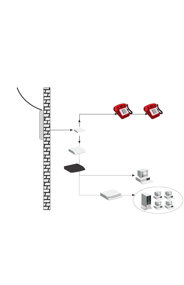
Installing a Full-Rate Connection
If you are using a full-rate (G.dmt) connection, your service provider will
attach the outside ADSL line to a data/voice splitter. Use a straight
through CAT-5 Ethernet cable (RJ-45) to connect the BARRICADE to
the cable/DSL modem.
Figure 2-3. Installing with a Splitter
Voice
Data
Residential
Connection
Point (NID)
Plain Old
Telephone
System (POTS)
or
Ethernet
hub or switch
Barricade
Splitter
Modem
C
ONNECT
THE
S
YSTEM
2-7
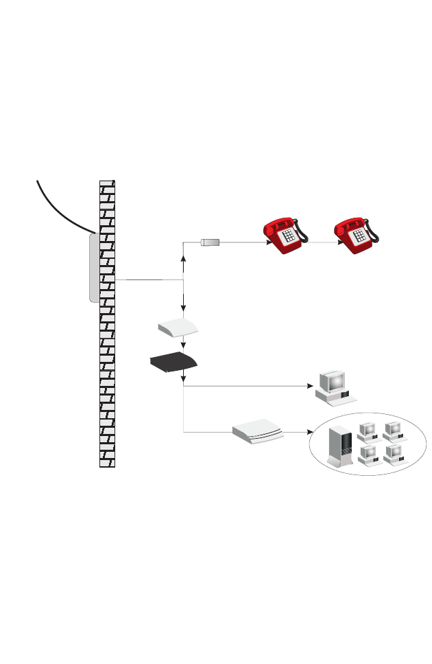
Installing a Splitterless Connection
If you are using a splitterless (G.lite) connection, then your service
provider will attach the outside ADSL line directly to your phone system.
Use a straight through CAT-5 Ethernet cable (RJ-45) to connect the
BARRICADE to the cable/DSL modem. You will have to add low-pass
filters to your phones as shown below:
Figure 2-4. Installing without a Splitter
Plain Old
Telephone
System (POTS)
Filter
or
Ethernet
hub or switch
Voice
& Data
Voice
& Data
Data
Voice
Residential
Connection
Point [Network
Interface
Device (NID)]
Barricade
Modem

I
NSTALLATION
2-8
Connecting the BARRICADE to your LAN
The four LAN ports on the BARRICADE auto-negotiate the connection
speed to 10 Mbps Ethernet or 100 Mbps Fast Ethernet, as well as the
transmission mode to half duplex or full duplex.
Use RJ-45 cables to connect any of the four LAN ports on the
BARRICADE to an Ethernet adapter on your PC. Otherwise, cascade any
of the LAN ports on the BARRICADE to an Ethernet hub or switch, and
then connect your PC or other network equipment to the hub or switch.
When inserting an RJ-45 connector, be sure the tab on the connector
clicks into position to ensure that it is properly seated.
Warning: Do not plug a phone jack connector into an RJ-45 port. This
may damage the BARRICADE. Instead, use only twisted-pair
cables with RJ-45 connectors that conform with FCC
standards.
Notes: 1. Use 100-ohm shielded or unshielded twisted-pair cable with
RJ-45 connectors for all Ethernet ports. Use Category 3, 4, or 5
for connections that operate at 10 Mbps, and Category 5 for
connections that operate at 100 Mbps.
2. Make sure each twisted-pair cable length does not exceed
100 meters (328 feet).

C
ONNECT
THE
S
YSTEM
2-9
Connect the Power Adapter
Plug the power adapter into the power socket on the side panel of the
BARRICADE, and the other end into a power outlet.
Check the power indicator on the front panel is lit. If the power i
ndicator is
not lit, refer to
“Troubleshooting” on page A-1.
In case of a power input failure, the BARRICADE will automatically
restart and begin to operate once the input power is restored.
If the BARRICADE is properly configured, it will take about 30 seconds
to establish a connection with the ADSL service provider after powering
up.

I
NSTALLATION
2-10

3-1
C
HAPTER
3
C
ONFIGURING
T
HE
C
LIENT
PC
After completing hardware setup by connecting all your network devices,
you need to configure your computer to connect to the BARRICADE.
You can either configure your computer to automatically obtain IP settings
(DHCP) or manually configure IP address settings (Static IP).
Depending on your operating system see:
“Windows 2000” on page 3-3,
“Windows XP” on page 3-9,
or
“Configuring Your Macintosh Computer” on page 3-15.

TCP/IP C
ONFIGURATION
3-2
TCP/IP Configuration
To access the Internet through the BARRICADE, you must configure the
network settings of the computers on your LAN to use the same IP subnet
as the BARRICADE. The default network settings for the BARRICADE
are:
IP Address: 192.168.2.1
Subnet Mask: 255.255.255.0
Note: These settings can be changed to fit your network requirements,
but you must first configure at least one computer to access the
BARRICADE’s web configuration interface in order to make the
required changes. (See “Configuring the BARRICADE” on page
4-1 for instructions on configuring the BARRICADE.)
C
ONFIGURING
T
HE
C
LIENT
PC
3-3
Windows 2000
DHCP IP Configuration
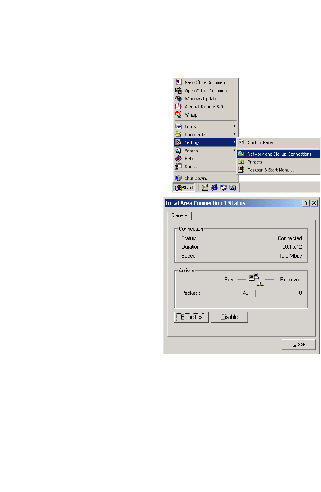
1. On the Windows desktop,
click Start/Settings/
Network and Dial-Up
Connections.
2. Click the icon that
corresponds to the
connection to your
BARRICADE.
3. The connection status
screen will open. Click
Properties.
TCP/IP C
ONFIGURATION
3-4
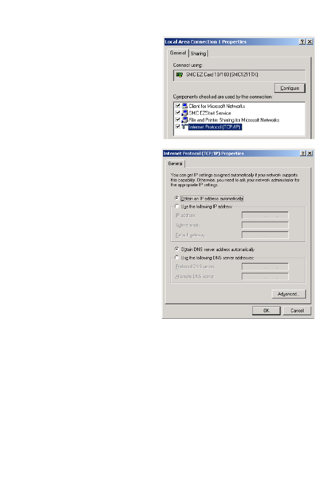
4. Double-click Internet
Protocol (TCP/IP).
5. If Obtain an IP address
automatically and Obtain
DNS server address
automatically are already
selected, your computer is
already configured for
DHCP. If not, select these
options now and click OK.
C
ONFIGURING
T
HE
C
LIENT
PC
3-5
Obtain IP Settings From Your BARRICADE
Now that you have configured your computer to connect to your
BARRICADE, it needs to obtain new network settings. By releasing old
DHCP IP settings and renewing them with settings from your
BARRICADE, you can verify that you have configured your computer
correctly.
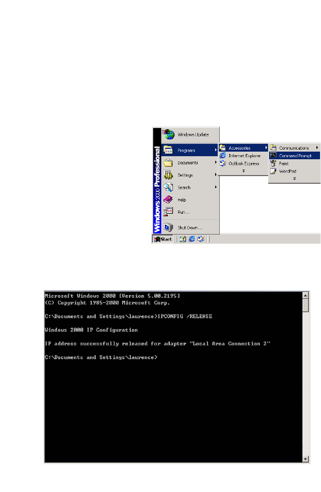
1. On the Windows desktop,
click Start/Programs/
Accessories/Command
Prompt.
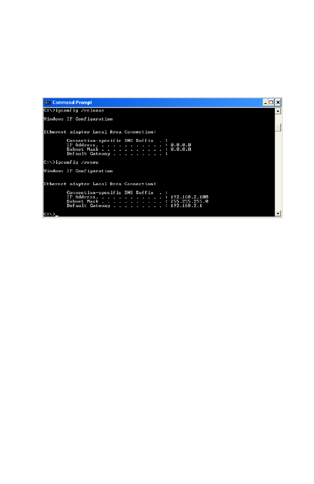
2. In the Command Prompt window, type “IPCONFIG /RELEASE”
and press the Enter key.
TCP/IP C
ONFIGURATION
3-6
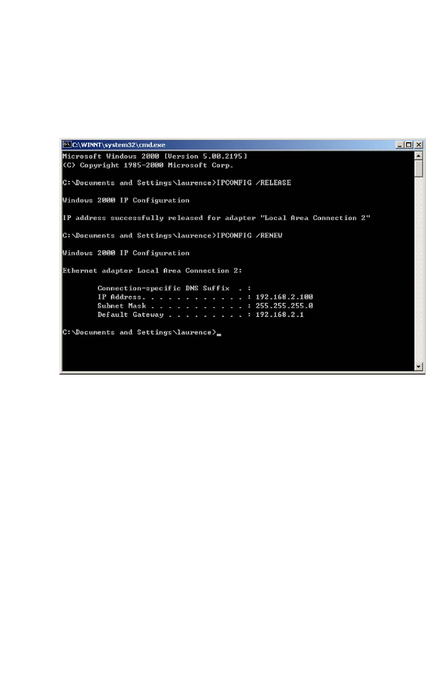
3. Type “IPCONFIG /RENEW” and press the Enter key. Verify that
your IP Address is now 192.168.2.xxx, your Subnet Mask is
255.255.255.0 and your Default Gateway is 192.168.2.1. These values
confirm that your BARRICADE is functioning correctly.
4. Type “EXIT” and press the Enter key to close the Command Prompt
window.
C
ONFIGURING
T
HE
C
LIENT
PC
3-7
Manual IP Configuration
1. Follow steps 1-4 in “DHCP IP Configuration” on page 3-3.
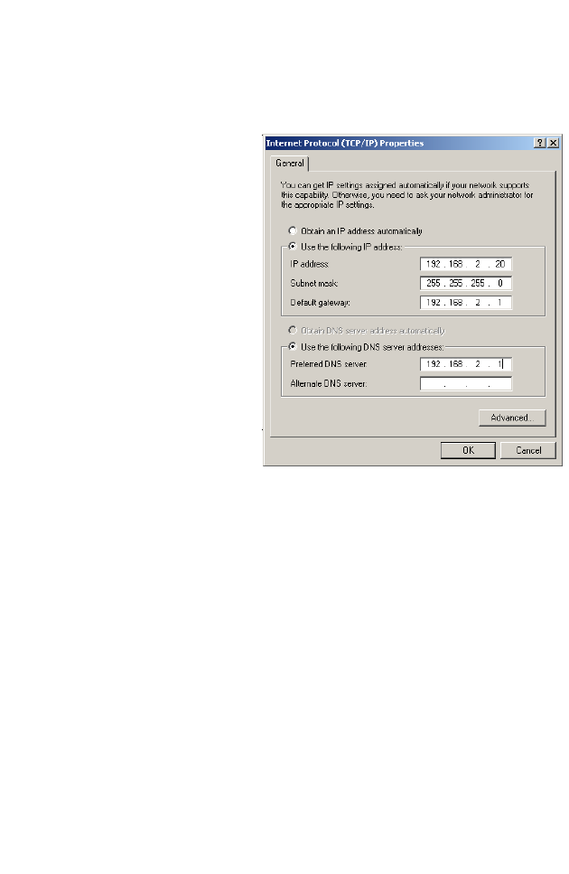
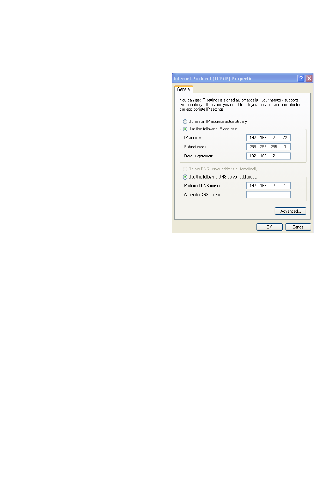
2. Select Use the
following IP address.
Enter an IP address
based on the default
network 192.168.2.x
(where x is
between 2
and 254), and use
255.255.255.0
for the
subnet mask. Use
192.168.2.1 for the
Default gateway field.
3. Select Use the
following DNS server
addresses.
4.
Enter the IP address for the
BARRICADE
in the Preferred DNS server
field
. This automatically relays DNS requests to the DNS server(s)
provided by your ISP. Otherwise, add a specific
DNS server into the
Alternate DNS Server field and click
OK
to close the dialog boxes
.
5. Record the configured information in the following table.
TCP/IP Configuration Setting
IP Address ____.____.____.____
Subnet Mask ____.____.____.____
Preferred DNS Server ____.____.____.____
Alternate DNS Server ____.____.____.____
Default Gateway ____.____.____.____
TCP/IP C
ONFIGURATION
3-8
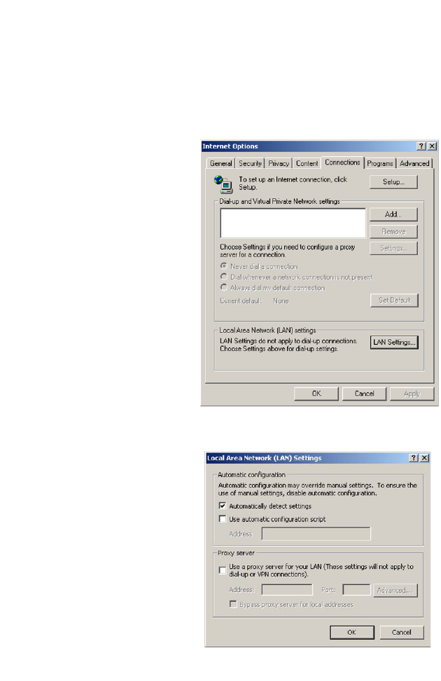
Disable HTTP Proxy
You need to verify that the “HTTP Proxy” feature of your web browser is
disabled. This is so that your browser can view the BARRICADE’s HTML
configuration pages.
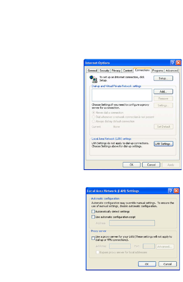
1. To disable the proxy in
Internet Explorer, click
Tools. Click Internet
Options... and then
the Connections tab,
shown on the right.
In
the Local Area Network
(LAN) settings section,
click
LAN Settings...
to display the Local
Area Network (LAN)
Settings pop-up window
below.
2. In the Proxy server
section, ensure the Use
a proxy server for
your LAN (These
settings will not apply
to dial-up or VPN
connections) check
box is not ticked.
3. Click OK.
C
ONFIGURING
T
HE
C
LIENT
PC
3-9
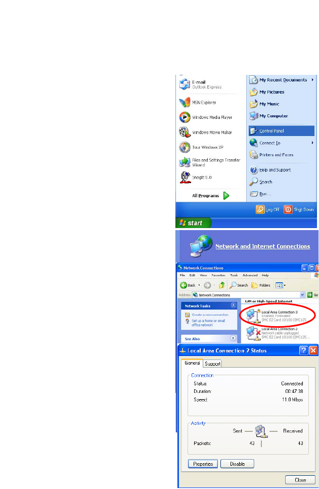
Windows XP
DHCP IP Configuration
1. On the Windows desktop,
click Start/Control Panel.
2. In the Control Panel window,
click Network and Internet
Connections.
3. The Network Connections
window will open. Locate and
double-click the Local Area
Connection icon for the
Ethernet adapter that is
connected to the BARRICADE.
4. In the connection status screen,
click Properties.
TCP/IP C
ONFIGURATION
3-10
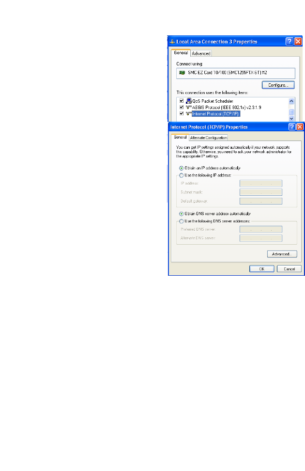
5. Double-click Internet
Protocol (TCP/IP).
6. If Obtain an IP address
automatically and Obtain
DNS server address
automatically are already
selected, your computer is
already configured for DHCP.
If not, select these options
now and click OK.
C
ONFIGURING
T
HE
C
LIENT
PC
3-11
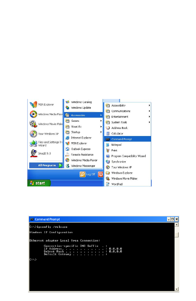
Obtain IP Settings From Your BARRICADE
Now that you have configured your computer to connect to your
BARRICADE, it needs to obtain new network settings. By releasing old
DHCP IP settings and renewing them with settings from your
BARRICADE, you can verify that you have configured your computer
correctly.
1. On the Windows desktop, click Start/Programs/Accessories/
Command Prompt.
2. In the Command Prompt window, type “IPCONFIG /RELEASE”
and press the Enter key.
TCP/IP C
ONFIGURATION
3-12
3. Type “IPCONFIG /RENEW” and press the Enter key. Verify that
your IP Address is now 192.168.2.xxx, your Subnet Mask is
255.255.255.0 and your Default Gateway is 192.168.2.1. These values
confirm that your BARRICADE is functioning correctly.
4. Type “EXIT” and press the Enter key to close the Command Prompt
window.
Your computer is now configured to connect to the BARRICADE.
C
ONFIGURING
T
HE
C
LIENT
PC
3-13
Manual IP Configuration
1. Follow steps 1-5 in “DHCP IP Configuration” on page 3-9.
2. Select Use the following IP
Address.
3. Enter an IP address based on
the default network
192.168.2.x (where x is
between 2 and 254), and use
255.255.255.0
for the subnet
mask. Use
192.168.2.1 for the
Default gateway field.
4. Select Use the following
DNS server addresses.
5. Enter the IP address for the BARRICADE in the Preferred DNS
server field. This automatically relays DNS requests to the DNS
server(s) provided by your ISP. Otherwise, add a specific DNS server
into the Alternate DNS Server field and click OK to close the dialog
boxes.
6. Record the configured information in the following table.
TCP/IP Configuration Setting
IP Address ____.____.____.____
Subnet Mask ____.____.____.____
Preferred DNS Server ____.____.____.____
Alternate DNS Server ____.____.____.____
Default Gateway ____.____.____.____
TCP/IP C
ONFIGURATION
3-14
Disable HTTP Proxy
You need to verify that the “HTTP Proxy” feature of your web browser is
disabled. This is so that your browser can view the BARRICADE’s HTML
configuration pages.
1. To disable the proxy in
Internet Explorer, click
Tools. Click Internet
Options... and then
the Connections tab,
shown on the right.
In
the Local Area Network
(LAN) settings section,
click
LAN Settings...
to display the Local
Area Network (LAN)
Settings pop-up window
below.
2. In the Proxy server
section, ensure the Use
a proxy server for
your LAN (These
settings will not apply
to dial-up or VPN
connections) check
box is not ticked.
3. Click OK.
C
ONFIGURING
T
HE
C
LIENT
PC
3-15
Configuring Your Macintosh Computer
You may find that the instructions here do not exactly match your
operating system. This is because these steps and screen shots were created
using Mac OS 10.2. Mac OS 7.x and above are similar, but may not be
identical to Mac OS 10.2.
Follow these instructions:
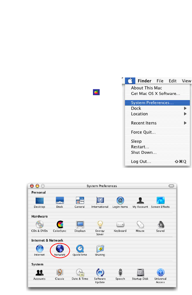
1. Pull down the Apple Menu . Click
System Preferences.
2. Double-click the Network icon in the
Systems Preferences window.

C
ONFIGURING
Y
OUR
M
ACINTOSH
C
OMPUTER
3-16
3. If Using DHCP Server is
already selected in the
Configure field, your
computer is already
configured for DHCP. If
not, select this option.
4. Your new settings are shown in the TCP/IP tab. Verify that your IP
Address is now 192.168.2.xxx, your Subnet Mask is 255.255.255.0 and
your Default Gateway is 192.168.2.1. These values confirm that your
BARRICADE is functioning.
5. Close the Network window.
Now your computer is configured to connect to the BARRICADE.
C
ONFIGURING
T
HE
C
LIENT
PC
3-17
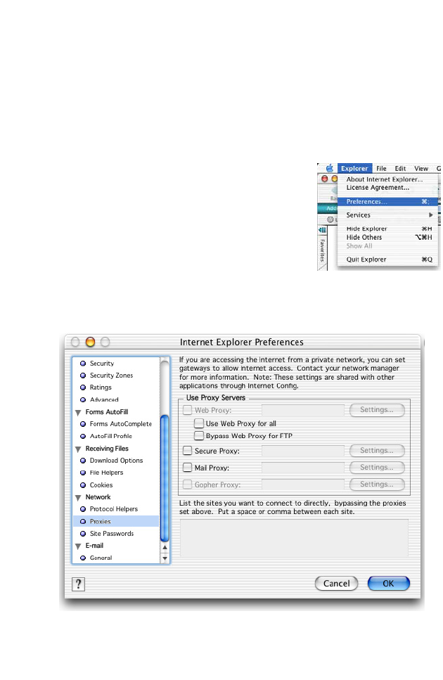
Disable HTTP Proxy
You need to verify that the “HTTP Proxy” feature of your web browser is
disabled. This is so that your browser can view the BARRICADE’s HTML
configuration pages. The following steps are for Internet Explorer.
Internet Explorer
1. Open Internet Explorer and click the Stop
button. Click Explorer/Preferences.
2. In the Internet Explorer Preferences window,
under Network, select Proxies.
3. Uncheck all check boxes and click OK.

C
ONFIGURING
Y
OUR
M
ACINTOSH
C
OMPUTER
3-18

4-1
C
HAPTER
4
C
ONFIGURING
THE
BARRICADE
After you have configured TCP/IP on a client computer, use a web
browser to configure the BARRICADE. The BARRICADE can be
configured by any Java-supported browser such as Internet Explorer 5.5 or
above. Using the web management interface, you can configure the
BARRICADE and view statistics to monitor network activity.
To access the BARRICADE’s management interface, enter the IP address
of the BARRICADE in your web browser:
http://192.168.2.1
(The BARRICADE automatically switches to Port 80 for management
access.)

C
ONFIGURING
THE
BARRICADE
4-2
Navigating the Web Browser Interface
The BARRICADE’s management interface consists of a Setup Wizard, a
Home Network Settings section, a Security section and an Advanced
Settings section.
Setup Wizard: Use the Setup Wizard for quick and easy configuration of
your Internet connection and basic LAN settings. Go to “Setup Wizard”
on page 4-5.
Home Network Settings: Use the Home Network Settings section to
configure your LAN, WAN and wireless settings. Go to “Home Network
Settings” on page 4-15.
Security: In this section, you can easily configure your wireless security
settings. Go to “Security” on page 4-32.
Advanced Settings: Advanced Settings supports more advanced
functions like NAT, system maintenance, SNMP and UPnP. Go to
“Advanced Settings” on page 4-59.

N
AVIGATING
THE
W
EB
B
ROWSER
I
NTERFACE
4-3
Making Configuration Changes
Configurable parameters have a dialog box or a drop-down list. Once a
configuration change has been made on a page, be sure to click the Apply
or Save Settings or NEXT button at the bottom of the page to enable
the new setting.
Note: To ensure proper screen refresh after a command entry, be sure
that Internet Explorer 5.5 is configured as follows: Under the
menu Tools/Internet Options.../General/Temporary Internet
Files/Settings..., the setting for Check for newer versions of
stored pages should be Every visit to the page.
C
ONFIGURING
THE
BARRICADE
4-4
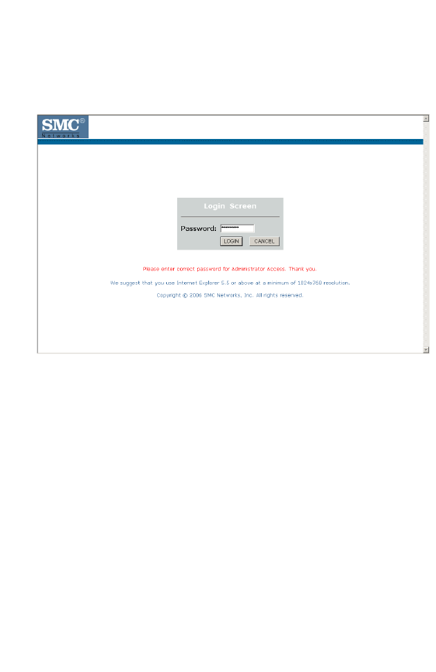
Login Screen
The Login screen automatically appears first.
Enter the default password “smcadmin” and then click LOGIN.
Note: Your password is case sensitive.
S
ETUP
W
IZARD
4-5
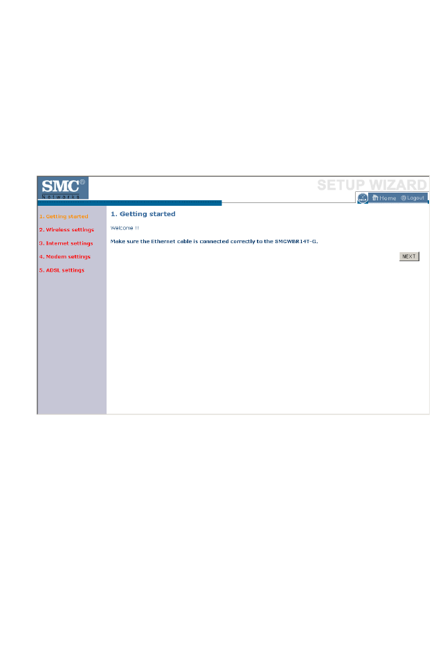
Setup Wizard
Getting Started
The Setup Wizard automatically appears by clicking on the Setup Wizard
button of the left-hand menu. The first item in the Setup Wizard is Getting
Started.
Simply click NEXT to proceed to the following screen and configure your
Wireless Settings.
C
ONFIGURING
THE
BARRICADE
4-6
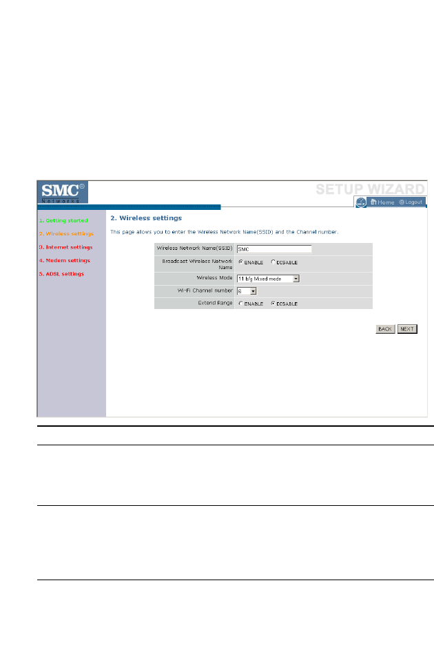
Wireless Settings
Enter your wireless network settings on this page. You must specify a
common radio channel and SSID (Service Set ID) to be used by the
BARRICADE and all of its wireless clients. Be sure you configure all of its
clients to the same value. For security purposes, you should change the
default SSID immediately.
Parameter Description
Wireless Network
Name (SSID)
The Service Set ID (SSID) is the name of your wireless
network. The SSID must be the same on the
BARRICADE and all of its wireless clients. (Default:
SMC)
Broadcast Wireless
Network Name
Enable or disable the broadcasting of the SSID. If you
disable broadcast of the SSID, only devices that have the
correct SSID can connect. This nullifies the wireless
network “discovery” feature of some products such as
Windows XP. (Default: Enable)
Wireless Mode This device supports the following modes: 11g only, 11b
only, 11b/g mixed mode, Super G-Dynamic Turbo and
Super G-Static Turbo. (Default: 11b/g mixed mode)

S
ETUP
W
IZARD
4-7
Super G
Atheros’ Super G is a series of intelligent mechanisms that engage when
additional bandwidth is available and/or needed. It increases the actual end
user throughput of an 802.11a/b/g network. These features include
bursting, compression, fast frames and Dynamic and Static Turbo. These
features are described briefly below.
Super G Feature Summary
Wi-Fi Channel
Number
The radio channel used by the BARRICADE and its
clients to communicate with each other. This channel
must be the same on the BARRICADE and all of its
wireless clients.
The BARRICADE will automatically assign itself a radio
channel, or you may select one manually. (Default: Ch 6)
Extend Range Increases the range of the BARRICADE. (Default:
Disable)
Feature Characteristics Benefit
Bursting - More data frames per given
time period
- Standards-based
- Relevant to STA
- Increase throughput via
overhead reduction
- 802.11e subset
- Advantage applies to any AP
Compression - Real-time hardware data
compression
- Standards-based Lempel Ziv
- Increased data throughput
using compressed frames
- No impact on host processor
Fast Frames - Utilizes frame aggregation
and timing modifications
- Increases throughput by
transmitting more data per
frame
Parameter Description

C
ONFIGURING
THE
BARRICADE
4-8
Dynamic Turbo - Similar to trunking
techniques used in Fast
Ethernet networks, utilizes
dual channels to “double”
transmission rates
- Analyzes environment and
adjusts bandwidth utilization
accordingly
- Maximizes bandwidth using
multiple channels
- Automatically adjusts to local
environment
Static Turbo - Utilizes dual channels to
“double” transmission rates
- Fixed dual-channel mode
- Maximizes bandwidth using
multiple channels
- Automatically set to use dual
channels
Feature Characteristics Benefit
S
ETUP
W
IZARD
4-9
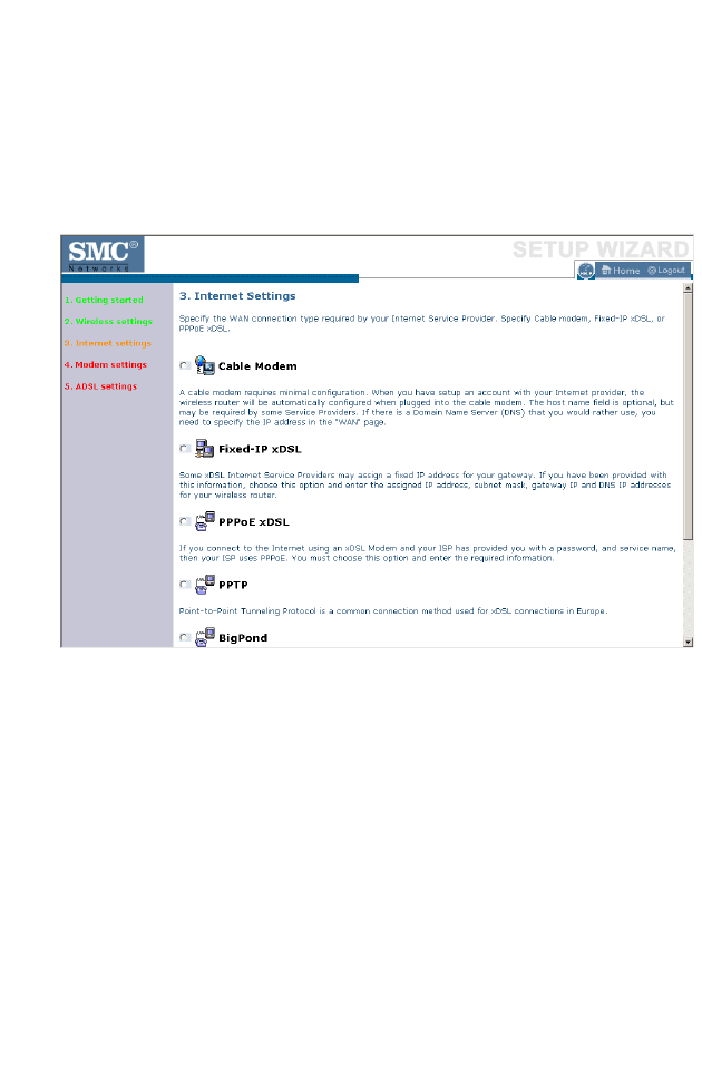
Internet Settings
Specify the WAN connection type required by your Internet Service
Provider. Specify Cable modem, Fixed-IP xDSL, PPPoE xDSL, PPTP or
BigPond.
Select your connection type to proceed. Click BACK to go back and
change your settings.
C
ONFIGURING
THE
BARRICADE
4-10
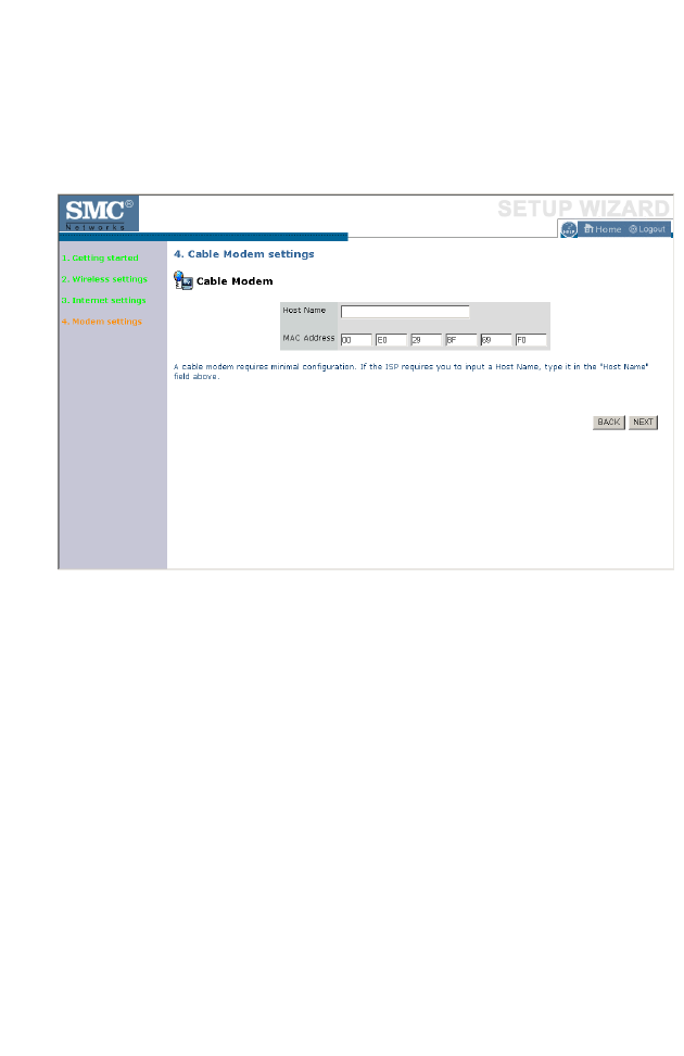
Cable Modem Settings
If the ISP requires you to input a Host Name, type it in the Host Name
field. The MAC Address field will be filled automatically.
Click NEXT to proceed, or BACK to change your settings.
S
ETUP
W
IZARD
4-11
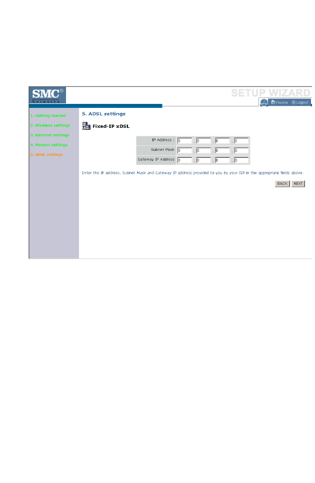
ADSL Settings - Fixed-IP xDSL
Enter the IP address, Gateway IP address, DNS IP address, and Subnet
Mask provided to you by your ISP in the appropriate fields below.
Click NEXT to proceed, or BACK to change your settings.
C
ONFIGURING
THE
BARRICADE
4-12
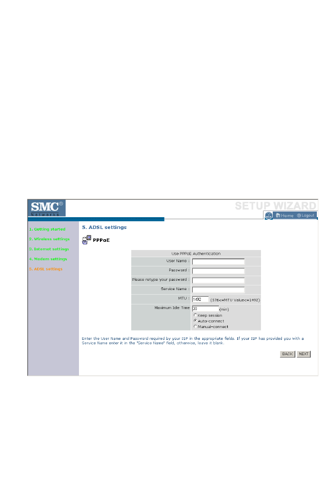
ADSL Settings - PPPoE
Enter the User Name and Password required by your ISP in the
appropriate fields. If your ISP has provided you with a Service Name enter
it in the “Service Name” field, otherwise, leave it blank. Leave the
Maximum Transmission Unit (MTU) at the default value (1454) unless you
have a particular reason to change it. Enter the maximum idle time for the
Internet connection. After this time has been exceeded the connection will
be terminated. Check Keep session to keep the session alive. Check the
Auto-connect check box to automatically re-establish the connection as
soon as you attempt to access the Internet again. Check the Manual-
connect check box to manually re-establish the connection.
Click NEXT to proceed, or BACK to change your settings.
Note: Clicking NEXT will not automatically connect the BARRICADE
to the Internet. The BARRICADE will only connect when you
explicitly request it to, for example, by launching your web
browser.
S
ETUP
W
IZARD
4-13
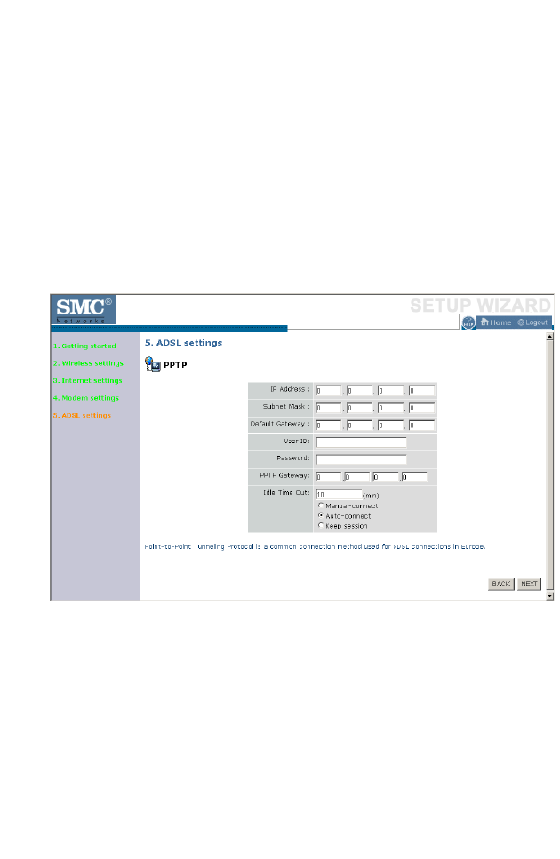
ADSL Settings - PPTP
Enter the User ID and Password required by your ISP in the appropriate
fields. Enter the Idle Time Out for the Internet connection. This is the
period of time for which the connection to the Internet is maintained
during inactivity. The default setting is 10 minutes. If your ISP charges you
by the minute, you should change the Idle Time Out to one minute. After
the Idle Time Out has expired, set the action you wish the BARRICADE
to take. You can tell the device to connect manually or automatically as
soon as you try to access the Internet again, or to keep the session alive.
Click NEXT to proceed, or BACK to change your settings.
C
ONFIGURING
THE
BARRICADE
4-14
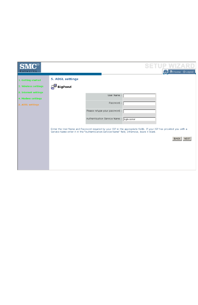
ADSL Settings - BigPond
If you use the BigPond Internet Service which is available in Australia,
enter the the User Name, Password and Authentication Service Name for
BigPond authentication.
Click NEXT to proceed, or BACK to change your settings.

H
OME
N
ETWORK
S
ETTINGS
4-15
Home Network Settings
Clicking the Home icon at any time, returns you to this home page. The
Main Menu links are used to navigate to other menus that display
configuration parameters and statistics.
Menu Description
Status Provides WAN connection type and status, firmware and hardware
version numbers, system IP settings, as well as DHCP, NAT, and firewall
information.
Displays the number of attached clients, the firmware versions, the
physical MAC address for each media interface, and the hardware version
and serial number.
Shows the security and DHCP client log.
LAN
Settings
Sets the TCP/IP configuration for the BARRICADE LAN interface and
DHCP clients.
WAN
Settings
Specifies the Internet connection settings.
Wireless Configures the radio frequency, SSID, and security for wireless
communications.
C
ONFIGURING
THE
BARRICADE
4-16
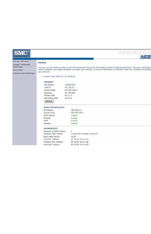
Status
The Status screen displays WAN/LAN connection status, firmware and
hardware version numbers, as well as information on DHCP clients
connected to your network. You can also view the Security Log.
H
OME
N
ETWORK
S
ETTINGS
4-17
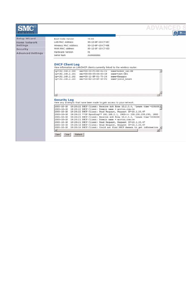
The security file, SMCWBR14T_logfile.log, may be saved by clicking Save
and choosing a location.

C
ONFIGURING
THE
BARRICADE
4-18
The following items are included on the Status screen:
Parameter Description
Current Time Shows the correct localized time.
INTERNET Displays WAN connection type and status.
Release Click on this button to disconnect from the WAN.
Renew Click on this button to establish a connection to the WAN.
Home Network
(LAN)
Displays system IP settings, as well as DHCP Server, Firewall,
UPnP and Wireless status.
INFORMATION Displays the number of attached clients, the firmware versions,
the physical MAC address for each media interface and for the
BARRICADE, as well as the hardware version and serial
number.
DHCP Client Log Displays information on DHCP clients on your network.
Security Log Displays illegal attempts to access your network.
Save Click on this button to save the security log file.
Clear Click on this button to delete the access log.
Refresh Click on this button to refresh the screen.
H
OME
N
ETWORK
S
ETTINGS
4-19
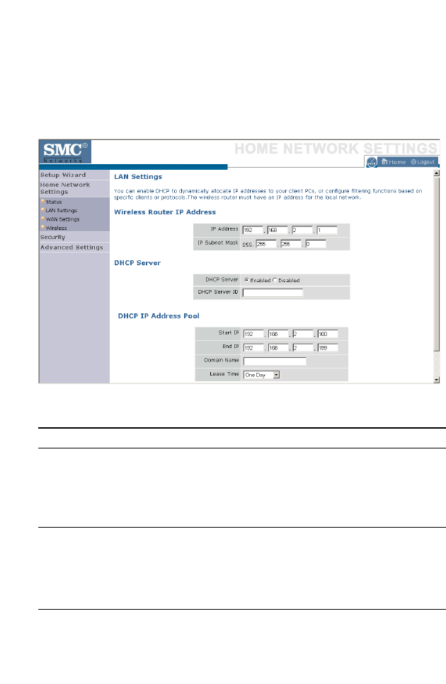
LAN Settings
You can enable DHCP to dynamically allocate IP addresses to your client
PCs, or configure filtering functions based on specific clients or protocols.
The BARRICADE must have an IP address for the local network.
The LAN Settings parameters are listed below.
Parameter Description
Wireless Router IP Address
IP Address The IP address of the BARRICADE.
IP Subnet Mask The IP subnet mask.
DHCP Server
DHCP Server DHCP allows individual computers to obtain the TCP/IP
configuration at startup from a centralized DHCP server. To
dynamically assign an IP address to a client PC, enable the
DHCP (Dynamic Host Configuration Protocol) function.
DHCP Server ID Enter the DHCP Server ID here.
DHCP IP Address
Pool
The DHCP IP Address Pool is the range of IP addresses set
aside for dynamic assignment to the computers on your
network.

C
ONFIGURING
THE
BARRICADE
4-20
Start IP This field indicates the first of the contiguous IP addresses in
the IP address pool.
End IP This field indicates the last of the contiguous IP addresses in
the IP address pool.
Domain Name The domain name is the name you assign to your network.
Lease Time The length of time the DHCP server will reserve the IP
address for each computer. Setting lease times for shorter
intervals such as one day or one hour frees IP addresses after
the specified period of time. This also means that a particular
computer’s IP address may change over time. If you have set
any advanced features such as DMZ, this is dependent on the
IP address. For this reason, you will not want the IP address
to change.
Parameter Description
H
OME
N
ETWORK
S
ETTINGS
4-21
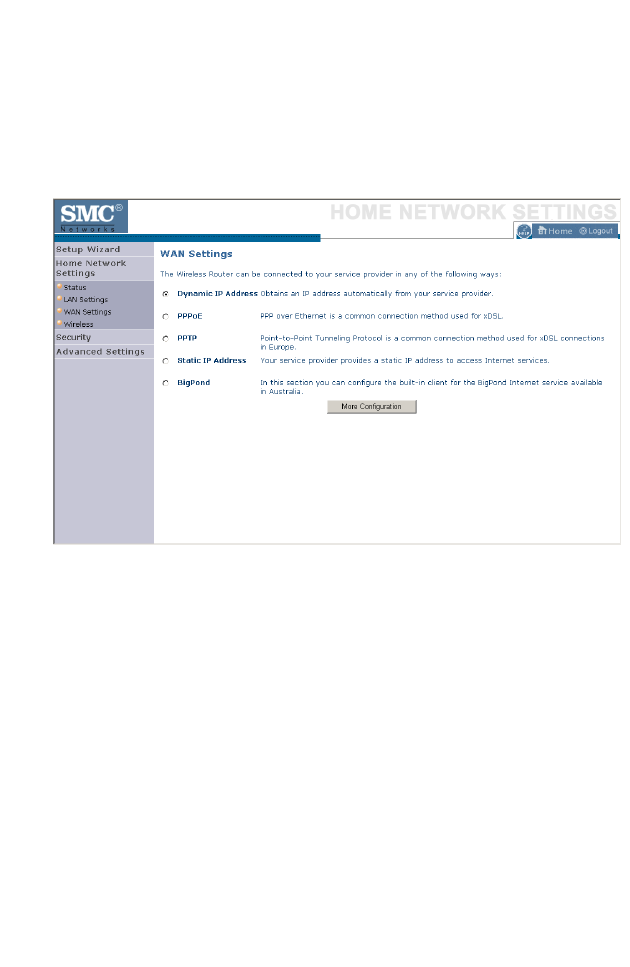
WAN Settings
Specify the WAN connection type required by your Internet Service
Provider. Specify Dynamic IP Address, PPPoE, PPTP, Static IP
Address or BigPond.
Select the connection type and click More Configuration.
C
ONFIGURING
THE
BARRICADE
4-22
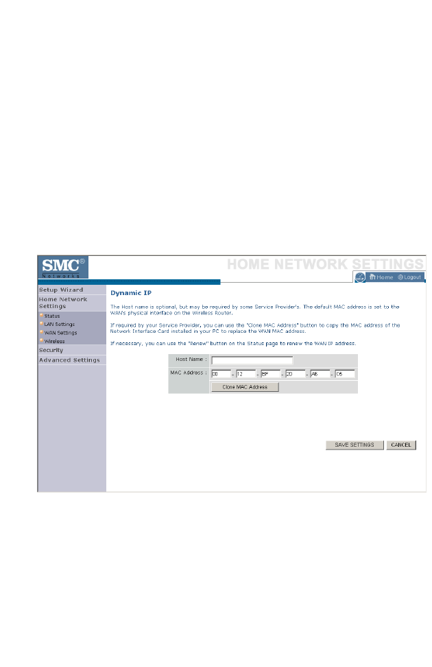
Dynamic IP
The Host name is optional, but may be required by some Service
Provider’s. The default MAC address is set to the WAN’s physical interface
on the BARRICADE.
If required by your Service Provider, you can use the Clone MAC
Address button to copy the MAC address of the Network Interface Card
(NIC) installed in your PC to replace the WAN MAC address.
If necessary, you can use the Renew button on the Status page to renew
the WAN IP address.
Note: Make sure you record the MAC address that you clone, so that if
you lose your settings you will be able to re-connect to the
Internet.
Click Save Settings to proceed, or Cancel to change your settings.
H
OME
N
ETWORK
S
ETTINGS
4-23
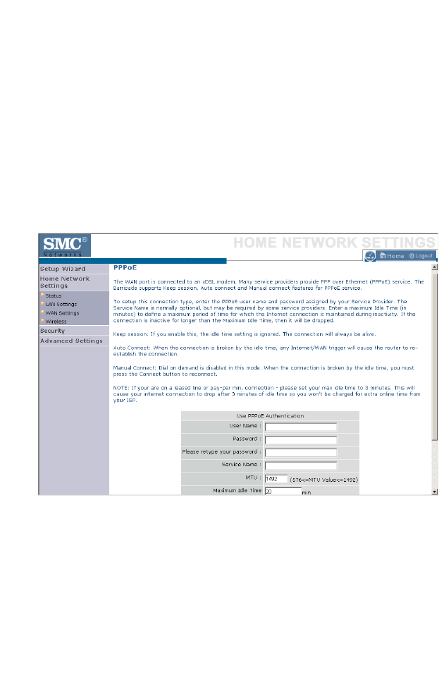
PPPoE
Enter the PPPoE user name and password assigned by your Service
Provider. The Service Name is normally optional, but may be required by
some service providers. Enter a Maximum Idle Time (in minutes) to define
a maximum period of time for which the Internet connection is
maintained during inactivity. If the connection is inactive for longer than
the Maximum Idle Time, then it will be dropped. You can enable the
Auto-reconnect option to automatically re-establish the connection as
soon as you attempt to access the Internet again.
Click Save Settings to proceed, or Cancel to change your settings.
C
ONFIGURING
THE
BARRICADE
4-24
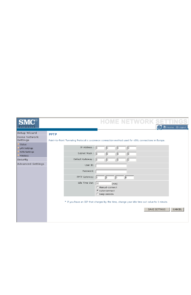
PPTP
The PPTP screen displays the IP Address, Subnet Mask and Default
Gateway of your BARRICADE. Enter the User ID and Password assigned
by your ISP in the appropriate fields. Enter the Idle Time Out for the
Internet connection. This is the period of time for which the connection to
the Internet is maintained during inactivity. The default setting is 10
minutes. If your ISP charges you by the minute, you should change the Idle
Time Out to one minute. After the Idle Time Out has expired, set the
action you wish the BARRICADE to take. You can tell the device to
connect manually or automatically as soon as you try to access the Internet
again, or to keep the session alive.
Click Save Settings to proceed, or Cancel to change your settings.
H
OME
N
ETWORK
S
ETTINGS
4-25
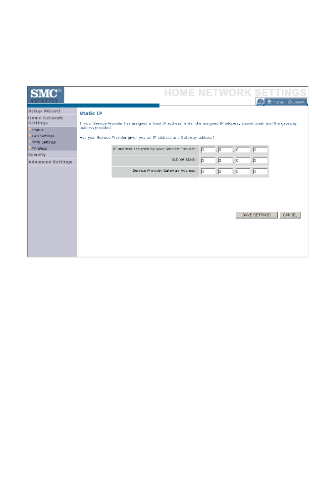
Static IP
If your Service Provider has assigned a fixed IP address, enter the assigned
IP address, subnet mask and the gateway address on this screen.
Click Save Settings to proceed, or Cancel to change your settings.
C
ONFIGURING
THE
BARRICADE
4-26
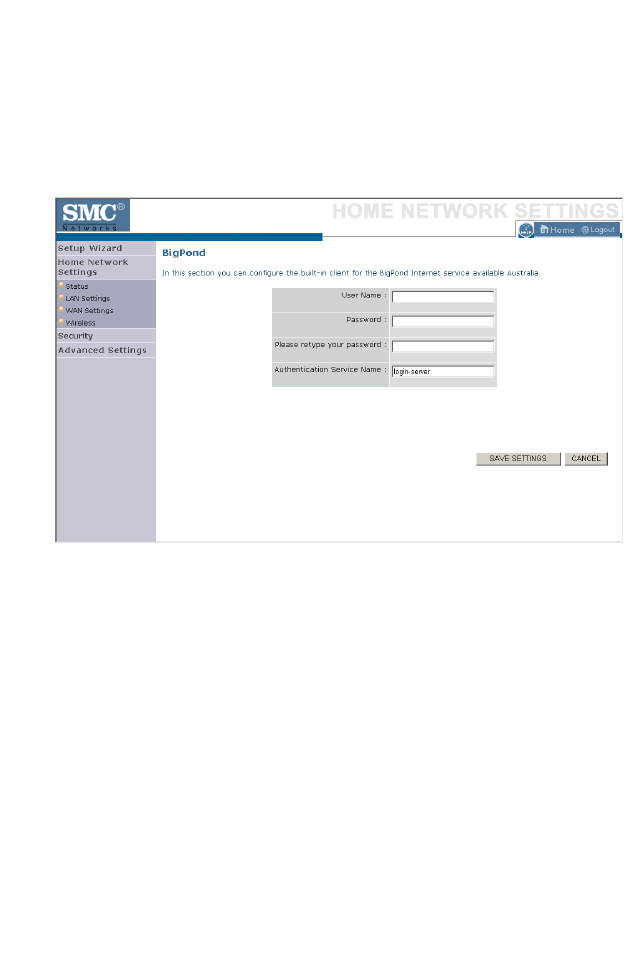
BigPond
BigPond is a service provider in Australia that uses a heartbeat system to
maintain the Internet connection. Configure the built-in client with your
user name, password and service name to get online.
Click Save Settings to proceed, or Cancel to change your settings.
H
OME
N
ETWORK
S
ETTINGS
4-27
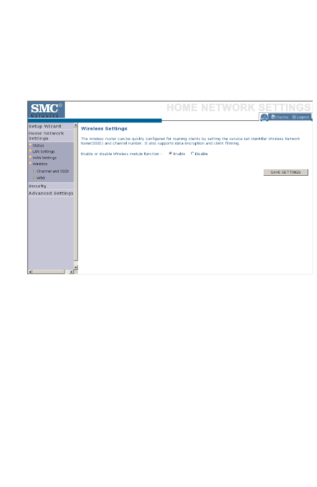
Wireless
The BARRICADE can be quickly configured for roaming clients by
setting the Service Set Identifier (SSID) and channel number. It supports
data encryption and client filtering.
To use the wireless feature, check the Enable check box and click Save
Settings. After clicking Save Settings, you will be asked to log in again.
See “Security” on page 4-32 for details on how to configure wireless
security.
C
ONFIGURING
THE
BARRICADE
4-28
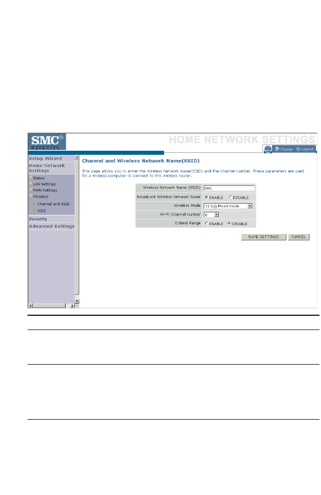
Channel and SSID
Enter your wireless network settings on this screen. You must specify a
common radio channel and SSID (Service Set ID) to be used by the
BARRICADE and all of its wireless clients. Be sure you configure all of its
clients to the same value. For security purposes, you should change the
default SSID immediately.
Parameter Description
Wireless Network
Name (SSID)
The Service Set ID (SSID) is the name of your wireless
network. The SSID must be the same on the BARRICADE
and all of its wireless clients. (Default: SMC)
Broadcast Wireless
Network Name
Enable or disable the broadcasting of the SSID. If you
disable broadcast of the SSID, only devices that have the
correct SSID can connect. This nullifies the wireless
network “discovery” feature of some products such as
Windows XP. (Default: Enable)
Wireless Mode This device supports the following modes; 11g only, 11b
only, 11b/g mixed mode, Super G-Dynamic Turbo and
Super G-Static Turbo. (Default: 11b/g mixed mode)

H
OME
N
ETWORK
S
ETTINGS
4-29
Wi-Fi Channel
Number
The radio channel used by the BARRICADE and its clients
to communicate with each other. This channel must be the
same on the BARRICADE and all of its wireless clients.
The BARRICADE will automatically assign itself a radio
channel, or you may select one manually. (Default: Ch 6)
Extend Range Extends the range of the BARRICADE. (Default: Disable)
Parameter Description
C
ONFIGURING
THE
BARRICADE
4-30
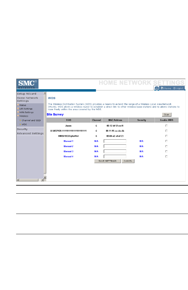
WDS
The Wireless Distribution System (WDS) provides a means to extend the
range of a Wireless Local Area Network (WLAN). WDS allows the
BARRICADE to establish a direct link to other wireless base stations and
allows clients to roam freely within the area covered by the WDS. To carry
out a site survey of available wireless base stations, click Scan.
Parameter Description
SSID The Service Set ID (SSID) is the name of your
wireless network. The SSID must be the same on
the BARRICADE and all of its wireless clients.
Channel This device supports the following modes 11g only,
11b only, 11b/g mixed mode, Super G-Dynamic
Turbo and Super G-Static Turbo.
MAC Address The media access control address (MAC address) is
a unique identifier attached to each wireless base
station.

H
OME
N
ETWORK
S
ETTINGS
4-31
Security Displays the security mechanism in use.
Enable WDS Enables the WDS feature. When enabled, up to 4
WDS links can be set by specifying their Wireless
MAC addresses in the MAC address table. Make
sure the same channel is in use on all devices.
(Default: Disable)
Parameter Description
C
ONFIGURING
THE
BARRICADE
4-32
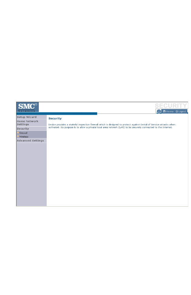
Security
The first menu item in the Security section is Firewall. The BARRICADE
provides a stateful inspection firewall which is designed to protect against
Denial of Service (DoS) attacks when activated. Its purpose is to allow a
private local area network (LAN) to be securely connected to the Internet.
The second menu item is Wireless. This section allows you to configure
wireless security settings according to your environment and the privacy
level required.
To configure your firewall settings, click Firewall in the left-hand menu.
S
ECURITY
4-33
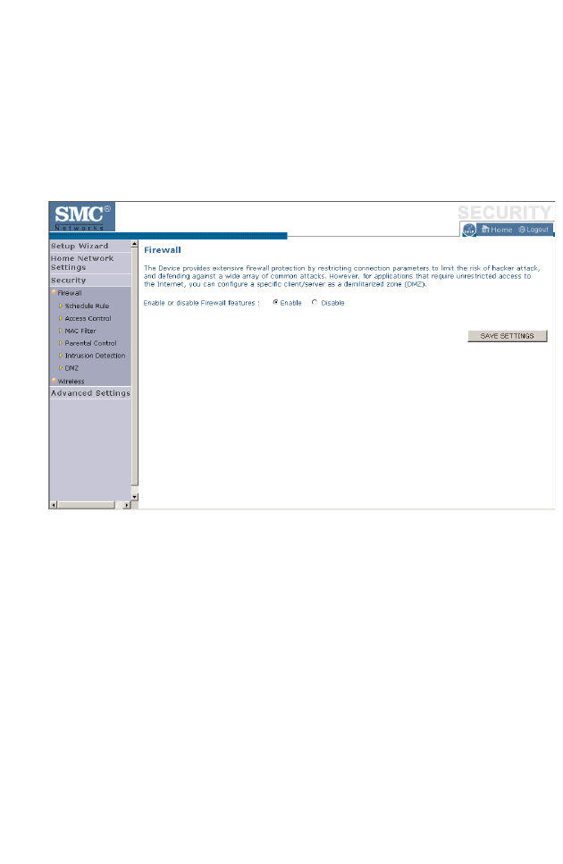
Firewall
The BARRICADE’s firewall inspects packets at the application layer,
maintains TCP and UDP session information including time-outs and the
number of active sessions, and provides the ability to detect and prevent
certain types of network attacks.
Network attacks that deny access to a network device are called Denial-of-
Service (DoS) attacks. DoS attacks are aimed at devices and networks with
a connection to the Internet. Their goal is not to steal information, but to
disable a device or network so users no longer have access to network
resources.
The BARRICADE protects against the following DoS attacks: IP
Spoofing, Land Attack, Ping of Death, IP with zero length, Smurf Attack,
UDP port loopback, Snork Attack, TCP null scan, and TCP SYN flooding.
(See page 4-46 for details.)
The firewall does not significantly affect system performance, so we advise
leaving it enabled to protect your network.
Enable the firewall feature, and click Save Settings to proceed.
C
ONFIGURING
THE
BARRICADE
4-34
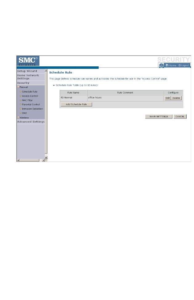
Schedule Rule
The first item listed in the Firewall section is Schedule Rule. You may filter
Internet access for local clients based on rules.
You may filter Internet access for local clients based on rules.
Each access control rule may be activated at a scheduled time. First, define
the schedule on the Schedule Rule page, then apply the rule on the Access
Control page.
To add a new rule, click Add Schedule Rule. Proceed to the following
page.
S
ECURITY
4-35
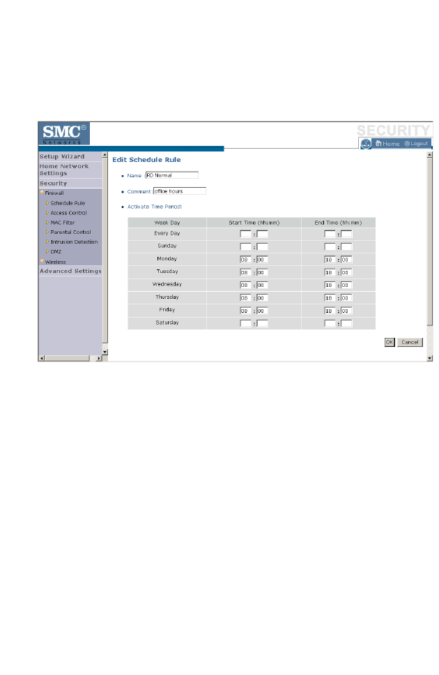
Edit Schedule Rule
1. Define the appropriate settings for a schedule rule (as shown on the
following screen).
2. Upon completion, click OK to save your schedule rules, and then click
Save Settings to make your settings to take effect.
C
ONFIGURING
THE
BARRICADE
4-36
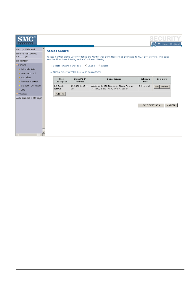
Access Control
Used in conjunction with the Schedule Rule screen, the Access Control
screen allows users to define the outgoing traffic permitted or
not-permitted. The default is to permit all outgoing traffic.
The BARRICADE can also limit the access of hosts within the local area
network (LAN). The MAC Filtering Table allows the BARRICADE to
enter up to 32 MAC addresses that are not allowed access to the WAN
port.
1. Click Add PC on the Access Control screen.
2. Define the appropriate settings for client PC services (as shown on the
following screen).
3. Click OK and then click Apply to save your settings.
The following items are displayed on the Access Control screen:
Parameter Description
Enable Filtering Function Enables or disables the filtering function.

S
ECURITY
4-37
Normal Filtering Table
(up to 10 computers)
Displays the IP address (or an IP address range)
filtering table.
Parameter Description
C
ONFIGURING
THE
BARRICADE
4-38
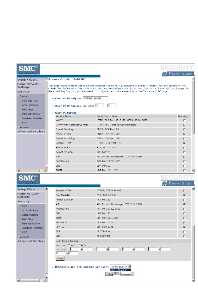
Access Control Add PC
Define the access control list in this page. The settings in the screen shot
below will block all email sending and receiving during weekdays (except
Friday). See “Schedule Rule” on page 4-34.
Define the appropriate settings for client PC services (as shown above). At
the bottom of this screen, you can set the scheduling function. You can set

S
ECURITY
4-39
this function to Always Blocking or to whatever schedule you have
defined in the Schedule Rule screen. Click OK to save your settings. The
added PC will now appear in the Access Control page.
For the URL/keyword blocking function, you will need to configure the
URL address or blocked keyword on the Parental Control page first. Click
Parental Control to add to the list of disallowed URL’s and keywords.
To enable scheduling, you also need to configure the schedule rule first.
Click Schedule Rule in the left-hand menu to set the times for which you
wish to enforce the rule.
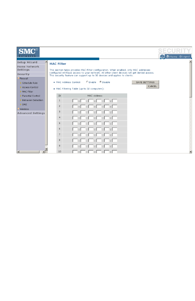
C
ONFIGURING
THE
BARRICADE
4-40
MAC Filter
Use this page to block access to your network using MAC addresses.
The BARRICADE can also limit the access of hosts within the local area
network (LAN). The MAC Filtering Table allows the BARRICADE to
enter up to 32 MAC addresses that are allowed access to the WAN port.
All other devices will be denied access. By default, this feature is disabled.
Click Save Settings to proceed, or Cancel to change your settings.
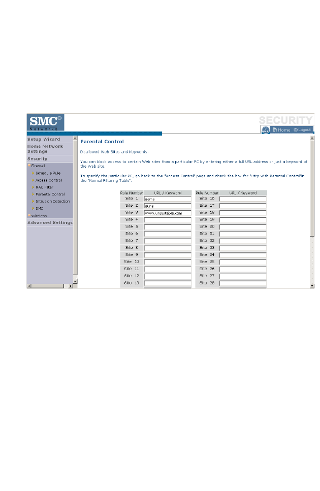
S
ECURITY
4-41
Parental Control
The BARRICADE allows the user to block access to web sites from a
particular PC by entering either a full URL address or just a keyword. This
feature can be used to protect children from accessing violent or
pornographic web sites.
You can define up to 30 sites or keywords here. To configure the Parental
Control feature, use the table to specify the web sites (www.somesite.com)
and/or keywords you want to block on your network.
To complete this configuration, you will need to create or modify an access
rule in “Access Control Add PC” on page 4-38. To modify an existing rule,
click the Edit option next to the rule you want to modify. To create a new
rule, click on the Add PC option.
From the Access Control, Add PC section, check the option for WWW
with Parental Control in the Client PC Service table to filter out the web
sites and keywords selected below, on a specific PC.
Click Save Settings to proceed, or Cancel to change your settings.
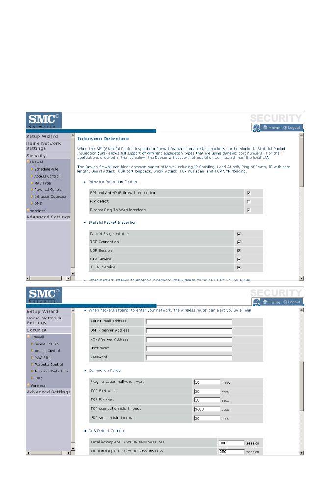
C
ONFIGURING
THE
BARRICADE
4-42
Intrusion Detection
The BARRICADE’s firewall inspects packets at the application layer,
maintains TCP and UDP session information including timeouts and
number of active sessions, and provides the ability to detect and prevent
certain types of network attacks such as Denial-of-Service (DoS) attacks.
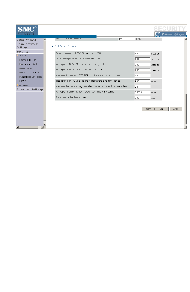
S
ECURITY
4-43
Network attacks that deny access to a network device are called DoS
attacks. DoS attacks are aimed at devices and networks with a connection
to the Internet. Their goal is not to steal information, but to disable a
device or network so users no longer have access to network resources.
The BARRICADE protects against DoS attacks including: Ping of Death
(Ping flood) attack, SYN flood attack, IP fragment attack (Teardrop
Attack), Brute-force attack, Land Attack, IP Spoofing attack, IP with zero
length, TCP null scan (Port Scan Attack), UDP port loopback, Snork
Attack.
Note: The firewall does not significantly affect system performance, so
we advise enabling the prevention features to protect your
network.

C
ONFIGURING
THE
BARRICADE
4-44
The table below lists the Intrusion Detection parameters and their
descriptions.
Parameter Defaults Description
Intrusion Detection
Feature
SPI and Anti-DoS
firewall protection No The Intrusion Detection feature of the
BARRICADE limits the access of incoming traffic
at the WAN port. When the Stateful Packet
Inspection (SPI) feature is turned on, all incoming
packets are blocked except those types marked
with a check in the SPI section at the top of the
screen.
RIP Defect Disabled If the router does not reply to an IPX RIP request
packet, it will stay in the input queue and not be
released. Accumulated packets could cause the
input queue to fill, causing severe problems for all
protocols. Enabling this feature prevents the
packets accumulating.
Discard Ping to
WAN Don’t
discard Prevents a ping on the router’s WAN port from
being routed to the network.

S
ECURITY
4-45
Stateful Packet
Inspection
Enabled This option allows you to select different
application types that are using dynamic port
numbers. If you wish to use Stateful Packet
Inspection (SPI) for blocking packets, click on the
Yes radio button in the “Enable SPI and Anti-DoS
firewall protection” field and then check the
inspection type that you need, such as Packet
Fragmentation, TCP Connection, UDP Session,
FTP Service and TFTP Service.
It is called a “stateful” packet inspection because it
examines the contents of the packet to determine
the state of the communication; i.e., it ensures that
the stated destination computer has previously
requested the current communication. This is a
way of ensuring that all communications are
initiated by the recipient computer and are taking
place only with sources that are known and trusted
from previous interactions. In addition to being
more rigorous in their inspection of packets,
stateful inspection firewalls also close off ports
until a connection to the specific port is requested.
When particular types of traffic are checked, only
the particular type of traffic initiated from the
internal LAN will be allowed. For example, if the
user only checks FTP Service in the Stateful Packet
Inspection section, all incoming traffic will be
blocked except for FTP connections initiated from
the local LAN.
When hackers
attempt to enter
your network,
we can alert you
by email
Your E-mail
Address Enter your email address.
SMTP Server
Address Enter your SMTP server address (usually the part
of the email address following the “@” sign).
POP3 Server
Address Enter your POP3 server address (usually the part
of the email address following the “@” sign).
User Name Enter your email account user name.
Parameter Defaults Description

C
ONFIGURING
THE
BARRICADE
4-46
Password Enter your email account password.
Connection Policy
Fragmentation
half-open wait 10 secs Configures the number of seconds that a packet
state structure remains active. When the timeout
value expires, the router drops the unassembled
packet, freeing that structure for use by another
packet.
TCP SYN wait 30 secs Defines how long the software will wait for a TCP
session to reach an established state before
dropping the session.
TCP FIN wait 5 secs Specifies how long a TCP session will be managed
after the firewall detects a FIN-exchange.
TCP connection
idle timeout 3600 secs
(1 hour) The length of time for which a TCP session will be
managed if there is no activity.
UDP session idle
timeout 30 secs The length of time for which a UDP session will
be managed if there is no activity.
DoS Detect Criteria
Total incomplete
TCP/UDP
sessions HIGH
300
sessions
Defines the rate of new unestablished sessions that
will cause the software to start deleting half-open
sessions.
Total incomplete
TCP/UDP
sessions LOW
250
sessions Defines the rate of new unestablished sessions that
will cause the software to stop deleting half-open
sessions.
Incomplete
TCP/UDP
sessions (per min.)
HIGH
250
sessions Maximum number of allowed incomplete
TCP/UDP sessions per minute.
Incomplete
TCP/UDP
sessions (per min.)
LOW
200
sessions Minimum number of allowed incomplete
TCP/UDP sessions per minute.
Maximum
incomplete
TCP/UDP
sessions number
from same host
10
sessions Maximum number of incomplete TCP/UDP
sessions from the same host.
Parameter Defaults Description

S
ECURITY
4-47
Note: We do not recommend modifying the default parameters shown
above.
Click Save Settings to proceed, or Cancel to change your settings.
Incomplete
TCP/UDP
sessions detect
sensitive time
period
300 msecs Length of time before an incomplete TCP/UDP
session is detected as incomplete.
Maximum
half-open
fragmentation
packet
number from
same host
30
sessions Maximum number of half-open fragmentation
packets from the same host.
Half-open
fragmentation
detect sensitive
time period
1 sec Length of time before a half-open fragmentation
session is detected as half-open.
Flooding cracker
block time 300 secs Length of time from detecting a flood attack to
blocking the attack.
Parameter Defaults Description
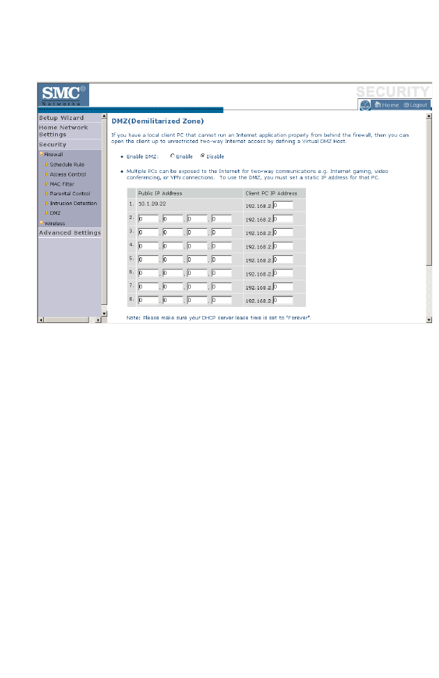
C
ONFIGURING
THE
BARRICADE
4-48
DMZ
If you have a client PC that cannot run an Internet application properly
from behind the firewall, you can open the client up to unrestricted
two-way Internet access. Enter the IP address of a DMZ (Demilitarized
Zone) host on this screen. Adding a client to the DMZ may expose
your local network to a variety of security risks, so only use this option
as a last resort.
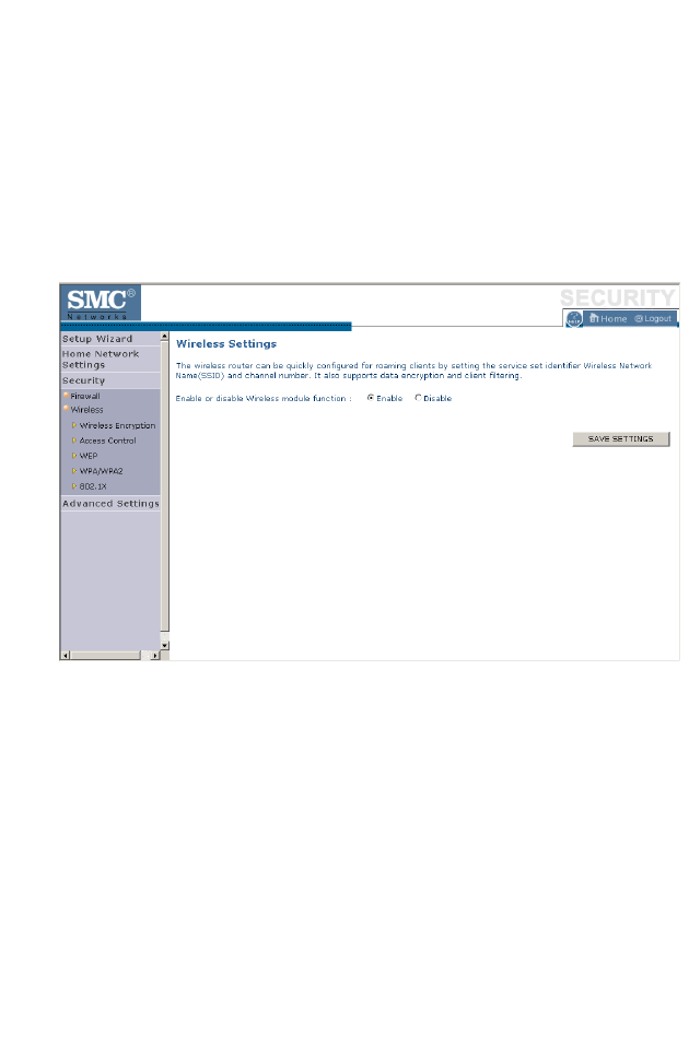
S
ECURITY
4-49
Wireless
The BARRICADE can be quickly configured for roaming clients by
setting the Service Set Identifier (SSID) and channel number. It supports
data encryption and client filtering.
To use the wireless feature, check the Enable check box and click Save
Settings.
To begin configuring your wireless security settings, click Wireless
Encryption.
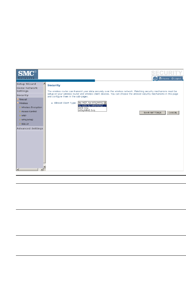
C
ONFIGURING
THE
BARRICADE
4-50
Wireless Encryption
The BARRICADE can transmit your data securely over a wireless
network. Matching security mechanisms must be set up on your
BARRICADE and your wireless client devices. Select the most suitable
security mechanism from the drop-down list on this screen.
Click Save Settings to proceed, or Cancel to change your settings.
Parameter Description
No WEP, No WPA/WPA2 Disables all wireless security. To make it easier to
set up your wireless network, we recommend
enabling this setting initially. By default, wireless
security is disabled.
WEP Only Once you have your wireless network in place, the
minimum security we recommend is to enable the
legacy security standard, Wired Equivalent Privacy
(WEP). See “WEP” on page 4-52.
WPA/WPA2 Only For maximum wireless security, you should enable
the WPA/WPA2 option. See “WPA/WPA2” on
page 4-54.
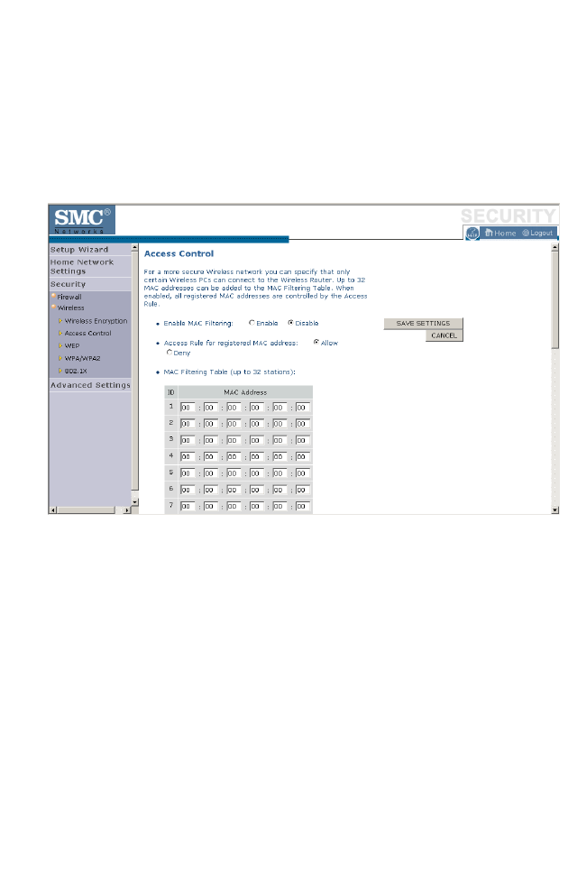
S
ECURITY
4-51
Access Control
For a more secure wireless network you can specify that only certain
wireless clients can connect to the BARRICADE. Up to 32 MAC
addresses can be added to the MAC Filtering Table. When enabled, all
registered MAC addresses are controlled by the Access Rule.
By default, this MAC filtering feature is disabled.
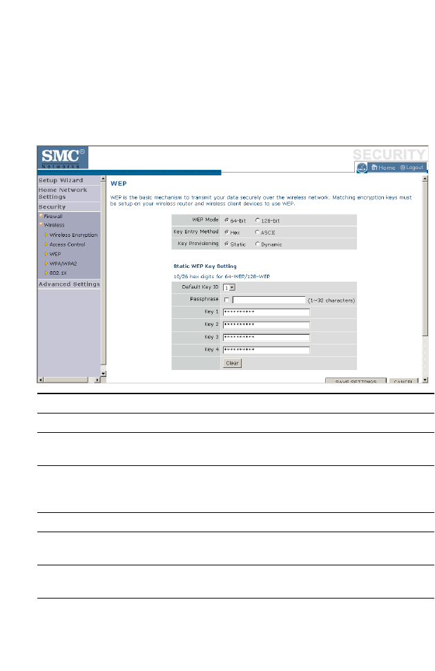
C
ONFIGURING
THE
BARRICADE
4-52
WEP
WEP is the basic mechanism to transmit your data securely over a wireless
network. Matching encryption keys must be set up on your BARRICADE
and and each of your wireless client devices.
Parameter Description
WEP Mode Select 64-bit or 128-bit key to use for encryption.
Key Entry Method Select hexadecimal (Hex) or ASCII for the key entry
method.
Key Provisioning Select Static if there is only one fixed key for encryption. If
you want to select Dynamic, you need to enable 802.1X
function first.
Default Key ID Choose which key to use as default.
Passphrase Check the Passphrase check box to generate a key
automatically.
Key 1~4 The BARRICADE supports up to 4 keys. You select the
default key.

S
ECURITY
4-53
You may automatically generate encryption keys or manually enter the
keys. To generate the key automatically with passphrase, check the
Passphrase box, and enter a string of characters. Select the default key
from the drop-down menu. Click APPLY.
Note: The passphrase can consist of up to 63 alphanumeric characters.
Hexadecimal Keys
A hexadecimal key is a mixture of numbers and letters from A-F and 0-9.
64-bit keys are 10 digits long and can be divided into five two-digit
numbers. 128-bit keys are 26 digits long and can be divided into 13
two-digit numbers.
ASCII Keys
There are 95 printable ASCII characters:
!"#$%&'()*+,-./0123456789:;<=>?
@ABCDEFGHIJKLMNOPQRSTUVWXYZ[\]^_
`abcdefghijklmnopqrstuvwxyz{|}~
Having selected and recorded your key, click Save Settings to proceed, or
Cancel to go back.
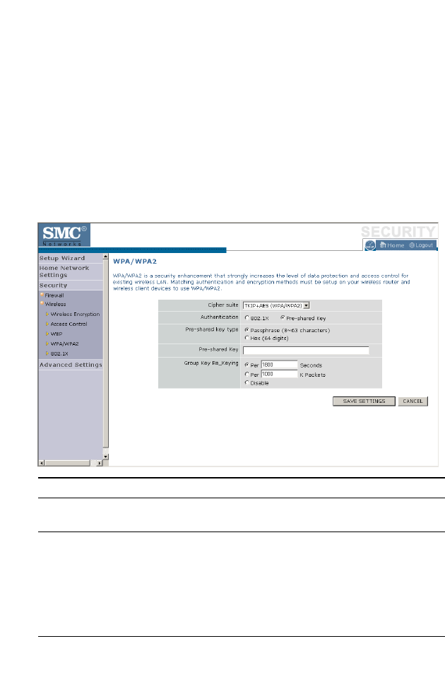
C
ONFIGURING
THE
BARRICADE
4-54
WPA/WPA2
WPA/WPA2 is a security enhancement that strongly increases the level of
data protection and access control for existing wireless LAN. Matching
authentication and encryption methods must be set up on your
BARRICADE and wireless client devices to use WPA/WPA2. To use
WPA, your wireless network cards must be equipped with software that
supports WPA. A security patch from Microsoft is available for free
download (for XP only).
Parameter Description
Cipher Suite The security mechanism used in WPA for encryption.
Select TKIP+AES (WPA/WPA2) or AES WPA2 Only.
Authentication Select 802.1X or Pre-shared Key for the authentication
method.
- 802.1X: for the enterprise network with a RADIUS
server.
- Pre-shared key: for the SOHO network environment
without an authentication server.
Pre-shared key type Select the key type to be used in the Pre-shared Key.

S
ECURITY
4-55
WPA
WPA addresses all known vulnerabilities in WEP, the original, less secure
40 or 104-bit encryption scheme in the IEEE 802.11 standard. WPA also
provides user authentication, since WEP lacks any means of
authentication. Designed to secure present and future versions of IEEE
802.11 devices, WPA is a subset of the IEEE 802.11i specification.
WPA replaces WEP with a strong new encryption technology called
Temporal Key Integrity Protocol (TKIP) with Message Integrity Check
(MIC). It also provides a scheme of mutual authentication using either
IEEE 802.1X/Extensible Authentication Protocol (EAP) authentication
or pre-shared key (PSK) technology. The passphrase can consist of up to
32 alphanumeric characters.
WPA2
Launched in September 2004 by the Wi-Fi Alliance, WPA2 is the certified
interoperable version of the full IEEE 802.11i specification which was
ratified in June 2004. Like WPA, WPA2 supports IEEE 802.1X/EAP
authentication or PSK technology. It also includes a new advanced
encryption mechanism using the Counter-Mode/CBC-MAC Protocol
(CCMP) called the Advanced Encryption Standard (AES).
Pre-shared Key Type the key here.
Group Key Re_Keying The period of renewing the broadcast/multicast key.
Parameter Description

C
ONFIGURING
THE
BARRICADE
4-56
WPA and WPA2 Mode Types
Click Save Settings to proceed, or Cancel to change your settings.
WPA WPA2
Enterprise Mode Authentication:
IEEE 802.1X/EAP
Encryption:
TKIP/MIC
Authentication:
IEEE 802.1X/EAP
Encryption:
AES-CCMP
SOHO Mode Authentication:
PSK
Encryption:
TKIP/MIC
Authentication:
PSK
Encryption:
AES-CCMP
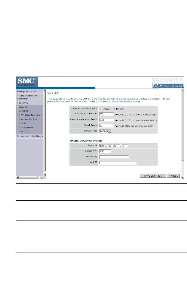
S
ECURITY
4-57
802.1X
If 802.1X is used in your network, then you should enable this function for
the BARRICADE. This screen allows you to set the 802.1X parameters.
802.1X is a method of authenticating a client wireless connection. Enter
the parameters below to connect the BARRICADE to the Authentication
Server.
Parameter Description
802.1X Authentication Enable or disable the authentication function.
Session Idle Timeout This is the time (in seconds) that a session will sit inactive
before terminating. Set to 0 if you do not want the session
to timeout. (Default: 300 seconds)
Re-Authentication
Period
The interval time (in seconds) after which the client will
be asked to re-authenticate. For example, if you set this to
30 seconds, the client will have to re-authenticate every 30
seconds. Set to 0 for no re-authentication.
(Default: 3600 seconds)
Quiet Period This is the interval time (in seconds) for which the
BARRICADE will wait between failed authentications.
(Default: 60 seconds)
Server Type Sets the authentication server type.

C
ONFIGURING
THE
BARRICADE
4-58
802.1X
The use of IEEE 802.1X offers an effective framework for authenticating
and controlling user traffic to a protected network, as well as dynamically
varying encryption keys. 802.1X ties EAP (Extensible Authentication
Protocol) to both the wired and wireless LAN media and supports
multiple authentication methods, such as token cards, Kerberos, one-time
passwords, certificates, and public key authentication.
Click Save Settings to proceed, or Cancel to change your settings.
Server IP Set the IP address of your RADIUS server.
Server Port Set the connection port that is configured on the radius
server.
Secret Key The 802.1X secret key used to configure the
BARRICADE.
NAS-ID Defines the request identifier of the Network Access
Server.
Parameter Description

A
DVANCED
S
ETTINGS
4-59
Advanced Settings
To configure the advanced settings such as NAT, Maintenance, System
settings and UPnP, click Advanced Settings.
Note: Changing some of the device settings in the Advanced Settings
mode may cause the BARRICADE to become unresponsive.
The BARRICADE’s advanced management interface contains 6 main
menu items as described in the following table.
Menu Description
NAT Shares a single ISP account with multiple users, sets up virtual
servers.
Maintenance Allows you to backup, restore, reset, and upgrade the
BARRICADE’s firmware.
System Sets the local time zone, the password for administrator access, the
IP address of a PC that will be allowed to manage the BARRICADE
remotely, and the IP address of a Domain Name Server.
SNMP Community string and trap server setting.
UPnP Universal Plug and Play (UPnP) allows for simple and robust
connectivity between external devices and your PC.
Routing Sets routing parameters and displays the current routing table.
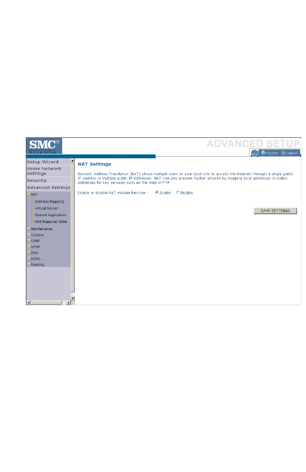
C
ONFIGURING
THE
BARRICADE
4-60
NAT
The first menu item in the Advanced Settings section is Network Address
Translation (NAT). This process allows all of the computers on your home
network to use one IP address. Using the NAT capability of the
BARRICADE, you can access the Internet from any computer on your
home network without having to purchase more IP addresses from your
ISP.
To use the NAT feature, check the Enable radio button and click Save
Settings.
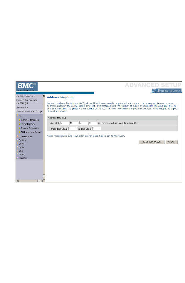
A
DVANCED
S
ETTINGS
4-61
Address Mapping
Network Address Translation (NAT) allows IP addresses used in a private
local network to be mapped to one or more addresses used in the public,
global Internet. This feature limits the number of public IP addresses
required from the ISP and also maintains the privacy and security of the
local network. We allow one public IP address to be mapped to a pool of
local addresses.
Click Save Settings to proceed, or Cancel to change your settings.
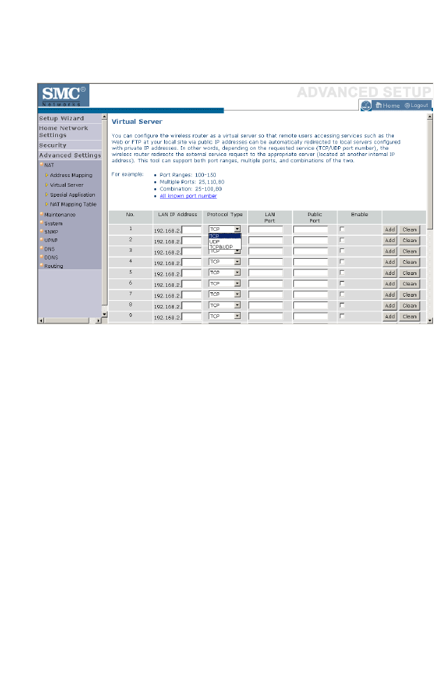
C
ONFIGURING
THE
BARRICADE
4-62
Virtual Server
Using this feature, you can put PCs with public IPs and PCs with private
IPs in the same LAN area.
If you configure the BARRICADE as a virtual server, remote users
accessing services such as web or FTP at your local site via public IP
addresses can be automatically redirected to local servers configured with
private IP addresses. In other words, depending on the requested service
(TCP/UDP port number), the BARRICADE redirects the external service
request to the appropriate server (located at another internal IP address).
For example, if you set Type/Public Port to TCP/80 (HTTP or web) and
the Private IP/Port to 192.168.2.2/80, then all HTTP requests from
outside users will be transferred to 192.168.2.2 on port 80. Therefore, by
just entering the IP address provided by the ISP, Internet users can access
the service they need at the local address to which you redirect them.
The more common TCP service ports include:
HTTP: 80, FTP: 21, Telnet: 23, and POP3: 110.
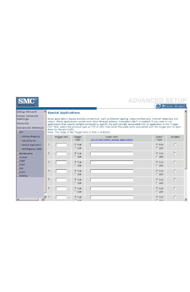
A
DVANCED
S
ETTINGS
4-63
Special Applications
Some applications, such as Internet gaming, videoconferencing, Internet
telephony and others, require multiple connections. These applications
cannot work with Network Address Translation (NAT) enabled. If you
need to run applications that require multiple connections, use the
following screen to specify the additional public ports to be opened for
each application.
Click the List of well known special applications link for more
information.
Specify the public port number normally associated with an application in
the Trigger Port field. Set the protocol type to TCP or UDP, then enter
the ports that the application requires. The ports may be in the format of a
single port, or in a range, e.g., 72-96, or a combination of both.
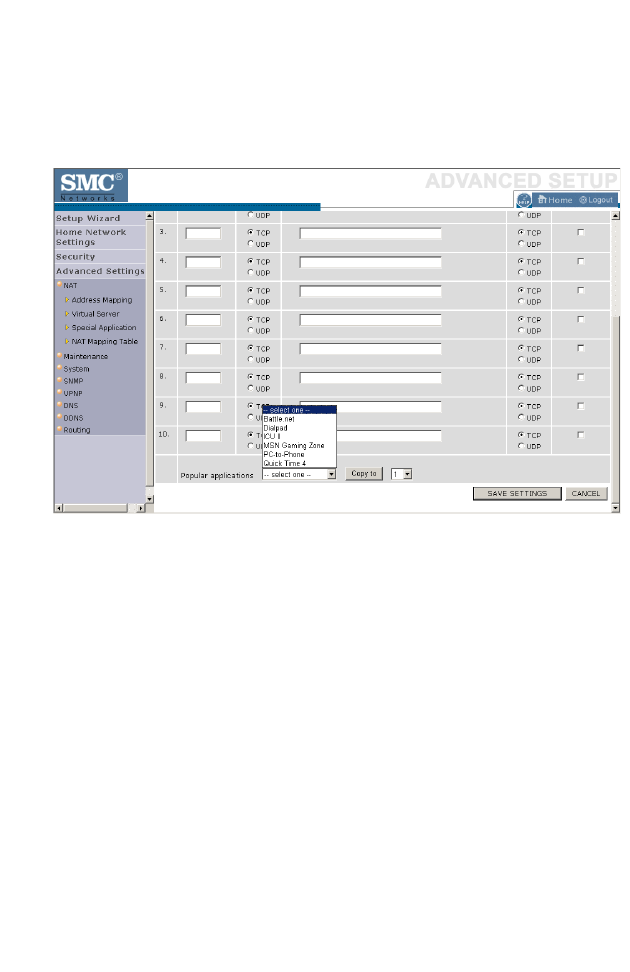
C
ONFIGURING
THE
BARRICADE
4-64
Popular applications requiring multiple ports are listed in the Popular
Applications field. From the drop-down list, choose the application and
then choose a row number to copy this data into.
Note: Choosing a row that already contains data will overwrite the
current settings.
For a full list of ports and the services that run on them, see
www.iana.org/assignments/port-numbers
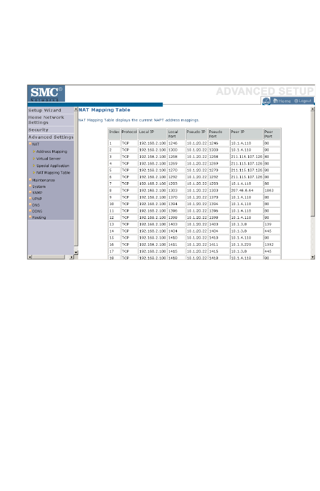
A
DVANCED
S
ETTINGS
4-65
NAT Mapping Table
This page displays the current NAPT (Network Address Port Translation)
address mappings.
The NAT address mappings are listed 20 lines per page, click the control
buttons to move forwards and backwards. As the NAT mapping is
dynamic, a Refresh button is provided to refresh the NAT Mapping Table
with the most updated values.
The content of the NAT Mapping Table is described as follows:
• Protocol - protocol of the flow.
• Local IP - local (LAN) host’s IP address for the flow.
• Local Port - local (LAN) host’s port number for the flow.
• Pseudo IP - translated IP address for the flow.
• Pseudo Port - translated port number for the flow.
• Peer IP - remote (WAN) host’s IP address for the flow.
• Peer Port - remote (WAN) host’s port number for the flow.
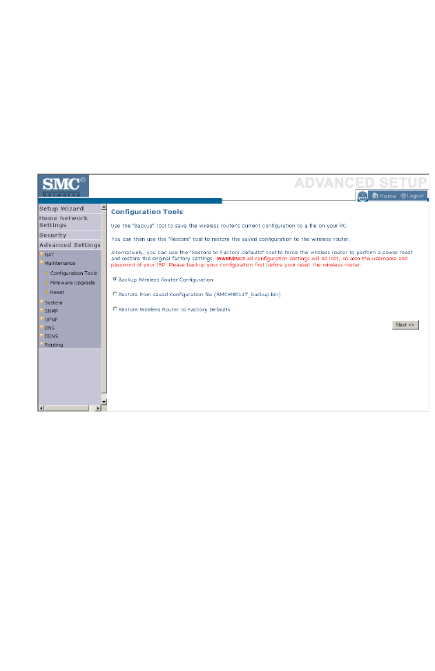
C
ONFIGURING
THE
BARRICADE
4-66
Maintenance
Use the Maintenance menu to back up the current settings, to restore
previously saved settings, or to restore the factory default settings.
Configuration Tools
Check Backup Wireless Router Configuration and click NEXT to save
your BARRICADE’s configuration to a file named config.bin on your PC.
You can then check the Restore from saved Configuration file
(SMCWBR14T_backup.bin) radio button and click NEXT to restore
the saved backup configuration file.
To restore the factory settings, check Restore Wireless Router to
Factory Defaults and click NEXT. You will be asked to confirm your
decision.
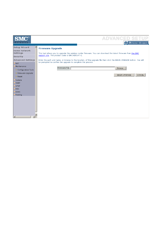
M
AINTENANCE
4-67
Firmware Upgrade
Use this screen to update the firmware to the latest version.
Go to www.smc.com to find the latest firmware. Download the firmware
to your hard drive first. Click Browse... to locate the saved file. After
locating the new firmware file, click BEGIN UPGRADE. Follow the
instructions to complete the upgrade. After restarting, check the Status
page to make sure the device is running the new code.
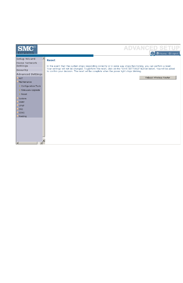
C
ONFIGURING
THE
BARRICADE
4-68
Reset
Perform a reset from this screen.
To perform a system reset, click the Reboot Wireless Router button in
the screen above. The configurations that you have set previously will not
be changed back to the factory default settings.
Note: You may also use the blue Reset button on the rear panel of the
BARRICADE to perform a reset. Push for one second to perform
a reboot. All of your settings will remain upon restarting. Push for
six seconds to return the BARRICADE to factory default settings.
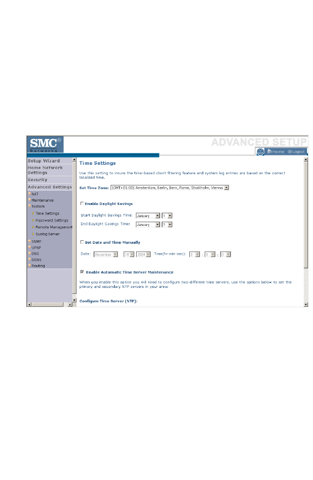
S
YSTEM
4-69
System
This section includes all the basic configuration tools for the
BARRICADE, such as time settings, password settings, and remote
management.
Time Settings
Set the time zone and time server for the BARRICADE. This information
is used for log entries and client access control.
• Set Time Zone
Select your time zone from the drop-down list
• Enable Daylight Savings
Check Enable Daylight Savings, and set the start and end dates if
your area requires daylight savings.
• Set Date and Time Manually
For manually setting the date and time, configure the date and time by
selecting the options from the drop-down list.
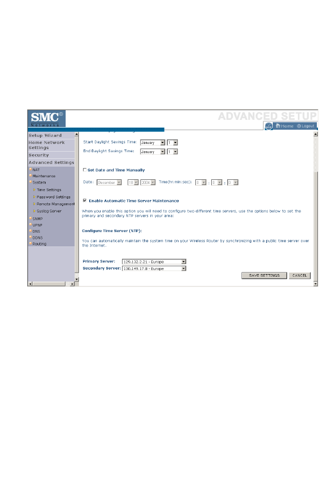
C
ONFIGURING
THE
BARRICADE
4-70
• Enable Automatic Time Server Maintenance
Check Enable Automatic Time Server Maintenance to
automatically maintain the BARRICADE’s system time by
synchronizing with a public time server over the Internet.
• Configure Time Server (NTP):
Configure two different time servers by selecting the options in the
Primary Server and Secondary Server fields.
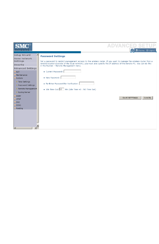
S
YSTEM
4-71
Password Settings
Use this page to restrict access based on a password. For security you
should assign one before exposing the BARRICADE to the Internet.
Passwords can contain from 3 to12 alphanumeric characters and are case
sensitive.
Note: If your password is lost, or you cannot gain access to the user
interface, press the Reset button (colored blue) on the rear panel
(holding it down for at least six seconds) to restore the factory
defaults. The default password is “smcadmin”.
Enter a maximum Idle Time Out (in minutes) to define a maximum period
of time an inactive login session will be maintained. If the connection is
inactive for longer than the maximum idle time, it will be logged out, and
you will have to log in to the web management system again. Setting the
idle time to 0, will mean the connection never times out.
(Default: 10 minutes)
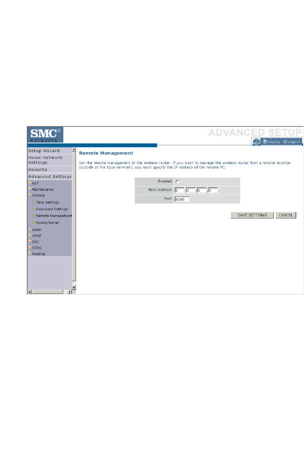
C
ONFIGURING
THE
BARRICADE
4-72
Remote Management
By default, management access is only available to users on your local
network. However, you can also manage the BARRICADE from a remote
host by entering the IP address of a remote computer on this screen.
Check the Enabled check box, and enter the IP address of the remote
host and click Save Settings.
Note: If you check Enabled and specify an IP address of 0.0.0.0, any
host can manage the BARRICADE.
For remote management via WAN IP address you need to connect using
port 8080. Simply enter WAN IP address followed by :8080 in the address
field of your web browser, for example, 212.120.68.20:8080.
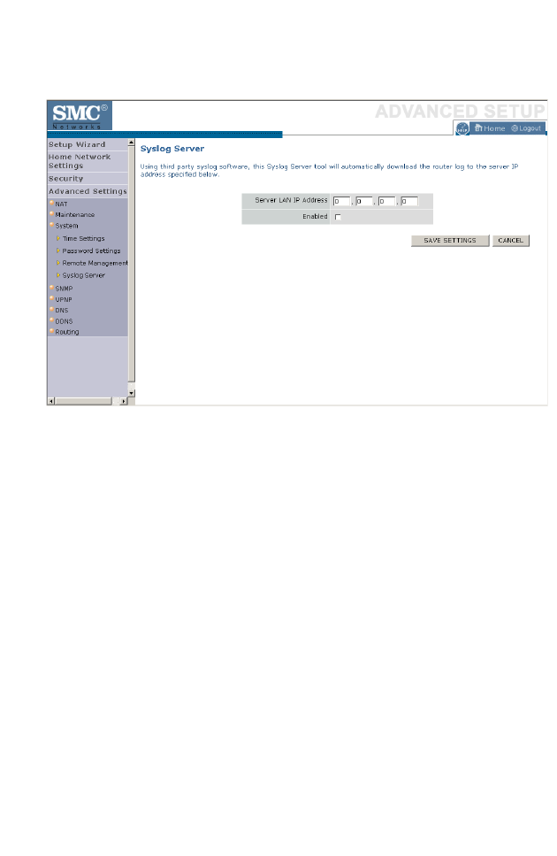
S
YSTEM
4-73
Syslog Server
The Syslog Server downloads the BARRICADE log file to the server with
the IP address specified on this screen. Syslog servers offer the possibility
to capture the live logs of the router on a PC. There are many shareware
syslogs servers available on the web. (Default: Disabled)
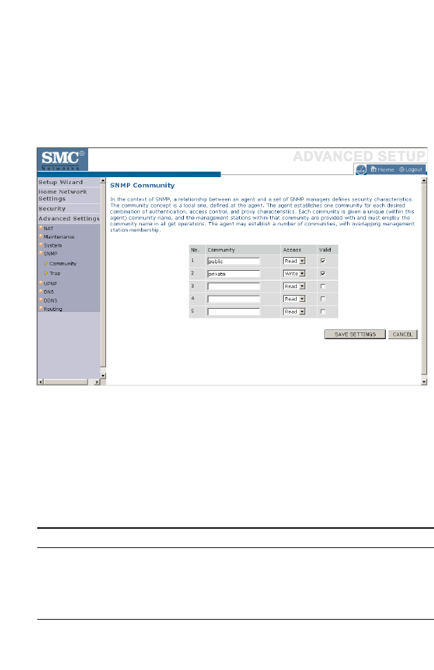
C
ONFIGURING
THE
BARRICADE
4-74
SNMP
Community
Click SNMP and then Community to access the screen below.
Use the SNMP configuration screen to display and modify parameters for
the Simple Network Management Protocol (SNMP). A computer attached
to the network, called a Network Management Station (NMS), can be used
to access this information. Access rights to the agent are controlled by
community strings. To communicate with the BARRICADE, the NMS
must first submit a valid community string for authentication.
Note: Up to 5 community names may be entered.
Parameter Description
Community A community name authorized for management access.
Access Management access is restricted to Read Only (Read) or
Read/Write (Write).
Valid Enables/disables the entry.
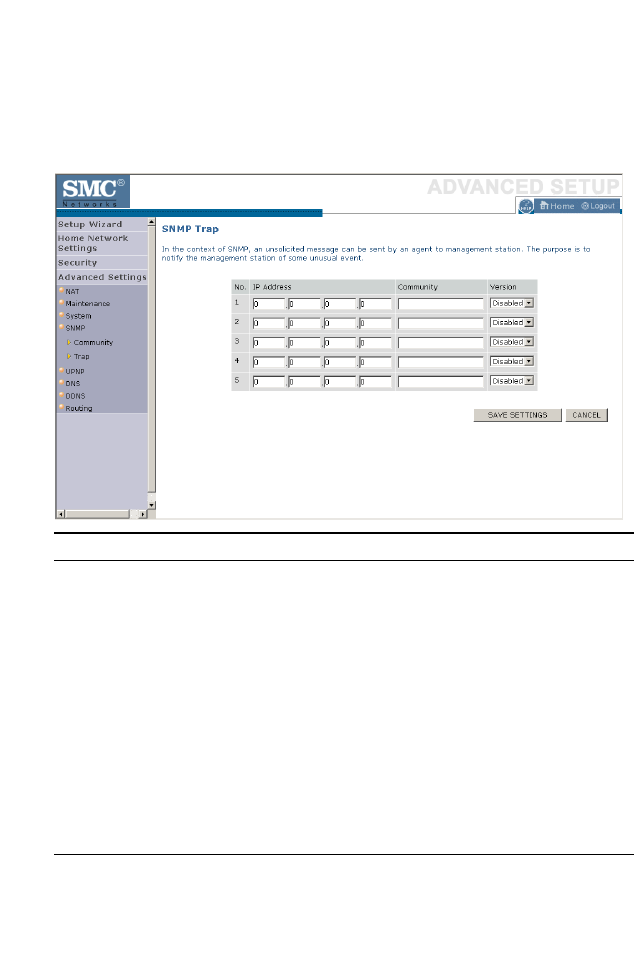
SNMP
4-75
Trap
Click SNMP and then Trap. This will load the SNMP trap screen shown
below.
Click Save Settings to proceed, or Cancel to change your settings.
Parameter Description
IP Address Traps are sent to this address when errors or specific events
occur on the network.
Community A community string (password) specified for trap
management. Enter a word, something other than public or
private, to prevent unauthorized individuals from reading
information on your system.
Version Sets the trap status to disabled, or enabled with v1 or v2c.
The v2c protocol was proposed in late 1995 and includes
enhancements to v1 that are universally accepted. These
include a get-bulk command to reduce network
management traffic when retrieving a sequence of MIB
variables, and a more elaborate set of error codes for
improved reporting to a Network Management Station.
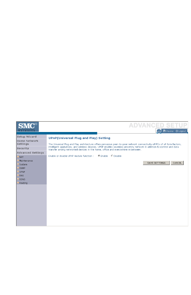
C
ONFIGURING
THE
BARRICADE
4-76
UPNP
Universal Plug and Play technology makes home networking simple and
affordable. This architecture offers pervasive peer-to-peer network
connectivity of PCs of all form factors, intelligent appliances, and wireless
devices. UPnP architecture leverages TCP/IP and the web to enable
seamless proximity networking in addition to control and data transfer
among networked devices in the home, office, and everywhere in between.
Click Enable to turn on the Universal Plug and Play function of the
BARRICADE. This function allows the device to automatically and
dynamically join a network.
Click Save Settings to proceed, or Cancel to change your settings.
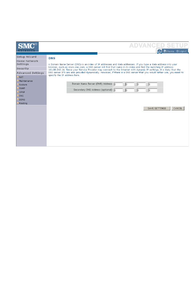
DNS (D
OMAIN
N
AME
S
ERVER
)
4-77
DNS (Domain Name Server)
Domain Name Servers are used to map a domain name
(e.g., www.somesite.com) to the equivalent numerical IP address
(e.g., 64.147.25.20). Your ISP should provide the IP address of one or
more Domain Name Servers. Enter those addresses on this page.
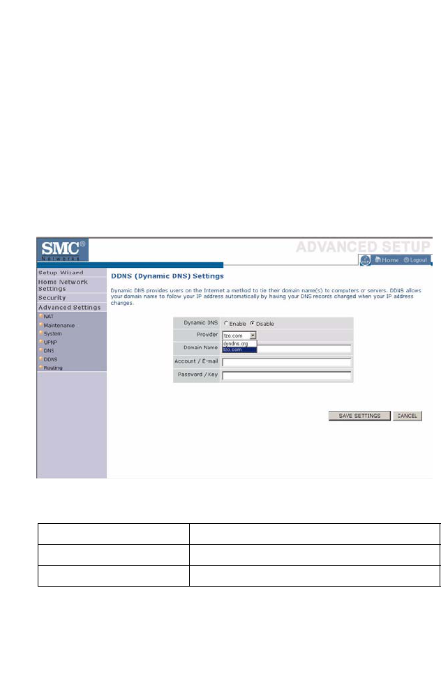
C
ONFIGURING
THE
BARRICADE
4-78
DDNS (Dynamic DNS)
Dynamic DNS (DDNS) provides users on the Internet with a method to
tie their domain name to the router or server. DDNS allows your domain
name to follow your IP address automatically by having your DNS records
changed when your IP address changes. (Default: Disabled)
The DDNS service dynamically updates DNS information to a static
hostname, provided by the DDNS service provider, as clients’ IP
addresses change.
Note: Please visit the web sites of the DDNS providers for details.
For using DDNS, click on the enable radio button, select the DDNS
Service type, and then enter the Domain Name, Account/E-mail address,
and Password/Key.
DDNS Service Provider Web Site
DynDNS.org http://www.dyndns.org
TZO.com http://www.tzo.com
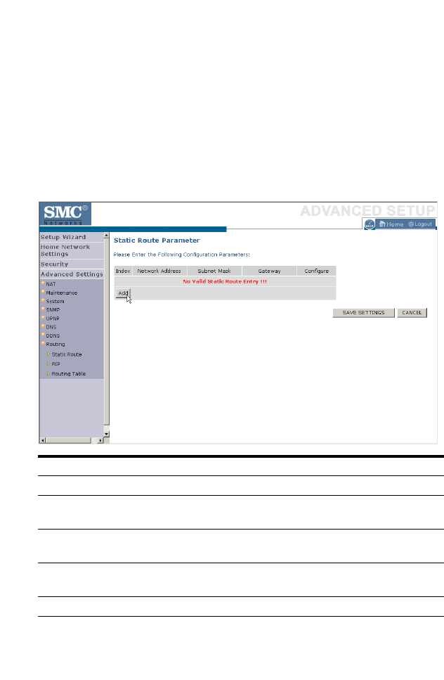
R
OUTING
4-79
Routing
This section defines routing related parameters, including static routes and
RIP (Routing Information Protocol) parameters.
Static Route
Click Add to add a new static route to the list.
Click Save Settings to save the configuration.
Parameter Description
Index Index number of the route.
Network Address Enter the IP address of the remote computer for which to set
a static route.
Subnet Mask Enter the subnet mask of the remote network for which to set
a static route.
Gateway Enter the WAN IP address of the gateway to the remote
network.
Configure Allows you to edit existing routes.
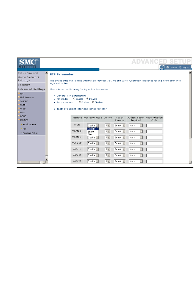
C
ONFIGURING
THE
BARRICADE
4-80
RIP
RIP sends routing-update messages at regular intervals and when the
network topology changes.
Parameter Description
General RIP
Parameters
RIP mode Globally enables or disables RIP.
Auto summary If Auto summary is disabled, then RIP packets will include
sub-network information from all subnetworks connected to
the router. If enabled, this sub-network information will be
summarized to one piece of information covering all
subnetworks.
Table of current
Interface RIP
parameter
Interface The WAN interface to be configured.
Operation Mode Disable: RIP disabled on this interface.
Enable: RIP enabled on this interface.
Silent: Listens for route broadcasts and updates its route table.
It does not participate in sending route broadcasts.

R
OUTING
4-81
When a router receives a routing update that includes changes to an entry,
it updates its routing table to reflect the new route. RIP routers maintain
only the best route to a destination. After updating its routing table, the
router immediately begins transmitting routing updates to inform other
network routers of the change.
Click Save Settings to proceed, or Cancel to change your settings.
Version Sets the RIP (Routing Information Protocol) version to use on
this interface.
Poison Reverse A method for preventing loops that would cause endless
retransmission of data traffic.
Authentication
Required None: No authentication.
Password: A password authentication key is included in the
packet. If this does not match what is expected, the packet will
be discarded. This method provides very little security as it is
possible to learn the authentication key by watching RIP
packets.
Authentication
Code Password Authentication key.
Parameter Description
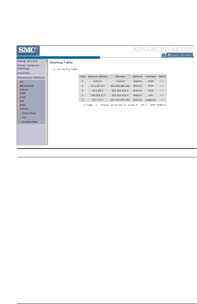
C
ONFIGURING
THE
BARRICADE
4-82
Routing Table
Click Routing Table to view the screen below.
Parameter Description
Flags Indicates the route status:
C = Direct connection on the same subnet.
S = Static route.
R = RIP (Routing Information Protocol) assigned route.
I = ICMP (Internet Control Message Protocol) Redirect route.
Network Address Destination IP address.
Netmask The subnetwork associated with the destination.
This is a template that identifies the address bits in the
destination address used for routing to specific subnets. Each
bit that corresponds to a “1” is part of the subnet mask
number; each bit that corresponds to “0” is part of the host
number.
Gateway The IP address of the router at the next hop to which frames
are forwarded.
Interface The local interface through which the next hop of this route is
reached.
Metric When a router receives a routing update that contains a new or
changed destination network entry, the router adds 1 to the
metric value indicated in the update and enters the network in
the routing table.

A-1
A
PPENDIX
A
T
ROUBLESHOOTING
This section describes common problems you may encounter and possible
solutions to them. The BARRICADE can be easily monitored through
panel indicators to identify problems.
Troubleshooting Chart
Symptom Action
LED Indicators
Power LED is
off
• Check connections between the BARRICADE, the
external power supply, and the wall outlet.
• If the power indicator does not turn on when the
power cord is plugged in, you may have a problem
with the power outlet, power cord, or external power
supply. However, if the unit powers off after running
for a while, check for loose power connections, power
losses, or surges at the power outlet. If you still cannot
isolate the problem, then the external power supply
may be defective. In this case, contact Technical
Support for assistance.

T
ROUBLESHOOTING
A-2
LED Indicators
LAN LED is
Off
• Verify that the BARRICADE and attached device are
powered on.
• Be sure the cable is plugged into both the
BARRICADE and the corresponding device.
• Verify that the proper cable type is used and that its
length does not exceed the specified limits.
• Be sure that the network interface on the attached
device is configured for the proper communication
speed and duplex mode.
• Check the adapter on the attached device and cable
connections for possible defects. Replace any
defective adapter or cable if necessary.
Network Connection Problems
Cannot ping the
BARRICADE
from the
attached LAN,
or the
BARRICADE
cannot ping any
device on the
attached LAN
• Verify that the IP addresses are properly configured.
For most applications, you should use the
BARRICADE’s DHCP function to dynamically
assign IP addresses to hosts on the attached LAN.
However, if you manually configure IP addresses on
the LAN, verify that the same network address
(network component of the IP address) and subnet
mask are used for both the BARRICADE and any
attached LAN devices.
• Be sure the device you want to ping (or from which
you are pinging) has been configured for TCP/IP.
Troubleshooting Chart
Symptom Action

T
ROUBLESHOOTING
A-3
Management Problems
Cannot connect
using the web
browser
• Be sure to have configured the BARRICADE with a
valid IP address, subnet mask, and default gateway.
• Check that you have a valid network connection to the
BARRICADE and that the port you are using has not
been disabled.
• Check the network cabling between the management
station and the BARRICADE.
Forgot or lost
the password
•Press the Reset button on the rear panel (holding it
down for at least six seconds) to restore the factory
defaults.
Troubleshooting Chart
Symptom Action

T
ROUBLESHOOTING
A-4
Wireless Problems
A wireless PC
cannot associate
with the
BARRICADE.
• Make sure the wireless PC has the same SSID settings
as the BARRICADE.
See “Channel and SSID” on page 4-28.
• You need to have the same security settings on the
clients and the BARRICADE. See “Security” on page
4-32.
The wireless
network is often
interrupted.
• Move your wireless PC closer to the BARRICADE to
find a better signal. If the signal is still weak, change
the angle of the antenna.
• There may be interference, possibly caused by
microwave ovens or wireless phones. Change the
location of the possible sources of interference or
change the location of the BARRICADE.
• Change the wireless channel on the BARRICADE.
See “Channel and SSID” on page 4-28.
• Check that the antenna, connectors, and cabling are
firmly connected.
The
BARRICADE
cannot be
detected by a
wireless client.
• The distance between the BARRICADE and wireless
PC is too great.
• Make sure the wireless PC has the same SSID and
security settings as the BARRICADE. See “Channel
and SSID” on page 4-28 and “Security” on page 4-32.
Troubleshooting Chart
Symptom Action

B-1
A
PPENDIX
B
C
ABLES
Ethernet Cable
Caution:
Do not plug a phone jack connector into an RJ-45 port.
For
Ethernet connections, use only twisted-pair cables with RJ-45
connectors that conform to FCC standards.
Specifications
Wiring Conventions
For Ethernet connections, a twisted-pair cable must have two pairs of
wires. Each wire pair is identified by two different colors. For example, one
wire might be red and the other, red with white stripes. Also, an RJ-45
connector must be attached to both ends of the cable.
Cable Types and Specifications
Cable Type Max. Length Connector
10BASE-T Cat. 3, 4, 5 100-ohm UTP 100 m (328 ft) RJ-45
100BASE-TX Cat. 5 100-ohm UTP 100 m (328 ft) RJ-45

C
ABLES
B-2
Each wire pair must be attached to the RJ-45 connectors in a specific
orientation. The following figure illustrates how the pins on an Ethernet
RJ-45 connector are numbered. Be sure to hold the connectors in the same
orientation when attaching the wires to the pins.
Figure B-1. RJ-45 Ethernet Connector Pin Numbers
RJ-45 Port Ethernet Connection
Use the straight-through CAT -5 Ethernet cable provided in the package
to connect the BARRICADE to your PC. When connecting to other
network devices such as an Ethernet switch, use the cable type shown in
the following table.
Attached Device Port Type Connecting Cable Type
MDI-X Straight-through
MDI Crossover

RJ-45 P
ORT
E
THERNET
C
ONNECTION
B-3
Pin Assignments
With 10BASE-T/100BASE-TX cable, pins 1 and 2 are used for
transmitting data, and pins 3 and 6 for receiving data.
Straight-Through Wiring
If the port on the attached device has internal crossover wiring (MDI-X),
then use straight-through cable.
RJ-45 Pin Assignments
Pin Number Assignment*
1Tx+
2Tx-
3Rx+
6Rx-
* The “+” and “-” signs represent the polarity of the
wires that make up each wire pair.
Straight-Through Cable Pin Assignments
End 1 End 2
1 (Tx+) 1 (Tx+)
2 (Tx-) 2 (Tx-)
3 (Rx+) 3 (Rx+)
6 (Rx-) 6 (Rx-)

C
ABLES
B-4
Crossover Wiring
If the port on the attached device has straight-through wiring (MDI), use
crossover cable.
Crossover Cable Pin Assignments
End 1 End 2
1 (Tx+) 3 (Rx+)
2 (Tx-) 6 (Rx-)
3 (Rx+) 1 (Tx+)
6 (Rx-) 2 (Tx-)

C-1
A
PPENDIX
C
S
PECIFICATIONS
IEEE Standards
IEEE 802.3 10 BASE-T Ethernet
IEEE 802.3u 100 BASE-TX Fast Ethernet
IEEE 802.3, 802.3u, 802.11g, 802.1D
ITU G.dmt
ITU G.Handshake
ITU T.413 issue 2 - ADSL full rate
LAN Interface
4 RJ-45 10 BASE-T/100 BASE-TX ports
Auto-negotiates the connection speed to 10 Mbps Ethernet or 100 Mbps
Fast Ethernet, and the transmission mode to half-duplex or full-duplex
WAN Interface
1 ADSL RJ-45 port
Indicator Panel
LAN 1~4, WLAN, PPPoE/DSL, WAN, Power
Dimensions
145 x 95 x 36 mm (5.70 x 3.74 x 1.41 in)
Weight
0.175 kg (0.469 lbs)
Input Power
9 V 1 A
DVE EU DV-91AUP, US DV-91A
Leader EU 48090100-C5, US 480910OO3CT
Power Consumption
8 Watts maximum

S
PECIFICATIONS
C-2
Advanced Features
Dynamic IP Address Configuration – DHCP, DNS
Firewall – Client privileges, hacker prevention and logging,
Stateful Packet Inspection
Virtual Private Network – PPTP, IPSec pass-through, VPN pass-through,
VLAN Ping
Internet Standards
RFC 826 ARP, RFC 791 IP, RFC 792 ICMP, RFC 768 UDP, RFC 793 TCP,
RFC 783 TFTP, RFC 1483 AAL5 Encapsulation, RFC 1661 PPP,
RFC 1866 HTML, RFC 2068 HTTP, RFC 2364 PPP over ATM
Radio Features
Wireless RF module Frequency Band
802.11g Radio: 2.4GHz
802.11b Radio: 2.4GHz
USA - FCC
2412~2462MHz (Ch1~Ch11)
Canada - IC
2412~2462MHz (Ch1~Ch11)
Europe - ETSI
2412~2472MHz (Ch1~Ch13)
Japan - STD-T66/STD-33
2412~2484MHz (Ch1~Ch14)
Modulation Type
OFDM, CCK
Operating Channels IEEE 802.11b Compliant:
11 channels (US, Canada)
13 channels (ETSI)
14 channels (Japan)
Operating Channels IEEE 802.11g Compliant:
13 channels (US, Canada, Europe, Japan)

S
PECIFICATIONS
C-3
RF Output Power Modulation Rate-Output Power (dBm)
802.11b - 1Mbps 17
802.11b - 2Mbps 17
802.11b - 5.5Mbps 17
802.11b - 11Mbps 17
Modulation Rate-Output Power (dBm)
802.11g - 6Mbps 16
802.11g - 9Mbps 16
802.11g - 12Mbps 16
802.11g - 18Mbps 16
802.11g- 24Mbps 16
802.11g - 36Mbps 16
802.11g- 48Mbps 14
802.11g - 54Mbps 12
Standards Compliance
Safety
TÜV
Environmental
CE Mark
Temperature
Operating 0 to 40 °C (32 to 104 °F)
Storage -40 to 70 °C (-40 to 158 °F)
Humidity
5% to 95% (non-condensing)
Vibration
IEC 68-2-36, IEC 68-2-6
Shock
IEC 68-2-29
Drop
IEC 68-2-32

S
PECIFICATIONS
C-4