Arcadyan Technology WG6005AARC EZ-Stream Universal 2.4GHz/5GHz Cable/DSL Router User Manual
Arcadyan Technology Corporation EZ-Stream Universal 2.4GHz/5GHz Cable/DSL Router
User Manual


38 Tesla
Irvine, CA 92618
Phone: (949) 679-8000
EZ-Stream Universal 2.4GHz/5GHz
Wireless Cable/DSL Broadband Router
User Guide
From SMC’s EZ-Stream line of Broadband Routers
October 2003
Revision No: R01

COPYRIGHT
Information furnished by SMC Networks, Inc. (SMC) is believed to be accurate and reliable.
However, no responsibility is assumed by SMC for its use, nor for any infringements of patents
or other rights of third parties which may result from its use. No license is granted by
implication or otherwise under any patent or patent rights of SMC. SMC reserves the right to
change specifications at any time without notice.
Copyright © 2003 by
SMC Networks, Inc.
38 Tesla
Irvine, CA 92618
All rights reserved.
Trademarks:
SMC is a registered trademark; EZ-Stream and Barricade is a trademark of SMC Networks,
Inc. Other product and company names are trademarks or registered trademarks of their
respective holders.

i
COMPLIANCES
Federal Communication Commission Interference
Statement
This equipment has been tested and found to comply with the limits for a Class B
digital device, pursuant to Part 15 of the FCC Rules. These limits are designed to
provide reasonable protection against harmful interference in a residential
installation. This equipment generates, uses and can radiate radio frequency
energy and, if not installed and used in accordance with the instructions, may
cause harmful interference to radio communications. However, there is no
guarantee that interference will not occur in a particular installation. If this
equipment does cause harmful interference to radio or television reception, which
can be determined by turning the equipment off and on, the user is encouraged to
try to correct the interference by one of the following measures:
• Reorient or relocate the receiving antenna
• Increase the separation between the equipment and receiver
• Connect the equipment into an outlet on a circuit different from that to which the
receiver is connected
• Consult the dealer or an experienced radio/TV technician for help
This device complies with Part 15 of the FCC Rules. Operation is subject to the
following two conditions: (1) This device may not cause harmful interference, and
(2) this device must accept any interference received, including interference that
may cause undesired operation.
FCC Caution: Any changes or modifications not expressly approved by the party
responsible for compliance could void the user's authority to operate this
equipment.
IMPORTANT NOTE:
FCC Radiation Exposure Statement
This equipment complies with FCC radiation exposure limits set forth for an
uncontrolled environment. This equipment should be installed and operated with a
minimum distance of 20 centimeters (8 inches) between the radiator and your
body. This transmitter must not be co-located or operating in conjunction with any
other antenna or transmitter.

Compliances
ii
EC Conformance Declaration - Class B
SMC contact for these products in Europe is:
SMC Networks Europe,
Edificio Conata II,
Calle Fructuós Gelabert 6-8, 2o, 4a,
08970 - Sant Joan Despí,
Barcelona, Spain.
This information technology equipment complies with the requirements of the
Council Directive 89/336/EEC on the Approximation of the laws of the Member
States relating to Electromagnetic Compatibility and 73/23/EEC for electrical
equipment used within certain voltage limits and the Amendment Directive 93/68/
EEC. For the evaluation of the compliance with these Directives, the following
standards were applied:
RFI
Emission:
* Limit class B according to EN 55022:1998
* Limit class B for harmonic current emission according to EN 61000-3-2/
1995
* Limitation of voltage fluctuation and flicker in low-voltage supply system
according to EN 61000-3-3/1995
Immunity: * Product family standard according to EN 55024:1998
* Electrostatic Discharge according to EN 61000-4-2:1995
(Contact Discharge: ±4 kV, Air Discharge: ±8 kV)
* Radio-frequency electromagnetic field according to EN 61000-4-3: 1996
(80 - 1000 MHz with 1 kHz AM 80% Modulation: 3 V/m)
* Electrical fast transient/burst according to EN 61000-4-4:1995 (AC/DC
power supply: ±1 kV, Data/Signal lines: ±0.5 kV)
* Surge immunity test according to EN 61000-4-5:1995 (AC/DC Line to Line:
±1 kV, AC/DC Line to Earth: ±2 kV)
* Immunity to conducted disturbances, Induced by radio-frequency fields: EN
61000-4-6:1996(0.15 - 80 MHz with 1 kHz AM 80% Modulation:
3V/m)
* Power frequency magnetic field immunity test according to EN
61000-4-8:1993(1 A/m at frequency 50 Hz)
* Voltage dips, short interruptions and voltage variations immunity test
according to EN 61000-4-11:1994 (>95% Reduction @10 ms, 30%
Reduction @500 ms, >95% Reduction @5000 ms)
LVD: * EN60950 (A1/1992; A2/1993; A3/1993; A4/1995; A11/1997)
MDD:*IEC 60601-1

Compliances
iii
Industry Canada - Class B
This digital apparatus does not exceed the Class B limits for radio noise emissions
from digital apparatus as set out in the interference-causing equipment standard
entitled “Digital Apparatus,” ICES-003 of the Department of Communications.
Cet appareil numérique respecte les limites de bruits radioélectriques applicables
aux appareils numériques de Classe B prescrites dans la norme sur le matériel
brouilleur: “Appareils Numériques,” NMB-003 édictée par le ministère des
Communications.
Safety Compliance
Underwriters Laboratories Compliance Statement
Important! Before making connections, make sure you have the correct cord set.
Check it (read the label on the cable) against the following:
The unit automatically matches the connected input voltage. Therefore, no
additional adjustments are necessary when connecting it to any input voltage
within the range marked on the rear panel.
Operating Voltage Cord Set Specifications
120 Volts UL Listed/CSA Certified Cord Set
Minimum 18 AWG
Type SVT or SJT three conductor cord
Maximum length of 15 feet
Parallel blade, grounding type attachment plug
rated 15 A, 125 V
240 Volts (Europe only) Cord Set with H05VV-F cord having three
conductors with minimum diameter of 0.75 mm2
IEC-320 receptacle
Male plug rated 10 A, 250 V

Compliances
iv

v
T
ABLE OF
C
ONTENTS
About the Wireless Barricade Router . . . . . . . . . . 1
LED Indicators . . . . . . . . . . . . . . . . . . . . . . . . . . . . . . . . . . . . . . 1
Features and Benefits . . . . . . . . . . . . . . . . . . . . . . . . . . . . . . . . 2
Installing the Wireless Barricade Router . . . . . . . 3
Package Contents . . . . . . . . . . . . . . . . . . . . . . . . . . . . . . . . . . . 3
Hardware Description . . . . . . . . . . . . . . . . . . . . . . . . . . . . . . . . . 4
System Requirements . . . . . . . . . . . . . . . . . . . . . . . . . . . . . . . . 6
Connect the System . . . . . . . . . . . . . . . . . . . . . . . . . . . . . . . . . . 6
Basic Installation Procedure . . . . . . . . . . . . . . . . . . . . . . . 7
Configuring Client TCP/IP . . . . . . . . . . . . . . . . . . 12
Installing TCP/IP . . . . . . . . . . . . . . . . . . . . . . . . . . . . . . . . . . . . 12
Windows 95/98/Me . . . . . . . . . . . . . . . . . . . . . . . . . . . . . 12
Windows 2000 . . . . . . . . . . . . . . . . . . . . . . . . . . . . . . . . 13
Setting Up TCP/IP . . . . . . . . . . . . . . . . . . . . . . . . . . . . . . . . . . 15
Configuring Your Computer in Windows 95/98/Me . . . . . 15
Configuring Your Computer in Windows NT 4.0 . . . . . . . 18
Configuring Your Computer in Windows 2000 . . . . . . . . 20
Configuring Your Computer in Windows XP . . . . . . . . . . 21
Configuring a Macintosh Computer . . . . . . . . . . . . . . . . 22
Manual IP Configuration (for all Windows OS) . . . . . . . . 23
Verifying Your TCP/IP Connection . . . . . . . . . . . . . . . . . 25
Configuring the Wireless Barricade Router . . . . 26
Browser Configuration . . . . . . . . . . . . . . . . . . . . . . . . . . . . . . . 26
Disable Proxy Connection . . . . . . . . . . . . . . . . . . . . . . . 27
Navigating the Web Browser Interface . . . . . . . . . . . . . . . . . . . 27
Making Configuration Changes . . . . . . . . . . . . . . . . . . . 28
SETUP WIZARD . . . . . . . . . . . . . . . . . . . . . . . . . . . . . . . . . . . 29
Time Zone . . . . . . . . . . . . . . . . . . . . . . . . . . . . . . . . . . . . 29
Broadband Type . . . . . . . . . . . . . . . . . . . . . . . . . . . . . . . 30
Advanced Setup . . . . . . . . . . . . . . . . . . . . . . . . . . . . . . . . . . . . 33
SYSTEM . . . . . . . . . . . . . . . . . . . . . . . . . . . . . . . . . . . . . 35
WAN . . . . . . . . . . . . . . . . . . . . . . . . . . . . . . . . . . . . . . . . 38

T
ABLE OF
C
ONTENTS
vi
LAN . . . . . . . . . . . . . . . . . . . . . . . . . . . . . . . . . . . . . . . . 44
WIRELESS . . . . . . . . . . . . . . . . . . . . . . . . . . . . . . . . . . . 45
NAT . . . . . . . . . . . . . . . . . . . . . . . . . . . . . . . . . . . . . . . . 52
FIREWALL . . . . . . . . . . . . . . . . . . . . . . . . . . . . . . . . . . . 56
DDNS . . . . . . . . . . . . . . . . . . . . . . . . . . . . . . . . . . . . . . . 68
UPnP . . . . . . . . . . . . . . . . . . . . . . . . . . . . . . . . . . . . . . . 69
TOOLS . . . . . . . . . . . . . . . . . . . . . . . . . . . . . . . . . . . . . . 70
STATUS . . . . . . . . . . . . . . . . . . . . . . . . . . . . . . . . . . . . . 73
Troubleshooting . . . . . . . . . . . . . . . . . . . . . . . . . .74
Specifications . . . . . . . . . . . . . . . . . . . . . . . . . . . .77
1
ABOUT THE WIRELESS
BARRICADE ROUTER
Congratulations on your purchase of the 2.4GHz/5GHz Wireless
Barricade™ Broadband Router. SMC is proud to provide you
with a powerful yet simple communication device for connecting
your local area network (LAN) to the Internet.
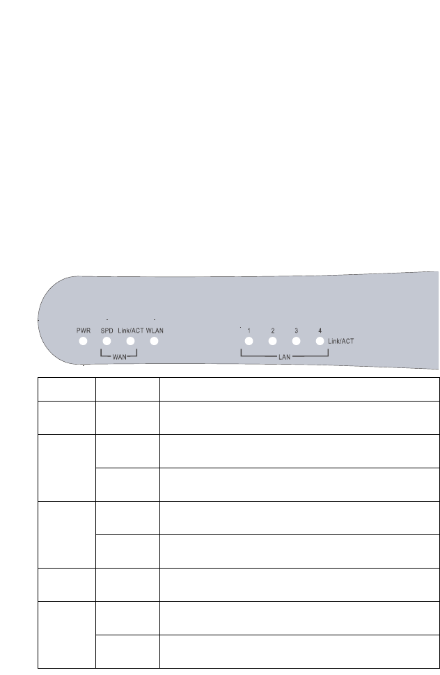
LED Indicators
The Wireless Barricade Router includes status LED indicators,
as described in the following figure and table.
LED Status Description
PWR
(Green)
On The Wireless Barricade Router is receiving power.
SPD
(Green)
Off The indicated LAN port has established a valid 10 Mbps
network connection.
On The indicated LAN port has established a valid
100 Mbps network connection.
Link/ACT
(Green)
On The indicated LAN port has established a valid network
connection.
Flashing The indicated LAN port is transmitting or receiving
traffic.
WLAN
(Green)
The Wireless Barricade Router has established a valid
wireless connection.
1, 2, 3, 4
(Green)
On The indicated LAN port has established a valid network
connection.
Flashing The indicated LAN port is transmitting or receiving
traffic.

About the Wireless Barricade Router
2
Features and Benefits
•Internet connection to DSL or cable modem via
a 10/100 Mbps WAN port
•Local network connection via 10/100 Mbps Ethernet ports or
108 Mbps wireless interface (supporting up to 253 mobile
users)
•802.11a/b/g compliant – interoperable with multiple vendors
•Advanced security through 64/128-bit WEP encryption,
802.1x, SSID broadcast disabled, and MAC address filtering
features to protect your sensitive data and authenticate only
authorized users to your network
•Provides seamless roaming within 802.11a/b/g WLAN
environment
•DHCP for dynamic IP configuration, and DNS for domain
name mapping
•Firewall with Stateful Packet Inspection, client privileges,
hacker prevention, DoS, and NAT
•NAT also enables multi-user access with a single-user
account, and virtual server functionality (providing protected
access to Internet services such as web, mail, FTP, and
Telnet)
•Virtual Private Network support using PPTP, L2TP, or IPSec
pass-through
•User-definable application sensing tunnel supports
applications requiring multiple connections
•Parental controls allow the user to restrict web browsing
•Automatic E-mail alerts when the network is being attacked
•Easy setup through a web browser on any operating system
that supports TCP/IP
•Compatible with all popular Internet applications

3
INSTALLING THE WIRELESS
BARRICADE ROUTER
Before installing the 2.4GHz/5GHz Wireless Barricade
Broadband Router, verify that you have all the items listed under
“Package Contents.” If any of the items are missing or damaged,
contact your local SMC distributor. Also be sure that you have all
the necessary cabling before installing the Router. After installing
the Router, refer to the web-based configuration program in
“Configuring the Wireless Barricade Router” on page 26 for
information on configuring the Router.
Package Contents
After unpacking the Wireless Barricade Router, check the
contents of the box to be sure you have received the following
components:
•2.4GHz/5GHz Wireless Barricade Broadband Router
•Power adapter
•One CAT-5 Ethernet cable
•Four rubber feet
•Installation CD containing this User Guide and EZ 3-Click
Installation Wizard
•Quick Installation Guide
Immediately inform your dealer in the event of any incorrect,
missing or damaged parts. If possible, please retain the carton
and original packing materials in case there is a need to return
the product.
Please register on SMC’s web site at www.smc.com The
Wireless Barricade Router is covered by a limited lifetime
warranty.

Installing the Wireless Barricade Router
4
Hardware Description
The Router can be connected to the Internet or to a remote site
using its RJ-45 WAN port. It can be connected directly to your PC
or to a local area network using any of the Fast Ethernet LAN
ports.
Access speed to the Internet depends on your service type.
Full-rate ADSL can provide up to 8 Mbps downstream and
640 Kbps upstream. G.lite (or splitterless) ADSL provides up to
1.5 Mbps downstream and 512 Kbps upstream. Cable modems
can provide up to 36 Mbps downstream and 2 Mbps upstream.
ISDN can provide up to 128 Kbps when using two bearer
channels. PSTN analog connections can now run up to 56 Kbps.
However, you should note that the actual rate provided by
specific service providers may vary dramatically from these
upper limits.
Although access speed to the Internet is determined by the
modem type connected to the Router, data passing between
devices connected to your local area network can run up to
100 Mbps over the Fast Ethernet ports.
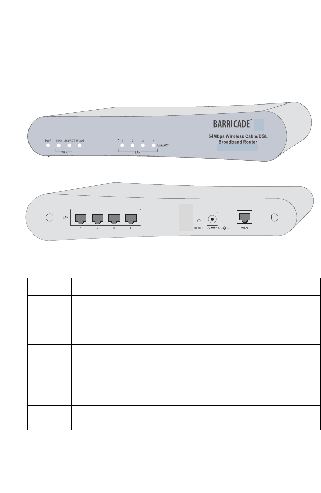
The Router includes an LED display on the front panel for system
power and port indications that simplifies installation and network
troubleshooting. It also provides four RJ-45 LAN ports and one
RJ-45 WAN port on the rear panel.
•4 RJ-45 ports for connection to a 10BASE-T/100BASE-TX
Ethernet Local Area Network (LAN). These ports can
auto-negotiate the operating speed to 10/100 Mbps, the mode
to half/full duplex, and the pin signals to MDI/MDI-X
(i.e., allowing these ports to be connected to any network
device with straight-through cable). These ports can be
connected directly to a PC or to a server equipped with an
Ethernet network interface card, or to a networking device
such as an Ethernet hub or switch.
Hardware Description
5
•One RJ-45 port for connection to a DSL or cable modem
(WAN). This port also auto-negotiates operating speed to
10/100 Mbps, the mode to half/full duplex, and the pin signals
to MDI/MDI-X.
The following figures show the components of the Router:
Figure 1. Front and Rear Panels
Item Description
LEDs PWR, SPD, Link/ACT, WLAN and LAN port status indicators.
(See “LED Indicators” on page 1.)
LAN
Ports
Use this port to connect to your PC.
Reset
Button
Use this button to reboot the router or restore the default factory
settings.
Power
Inlet
Connect the included power adapter to this inlet.
Warning: Using the wrong type of power adapter may damage
your router.
WAN
Port
Connect your ethernet cable, or xDSL modem to this port.

Installing the Wireless Barricade Router
6
System Requirements
You must have an ISP that meets the following minimum
requirements:
•Internet access from your local telephone company or Internet
Service Provider (ISP) using a DSL modem or cable modem.
•A PC using a fixed IP address or dynamic IP address
assigned via DHCP, as well as a Gateway server address and
DNS server address from your service provider.
•A computer equipped with a 10 Mbps, 100 Mbps, or
10/100 Mbps Fast Ethernet card, or a USB-to-Ethernet
converter.
•TCP/IP network protocol installed on each PC that needs to
access the Internet.
•A Java-enabled web browser, such as Microsoft Internet
Explorer 5.0 or above installed on one PC at your site for
configuring the Router.
Connect the System
The Router can be positioned at any convenient location in your
office or home. No special wiring or cooling requirements are
needed. You should, however comply with the following
guidelines:
•Keep the Router away from any heating devices.
•Do not place the Router in a dusty or wet environment.
You should also remember to turn off the power, remove the
power cord from the outlet, and keep your hands dry when you
install the Router.
Connect the System
7
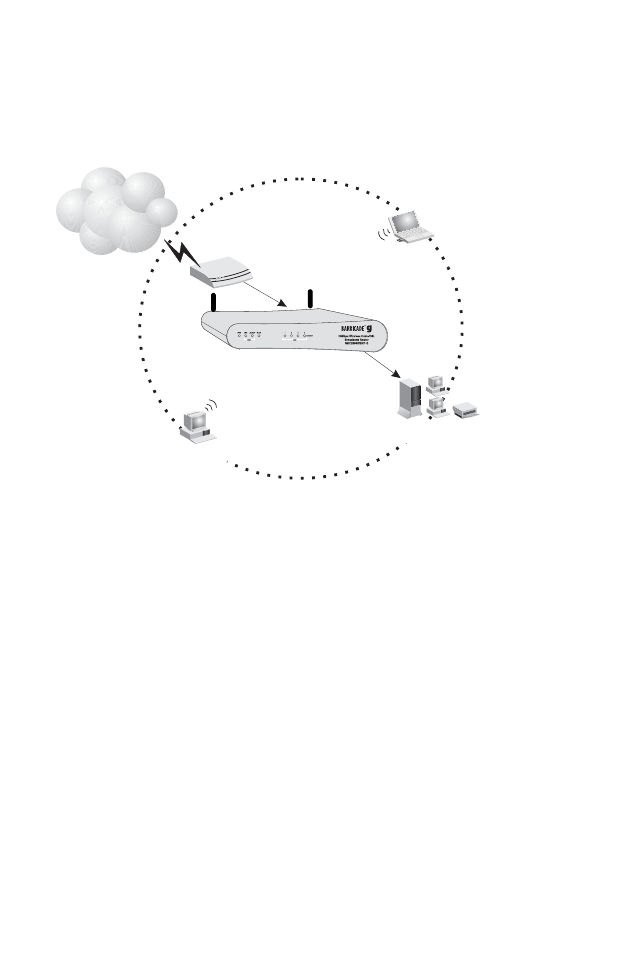
Basic Installation Procedure
1. Connect the LAN: Connect the Router to your PC, or to a
hub or switch. Run Ethernet cable from one of the LAN ports
on the rear of the Router to your computer’s network adapter
or to another network device.
You may also connect the Router to your PC (using a
wireless client adapter) via radio signals. Position both
antennas on the back of the Router into the desired positions.
For more effective coverage, position the antennas along
different axes. For example, try positioning the antennas
around 45 to 90 degrees apart. (The antennas emit signals
along the toroidal plane – and thus provide more
effective coverage when positioned along different
axes.)
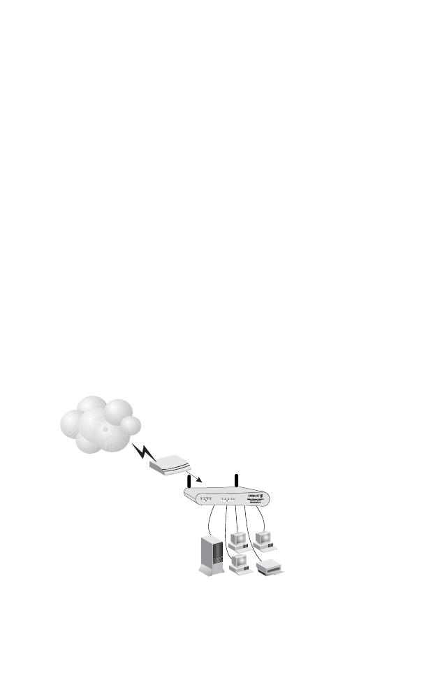
2. Connect the WAN: Prepare an Ethernet cable for connecting
the
Router to a cable/xDSL modem or Ethernet router.
3. Power on: Connect the power adapter to the Router.
Figure 2. Connecting the Wireless Barricade Router
Internet
Internet
Access
Device
SMC2804WBRP-G
Wireless Gateway
SOHO Office or Residence
Installing the Wireless Barricade Router
8
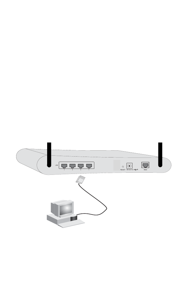
Attach to Your Network Using Ethernet Cabling
The four LAN ports on the Router auto-negotiate the connection
speed to 10 Mbps Ethernet or 100 Mbps Fast Ethernet, and the
transmission mode to half duplex or full duplex.
Use twisted-pair cable to connect any of the four LAN ports on
the Router to an Ethernet adapter on your PC. Otherwise, you
can cascade any of the LAN ports on the Router to an Ethernet
hub or switch, and then connect your PC or other network
equipment to the hub or switch. When inserting an RJ-45 plug,
be sure the tab on the plug clicks into position to ensure that it is
properly seated.
Warning: Do not plug a phone jack connector into any RJ-45
port. This may damage the Router. Instead, use only
twisted-pair cables with RJ-45 connectors that conform
with FCC standards.
Figure 3. Making the LAN Connections

Connect the System
9
Attach to Your Network Using Radio Signals
Install a wireless network adapter in each computer that will be
connected to the Internet or your local network via radio signals.
SMC currently offers several wireless network cards, including
the
SMC2802W and SMC2835W wireless cards.
Rotate both antennas on the back of the Router to the desired
position. For more effective coverage, position the antennas
around 45 to 90 degrees apart. Try to place the Router in a
position that is located in the center of
your wireless network.
Normally, the higher you place the antenna,
the better the
performance. Ensure that the Router’s location provides optimal
reception throughout your home or office.
Computers equipped with a wireless adapter can communicate
with each other as an independent wireless LAN by configuring
each computer to the same radio channel. However, the Router
can provide access to your wired/wireless LAN or to the Internet
for all wireless workstations. Each wireless PC in this network
infrastructure can talk to any computer in the wireless group via a
radio link, or access other computers or network resources in the
wired LAN infrastructure or over the Internet via the Router.
The wireless infrastructure configuration not only extends the
accessibility of wireless PCs to the wired LAN, but also increases
the effective wireless transmission range for wireless PCs by
retransmitting incoming radio signals through the Router.
Installing the Wireless Barricade Router
10
A wireless infrastructure can be used for access to a central
database, or for connection between mobile workers, as shown
in the following figure:
Figure 4. Making the WLAN Connections
Internet
Access
Device
SMC2804WBRP-G
Wireless Gateway
Notebook with Wireless
PC Card Adapter
PC with Wireless
PCI Adapter
Wired LAN
Wired to Wireless
Network Extension
Internet
Connect the System
11
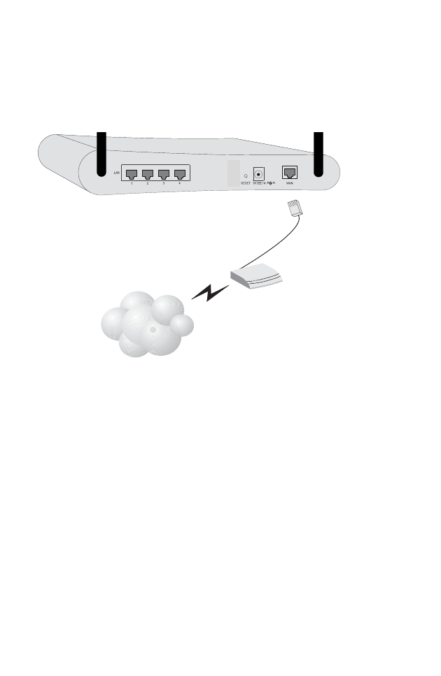
Attach the Wireless Barricade Router to the Internet
If Internet services are provided through an xDSL or cable
modem, use unshielded or shielded twisted-pair Ethernet cable
(Category 3 or greater) with RJ-45 plugs to connect the
broadband modem directly to the WAN port on the Router.
Figure 5. Making the WAN Connection
Note: When connecting to the WAN port, use 100-ohm
Category 3, 4, or 5 shielded or unshielded twisted-pair
cable with RJ-45 connectors at both ends for all
connections.
Connecting the Power Adapter
Plug the power adapter into the power socket on the Router, and
the other end into a power outlet. Check the indicator marked
“PWR” on the front panel to be sure it is on. If the power i
ndicator
does not light, refer to
“Troubleshooting” on page 74
.
ISP
(Primary)
DSL/Cable
Modem
12
CONFIGURING
CLIENT TCP/IP
If you have not previously installed the TCP/IP protocols on your
client PCs, refer to the following section. If you need information
on how to configure a TCP/IP address on a PC, refer to “Setting
Up TCP/IP” on page 15.
Installing TCP/IP
Windows 95/98/Me
1. Click Start/Settings/Control Panel.
2. Double-click the Network icon and select the Configuration
tab in the Network window.
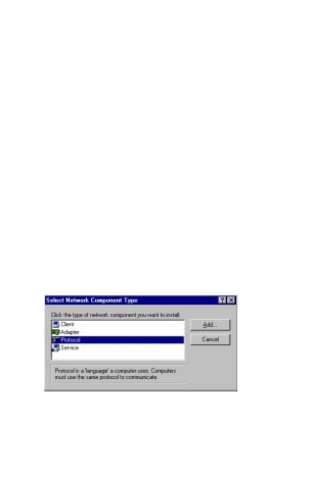
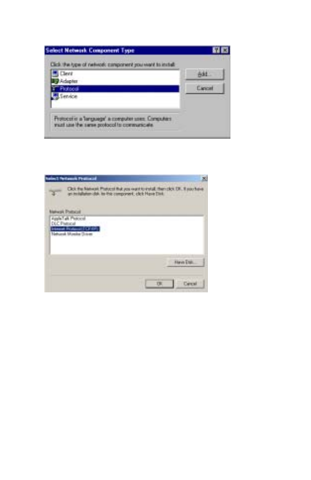
3. Click the Add button.
4. Double-click Protocol.
Installing TCP/IP
13
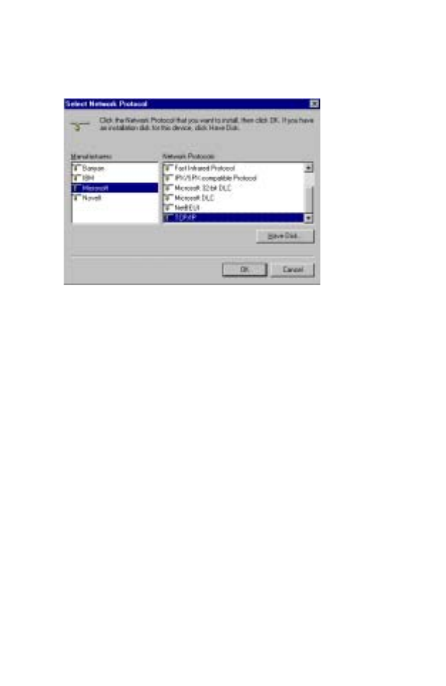
5. Select Microsoft in the manufacturers list. Select TCP/IP in
the Network Protocols list. Click the OK button to return to the
Network window.
6. The TCP/IP protocol will be listed in the Network window.
Click OK. The operating system may prompt you to restart
your system. Click Yes and the computer will shut down and
restart.
Windows 2000
1. Click the Start button and choose Settings, then click the
Network and Dial-up Connections icon.
2. Double-click the Local Area Connection icon, and click the
Properties button on the General tab.
3. Click the install... button.
Configuring Client TCP/IP
14
4. Double-click Protocol.
5. Choose Internet Protocol (TCP/IP). Click the OK button to
return to the Network window.
6. The TCP/IP protocol will be listed in the Network window.
Click OK to complete the installation procedure.

Setting Up TCP/IP
15
Setting Up TCP/IP
To access the Internet through the Router, you must configure
the network settings of the computers on your LAN to use the
same IP subnet as the Router. The default network settings for
the Router are:
Gateway IP Address: 192.168.2.1
Subnet Mask: 255.255.255.0
Note: These settings may be changed to suit your network
requirements, but you must first configure at least one
computer as described in this chapter to access the
Router’s web configuration interface. See “Configuring
the Wireless Barricade Router” on page 26 for
information on configuring the Router.)
If you have not previously configured TCP/IP for your computer,
refer to“Configuring Client TCP/IP” on page 12. The IP address
of the connected client PC should be 192.168.2.x (where x
means 2–254). You can set the IP address for client PCs either
by automatically obtaining an IP address from the Router’s
DHCP service or by manual configuration.
Configuring Your Computer in Windows 95/98/Me
You may find that the instructions here do not exactly match your
version of Windows. This is because these steps and
screenshots were created in Windows 98. Windows 95 and
Windows Millennium Edition are very similar, but not identical, to
Windows 98.
1. From the Windows desktop, click Start/Settings/Control
Panel.
2. In the Control Panel, locate and double-click the Network
icon.
Configuring Client TCP/IP
16
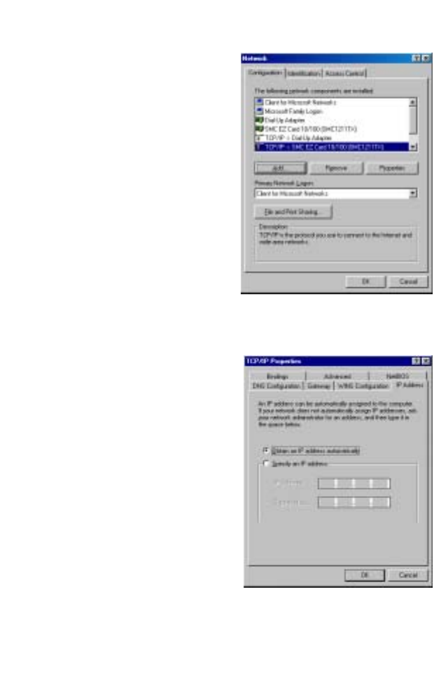
3. On the Network window
Configuration tab,
double-click the TCP/IP
entry for your network
card.
4. Click the IP Address tab.
5. Click the “Obtain an IP
address“ option.
6. Next click on the Gateway
tab and verify the Gateway
field is blank. If there are
IP addresses listed in the Gateway section, highlight each
one and click Remove until the section is empty.
7. Click the OK button to close the TCP/IP Properties window.
Setting Up TCP/IP
17
8. On the Network Properties Window, click the OK button to
save these new settings.
Note: Windows may ask you for the original Windows
installation disk or additional files. Check for the files at
c:\windows\options\cabs, or insert your Windows
CD-ROM into your CDROM drive and check the correct
file location, e.g., D:\win98, D:\win9x. (if D is the letter
of your CD-ROM drive).
9. Windows may prompt you to restart the PC. If so, click the Yes
button. If Windows does not prompt you to restart your
computer, do so to insure your settings.
Obtain IP Settings from Your Wireless Barricade Router
Now that you have configured your computer to connect to your
Router, it needs to obtain new network settings. By releasing old
IP settings and renewing them with settings from your Router,
you will also verify that you have configured your computer
correctly.
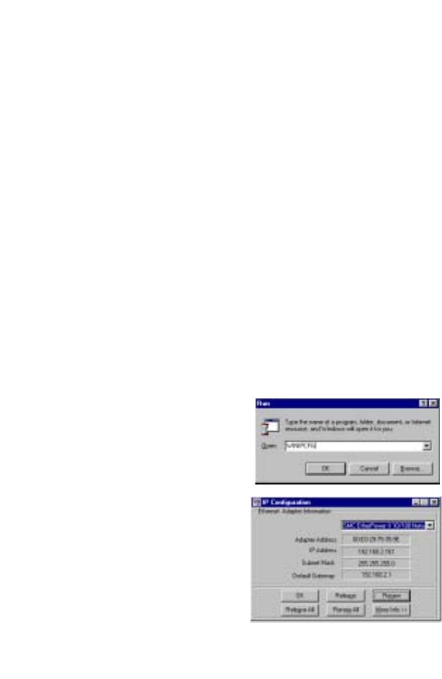
1. Click Start/Run.
2. Type WINIPCFG and click
OK.
3. From the drop-down menu,
select your network card.
Click Release and then
Renew. Verify that your IP
address is now
192.168.2.xxx, your Subnet
Mask is 255.255.255.0 and
your Default Gateway is
192.168. 2.1. These values
confirm that the Router is functioning. Click OK to close the IP
Configuration window.
Configuring Client TCP/IP
18
Configuring Your Computer in Windows NT 4.0
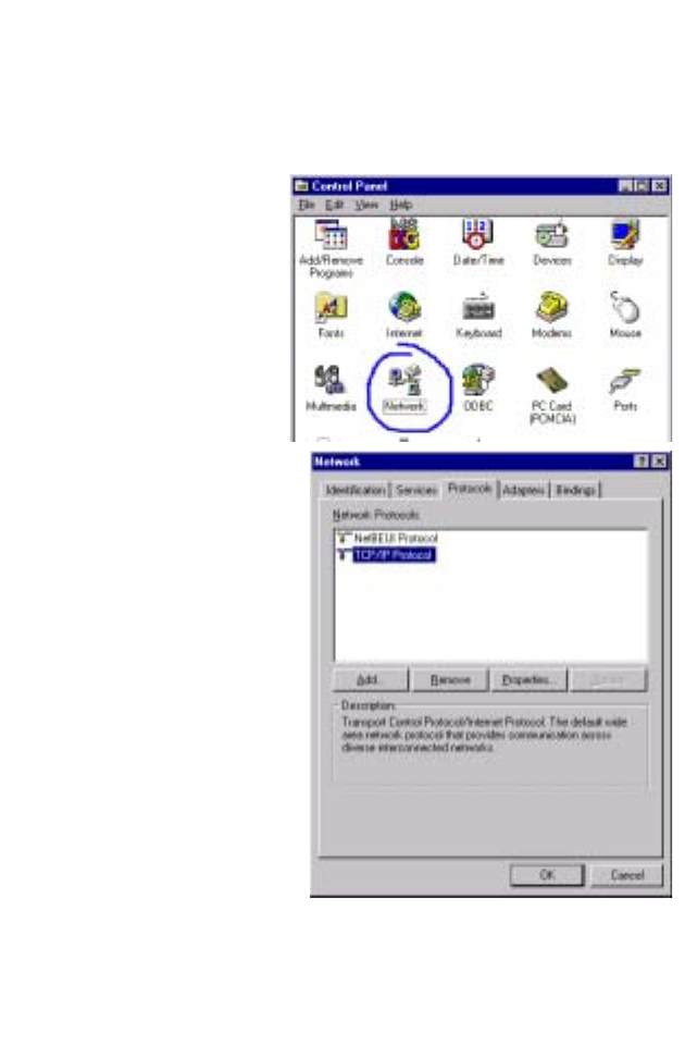
1. From the Windows desktop click Start/Settings/Control Panel.
2. Double-click the
Network icon.
3. Click on the
Protocols tab.
4. Double-click
TCP/IP Protocol.
5. Click on the IP
Address tab.
6. In the Adapter drop-down list, be sure your Ethernet adapter
is selected.
Setting Up TCP/IP
19
7. Click on “Obtain an IP address from a DHCP server.”
8. Click OK to close the window.
9. Windows may copy files and will then prompt you to restart
your system. Click Yes and your computer will shut down and
restart.
Obtain IP Settings From Your Wireless Barricade Router
Now that you have configured your computer to connect to the
Router, it needs to obtain new network settings. By releasing old
IP settings and renewing them with settings from the Router, you
will also verify that you have configured your computer correctly.
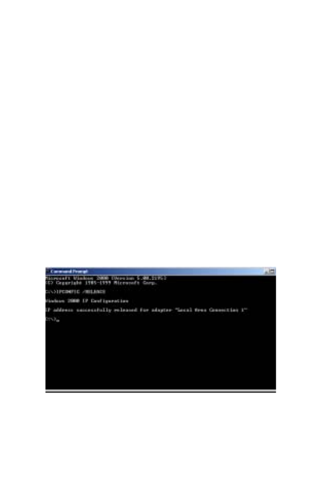
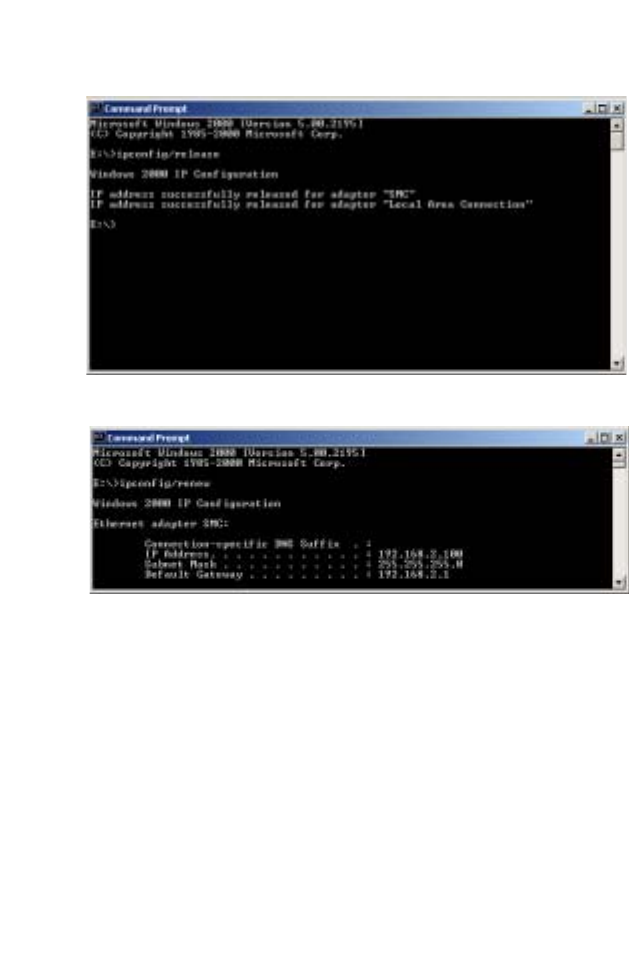
1. On the Windows desktop, click Start/Programs/Command
Prompt.
2. In the Command Prompt window, type IPCONFIG /RELEASE
and press the <ENTER> key.
Configuring Client TCP/IP
20
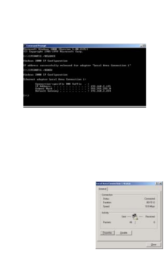
3. Type IPCONFIG /RENEW and press the <ENTER> key. Verify
that your IP Address is now 192.168.2.xxx, your Subnet Mask
is 255.255.255.0 and your Default Gateway is 192.168.2.254.
These values confirm that the Router is functioning
4. Type EXIT and press <ENTER> to close the Command
Prompt window.
Configuring Your Computer in Windows 2000
1. Access your Network settings by clicking Start, then choose
Settings and then select Control Panel.
2. In the Control Panel, locate and double-click the Network and
Dial-up Connections icon.
3. Locate and double-click the
Local Area Connection icon
for the Ethernet adapter that
is connected to the Router.
When the Status dialog box
window opens, click the
Properties button.

Setting Up TCP/IP
21
4. In the Local Area Connection Properties box, verify the box
next to Internet Protocol (TCP/IP) is checked. Then highlight
the Internet Protocol (TCP/IP), and click the Properties
button.
5. Select “Obtain an IP address automatically” to configure your
computer for DHCP. Click the OK button to save this change
and close the Properties window.
6. Click the OK button again to save these new changes.
7. Reboot your PC.
8. To obtain new network settings see “Obtain IP Settings from
Your Wireless Barricade Router” on page 17.
Configuring Your Computer in Windows XP
The following instructions assume you are running Windows XP
with the default interface. If you are using the Classic interface
(where the icons and menus look like previous Windows
versions), please follow the instructions for Windows 2000
outlined above.
1. Access your Network settings by clicking Start, choose
Control Panel, select Network and Internet Connections and
then click on the Network Connections icon.
Configuring Client TCP/IP
22
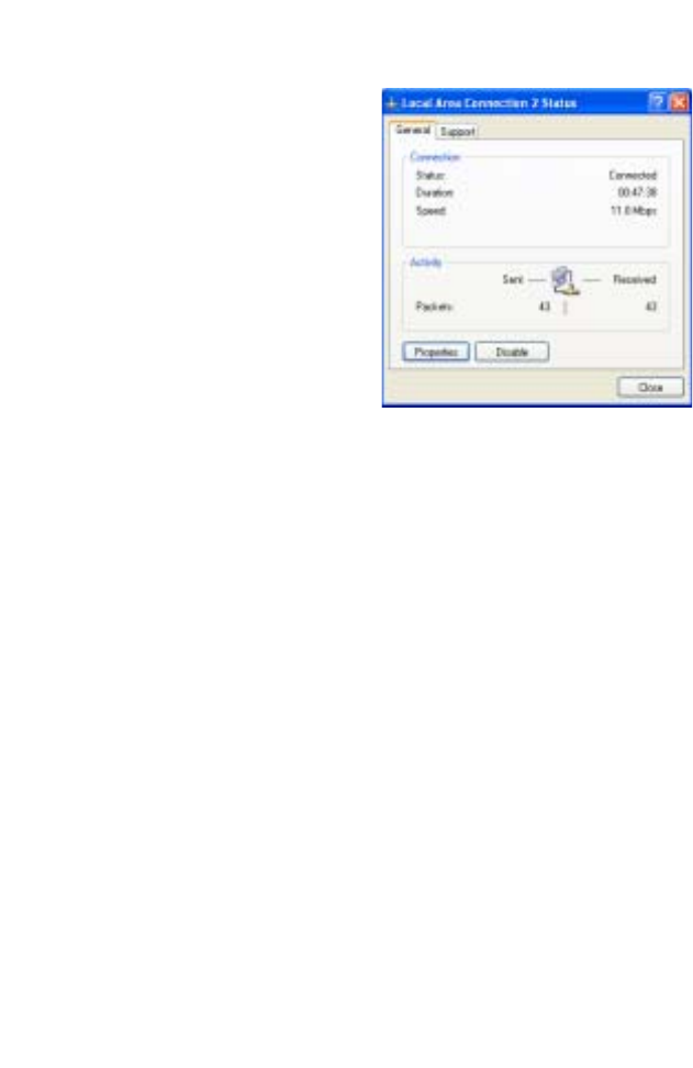
2. Locate and double-click the
Local Area Connection icon
for the Ethernet adapter that
is connected to the Router.
Next, click the Properties
button.
3. In the Local Area Connection Properties box, verify the box
next to Internet Protocol (TCP/IP) is checked. Then highlight
the Internet Protocol (TCP/IP), and click the Properties
button.
4. Select “Obtain an IP address automatically” to configure your
computer for DHCP. Click the OK button to save this change
and close the Properties window.
5. Click the OK button again to save these new changes.
6. Reboot your PC.
Configuring a Macintosh Computer
You may find that the instructions here do not exactly match your
screen. This is because these steps and screen shots were
created using Mac OS 10.2. Mac OS 7.x and above are all very
similar, but may not be identical to Mac OS 10.2.
1. Pull down the Apple Menu. Click System Preferences and
select Network.
Setting Up TCP/IP
23
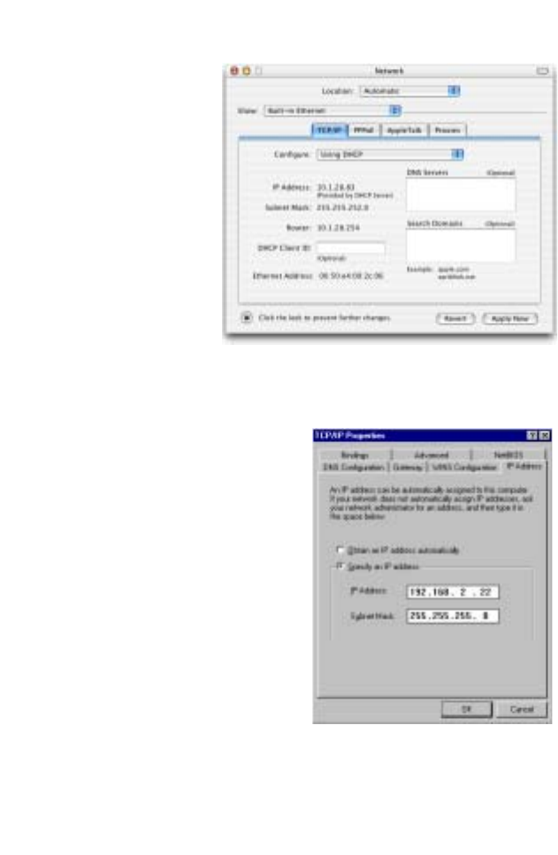
2. Make sure that
Built-in Ethernet
is selected in the
Show field.
3. On the TCP/IP
tab, select Using
DHCP in the
Configure field.
4. Close the
TCP/IP dialog
box.
Manual IP Configuration (for all Windows OS)
1. Check Specify an IP
address on the IP Address
tab. Enter an IP address
based on the default
network 192.168.2.x (where
x is
between 2 and 254), and
use 255.255.255.0 for the
subnet mask.
Configuring Client TCP/IP
24
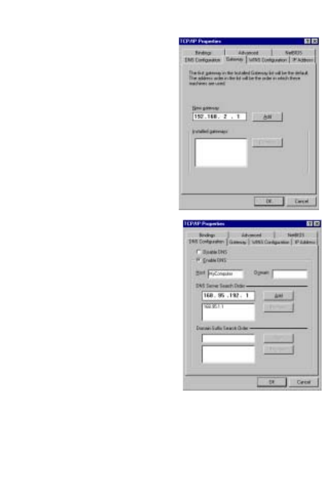
2. In the Gateway tab, add the
IP address of the Router
(default: 192.168.2.1)
in the
New gateway field and click
Add.
3. On the DNS Configuration
tab, add the IP address for
the Router and click Add.
This automatically relays
DNS requests to the DNS
server(s) provided by your
ISP. Otherwise, add specific
DNS servers into the DNS
Server Search Order field
and click Add
.
4. After finishing TCP/IP setup,
click OK, and then reboot
the computer. After that, set
up other PCs on the LAN
according to the procedures described above.

Setting Up TCP/IP
25
Verifying Your TCP/IP Connection
After installing the TCP/IP communication protocols and
configuring an IP address in the same network as the Router,
use the ping command to check if your computer has
successfully connected to the Router. The following example
shows how the ping procedure can be executed in an MS-DOS
window. First, execute the ping command:
ping 192.168.2.1
If a message similar to the following appears:
Pinging 192.168.2.1 with 32 bytes of data:
Reply from 192.168.2.1: bytes=32 time=2ms TTL=64
a communication link between your computer and the Router has
been successfully established.
If you get the following message,
Pinging 192.168.2.1 with 32 bytes of data:
Request timed out.
there may be something wrong in your installation procedure.
Check the following items in sequence:
1. Is the Ethernet cable correctly connected between the Router
and the computer?
The LAN LED on the Router and the Link LED of the network
card on your computer must be on.
2. Is TCP/IP properly configured on your computer?
If the IP address of the Router is 192.168.2.1, the IP address
of your PC must be from 192.168.2.2 - 254 and the default
gateway must be 192.168.2.1.
If you can successfully ping the Router you are now ready to
connect to the Internet!

26
C
ONFIGURING THE
W
IRELESS
B
ARRICADE
R
OUTER
The Wireless Barricade Router can be configured by any
Java-supported browser, i.e., Internet Explorer 4.0 or above.
Using the web management interface, you can configure the
Router and view statistics to monitor network activity.
Note: Before you attempt to configure your router, if you have
access to the Internet please visit www.smc.com and
download the latest firmware update to ensure your
Router is running the latest firmware.
Before you attempt to log into the web-based Administration,
please verify the following.
1. Your browser is configured properly (see below).
2. Disable any firewall or security software that may be running.
3. Confirm that you have a good link LED where your computer
is plugged into the Router. If you don’t have a link light, then
try another cable until you get a good link.
Browser Configuration
Confirm your browser is configured for a direct connection to the
Internet using the Ethernet cable that is installed in the computer.
This is configured through the options/preference section of your
browser.

Navigating the Web Browser Interface
27
Disable Proxy Connection
You will also need to verify that the HTTP Proxy feature of your
web browser is disabled. This is so that your web browser will be
able to view the Router configuration pages. The following steps
are for Internet Explorer and for Netscape. Determine which
browser you use and follow the appropriate steps.
Internet Explorer 5 or above (For Windows)
1. Open Internet Explorer. Click Tools, and then select Internet
Options.
2. In the Internet Options window, click the Connections tab.
3. Click the LAN Settings button.
4. Clear all the check boxes and click OK to save these LAN
settings changes.
5. Click OK again to close the Internet Options window.
Internet Explorer (For Macintosh)
1. Open Internet Explorer. Click Explorer/Preferences.
2. In the Internet Explorer Preferences window, under Network,
select Proxies.
3. Uncheck all check boxes and click OK.
Navigating the Web Browser Interface
To access the Router’s management
interface, enter the Router IP address
in your web browser http://
192.168.2.1. Then click LOGIN.

Configuring the Wireless Barricade Router
28
(By default, the password is smcadmin. The default is case
sensitive.)
Making Configuration Changes
Configurable parameters have a dialog box or a drop-down list.
Once a configuration change has been made on a page, be sure
to click the APPLY or NEXT button at the bottom of the page to
enable the new setting.
Note: To ensure proper screen refresh after a command
entry, ensure that Internet Explorer 5.0 is configured as
follows: Under the menu Tools/Internet Options/
General/Temporary Internet Files/Settings, the setting
for “Check for newer versions of stored pages” should
be “Every visit to the page.”
SETUP WIZARD
29
SETUP WIZARD
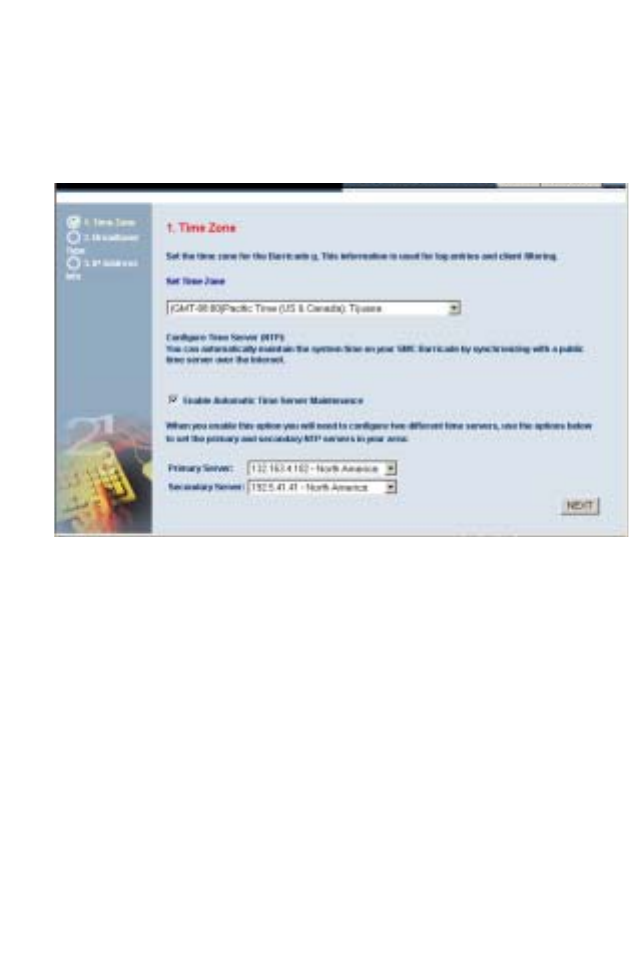
Time Zone
Click on SETUP WIZARD. The first item is Time Zone.
For accurate timing of client filtering and log events, you need to
set the time zone. Select your time zone from the drop-down list.
Check Enable Automatic Time Server Maintenance to
automatically maintain the Router’s system time by synchronizing
with a public time server over the Internet. Then configure two
different time servers by selecting the options in the Primary
Server and Secondary Server fields, and click NEXT.
Configuring the Wireless Barricade Router
30
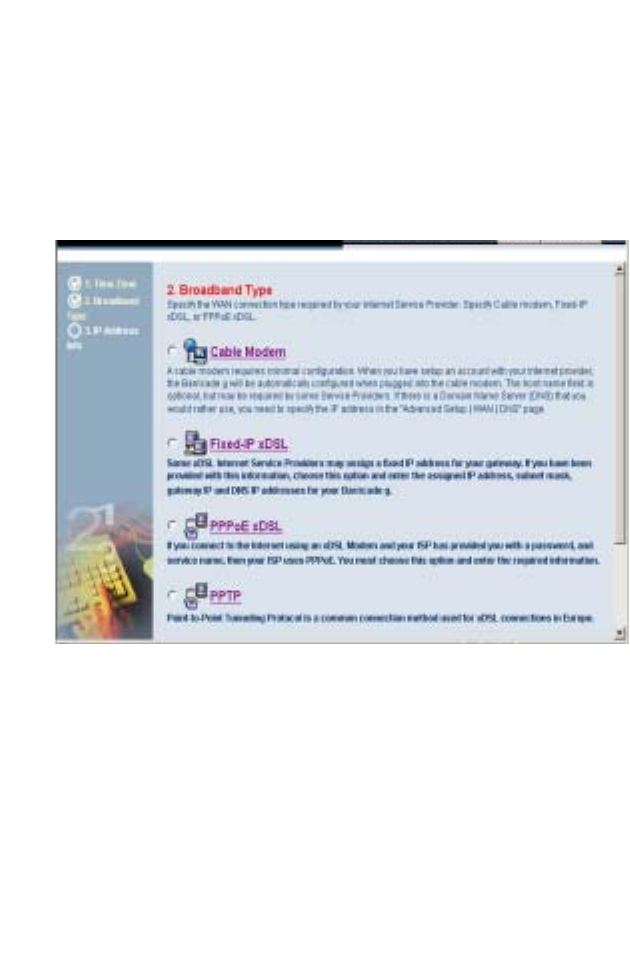
Broadband Type
Select the type of broadband connection you have.
For a cable modem connection see the following page. For a
Fixed-IP xDSL connection see “Fixed-IP xDSL” on page 31, for a
PPPoE xDSL connection, see “PPPoE” on page 31, and for
BigPond connection, see “BigPond” on page 33.
SETUP WIZARD
31
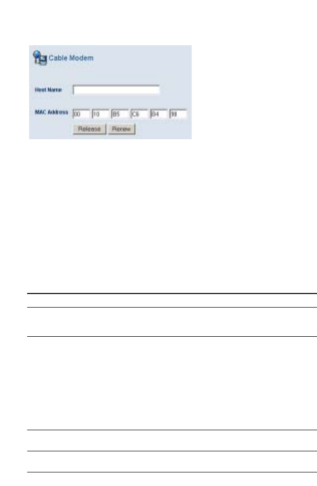
Cable Modem
After selecting Cable Modem as the Broadband Type, a
message will appear stating that your data has been successfully
saved.
Note: Select Home to return to the home page, then select
Advanced Settings/WAN to configure the required
parameters. (See “WAN” on page 38.)
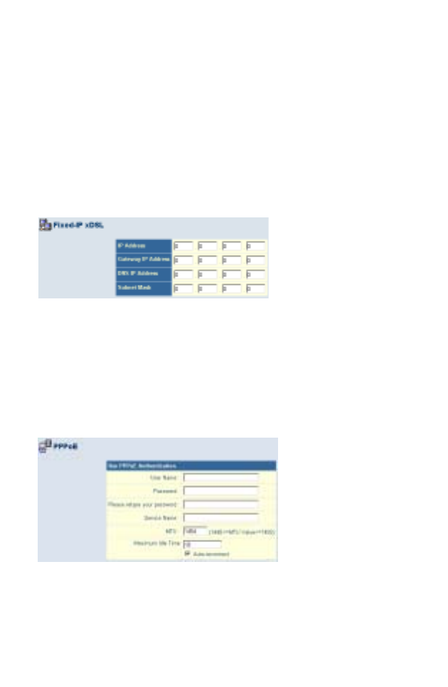
Fixed-IP xDSL
Some xDSL Internet Service Providers may assign a fixed
(static) IP address. If you have been provided with this
information, choose this option and enter the assigned IP
address, gateway IP address, DNS IP addresses, and subnet
mask. Click FINISH to complete the setup.
PPPoE
Enter the PPPoE User Name and Password assigned by your
Service Provider. The Service Name is normally optional, but
may be required by some service providers.
Leave the Maximum Transmission Unit (MTU) at the default
value (1454) unless you have a particular reason to change it.
Configuring the Wireless Barricade Router
32
Enter a Maximum Idle Time (in minutes) to define a maximum
period of time for which the Internet connection is maintained
during inactivity. If the connection is inactive for longer than the
Maximum Idle Time, it will be dropped. (Default: 10)
Enable the Auto-reconnect option to automatically re-establish
the connection as soon as you attempt to access the Internet
again. Click FINISH to complete the setup.
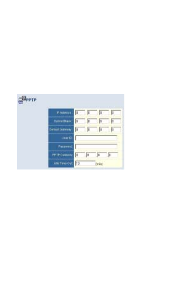
Point-to-Point Tunneling Protocol (PPTP)
Point-to-Point Tunneling Protocol is a common connection
method used for xDSL connections in Europe. It can be used to
join different physical networks using the Internet as an
intermediary.
If you have been provided with the information as shown on the
screen, enter the assigned IP address, subnet mask, default
gateway IP address, user ID and password, and PPTP Gateway.
Enter a maximum Idle Time Out (in minutes) to define a
maximum period of time for which the Internet connection is
maintained during inactivity. If the connection is inactive for
longer than the Idle Time Out, it will be dropped. (Default: 10)
Click FINISH to complete the setup. (Refer to “Point-to-Point
Tunneling Protocol (PPTP)” on page 41 for details.)
Advanced Setup
33
BigPond
If you use the BigPond Internet Service which is available in
Australia, enter the host name and AMC address for BigPond
authentication. Click FINISH to complete the setup.
Advanced Setup
Use the web management interface to define system
parameters, manage and control the Router and its ports, or
monitor network conditions. The following table outlines the
selections available from this program.
Menu Description
System Sets the local time zone, the password for administrator access,
and the IP address of a PC that will be allowed to manage the
Router remotely.
WAN Specifies the Internet connection type:
• Dynamic IP host configuration and the physical MAC address
of each media interface
• PPPoE configuration
• PPTP configuration
• Static IP and ISP gateway address
• BigPond (Internet service available in Australia)
• Specifies DNS servers to use for domain name resolution.
LAN Sets the TCP/IP configuration of the Router’s LAN interface and
all DHCP clients.
Wireless Configures the radio frequency, SSID, encryption, and 802.1x
for wireless communications.

Configuring the Wireless Barricade Router
34
NAT Shares a single ISP account with multiple users, sets up virtual
servers.
Firewall Configures a variety of security and specialized functions,
including: Access Control, Hacker Prevention, and DMZ.
DDNS Dynamic DNS provides users on the Internet with a method to
tie their domain name to a computer or server.
UPnP With Universal Plug and Play, a device can automatically and
dynamically join a network, obtain an IP address, communicate
its capabilities, and learn about the presence and capabilities of
other devices. Devices can then directly communicate with each
other. This further enables peer-to-peer networking.
Tools Contains options to back up & restore the current configuration,
restore all configuration settings to the factory defaults, update
system firmware, or reset the system.
Status Provides WAN connection type and status, firmware and
hardware version numbers, system IP settings, as well as
DHCP, NAT, and Firewall information.
Displays the number of attached clients, the firmware versions,
the physical MAC address for each media interface, and the
hardware version and serial number.
Shows the security and DHCP client log.
Menu Description

Advanced Setup
35
SYSTEM
Time Zone
Set the time zone and time server for the Router. This
information is used for log entries and client access control.
Check Enable Automatic Time Server Maintenance to
automatically maintain the Router’s system time by synchronizing
with a public time server over the Internet. Then configure two
different time servers by selecting the options in the Primary
Server and Secondary Server fields.

Configuring the Wireless Barricade Router
36
Password Settings
Use this menu to restrict access based on a password. By
default, there is no password. For security you should assign one
before exposing the Router to the Internet.
Passwords can contain from 3–12 alphanumeric characters and
are not case sensitive.
Note: If your password is lost, or you cannot gain access to
the user interface, press the Reset button on the rear
panel (holding it down for at least five seconds) to
restore the factory defaults. (The default password is
smcadmin.)
Enter a maximum Idle Time Out (in minutes) to define a
maximum period of time for which the login session is maintained
during inactivity. If the connection is inactive for longer than the
maximum idle time, it will perform system logout, and you have to
log into the web management system again.
(Default: 10 minutes)

Advanced Setup
37
Remote Management
Remote Management allows a remote PC to configure, manage,
and monitor the Router using a standard web browser. Check
Enable and enter the IP address of the remote host. Click
APPLY.
Note: If you specify 0.0.0.0 as this IP address, any host can
manage the Router.
Syslog Server
The Syslog Server tool will automatically download the Barricade
log to the server IP address specified by the user. Enter the
Server LAN IP Address and check the Enabled box to enable this
function.

Configuring the Wireless Barricade Router
38
WAN
Specify the WAN connection type provided by your Internet
Service Provider, then click More Configuration to enter detailed
configuration parameters for the selected connection type.

Advanced Setup
39
Dynamic IP
The Host Name is optional, but may be required by some ISPs.
The default MAC address is set to the WAN’s physical interface
on the Router. Use this address when registering for Internet
service, and do not change it unless required by your ISP. If your
ISP used the MAC address of an Ethernet card as an identifier
when first setting up your broadband account, only connect the
PC with the registered MAC address to the Router and click the
Clone MAC Address button. This will replace the current Router
MAC address with the already registered Ethernet card MAC
address.
If you are unsure of which PC was originally set up by the
broadband technician, call your ISP and request that they
register a new MAC address for your account. Register the
default MAC address of the Router.

Configuring the Wireless Barricade Router
40
Point-to-Point Over Ethernet (PPPoE)
Enter the PPPoE User Name and Password assigned by your
Service Provider. The Service Name is normally optional, but
may be required by some service providers.
The MTU (Maximum Transmission Unit) governs the maximum
size of the data packets. Leave this on the default value (1454)
unless you have a particular reason to change it.
Enter a Maximum Idle Time (in minutes) to define a maximum
period of time for which the Internet connection is maintained
during inactivity. If the connection is inactive for longer than the
Maximum Idle Time, it will be dropped. (Default: 10 minutes)
Enable the Auto-reconnect option to automatically re-establish
the connection as soon as you attempt to access the Internet
again.

Advanced Setup
41
Point-to-Point Tunneling Protocol (PPTP)
Point-to-Point Tunneling Protocol (PPTP) can be used to join
different physical networks using the Internet as an intermediary.
Using the above screen allows client PCs to establish a normal
PPTP session and provides hassle-free configuration of the
PPTP client on each client PC.
Enter the assigned IP address, subnet mask and default gateway
IP address (usually supplied by your ISP), and then the PPTP
User ID, Password and PPPTP Gateway IP address.
Enter a maximum Idle Time Out (in minutes) to define a
maximum period of time for which the PPTP connection is
maintained during inactivity. If the connection is inactive for
longer than the Maximum Idle Time, it will be dropped.
(Default: 10 minutes)

Configuring the Wireless Barricade Router
42
Static IP Address
If your Internet Service Provider has assigned a fixed IP address,
enter the assigned address and subnet mask for the Router, then
enter the gateway address of your ISP.
You may need a fixed address if you want to provide Internet
services, such as a web server or FTP server.
BigPond

Advanced Setup
43
BigPond is a service provider in Australia that uses a heartbeat
system to maintain the Internet connection. On this page you can
configure the user settings including, User Name, Password, and
the Authentication Service Name.
DNS
Domain Name Servers map numerical IP addresses to the
equivalent domain name (e.g., www.smc.com). Your ISP should
provide the IP address of one or more domain name servers.
Enter those addresses in this screen.

Configuring the Wireless Barricade Router
44
LAN
•LAN IP – Use the LAN menu to configure the LAN IP address
for the Router and to enable the DHCP server for dynamic
client address allocation.
•Set a period for the lease time if required. For home networks
this may be set to Forever, which means there is no time limit
on the IP address lease.
•IP Address Pool – A dynamic IP address range may be
specified (192.168.2.2–254). IP addresses running from
192.168.2.100–199 are the default value. Once the IP
addresses, e.g. 192.168.2.100–199, have been assigned,
these IP addresses will be part of the dynamic IP address
pool. IP addresses from 192.168.2.2–99, and
192.168.2.200–254 will be available as static IP addresses.
Remember not to include the address of the Router in the
client address pool. Also remember to configure your client
PCs for dynamic IP address allocation.

Advanced Setup
45
WIRELESS
To configure the Router as a wireless access point for wireless
clients (either stationary or roaming), all you need to do is define
the radio channel, the Service Set identifier (SSID), and security
options.
Channel and SSID
You must specify a common radio channel and SSID (Service
Set ID) to be used by the Router and all of your wireless clients.
Be sure you configure all of your clients to the same values.
Configuring the Wireless Barricade Router
46
SSID: The Service Set ID. This should be set to the same value
as the other wireless devices in your network.
SSID Broadcast: Broadcasting the SSID on the wireless network
for easy connection with client PCs. For security reasons, you
should disable SSID broadcast. (Default: Enable)
Note: The SSID is case sensitive and can consist of up to 32
alphanumeric characters.
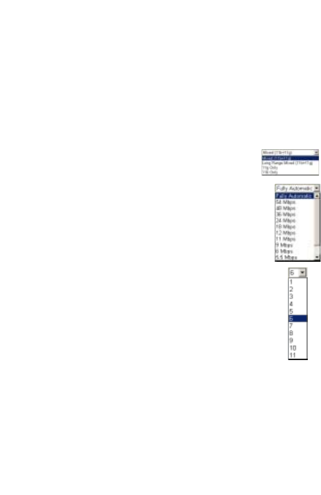
Wireless Mode: Set the communication mode for
the Router. Default: Mixed (11b+11g)
Transmission Rate: Set the rate of data
transmitted from the Router. The lower the data rate,
the longer the transmission distance. (Default: Fully
Automatic.)
Channel: The radio channel through which the Router
communicates with PCs in its BSS. (Default: 6)
Note: The available channel settings are limited by
local regulations.
g Nitro: In a crowded 2.4 MHz frequency, the
connection speed is much lower than the promised 54 Mbps. The
g Nitro implemented by Intersil’s Prism Nitro technology
dramatically enhances your wireless network speeds. It provides
up to 50% more throughput in 11g only environment, and
improves network throughput by 3 times in mixed mode.

Advanced Setup
47
Security
If you are transmitting sensitive data across radio channels, you
should enable wireless security.

Configuring the Wireless Barricade Router
48
WEP
Wired Equivalent Privacy (WEP) encryption requires you to use
the same set of encryption/decryption keys for the Router and all
of your wireless clients.
WEP mode: You can choose disabled, 64-bit or 128-bit
encryption.
Key Provisioning: Select a key type of static key or dynamic key.
Static WEP Key Setting
You may manually enter the keys or automatically generate
encryption keys. To manually configure the keys, enter 10 digits
for each 64-bit key, or enter 26 digits for the single 128-bit key. (A
hexadecimal digit is a number or letter in the range 0-9 or A-F.)
For automatic 64-bit security, check the box of Passphrase, enter
a passphrase and click APPLY. Four keys will be generated.
Choose a key ID (1-4) from the drop-down list or accept the
default key.

Advanced Setup
49
If you use encryption, configure the same keys used for the
Router on each of your wireless clients. Note that Wired
Equivalent Privacy (WEP) protects data transmitted between
wireless nodes, but does not protect any transmissions over your
wired network or over the Internet.
WPA
Wi-Fi Protected Access (WPA) combines Temporal Key Integrity
Protocol (TKIP) and 802.1x mechanisms. It provides dynamic
key encryption and 802.1x authentication service. With TKIP,
WPA uses 48-bit initialization vectors, calculates an 8-byte
message integrity code, and generates an encryption key
periodically. For authentication, it allows you to use 802.1x
authentication for an environment with a RADIUS server installed
on your network. Selecting the Pre-shared Key enables WPA to
use the pre-shared key in a SOHO network.

Configuring the Wireless Barricade Router
50
802.1X
Management access will be checked against the authentication
database stored on the Router. If an authentication RADIUS
Field Default Parameter Description
Cypher suite TKIP One of the security mechanism used
by WPA for frame body and CRC
frame encryption
Authentication 802.1X Select the authentication mode.
• 802.1X: It is for an enterprise
network with a RADIUS server
installed.
• Pre-shared Key: It is for a SOHO
network without any authentication
server installed.
Pre-shared key
type
Passphrase
(8~63 characters)
Select the key type as in pass-phrase
or in 64-Hex characters
Pre-shared Key none Specify in pass-phrase style or in
64-Hex characters.
Group Key
Re_Keying
Disable The period of renewing broadcast/
multicast key

Advanced Setup
51
server is used, you must specify the secret key of the
Message-Authenticator attribute, i.e., Message Digest-5 (MD5),
and the corresponding parameters in the RADIUS Server
Parameters field for the remote authentication protocol.
•General Parameters
•RADIUS Server Parameters
Field Default Parameter Description
Enable 802.1X Yes Starts using 802.1x security control.
Session Idle
Timeout
300 seconds Defines a maximum period of time for
which the connection is maintained
during inactivity.
Re-Authentication
Period
3600 seconds
Defines a maximum period of time for
which the RADIUS server will
dynamically re-assign a session key
to a connected client station.
Quiet Period 60 seconds Defines a maximum period of time for
which the Router will wait between
failed authentications.
Server Type RADIUS Selects the authentication server
type.
Field Defaults Description
Server IP 192.168.1.1 The IP address of the RADIUS server.
Server Port 1812 UDP port is used for RADIUS authentication
messages.
Secret Key none
Defines a text string on both the RADIUS
client and server to secure RADIUS traffic.
The RADIUS server requires MD5
Message-Authenticator attribute for all
access request messages. The 802.1x
authentication scheme is supported by using
the Extensible Authentication Protocol
(EAP) over the RADIUS server.
NAS-ID none Defines the request identifier of the Network
Access Server (NAS)

Configuring the Wireless Barricade Router
52
NAT
From this section you can configure the Virtual Server, and
Special Application features that provide control over the TCP/
UDP port openings in the router’s firewall. This section can be
used to support several Internet based applications such as web,
E-mail, FTP, and Telnet.
NAT allows one or more public IP addresses to be shared by
multiple internal users. Enter the Public IP address you wish to
share into the Global IP field. Enter a range of internal IPs that
will share the global IP.

Advanced Setup
53
Virtual Server
If you configure the Router as a virtual server, remote users
accessing services such as web or FTP at your local site via
public IP addresses can be automatically redirected to local
servers configured with private IP addresses. In other words,
depending on the requested service (TCP/UDP port number), the
Router redirects the external service request to the appropriate
server (located at another internal IP address).
For example, if you set Type/Public Port to TCP/80 (HTTP or
web) and the Private IP/Port to 192.168.2.2/80, then all HTTP
requests from outside users will be transferred to 192.168.2.2 on
port 80. Therefore, by just entering the IP Address provided by
the ISP, Internet users can access the service they need at the
local address to which you redirect them.
The more common TCP service ports include:
HTTP: 80, FTP: 21, Telnet: 23, and POP3: 110

Configuring the Wireless Barricade Router
54
Special Applications
Some applications, such as Internet gaming, videoconferencing,
Internet telephony and others, require multiple connections.
These applications cannot work with Network Address
Translation (NAT) enabled. If you need to run applications that
require multiple connections, use the following screen to specify
the additional public ports to be opened for each application.
Specify the public port number normally associated with an
application in the Trigger Port field. Set the protocol type to TCP
or UDP, then enter the ports that the application requires.
Popular applications requiring
multiple ports are listed in the Popular
Applications field. From the
drop-down list, choose the application
and then choose a row number to copy this data into.
Note: Choosing a row that already contains data will
overwrite the current settings.

Advanced Setup
55
Example:
For a full list of ports and the services that run on them, see
www.iana.org/assignments/port-numbers.
ID Trigger
Port
Trigger
Type
Public Port Public Type Comment
1 6112 UDP 6112 UDP Battle.net
2 28800 TCP 2300-2400,
47624
TCP MSN Game
Zone

Configuring the Wireless Barricade Router
56
FIREWALL
The Router firewall can provide access control of connected
client PCs, block common hacker attacks, including IP Spoofing,
Land Attack, Ping of Death, IP with zero length, Smurf Attack,
UDP port loopback, Snork Attack, TCP null scan, and TCP SYN
flooding. The firewall does not significantly affect system
performance, so we advise leaving it enabled to protect your
network users.
Access Control
Using this option allows you to specify different privileges based
on IP address for the client PCs.
Note: Click on Add PC and define the appropriate settings for
client PC services (as shown in the following screen).

Advanced Setup
57
Access Control Add PC
This page allows users to define service limitations of client PCs,
including IP address, service type and scheduling rule criteria.

Configuring the Wireless Barricade Router
58
MAC Filter
This section provides MAC filtering configuration information.
To use MAC address filtering, you must enter a list of allowed/
denied client MAC addresses into the filtering table. You can
define up to 32 clients using the MAC address filtering table.
When enabled only the MAC addresses entered will have access
to your network. All other devices will be denied access to your
network.

Advanced Setup
59
URL Blocking
To configure the URL Blocking feature, use the table below to
specify the web sites (www.somesite.com) and/or keywords you
want to filter on your network.
To complete this configuration, you will need to create or modify
an access rule in “Access Control” on page 56. To modify an
existing rule, click the Edit option next to the rule you want to
modify. To create a new rule, click on the Add PC option.
From the Access Control Add PC section check the option for
“WWW with URL Blocking” in the Client PC Service table to filter
out the web sites and keywords specified below.
Use the above screen to block access to web sites or to web
URLs containing the keyword specified in the table.

Configuring the Wireless Barricade Router
60
Schedule Rule
The Schedule Rule feature allows you to configure specific rules
based on time and date. These rules can then be used to
configure more specific Access Control.

Advanced Setup
61
Add Schedule Rule
Enables Schedule-based Internet access control.
1. Click Add Schedule Rule.
2. Define the settings for the schedule rule (as shown on the
following screen).
3. Click OK and then click the APPLY button to save your
settings.

Configuring the Wireless Barricade Router
62
Hacker Prevention
The Hacker Prevention feature limits access for incoming traffic
at the WAN port.

Advanced Setup
63
• SPI and Anti-DoS firewall protection (Default: Enabled) –
When the SPI (Stateful Packet Inspection) feature is turned
on, all incoming packets will be blocked except for those types
marked with a check in the Stateful Packet Inspection section.
• RIP Defect (Default: Enabled) – If an RIP request packet is
not acknowledged to by the Router, it will stay in the input
queue and not be released. Accumulated packets could
cause the input queue to fill, causing severe problems for all
protocols. Enabling this feature prevents the packets
accumulating.
• Discard Ping from WAN (Default: Disabled) – Prevents the
router from responding to any PING request on the WAN port.
• Stateful Packet Inspection – This is called a “stateful” packet
inspection because it examines the contents of the packet to
determine the state of the communications; i.e., it ensures that
the stated destination computer has previously requested the
current communication. This is a way of ensuring that all

Configuring the Wireless Barricade Router
64
communications are initiated by the recipient computer and
are taking place only with sources that are known and trusted
from previous interactions. In addition to being more rigorous
in their inspection of packets, stateful inspection firewalls also
close off ports until connection to the specific port is
requested.
When particular types of traffic are checked, only the
particular type of traffic initiated from the internal LAN will be
allowed. For example, if the user only checks FTP Service in
the Stateful Packet Inspection section, all incoming traffic will
be blocked except for FTP connections initiated from the local
LAN.
Stateful Packet Inspection allows you to select different
application types that are using dynamic port numbers. If you
wish to use the Stateful Packet Inspection (SPI) to block
packets, click on the Yes radio button in the “Enable SPI and
Anti-DoS firewall protection” field and then check the
inspection type that you need, such as Packet Fragmentation,
TCP Connection, UDP Session, FTP Service, H.323 Service,
and TFTP Service.
• When hackers attempt to enter your network, we can alert
you by email – Enter your email address. Specify your SMTP
and POP3 servers, user name, and password.
• Connection Policy – Enter the appropriate values for TCP/
UDP sessions as described in the following table.
Parameter Defaults Description
Fragmentation
half-open wait
10 sec Configures the number of seconds that a
packet state structure remains active. When
the timeout value expires, the router drops the
unassembled packet, freeing that structure for
use by another packet.
TCP SYN wait 30 sec Defines how long the software will wait for a
TCP session to synchronize before dropping
the session.
TCP FIN wait 5 sec Specifies how long a TCP session will be
maintained after the firewall detects a FIN
packet.

Advanced Setup
65
TCP connection
idle timeout
3600 sec
(1 hour)
The length of time a TCP session will be
maintained if there is no activity.
UDP session idle
timeout
30 sec The length of time a UDP session will
maintained if there is no activity.
H.323 data channel
idle timeout
180 sec The length of time an H.323 session will be
maintained if there is no activity.
Parameter Defaults Description

Configuring the Wireless Barricade Router
66
DoS Detect Criteria
Set up DoS (Denial-of-Service) and port scan criteria in the
spaces provided (as shown below).
Parameter Defaults Description
Total incomplete TCP/UDP
sessions HIGH
300 sessions Defines the rate of newly
unestablished sessions that will
cause the software to start
deleting half-open sessions.
Total incomplete TCP/UDP
sessions LOW
250 sessions Defines the rate of newly
unestablished sessions that will
cause the software to stop
deleting half-open sessions.
Incomplete TCP/UDP sessions
(per min.) HIGH
250 sessions Maximum number of allowed
incomplete TCP/UDP sessions
per minute.
Incomplete TCP/UDP sessions
(per min.) LOW
200 sessions Minimum number of allowed
incomplete TCP/UDP sessions
per minute. Set this to “0” if no
minimum setting is required.
Maximum incomplete TCP/UDP
sessions number from same
host
10 sessions Maximum number of incomplete
TCP/UDP sessions from the
same host.
Incomplete TCP/UDP sessions
detect sensitive time period
300 msec Length of time before an
incomplete TCP/UDP session is
detected as incomplete.
Maximum half-open
fragmentation packet number
from same host
30 Maximum number of half-open
fragmentation packets from the
same host.
Half-open fragmentation detect
sensitive time period
1 sec Length of time before a half-open
fragmentation session is
detected as half-open.
Flooding cracker block time 300 sec Length of time from detecting a
flood attack to blocking of the
attack.

Advanced Setup
67
DMZ
If you have a client PC that cannot run an Internet application
properly from behind the firewall, then you can open the client up
to unrestricted two-way Internet access. Enter the IP address of
a DMZ host to this screen. Adding a client to the DMZ
(Demilitarized Zone) may expose your local network to a variety
of security risks, so only use this option as a last resort.

Configuring the Wireless Barricade Router
68
DDNS
Provider – This DNS feature is powered by either DynDNS, or
TZO.com. With a DDNS connection you can host your own web
site, E-mail server, FTP site, and more at your own location even
if you have a dynamic IP address. (Default: Disable)
Domain Name – A series of alphanumeric strings separated by
periods that maps to the address of a the Router network
connection and identifies the owner of the address.
Dynamic DNS provides users on the Internet with a method to tie
their domain name to the router or server. DDNS allows your
domain name to follow your IP address automatically by having
your DNS records changed when your IP address changes.
The section also has a “Server Configuration” section that
automatically opens the port options checked in the Virtual
Server section. Simply enter in the IP Address of your server,

Advanced Setup
69
such as a web server, and then click on the port option “HTTP
Port 80” so users can access your server from the WAN
connection (Internet).
UPnP
Enable UPnP by checking ON in the screen above. UPnP allows
the device to automatically:
•dynamically join a network
•obtain an IP address
•convey its capabilities and learn about the presence and
capabilities of other devices. (Default: OFF)

Configuring the Wireless Barricade Router
70
TOOLS
Use the Tools menu to back up the current configuration, restore
a previously saved configuration, restore factory settings, update
firmware, and reboot the Router.
Configuration Tools
•Backup Router Configuration – Saves the Router’s
configuration settings to a file.
•Restore from saved Configuration file
(2804WBRP_backup.bin) – Restores the settings from a
saved backup configuration file.
•Restore Barricade to Factory Defaults – Restores the Router
settings back to the factory defaults.

Advanced Setup
71
Firmware Upgrade
Use this screen to update the firmware or user interface to the
latest versions. Download the upgrade file from the SMC web
site (www.smc.com) and save it to your hard drive. In the
Upgrade Target field, choose Firmware. Then click Browse to
look for the previously downloaded file. Click APPLY. Check the
Status page Information section to confirm that the upgrade
process was successful.
Reboot
Click REBOOT ROUTER to reset the Router. Click OK to reboot.
The reset will be complete when the power LED stops blinking.
Note: If you use the Reset button on the front panel, the
Router performs a power reset. If the button is

Configuring the Wireless Barricade Router
72
depressed for over five seconds, all the LEDs will
illuminate and the factory settings will be restored.

Advanced Setup
73
STATUS
The Status screen displays WAN/LAN connection status,
firmware, and hardware version numbers, attempts to access
your network, as well as information on DHCP clients connected
to your network.
The following items are included on this screen:
Section Description
INTERNET Displays WAN connection type and status.
GATEWAY Displays system IP settings, as well as DHCP and Firewall
status.
INFORMATION Displays the number of attached clients, the firmware
versions, the physical MAC address for each media
interface, as well as the hardware version and serial number.
Security Log Displays illegal attempts to access your network.
Save Click on this button to save the security log file.
Clear Click on this button to delete the access log.
Refresh Click on this button to refresh the screen.
DHCP Client Log Displays information on all DHCP clients on your network.
74
TROUBLESHOOTING
The information outlined in this section describes some useful
steps for getting your computer and the Router online.
A. Verify your connection to the Router
If you are unable to access the Router’s web-based
administration pages then you may not be properly connected or
configured. The screen shots in this section were taken on a
Windows 2000 machine, but the same steps will apply to
Windows 95/98/Me/XP.
To determine your TCP/IP configuration status please follow the
steps below:
1. Click Start then choose Run.
2. Type cmd or command to open a DOS prompt.
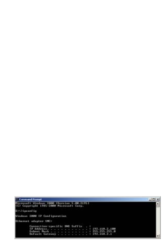
3. In the DOS window, type ipconfig and verify the information
that is displayed.
4. If your computer is set up for DHCP, then your TCP/IP
configuration should be similar to the information displayed:
•IP Address: 192.168.2.x (x is number between 100 and
199 by default.)
•Subnet: 255.255.255.0
•Gateway: 192.168.2.1

Troubleshooting
75
If you have an IP address that starts with 169.254.xxx.xxx then
see the next section.
If you have another IP address configured, then see section C.
B. I am getting an IP Address that starts with
169.254.xxx.xxx
If you are getting this IP Address, then you need to check that
you are properly connected to the Router.
Confirm that you have a good link light on the Router for the port
this computer is connected to. If not, please try another cable.
If you have a good link light, please open up a DOS window as
described in the previous section and type ipconfig/renew.
If you are still unable to get an IP Address from the Router,
reinstall your network adapter. Please refer to your adapter
manual for information on how to do this.
C. I have another IP Address displayed
If you have another IP address listed then the PC may not be
configured for a DHCP connection. Please refer to “Configuring
Client TCP/IP” on page 12 for information.
Once you have confirmed your computer is configured for DHCP,
then please follow the steps below.
1. Open a DOS window as described above.
Troubleshooting
76
2. Type ipconfig/release.
3. Then type ipconfig/renew.
D. The 10/100 LED does not light after a connection is made.
1. Check that the host computer and the Router are both
powered on.
2. Be sure the network cable is connected to both devices.
3. Verify that Category 5 cable is used if you are operating at
100 Mbps, and that the length of any cable does not exceed
100 m (328 ft).
4. Check the network card connections.
5. The 10BASE-T/100BASE-TX port, network card, or cable
may be defective.

77
SPECIFICATIONS
Below is an outline of the technical specifications for the
SMC2304WBR-AG.
Standards
IEEE 802.3 10BASE-T Ethernet
IEEE 802.3u 100BASE-TX Fast Ethernet
IEEE 802.11a
IEEE 802.11b
IEEE 802.11g
WAN Interface
10BASE-T/100BASE-TX
LAN Interfaces
10BASE-T/100BASE-TX
4 RJ-45 ports: LAN data transfer rate is up to 10/20 Mbps
(10BASE-T half/full duplex) or 100/200 Mbps (100BASE-TX
half/full duplex)
Antenna
2 detachable antennas with reversed SMA connectors
Management
Browser-based management
Both DHCP Server and Client provided
Advanced Features
Dynamic IP Address Configuration – DHCP, DNS
Wireless Security – 64/128-bit WEP encryption, 802.1x, SSID
broadcast disabled, MAC address filtering
Firewall – Access Control, hacker prevention, logging
Virtual Server via NAT & NAPT
Virtual Private Network – PPTP, L2TP, IPSec pass-through
Intrusion Detection, E-mail Alerts, Parental Control

Specifications
78
Indicator Panel
Power, WLAN, WAN (Link, Activity), LAN (Link/Activity,
Speed - 10/100 Mbps)
Dimensions
130 x 85 x 32 mm (5.12 x 3.35 x 1.26 in.)
Weight
370 g (13.05 oz)
Input Power
12 V, 1 A
Maximum Current
0.04 ARMS max. @ 110 V/240 V
Power Consumption
5 Watts max. @ 100-240 VAC
Internet Standards
RFC 826 ARP, RFC 791 IP, RFC 792 ICMP, RFC 768 UDP, RFC
793 TCP, RFC 854-859 TELNET, RFC 1321 MD5, RFC 1497
BOOTP Extension, RFC 1570 PPP LCP Extension, RFC 1631
NAT, RFC1661 PPP, RFC 1700 Assigned Numbers, RFC 1866
HTML, RFC 1945 HTTP, RFC 1994 CHAP, RFC 2131 DHCP,
RFC 2637 PPTP
Temperature
Operating 0 to 40 °C (32 to 104 °F)
Storage -40 to 70 °C (-40 to 158 °F)
Humidity
5% to 95% (noncondensing)

Specifications
79
Compliances
CE Mark
Emissions
FCC Class B
Industry Canada Class B
EN55022 (CISPR 22) Class B
Immunity
EN 61000-3-2/3
EN 61000-4-2/3/4/5/6/8/11

Specifications
80

38 Tesla
Irvine, CA 92618
Phone: (949) 679-8000
Model Number: SMC2304WBR-AG
Revision number: E102003-R01 F1.0
FOR TECHNICAL SUPPORT, CALL:
From U.S.A. and Canada (24 hours a day, 7 days a week)
(800) SMC-4-YOU; Phn: (949) 679-8000; Fax: (949) 679-1481
From Europe : Contact details can be found on
www.smc-europe.com or www.smc.com
INTERNET
E-mail addresses:
techsupport@smc.com
european.techsupport@smc-europe.com
Driver updates:
http://www.smc.com/index.cfm?action=tech_support_drivers_downloads
World Wide Web:
http://www.smc.com
http://www.smc-europe.com
FOR LITERATURE OR ADVERTISING RESPONSE, CALL:
U.S.A. and Canada: (800) SMC-4-YOU; Fax (949) 679-1481
Spain: 34-91-352-00-40; Fax 34-93-477-3774
UK: 44 (0) 1932 866553; Fax 44 (0) 118 974 8701
France: 33 (0) 41 38 32 32; Fax 33 (0) 41 38 01 58
Italy: 39 (0) 335 5708602; Fax 39 02 739 14 17
Benelux: 31 33 455 72 88; Fax 31 33 455 73 30
Central Europe: 49 (0) 89 92861-0; Fax 49 (0) 89 92861-230
Nordic: 46 (0) 868 70700; Fax 46 (0) 887 62 62
Eastern Europe: 34 -93-477-4920; Fax 34 93 477 3774
Sub Saharian Africa: 216-712-36616; Fax 216-71751415
North West Africa: 34 93 477 4920; Fax 34 93 477 3774
CIS: 7 (095) 7893573; Fax 7 (095) 789 35 73
PRC: 86-10-6235-4958; Fax 86-10-6235-4962
Taiwan: 886-2-8797-8006; Fax 886-2-8797-6288
Asia Pacific: (65) 238 6556; Fax (65) 238 6466
Korea: 82-2-553-0860; Fax 82-2-553-7202
Japan: 81-45-224-2332 ; Fax 81-45-224-2331
Australia: 61-2-8875-7887; Fax 61-2-8875-7777
India: 91-22-8204437 ; Fax 91-22-8204443
If you are looking for further contact information, please visit
www.smc.com, www.smc-europe.com, or www.smc-asia.com.