Arcadyan Technology WG7005B Draft 11n Wireless 4-port Broadband Router User Manual 00
Arcadyan Technology Corporation Draft 11n Wireless 4-port Broadband Router 00
Contents
- 1. User Manual 1
- 2. User Manual 2
User Manual 2

W
IRELESS
4-27
Bandwidth • 20MHz: Sets the operation bandwidth as 20 MHz.
• 20/40MHz: Allows automatic detection of the operation
bandwidth between 20 MHz and 40 MHz.
Choosing the bandwidth mode as 20/40MHz allows you to
use the extension channel.
Broadcast SSID Enable or disable the broadcasting of the SSID. Disabling SSID
broadcast will provide increased security by hiding the SSID of
your wireless network.
Protected Mode Enabling this function to ensure the best performance of your
11n throughput in case there is a lot of interference from the
11g and 11b devices in the wireless network.
802.11e/WMM
QoS
Enable or disable the use of QoS. The QoS (Quality of Service)
function allows you to differentiate WMM (Wi-Fi Multimedia)
traffic and provide it with high-priority forwarding service
Parameter Description
C
ONFIGURING
THE
B
ARRICADE
4-28
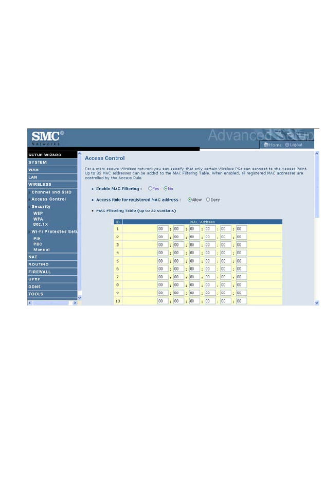
Access Control
Using the Access Control functionality, you can restrict access based on
MAC address. Each PC has a unique identifier known as a Medium Access
Control (MAC) address. With MAC filtering enabled, the computers
whose MAC address you have listed in the filtering table will be able to
connect (or will be denied access) to the Barricade.
W
IRELESS
4-29
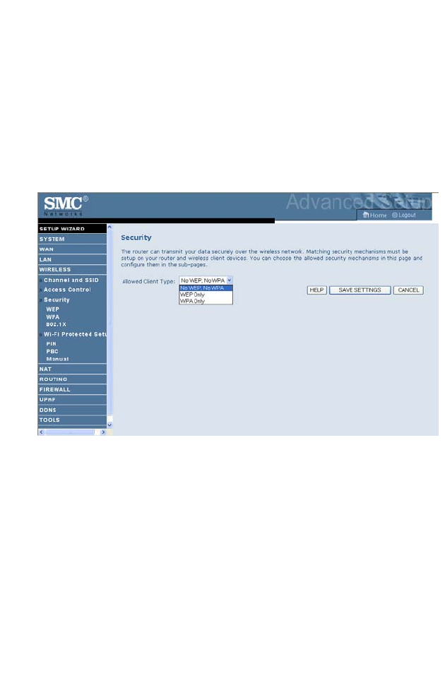
Security
To make your wireless network safe, you should turn on the security
function. The Barricade supports the following security mechanism:
•WEP
•WPA
C
ONFIGURING
THE
B
ARRICADE
4-30
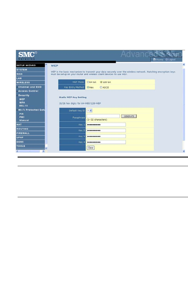
WEP
If you want to use WEP to protect your wireless network, you need to set
the same parameters for the Barricade and all your wireless clients.
To generate the key automatically with passphrase, enter a string of
characters and click the GENERATE button. Select the default key from
the drop-down menu. Click SAVE SETTINGS.
Note: The passphrase can consist of up to 32 alphanumeric characters.
To manually configure the encryption key, enter five hexadecimal pairs of
digits for the 64-bit key, or enter 13 pairs for the 128-bit key.
(A hexadecimal digit is a number or letter in the range 0-9 or A-F.)
Note: WEP protects data transmitted between wireless nodes, but does
not protect any transmissions over your wired network or over the
Internet.
Parameter Description
WEP Mode Select 64 bit or 128 bit key to use for encryption.
Key Entry Method Select Hex or ASCII to use for encryption key.
Static WEP Key
Setting
You may automatically generate encryption keys or manually
enter the keys.
W
IRELESS
4-31
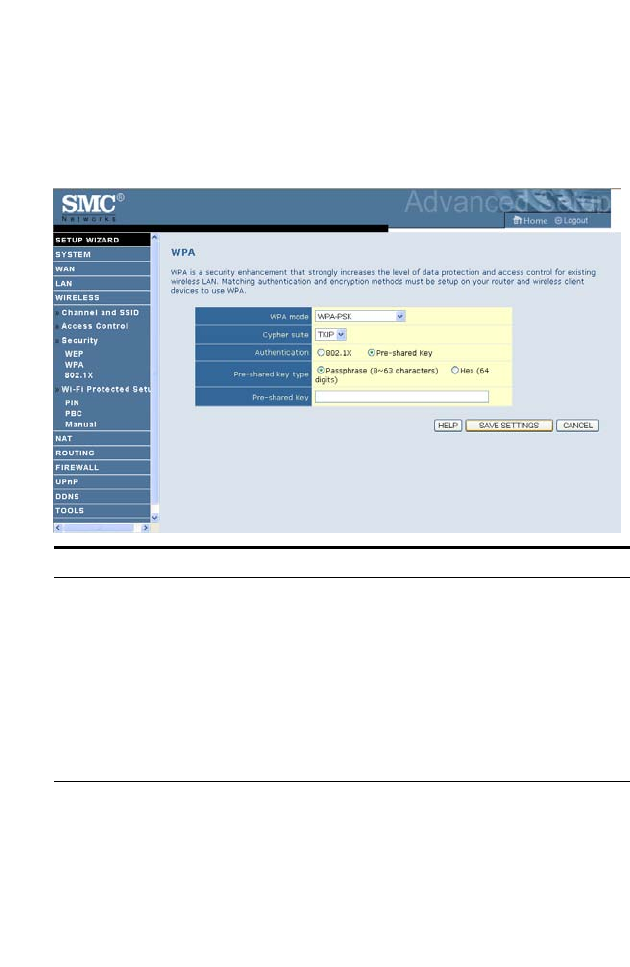
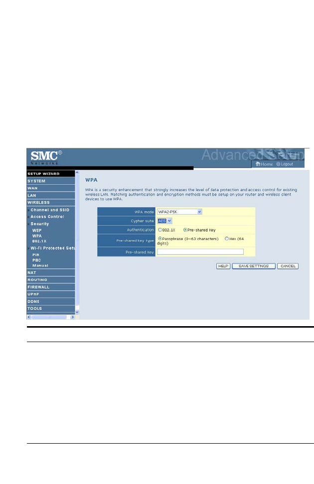
WPA
Wi-Fi Protected Access (WPA) combines temporal key integrity protocol
(TKIP) and 802.1x mechanisms. It provides dynamic key encryption and
802.1x authentication service.
Parameter Description
Authentication Choose 802.1X or Pre-shared Key to use as the authentication
method.
• 802.1X: for the enterprise network with a RADIUS server.
See “802.1X” on page 4-34.
• Pre-shared key: for the SOHO network environment
without an authentication server.
Pre-shared key type Select the key type to be used in the Pre-shared Key.
Pre-shared Key Type in the key here.
C
ONFIGURING
THE
B
ARRICADE
4-32
WPA2
WPA2 is a product certification that is available through the Wi-Fi
Alliance. WPA2 certifies that wireless equipment is compatible with the
IEEE 802.11i standard. The WPA2 product certification formally replaces
Wired Equivalent Privacy (WEP) and the other security features of the
original IEEE 802.11 standard. The goal of WPA2 certification is to
support the additional mandatory security features of the IEEE 802.11i
standard that are not already included for products that support WPA.
Parameter Description
Authentication Choose 802.1X or Pre-shared Key to use as the authentication
method.
• 802.1X: for the enterprise network with a RADIUS server.
See “802.1X” on page 4-34.
• Pre-shared key: for the SOHO network environment
without an authentication server.
Pre-shared key type Select the key type to be used in the Pre-shared Key.
Pre-shared Key Type in the key here.
W
IRELESS
4-33
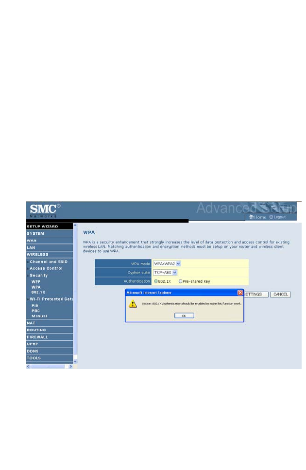
WPA+WPA2
Wi-Fi Protected Access (WPA) combines temporal key integrity protocol
(TKIP) and 802.1x mechanisms. It provides dynamic key encryption and
802.1x authentication service.
Wi-Fi Protected Access 2 (WPA2) is a product certification that is available
through the Wi-Fi Alliance. WPA2 certifies that wireless equipment is
compatible with the IEEE 802.11i standard. The WPA2 product
certification formally replaces Wired Equivalent Privacy (WEP) and the
other security features of the original IEEE 802.11 standard. The goal of
WPA2 certification is to support the additional mandatory security features
of the IEEE 802.11i standard that are not already included for products
that support WPA.
C
ONFIGURING
THE
B
ARRICADE
4-34
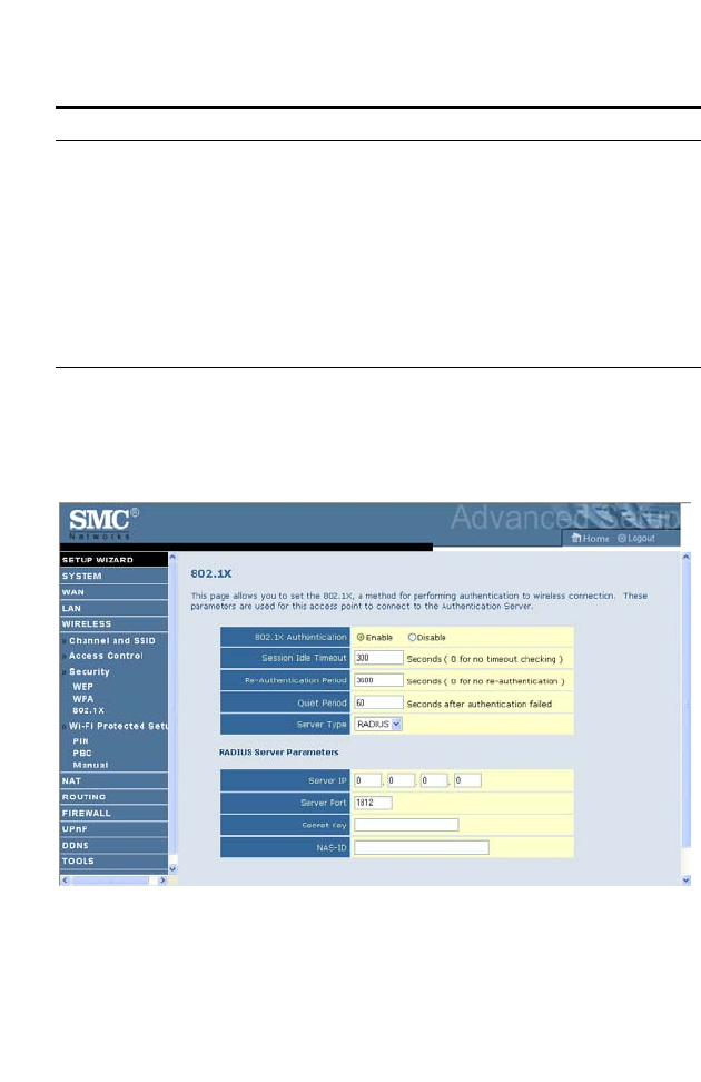
802.1X
If 802.1x is used in your network, then you should enable this function for
the Barricade.
Parameter Description
Authentication Choose 802.1X or Pre-shared Key to use as the
authentication method.
• 802.1X: for the enterprise network with a RADIUS server.
See “802.1X” on page 4-34.
• Pre-shared key: for the SOHO network environment
without an authentication server.
Pre-shared key type Select the key type to be used in the Pre-shared Key.
Pre-shared Key Type in the key here.

W
IRELESS
4-35
Parameter Description
Authentication Enable 802.1x authentication.
Session Idle
Timeout
Defines a maximum period of time for which the connection is
maintained during inactivity.
Re-Authentication
Period
Defines a maximum period of time for which the
authentication server will dynamically re-assign a session key to
a connected client.
Quiet Period Defines a maximum period of time for which the ADSL Router
will wait between failed authentications.
Server Type The Server Type of your authentication server is RADIUS.
RADIUS Server Parameters
Server IP The IP address of your authentication server.
Server Port The port used for the authentication service.
Secret Key The secret key shared between the authentication server and its
clients.
NAS-ID Defines the request identifier of the Network Access Server.
C
ONFIGURING
THE
B
ARRICADE
4-36
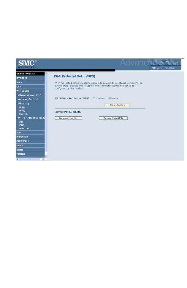
Wi-Fi Protected Setup (WPS)
The Barricade was implemented with the ease-of-use Wi-Fi Protected
Setup (WPS). WPS makes a secure wireless network much easier to achieve
by using an eight-digit PIN number and the Push Button Control (PBC).
Check Enable and click SAVE SETTINGS.
Pressing Generate New PIN creates a new Current PIN number.
Pressing Restore Default PIN sets the PIN code to the factory default
number.
Take the following steps for easy network security settings.
W
IRELESS
4-37
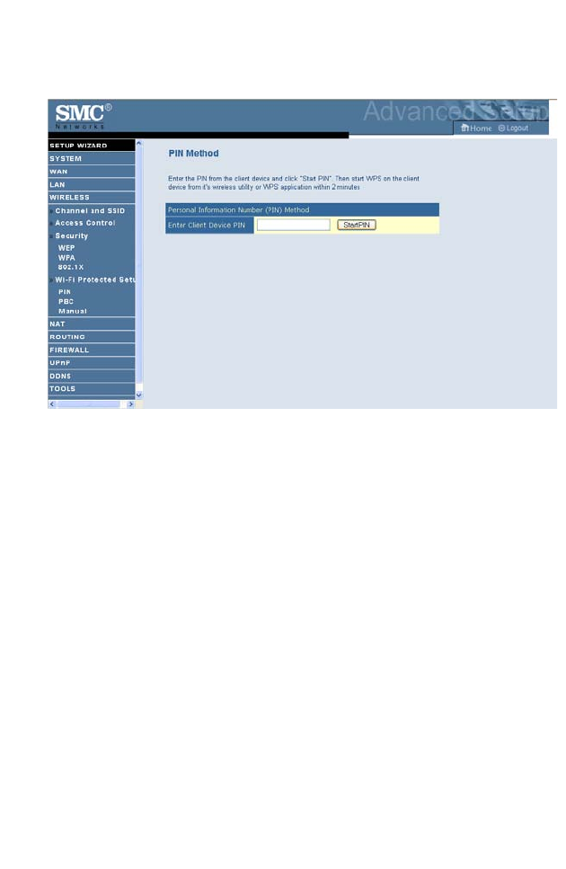
PIN Code Setup
1. Power on your client device supporting WPS PIN code method.
2. Start WPS PIN process on client device. For instructions on how to do
this refer to the user manual of the client device.
3. Enter the PIN code of client device.
Note: The PIN code is generally printed on the bottom of the unit or
displayed in the configuration utility.
4. Click the Start PIN button on the screen.
C
ONFIGURING
THE
B
ARRICADE
4-38
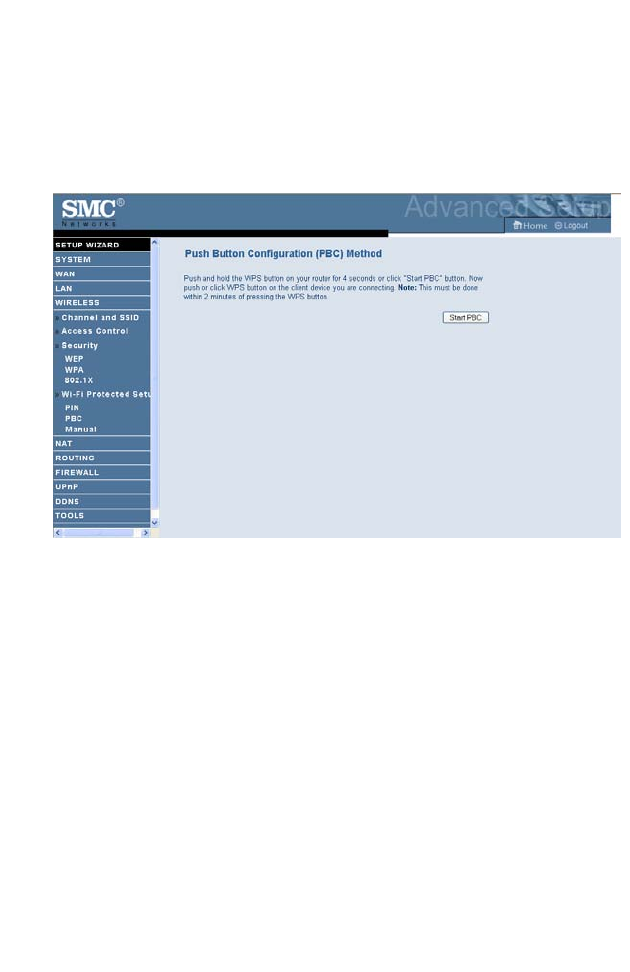
Push Button Configuration (PBC) Method
To achieve successful WPS connection, you can use one of the following
ways: (1) push and hold the WPS button on your Barricade, or (2) click the
Start PBC button on this screen.
1. Power on your network devices such as an access point and client
network devices.
2. Press the WPS button for 4 seconds, or click the Start PBC button on
the screen.
3. Press the WPS button or click the PBC button on your client devices
of your network.
Note: This connection procedure must be done within 2 minutes after
pressing the WPS button on the Barricade.
W
IRELESS
4-39
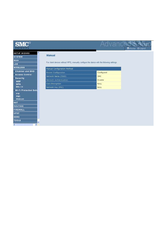
Manual
For client devices without WPS, manually configure the device as displayed
on the screen.
C
ONFIGURING
THE
B
ARRICADE
4-40
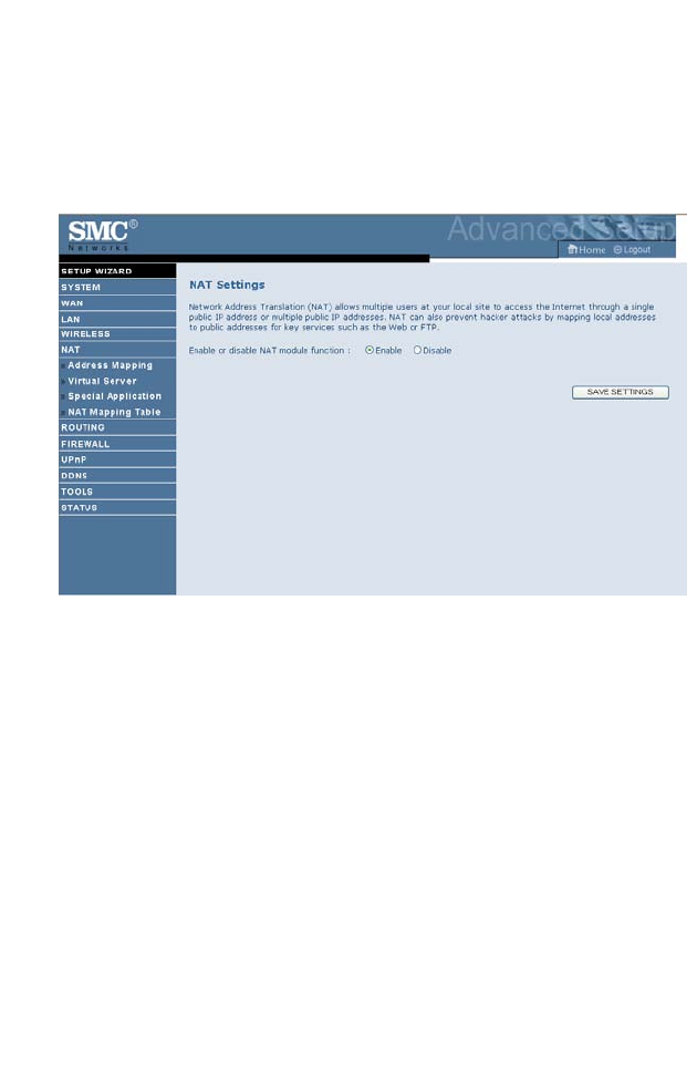
NAT
Network Address Translation allows multiple users to access the Internet
sharing one public IP.
NAT
4-41
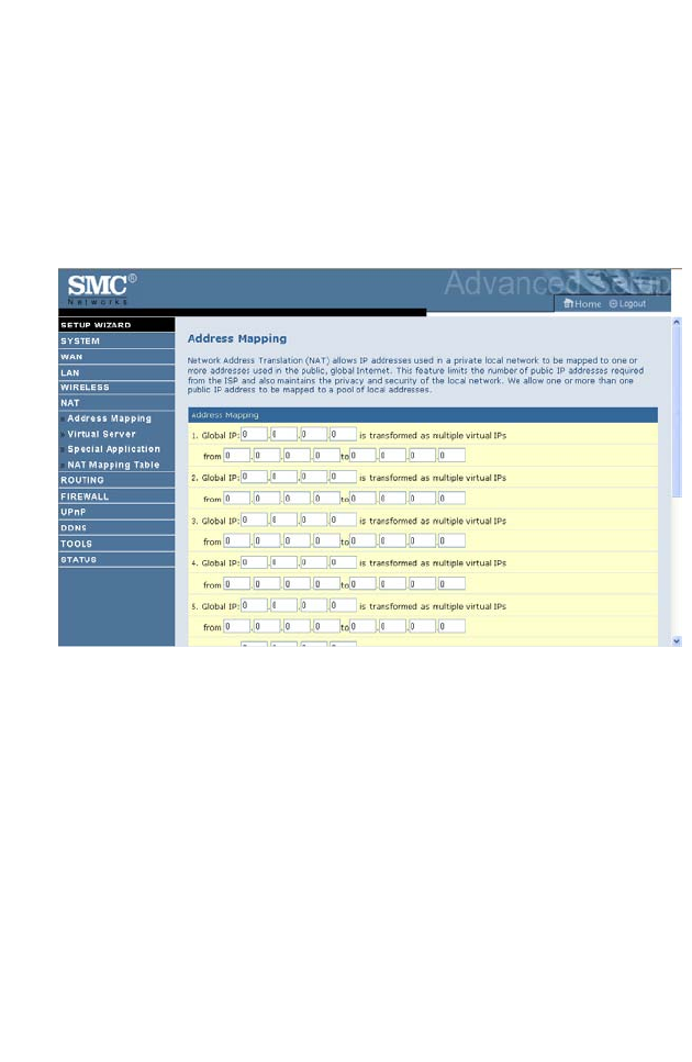
Address Mapping
Allows one or more public IP addresses to be shared by multiple internal
users. This also hides the internal network for increased privacy and
security. Enter the Public IP address you wish to share into the Global IP
field. Enter a range of internal IPs that will share the global IP into the
“from” field.
C
ONFIGURING
THE
B
ARRICADE
4-42
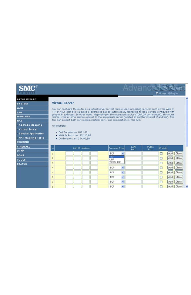
Virtual Server
If you configure the ADSL Router as a virtual server, remote users
accessing services such as web or FTP at your local site via public IP
addresses can be automatically redirected to local servers configured with
private IP addresses. In other words, depending on the requested service
(TCP/UDP port number), the ADSL Router redirects the external service
request to the appropriate server (located at another internal IP address).
For example, if you set Type/Public Port to TCP/80 (HTTP or web) and
the Private IP/Port to 192.168.2.2/80, then all HTTP requests from
outside users will be transferred to 192.168.2.2 on port 80. Therefore, by
just entering the IP address provided by the ISP, Internet users can access
the service they need at the local address to which you redirect them.
The more common TCP service ports include:
HTTP: 80, FTP: 21, Telnet: 23, and POP3: 110.
A list of ports is maintained at the following link:
http://www.iana.org/assignments/port-numbers.
NAT
4-43
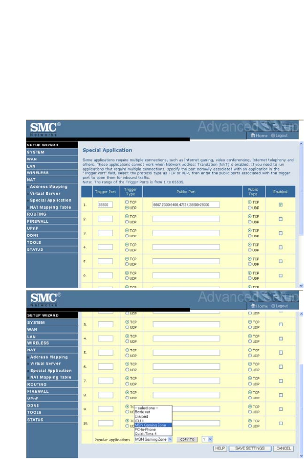
Special Application
Some applications require multiple connections, such as Internet gaming,
video-conferencing, and Internet telephony. These applications may not
work when Network Address Translation (NAT) is enabled. If you need to
run applications that require multiple connections, use these screens to
specify the additional public ports to be opened for each application.
C
ONFIGURING
THE
B
ARRICADE
4-44
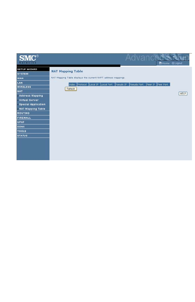
NAT Mapping Table
This screen displays the current NAPT (Network Address Port
Translation) address mappings.
NAT Mapping Table displays the current NAPT address mappings. The
NAT address mappings are listed 20 lines per page, click the control
buttons to move forwards and backwards. As the NAT mapping is
dynamic, a Refresh button is provided to refresh the NAT Mapping Table
with the mots updated values.
The content of the NAT Mapping Table is described as follows.
• Protocol - protocol of the flow.
• Local IP - local (LAN) host’s IP address for the flow.
• Local Port - local (LAN) host’s port number for the flow.
•Pseudo IP - translated IP address for the flow.
• Pseudo Port - translated port number for the flow.
• Peer IP - remote (WAN) host’s IP address for the flow.
• Peer Port - remote (WAN) host’s port number for the flow.
R
OUTING
4-45
Routing
These screens define routing related parameters, including static routes and
RIP (Routing Information Protocol) parameters.
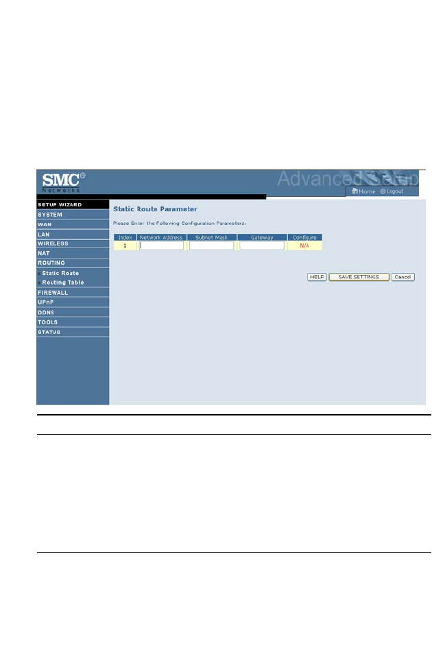
Static Route
Click Add to add a new static route to the list, or check the box of an
already entered route and click Modify. Clicking Delete will remove an
entry from the list.
Parameter Description
Index Check the box of the route you wish to delete or modify.
Network Address Enter the IP address of the remote computer for which
to set a static route.
Subnet Mask Enter the subnet mask of the remote network for which
to set a static route.
Gateway Enter the WAN IP address of the gateway to the remote
network.
C
ONFIGURING
THE
B
ARRICADE
4-46
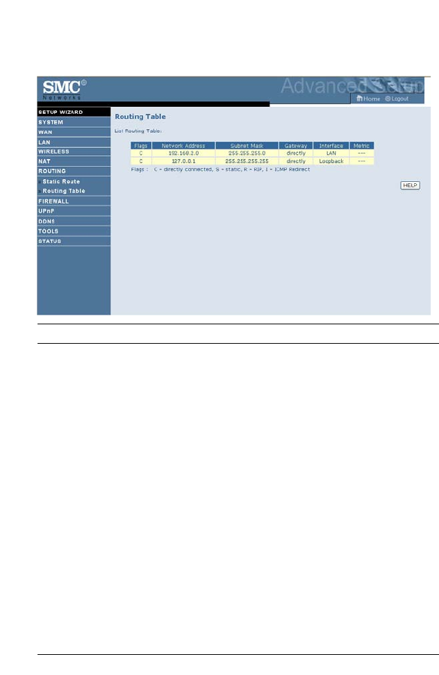
Routing Table
Parameter Description
Flags Indicates the route status:
C = Direct connection on the same subnet.
S = Static route.
R = RIP (Routing Information Protocol) assigned route.
I = ICMP (Internet Control Message Protocol) Redirect route.
Network Address Destination IP address.
Netmask The subnetwork associated with the destination.
This is a template that identifies the address bits in the
destination address used for routing to specific subnets. Each bit
that corresponds to a “1” is part of the subnet mask number;
each bit that corresponds to “0” is part of the host number.
Gateway The IP address of the router at the next hop to which frames are
forwarded.
Interface The local interface through which the next hop of this route is
reached.
Metric When a router receives a routing update that contains a new or
changed destination network entry, the router adds 1 to the
metric value indicated in the update and enters the network in
the routing table.

F
IREWALL
4-47
Firewall
The Barricade Router’s firewall inspects packets at the application layer,
maintains TCP and UDP session information including time-outs and the
number of active sessions, and provides the ability to detect and prevent
certain types of network attacks.
Network attacks that deny access to a network device are called
Denial-of-Service (DoS) attacks. DoS attacks are aimed at devices and
networks with a connection to the Internet. Their goal is not to steal
information, but to disable a device or network so users no longer have
access to network resources.
The Barricade protects against the following DoS attacks: IP Spoofing,
Land Attack, Ping of Death, IP with zero length, Smurf Attack, UDP port
loopback, Snork Attack, TCP null scan, and TCP SYN flooding.
(For details see“Intrusion Detection,” page 4-54.)
The firewall does not significantly affect system performance, so we advise
enabling the function to protect your network.
Select Enable and click the SAVE SETTINGS button.
C
ONFIGURING
THE
B
ARRICADE
4-48
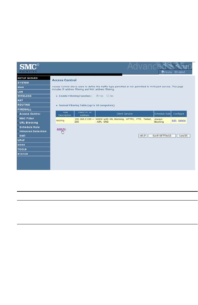
Access Control
Access Control allows users to define the outgoing traffic permitted or
not-permitted through the WAN interface. The default is to permit all
outgoing traffic.
The following items are on the Access Control screen:
Parameter Description
Enable Filtering
Function
Enable or Disable Access control function.
Normal Filtering Table Displays descriptive list of Filtering rules defined.
F
IREWALL
4-49
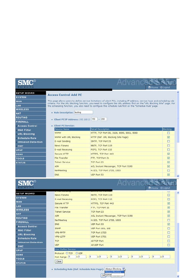
To create a new access control rule:
1. Click Add PC on the Access Control screen. The Access Control Add
PC screen will appear.
2. Define the appropriate settings for client PC services.
3. Click OK and then click SAVE SETTINGS to save your settings.
C
ONFIGURING
THE
B
ARRICADE
4-50
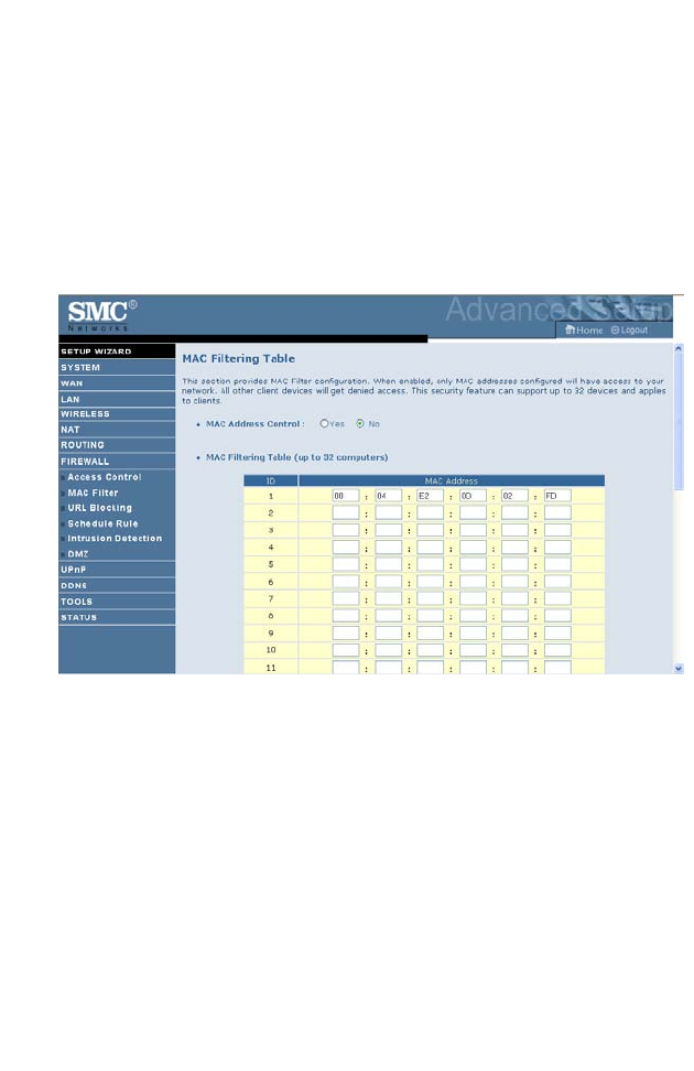
MAC Filter
The MAC Filter allows you to define what client PC’s can access the
Internet. When enabled only the MAC addresses defined in the MAC
Filtering table will have access to the Internet. All other client devices will
be denied access.
You can enter up to 32 MAC addresses in this table.
1. MAC Address Control: select enable or disable.
2. MAC Filtering Table: enter the MAC address in the space provided.
F
IREWALL
4-51
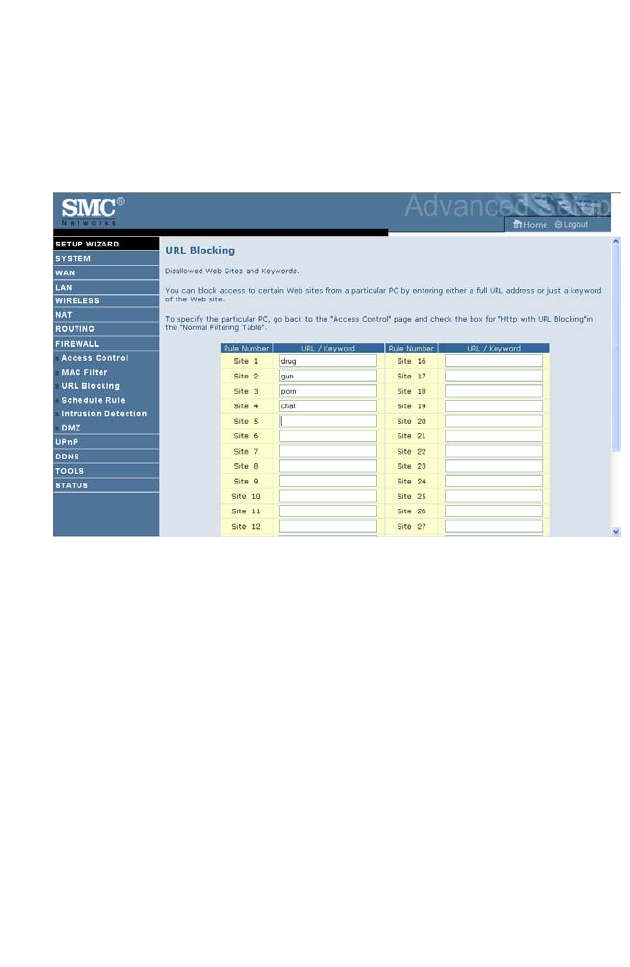
URL Blocking
The ADSL Router allows the user to block access to web sites by entering
either a full URL address or just a keyword. This feature can be used to
protect children from accessing violent or pornographic web sites.
You can define up to 30 sites here.

C
ONFIGURING
THE
B
ARRICADE
4-52
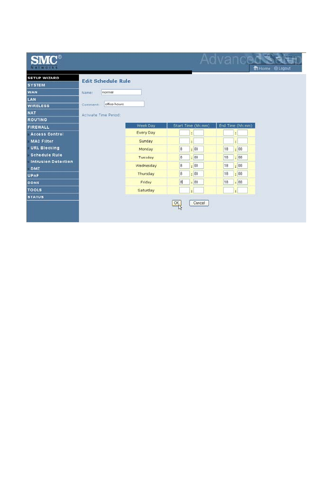
Schedule Rule
You may filter Internet access for local clients based on rules. Each access
control rule may be activated at a scheduled time. Define the schedule on
the Schedule Rule screen, and apply the rule on the Access Control screen.
F
IREWALL
4-53
Follow these steps to add a schedule rule:
1. Click Add Schedule Rule on the Schedule Rule screen. The Edit
Schedule Rule screen will appear.
2. Define the appropriate settings for a schedule rule.
3. Click OK and then click SAVE SETTINGS to save your settings.
C
ONFIGURING
THE
B
ARRICADE
4-54
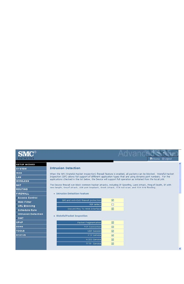
Intrusion Detection
• Intrusion Detection Feature
Stateful Packet Inspection (SPI) and Anti-DoS firewall protection
(Default: Enabled) — The Intrusion Detection Feature of the Barricade
Router limits access for incoming traffic at the WAN port. When the SPI
feature is turned on, all incoming packets will be blocked except for those
types marked in the Stateful Packet Inspection section.
RIP Defect (Default: Enabled) — If an RIP request packet is not
acknowledged to by the router, it will stay in the input queue and not be
released. Accumulated packets could cause the input queue to fill, causing
severe problems for all protocols. Enabling this feature prevents the
packets from accumulating.
Discard Ping to WAN (Default: Disabled) — Prevent a ping on the
Barricade’s WAN port from being routed to the network.
Scroll down to view more information.
F
IREWALL
4-55
•Stateful Packet Inspection
This is called a “stateful” packet inspection because it examines the
contents of the packet to determine the state of the communications; i.e., it
ensures that the stated destination computer has previously requested the
current communication. This is a way of ensuring that all communications
are initiated by the recipient computer and are taking place only with

C
ONFIGURING
THE
B
ARRICADE
4-56
sources that are known and trusted from previous interactions. In addition
to being more rigorous in their inspection of packets, stateful inspection
firewalls also close off ports until connection to the specific port is
requested.
When particular types of traffic are checked, only the particular type of
traffic initiated from the internal LAN will be allowed. For example, if the
user only checks “FTP Service” in the Stateful Packet Inspection section,
all incoming traffic will be blocked except for FTP connections initiated
from the local LAN.
Stateful Packet Inspection allows you to select different application types
that are using dynamic port numbers. If you wish to use the Stateful Packet
Inspection (SPI) to block packets, click on the Yes radio button in the
“Enable SPI and Anti-DoS firewall protection” field and then check the
inspection type that you need, such as Packet Fragmentation, TCP
Connection, UDP Session, FTP Service, H.323 Service, or TFTP Service.
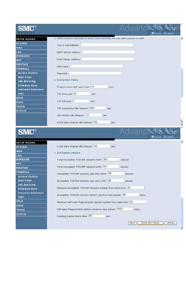
•When hackers attempt to enter your network, we can alert you by
e-mail
Enter your email address. Specify your SMTP and POP3 servers, user
name, and password.

F
IREWALL
4-57
•Connection Policy
Enter the appropriate values for TCP/UDP sessions as described in the
following table.
Parameter Defaults Description
Fragmentation
half-open wait
10 sec Configures the number of seconds that a packet
state structure remains active. When the timeout
value expires, the router drops the unassembled
packet, freeing that structure for use by another
packet.
TCP SYN wait 30 sec Defines how long the software will wait for a
TCP session to synchronize before dropping the
session.
TCP FIN wait 5 sec Specifies how long a TCP session will be
maintained after the firewall detects a FIN
packet.
TCP connection
idle timeout
3600
seconds
(1 hour)
The length of time for which a TCP session will
be managed if there is no activity.
UDP session idle
timeout
30 sec The length of time for which a UDP session will
be managed if there is no activity.
H.323 data channel
idle timeout
180 sec The length of time for which an H.323 session
will be managed if there is no activity.

C
ONFIGURING
THE
B
ARRICADE
4-58
•DoS Criteria and Port Scan Criteria
Set up DoS and port scan criteria in the spaces provided (as shown below).
Note: The firewall does not significantly affect system performance, so
we advise enabling the prevention features to protect your
network.
Parameter Defaults Description
Total incomplete
TCP/UDP sessions
HIGH
300
sessions
Defines the rate of new unestablished sessions
that will cause the software to start deleting
half-open sessions.
Total incomplete
TCP/UDP sessions
LOW
250
sessions Defines the rate of new unestablished sessions
that will cause the software to stop deleting half-
open sessions.
Incomplete
TCP/UDP sessions
(per min) HIGH
250
sessions Maximum number of allowed incomplete
TCP/UDP sessions per minute.
Incomplete
TCP/UDP sessions
(per min) LOW
200
sessions Minimum number of allowed incomplete
TCP/UDP sessions per minute.
Maximum incomplete
TCP/UDP sessions
number from same
host
10 Maximum number of incomplete TCP/UDP
sessions from the same host.
Incomplete
TCP/UDP sessions
detect sensitive time
period
300
msec Length of time before an incomplete
TCP/UDP session is detected as incomplete.
Maximum half-open
fragmentation packet
number from same
host
30 Maximum number of half-open fragmentation
packets from the same host.
Half-open
fragmentation detect
sensitive time period
10000
msec Length of time before a half-open
fragmentation session is detected as half-open.
Flooding cracker
block time
300
second Length of time from detecting a flood attack to
blocking the attack.
F
IREWALL
4-59
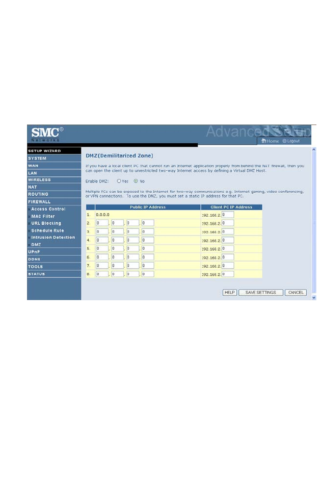
DMZ
If you have a client PC that cannot run an Internet application properly
from behind the firewall, you can open the client up to unrestricted two-
way Internet access. Enter the IP address of a DMZ (Demilitarized Zone)
host on this screen. Adding a client to the DMZ may expose your local
network to a variety of security risks, so only use this option as a last resort.
C
ONFIGURING
THE
B
ARRICADE
4-60
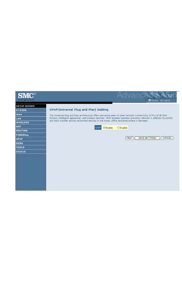
UPnP
The Universal Plug and Play architecture offers pervasive peer-to-peer
network connectivity of PCs of all form factors, intelligent appliances, and
wireless devices.
UPnP enables seamless proximity network in addition to control and data
transfer among networked devices in the office, home and everywhere
within your network.
UPnP allows the device to automatically:
• join a network
• obtain an IP address
• convey its capabilities and learn about the presence and capabilities of
other devices.
Check the Enable radio button to activate this function.
DDNS
4-61
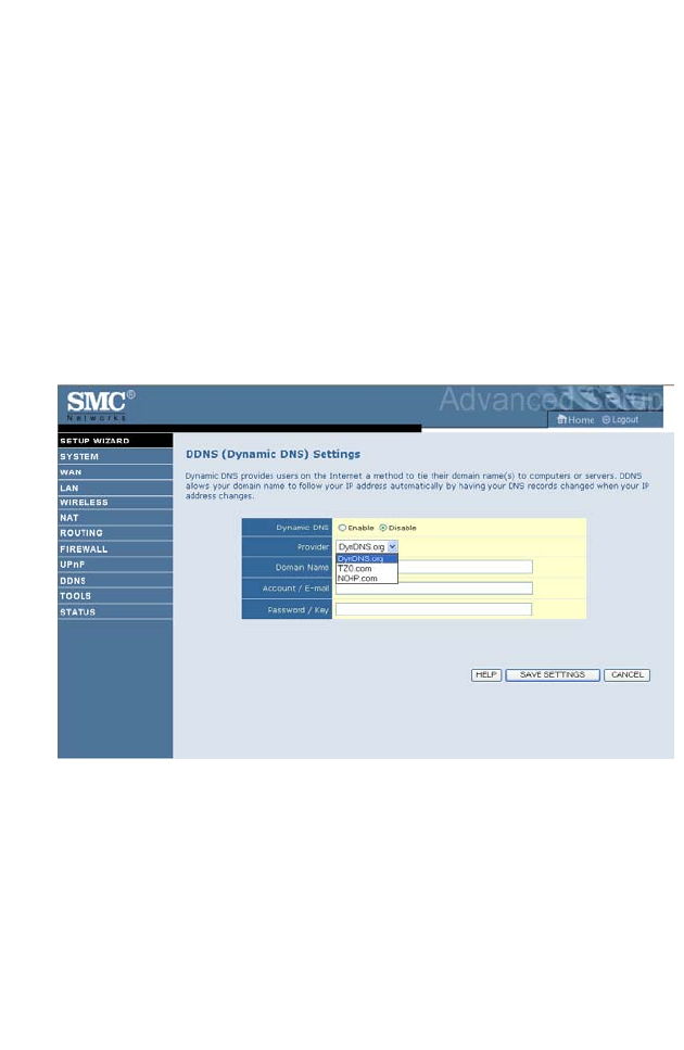
DDNS
Dynamic Domain Name Service (DDNS) provides users on the Internet
with a method to tie their domain name to a computer or server. DDNS
allows your domain name to follow your IP address automatically by
having your DNS records changed when your IP address changes.
This DNS feature is powered by DynDNS.org or TZO.com. With a
DDNS connection you can host your own web site, email server, FTP site,
and more at your own location even if you have a dynamic IP address.
C
ONFIGURING
THE
B
ARRICADE
4-62
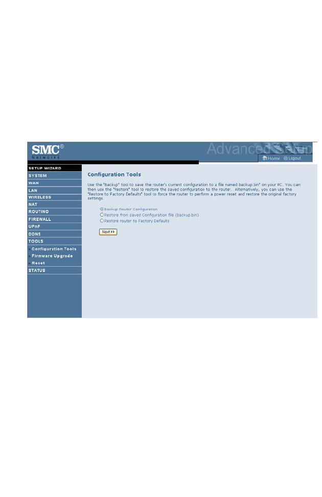
Tools
Use the Tools menu to backup the current configuration, restore a
previously saved configuration, update firmware, and reset the Barricade.
Configuration Tools
Choose a function and click Next.
• Backup Router Configuration: this allows you to save the Barricade’s
configuration to a file.
• Restore from saved Configuration file: this function is used to restore
the previously saved backup configuration file.
• Restore router to Factory Defaults: this resets the Barricade back to the
original default settings.
T
OOLS
4-63
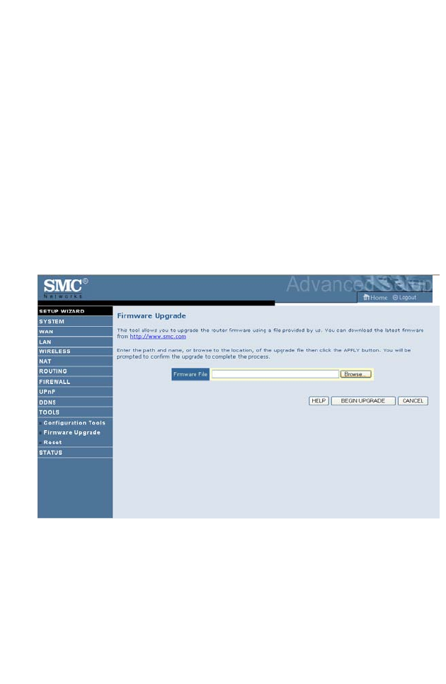
Firmware Upgrade
Use this screen to update the firmware or user interface to the latest
versions.
1. Download the upgrade file from the SMC web site first, and save it to
your hard drive.
2. Then click Browse... to look for the downloaded file. Click BEGIN
UPGRADE.
Check the Status screen Information section to confirm that the upgrade
process was successful.
C
ONFIGURING
THE
B
ARRICADE
4-64
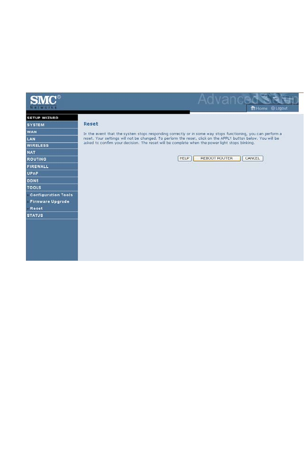
Reset
Click REBOOT ROUTER to reset the ADSL Router. The reset will be
complete when the power LED stops blinking.
If you perform a reset from this screen, the configurations will not be
changed back to the factory default settings.
Note: If you use the Reset button on the back panel, the Barricade
performs a power reset. If the button is pressed for over
10 seconds, all the LEDs will illuminate and the factory default
settings will be restored.
T
OOLS
4-65
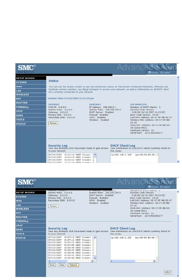
STATUS
The Status screen displays WAN/LAN connection status, firmware, and
hardware version numbers, illegal attempts to access your network, as well
as information on DHCP clients connected to your network. The security
log may be saved to a file by clicking Save and choosing a location.
Scroll down to view more information on the Status screen.

C
ONFIGURING
THE
B
ARRICADE
4-66
The following items are included on the Status screen:
Parameter Description
INTERNET Displays WAN connection type and status.
Renew Click on this button to establish a connection to the WAN.
GATEWAY Displays system IP settings, as well as DHCP Server and
Firewall status.
INFORMATION Displays the number of attached clients, the firmware versions,
the physical MAC address for each media interface and for the
ADSL Router, as well as the hardware version and serial
number.
Security Log Displays attempts to access your network.
Save Click on this button to save the security log file.
Clear Click on this button to delete the access log.
Refresh Click on this button to refresh the screen.
DHCP Client Log Displays information on DHCP clients on your network.

F
INDING
THE
MAC
ADDRESS
OF
A
N
ETWORK
C
ARD
4-67
Finding the MAC address of a Network Card
WINDOWS NT4/2000/XP
Click Start/Programs/Command Prompt. Type “ipconfig /all” and press
“ENTER”.
The MAC address is listed as the “Physical Address.”
MACINTOSH
Click System Preferences/Network.
The MAC address is listed as the “Ethernet Address” on the TCP/IP tab.
LINUX
Run the command “/sbin/ifconfig.”
The MAC address is the value after the word “HWaddr.”

C
ONFIGURING
THE
B
ARRICADE
4-68

A-1
A
PPENDIX
A
T
ROUBLESHOOTING
This section describes common problems you may encounter and possible
solutions to them. The Barricade can be easily monitored through panel
indicators to identify problems.
Troubleshooting Chart
Symptom Action
LED Indicators
Power LED is
off
• Check connections between the Barricade, the
external power supply, and the wall outlet.
• If the power indicator does not turn on when the
power cord is plugged in, you may have a problem
with the power outlet, power cord, or external power
supply. However, if the unit powers off after running
for a while, check for loose power connections, power
losses, or surges at the power outlet. If you still cannot
isolate the problem, then the external power supply
may be defective. In this case, contact Technical
Support for assistance.

T
ROUBLESHOOTING
A-2
LED Indicators
LAN LED is
Off
• Verify that the Barricade and attached device are
powered on.
• Be sure the cable is plugged into both the Barricade
and the corresponding device.
• Verify that the proper cable type is used and that its
length does not exceed the specified limits.
• Be sure that the network interface on the attached
device is configured for the proper communication
speed and duplex mode.
• Check the adapter on the attached device and cable
connections for possible defects. Replace any
defective adapter or cable if necessary.
Network Connection Problems
Cannot ping the
Barricade from
the attached
LAN, or the
Barricade cannot
ping any device
on the attached
LAN
• Verify that the IP addresses are properly configured.
For most applications, you should use the Barricade’s
DHCP function to dynamically assign IP addresses to
hosts on the attached LAN. However, if you manually
configure IP addresses on the LAN, verify that the
same network address (network component of the IP
address) and subnet mask are used for both the
Barricade and any attached LAN devices.
• Be sure the device you want to ping (or from which
you are pinging) has been configured for TCP/IP.
Troubleshooting Chart
Symptom Action

T
ROUBLESHOOTING
A-3
Management Problems
Cannot connect
using the web
browser
• Be sure to have configured the Barricade with a valid
IP address, subnet mask, and default gateway.
• Check that you have a valid network connection to the
Barricade and that the port you are using has not been
disabled.
• Check the network cabling between the management
station and the Barricade.
Forgot or lost
the password
•Press the Reset button on the rear panel (holding it
down for at least six seconds) to restore the factory
defaults.
Troubleshooting Chart
Symptom Action

T
ROUBLESHOOTING
A-4
Wireless Problems
A wireless PC
cannot associate
with the
Barricade.
• Make sure the wireless PC has the same SSID settings
as the Barricade.
See “Channel and SSID” on page 4-26.
• You need to have the same security settings on the
clients and the Barricade. See “Security” on page 4-29.
The wireless
network is often
interrupted.
• Move your wireless PC closer to the Barricade to find
a better signal. If the signal is still weak, change the
angle of the antenna.
• There may be interference, possibly caused by
microwave ovens or wireless phones. Change the
location of the possible sources of interference or
change the location of the Barricade.
• Change the wireless channel on the Barricade. See
“Channel and SSID” on page 4-26.
• Check that the antenna, connectors, and cabling are
firmly connected.
The Barricade
cannot be
detected by a
wireless client.
• The distance between the Barricade and wireless PC is
too great.
• Make sure the wireless PC has the same SSID and
security settings as the Barricade. See “Channel and
SSID” on page 4-26 and “Security” on page 4-29.
Troubleshooting Chart
Symptom Action

B-1
A
PPENDIX
B
C
ABLES
Ethernet Cable
Caution:
Do not plug a phone jack connector into an RJ-45 port.
For
Ethernet connections, use only twisted-pair cables with RJ-45
connectors that conform to FCC standards.
Specifications
Wiring Conventions
For Ethernet connections, a twisted-pair cable must have two pairs of
wires. Each wire pair is identified by two different colors. For example, one
wire might be red and the other, red with white stripes. Also, an RJ-45
connector must be attached to both ends of the cable.
Cable Types and Specifications
Cable Type Max. Length Connector
10BASE-T Cat. 3, 4, 5 100-ohm UTP 100 m (328 ft) RJ-45
100BASE-TX Cat. 5 100-ohm UTP 100 m (328 ft) RJ-45

C
ABLES
B-2
Each wire pair must be attached to the RJ-45 connectors in a specific
orientation. The following figure illustrates how the pins on an Ethernet
RJ-45 connector are numbered. Be sure to hold the connectors in the same
orientation when attaching the wires to the pins.
Figure B-1. RJ-45 Ethernet Connector Pin Numbers
RJ-45 Port Ethernet Connection
Use the straight-through CAT -5 Ethernet cable provided in the package
to connect the Barricade to your PC. When connecting to other network
devices such as an Ethernet switch, use the cable type shown in the
following table.
Attached Device Port Type Connecting Cable Type
MDI-X Straight-through
MDI Crossover

RJ-45 P
ORT
E
THERNET
C
ONNECTION
B-3
Pin Assignments
With 10BASE-T/100BASE-TX cable, pins 1 and 2 are used for
transmitting data, and pins 3 and 6 for receiving data.
Straight-Through Wiring
If the port on the attached device has internal crossover wiring (MDI-X),
then use straight-through cable.
RJ-45 Pin Assignments
Pin Number Assignment*
1Tx+
2Tx-
3Rx+
6Rx-
* The “+” and “-” signs represent the polarity of the
wires that make up each wire pair.
Straight-Through Cable Pin Assignments
End 1 End 2
1 (Tx+) 1 (Tx+)
2 (Tx-) 2 (Tx-)
3 (Rx+) 3 (Rx+)
6 (Rx-) 6 (Rx-)

C
ABLES
B-4
Crossover Wiring
If the port on the attached device has straight-through wiring (MDI), use
crossover cable.
Crossover Cable Pin Assignments
End 1 End 2
1 (Tx+) 3 (Rx+)
2 (Tx-) 6 (Rx-)
3 (Rx+) 1 (Tx+)
6 (Rx-) 2 (Tx-)

C-1
A
PPENDIX
C
S
PECIFICATIONS
IEEE Standards
IEEE 802.3 10 BASE-T Ethernet
IEEE 802.3u 100 BASE-TX Fast Ethernet
IEEE 802.3, 802.3u, 802.11g, 802.1D
LAN Interface
4 RJ-45 10 BASE-T/100 BASE-TX ports
Auto-negotiates the connection speed to 10 Mbps Ethernet or 100 Mbps
Fast Ethernet, and the transmission mode to half-duplex or full-duplex
WAN Interface
1 RJ-45 port
Indicator Panel
Power, WAN, Online, WLAN, LAN 1~4, WPS
Dimensions
188 x 133 x 33 mm (7.40 x 5.24 x 1.30 in)
Weight
0.285 kg (0.764 lbs)
Input Power
12 V 1 A
DVE EU DSA-12R-AEU 120120, US DSA-12R-AUS 120120
Leader EU MV12-4120100-C5, US MV12-4120100-A1
Power Consumption
8 Watts maximum

S
PECIFICATIONS
C-2
Advanced Features
Dynamic IP Address Configuration – DHCP, DNS
Firewall – Client privileges, hacker prevention and logging,
Stateful Packet Inspection
Virtual Private Network – PPTP, L2TP, IPSec pass-through, VPN
pass-through
Internet Standards
RFC 826 ARP, RFC 791 IP, RFC 792 ICMP, RFC 768 UDP, RFC 793 TCP,
RFC 783 TFTP, RFC 1661 PPP, RFC 1866 HTML, RFC 2068 HTTP
Radio Features
Wireless RF module Frequency Band
802.11n Radio: 2.4GHz
802.11g Radio: 2.4GHz
802.11b Radio: 2.4GHz
USA - FCC
2412~2462MHz (Ch1~Ch11)
Canada - IC
2412~2462MHz (Ch1~Ch11)
Europe - ETSI
2412~2472MHz (Ch1~Ch13)
Japan - STD-T66/STD-33
2412~2484MHz (Ch1~Ch14)
Modulation Type
OFDM, CCK
Operating Channels IEEE 802.11n Compliant:
11 channels (US, Canada, Europe, Japan)
Operating Channels IEEE 802.11g Compliant:
11 channels (US, Canada)
13 channels (Europe, Japan)

S
PECIFICATIONS
C-3
Operating Channels IEEE 802.11b Compliant:
11 channels (US, Canada)
13 channels (Europe)
14 channels (Japan)
Standards Compliance
Safety
LVD
Environmental
CE Mark
Temperature
Operating 0 to 40 °C (32 to 104 °F)
Storage -40 to 70 °C (-40 to 158 °F)
Humidity
5% to 95% (non-condensing)
Vibration
IEC 68-2-36, IEC 68-2-6
Shock
IEC 68-2-29
Drop
IEC 68-2-32

S
PECIFICATIONS
C-4
SMCWBR11-G
SMCWBR14S-N