Arcadyan Technology WN4201E Barricade g 802.11g Wireless PCI Adapter User Manual SMC2602W
Arcadyan Technology Corporation Barricade g 802.11g Wireless PCI Adapter SMC2602W
User Manual

Barricade g
802.11g Wireless PCI Adapter
TM
SMCWPCI-G2

20 Mason
Irvine, CA 92618
Phone: (949) 679-8000
Barricade™ g 802.11g Wireless
PCI Adapter
User Guide
The easy way to make all your network connections
January 2008
Pub No: R01

Copyright
Information furnished by SMC Networks, Inc. (SMC) is believed to be accurate and reliable.
However, no responsibility is assumed by SMC for its use, nor for any infringements of patents
or other rights of third parties which may result from its use. No license is granted by
implication or otherwise under any patent or patent rights of SMC. SMC reserves the right to
change specifications at any time without notice.
Copyright © 2008 by
SMC Networks, Inc.
20 Mason
Irvine, CA 92618
All rights reserved.
Trademarks:
SMC is a registered trademark; and Barricade is a trademark of SMC Networks, Inc. Other
product and company names are trademarks or registered trademarks of their respective
holders.

i
Compliances
Federal Communication Commission Interference
Statement
This equipment has been tested and found to comply with the limits for a Class B
digital device, pursuant to Part 15 of the FCC Rules. These limits are designed to
provide reasonable protection against harmful interference in a residential
installation. This equipment generates, uses and can radiate radio frequency
energy and, if not installed and used in accordance with the instructions, may
cause harmful interference to radio communications. However, there is no
guarantee that interference will not occur in a particular installation. If this
equipment does cause harmful interference to radio or television reception, which
can be determined by turning the equipment off and on, the user is encouraged to
try to correct the interference by one of the following measures:
• Reorient or relocate the receiving antenna
• Increase the separation between the equipment and receiver
• Connect the equipment into an outlet on a circuit different from that to which the
receiver is connected
• Consult the dealer or an experienced radio/TV technician for help
This device complies with Part 15 of the FCC Rules. Operation is subject to the
following two conditions: (1) This device may not cause harmful interference, and
(2) this device must accept any interference received, including interference that
may cause undesired operation.
FCC Caution: Any changes or modifications not expressly approved by the party
responsible for compliance could void the user’s authority to operate this
equipment.
IMPORTANT NOTE
FCC Radiation Exposure Statement
This equipment complies with FCC radiation exposure limits set forth for an
uncontrolled environment. This equipment should be installed and operated with
minimum distance of 20 cm between the radiator and your body.
This transmitter must not be co-located or operating in conjunction with any other
antenna or transmitter.
2.4GHz operation of this product in the U.S.A. is firmware-limited to channels 1
through 11.

Compliances
ii
IC (Industry Canada) Statement
This device complies with RSS-210 of the Industry Canada Rules.
Operation is subject to the following two conditions:
1) this device may not cause interference and
2) this device must accept any interference, including interference that may cause
undesired operation of the device
This Class B digital apparatus complies with Canadian ICES-003.
Cet appareil numerique de la class B est conforme a la norme NMB-003 du
Canada.
This device has been designed to operate with an antenna having a maximum
gain of 2 dBi. Antenna having a higher gain is strictly prohibited per regulations of
Industry Canada. The required antenna impedance is 50 ohms
To reduce potential radio interference to other users, the antenna type and its gain
should be so chosen that the EIRP is not more than required for successful
communication.
IMPORTANT NOTE:
IC Radiation Exposure Statement:
This equipment complies with Canada radiation exposure limits set forth for
uncontrolled environments. This equipment should be installed and operated with
minimum distance of 20 cm between the radiator and your body.
This transmitter must not be co-located or operating in conjunction with any other
antenna or transmitter.
2.4GHz operation of this product in Canada is firmware-limited to
channels 1 through 11.

Compliances
iii
EC Conformance Declaration
SMC contact for these products in Europe is:
SMC Networks Europe,
Edificio Conata II,
Calle Fructuos Gelabert 6-8, 2, 4a,
08970 - Sant Joan Despi,
Barcelona, Spain
Marking by the above symbol indicates compliance with the Essential
Requirements of the R&TTE Directive of the European Union (1999/5/EC). This
equipment meets the following conformance standards:
EN 300 328
EN 301 489-1
EN 301 489-17
EN 60950

vii
T
ABLE
OF
C
ONTENTS
Barricade™g 802.11g Wireless PCI Adapter . . . . 1
Features . . . . . . . . . . . . . . . . . . . . . . . . . . . . . . . . . . . . . . . . . . . 1
Applications . . . . . . . . . . . . . . . . . . . . . . . . . . . . . . . . . . . . . . . . 2
System Requirements . . . . . . . . . . . . . . . . . . . . . . . . . . . . . . . . 3
Package Checklist . . . . . . . . . . . . . . . . . . . . . . . . . . . . . . . . . . . 4
Hardware Description . . . . . . . . . . . . . . . . . . . . . . . 5
LED Indicators . . . . . . . . . . . . . . . . . . . . . . . . . . . . . . . . . . . . . . 5
Hardware Installation . . . . . . . . . . . . . . . . . . . . . . . 6
Driver and Utility Installation . . . . . . . . . . . . . . . . . 8
Using the Installation Wizard . . . . . . . . . . . . . . . . . . . . . . . . . . . 8
Utility Configuration . . . . . . . . . . . . . . . . . . . . . . . 11
Using the SMCWPCI-G2 Utility Program . . . . . . . . . . . . . . . . . 11
Configuration . . . . . . . . . . . . . . . . . . . . . . . . . . . . . . . . . 12
Link Information . . . . . . . . . . . . . . . . . . . . . . . . . . . . . . . 21
IP Information . . . . . . . . . . . . . . . . . . . . . . . . . . . . . . . . . 23
Site Survey . . . . . . . . . . . . . . . . . . . . . . . . . . . . . . . . . . . 24
Version Information . . . . . . . . . . . . . . . . . . . . . . . . . . . . . 25
Network Configuration and Planning . . . . . . . . . 26
Network Topologies . . . . . . . . . . . . . . . . . . . . . . . . . . . . . . . . . 26
Ad Hoc Wireless LAN . . . . . . . . . . . . . . . . . . . . . . . . . . . 26
Infrastructure Wireless LAN . . . . . . . . . . . . . . . . . . . . . . 27
Setting the Communication Domain . . . . . . . . . . . . . . . . . . . . . 28
Stationary Wireless PCs . . . . . . . . . . . . . . . . . . . . . . . . . 28
Roaming Wireless PCs . . . . . . . . . . . . . . . . . . . . . . . . . . 28

T
ABLE
OF
C
ONTENTS
viii
Troubleshooting . . . . . . . . . . . . . . . . . . . . . . . . . .30
Adapter Installation Problems . . . . . . . . . . . . . . . . . . . . . . . . . 30
Network Connection Problems . . . . . . . . . . . . . . . . . . . . . . . . 31
SMCWPCI-G2 Maximum Distance Table . . . . . . . . . . . 32
Specifications . . . . . . . . . . . . . . . . . . . . . . . . . . . .34

1
BARRICADE™G 802.11G
WIRELESS PCI ADAPTER
SMC’s Barricade™g 802.11g Wireless PCI Adapter
(SMCWPCI-G2) is a 54 Mbps wireless network adapter for
desktop PCs that seamlessly integrates with existing Ethernet
networks. This solution offers a high data rate and reliable
wireless connectivity with considerable cost savings over wired
LANs (which include long-term maintenance overhead for
cabling). Just install enough wireless access points to cover your
network area, plug wireless cards into your desktop computers,
and start networking.
Using this card in conjunction with SMCWEB-G wireless access
points, you can create an instant network that integrates
seamlessly with 10/100 Mbps Ethernet LANs. Moving or
expanding your network is as easy as moving or installing
additional access points – no wires!
Features
•Up to 54 Mbps data rate
•Wireless connection without the hassles and cost of cabling
•Greater flexibility to locate or move networked computers
•Integrates with or replaces wired LANs at dramatically lower
cost than wired alternatives
•Seamless connectivity to wired Ethernet LANs augments
existing networks quickly and easily

APPLICATIONS
2
•Easy installation
•Working range up to 60 m (197 ft) at 54 Mbps, or up to 350 m
(1,155 ft) at 1 Mbps for indoor communications
•Direct Sequence Spread-Spectrum (DSSS) technology
provides robust, interference-resistant and secure wireless
connection
•Supports a wide range of systems
(Windows 98SE/Me/2000/XP)
•Plug-and-Play
•Provides a user-friendly interface for configuration
•Enhances your network security with WEP and WPA/WPA2
data encryption
•Removable antenna
Applications
BarricadeTM g wireless products offer fast and reliable network
access for wireless clients in applications such as:
• Remote access to corporate network information
Email, file transfer, and terminal emulation
• Difficult-to-wire environments
Historic or old buildings, asbestos installations, and open
areas where wiring is difficult to employ
• Frequently changing environments
Retailers, manufacturers, and banks who frequently
rearrange the workplace and change location

SYSTEM REQUIREMENTS
3
• Temporary LANs for special projects or peak time
Trade shows, exhibitions, and construction sites that need to
set up for a short time period. Retailers, airline, and shipping
companies who need additional workstations for peak
periods. Auditors who require workgroups at customer sites
• Access to databases for mobile workers
Doctors, nurses, retailers, office workers who need access to
databases while being mobile in a hospital, retail store, office,
campus etc.
• SOHO users
SOHO (Small Office Home Office) users who need quick and
easy installation of a small computer network
System Requirements
Before you install the Wireless PCI Adapter, check your system
for the following requirements:
•A computer with a bus-mastered PCI slot, and PCI card and
socket services compliant with revision 2.2 of the PCI
specification
•Windows 98SE/Me/2000/XP (have the Windows OS
installation CD ready for use during driver installation)
•A minimum of 6 Mbytes of free disk space for installing the
driver and utility program
•Another IEEE 802.11b/g compliant device installed in your
network, such as the SMCWEB-G Wireless Access Point, or
another computer with a wireless adapter

PACKAGE CHECKLIST
4
Package Checklist
The Barricade™g 802.11g Wireless PCI Adapter package
includes:
•1 Barricade™g 802.11g Wireless PCI Adapter
•1 EZ Installation Wizard and Documentation CD
•1 External Antenna
•1 Quick Installation Guide
Please register this product and upgrade the product warranty at
SMC’s web site at www.smc.com
Please inform your dealer if there are any incorrect, missing, or
damaged parts. If possible, retain the carton, including the
original packing materials. Use them again to repack the product
if there is a need to return it for repair.
5
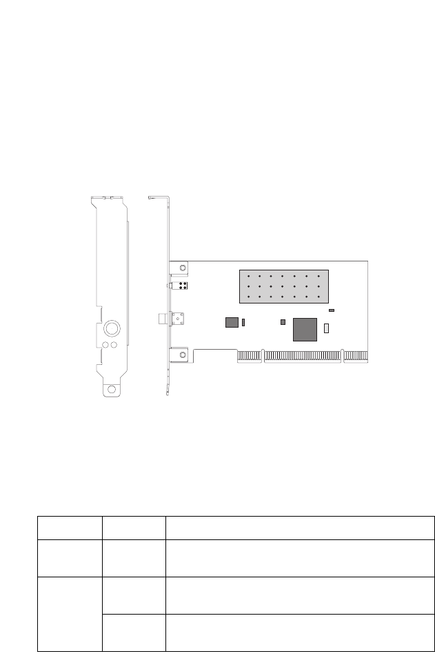
HARDWARE DESCRIPTION
The Wireless PCI Adapter supports up to 54 Mbps connections.
This card is fully compliant with the specifications defined in IEEE
802.11g standard. It is designed to complement PCI Local Bus
computers and supports Windows 98SE/Me/2000/XP.
LED Indicators
The Wireless PCI Adapter includes two status LED indicators, as
described in the following table.
LED Status Description
ACT
(Activity)
Flashing Indicates that the Wireless PCI Adapter is
browsing active access points.
PWR
(Power/
Link)
On Indicates a valid connection with an access
point.
Flashing Indicates that the Wireless PCI Adapter is
operating in the Ad Hoc mode.
PWR
ANT
ACT

6
HARDWARE INSTALLATION
Warning:
• If you are installing in an older computer model,
upgrade the BIOS to the latest version.
• Network cards are sensitive to static electricity. To
protect the card, avoid touching its electrical
components and always touch the metal chassis of
your computer before handling the card.
1. Switch off the computer, unplug the power cord, and remove
the computer’s cover.
2. Select an available bus-mastering PCI slot and remove the
cover bracket.
3. Detach the antenna from the Wireless PCI Adapter before
inserting the card into a PCI slot.
4. Insert the network card into the slot so that it is firmly seated.
Screw the card’s bracket securely into the computer’s
chassis.

HARDWARE INSTALLATION
7
Note: Be careful that it does not touch any conducting parts on
the computer motherboard.
5. Attach the antenna to the Wireless PCI Adapter.
6. Replace the chassis cover on your computer and power it on.
7. The Wireless PCI Adapter should be automatically configured
by the host computer’s BIOS. However, if you have an older
computer, you may have to manually configure the computer’s
BIOS settings.
8. The installation CD contains all drivers for this card. Please
read the RELEASE.TXT file on the disk for a list of all drivers.
A text file is included with each driver to detail the proper
installation procedure.
9. Install the Utility program for your Wireless PCI Adapter. The
SETUP.EXE file of the utility program can be found on the CD.
10. Any new or updated drivers can be downloaded from SMC’s
web site (see the back cover of this guide).

8
DRIVER AND UTILITY
INSTALLATION
The SMCWPCI-G2 EZ Installation Wizard and Documentation CD
that comes
with the package contains all the software drivers. Any
new or updated software can be downloaded from SMC’s web
site at:
http://www.smc.com/index.cfm?action=tech_support_support_tools
Using the Installation Wizard
1. Insert the EZ Installation Wizard and Documentation CD into
your CD-ROM drive. Click the setup.exe on the CD. The EZ
Installation Wizard will start installing files into your system.
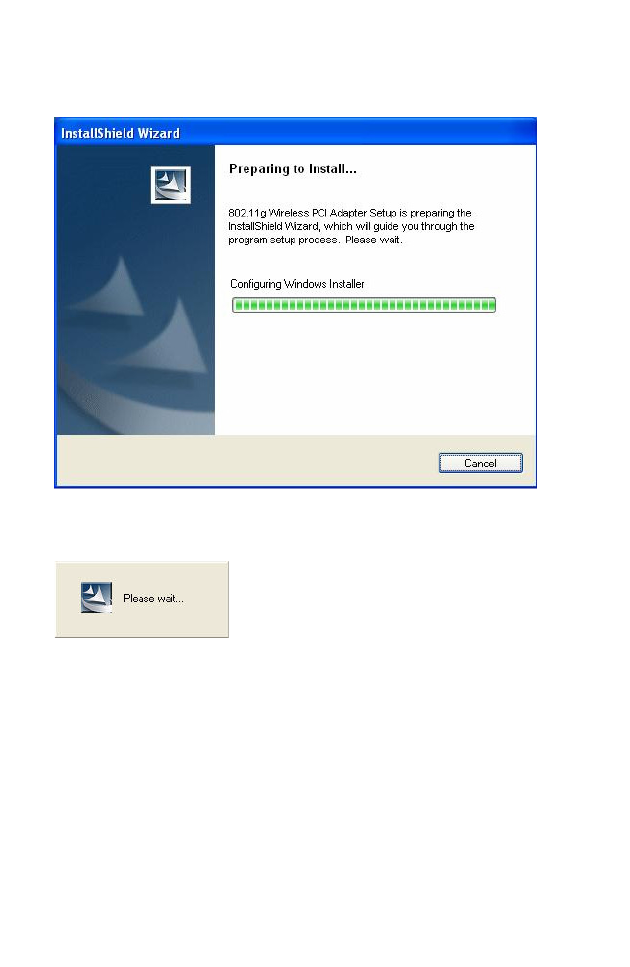
USING THE INSTALLATION WIZARD
9
2. Windows XP will automatically install the driver.
3. Then you will see the following message.
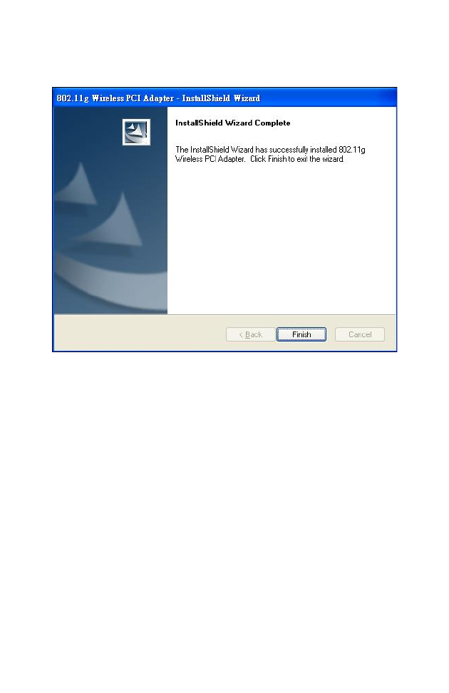
USING THE INSTALLATION WIZARD
10
4. Click Finish to exit the wizard.
5. The driver and utility installation is completed. Your adapter is
now ready for use.

11
UTILITY CONFIGURATION
Using the SMCWPCI-G2 Utility Program
Once the installation is complete, the configuration utility can be
accessed from the Start menu, or you can access it through the
quick launch icon on the desktop.
When the utility program is running, there will be a quick launch
icon in the lower right-hand corner of the task bar. If the icon is
GREEN, you have a good connection. If it shows RED, try to turn
the antenna in a different direction, or move closer to the access
point on your network. If the icon is still RED, then follow the
procedures described below, and verify that the SSID and radio
channel are configured to match the settings on the access point
to which you want to connect.
Double-clicking the quick launch icon will open the Wireless PCI
Adapter Utility, providing quick access to the adapter settings.
The configuration utility includes the following tabs:
Configuration – Allows you to set parameters for the adapter.
Link information – Shows the connection status.
IP information – Displays TCP/IP data.
Site Survey – Scans/Shows all wireless devices within the
adapter’s signal range.
Version information – Shows the driver and utility version
information.

USING THE SMCWPCI-G2 UTILITY PROGRAM
12
Radio On/Off – Click this button to turn on/turn off the wireless
radio signal of the adapter.
Help – Click this button to view the help file.
Close – Click this button to exit the utility.
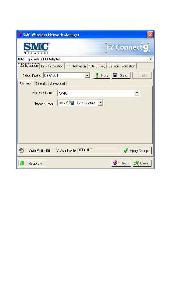
Configuration
When you start the Wireless PCI Adapter utility, the information
window for the SMCWPCI-G2 is shown as in the figure on the
following page.
Select Profile – To specify a profile for a specific configuration of
parameters.
New – Click this button to create a new profile.
Save – Click this button to save a profile after configuring the
settings.
Delete – Select the profile from the drop-down menu, and click
this button to delete the profile.
Auto Profile On/Off – Click this button to turn on/off the Auto
Profile feature.
Active Profile – The profile settings that you are using for the
current connection.
Click Apply Changes after you have made your selection.
USING THE SMCWPCI-G2 UTILITY PROGRAM
13
Common Tab
Network Name – This is the Service Set ID (SSID) for the
wireless network to which you want to connect.
Network Type – Set the station operation mode to Ad Hoc for
network configurations that do not have an access point, or to
Infrastructure for configurations with an access point.
USING THE SMCWPCI-G2 UTILITY PROGRAM
14
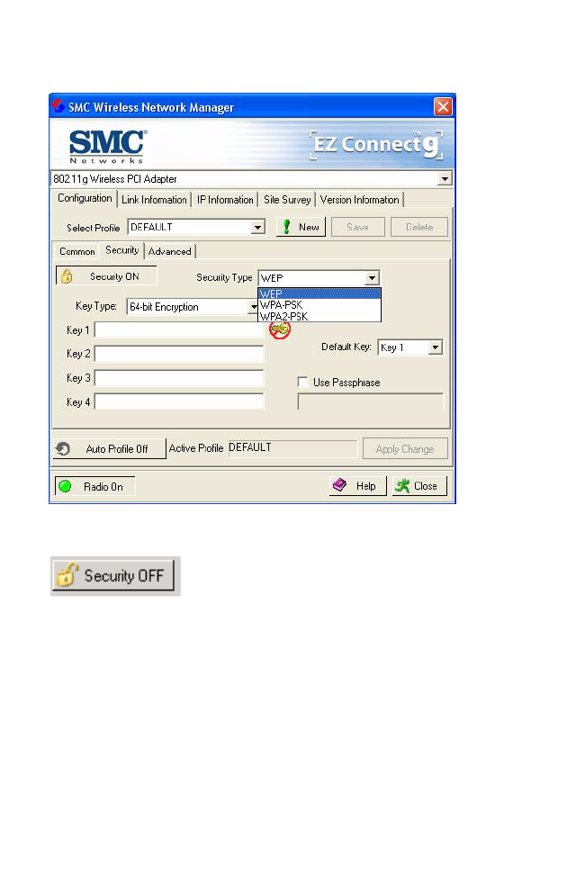
Security Tab
Go to the security tab to set the security features for your adapter.
Click on this security button to turn on/turn off
the security function.
Turn on the security function, and set detail parameters for your
adapter.
To prevent unauthorized access, this adapter supports WEP
(Wired Equivalent Privacy), and WPA/WPA2-PSK (Wi-Fi
Protected Access).

USING THE SMCWPCI-G2 UTILITY PROGRAM
15
WEP
WEP implemented in the SMCWPCI-G2 is based on the RC4
encryption algorithm. The security keys provided to ensure data
confidentiality are four 10-bit keys for the 64-bit WEP setting and
one 26-bit key for the 128-bit WEP setting. WEP security protects
your wireless LAN against eavesdropping and unauthorized
access by intruders.
Security Type – WEP (Wired Equivalent Privacy) and
WPA(2)-PSK (Wi-Fi Protected Access-Pre-Shared Key) are
implemented in the SMCWUSBS-N2 adapter to prevent
unauthorized access.
Key Type – Select 64-bit encryption, 64-bit encryption (ASCII),
128-bit encryption,or 128-bit encryption (ASCII).
Default Key – Choose one key, 1~4, for encryption.
Use Passphrase – Check this box to auto-generate keys for
encryption. First, check this box, then enter a string of characters
into the space. Encryption keys will be generated automatically.
When Key Type is set to 128-bit, only one key will be generated. If
Key Type is set to 64-bit, four keys will be generated. Note that
you must use the same passphrase and default key on all the
other clients in your network.
How to set up WEP:
If you are transmitting sensitive data across wireless channels,
you should enable Wired Equivalent Privacy (WEP) encryption.
WEP provides a basic level of security, preventing unauthorized
access to the network and encrypting data transmitted between
wireless clients and the access point. WEP uses static shared
keys (fixed-length hexadecimal or alphanumeric strings) that are
manually distributed to all clients that want to use the network.

USING THE SMCWPCI-G2 UTILITY PROGRAM
16
WEP is the security protocol initially specified in the IEEE 802.11
standard for wireless communications. For more robust wireless
security, the SMCWPCI-G2 provides Wi-Fi Protected Access
(WPA) for improved data encryption and user authentication.
Only one key is needed for WEP to function. However, the IEEE
802.11 standard specifies that there must be four keys for each
device. For security purposes, the key should be changed on a
regular basis. Multiple keys are supported to allow the user to
change keys with minimal disruption of the network.
To set up the WEP function, take the following steps:
Select 64-bit encryption, 64-bit encryption (ASCII), 128-bit
encryption,or 128-bit encryption (ASCII) in the Key Type field.
To automatically generate keys, check the Use Passphrase box,
and type in a string of characters in this field.
In the Default Key field, select one key as the default key that you
want to use for encryption.
Or
Select 64-bit encryption, 64-bit encryption (ASCII), 128-bit
encryption,or 128-bit encryption (ASCII) in the Key Type field.
In the Default Key field, select one key as the default key that you
want to use for encryption.
Manually type in a string of characters in the corresponding key
number field that you selected in step 2.
Click Apply Change to allow the settings to take effect.
USING THE SMCWPCI-G2 UTILITY PROGRAM
17
When setting up WEP without using the Use Passphrase
function, if the Key Type is set to Hex, only Hexadecimal
characters (range: 0~9 and A~F) can be used. When encryption
is set to 64-bit, a maximum of 10 Hex characters can be entered
in the Key field. When encryption is set to 128-bit, a maximum of
26 Hex characters can be used. If the Key Type is set to ASCII,
and encryption is set to 64-bit, then 5 ASCII characters can be
used in the Key field. For 128-bit encryption, 13 ASCII characters
can be used.
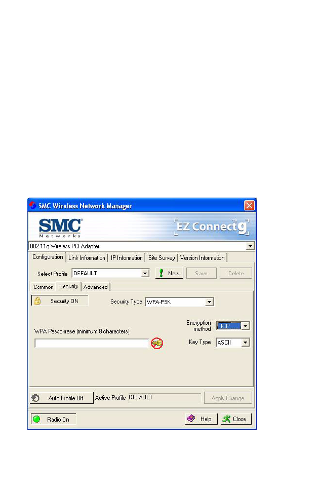
WPA-PSK/WPA2-PSK
How to set up WPA/WPA2-PSK:
Wi-Fi Protected Access is a standards-based, interoperable
security enhancement that strongly increases the level of data

USING THE SMCWPCI-G2 UTILITY PROGRAM
18
protection and access control for existing and future wireless LAN
systems. It will be forward-compatible with the upcoming
IEEE 802.11i standard. WPA employs a combination of several
technologies to provide an enhanced security solution for 802.11
wireless networks, including TKIP (Temporal Key Integrity
Protocol) for data protection and 802.1x for authenticated key
management. WPA provides a simple operating mode that uses
just a pre-shared password for network access. The Pre-Shared
Key mode uses a common password for user authentication that
is manually entered on the access point and all wireless clients
on the network.
To use the WPA function, take the following steps:
1. Select Security Type, WPA-PSK/WPA2-PSK from the
drop-down menu.
2. Type in the WPA Passphrase (Pre-Shared Key: PSK).
3. Choose Encryption method for data protection of the
WPA-PSK.
4. Select ASCII or Hex in the Key Type field
5. Click Apply Change to allow the settings to take effect.
Note: The WPA Passphrase character limit needs to be between
8-63 characters.
Manual Pre-Shared Key supports up to 64-Hex characters. If
there is no authentication server on your SOHO network, you can
issue the Pre-Shared Key to the adapter that is connected to the
access point. Be sure to use the same key for the wireless access
point and the connected adapter.
USING THE SMCWPCI-G2 UTILITY PROGRAM
19
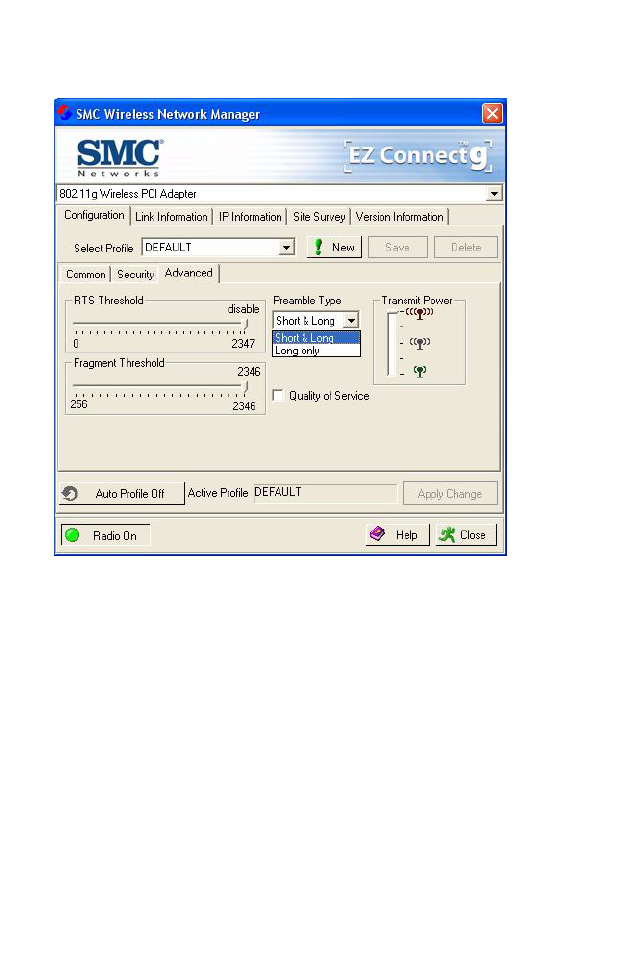
Advanced
RTS Threshold – This sets the packet size threshold at which a
Request to Send (RTS) signal must be sent to the receiving
station prior to the sending station starting communications.
Devices contending for the wireless medium may not be aware of
each other. The RTS mechanism can solve this problem. The
larger the threshold, the faster the speed.

USING THE SMCWPCI-G2 UTILITY PROGRAM
20
Fragment Threshold – Sets the minimum packet size that can
be transmitted from the adapter without being fragmented.
Fragmentation can increase the reliability of transmissions
because it increases the probability of a successful transmission
due to smaller frame size. The larger the threshold, the faster the
speed.
Preamble Type – The preamble is used to acquire the incoming
signal and synchronize the receiver. If all the clients in your
service area support the short preamble or can automatically set
the preamble type, then setting the preamble on the access point
to short can boost your throughput. (Options: Short & Long, Long
only, Short only; Default: Short & Long)
Quality of Service (QoS) – The QoS function allows you to
differentiate traffic types and provide high-priority forwarding
service for applications such as VoIP or gaming.
Transmit Power – Move the slider bar up and down to select an
appropriate transmission power. Lower power reduces
interference, higher power gives more range.
USING THE SMCWPCI-G2 UTILITY PROGRAM
21
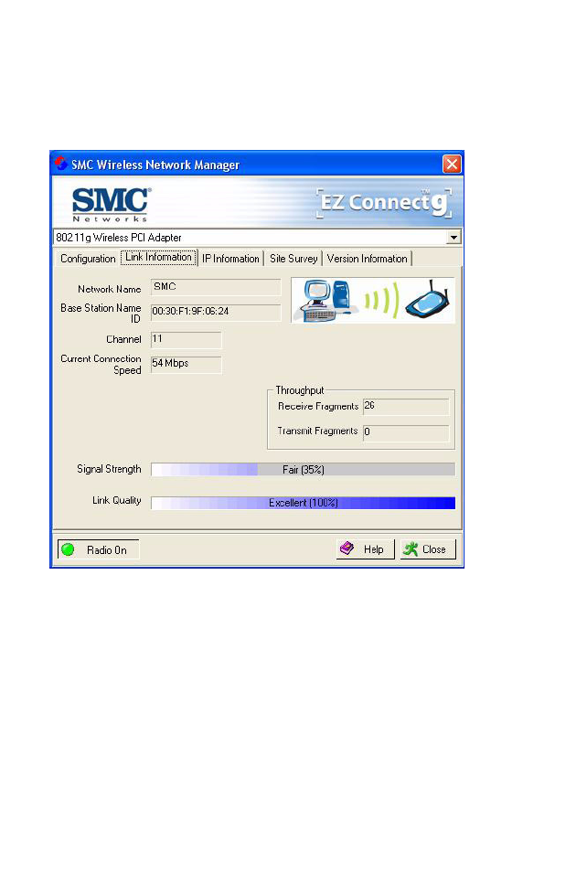
Link Information
The Link information screen displays information on the current
wireless network to which you are connected.
Network Name – This is the Service Set ID (SSID) for the
wireless network to which you want to connect.
Base Station Name ID – The MAC address of the access point
to which the card is connected in an Infrastructure network. In an
Ad Hoc network, this ID is a random number generated by the
first station that communicates with other stations in the network.
The BSS ID of the other stations will then be set to the same
value.

USING THE SMCWPCI-G2 UTILITY PROGRAM
22
Channel – This is the radio channel through which the access
point communicates to stations within the same network. A Basic
Service Set (BSS) consists of a group of wireless PCs and an
access point that is directly connected to the wired LAN. To
establish an Ad Hoc network, make sure the Channel is set to the
same radio channel as that used by the other wireless clients in
your group. However, if you are connecting to a network via an
access point, the adapter will automatically use the same channel
as that used by the access point.
The available channel settings are limited by local regulations that
determine the number of available channels.
Current Connection Speed – Shows the speed of the current
wireless connection.
Throughput – Shows the total number of data packets
transmitted and received.
Signal Strength – Shows the relative strength of the wireless
connection.
Link Quality – Shows the link quality of the wireless connection.
USING THE SMCWPCI-G2 UTILITY PROGRAM
23
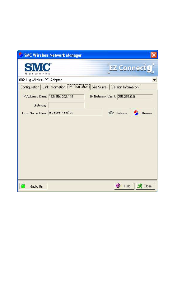
IP Information
The IP information screen displays TCP/IP information for the
adapter.
Now that you have configured your wireless adapter to connect to
the wireless network, your adapter needs to obtain new network
settings. By releasing old IP settings and renewing them with
settings from the access point, you will also verify that the adapter
is configured correctly.
IP Address Client – Internet address of your computer.
IP Netmask Client – A mask used to determine what subnet an
IP address belongs to.
USING THE SMCWPCI-G2 UTILITY PROGRAM
24
Gateway – The IP address of the network gateway.
Host Name Client – The computer’s name on the network.
Release – Click on this button to release the IP address.
Renew – Click on this button to get a new IP address.
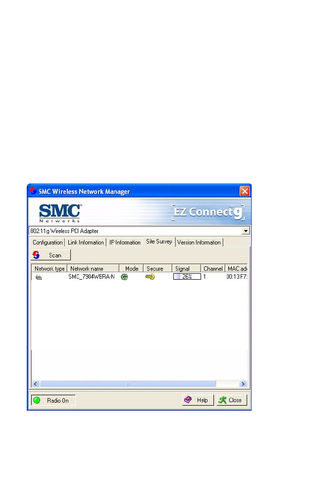
Site Survey
The Site Survey screen scans and displays available wireless
devices within range. Choose one of them to connect to by
double-clicking on an entry.
Network Type – Shows the network type. See “Configuration” on
page 12.
Network name – Service Set ID (SSID) on the network. See
“Configuration” on page 12.
USING THE SMCWPCI-G2 UTILITY PROGRAM
25
Mode – Shows the wireless connection mode, whether it’s
802.11b, 802.11g or 802.11n.
Secure - This shows security mechnism has been enabled. A key
icon indicates the encryption function is enabled.
Signal - This shows the signal strength of the listed wireless
devices.
Channel - This is the channel used for the wireless connection.
MAC address - This is the MAC address of the listed wireless
devices.
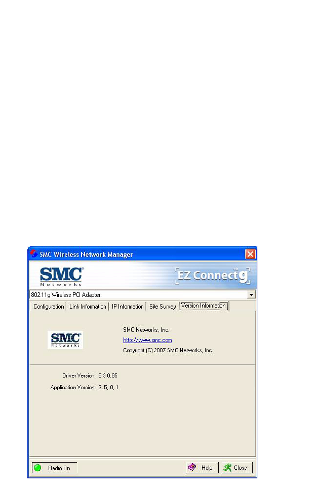
Version Information
The following screen shows the current version information of the
driver and configuration utility.
26
NETWORK CONFIGURATION
AND PLANNING
SMC’s EZ Connect Wireless Solution supports a stand-alone
wireless network configuration, as well as an integrated
configuration with 10/100 Mbps Ethernet LANs.
The SMCWPCI-G2 can be configured as:
•Ad hoc - for small groups that only communicate with each
other
•Infrastructure - for mixed wired/wireless LANs
Network Topologies
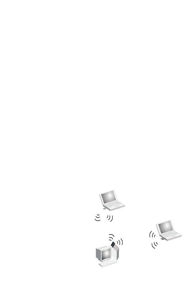
Ad Hoc Wireless LAN
An Ad Hoc wireless LAN
consists of a group of
computers, each equipped
with a wireless adapter,
connected via radio
signals as an independent
wireless LAN. Computers
in a specific Ad Hoc
wireless LAN must be
configured to the same
radio channel. An Ad Hoc
wireless LAN can be used
in a SOHO or temporary
environment.
Notebook with
Wireless USB Adapter
Notebook with
Wireless PC Card
PC with Wireless
PCI Adapter
Ad Hoc Wireless LAN
NETWORK TOPOLOGIES
27
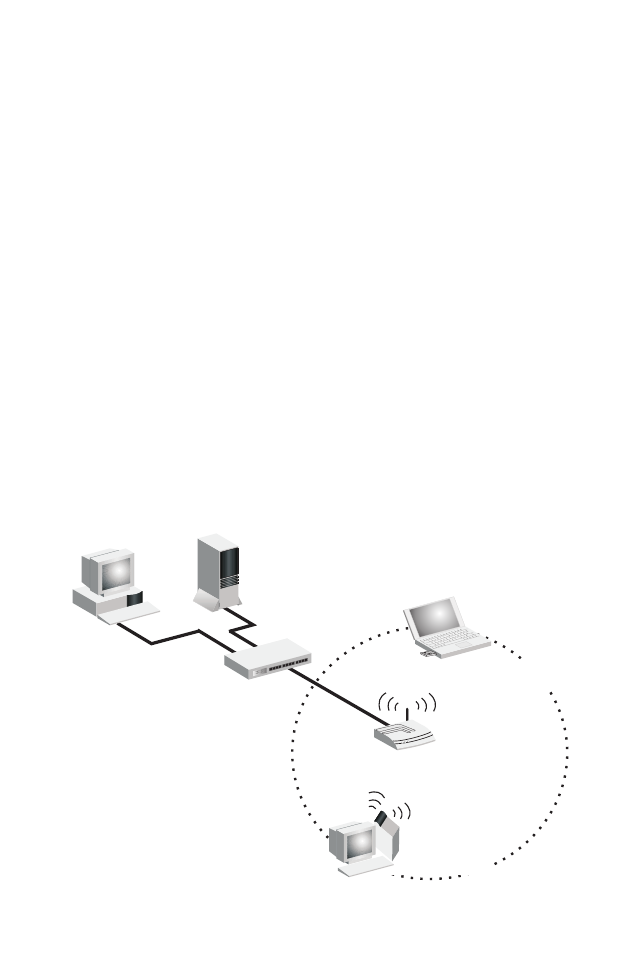
Infrastructure Wireless LAN
The SMCWPCI-G2 also provides wireless workstations with
access to a wired LAN. An integrated wired and wireless LAN is
called an Infrastructure configuration. A Basic Service Set (BSS)
consists of a group of wireless PC users and an access point that
is directly connected to the wired LAN. Each wireless PC in this
BSS can talk to any computer in its wireless group via a radio link,
or access other computers or network resources in the wired LAN
Infrastructure via the access point.
The Infrastructure configuration not only extends the accessibility
of wireless PCs to the wired LAN, but also extends the effective
wireless transmission range for wireless PCs by passing their
signal through one or more access points.
A wireless Infrastructure can be used for access to a central
database, or for connection between mobile workers, as shown in
the following figure.
File
Server
Switch
Desktop PC
Access Point
Wired LAN Extension
to Wireless Adapters
Notebook with Wireless
USB/PC Card Adapter
PC with Wireless
USB/PCI Adapter
SETTING THE COMMUNICATION DOMAIN
28
Setting the Communication Domain
Stationary Wireless PCs
The Basic Service Set (BSS) is the communication domain for
each access point. For wireless PCs that do not need to support
roaming, set the Service Set Identifier (SSID) for the wireless
card to the SSID of the access point to which you want to
connect. Check with your network administrator for the SSID.
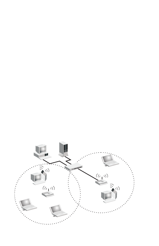
Roaming Wireless PCs
A wireless Infrastructure can also support roaming for mobile
workers. More than one access point can be configured to create
an Extended Service Set (ESS). By placing the access points so
that a continuous coverage area is created, wireless users within
this ESS can roam freely. All wireless adapters and access points
within a specific ESS must be configured with the same SSID and
to the same radio channel.
File
Server
Switch
Desktop PC
Access Point
Notebooks with Wireless
PC Card Adapters
Seamless Roaming
<BSS2>
<ESS>
<BSS1>
Notebook with Wireless
PC Card Adapter
Access Point
Wireless Cell
Coverage Area
PC with Wireless
PCI Adapter
PC with Wireless
PCI Adapter

SETTING THE COMMUNICATION DOMAIN
29
Before setting up an ESS for roaming, you need to choose a clear
radio channel and a suitable location for the access points to
maximize performance. (Refer to “Troubleshooting” on the
following page for detailed information.)

30
TROUBLESHOOTING
Check the following troubleshooting items before contacting SMC
Technical Support.
Adapter Installation Problems
If your computer cannot find the Wireless PCI Adapter, or the
network driver does not install correctly, check the following:
•Make sure the adapter is securely seated in the PCI slot.
Check for any hardware problems, such as physical damage
to the card’s connector.
•Try the card in another PCI slot. If this also fails, test your
computer with another PCI adapter that is known to operate
correctly.
•Make sure your computer is using the latest BIOS.
•If there are other network adapters in the computer, they may
be causing conflicts. Remove other adapters from the
computer and test the wireless adapter separately.
•Check for a defective computer or PC connection by trying the
adapter in another computer that is known to operate
correctly.

NETWORK CONNECTION PROBLEMS
31
Network Connection Problems
If the Link LED on the SMCWPCI-G2 does not light, or if you
cannot access network resources from the computer, check the
following:
•Make sure the correct software driver is installed for your
operating system. If necessary, try reinstalling the driver.
•Make sure the computer and other network devices are
receiving power.
•The access point you want to attach to may be defective. Try
using another access point.
•If you cannot access a Windows service on the network,
check that you have enabled and configured the service
correctly. If you cannot connect to a particular server, be sure
that you have access rights and a valid ID and password.
•If you cannot access the Internet, be sure you have configured
your system for TCP/IP.
If your wireless station cannot communicate with a computer in
the Ethernet LAN when configured for Infrastructure mode, check
the following:
•Make sure the access point that the station is associated with
is powered on.
•If you still cannot connect, change the access point and all the
stations within the BSS to another radio channel.
•Make sure the SSID is the same as that used by the BSS
configured on the access point, or the same as that used by
the access points in the extended service set (ESS).

NETWORK CONNECTION PROBLEMS
32
SMCWPCI-G2 Maximum Distance Table
Important Notice
Maximum distances posted below are actual tested distance
thresholds. However, there are many variables such as barrier
composition and construction, as well as local environmental
interference that may impact your actual distances and cause you
to experience distance thresholds far lower than those posted
below. If you have any questions or comments regarding the
features or performance of this product, or if you would like
information regarding our full line of wireless products, visit us at
www.smc.com, or call us toll-free at 800.SMC.4YOU. SMC
Networks stands behind every product sold with a 30-day
satisfaction guarantee and a limited-lifetime warranty.
SMCWPCI-G2 Wireless PCI Card Maximum Distance Table
Environmental
Condition
Speed and Distance Ranges
11Mbps 5.5 Mbps 2 Mbps 1 Mbps
Outdoors:
A line-of-sight environment
with no interference or
obstruction between the
access point and users.
160 m
(528ft)
195 m
(640 ft)
255 m
(837 ft)
350 m
(1155 ft)
Indoors:
A typical office or home
environment with floor to
ceiling obstructions between
the access point and users.
72 m
(236 ft)
73 m
(240 ft)
73 m
(240 ft)
75 m
(246 ft)

NETWORK CONNECTION PROBLEMS
33
SMCWPCI-G2 Wireless PCI Card Maximum Distance Table
Environmental
Condition
Speed and Distance Ranges
54
Mbps
48
Mbps
36
Mbps
24
Mbps
18
Mbps
12
Mbps
6-9
Mbps
Outdoors:
A line-of-sight
environment with
no interference or
obstruction
between the
access point and
users.
60 m
(197 ft)
90 m
(295 ft)
150
(492 ft)
190
(623 ft)
220
(722 ft)
270
(886 ft)
350
(1155 ft)
Indoors:
A typical office or
home
environment with
floor to ceiling
obstructions
between the
access point and
users.
40
(131 ft)
50
(164 ft)
60
(197 ft)
65
(213 ft)
70
(230 ft)
110
(361 ft)
180
(591 ft)

34
SPECIFICATIONS
Below is an outline of the technical specifications for the
SMCWPCI-G2.
Functional Criteria
Data Rate: Up to 54 Mbps
Operating Range: Indoor: up to 40 m (131 ft) at 54 Mbps
up to 75 m (246 ft) at 1 Mbps
Outdoor: up to 60 m (197 ft) at 54 Mbps
up to 350 m (1155 ft) at 1 Mbps
Radio Signal
Modulation: Orthogonal Frequency Division
Multiplexing (OFDM)
Complementary Code Keying (CCK)
Operating Frequency: USA (FCC): 2412~2462 MHz
Canada (IC): 2412~2462 MHz
Europe (ETSI): 2412~2472 MHz
Operating Channel: USA, Canada: 11 channels
ETSI: 13 channels
Sensitivity: -80 dBm (typical) for 802.11b
-65 dBm (typical) for 802.11g

SPECIFICATIONS
35
Physical Characteristics
Power Consumption: TX: 570 mA Max, RX: 350 mA Max
Dimensions: 120 x 62 mm (4.72 x 2.44 in)
LED Indicator: Power/Link, Activity
Host Interface: PCI Spec v. 2.2
Antenna
Antenna type: External detachable
Frequency Band: 2.4~2.5 GHz
Impedance: 50 Ohms Nominal
Gain: 2.0 dBi Peak
Radiation: Omni directional
Polarization: Vertical
VSWR (Voltage Standing
Wave Ratio): <= 2.0
Connector: Reverse SMA (SubMiniature version A)
Temperature Operating: -20 to 65 °C (-4 to 149 °F)
Storage: -30 to 75 °C (-22 to 167 °F)
Standards Conformance
Wireless Standard: IEEE 802.11b and IEEE 802.11g
Media Access Protocol: CSMA/CA with ACK
Environmental
Temperature: Operating: 0 to 50 °C (32 to 122 °F)
Storage: 0 to 70 °C (32 to 158 °F)
Humidity: 5 to 90% (non-condensing)
Vibration/Shock/Drop: IEC 68-2-34, IEC 68-2-27, IEC68-2-32

SPECIFICATIONS
36
Certification
Standards: Meets FCC, R&TTE Directive
Software Drivers
NDIS Drivers: Windows 98 SE
Windows Me
Windows 2000
Windows XP
SMCWBR11-G
SMCWPCI-G2