Arcwave AX1255 ArcXTEND Wireless Hub Access Point User Manual 41FF9EC4 410D 10B8EE
Arcwave, Inc. ArcXTEND Wireless Hub Access Point 41FF9EC4 410D 10B8EE
Arcwave >
Users Manual

Copyright 2005 Arcwave, Inc.
ARCXtend Wireless Plant Extension
Solution
5.8 GHz / 5.3 GHz Operation
User Manual
R1.4 Issue 4
P/N: 920-20003-010
© 2001-2004 Arcwave, Inc.
910 Campisi Way, Suite 1C,
Campbell, CA 95008 USA,
Phone: 408-558-2300
www.arcwaveinc.com

ARCXTEND USER MANUAL – R1.4, ISSUE 4
Copyright 2005 Arcwave, Inc. ii
REVISION HISTORY
ISSUE # AUTHOR CHECK OUT CHECK IN COMMENTS
0.5 CM 09/21/2004 R1.4 DRAFT - DOCUMENT IN PROCESS
1.3 CM 10/25/04 12/07/04 R.14 ISSUE 1.3 – INCORPORATED EDITS
4 CM 12/22/04 01/07/05 R1.4 ISSUE 4
UPDATED HUB POWER CONSUMPTION SPECIFICATION
UPDATE DS RANGE SPECIFICATIONS
CHANGED POWER INSERTER DIAGRAM,
UPDATED HUB TX POWER AND GAIN VALUES
REMOVED INDUSTRY CANDA CERTIFICATION
CHANGED FCC CERTIFICATION FROM CLASS B TO
CLASS A
ADDED NOTE THAT HIGH POWER TRANMIST MODE IS
FOR USE WITH AX1255-VM-90 AND AX1255-SM-90 HUBS
ADDED NOTE THAT THE DOWNSTREAM POWER LEVEL
INTO THE CABLE MODEM WITH 256 QAM OPERATION IS -
6 TO +15 DBMV.
ADDED MAXIMUM DISTANCE OF 300 FEET FROM CPE TO
18 VDC POWER PACK
UPDATED DEFAULT UPSTREAM BAND SETTING TABLE
ADDED PART 15, SECTION 15.21 USERS WARINING.
ARCXTEND USER MANUAL – R1.4, ISSUE 4
Copyright 2005 Arcwave, Inc. iii
NOTICES
The information in this publication is subject to change without notice. Arcwave shall not be liable
for technical or editorial errors or omissions nor for any damages resulting from the use of this
material.
Each configuration tested or described may or may not be the only available solution. This test is
not a determination of product quality or correctness, nor does it ensure compliance with any
federal, state or local requirements. Arcwave does not warrant products other than its own strictly
as stated in Arcwave’s product warranties.
U.S. Federal Communication Commission (FCC) Notification
This device complies with part 15 of the U. S. FCC Rules and Regulations and with is subject to
the following two conditions: (1) This device may not cause harmful interference, and (2) This
device must accept any interference received, including interference that may cause undesired
operation. In Canada, users should be cautioned to take note that high power radars are
allocated as primary users (meaning they have priority) of 5250 – 5350 MHz and 5650 – 5850
MHz and these radars could cause interference and/or damage to license-exempt local area
networks (LELAN).
This equipment has been tested and found to comply with the limits for a Class A digital device,
pursuant to Part 15 of the U.S. FCC Rules. These limits are designed to provide reasonable
protection against harmful interference in a residential installation. This equipment generates,
uses, and can radiate radio-frequency energy and, if not installed and used in accordance with
these instructions, may cause harmful interference to radio communications. If this equipment
does cause harmful interference to radio or television reception, which can be determined by
turning the equipment on and off, the user is encouraged to correct the interference by one or
more of the following measures:
Increase the separation between the affected equipment and the unit;
Connect the affected equipment to a power outlet on a different circuit from that which the
receiver is connected to;
Consult the dealer and/or experienced radio/TV technician for help.
WARNING (Part 15, Section 15.21)
Changes or modifications not expressly approved by Arcwave, Inc. could void the user's
authority to operate the equipment.
FCC IDs Numbers are listed below:
FCC Identifier: PLRAX1255
FCC Identifier: PLRAX3155

ARCXTEND USER MANUAL – R1.4, ISSUE 4
Copyright 2005 Arcwave, Inc. iv
RF Exposure
CAUTION: To ensure compliance with FCC RF exposure requirements, the antenna used for
this device must be installed to provide a separation distance of at least 20 cm from all persons
and must not be located or operated in conjunction with any other antenna or radio transmitter.
Arcwave and the Stylized Arcwave Logo, ARCXtend, ARCSmart, and PureBurst are trademarks
of Arcwave, Inc. All other product or service names are the property of their respective owners.
© Arcwave, Inc. 2004. Arcwave, Inc. 910 Campisi Way, Campbell, Ca, 95008
http://www.arcwaveinc.com
ARCXTEND USER MANUAL – R1.4, ISSUE 4
Copyright 2005 Arcwave, Inc. v
TABLE OF CONTENTS
INTRODUCTION 1
About this Document 1
Purpose 1
Audience 1
Prerequisites 1
Feedback 1
PRODUCT DESCRIPTION 2
Overview 2
System Configuration 2
Cable and Wireless Network Interfaces 3
Frequency Mapping 3
Signal Levels 3
Element Management 4
Applications 4
ARCXtend Wireless Drop 4
Wireless Feeder 5
Wireless Overlay and Upstream 5
Equipment Description 6
ARCXtend Network Hub 6
Hub Interfaces 6
Hub Configurations 7
Hub Mounting Kits 8
ARCXtend CPE 9
CPE Configuration and Accessories 10
Downstream Signal Attenuators 11
ARCSmartTM 2.0 Intelligent Network Management 11
DOCSIS 2.0 Compliant ECM 11
Watchdog Timer 11
SNMP-compliant Arcwave Enterprise MIB 11
HTTP-based user interface 12
ARCSmart firmware upgrade 12
Advanced Network Management Features 13
Plug-n-Play 13
Downstream frequency agility 13
Settable Hub Transmit Power 13
PureBurst Ingress Noise Suppression 13
PRE-DEPLOYMENT PLANNING 15
Hub Site Selection 15
Line of Site 15
Range 15
Equipment Location 16
Checking for Interference 17
CPE Site Selection 17
Height and Location 17
Checking for Interference 18
Channel Plan 19
Downstream Configuration 19
Downstream Block Diagram 19
Upstream Configuration 20
Upstream Block Diagram 20
ARCXtend Multiple Hub Configurations 21
IP Network Preparation 21
ARCXTEND USER MANUAL – R1.4, ISSUE 4
Copyright 2005 Arcwave, Inc. vi
Hub’s Default IP Address 21
Cable Network IP Address 21
ECM Configuration File 22
TCP/IP Port Filtering 22
Hub Electrical Interface 22
AC Powering and Surge Protection 22
DC Powering 23
RF Signal Power Level and Quality 23
CPE Electrical Interface 23
AC Powering and Surge Protection 23
Lightning Protection 23
INSTALLATION AND COMMISSIONING 24
Prerequisites 24
Link Budget 24
Personnel 24
Equipment and Materials 24
Equipment Ordering and Staging 25
Hub installation & commissioning 26
Setup the Hub Power and RF Connection 26
Secure the Hub to the Strand 26
(Optional) Secure the Hub to the Mast 27
Establish a Local Connection to the Hub 27
Verify the Embedded Cable Modem has achieved operational maintenance state. 28
Set up and verify the Hub’s cable plant interface 28
Set up and verify the Hub’s wireless interface 28
Set the Hub Management Mode 29
CPE installation 29
Affix the CPE mounting mast 29
Install the Coaxial Cable and Ground Connection 30
Install the power adaptor and DC inserter 32
CPE Alignment 32
Connect the signal strength meter 32
Verify CPE output signal at input to cable modem 33
Cable Modem Installation 34
If the cable modem registers with the network 34
If the cable modem doesn’t register with the network 35
Link Verification 37
Downstream path measurements 37
Upstream path measurements 37
USER INTERFACE 39
Accessing the Interface 39
Cable Status Page 39
System Info Page 41
General Information 41
Cable Modem IP Information 42
Attached Device 42
Signal Page 43
Arcwave MIB 43
Upstream Signal 44
DOCSIS 1.0 Class of Service Parameters 44
Event Log Page 44
System Event Log 45
Maintenance 47
Arcwave MIB page 48
Arcwave MIB Maintenance 48
ARCXTEND USER MANUAL – R1.4, ISSUE 4
Copyright 2005 Arcwave, Inc. vii
Firmware Download Information 51
Arcwave MIB Real Time Monitor Information 51
ACCESSORIES 53
ARCXtend Accessories 53
SPECIFICATIONS 54
AX1255 Network Hub 54
AX3155 Customer Premise Antenna / Transceiver (CPE) 55
Environment Specifications 5756
CUSTOMER SUPPORT 5857
Service Policy 5857
Services 5857
Standard Service Agreements 5958
Technical Services 5958
Technical Assistance 5958
Return of Material Authorization (RMA) Initiation and Tracking 5958
Onsite Support 5958
Emergency Onsite Support 6058
Software / Firmware Services 6059
Updates 6059
Upgrades 6059
Hardware Services 6059
Warranty Repair and Return 6059
Out of Warranty Repair and Return 6160
Spares 6160
Training Services 6160
Summary of Services 6160
ARCWAVE ENTERPRISE MIB 6463
Arcwave MIB Structure 6463
Arcwave MIB Element Definitions 6564
Arcwave Alarm Descriptions 7069
Arcwave Traps 7170
Sample Trap Format 7170
arcwaveEIAInputchannel VALUES 7372
CABLE MODEM INITIALIZATION 7473
ARCXTEND USER MANUAL – R1.4, ISSUE 4
Copyright 2005 Arcwave, Inc. viii
FIGURES
Figure 2-1: ARCXtend Solution Architecture.................................................................................2
Figure 2-2: ARCXtend Solution Elements.....................................................................................3
Figure 2-3: Wireless Drop.............................................................................................................4
Figure 2-4: Wireless Feeder.........................................................................................................5
Figure 2-5 AX1255-SM (on left) and AX1255-VM Connectors (on right).......................................6
Figure 2-6: CPE RF Connector ..................................................................................................10
Figure 3-1: Fresnel Zone Clearance Requirement......................................................................15
Figure 3-2: CPE Site Survey Setup ............................................................................................18
Figure 3-3: ARCXtend Downstream Block Diagram ..................................................................19
Figure 3-4: ARCXtend Upstream Block Diagram.......................................................................20
Figure 4-1: Hub Installation Diagram..........................................................................................26
Figure 4-2: Mast Mount Kit Bracket Offset..................................................................................27
Figure 4-3: CPE Mounting Diagram...........................................................................................30
Figure 4-4: CPE Wiring Diagram ...............................................................................................30
Figure 4-5: Grounding device at subscriber premises.................................................................31
Figure 4-6: Power Inserter and AC/DC adaptor..........................................................................32
Figure 4-7: AR100 Signal Strength Meter (SSM)........................................................................33
Figure 5-1: Hub login screen ......................................................................................................39
Figure 5-2: Cable Status page....................................................................................................39
Figure 5-3: System Info page .....................................................................................................41
Figure 5-4: Signal Page..............................................................................................................43
Figure 5-6: Maintenance Page ...................................................................................................47
Figure 6-1: AR100 Signal Strength Meter...................................................................................53

ARCXTEND USER MANUAL – R1.4, ISSUE 4
Copyright 2005 Arcwave, Inc. ix
TABLES
Table 2-1: Table for 10/100 Mbits Ethernet wiring and Power over Ethernet ................................7
Table 2-2: Hub Configurations......................................................................................................7
Table 2-3 Hub Mounting Options..................................................................................................9
Table 2-4: CPE Models ..............................................................................................................10
Table 2-5 SNMP Community String (Private), Read-Write Access .............................................12
Table 2-6 SNMP Community String (Public), Read-Write Access...............................................12
Table 3-1: AX1255-SM-90 Strand Mounted Network Hub (18 ft off the ground) .........................16
Table 3-2: AX1255-SM-25 Strand Mounted Network Hub (18 ft off the ground) .........................16
Table 3-3: AX1255-VM-90 Vertical Mounted Network Hub (100 ft off the ground)......................16
Table 3-4: Downstream Hub to CPE Channel Mapping..............................................................18
Table 4-1: Installation Equipment & Materials.............................................................................25
Table 4-2: DS received power level troubleshooting...................................................................34
Table 4-3: US transmit power level troubleshooting....................................................................35
Table 4-4: Cable modem registration .........................................................................................36
Table 4-5: Downstream path measurements..............................................................................37
Table 4-6: Upstream Path Measurements..................................................................................38
Table 5-1: ARCSmart Event Messages......................................................................................47
Table 5-2: Default Upstream Band Setting .................................................................................52
Table 7-1: AX1255 Specifications...............................................................................................55
Table 7-2: AX3155 Specifications...............................................................................................56
Table 7-3 Environmental Specifications..................................................................................5857
Table 8-1: Arcwave Service Offering Matrix ...............................................................................63
Table A-1 Arcwave MIB Definitions and OID ..............................................................................69
Table A-2 Arcwave Alarm Definitions .........................................................................................70
Table A-3 Arcwave Traps...........................................................................................................71
Table A-4 arcwaveEIAInputchannel Values................................................................................73
Table B-1 Cable Modem Initialization Steps...............................................................................75

ARCXTEND USER MANUAL – R1.4, ISSUE 4
Copyright 2005 Arcwave, Inc. 1
INTRODUCTION
About this Document
Purpose
Proper installation and verification are critical elements to achieving optimal wireless performance.
This document provides cable plant installation professionals with information needed for
successfully deploying and maintaining Arcwave’s ARCXtend Wireless Plant Extension Solution.
Action items in this document preceded with by the )symbol.
Audience
This document is designed to be used by cable plant installation professionals. It can be performed
by one person with the proper training, wireless link planning, and tools. It is recommended,
however, that two people be present during the alignment process between the ARCXtend Network
Hub (Hub) and ARCXtend CPE (CPE): one person located at the Hub and the other at the CPE.
Prerequisites
Professionals using this process should be trained and familiar with installation and troubleshooting
of cable drops, cable modems, and ARCXtend.
Feedback
We welcome your feedback on Arcwave documentation. This includes feedback on structure,
content, accuracy, or completeness of our documents, and any other comments have. Please send
your comments to marketing@arcwaveinc.com.
ARCXTEND USER MANUAL – R1.4, ISSUE 4
Copyright 2005 Arcwave, Inc. 2
PRODUCT DESCRIPTION
Overview
The ARCXtend solution is a wireless point-to-multipoint plant extension solution supporting the
wireless transmission of digitally modulated RF signals between a cable system operator’s coaxial
cable plant and one or more customer sites. The solution consists of a Strand or Vertically Mounted
Network Hub (Hub) and one or more Customer Premise Equipments (CPE). The Hub connects
directly to the coaxial portion of cable plant using a standard power passing, passive tap or coupler
and is line powered over coax using 60-90 VAC. The CPE is installed at the customer site,
connects to a standard cable modem, and is powered locally using an AC power pack.
Coax Line - Two Way
Downstream to other Nodes
Power
Passing
Tap
Wireless Upstream
5250 - 5350 MHz
(14 channels)
ARCXtend
AX1255-SM
Network Hub
Wireless Downstream
5725 - 5850 MHz
(20 channels)
Off-Air
TV Stations
Satellite-Fed
Services
Cable Modem
System (CMTS)
C
o
m
b
I
n
e
r
DOCSIS
Downstream 90
to 860 MHz
DOCSIS
Upstream 5 to
to 45 MHz
Cable Modem
ARCXtend
AX3155 CPE
Splitter Coax
DS 425 to 550 MHZ US 5 to 45 MHz
Figure 2-1: ARCXtend Solution Architecture
System Configuration
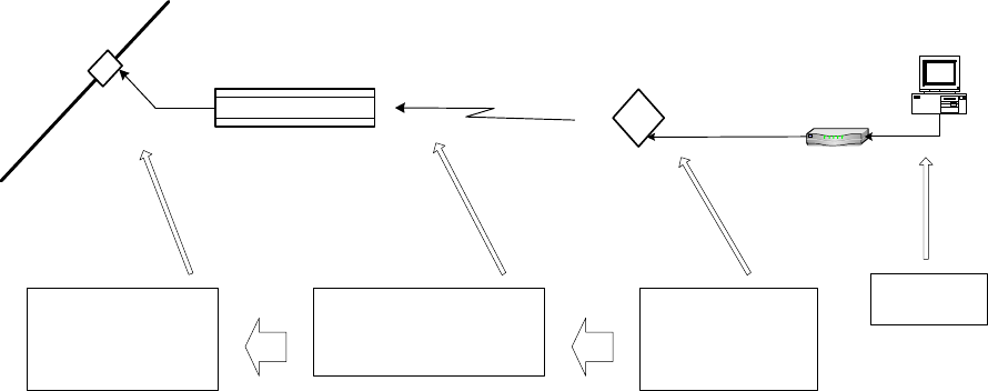
Figure 2-2 details the elements of the ARCXtend solution provided by Arcwave (shaded) and
provided by the cable operator:
ARCXTEND USER MANUAL – R1.4, ISSUE 4
Copyright 2005 Arcwave, Inc. 3
RJ-45
F Type-2
F Type-1
CPE
Mounting
Kit
Cable Plant
60-90VAC and
DOCSIS Signal
AC Power Pack
DC Inserter LP Attenuator
Hub Mounting
Kit
Hub
PC
POE
-20 dB Monitor
Port CPE Cable Modem
Provided by
Arcwave
RJ-45
F Type-2
F Type-1
CPE
Mounting
Kit
Cable Plant
60-90VAC and
DOCSIS Signal
AC Power Pack
DC Inserter LP Attenuator
Hub Mounting
Kit
Hub
PC
POE
-20 dB Monitor
Port CPE Cable Modem
Provided by
Arcwave
Figure 2-2: ARCXtend Solution Elements
Cable and Wireless Network Interfaces
Frequency Mapping
The Hub receives a digitally modulated RF signal in the range between 90 and 860 MHZ to and
upconverts it to a selected wireless carrier frequency in the 5,725 to 5,850 MHz license-free band.
The channel can be 64 QAM or 256 QAM and up to 6 MHz wide.
The CPE receives the wireless signal and downconverts it to an RF channel in the range 425 to 550
MHz (the specific value is wireless carrier frequency minus 5300 MHz) which is provided to a Cable
Modem.
The CPE receives a digitally modulated RF signal in the range between 5 to 42 MHz and
upconverts it to a pair of fixed frequencies (one high computed as 5,300 MHz plus the RF signal
frequency, one low computed as 5,300 minus the RF signal frequency) in the range 5,250 to 5,350
MHz.
The Hub receives the wireless signal and downconverts it to the appropriate RF channel in the
range 5 to 42 MHz.
Signal Levels
The Hub includes Automatic Gain Control (AGC) on the RF input and can accept an RF input signal
of -5 to +25 dBmV while providing optimum wireless transmit power. The hub wireless transmitter
power, determined by the Downstream Path Optimization setting, can be set for on of three
modes: High (+19 dBm), Medium (+13 dBm), or Low (+3 dBm).
Note: The “High” power setting is for use with the AX1255-SM-90 and AX1255-VM-90 Network
Hubs. Use of the “High” power setting with the AX1255-SM-25 cancels the FCC certification and
voids the user’s authority to operate the unit in the 5.8 GHz band.
ARCXTEND USER MANUAL – R1.4, ISSUE 4
Copyright 2005 Arcwave, Inc. 4
The upstream output power out of the Hub into the cable plant is controlled by the Upstream
Attenuation parameter. This parameter is automatically set by the Hub based on the transmit
power setting of the Embedded Cable Modem (ECM) contained in the Hub.
The gain of the CPE is fixed in both the upstream and downstream direction. The transmit power of
the CPE directed towards the Hub will vary based on the input RF signal received from the cable
modem. The CPE can accept an input RF signal between 20 and +58 dBmV from a cable modem.
The downstream output power out of the CPE directed towards the cable modem will vary based on
the distance between the Hub and the CPE. It is typically in the range of +10 to +30 dBmV.
Arcwave provides specially designed low pass attenuators to reduce the downstream power level to
within the – 15 dBmV and +15 dBmV operating range of a cable modem. Note that for 256 QAM
operation that the downstream power level into the cable modem must be at least -6 dBmV.
Element Management
Each Hub contains Arcwave’s ARCSmart intelligent network management which combines an
embedded DOCSIS 2.0 compliant cable modem, SNMP-compliant Arcwave Enterprise MIB
(management information base) and a processing engine with upgradeable software to support low
cost configuration monitoring, and troubleshooting of a Hub.
Management of the CPE can be most cost effectively achieved using the capabilities built into the
subscriber cable modem. The CPE has no settable parameters so management is not required.
Applications
ARCXtend Wireless Drop
Figure 2-3: Wireless Drop
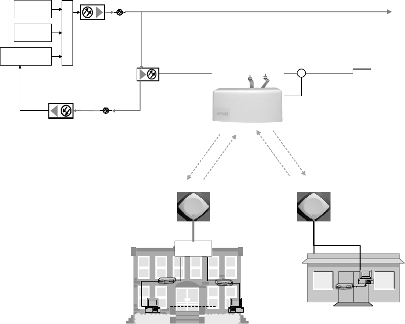
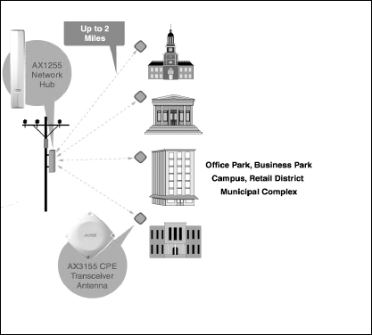
ARCXtend can be deployed as a wireless drop connecting customers located across a parking lot,
highway, or river or in areas with zoning restrictions to your plant. An AX1455-SM strand mount hub
mounts directly on your plant:
ARCXTEND USER MANUAL – R1.4, ISSUE 4
Copyright 2005 Arcwave, Inc. 5
• The AX1255-SM-90 hub includes a 90° beamwidth antenna with a range up to 1 mile at 64
QAM and ¼ mile at 256 QAM;
• The AX1255-SM-25 includes a 20° beamwidth antenna with a range of 2 miles at 64 QAM
and 1 mile at 256 QAM.
Wireless Feeder
Figure 2-4: Wireless Feeder
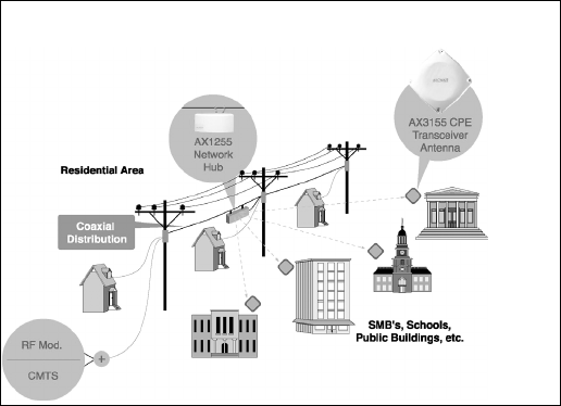
ARCXtend can be deployed as a wireless feeder solution connecting hundreds of customers. An
AX1255-VM vertical mount hub mounts on a utility pole, tower, or building providing the extended
range coverage required for retail districts, office parks, or campuses.
• The AX1255-VM-90 vertical mount hub includes a 90° beamwidth antenna with a range of 2
mile at 64 QAM and ½ mile at 256 QAM.
Wireless Overlay and Upstream
The ARCXtend Wireless overlay solution delivers additional DOCSIS capacity without costly
network upgrades or deployments. It is an ideal solution for providing DOCSIS-based services to
isolated communities or out-of-franchise markets. A typical ARCXtend cell site, mounted on 100
foot tower, can cover over 100 square miles and could provide commercial-grade high speed data
service for up to 1,600 customers.
The ARCXtend Wireless upstream solution provides a quick and cost effective means for upgrading
older one-way plants to deliver 2-way DOCSIS service. With the ARCXtend wireless upstream
solution, two-way service can be up and running in weeks rather than months at a fraction of the
cost of upgrading the entire plant.
ARCXTEND USER MANUAL – R1.4, ISSUE 4
Copyright 2005 Arcwave, Inc. 6
Equipment Description
ARCXtend Network Hub
The Hub is a self-contained weather-protected unit providing a 2-way wireless connection between
a CMTS or cable plant and a cable modem. The Network Hub includes an integrated transceiver,
antenna, embedded cable modem and controller supporting high reliability point-to-multipoint
wireless coverage, SNMP, HTTP-based web user interface, ARCSmart Intelligent network
management, and PureBurst upstream ingress noise suppression technology.
• ARCSmart is a fully programmable and field upgradeable engine that enables a Network
Hub to dynamically optimize itself to changing DOCSIS or Wireless Network conditions.
• PureBurst enables Cable MSOs to send an upstream DOCSIS channel over wireless links
with zero impact to their cable network.
The Hub is frequency agile from 90 to 860 MHz and can be connected directly to a cable plant
using a common tap or coupler. It can be mounted on the cable strand or on a tower, building or
other nearby structure and can be line or locally powered.
Hub Interfaces
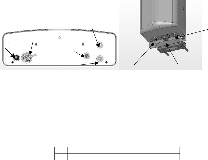
The Hub has the following interfaces and indicators as shown in Figure 2-5 and described below:
Figure 2-5 AX1255-SM (on left) and AX1255-VM Connectors (on right)
RF Input Port: AC surge protected and SCTE compliant female F-type connector for RF and power
connection to the cable network.
-20 dB Monitor Port: SCTE compliant female F-type connector for monitoring the downstream RF
signal.
Weather-proof Ethernet Port: RJ-45 connector for local connection of a PC and for VDC powering
over Ethernet (PoE).
Pin Function US modern T-568A
1 Ethernet Tx+ green-white
LED RJ-45
RF Input
Monitor Port
Ground
Stud
RJ-45
RF Input
Monitor Port

ARCXTEND USER MANUAL – R1.4, ISSUE 4
Copyright 2005 Arcwave, Inc. 7
2 Ethernet Tx- green
3 Ethernet Rx+ orange-white
4 PoE - lower voltage (-) blue
5 PoE - lower voltage (-) blue -white
6 Ethernet Rx- orange
7 PoE - higher voltage (+) brown-white
8 PoE - higher voltage (+) brown
Table 2-1: Table for 10/100 Mbits Ethernet wiring and Power over Ethernet
Power-on, LED: Indicates that the Hub is receiving VAC or VDC power. (AX1255-SM Only)
Hub Configurations
The Hub model number format is AX1UV5-WW-XX where:
• “U” indicates frequency band(s) of operation where “2” is for 5.8 GHz downstream and 5.3
GHz upstream operation and “4” is for 5.8 GHz only.
• “V” is “0”, for Upstream Only, or “5”, for Bidirectional
• “WW” indicates mounting orientation, VM, for Vertical Mount, or SM, for Strand Mount).
• “XX” indicates antenna transmit beamwidth (“90”, for 90-Degree Horizontal Beamwidth and
“25”, for 20-Degree Horizontal Beamwidth).
All Hubs support both 60 to 90 VAC powering over coax and 24 VDC powering over Ethernet
(POE).
The standard network hub configurations are:
Downstream
Range
Model
number
Downstream
Frequency
Band
Upstream
Frequency
Band
Mounting
Orientation
Transmit
Antenna
Beamwidth 64
QAM
256
QAM
Bidirectional Systems
AX1255-
SM-90
5725 MHz –
5850 MHz
5250 MHz
- 5350
MHz
Horizontal 90 Degrees 1 Mile ¼ Mile
AX1255-
SM-25
5725 MHz –
5850 MHz
5250 MHz
- 5350
MHz
Horizontal 20 Degrees 2 Miles 1 Mile
AX1255-
VM-90
5725 MHz –
5850 MHz
5250 MHz
- 5350
MHz
Vertical 90 Degrees 2 Miles ½ Mile
Upstream Only, No remote monitoring. If remote monitoring is desired
use a standard AX1255-VM-90.
QPSK 16
QAM
64 QAM
AX1205-
VM-90
5725 MHz –
5850 MHz
5250 MHz
- 5350
MHz
Vertical 90 Degrees
8 Miles 4 Miles 2 Miles
Table 2-2: Hub Configurations
ARCXTEND USER MANUAL – R1.4, ISSUE 4
Copyright 2005 Arcwave, Inc. 8
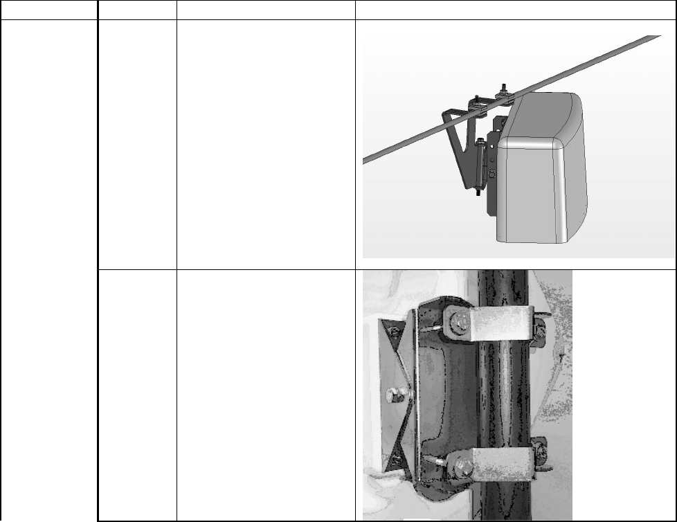
Hub Mounting Kits
Works with Model Description Image
Standard ARCXtend Strand
Mount Kit
Used to mount an
AX1255-SM to a
standard strand cable
Includes integrated
mounting bracket
providing 360° vertical
and +/- 30° horizontal
adjustment for rapid
and flexible antenna
alignment.
AX1255-SM
AX1255-
SMA
ARCXtend Strand
Mount Adaptor Kit,
Network Hub
Used to mount an
AX1255-SM in the
horizontal position on a
1-1/4 to 2-3/8 O.D. pipe
mount
ARCXTEND USER MANUAL – R1.4, ISSUE 4
Copyright 2005 Arcwave, Inc. 9
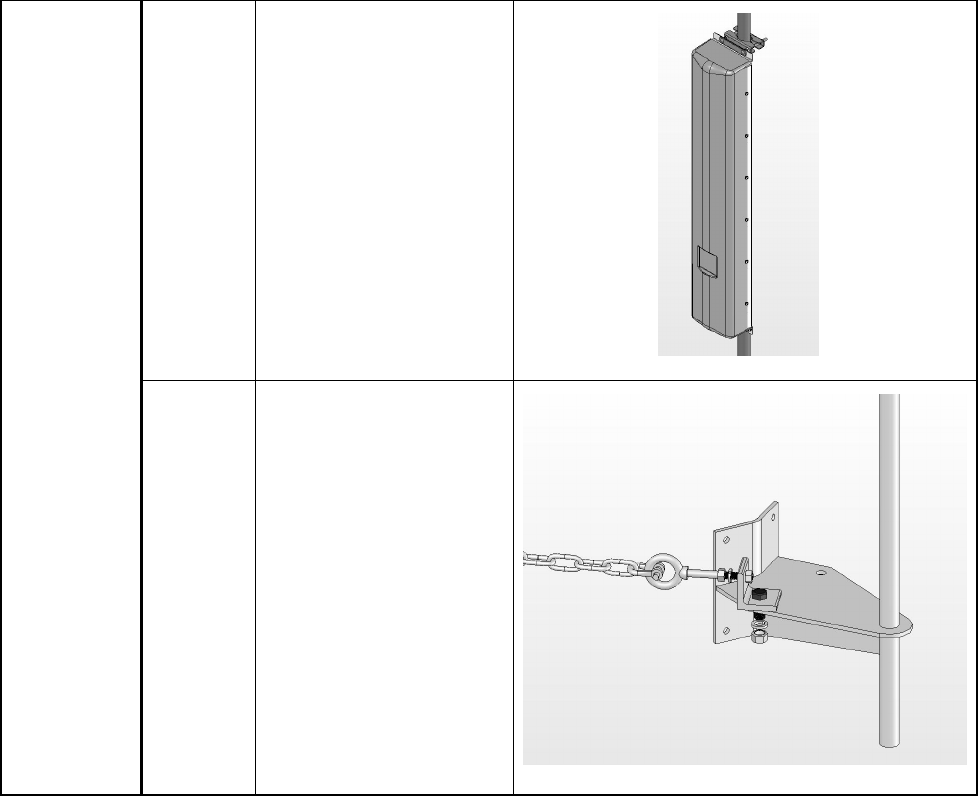
AX1255-
MMK
ARCXtend Mast Mount
Kit, Network Hub
Included with all
AX1255-VM Hubs
Enables the Hub to
mount to a mounting
pipe with an outside
diameter from 1 1/4“ to
2 3/8”
AX1255-VM
AX1255-
PMK
ARCXtend Pole Mount
Kit, Network Hub
Includes the AX1255-
MMK
Enables the Hub to be
mounted to a standard
diameter wooden utility
pole using a chain or
four bolts
The Hub attaches to a
pile welded to the
bracket using the mast
mount kit
Table 2-3 Hub Mounting Options
ARCXtend CPE
The CPE is small footprint weatherproof radome, as show in Figure 8 that can be easily mounted
on a rooftop or side of a building to provide connectivity to the wireless network. It contains an
integrated transceiver and a narrow-beam antenna that can be easily aligned to receive the
Wireless DOCSIS signal from a Network Hub. The CPE is roughly one foot square and supports
low cost installation using the same hardware and skills as a small satellite dish.
The CPE has a single, female-type F connector for both VDC power and RF signal. It is located on
the back of the unit as show in Figure 2-6.
ARCXTEND USER MANUAL – R1.4, ISSUE 4
Copyright 2005 Arcwave, Inc. 10
Figure 2-6: CPE RF Connector
CPE Configuration and Accessories
The CPE model number format is AX3U55-WW-XX where:
• “U” indicates frequency band(s) of operation where “2” is for 5.8 GHz downstream and 5.3
GHz upstream operation and “4” is for 5.8 GHz only.
• “WW” indicates mounting orientation, VM, for Vertical Mount, or SM, for Strand Mount).
• “XX” indicates antenna transmit beamwidth (“90”, for 90-Degree Horizontal Beamwidth).
All CPEs support 12 VDC powering over Coax.
The standard CPE models are:
Upstream Range
Model
number
Downstream
Frequency
Band
Upstream
Frequency
Band
Mounting
Orientation
Transmit
Antenna
Beamwidth QPSK 16
QAM
64
QAM
AX3155-
VM-90
5725 MHz –
5850 MHz
5250 MHz –
5350 MHz
Vertical 90 Degrees 8 Miles 4 Miles 2 Miles
Table 2-4: CPE Models
The standard CPE accessories are:
Power Packs and DC Inserters
• AX3155-PS-12: 120 VAC 60 Hz/12 VDC adaptor and DC Inserter
ARCXTEND USER MANUAL – R1.4, ISSUE 4
Copyright 2005 Arcwave, Inc. 11
Downstream Signal Attenuators
• AX3155-ECF-10: 10 dB Downstream Attenuator for attenuating the DS signal level without
affecting the US signal level
• AX3155-ECF-20: 20 dB Downstream Attenuator for attenuating the DS signal level without
affecting the US signal level.
ARCSmartTM 2.0 Intelligent Network Management
Arcwave’s ARCSmart intelligent network management combines an embedded DOCSIS 2.0
compliant cable modem, SNMP-compliant Arcwave Enterprise MIB (management information
base), and an upgradeable processing engine with upgradeable software to support low cost
configuration, monitoring, and troubleshooting of an ARCXtend Network Hub (Hub). Specific
capabilities include:
• DOCSIS 2.0-compliant embedded cable modem (ECM)
• SNMP-compliant Arcwave Enterprise MIB
• HTTP-based User Interface
• ARCSmart firmware upgrade
DOCSIS 2.0 Compliant ECM
Each Hub includes a hardened DOCSIS 2.0-compliant cable modem (ECM) supporting in-band
communication over standard DOCSIS channels with ARCSmart. For proper operation of
ARCSmart Advanced Network Features the ECM and all cable modems served by the Hub must be
on the same downstream and upstream DOCSIS channels at all times.
The ECM firmware can be upgrading using TFTP and normal cable modem firmware upgrade
procedures.
Watchdog Timer
This embedded cable modem also includes a system watchdog timer with a peripheral bus
interface. It provides a method for resetting the host, upon expiration of the timer value, to heal
system hangs due to software bugs, power spikes, and so on. The watchdog timer period and
prescale values are programmable and are protected by dual keyed-lock state machines. Disabling
of the watchdog timer is protected by both hardware tie-offs and a triple keyed-lock state machine.
Resetting (kicking) of the watchdog timer is provided through a dual keyed-lock state machine.
SNMP-compliant Arcwave Enterprise MIB
The Arcwave Enterprise MIB is compliant with SNMP version 1, 2, and 3 and fully accessible and
manageable using third-party SNMP-based network management tools. It contains all Hub
management, performance, and configuration data. Appendix A of this manual contains a
description and element definitions for the Arcwave Enterprise MIB as implemented in the Hub. The
compilable “arcwave.mib” file is included on each product documentation CD and can also be
downloaded from the Arcwave website.

ARCXTEND USER MANUAL – R1.4, ISSUE 4
Copyright 2005 Arcwave, Inc. 12
Setting the SNMP public and private strings
For the SNMP Community String (Private), Read-Write Access set the following MIB to the
indicated value as show in Table 2-5:
DOCSIS MIB Name Object ID Type Value
docsDevNmAccessStatus 1.3.6.1.3.69.1.2.1.7.1 Integer 4
docsDevNmAccessIp 1.3.6.1.3.69.1.2.1.2.1 IpAddress 255.255.25
5.255
(means any
NMS
station)
docsDevNmAccessIpMask 1.3.6.1.3.69.1.2.1.3.1 IpAddress 0.0.0.0
docsDevNmAccessCommunity 1.3.6.1.3.69.1.2.1.4.1 OctetString private (the
name you
want)
docsDevNmAccessControl 1.3.6.1.3.69.1.2.1.5.1 Integer 3
Table 2-5 SNMP Community String (Private), Read-Write Access
For the SNMP Community String (Public), Read-Write Access set the following MIB to the indicated
value as show in Table 2-6 Read-Only Access:
DOCSIS MIB Name Object ID Type Value
docsDevNmAccessStatus 1.3.6.1.3.69.1.2.1.7.1 Integer 4
docsDevNmAccessIp 1.3.6.1.3.69.1.2.1.2.1 IpAddress 255.255.25
5.255
(means any
NMS
station)
docsDevNmAccessIpMask 1.3.6.1.3.69.1.2.1.3.1 IpAddress 0.0.0.0
docsDevNmAccessCommunity 1.3.6.1.3.69.1.2.1.4.1 OctetString public (the
name you
want)
docsDevNmAccessControl 1.3.6.1.3.69.1.2.1.5.1 Integer 2
Table 2-6 SNMP Community String (Public), Read-Write Access
HTTP-based user interface
The Hub contains an HTTP-based web tool that can be used to interface to the unit.
ARCSmart firmware upgrade
ARCSmart provides the ability to upgrade its firmware using a TFTP (Trivial File Transfer Protocol)
protocol. This is accomplished using the Firmware Download Information table on the Arcwave MIB
Maintenance page:
ARCXTEND USER MANUAL – R1.4, ISSUE 4
Copyright 2005 Arcwave, Inc. 13
TFTP server IP Address: Enter the TFTP (Trivial File Transfer Protocol) server’s IP address.
Firmware Upgrade Filename: Enter the file name of the ARCSmart controller firmware to be
downloaded to the Hub.
Start Upgrade: Click the “Apply” button to initiate the download. The download of the new
controller firmware will take one to two minutes. The download can be verified by refreshing the
page. The version number of the downloaded firmware should be displayed in the Firmware
Version Number box under in the Real Time Monitor Information table.
Advanced Network Management Features
Plug-n-Play
ARCSmart has the ability to automatically program and modify Hub settings with the same DOCSIS
downstream and upstream channel information being received by the ECM. To activate this feature,
set Auto Frequency Set to “ENABLE”. With this activate, whenever the ECM detects a change in
the downstream or upstream channel it will propagate this change to the appropriate Hub settings.
This includes information sent in a Station Maintenance Message (SMM) Notification-US Frequency
Change.
Downstream frequency agility
ARCSmart has the ability to automatically “tune” to a downstream channel on the cable network. To
activate this feature, set Cable Interface Control to “On”.
Settable Hub Transmit Power
The wireless transmitter output of the Hub, determined by the Select Downstream Power setting,
can be set for on of three modes:
• High or 19 dBm
• Medium or 13 dBm
• Low or 3 dBm
Note: The “High” power setting is for use with the AX1255-SM-90 and AX1255-VM-90 Network
Hubs. Use of the “High” power setting with the AX1255-SM-25 cancels the FCC certification and
voids the operator’s authority to operate the unit in the 5.8 GHz band.
PureBurst Ingress Noise Suppression
PureBurst effectively functions as a door. When there is no wireless upstream signal being received
the Hub, this door is closed. When closed, the Hub does not output any noise onto the cable plant.
Therefore, when other subscribers are transmitting in the upstream to the CMTS, the wireless hub
does not contribute to the cable plant’s noise floor.
When a cable modem utilizing the wireless upstream link is transmitting the door is open. During
this time the Hub allows the upstream signal plus Hub related thermal noise to pass onto the cable
plant. Closing of the door results in the cable plant’s U/S noise floor returning to its previous level.
ARCXTEND USER MANUAL – R1.4, ISSUE 4
Copyright 2005 Arcwave, Inc. 14
This ensures that the only upstream signal affected by the hub’s internal upstream noise is the
wireless burst signal as scheduled by the CMTS. This allows many wireless hubs employing
PureBurst to be connected to the same cable plant without raising the upstream plant noise floor
and affecting other users sharing the same cable plant.
This feature is enabled by default.
ARCXTEND USER MANUAL – R1.4, ISSUE 4
Copyright 2005 Arcwave, Inc. 15
PRE-DEPLOYMENT PLANNING
Hub Site Selection
A suitable location for the Hub is one that provides an acceptable line of sight (LOS) wireless link to
the CPE(s) located at the customer site(s). An acceptable wireless link is one within the working
range of Hub and with line of sight to the customer sites.
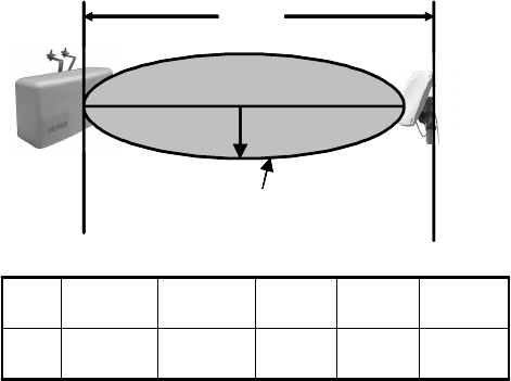
Line of Site
Line of sight is defined as a path between the Hub and CPE that is free of obstructions in the
Fresnel zone. Obstructions could be trees, buildings, street signs, etc. An accepted rule of thumb is
that LOS conditions exist when there are no physical obstructions within 60% of the Fresnel zone
(obstruction free zone). Obstructions can be trees, buildings, street signs, etc. The Fresnel Zone
clearance is determined by the distance between the Hub and CPE as shown in Figure 3-1.
Figure 3-1: Fresnel Zone Clearance Requirement
Range
The maximum range, assuming a clear Fresnel zone, is determined by the Hub type, downstream
modulation, and the mounting height of the Hub. The range, arc, and coverage area of all three
models of Hubs are given in Tables 3-1, 3-2, and 3-3.
Modulation Range Arc Area
Downstream Wireless Link
64 QAM (DS)
256 QAM (DS)
1 mile
0.25 miles
1.6 miles
0.4 miles
0.8 sq-miles
0.05 sq-miles
Upstream Wireless Link
CPE
CPE
Network
Network
Hub
Hub
r
r
d
d
Fresnel Zone must
Fresnel Zone must
be clear of
be clear of
obst ruct ions
obstructions
12 feet9 ft.6 ft.4 ft.3 ft.
r
2 miles1 mile½ mile1,000 ft. 500 ft.
d
CPE
CPE
Network
Network
Hub
Hub
r
r
d
d
Fresnel Zone must
Fresnel Zone must
be clear of
be clear of
obst ruct ions
obstructions
12 feet9 ft.6 ft.4 ft.3 ft.
r
2 miles1 mile½ mile1,000 ft. 500 ft.
d

ARCXTEND USER MANUAL – R1.4, ISSUE 4
Copyright 2005 Arcwave, Inc. 16
QPSK (US)
16 QAM (US)
64 QAM (US)
3 miles
2 miles
1 mile
4.2 miles
3.1 miles
1.6 miles
7.0 sq-miles
3.1 sq-miles
0.8 sq-miles
Table 3-1: AX1255-SM-90 Strand Mounted Network Hub (18 ft off the ground)
Modulation Range Arc Area
Downstream Wireless Link
64 QAM (DS)
256 QAM (DS)
2 miles
1 mile
3.1 miles
1.6 miles
3.1 sq-miles
0.8 sq-miles
Upstream Wireless Link
QPSK (US)
16 QAM (US)
64 QAM (US)
6 miles
3 miles
2 miles
9.4 miles
4.7 miles
3.1 miles
28.0 sq-miles
7.0 sq-miles
3.1 sq-miles
Table 3-2: AX1255-SM-25 Strand Mounted Network Hub (18 ft off the ground)
Modulation Range Arc Area
Downstream Wireless Link
64 QAM (DS)
256 QAM (DS)
2 miles
0.5 miles
3.1 miles
0.8 miles
3.1 sq-miles
0.20 sq-miles
Upstream Wireless Link
QPSK (US)
16 QAM (US)
64 QAM (US)
6 miles
3 miles
2 mile
9.4 miles
4.7 miles
3.1 miles
28.0 sq-miles
7.0 sq-miles
3.1 sq-miles
Table 3-3: AX1255-VM-90 Vertical Mounted Network Hub (100 ft off the ground)
Equipment Location
A simple method for choosing the location of the Hub uses a map1 of the area to be covered. Draw
two circles taking the customer site(s) to be covered as its center and the maximum range of each
Hub type as the circle’s radius. Try first to find locations on your plant that fall within the range of the
AX1255-SM-90 and the AX1255-SM-25 and then the AX1255-VM-90.
The AX1255-SM-90 provides maximum coverage area at the expense of limited range, whereas the
AX1255-SM-25 provides maximum range at the expense of limited coverage area. The AX1255-
1 A network map with street and building information is ideal for this activity.
ARCXTEND USER MANUAL – R1.4, ISSUE 4
Copyright 2005 Arcwave, Inc. 17
VM-90 provides maximum coverage and maximum range but requires access to a building or tower
for mounting. Locations on building or towers are availably but generally involve a lease agreement
with the owner and the site must be within a thousand feet of the cable plant.
Once you have identified possible sites for the Hub, drive out to these locations and determine
which, if any of them, provide a line of site path to the customer site(s) to be served. The simplest
way to do this is, using a spotting scope, find the other end of the path and determine if it meets the
Fresnel zone criteria. A more accurate approach would be to use a range finder to measure the
height of the highest obstruction in the path and GPS to measure the distance. If you find that none
of the Hub sites will work then you need to go back to the map and try and locate alternative
locations.
Checking for Interference
ARCXtend maps the upstream DOCSIS channel to a high frequency and a low frequency pair in the
5.250 to 5.350 GHz band. This mapping is fixed and based solely on the frequency of the upstream
DOCSIS channel. Determine the corresponding wireless channels the upstream frequency used in
your cable plant. Check for interference at both frequencies and note which of these channels are
free of interference, as it will be used for the deployment. If you can’t find free spectrum for the
downstream and upstream signals then you will need to find another location.
Handheld wireless LAN spectrum analyzers covering the 5.250 to 5.350 range and capable of
identifying signals regardless of origin, like the BANTAM INSTRUMENTS Model 425A, are ideal for
locating potential interference.
CPE Site Selection
Height and Location
A suitable location for the CPE is one that provides an acceptable line of sight (LOS) wireless link,
as previously defined, to the Hub. This requires the CPE to be placed high enough on the rooftop to
provide the required Fresnel zone clearance. Using the setup shown in Figure 3-2 monitoring, the
optimal height and location can be determined by monitoring the Signal Level reading on the AR100
Signal Strength Meter. Monitoring the Signal Level meter on the AR100, the optimal CPE height
and location will be indicated by maximum signal level readings.
The CPE are that it should be located to the edge of the building closet to the Hub. If the CPE were
to be mounted towards the middle or back of the building, the incoming wireless signal can be
reflected by the rooftop impairing the performance of the link. It is also advisable to select a location
near to the rooftop grounding system to have a short, low resistance path and within 300 feet of an
AC power source. The routing path for the coaxial cable that connects the CPE to the cable modem
is also worked following your normal guidelines.
ARCXTEND USER MANUAL – R1.4, ISSUE 4
Copyright 2005 Arcwave, Inc. 18
Figure 3-2: CPE Site Survey Setup
Checking for Interference
ARCXtend supports the assignment of any downstream RF channel to one of the twenty available
downstream wireless channels. The available carriers and the corresponding CPE downstream RF
channel are given in Table 3-4. By examining the CPE downstream frequency spectrum we can
determine which of the wireless channels is free of interference.
* Pending FCC approval.
Table 3-4: Downstream Hub to CPE Channel Mapping
Hub
Downstream
Wireless
Channel
CPE
Downstream RF
Channel
Hub
Downstream
Wireless Carrier
Channel
CPE
Downstream RF
Channel
Hub
Downstream
Wireless Carrier
Channel
CPE
Downstream RF
Channel
5729 MHz 429 MHz 5771 MHz 471 MHz 5813 MHz 513 MHz
5735 435 5777 477 5819 * 519
5741 441 5783 483 5825 * 525
5747 447 5789 489 5831 * 531
5753 453 5795 495 5837 * 537
5759 459 5801 501 5843 * 543
5765 465 5807 507
Telescoping
Mast
CPE
LNB
CPE Wall
Mount
Adaptor
AR100
Signal
Strength
Meter
RX
Power
Inserter
Spectrum
Analyzer
RF Power
To AM
p
RF TO
TV
Power in
ARCXTEND USER MANUAL – R1.4, ISSUE 4
Copyright 2005 Arcwave, Inc. 19
Tap
CATV Plant
ARCXtend
Subscriber
Transceiver
Cable Modem
ARCXtend
Hub
Transceiver
CATV Channel
EIA Channels 7 - 134
90 MHz - 855 MHz
ARCXtend Air Frequency
5729 MHz - 5843 MHz
CM Receive Frequency
429 MHz - 543 MHz
LAN or USB
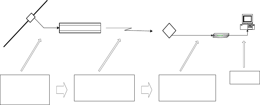
Channel Plan
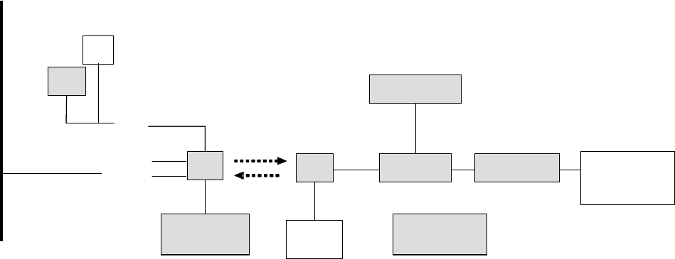
Downstream Configuration
The ARCXtend downstream block diagram is illustrated in Figure 3-3. Note that the North
American DOCSIS 64 QAM or 256 QAM downstream signal is 5.25 MHz wide and is transported
within a standard 6 MHz wide channel throughout the CATV plant and the ARCXtend system. All
downstream frequencies indicated are the center frequency of the 6 MHz wide channel.
Figure 3-3: ARCXtend Downstream Block Diagram
Downstream Block Diagram
The DOCSIS cable modem downstream channel on the CATV plant is already established in the
working cable modem system. At the time of installation the ARCXtend Hub is automatically
configured to the CATV downstream channel. Any EIA channel between 7 and 134, inclusive, may
be utilized. Table A-3 in Appendix A provides a list of these channels and their corresponding
center frequencies.
The downstream output of the ARCXtend Hub is the over-the-air frequency in the range of 5729
MHz through 5843 MHz. Any frequency in this range can be chosen from Table 3-4, which
determines the corresponding cable modem receive frequency. Note from the table that the cable
modem downstream receive frequency is always [air frequency – 5300 MHz]. The ARCXtend
standard downstream air frequencies were chosen to ensure that the corresponding cable modem
downstream receive frequencies are centered on standard EIA CATV channels to enable the
fastest possible cable modem downstream scan.
In summary, any CATV downstream channel may be employed as input into the Hub, and any
specified air frequency between 5729 and 5843 MHz may be chosen, but the cable modem receive
frequency (channel) is determined from the air frequency only. Note that the downstream CATV
ARCXTEND USER MANUAL – R1.4, ISSUE 4
Copyright 2005 Arcwave, Inc. 20
Tap
CATV Plant
ARCXtend
Subscriber
Transceiver
Cable Modem
ARCXtend
Hub
Transceiver
CATV Upstream
Frequency
5 MHz - 42 MHz
ARCXtend Air Frequency
5258 MHz - 5342 MHz
CM Transmit
Frequency
5 MHz - 42 MHz
LAN or USB
frequency may be different than the cable modem receive frequency. This is generally not a
concern as most DOCSIS systems on which there is only one DOCSIS downstream channel on the
cable network do not specify the CM receive frequency in the CM configuration file, rather they let
the CM find the downstream on its own.
Upstream Configuration
The ARCXtend upstream block diagram is illustrated in Figure 4-2. Note that the North American
DOCSIS (Version 1.0 and 1.1) QPSK or QAM upstream signal is up to 3.2 MHz wide. DOCSIS 2.0
upstream signals can be as much as 6.4 MHz wide. All frequencies specified in this section are the
center frequency of the particular signal.
Figure 3-4: ARCXtend Upstream Block Diagram
Upstream Block Diagram
The cable modem (CM) is commanded by the downstream signal to transmit at a specific upstream
frequency between 5 MHz and 42 MHz. Note that any upstream frequency may be selected.
Refer to Figure 3-4 from right to left. The ARCXtend Subscriber Transceiver (CPE) up converts the
CM upstream signal to the 5300 MHz band and transmits two copies of the signal: 5300 MHz-[CM
transmit frequency] and 5300 MHz+[CM transmit frequency].
For example, if the CM upstream transmits frequency is 22.5 MHz; the ARCXtend CPE will
simultaneously transmit the signal on two air frequencies: 5277.5 MHz and 5322.5 MHz.
In summary, the CM upstream transmit frequency determines the two upstream air frequencies
transmitted by the ARCXtend CPE. The ARCXtend Hub selects either the high or low air frequency
and passes the user data upstream to the CATV plant at the original CM transmit frequency.
ARCXTEND USER MANUAL – R1.4, ISSUE 4
Copyright 2005 Arcwave, Inc. 21
ARCXtend Multiple Hub Configurations
Downstream
If multiple ARCXtend Hubs are to be installed such that more than one Hub is visible (line of sight)
from any ARCXtend subscriber transceiver (CPE), additional measures must be taken. A receiver
will not operate properly if it “sees” signal on the same frequency from more than one transmitter
such that the two or more signals arrive at the receiver at levels within approximately 25 dB of each
other. (If the desired signal is greater than approximately 25 dB stronger than the undesired, the
receiver will function).
Since the ARCXtend downstream configuration can map the CATV plant downstream channel to
any of the specified air frequencies, the solution is to choose different downstream air frequencies
for each visible ARCXtend Hub.
Upstream
Similarly, if multiple ARCXtend Hubs are to be installed to cover a larger geographic area than can
be accommodated by the antenna pattern of one Hub, but in close enough proximity that more than
one Hub can “see” the upstream signal from a particular CPE operating at the same upstream air
frequency at levels within approximately 25 dB of each other, the combined signal on the upstream
will be unusable.
The solution is to utilize different upstream CM transmit frequencies, and therefore different
upstream air frequencies, in the different Hubs. This means that each CM transmit frequency will
be passed upstream into the CATV plant. Note that this will require the CATV plant and CMTS to
accommodate these separate upstream channels. Recall that DOCSIS supports multiple upstream
channels working with a single downstream. All CMs served by any given Hub must be provisioned
for the same upstream frequency.
IP Network Preparation
Hub’s Default IP Address
The ARCXtend Network Hub (Hub) utilizes an IP address in the cable network for remote
management and automatic of configuration of Hub parameters.
If an IP address is not provided for the Hub, it can be only accessed via the local Ethernet interface
and using the default IP address:
• IP address of 192.168.100.1
• Subnet mask 255.255.255.0
Cable Network IP Address
If remote management or plug-n-play installation is desired, the Hub must be assigned an IP
address by the cable network. This is accomplished by provisioning the MAC ID of the Hub’s
embedded cable modem (ECM) MAC ID into the networks OSS/NMS.

ARCXTEND USER MANUAL – R1.4, ISSUE 4
Copyright 2005 Arcwave, Inc. 22
DHCP Server Setup
The Hub’s ECM requires an IP address and its own unique configuration file. In order for the ECM
to be assigned an IP address and be loaded with the proper configuration file the following actions
are required:
Set up a DHCP pool on your server for the ARCXtend ECMs to ensure that the ECM is properly
configured and addressed.
ECM Configuration File
The ECM has its own DOCSIS standard format configuration file, ecm.cfg, which is pre-loaded at
the factory and loaded on the ECM. A copy is also included on the documentation CD and
downloadable from the customer support page of the www.arcwave.com web site. The
configuration file should be edited be prior to installation to confirm with cable network specific
settings.
The configuration file for the ARCXtend ECM contains the following information:
• Downstream channel parameters (optional)
• UCD which specifies the upstream channel parameters (optional)
• Authentication parameters (optional)
• Registration parameters (mandatory)
• ECM firmware upgrade file name (optional)
The Hub ECM and attached wireless subscriber cable modem must be assigned to the same
upstream frequency and must not be part of an upstream group supporting multiple upstream
channels.
TCP/IP Port Filtering
TCP/IP port filtering is the practice of selectively enabling or disabling Transmission Control
Protocol (TCP) ports and User Datagram Protocol (UDP) ports on computers or network devices.
The following ports must be open for SNMP, HTTP, and TFTP applications to be performed on the
Hub:
• Port 161/162 for SNMP
• Port 80 for HTTP
• Port 69 for TFTP
Hub Electrical Interface
The Hub is connected to the cable plant using a power-passing tap spliced in at the desired location
on the cable plant.
AC Powering and Surge Protection
In strand mount applications, the Hub is powered through the input RF port. The Hub is capable of
60 VAC or 90 VAC powering power. The internal power supply provides a regulated 24 VDC output
ARCXTEND USER MANUAL – R1.4, ISSUE 4
Copyright 2005 Arcwave, Inc. 23
over an ac input between 45 Vrms and 125 Vrms with a line frequency from 50 Hz through 60 Hz. A
20-ampere fuse is furnished in the power supply module and provides over current protection for ac
power applied to the input. SCTE compliant surge protection is provided in the power supply.
Connections are made using standard pin-type connectors with a nominal center-conductor
diameter of 0.067 inches. The minimum length of the center-conductor pin is 1.5 inches and the
maximum length is 1.65 inches. Longer pins can extend past the center-conductor seizure
mechanism and degrade the match. Extremely long pins can result in a short circuit.
DC Powering
The Hub can also be powered through the weather-protected Ethernet port using Power-over-
Ethernet. The power level at the Ethernet Port should be between 18 and 26 VDC. DC power
should be applied to the CAT5 cable using the “Injector” provided by Arcwave.
Inset RJ-45 pin configuration
RF Signal Power Level and Quality
The Hub requires a downstream path RF power level at the input RF port of between -5 dBmV and
+25 dBmV. The modulation error ratio (MER) going at the input RF port should be within the
budgeted range for the wireless link. In general a minimum MER of 35 dB is required for 256 QAM
and 31 dB is required for 64 QAM downstream path modulations.
CPE Electrical Interface
The CPE is powered over and connects to the cable modem, using standard coaxial cable.
AC Powering and Surge Protection
The CPE is powered through the RF output port. The CPE is powered with 12 VDC. Arcwave
provides a 120 VAC CPE power pack and a power inserter approved for use with the CPE. The
CPE must typically be located within 100 feet of the power pack to insure adequate powering of the
CPE.
Lightning Protection
The CPE must be mounted at least 2 feet below the highest point at the site to minimize the
likelihood of lightning strikes. The location should be properly grounded for lightning protection to all
applicable national (National Electric Code, sections 820-33 and 820-40) and local codes.
To protect the customer equipment from surges on the coaxial cable that is connecting the CPE to
the cable modem, the installation of an SCTE compliant surge protector is required.

ARCXTEND USER MANUAL – R1.4, ISSUE 4
Copyright 2005 Arcwave, Inc. 24
INSTALLATION AND COMMISSIONING
Proper installation and verification are critical elements to achieving optimal wireless performance.
This section provides cable plant installation professionals with a step-by-step procedure and
troubleshooting guide for successfully deploying Arcwave’s ARCXtend Wireless Plant Extension
Solution.
Action items are preceded with by the )symbol.
Prerequisites
Professionals using this process should be trained and familiar with installation and troubleshooting
of cable drops, cable modems, and with the operation of ARCXtend.
Pre-deployment planning should be completed including the IP network preparation required for
initialization of the embedded cable modem.
Link Budget
Wireless link planning and RF link budgeting should be completed prior to attempting an ARCXtend
installation. The measured signal level values for the wireless link and cable network interfaces
should be recorded during the installation and commissioning process.
Personnel
This guide is designed to be used by cable plant installation professionals. It can be performed by
one person with the proper training, wireless link planning, and tools. It is recommended, however,
that two people be present during the alignment process between the hub and CPE: one person
located at the network hub and the other at the CPE.
Equipment and Materials
Equipment Source Use
AR100 Signal Strength
Meter
Arcwave CPE Alignment
Digital Cable TV
Installation Meter
Sunrise Telecom Hukk
CM500 or equivalent
Hub installation & link
commissioning
7/16” & ½” wrench Multiple Hub and CPE installation
Spotting Scope or
Binoculars
Multiple Hub site selection
Range Finder Multiple Hub site selection
GPS Receiver Multiple Hub site selection
Bucket Truck Multiple Hub Installation
Walkie Talkies or Cell
phones
Multiple Communicate between
Hub and CPE sites
Laptop Computer w/ Serial
& Ethernet Ports
Multiple Hub monitoring and
configuration

ARCXTEND USER MANUAL – R1.4, ISSUE 4
Copyright 2005 Arcwave, Inc. 25
Material Source Use
ARCXtend Network Hub
Arcwave
AX1255-SM-25, AX1255-
SM-90, AX1255-VM-90
Wirless interface to cable
network on plant side
ARCXtend CPE
Arcwave
AX3155-VM-12
Wirless interface to cable
network on customer side
ARCXtend CPE Power
Adaptor and DC Inserter
Arcwave
AX3155-PS-12
Powering CPE
ARCXtend Network Hub
Management Kit, M/N
Arcwave
AX1255-IFK-232
Hub Interface Cable Kit
10dB and 20dB low pass
attenuators
Arcwave
AX3155-ECF-10
AX3155-ECF-20
Attenuate CPE
downstream output power
level
Power Passing Tap Multiple Provides RF signal and
power for network hub
CPE Mounting Hardware Valmont, Patriot Antenna
Systems, Wade Antenna
Ltd.,
Mounting CPE at the
installation site
RG-6 coaxial cable and
male “F” type connectors
Multiple Connecting the network
hub to the power passing
tap
Connecting the CPE to the
cable modem
Ground device Multiple Grounding the CPE
installation
Surge Protector Array Solutions Model 310 Protects the cable modem
and susbcriber equipment
from damage due to a
lightning strike.
Table 4-1: Installation Equipment & Materials
Equipment Ordering and Staging
Once you have completed the wireless link planning process you are ready to order or pull from
inventory the necessary equipment. At this point you should verify you have all the equipment and
tools required to complete the installation.
ARCXTEND USER MANUAL – R1.4, ISSUE 4
Copyright 2005 Arcwave, Inc. 26
Hub installation & commissioning
Setup the Hub Power and RF Connection
)Install a power passing tap at the desired hub location on the cable plant and verify that the AC
power level, the downstream RF signal power level, and the downstream modulation error rate
(MER) meets ARCXtend requirements as listed below:
1. Verify that the input power range is between 50 Vac and 110 Vac nominal.
2. Verify that the input the downstream RF signal level is between -5 dBmV and +25 dBmV.
3. Verify that the downstream modulation error ratio (MER) going into the hub is within the
budgeted range for this link. In general a minimum MER of approximately 35 dB is required
for 256 QAM operation and 31 dB is required for 64 QAM operation.
D
A B
F
C
G
E
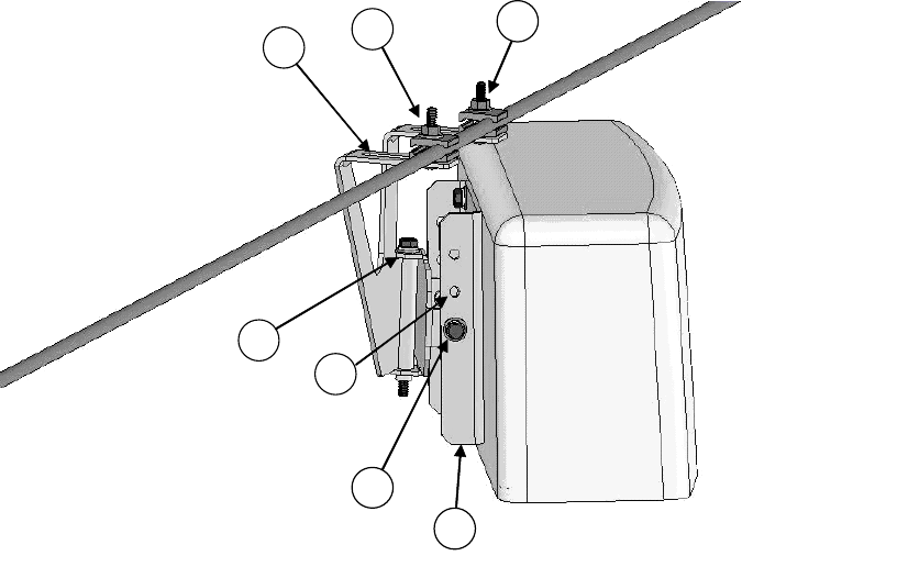
Figure 4-1: Hub Installation Diagram
Secure the Hub to the Strand
)Using the antenna pattern decals located on the top and side of the hub, align the hub antenna
in the approximate direction of customer site(s). Install as show in Figure 4-1 per the steps
provided below using a 7/16” combination or socket wrench. It is recommended that the hub be
located on the strand as close as possible to the utility pole to minimize swaying in windy
conditions.
1. Attach the bracket to the messenger strand with the hanger bolts at A and B. Tighten the
hanger bolts lightly. If the existing cable bundle lashed below the messenger strand is
ARCXTEND USER MANUAL – R1.4, ISSUE 4
Copyright 2005 Arcwave, Inc. 27
sufficiently thick to interfere with the top of the Hub cover, the two elevation adjustment bolts
D can be relocated to a pair of upper holes G on the back plate F.
2. Loosen horizontal adjustment bolt C and rotate the hub so that it is pointed at the center of
the area to be served by this hub. Tighten azimuth adjustment bolt C.
3. Loosen the two elevation adjustment bolts at D (one on each side of the mounting bracket)
and tip the Hub back plate F so that it is parallel to the azimuth adjustment bolt C. Tighten
the elevation adjustment bolts lightly.
4. Loosen the hanger bolts A and B and slide them in the slots E at the top of the mounting
bracket until the hub balances and the back plate F is perpendicular to the ground. Tighten
the hanger bolts A and B.
5. Loosen the two elevation adjustment bolts at D (one on each side of the mounting bracket)
and tip the hub up or down to point it at the center of the area to be served. Tighten the two
elevation adjustment bolts D.
6. Ensure that all bolts are tightened securely.
7. Using a 75 ohm F connector coaxial cable, connect the Hub to the power passing tap.
8. This completes the physical installation of the Hub.
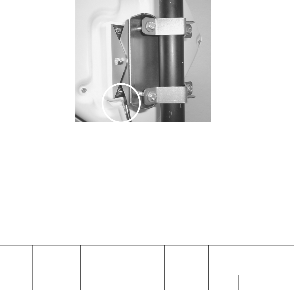
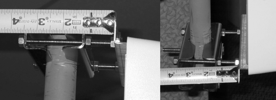
(Optional) Secure the Hub to the Mast
Install the Hub per the steps provided below using a 7/16” combination or socket wrench.
1. Slide the mast mount brackets over the mounting pipe. Snug the bracket bolts.
2. Rotate the Hub towards the customer sites to be covered.
3. Adjust the down tilt of the Hub by increasing the gap between the Hub and the bracket at the
top and decreasing the gap between the Hub and the bracket at the bottom as show in
Figure 4-2.
Figure 4-2: Mast Mount Kit Bracket Offset
Establish a Local Connection to the Hub
)Connect a laptop computer to the RJ-45 Ethernet port of the Hub and connect to the Hub vai an
internet browser with the IP address set to 192.168.100.1.
The hub should respond with the “Enter Network Password” prompt.
ARCXTEND USER MANUAL – R1.4, ISSUE 4
Copyright 2005 Arcwave, Inc. 28
Enter the “user id” and password. The default user id “admin” and password is “arcwave”.
Verify the Embedded Cable Modem has achieved operational maintenance state.
) Referring to the Cable Status page of the user interface:
Verify that the Embedded Cable Modem has successfully completed its initialization sequence. If it
has not, troubleshoot per normal procedures.
Set up and verify the Hub’s cable plant interface
) Referring to the Arcwave MIB Information page of the user interface:
• Verify that the Upstream Frequency and CATV EIA Input Channel settings are correct. If
Cable Interface Control and Automatic Frequency Set are enabled these values will be
entered automatically based on the values being used by the ECM. You can override these
values by disabling the Cable Interface Control and Automatic Frequency Set features and
entering them manually,
• Verify that DCE Lock is set to true.
Set up and verify the Hub’s wireless interface
)Referring to the Real Time Monitor Information table on the Arcwave MIB page of the user
interface:
• Set the Downstream Air Frequency.
• Set Select Downstream Power level the appropriate setting:
a. High for use with AX1255-SM-90 and AX1255-VM-90 Model Hubs operating with
64 QAM downstream modulation and links greater than ¼ mile.
b. Medium for use with all model Hubs operating with 256 QAM downstream
modulation at any link and 64 QAM modulation with links less than or equal to ¼
mile.
c. Low for use with all model Hubs at links below 500 feet.
Note: The “High” power setting is for use with the AX1255-SM-90 and AX1255-VM-90 Network
Hubs. Use of the “High” power setting with the AX1255-SM-25 cancels the FCC certification and
voids the user’s authority to operate the unit in the 5.8 GHz band.
• Verify that Downstream Enable and Upstream Enable are set to true.
If the Cable Interface Control is enabled and the EMC is operational, the Upstream
Attenuation level is set automatically based on the upstream transmit power level of the
ECM. If the EMC is not operation, then the Upstream Attenuation level must be set
manually. A good starting point is 30 dB.
• Verify that Downstream Lock and Upstream Lock are set to true.
ARCXTEND USER MANUAL – R1.4, ISSUE 4
Copyright 2005 Arcwave, Inc. 29
a. For a Select Downstream Power setting of High or Medium verify that the
Downstream Transmit Power setting indicates 10 or greater .
b. For a Select Downstream Power setting of Low verify that the Downstream
Transmit Power setting indicates Below 10.
Set the Hub Management Mode
)Referring to the Real Time Monitor Information table on the Arcwave MIB page of the user
interface:
1. Enter Title, if desired, otherwise it defaults to the MAC address of the ECM.
2. Set the Alarm Destination IP address, if desired.
3. Choose the method for managing the Hub by setting the Select Control Mode:
If Control via HTTP is chosen, then the Hub can be managed remotely over the cable network or
locally using the Ethernet port using the embedded a PC and the HTTP-based user interface.
If the Control via SNMP is chosen, then the Hub can be managed remotely over the cable network
using SNMP.
CPE installation
)Install the CPE mounting hardware (not supplied by Arcwave) per the manufacturer’s
recommended procedures and in accordance with the National Electric Code and local
ordinances.
Note: The CPE accommodates a mounting pipe with of 1-1/4” to 2-3/8” in diameter and the CPE
and mounting pipe require a minimum of 12 inches clearance on all sides for optimal performance.
Note: The CPE should be located as close to the edge of the building nearest the hub as possible.
When the CPE is mounted towards the middle or back of the building, the incoming wireless signal
may be reflected by the rooftop impairing the performance of the link. The CPE must be placed
high enough on the rooftop to provide the required Fresnel zone clearance (Fresnel zone =
blockage free zone).
Affix the CPE mounting mast
)Referring to Figure 4-3, loosen the "Side/side alignment bolts and slide the CPE over the
mounting pipe. Visually align the CPE in the direction of the Hub and snug the side/side
alignment bolts to hold the CPE in place.
ARCXTEND USER MANUAL – R1.4, ISSUE 4
Copyright 2005 Arcwave, Inc. 30
Mounting bracket (included)
Elevation alignment bolt
F-connector (before taping)
Pipe
Side/side alignment bolt
Figure 4-3: CPE Mounting Diagram
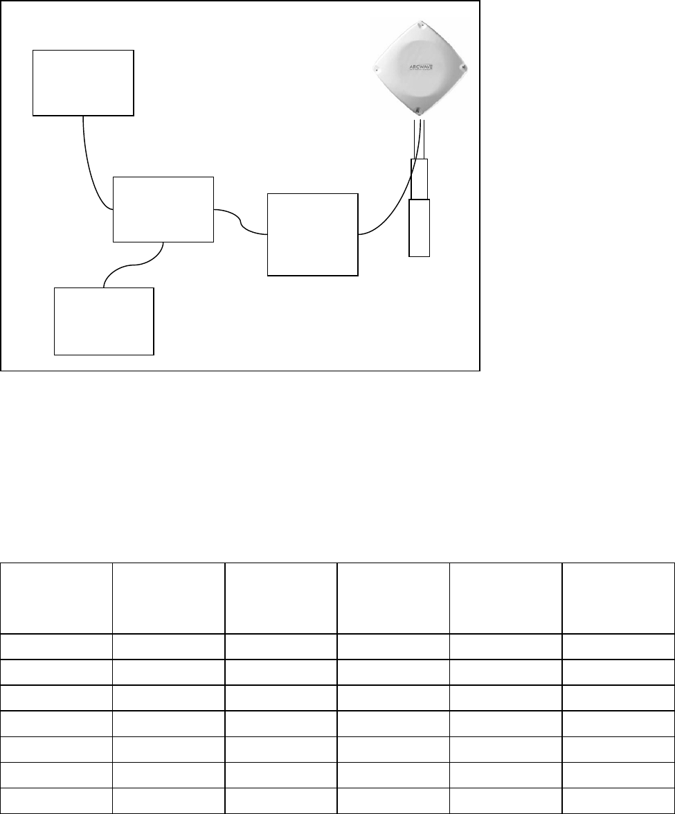
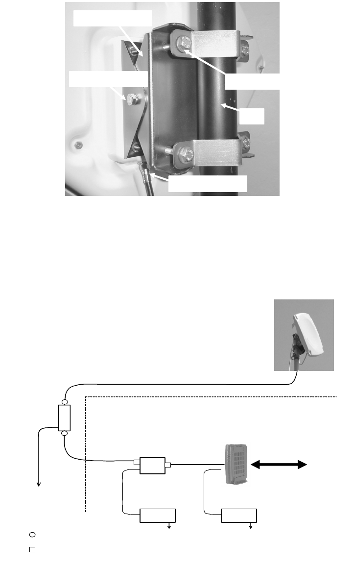
Install the Coaxial Cable and Ground Connection
)Install the coaxial cable and ground connection as shown in Figure 4-4:
DC
Inserter
P/Supply P/Supply
Grounding
Device
Building
Entrance
Ground
LAN/PC
CPE
RG-6 Cable
(length up to 200 ft.)
RG-6 cable
RG-6 Cable
Cable Modem
120 VAC 120 Vac
Weatherproof F-type
Indoor F-type connector
Figure 4-4: CPE Wiring Diagram
ARCXTEND USER MANUAL – R1.4, ISSUE 4
Copyright 2005 Arcwave, Inc. 31
)Connect an RG-6 coaxial cable to the F connector located on the rear of the CPE. Waterproof
the connection using a suitable method such as taping with Coax-Seal2 or Scotch #88.
Note: Be sure to leave sufficient cable slack for final CPE alignment and ensure that the cable runs
directly downward from the connector to avoid water running down the cable and into the F
connection.
)Route the coaxial cable to the building entry point utilizing UV-resistant tie-wraps and staples or
cable clamps as required.
Note: UV-rated cable should be used outdoors. In some buildings plenum-rated or riser-rated
cable is required for inside runs.
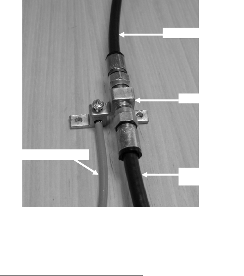
)Mount a CATV system standard grounding device in Figure 5-5 as close as possible to the point
of cable entry into the building. Connect the grounding device to a suitable “grounding
electrode” as required per local building codes.3
)Connect the RG-6 coaxial cable from the CPE to the grounding device and waterproof all
outdoor F connectors.
To Subscriber Transceiver
Grounding device
Ground wire (green or bare)
To power inserter
& cable modem
Figure 4-5: Grounding device at subscriber premises
2 Coax-Seal is available from Universal Electronics, Inc. Phone: 828-293-2222.
3 The National Electric Code, sections 820-33 and 820-40, describes this requirement in detail.
ARCXTEND USER MANUAL – R1.4, ISSUE 4
Copyright 2005 Arcwave, Inc. 32
)Inside the subscriber premises, route the RG-6 from the building entrance point to where the
cable modem will be used.
)Terminate and install an F connector on the cable. Connect the cable from the CPE to the “to
antenna” F female connector of the power inserter.
Install the power adaptor and DC inserter
)Install the DC inserter as show in Figure 4-6. Connect the power adaptor to the DC inserter as
show in Figure 4-4 and figure 4-6. Plug the power adaptor into a surge protected AC power
receptacle. Note the AC Power Pack must be within 300 feet of the CPE.
Figure 4-6: Power Inserter and AC/DC adaptor
CPE Alignment
Note: The higher the received signal level, the less likely the system will be affected by
interference, plant variations, and geography. High received signal strengths are obtained by proper
alignment of the CPE to the Hub.
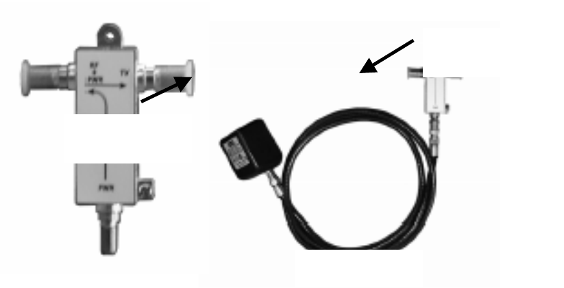
Connect the signal strength meter
)Connect the port of the DC inserter going to the cable modem to the RX side of the AR100
signal strength meter (depicted in Figure 4-7) or equivalent signal strength meter .
To CPE (RF &
PWR)
To Cable Modem
To Power Pack

ARCXTEND USER MANUAL – R1.4, ISSUE 4
Copyright 2005 Arcwave, Inc. 33
Figure 4-7: AR100 Signal Strength Meter (SSM)
)Align the CPE for maximum signal strength as follows:
1. Using a 7/16” wrench (open end, box or socket), loosen the two elevation alignment bolts
until the CPE can be tilted up or down by hand, but will hold its position.
2. Observe the display of the alignment device being employed and orient the CPE up and
down to achieve a maximum peak signal. Adjust the gain control on the AR100 as needed.
3. Tighten the elevation alignment bolts slightly.
4. Using the same wrench loosen the four mounting bolts so the CPE can be oriented side to
side by hand.
5. Observe the display of the alignment device being employed and orient the CPE side to side
to achieve a maximum peak signal.
6. Tighten the elevation alignment bolts slightly.
7. Repeat the elevation (tilt up or down) adjustment, and then the azimuth (side by side)
adjustment once again.
8. Tighten the elevation alignment (tilt) bolts, taking care not to over tighten.
9. Tighten the mounting bolts firmly, but do not over tighten.
10. Disconnect the coaxial cable from the RX side of the AR100 and connect to the cable
modem.
Verify CPE output signal at input to cable modem
)Using a Digital Cable TV Installation Meter, measure the downstream RF channel power level.
The typical target power level range is between 0 and +7 dBmV.
DS received power level is too
high
DS received power level is too
low
DS signal is not present
If the DS received power level
is too high install one or more
10 dB (AX3155-ECF-10) or 20
dB (AX3155-ECF-20) low
pass attenuators between the
power inserter and the cable
Select Downstream Power
setting is correct.
Reduce the cable and RF
hardware loss between CPE
and cable modem or add bi-
Verify integrity of in-building
cabling and power.
Make sure CPE Power
Adaptor and DC inserter are
installed properly.

ARCXTEND USER MANUAL – R1.4, ISSUE 4
Copyright 2005 Arcwave, Inc. 34
modem.
If more than 30 dB of
attenuation is required and the
Select Downstream Power
setting is High, change the
setting to Medium.
directional amplification.
Redo the CPE alignment
process
Verify the wireless range and
LOS path between Hub and
CPE are within specified
limits.
Check DC power level at input
to CPE.
Check coaxial cable
connections.
Verify the wireless range and
LOS path between Hub and
CPE are within specified
limits.
Cable Modem Installation
)Connect the cable modem to the modem side of the DC power inserter as shown in 4-4 and
Figure 4-6. Complete installation of the cable modem using normal procedures.
If the cable modem registers with the network
Verify the downstream signal level
) Using the cable modem’s diagnostic interface, check that the downstream signal level is within
the desired cable modem operating range.
DS received power level is too high to cable
modem
DS received power level is too low
If the DS received power level is too high
install one or more 10 dB (AX3155-ECF-10)
or 20 dB (AX3155-ECF-20) low pass
attenuators between the power inserter and
the cable modem.
If more than 30 dB of attenuation is required
and the Select Downstream Power setting is
High, change the setting to Medium.
Check that the Select Downstream Power
setting is correct.
Reduce the cable and RF hardware loss
between CPE and cable modem or add bi-
directional amplification.
Redo the CPE alignment process
Verify the wireless range and LOS path
between Hub and CPE are within
specified limits.
Table 4-2: DS received power level troubleshooting
Verify the upstream signal level
)Using the cable modem’s diagnostic interface, check the upstream signal (US) level is within the
desired operating range.

ARCXTEND USER MANUAL – R1.4, ISSUE 4
Copyright 2005 Arcwave, Inc. 35
US transmit power of the cable modem is too
high
US transmit power of the cable modem is
too low
If the US transmit power is too high, decrease
the Upstream Attenuation in the Arcwave MIB
Maintenance page of the user interface
setting by an amount equal to the desired
decrease in the upstream power level. i.e. if
the US transmit power is 50 dBmv and it
should be 45 dBmV then reduced the
Upstream Attenuation setting by 50 dBmV
minus 45 dBmV, or 5 dBmV.
Reduce the cable and RF hardware loss
between CPE and cable modem or add
amplification.
Redo the CPE alignment process
Verify the wireless range and LOS path
between Hub and CPE are within specified
limits.
If the US transmit power is too low,
increase the Upstream Attenuation in the
Arcwave MIB Maintenance page of the
user interface setting by an amount equal
to the desired increase in the upstream
power level. i.e. if the US transmit power
is 40 dBmv and it should be 45 dBmV
then increase the Upstream Attenuation
setting by 50 dBmV minus 45 dBmV, or 5
dBmV.
Table 4-3: US transmit power level troubleshooting
If the cable modem doesn’t register with the network
If the cable modem does not register with the network, troubleshoot as follows:
Problem Solution
Does not detect and lock on DS channel Check to see if the the MER of the
downstream RF channel is within specificied
limits:
MER should be at or above 27 dB for 64
QAM, and 31 dB for 256 QAM. If it is not,
check the following:
Verify that the Select Downstream Power
setting is correct for the downstream
modulation and wireless range.
Change Downstream Air Frequency to a
different channel to rule out interference.
Verify the wireless range and LOS path
between Hub and CPE are within specified
limits.
Does not detect and lock on US channel Using the cable modem’s diagnostic
interface, see if the cable modem is seeing

ARCXTEND USER MANUAL – R1.4, ISSUE 4
Copyright 2005 Arcwave, Inc. 36
the correct upstream RF channel.
If it does see the channel and can’t lock on,
reduce the Upstream Attenuation setting at
the Hub.
If it does not see the channel, and Cable
Interface Control and Automatic Frequency
Set are enabled, verify that the Hub ECM and
the subscriber cable modem are assigned to
the same upstream frequency and are
excluded from an upstream load balancing
group.
If it does not see the channel, go to the Hub
and check the following:
Using -20 dB monitor port of the Hub verify
the Hub is receiving a wireless signal from
the CPE.
If there is a signal, vary the Upstream
Attenuation setting at Hub until the cable
modem locks on the US channel.
If there is not a signal:
Verify that the cable modem transmitter is
working.
Replace the CPE
Cable Modem does not receive an IP address Perform normal cable modem installation
troubleshooting procedures.
Cable modem does not receive time of day
(ToD)
Perform normal cable modem installation
troubleshooting
Cable modem does not receive config file Perform normal cable modem installation
troubleshooting
Cable modem initializes, receives a config file,
and then reboots
Make sure the configuration file being
downloaded to the cable modem does not
contain downstream channel information. The
downstream RF channel frequency being
delivered by the CPE to the Cable Modem is
different than what is received at the Hub.
Table 4-4: Cable modem registration

ARCXTEND USER MANUAL – R1.4, ISSUE 4
Copyright 2005 Arcwave, Inc. 37
Link Verification
Downstream path measurements
DS Modulation Expected Performance Troubleshooting
64 QAM 27 dB MER
10-8 BER, post-error correction
Inspect the constellation to
determine the type of impairment
affecting the signal and troubleshoot
accordingly.
Verify the plant MER is greater than
required for the downstream
modulation
256QAM 31 dB MER
10-8 BER, post-error correction
Verify the downstream power level
into the cable modem is between -6
dBmv and +15 dBmV.
Inspect the constellation to
determine the type of impairment
affecting the signal and troubleshoot
accordingly.
Verify the plant MER is greater than
required for the downstream
modulation
Table 4-5: Downstream path measurements
Upstream path measurements
Parameter Expected Performance Troubleshooting
CM output Power +40-52 dBmV typical.
58 dBmV max for QPSK, 55
dBmV for 16 QAM
If CM output power is too high,
reduce the amount of loss in the
drop to allow for margin or reduce
the Upstream Attenuation setting.
BER 10-8 BER, post-error correction
for QPSK and 16 QAM
To test BER on the return
path, the analyzer can ping the
CMTS with a packet of known
data. The ping command will
return the packet to the
analyzer from the CMTS on
the downstream path. To be
sure the packet does not go
any further than the CMTS
port; the analyzer can use a
trace route command to the
Verify RF return path performance
with the wireless link. This can be
done by looking at the BER of the
cable modem in the hub.
Check for interference in the 5.250
to 5.350 GHz band. If interference
is present, try changing the
upstream frequency HI/LO setting.

ARCXTEND USER MANUAL – R1.4, ISSUE 4
Copyright 2005 Arcwave, Inc. 38
dynamic host configuration
protocol (DHCP) server to
determine the route. The first
Internet protocol (IP) address
in the route to server is the
CMTS port.
Table 4-6: Upstream Path Measurements
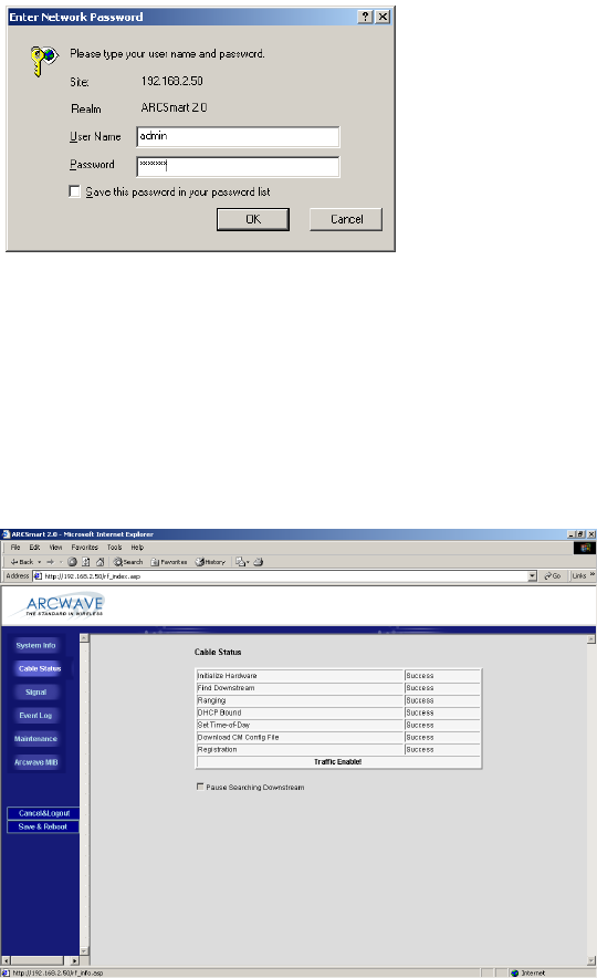
ARCXTEND USER MANUAL – R1.4, ISSUE 4
Copyright 2005 Arcwave, Inc. 39
USER INTERFACE
The Hub contains an HTTP-based web tool that can be used to interface to the unit. Following is a
guide to using this tool. The following functions are supported: System Info, Signal, Event Log,
Maintenance, and Arcwave MIB.
Accessing the Interface
To access the interface you first must be logged onto a computer that is in some way connected to
the Hub. This can be done either directly using the RJ-45 port on the Hub or through the cable
network. Enter the IP address of the Hub (default IP address on the Ethernet interface is
192.168.100.1) into the address bar of your browser and press the enter key on your keyboard.
Figure 5-1: Hub login screen
When the Hub is accessed the user is presented with a login screen (Figure 5-1). The user id is
‘admin” and the password is ‘arcwave” (all lower case without quotes). The user id and password
can be changed using the Maintenance page.
Cable Status Page
Figure 5-2: Cable Status page
ARCXTEND USER MANUAL – R1.4, ISSUE 4
Copyright 2005 Arcwave, Inc. 40
The Cable Status page is the default web page and contains information on the status of the ECM.
Figure 5-2 shows the results for a normal ECM connection to the cable network. If the ECM has
failed to connect properly to the cable network, fewer of the tasks will be registered as Success.
The first one not showing as Success will be the task that is failing.
Initialize Hardware The embedded modem check its hardware
Find Downstream The embedded modem find the available downstream
frequency
Ranging After the embedded modem locks onto the available
downstream. It will get the upstream information from CMTS
and try to find the available upstream channel. And it will try
the tuning the upstream power to make it has equivalent
power that CMTS requests to be.
DHCP Bound The embedded modem is getting IP address from DHCP
server
Set Time-of-Day The embedded modem is trying to synchronize the device
time with TOD (time of day) server. The modem still can get
registered even it fails in getting TOD response.
Download CM Config file The embedded modem is getting configuration file from TFTP
server. And the IP address of TFTP server should be
specified in DHCP options
Registration The embedded modem use the configuration parameters
inside Cable Modem config file and request service from
CMTS
Pause Searching Downstream Stop all the tasks from downstream searching. Thus the
embedded modem will not try to register with CMTS
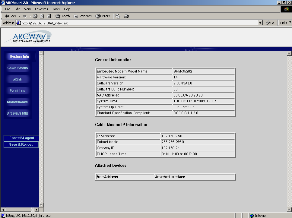
ARCXTEND USER MANUAL – R1.4, ISSUE 4
Copyright 2005 Arcwave, Inc. 41
System Info Page
Figure 5-3: System Info page
The System info page contains General Information on the ECM including hardware and software
revision, MAC address, and DOCSIS standard compliance. It also contains Cable Modem IP
information that provides important IP networking information required to access the ECM.
General Information
Embedded Modem Model Name The model name of the Modem that embedded inside
<ARCXtend 1255>
Hardware Version The hardware version of the embedded modem
Software Version The software version of the embedded modem
Software Build Number The minor software version of the embedded modem. Some
times if the same code were compiled in different time, it will
has different build number. Generally it will be “00”.
MAC Address The MAC address of the embedded modem. This is used to
provision the device to be access. This MAC address should
be added in the DHCP server behind CMTS Ethernet side.
And need to assign the MAC address with corresponding
ARCXTEND USER MANUAL – R1.4, ISSUE 4
Copyright 2005 Arcwave, Inc. 42
configuration to get service.
System Time The time that embedded modem get from TOD server and
the time-offset configure on DHCP server.
System Up Tome The duration from the last system boot up
Standard Specification Compliant The standard specification that embedded modem complies
with. DOCSIS 1.1/DOCSIS 2.0 stands for that this is a
DOCSIS 2.0 Modem and backward compatible with DOCSIS
1.1. If it shows DOCSIS 1.1 only that means this is a
DOCSIS 1.1 only cable modem.
Cable Modem IP Information
IP Address The IP address that embedded modem get from the DHCP
server
Subnet Mask The subnet mask of embedded modem that assigned from
DHCP server
Gateway IP The default gateway IP address of embedded modem that
assigned from DHCP server
DHCP Lease Time The lease time that embedded modem get from the DHCP
server
Attached Device
MAC Address The MAC address of other device that attached with this
embedded modem.
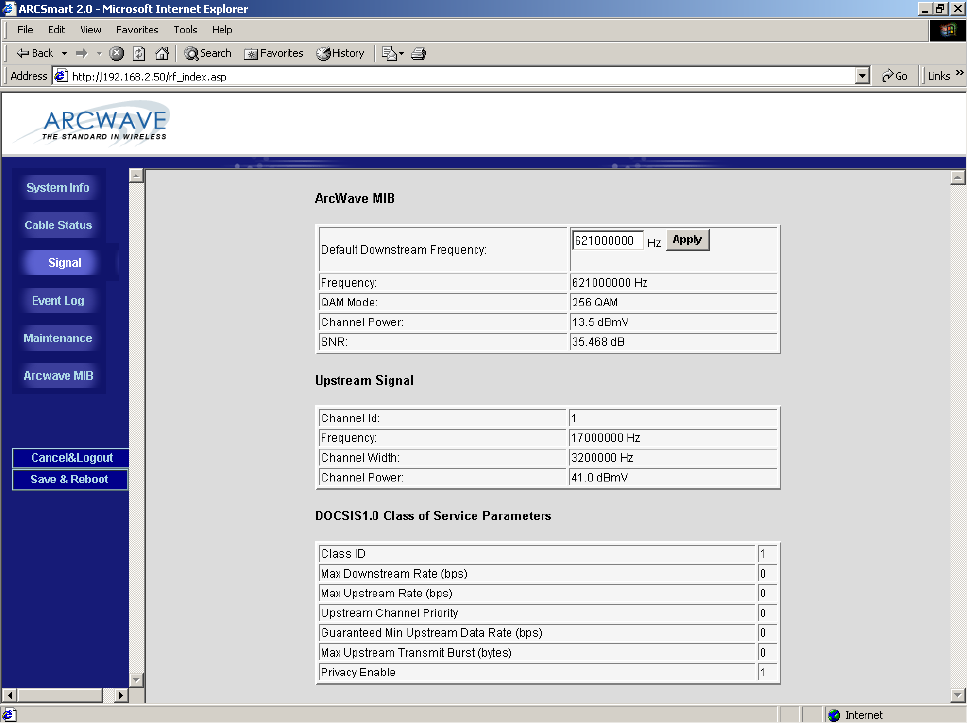
ARCXTEND USER MANUAL – R1.4, ISSUE 4
Copyright 2005 Arcwave, Inc. 43
Signal Page
Figure 5-4: Signal Page
The Signal Page contains information on the signal status of the upstream and downstream
DOCSIS channels:
Arcwave MIB
Default Downstream Frequency Optionally choose the frequency where the ECM should first
attempt to acquire the downstream RF channel. This setting
will speed up the downstream RF channel acquisition time by
instructing the ECM to go directly to the indicated frequency
where the RF channel is located.
Frequency The frequency of the downstream channel that ECM is locked
on.
QAM Mode The modulation of the downstream channel that ECM is
locked on.
Channel Power The power level that ECM receives at this location.
SNR The signal noise ratio that the ECM receives at this location.
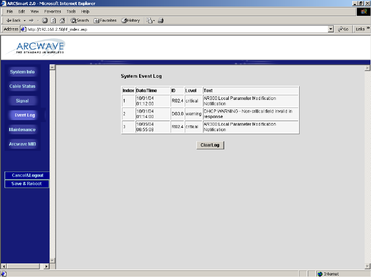
ARCXTEND USER MANUAL – R1.4, ISSUE 4
Copyright 2005 Arcwave, Inc. 44
Upstream Signal
Channel ID The ID of the upstream channel that ECM is either attempting
to, or is, locked on.
Frequency The frequency of that US channel ID
Channel Width The channel width specified for this US channel ID. (Specified
in upstream channel profile inside CMTS)
Channel Power The transmit power of the ECM. The Channel Power
displayed is 10 dB higher than the actual upstream power
level at the F connector on the Hub.
DOCSIS 1.0 Class of Service Parameters
Class ID Indicates the class of service ID.
Max Downstream Rate (bps) The maximum downstream data rate that the ECM is
permitted to use.
Max Upstream Rate (bps) The maximum upstream data rate that the ECM is permitted
to use.
Upstream Channel Priority The preferred upstream channel ID for the ECM to use.
Guaranteed Min Upstream Data
(bps)
The minimum upstream data rate that is reserved for the ECM
to use.
Privacy Enable Enables the encryption of the frames transmitted using RF
signal over coaxial cable between CMTS and the ECM.
Event Log Page
Figure 5-5: System Event Log page
ARCXTEND USER MANUAL – R1.4, ISSUE 4
Copyright 2005 Arcwave, Inc. 45
The Event Log page contains event information for the ECM and ARCSmart. The Event Log is
presented in reverse chronological order, so the most recent log entry is at the top. Each entry in
the log is time stamped in the format MMDDYYhhmmss in GMT (Greenwich Mean Time). The time
stamp is replaced by asterisks if the cable modem has not yet acquired the time.
The event log is useful when diagnosing sporadic problems, and can reveal the reason for the ECM
having previously gone offline. Not every line in the log represents an error, even if it is flagged as
an error. Log entries of events affecting the data service are flagged Critical, Alert, or Emergency.
DOCSIS standard events are reported for the ECM and following are the valid ARCSmart 2.0
events:
System Event Log
Index The sequence in index of according to the time that event
occurred.
Date/Time The date and time that the event occurred
ID The abbreviation and classification of the event inside the
device. Where;
T01 is equivalent to T1 timeout - Wait for UCD timeout
T02 is equivalent to T2 timeout - Wait for broadcast ranging
timeout
T03 is equivalent to T3 failure or timeout - Wait for ranging
response
T04 is equivalent to T4 failure or timeout - Wait for unicast
ranging opportunity.
T06 is equivalent to T6 failure - Wait for REG-RSP and REG-
ACK
That defined in CM-SP-RFIv2.0-I06-040804
Level The severity level of this event
Text The description of that event

ARCXTEND USER MANUAL – R1.4, ISSUE 4
Copyright 2005 Arcwave, Inc. 46
Event Syntax Event
Message
Text
Severity Customer
Symptom
Explanation of
event
/Corrective
Action
What will the
Customer
Experience
AR300 System Lock Lost The Unit
has lost lock
in the
Upstream or
Downstream
Critical Modems on
the
ARCXtend
system lose
sync
The transmitter
or receiver
module (or both)
has lost lock/
Clear alarms
and/or reset
power on unit &
check if
condition goes
away
Lost of traffic,
system
outage
AR300 Hub Dead The Unit is
dead.
Critical Modems on
the
ARCXtend
system lose
sync
The transmitter
or receiver
module or both
stop
communicating
with the control
module/ Clear
alarms and/or
reset power on
unit & check if
condition goes
away
Lost of traffic,
system
outage
AR300 Input voltage
outside of tolerance
Voltage
level is
either below
or above
tolerance
limits
Major This alarm
gets
displayed
The voltage
being supplied
to the Unit is
improper/ Check
voltage levels &
clear alarm
No
immediate
impact but
could result
in loss of
traffic,
system
outage.
AR300 Downstream
(Transmitter) Over
Temperature
The Unit is
operating
above Max.
operating
temperature
Major This alarm
gets
displayed
The Unit is
operating above
Max. operating
temperature/
Check operating
temperature,
clear alarm &
switch the unit
off if condition
does not go
away.
No
immediate
impact but
could result
in loss of
traffic,
system
outage.
AR300 DCE Unlocked or
Error
The Control
module has
lost lock
Critical Modems on
the
ARCXtend
system lose
sync
The Control
module has lost
lock/ Clear
alarms and/or
reset power on
unit & check if
condition goes
away
Lost of traffic,
system
outage
AR300 Upstream
(Receiver) Unlocked or
Error"
The
Upstream
module has
lost lock.
Critical Modems on
the
ARCXtend
system lose
sync
The Upstream
module has lost
lock/ Clear
alarms and/or
reset power on
unit & check if
condition goes
away
Lost of traffic,
system
outage
AR300
Dt(T itt)
The
Dt
Critical Modems on
th
The
Dt
Lost of traffic,
t
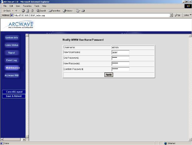
ARCXTEND USER MANUAL – R1.4, ISSUE 4
Copyright 2005 Arcwave, Inc. 47
Table 5-1: ARCSmart Event Messages
Maintenance
Figure 5-6: Maintenance Page
The Maintenance page provides the ability to change the user id and password. After entering the
new username, password and click on the Apply button. The username and password will updated
to the new settings.
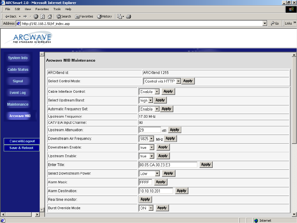
ARCXTEND USER MANUAL – R1.4, ISSUE 4
Copyright 2005 Arcwave, Inc. 48
Arcwave MIB page
Figure 5-6: Arcwave MIB page
The Arcwave MIB page contains information and configurable parameters pertaining to the
operation of the Hub and contained in the Arcwave Enterprise MIB.
Arcwave MIB Maintenance
ARCXtend Id Displays the Hub type, AX1255 or AX1455. This parameter is
used internally by ARCSmart to customize the user interface
based on the Hub type.
Select Control Mode Chose the method for managing the Hub.
If Control via HTTP is chosen, then the Hub can be managed
remotely over the cable network or locally via the Hub’s
Ethernet port, using a PC and the HTTP-based user interface.
If the Control via SNMP is chosen, then the Hub can be
managed remotely over the cable network using SNMP.
Cable Interface Control Chose “Enable” to turn-on the RF interface of the ECM and
ARCXTEND USER MANUAL – R1.4, ISSUE 4
Copyright 2005 Arcwave, Inc. 49
“Disable” to turn it off. This parameter is useful when the Hub
is used for a non-DOCSIS application, such as the wireless
transport of a digital video or CBR (constant bit rate) voice
signal, and there is no DOCSIS channel on the cable plant.
Selecting the “Off” setting will prevent the ECM from
continually scanning for a downstream channel, when none is
present. The default setting is “On”
Select Upstream Band Chose which of the two copies of the upstream wireless
carrier being transmitted by the CPE is to be received by the
Hub and passed to the cable network. This parameter is used
to avoid potential interference on the upstream channel.
If High is chosen, then the Hub will receive the upstream
wireless carrier at 5300 MHz plus the frequency of the
upstream channel
If Low is chosen, then the Hub will receive the upstream
wireless carrier at 5300 MHz minus the frequency of the
upstream channel.
For example, if the upstream frequency is 32.0 MHz, the
wireless signal will be transmitted at 5332 MHz (High) and
5268 MHz (Low). As show in Table 5-2, certain combinations
of downstream wireless carrier frequencies and upstream
channels require a specific High or Low setting for optimal
performance. For all other downstream wireless carrier
frequencies, the default setting is High.
Auto Frequency Set Chose “ENABLE” to have ARCSmart automatically program
the Hub CATV EIA Input Channel and Upstream Frequency
parameters with the same values used by the ECM. When set
to “ENABLE” these parameters will change whenever the
values are changed at the ECM. This setting is used for plug-
n-play installation of the Hub. Chose “DISABLE” when these
parameters will be set manually to values different than those
used by the ECM. In this mode, the values entered will persist
regardless of the values used by the ECM and across a Hub
power outage or reboot. This mode is useful when the Hub
will transmit a non-DOCSIS channel, such as digital video or
CBR voice.
The default setting is “ENABLE”. Note: “Cable Interface
Control” must be set to “Enable” in order for this element to be
set to “Enable”.
Upstream Frequency Displays the frequency of the upstream channel that is being
received by the Hub.
CATV EIA Input Channel Displays the EIA standard channel number of the downstream
channel that is being received by the Hub.
Upstream Attenuation Chose the amount of attenuation (in dB) in the upstream
receive path of the Hub.
ARCXTEND USER MANUAL – R1.4, ISSUE 4
Copyright 2005 Arcwave, Inc. 50
If “99” is entered, ARCSmart will automatically set the
attenuation based on the upstream channel transmit power
out of the ECM.
If any other value in the valid range from 0 to 64 is entered,
that the attenuation is set to that value.
This parameter is used to increases or decreases the
upstream channel transmit power of a cable modem
connected wirelessly to a Hub. Increasing the attenuation will
cause the CMTS to increase the cable modem’s upstream
channel transmit power. Decreasing the attenuation will cause
the CMTS to decrease the cable modem’s upstream channel
transmit power. The change in the attenuation and the change
in the upstream channel transmit power, while loosely related,
is not one to one.
Note: “Cable Interface Control” must be set to “Enable” in
order for this element to be set to “99” (Automatic Upstream
Attenuation setting).
Downstream Air Frequency Chose the downstream wireless carrier frequency.
Valid settings for AX1255 model Hubs are: 5729, 5735, 5741,
5747, 5759, 5765, 5771, 5777, 5783, 5789, 5795, 5807, 5813,
5819, 5825, 5831, 5837, and 5843 (in MHz).
The downstream channel frequency out of the CPE is the
Downstream Air Frequency minus 5300 MHz. The default
setting is 5759.
Downstream Enable Chose “TRUE” to turn on the downstream wireless transmitter
and “FALSE” to turn it off. The default setting is “TRUE”.
Upstream Enable Chose “TRUE” to turn on the upstream wireless receiver and
“FALSE” to turn it off. The default setting is “TRUE”.
Enter Title Enter a 40 characters alphanumeric string. The default
setting is the MAC address of the ECM. This parameter can
be used to give a unique identifier for the Hub.
Select Downstream Power Chose the downstream wireless transmitter power setting.
If “High” is selected, the transmit power is set to 19 dBm. (For
use with AX1255-VM-90 and AX1255-SM-90 Hubs only.)
If “Medium” is selected, the transmit power is set to 13 dBm.
If “Test” is selected, the transmit power is set to 3 dBm.
Alarm Mask Enter the hex value of the events that are to be masked. All
0’s masks all alarms, all F’s lets all alarms through, individual
alarms are as follows:
Definition of mmmm failure code (Logical OR of the bits)
ARCXTEND USER MANUAL – R1.4, ISSUE 4
Copyright 2005 Arcwave, Inc. 51
Bit 0: 1 = System Lock Lost
Bit 1: 1 = Hub Dead
Bit 2: 1 = Input voltage outside of tolerance
Bit 3: 1 = Downstream (Transmitter) Over Temperature
Bit 4: 1 = DCE Unlocked or Error
Bit 5: 1 = Upstream (Receiver) Unlocked or Error
Bit 6: 1 = Downstream (Transmitter) Unlocked or Error
Bit 7: 1 = Local modification notification
Alarm Destination Enter the IP address where SNMP traps are to be sent by the
Hub.
Clear Alarms Click on the “Apply” button to clear all alarms. (presented in
the “Event Logs” page)
Real time monitor Click on the “Apply” button to refresh the Real Time Monitor
display.
Burst Override Mode Chose “On” to disable PureBurst and “Off” to enable
PureBurst. When no traffic is present on the upstream cable
interface, PureBurst mutes the interface preventing the
introduction of ingress noise into the cable network.
Firmware Download Information
ARCXtend Id Displays the Hub type, AX1255 or AX1455. This parameter is
used internally by ARCSmart to customize the user interface
based on the Hub type.
TFTP server IP Address Enter the TFTP (Trivial File Transfer Protocol) server’s IP
address.
Firmware Upgrade Filename Enter the file name of the ARCSmart controller firmware to be
downloaded to the Hub.
Start Upgrade Click the “Apply” button to initiate the download. The
download of the new controller firmware will take up to two
minutes. The download can be verified by refreshing the
page. The version number of the downloaded firmware should
be displayed in the Firmware Version Number box under in
the Real Time Monitor Information table.
Arcwave MIB Real Time Monitor Information
Firmware Version Number: Displays the ARCSmart firmware version number.
Hardware Version Number: Displays the ARCSmart AX300 module hardware revision
number.
DCE Lock: Displays the status of the Hub cable network interface in the
downstream direction. It will display “TRUE” if the Hub is

ARCXTEND USER MANUAL – R1.4, ISSUE 4
Copyright 2005 Arcwave, Inc. 52
receiving a downstream channel and “FALSE” if it is not.
Downstream Lock: Displays the status of the Hub wireless transmitter. It will
display “TRUE” if the Hub is tuned to transmit at the
downstream wireless carrier frequency.
Downstream Transmit Power: Displays the power level of the Hub wireless transmitter into
the antenna.
Upstream Lock: Displays the status of the Hub wireless receiver. It will display
“TRUE” if the Hub is tuned to receive at the upstream wireless
carrier frequency.
Power Supply Voltage: Displays the DC voltage at the ARCSmart AX300 module. It
indirectly reflects the status of the AC adaptor.
Upstream Power Level: Displays the approximate upstream transmit power level. It is
the upstream transmit power level of the ECM minus 10
dBmV.
Transmitter Temperature: Displays the temperature in degrees Celsius at the surface of
the Hub wireless transmitter module.
DS Wireless Carrier
Frequency (MHz)
Upstream Channel Center Frequencies
(MHz) Default High / Low Setting
5729 and 5735 29.5 through 30.4
This combination is not
allowed and the DS will
automatically be changed
to 5741.
5729 and 5735 30.5 through 42.4 High
5741 13.5 through 26.4 High
5747 13.5 through 26.4 High
5753 13.5 through 26.4 High
5759 5.5 through 10.4 High
5765 5.5 through 10.4 High
5771 5.5 through 18.4 Low
5777 5.5 through 18.4 Low
5783 5.5 through 18.4 Low
5789 21.5 through 34.4 Low
5795 21.5 through 34.4 Low
5801 21.5 through 34.4 Low
5807 37.5 through 43.4 Low
5813 37.5 through 43.4 Low
5819 High
5825 High
5831 High
5837 High
5843 High
5741 through 5843 29.5 through 30.4 Low
5729 through 5843 If not otherwise shown above High
Table 5-2: Default Upstream Band Setting
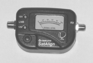
ARCXTEND USER MANUAL – R1.4, ISSUE 4
Copyright 2005 Arcwave, Inc. 53
ACCESSORIES
ARCXtend Accessories
The following accessories are available from Arcwave to use with the ARCXtend solution. To
purchase accessories, contact your sales representative.
• AR100 Signal Strength Meter – For use in CPE alignment.
Figure 6-1: AR100 Signal Strength Meter

ARCXTEND USER MANUAL – R1.4, ISSUE 4
Copyright 2005 Arcwave, Inc. 54
SPECIFICATIONS
AX1255 Network Hub
Transceiver
Wireless Channels Downstream: 20, 6.0 MHz Channels
Upstream: 14, 3.2 MHz Channels
7, 6.4 MHz Channels
Wireless Frequency Range (TX) 5.725 to 5.850 GHz; (RX) 5.250 to 5.350 GHz
Maximum Transmit Output Power
High: +19 dBm (Note: The “High” power setting is for
use with the AX1255-SM-90 and AX1255-VM-90
Network Hubs. Use of the “High” power setting with the
AX1255-SM-25 cancels the FCC certification and voids
the user’s authority to operate the unit in the 5.8 GHz
band.)
Medium: +13 dBm
Low: + 3 dBm
RF Frequency Range 90 to 860 MHz (Downstream); 5 to 42 MHz (Upstream)
Downstream Modulation
Supported
64 QAM, and 256 QAM
Upstream Modulation Supported QPSK, 16 QAM, and 64 QAM
Downstream Input Signal Level
into the Hub
-5 to +25 dBmV
Upstream Output Signal Level out
of the Hub
+35 dBmV Typical
Upstream Receiver Noise Figure 3.5 dB Typical
Adjacent Channel Rejection Greater than 40 dB
Antenna
Horizontal Beamwidth (–3 dB)
Vertical Beamwidth (-3 dB)
Transmit Gain
Receive Gain
EIRP
AX1255-VM-90 AX1255-SM-90 AX1255-SM-25
90° 90° 20°
6° 20° 20°
13 dBi 10 dBi 20 dBi
16 dBi 10 dBi 16 dBi
31.5 dBm 28.5 dBm 32 dBm
Network Management
MIB
Remote
Local
SNMP MIB (Alarms, Parameters, Metrics)
SNMP or HTTP-bases User Interface
HTTP-bases User Interface
Mechanical, System, and Regulatory
Services Supported DOCSIS, Digital and Analog Video, CBR Voice, T1/E1
Input Power 60 or 90 Vac nominal; 45 to 125 Vac actual; or
+24 Vdc nominal
Internal Operating Power +24 Vdc nominal

ARCXTEND USER MANUAL – R1.4, ISSUE 4
Copyright 2005 Arcwave, Inc. 55
Power Dissipation 24 Watts Maximum (at 90VAC)
Operating Temperature Range –40°C to +65°C
Operating Humidity 100% condensing
Protocols SNMP v1/2/3, DOCSIS 2.0
Regulatory FCC, IC (Canada)
Connections DC Power and Data port RJ-45
Cable port F-Type female
-20 dB Monitor port F-Type female
Dimensions and Weight AX1255-VM-90 AX1255-SM-90/25
41” x 7” x 5”, 14 lbs. 17” x 7.5” x 5.6”, 6 lbs.
Table 7-1: AX1255 Specifications
AX3155 Customer Premise Antenna / Transceiver (CPE)
Transceiver
Wireless Channels Downstream: 20, 6.0 MHz Channels
Upstream: 14, 3.2 MHz Channels
Wireless Frequency Range (TX) 5.250 to 5.350 GHz; (RX) 5.725 to 5.850 GHz
Maximum Transmit Output Power +30 dBm EIRP
Receiver Noise Figure Less than 3.5 dB typical
DOCSIS Frequency Range 425 to 550 MHz (Downstream); 5 to 42 MHz
(Upstream)
Downstream Modulation
Supported
64 QAM and 256 QAM
Upstream Modulation Supported QPSK, 16 QAM, and 64 QAM
Upstream Input Signal Level +25 to +58 dBmV
Downstream Output Signal Level Variable, based on link distance; +20 dBmV Typical
Minimum Downstream Input
Signal Level to the Cable Modem
64 QAM: -15 to +15 dBmV
256 QAM: -6 to +15 dBmV
Receiver Noise Figure 3 dB Typical
Antenna
Horizontal Beamwidth (–3 dB)
Vertical Beamwidth (-3 dB)
Transmit Gain
Receive Gain
10°
20°
14 dBi
22 dBi
Mechanical, System, and Regulatory
Input Power 120 Vac Power Pack
Operating Power 18 Vdc Power of Coax
Maximum Distance from CPE to 300 feet

ARCXTEND USER MANUAL – R1.4, ISSUE 4
Copyright 2005 Arcwave, Inc. 56
Power Pack
Power Dissipation 5 Watts Maximum
Operating Temperature Range –40°C to +65°C
Operating Humidity 100% condensing
Regulatory FCC, IC (Canada)
Mounting 1-1/4” to 2-3/8” Pipe
Connections Cable port F-Type female
Dimensions and Weight 14-5/8” x 14-5/8” x 2-3/8”, 5.1 lbs.
Table 7-2: AX3155 Specifications

ARCXTEND USER MANUAL – R1.4, ISSUE 4
Copyright 2005 Arcwave, Inc. 57
Environment Specifications
The environmental specifications for the ARCXtend solution including the AX1255, AX3155 and
associated electrical and mechanical subassemblies are given in Table 9-3 below.
Requirement Specification
Altitude
Operating Low to 10,000 feet
Storage and Transportation Low to 50,000 feet
Ambient Temperature
Operating –40 to +65°C (Includes solar loading)
Storage –60 to +75°C
Humidity
Operating 5 to 100% RH Non-condensing
Storage 5 to 95% RH
Rain
Operating Wind driven rain of 5.8 in/hour at 70 MPH
May not cause a link outage, but can degrade
performance)
Survival No requirement
Water immersion No leaks at 15 PSI internal pressure for 10 seconds
Salt Spray Per Specification – Comcast 1000 hrs.
Wind
Operating (Hub): 112 MPH (180km/hr) with 1 inch radial ice
May not cause a link outage, but can degrade
performance.
The deviation of the antenna main beam axis should
not be more than 0.3 times the smaller of the two
azithumal and elevation HPBW as a general rule)
Survival (Hub)l: 125 MPH (200km/hr)
No significant loss of alignment after test
Vibration
Operating: 0.001 G2/Hz from 5-100 Hz (IEC 60068-2-6)
Survival: 0.01 G2/Hz from 5-100 Hz (IEC 60068-2-6)
Shock
Survival: IEC 60068-2-27
Packaged: 4 Ft. drop
Corrosion
Plated Surfaces: ASTM D-2247, ASTM B-117/DIN 75-302
Painted Surfaces: ASTM 117-B (Salt Spray), ASTM D3359, ASTM-
D4060
UV Resistance/Stability ASTM G-53/DIN 53-505
Lightning/ESD 20kA IEC 1000-4-5 8/20µs Waveform

ARCXTEND USER MANUAL – R1.4, ISSUE 4
Copyright 2005 Arcwave, Inc. 58
Surge Withstand Capability (Hub) CAT B3 6kV, 3kA Combination wave on all RF ports
CAT A3 6kV, 200A Ring Wave on DC power Port
CAT B3 6kA Combination wave on 120 Vac
Transformer Input
Table 7-3 Environmental Specifications
CUSTOMER SUPPORT
Following is a description of the services we make available to our customers and channel partners.
For current service pricing please refer to your current price list.
Service Policy
Our support organization provides pre-sale, installation and post-sale support to service providers
who have purchased systems directly from us. We offer 24-hour telephone support seven days a
week. The services listed in this guide are in addition to the standard warranty offered with all
Arcwave provide products.
Services provided during standard warranty period are:
• Free of charge hardware repairs and software/firmware fixes during the warranty period.
• Free of charge access to 24/7 technical support for 90 days
Services
Arcwave offers its customers and partners a complete set of support services on a demand basis or
under a regular or negotiated service agreement.
Technical Services
• Technical assistance
• Telephone and E-Mail
• RMA (Return Material Authorization) Process
• Documentation
• Installation and Planning Manuals
• Application Notes
• Onsite Support
• Emergency Onsite Support
Software/Firmware Services
• Updates
• Upgrades
ARCXTEND USER MANUAL – R1.4, ISSUE 4
Copyright 2005 Arcwave, Inc. 59
Hardware Services
• Warranty repair and return
• Out-of-Warranty repair and return
Training Services
• Technical Training
• Sales Training
Standard Service Agreements
Our standard service agreement provides for:
• Free of charge access to 24/7 technical support
• Free of charge software/firmware upgrades
• Training at 15% discount
• On-Site Field Support at a 10% discount
• Emergency On-Site Field Support at a 10% discount
• Spares at 10% discount
• Custom service and extended warranty agreements are available upon request.
Technical Services
Technical Assistance
• 24/7 Customer Service Line: (408) 748-7570 or (800) 863-8225
• Customer Service E-Mail: techsupport@arcwaveinc.com
Return of Material Authorization (RMA) Initiation and Tracking
The RMA process is initiated by contacting Arcwave technical support via telephone or e-mail.
Following receipt and review of the RMA request and if the return is authorized, Arcwave will assign
an RMA number. Only after receipt of this number is the customer authorized to ship the product
back to Arcwave. The RMA number is subsequently used to track the status of the return
Onsite Support
Arcwave on-site support service is provided per customer request. The appropriate technical
support engineer will be dispatched to the customer site after agreed upon objectives have been
established between the customer and Arcwave. It is the customer’s duty to make necessary
preparations for the visit, provide access to the relevant sites, and escort Arcwave personnel during
their visit. The customer will also provide security arrangements whenever required. Arcwave will
work with the customer to schedule onsite support in a timely fashion. At the end of the visit,
Arcwave will provide a report summarizing the problem(s) found, corrective action(s) taken, and any
recommendations to prevent the problem(s) from reoccurring in the future.
ARCXTEND USER MANUAL – R1.4, ISSUE 4
Copyright 2005 Arcwave, Inc. 60
Emergency Onsite Support
If an emergency condition, such as a network outage, arises Arcwave will make every effort to
dispatch the appropriate technical support engineer as soon as reasonably possible and upon
terms agreed to with the customers. This normally means the customer has agreed to pay for
expedited travel and lodging expenses as well as normal emergency onsite support rates.
Software / Firmware Services
Updates
Arcwave will provide periodic software and firmware updates that enhance performance or fix
problems. Software and firmware updates are provided free-of-charge under warranty and with a
service agreement. Arcwave does not typically offer software and firmware updates outside of
warranty or a service agreement so it is strongly recommended that customer’s choose an annual
service agreement.
Upgrades
Arcwave will also offer periodic software and firmware upgrades that provide additional product
functionality. It is often the case that in order to implement the upgrade the customer’s network
must have software and firmware updated to the most current revision to operate properly.
Hardware Services
Warranty Repair and Return
If an item of Equipment malfunctions or fails in normal intended usage and maintenance within the
applicable Warranty Period:
(a) The Customer shall promptly notify Arcwave of the problem and the serial number of the
defective item;
(b) Arcwave shall, at its sole option, either resolve the problem over the telephone or provide the
Customer with a Returned Materials Authorization number (RMA #) and the address of the location
to which the Customer may ship the defective item;
(c) If the problem is not resolved over the telephone, the Customer shall attach a label to each
returned item describing the fault and the Customer's return address. The Customer shall, at its
cost, properly pack the item to be returned, prepay the insurance and shipping charges, and ship
the item to the specified location;
(d) If the Arcwave product shall prove to be defective in material or workmanship upon examination
by Arcwave, Arcwave shall either repair or replace the returned item at its sole option. The
replacement item may be new or refurbished; if refurbished, it shall be equivalent in operation to
new Equipment. Should a returned item be replaced by Arcwave, the Customer agrees that the
returned item shall become the property of Arcwave.

ARCXTEND USER MANUAL – R1.4, ISSUE 4
Copyright 2005 Arcwave, Inc. 61
(e) Arcwave shall ship the repaired item or replacement to the Customer's return address by carrier
and method of delivery chosen by Arcwave at its cost. If Customer has requested some other form
of conveyance, such as express shipping, then the Customer shall pay the cost of return shipment.
(f) Under no circumstances will Arcwave accept a return shipment without a properly assigned RMA
#.
Out of Warranty Repair and Return
Out of warranty repairs and returns are subject to the same process as in-warranty repair and
returns with the addition that upon receipt and evaluation of the product Arcwave will notify the
customer in writing of the estimated cost of repairing the product or that the product cannot be
repaired. In the former case the customer has the option to pay for the repair, request return of the
product at their expense, or to purchase a replacement product. No credit is given for the defective
product if a new product is purchased and the price of the replacement will be per the pricing in
effect at the time of the order.
Spares
Arcwave will provide upon request a recommended list and minimum stocking quantities of spare
parts for a customer’s network or networks. Maintaining an adequate inventory of spare parts and
completion of technical training is the most cost effective way to keep your network up and running.
As an incentive to purchase spare parts Arcwave will provide special discounts on spares when
purchased with the network equipment. In addition customers who maintain an active service
agreement with Arcwave also receive discounts on spare parts.
Training Services
ARCXtend System Planning, Installation & Maintenance Training Course
• Content: Covers planning, installation, configuration, and trouble shooting ARCXtend
equipment
• Duration: 1 Day
• Format: Interactive Training Class with Lab
• Location: Campbell, Ca or Distributor Facility
• Price: Per current price list
• Expenses: For training at your facility add travel, lodging, and meal expenses for (1) trainer
for (2) days.
Summary of Services
In warranty Out of Warranty
W/ Standard
Service
Agreement
W/O Standard
Service
Agreement
W/ Standard
Service
Agreement
W/O Standard
Service
Agreement
Technical Services
Technical
Assistance: Phone
24 x7 No
Charge
24 x7 No
Charge for 90
24 x7 No
Charge
Hourly Rate
charged in

ARCXTEND USER MANUAL – R1.4, ISSUE 4
Copyright 2005 Arcwave, Inc. 62
and E-Mail Days Receipt
of Equipment
Hourly Rate
after 90 Days
1/10th of an
hour
increments.
Payable in
advance.
RMA Process Access
Available
Access
Available
Access
Available
Access
Available
Documentation Electronic
Version Free
with Product
Purchase
Electronic
Version Free
with Product
Purchase
Electronic
Version Free
with Product
Purchase
Electronic
Version Free
with Product
Purchase
Onsite Support 10% Discount Daily Rate
plus Travel &
Lodging
10% Discount Daily Rate
plus Travel &
Lodging
Emergency Support 10% Discount Daily Rate
plus Travel &
Lodging
10% Discount Daily Rate
plus Travel &
Lodging
Software/Firmware Services
Updates No Charge No Charge No Charge As Quoted
Upgrades Per Price List Per Price List Per Price List Per Price List
Hardware Services
Repair and Return No Charge
subject to
warranty
Terms and
Conditions
Return-to-
factory
response for
the length of
the warranty
period, with
10 business-
day
turnaround
from the date
of receipt of
the defective
product at
Arcwave.
Expedited
Shipping
available at
customer’s
expense.
No Charge
subject to
warranty
Terms and
Conditions
Return-to-
factory
response for
the length of
the warranty
period, with
10 business-
day
turnaround
from the date
of receipt of
the defective
product at
Arcwave.
Expedited
Shipping
available at
customer’s
expense.
As Quoted
Return-to-
factory
response for
the length of
the warranty
period, with
10 business-
day
turnaround
from the date
of receipt of
the defective
product at
Arcwave.
Expedited
Shipping
available at
customer’s
expense.
As Quoted
Return-to-
factory
response for
the length of
the warranty
period, with 10
business-day
turnaround
from the date
of receipt of
the defective
product at
Arcwave.
Expedited
Shipping
available at
customer’s
expense.
Spares Special Special 10% Discount Per Price List

ARCXTEND USER MANUAL – R1.4, ISSUE 4
Copyright 2005 Arcwave, Inc. 63
discount
available if
part of initial
order
discount
available if
part of initial
order
Training Services 15% Discount Standard
Rate
15% Discount Std Discount
Table 8-1: Arcwave Service Offering Matrix
ARCXTEND USER MANUAL – R1.4, ISSUE 4
Copyright 2005 Arcwave, Inc. 64
ARCWAVE ENTERPRISE MIB
This guide describes Arcwave Enterprise Management Information Base (Arcwave MIB) Release
2.0. The Arcwave Enterprise MIB is included in all ARCXtend Network Hubs.
The MIB file contains variables that can be set or read to provide information on network devices
and interfaces. The Arcwave MIB is a set of variables that are private extensions to the Internet
standard MIB II. The MIB II is documented in RFC 1213; Management Information Base for
Network Management of TCP/IP based Internets: MIB-II.
The listing of Arcwave MIB variables in the Arcwave.mib text file is identical to the listing of Arcwave
MIB variables in this guide. The Arcwave.mib file is included on each product documentation CD
and can also be obtained from Arcwave technical support.
The Arcwave MIB variables are accessible via the Simple Network Management Protocol (SNMP),
which is an application-layer protocol designed to facilitate the exchange of management
information between network devices.
Arcwave MIB Structure
The Arcwave MIB, named ArcwaveMib has the following structure:
Figure A-1 Arcwave MIB
ArcwaveMib
arcwaveControl fwDloadInformation realtimemonitorInfo
arcwaveHiorLoUpstream
arcwaveHiorLoUpstream
arcwaveUpstreamFreq
arcwaveUpstreamAttentuation
arcwaveEIAInputchannel
arcwaveDownstreamAirFreq
arcwaveDownstreamEnable
arcwaveUpstreamEnable
arcwaveTitle
arcwaveSetQAMMode
arcwaveAlarmDestination
arcwaveClearalarm
arcwaveRealtimemonitor
arcwaveARCXtendId
arcwaveBOM
arcwaveAutoFreqSet
arcwaveCableIF
arcwaveAlarmMask
arcwaveTFTPs erverIP
arcwaveFilename
acwaveInitiateFirmwareUpgrade
fwversionNumber
hwversion
dcelock
dslock
dstxpower
uslock
powersupplyvoltage
txpowerlevel
transmittertemp

ARCXTEND USER MANUAL – R1.4, ISSUE 4
Copyright 2005 Arcwave, Inc. 65
Arcwave MIB Element Definitions
Element Object Identifier Address Description Values Syntax Access Status Default
productType arcwaveMIB 1 1.3.6.1.4.1.18482
arcwaveControl productType 12 1.3.6.1.4.1.8595.1.12
arcwaveHiorLoUpstream arcwaveControl 1 1.3.6.1.4.1.8595.1.12.1 This element tells the Hub
to tune to one of the two
upstream wireless carrier
pairs.
The upstream DOCSIS
channel is transmitted by
the ArcWave CPE
simultaneously on two
frequencies:
1 = arcwaveUpstreamFreq
+ DOCSIS upstream
frequency
2 = arcwaveUpstreamFreq
- DOCSIS upstream
frequency (in MHz)
This element is included
for possible future support
of frequency diversity. It
can also be used when
interference is experienced
one of the two channels.
1 = High
2 = Low
Integer Read/Write Current 1
arcwaveUpstreamFreq arcwaveControl 2 1.3.6.1.4.1.8595.1.12.2 This element contains the
upstream wireless
frequency (in MHz) that is
being used.
The BRM-3520 Cable
Modem programs the
AR300 Extender Module
with this value based on its
assigned upstream
DOCSIS channel. There is
a one-to-one relationship
between the upstream
wireless frequency and the
upstream DOCSIS
channel.
6.4 to 48 in
0.1
increments(i
n MHz)
Valid range
for AX1255
is 6.4 to 48
and for
AX1455 is 10
to 48
Integer32 Read Only Current N/A

ARCXTEND USER MANUAL – R1.4, ISSUE 4
Copyright 2005 Arcwave, Inc. 66
arcwaveUpstreamAttentuation arcwaveControl 3 1.3.6.1.4.1.8595.1.12.3 This element sets the gain
on the upstream receiver.
The higher the value the
more attenuation is applied
to the upstream receiver.
Increasing the attenuation
reduces ingress noise onto
the cable plant, but also
decreasing the upstream
wireless range.
0 to 64 (in
dB) and 99.
When set to
99, the gain
will be set
automatically
Integer32 Read/Write Current 30dB
arcwaveEIAInputchannel arcwaveControl 4 1.3.6.1.4.1.8595.1.12.4 This element displays the
downstream channel that
is being used.
The BRM-3520 Cable
Modem programs the
AR300 Extender Module
with this value based on its
downstream channel.
See
Appendix A
for a listing of
EIA channel
numbers and
associated
frequencies
Integer32 Read-Only Current N/A
arcwaveDownstreamAirFreq arcwaveControl 5 1.3.6.1.4.1.8595.1.12.5 This element sets the
downstream wireless
channel to be used. (in
MHz)
For AX1255:
5729 5735
5741 5747
5759 5765
5771 5777
5783 5789
5795 5807
5813 5819
5825 5831
5837 5843
For AX1455:
5819 5825
5831 5837
5843 5849
5855 5861
5867 5873
Integer32 Read/Write Current
arcwaveDownstreamEnable arcwaveControl 6 1.3.6.1.4.1.8595.1.12.6 This element turns on the
downstream wireless
transmitter in the Hub.
1 = true
2 = false
Integer Read/Write Current 2

ARCXTEND USER MANUAL – R1.4, ISSUE 4
Copyright 2005 Arcwave, Inc. 67
arcwaveUpstreamEnable arcwaveControl 7 1.3.6.1.4.1.8595.1.12.7 This element turns on the
upstream wireless receiver
in the Hub.
1 = true
2 = false
Read/W rite Current 2
arcwaveTitle arcwaveControl 8 1.3.6.1.4.1.8595.1.12.8 This element can be used
to assign a Hub name.
40 character
alpha
numeric
string
SnmpAdm
inString
Read/Write Current MAC
address of
ECM
arcwaveSetQAMMode arcwaveControl 9 1.3.6.1.4.1.8595.1.12.9 This element selects the
Downstream Power
Setting:
If “High” is selected, the
transmit power is set to 19
dBm. (For use with
AX1255-VM-90 and
AX1255-SM-90 Hubs
only.)
If “Medium” is selected, the
transmit power is set to 13
dBm.
If “Test” is selected, the
transmit power is set to 3
dBm.
0 = High
1 = Low
3 = Test
Integer Read/Write Current 1
arcwaveAlarmDestination arcwaveControl 10 1.3.6.1.4.1.8595.1.12.10 Sets the IP address of the
SNMP Traps Monitor.
SNMP traps are sent to
this address when control
mode is set to “HTTP”
IP Address IpAddress Read/Write Current
arcwaveClearalarm arcwaveControl 11 1.3.6.1.4.1.8595.1.12.11 Clears alarms 1 = true
2 = false
Integer Read/Write Current 2
arcwaveRealtimemonitor arcwaveControl 12 1.3.6.1.4.1.8595.1.12.12 Fetches Real Time
Monitoring information
from the ArcXtend Hub
1 = true
2 = false
Integer Read/Write Current 2
arcwaveARCXtendId arcwaveControl 13 1.3.6.1.4.1.8595.1.12.13 This element indicates the
ARCXtend Hub type.
01 = AX1255
02 – AX1455
Integer Read Only Current 01
arcwaveBOM arcwaveControl 14 1.3.6.1.4.1.8595.1.12.14 This element turns
PureBurst ingress noise
suppression on or off
0 = Off
1 = On
Integer Read/Write Current 1
arcwaveAutoFreqSet arcwaveControl 15 1.3.6.1.4.1.8595.1.12.15 This element enables or
disables the automatic
setting of
arcwaveEIAInputchannel
and
0 = disable
1 = enable
Integer Read/Write Current 1

ARCXTEND USER MANUAL – R1.4, ISSUE 4
Copyright 2005 Arcwave, Inc. 68
arcwaveUpstreamFreq.
arcwaveCableIF arcwaveControl 16 1.3.6.1.4.1.8595.1.12.16 This element turns the
cable interface of the ECM
on or off. When the
interface is turned on, the
ECM will continually look
for a downstream cable
channel.
0 = On
1 = Off
Integer Read/Write Current 0
arcwaveAlarmMask arcwaveControl 17 1.3.6.1.4.1.8595.1.12.17 Sets the alarm mask for
the AR300 module.
All 0’s masks all alarms, all
F’s lets all alarms through,
values in between will
mask the corresponding
alarm.
0000 to
FFFF
SnmpAdm
inString
Read/Write Current FFFF
fwDloadInformation productType 14
arcwaveTFTPserverIP fwDloadInformation 1 1.3.6.1.4.1.8595.1.14.1 This element sets the IP
address of the TFTP
server that will be used for
firmware download.
IP
Address
Read/W rite Current
arcwaveFilename fwDloadInformation 2 1.3.6.1.4.1.8595.1.14.2 This element sets the file
name of the firmware to be
downloaded to the Hub.
255
character
alpha
numeric
string
SnmpAdm
inString
Read/W rite Current 255a
acwaveInitiateFirmWareUpgrade fwDloadInformation 3 1.3.6.1.4.1.8595.1.14.3 This element tells the Hub
to initiate a firmware
upgrade.
1 = true
2 = false
Integer Read/Write Current 2
realtimemonitorInfo productType 15
fwversionNumber realtimemonitorInfo 1 1.3.6.1.4.1.8595.1.15.1 This element contains the
firmware version number
40 character
alpha
numeric
string
SnmpAdm
inString
Read-Only Current 255a
hwversion realtimemonitorInfo 2 1.3.6.1.4.1.8595.1.15.2 This element contains the
hardware version number
40 character
alpha
numeric
string
SnmpAdm
inString
Read-Only Current 255a
dcelock realtimemonitorInfo 3 1.3.6.1.4.1.8595.1.15.3 This element indicates the
state of the Hub
downstream DOCSIS
channel tuner. A”true” will
be displayed if the Hub is
tuned to a channel.
1 = true
2 = false
Integer Read/Write Current 2
dslock realtimemonitorInfo 4 1.3.6.1.4.1.8595.1.15.4 This element indicates the
status of the Hub
Transmitter Module.
A”true” will be displayed if
the module is active.
1 = true
2 = false
Integer Read/Write Current 2

ARCXTEND USER MANUAL – R1.4, ISSUE 4
Copyright 2005 Arcwave, Inc. 69
dstxpower realtimemonitorInfo 5 1.3.6.1.4.1.8595.1.15.5 This element contains the
downstream transmit
power out of the Hub
Transmitter Module. (in
dBmv)
0 to 99 Integer Read-Only Current
uslock realtimemonitorInfo 6 1.3.6.1.4.1.8595.1.15.6 This element indicates the
status of the Hub Receiver
Module. A ”true” will be
displayed if the module is
active.
1 = true
2 = false
Integer Read-Only Current
powersupplyvoltage realtimemonitorInfo 7 1.3.6.1.4.1.8595.1.15.7 This element contains the
DC output voltage of the
Hub AC power supply as
read from the Extender
Module.
0 to 30 Integer Read-Only Current
txpowerlevel realtimemonitorInfo 8 1.3.6.1.4.1.8595.1.15.8 This element reports the
approximate upstream
transmit power level of the
hub. Its value is the
upstream transmit power
level of the ECM- 10). (in
dBmv)
0 to 99 Integer Read-Only Current
transmittertemp realtimemonitorInfo 9 1.3.6.1.4.1.8595.1.15.9 This element contains the
temperature at the surface
of the Hub transmitter
module in degrees Celsius.
-40 to 99 Integer Read-Only Current
Table A-1 Arcwave MIB Definitions and OID

ARCXTEND USER MANUAL – R1.4, ISSUE 4
Copyright 2005 Arcwave, Inc. 70
Arcwave Alarm Descriptions
Line
# Alarm Syntax Alarm Message Text
A
larm
Severity Customer Symptom Explanation of event / Corrective Action
What will the Customer
Experience
1AR300 System Lock Lost
The Unit has lost lock in the
Upstream or Downstream Critical
Modems on the ARCXtend
system lose sync
Clear alarms and/or reset power on unit & check if
condition goes away Lost of traffic, system outage
2AR300 Hub Dead The Unit is dead. Critical
Modems on the ARCXtend
system lose sync
The transmitter or receiver module or both stop
communicating with the control module/ Clear alarms
and/or reset power on unit & check if condition goes away Lost of traffic, system outage
3
AR300 Input voltage outside of
tolerance
Voltage level is either below or
above tolerance limits Major This alarm gets displayed
The voltage being supplied to the Unit is improper/ Check
voltage levels & clear alarm
No immediate impact but could result
in loss of traffic, system outage.
4
AR300 Downstream
(Transmitter) Over
Temperature
The Unit is operating above Max.
operating temperature Major This alarm gets displayed
The Unit is operating above Max. operating temperature/
Check operating temperature, clear alarm & switch the
unit off if condition does not go away.
No immediate impact but could result
in loss of traffic, system outage.
5AR300 DCE Unlocked or Error The Control module has lost lock Critical
Modems on the ARCXtend
system lose sync
The Control module has lost lock/ Clear alarms and/or
reset power on unit & check if condition goes away Lost of traffic, system outage
6
AR300 Upstream (Receiver)
Unlocked or Error" The Upstream module has lost lock. Critical
Modems on the ARCXtend
system lose sync
The Upstream module has lost lock/ Clear alarms and/or
reset power on unit & check if condition goes away Lost of traffic, system outage
7
Downstream(Transmitter)
Unlocked or Error
The Downstream module has lost
lock. Critical
Modems on the ARCXtend
system lose sync
The Downstream module has lost lock/ Clear alarms
and/or reset power on unit & check if condition goes away Lost of traffic, system outage
8
Local Parameter Modification
Notification
There has been a change in the
parameters on the control module Normal
A change in parameters is
made via CLI or by the
control module
There has been a change in the parameters on the
control module/ Do nothing - it's an informative alarm
No impact, informational only. Note
changes made via CLI may be reset
upon reboot of unit.
Table A-2 Arcwave Alarm Definitions

ARCXTEND USER MANUAL – R1.4, ISSUE 4
Copyright 2005 Arcwave, Inc. 71
Arcwave Traps
Unique Trap OID
Syntax
Type Description Enumeration(s)/Example(s)
Integer Alarm ID 1
String Alarm Description System Lock Lost
1.3.6.1.4.1.18482.1.16.0.1
Alarm Action Critical
Integer Alarm ID 2
String Alarm Description Hub Dead
1.3.6.1.4.1.18482.1.16.0.2
Alarm Action Critical
Integer Alarm ID 3
String Alarm Description
Input voltage outside of
tolerance
1.3.6.1.4.1.18482.1.16.0.3
Alarm Action Major
Integer Alarm ID 4
String Alarm Description
Downstream (Transmitter)
Over Temperature
1.3.6.1.4.1.18482.1.16.0.4
Alarm Action Major
Integer Alarm ID 5
String Alarm Description DCE Unlocked or Error 1.3.6.1.4.1.18482.1.16.0.5
Alarm Action Critical
Integer Alarm ID 6
String Alarm Description
Upstream (Receiver)
Unlocked or Error
1.3.6.1.4.1.18482.1.16.0.6
Alarm Action Critical
Integer Alarm ID 7
String Alarm Description
Downstream(Transmitter)
Unlocked or Error
1.3.6.1.4.1.18482.1.16.0.7
Alarm Action Critical
Integer Alarm ID 8
String Alarm Description
Local Parameter Modification
Notification
1.3.6.1.4.1.18482.1.16.0.8
Alarm Action Normal
Table A-3 Arcwave Traps
Sample Trap Format
Here is a capture of trap #2:
No. Time Source Destination Protocol Info
3 4.067514 192.168.2.74 10.10.10.6 SNMP TRAP-V1
Frame 3 (88 bytes on wire, 88 bytes captured)
Ethernet II, Src: 00:30:b8:80:2b:1f, Dst: 00:0d:56:6e:d6:d7
Internet Protocol, Src Addr: 192.168.2.74 (192.168.2.74), Dst Addr: 10.10.10.6 (10.10.10.6)
ARCXTEND USER MANUAL – R1.4, ISSUE 4
Copyright 2005 Arcwave, Inc. 72
User Datagram Protocol, Src Port: 1029 (1029), Dst Port: snmptrap (162)
Simple Network Management Protocol
Version: 1 (0)
Community: public
PDU type: TRAP-V1 (4)
Enterprise: 1.3.6.1.4.1.18482.1.16 (iso.3.6.1.4.1.18482.1.16)
Agent address: 0.0.0.0 (0.0.0.0)
Trap type: ENTERPRISE SPECIFIC (6)
Specific trap type: 2
Timestamp: 34600
ARCXTEND USER MANUAL – R1.4, ISSUE 4
Copyright 2005 Arcwave, Inc. 73
arcwaveEIAInputchannel VALUES
EIA Ch. Freq. in MHz EIA Ch. Freq. in MHz EIA Ch. Freq. in MHz EIA Ch. Freq. in MHz
=======================================================================================================
95 93
96 99
97 105
98 111
99 117
14 123
15 129
16 135
17 141
18 147
19 153
20 159
21 165
22 171
7 177
8 183
9 189
10 195
11 201
12 207
13 213
23 219
24 225
25 231
26 237
27 243
28 249
29 255
30 261
31 267
32 273
33 279
34 285
35 35 291
36 297
37 303
38 309
39 315
40 321
41 327
42 333
43 339
44 345
45 351
46 357
47 363
48 369
49 375
50 381
51 387
52 393
53 399
54 405
55 411
56 417
57 423
58 429
59 435
60 441
61 447
62 453
63 459
64 465
65 471
66 477
67 483
Table A-4
arcwaveEIAInput
channel Values
68 489
69 495
70 501
71 507
72 513
73 519
74 525
75 531
76 537
77 543
78 549
79 555
80 561
81 567
82 573
83 579
84 585
85 591
86 597
87 603
88 609
89 615
90 621
91 627
92 633
93 639
94 645
100 651
101 657
102 663
103 669
104 675
105 681
106 687
107 693
108 699
109 705
110 711
111 717
112 723
113 729
114 735
115 741
116 747
117 753
118 759
119 765
120 771
121 777
122 783
123 789
124 795
125 801
126 807
127 813
128 819
129 825
130 831
131 837
132 843
133 849
134 855
135 861
136 867
137 873
138
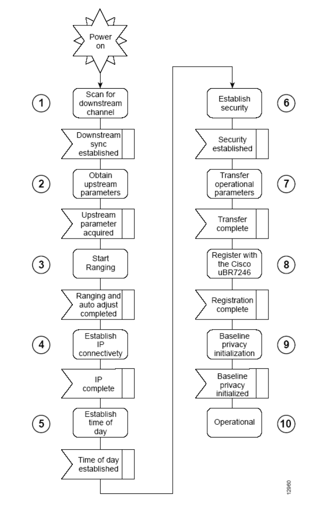
ARCXTEND USER MANUAL – R1.4, ISSUE 4
Copyright 2005 Arcwave, Inc. 74
CABLE MODEM INITIALIZATION
The sequence numbers shown in Figure B-1 are explained in Table B-1, which appears after
the illustration. The cable modem will complete all the steps in this flowchart each time it needs
to reestablish ranging and registration with the CMTS.

ARCXTEND USER MANUAL – R1.4, ISSUE 4
Copyright 2005 Arcwave, Inc. 75
Sequence Event Description
1
Scan for a downstream
channel and
establish synchronization
with the
CMTS.
The cable modem acquires a downstream channel
from the CMTS and saves the last operational
frequency in non-volatile memory. The cable
modem tries to reacquire the saved downstream
channel the next time a request is made.
Note An ideal downstream signal is one that
synchronizes QAM symbol timing, FEC framing,
MPEG packetization, and recognizes downstream
sync MAC layer messages.
2 Obtain upstream channel
parameters.
The cable modem waits for an upstream channel
descriptor (UCD) message from the CMTS. The
UCD provides transmission parameters for the
upstream channel.
3 Start ranging for power
adjustments.
The ranging process adjusts the cable modem’s
transmit power.
4 Establish IP connectivity.
The cable modem sends a DHCP request to
obtain an IP address, which is needed for IP
connectivity. The DHCP response also includes
the name of a file that contains additional
configuration parameters, the TFTP server’s
address, and the Time of Day (TOD) server’s
address.
5 Establish the time of day.
The cable modem accesses the TOD server for
the current date and time, which is used to create
time stamps for logged events (such as those
displayed in the MAC log file).
6 Establish security.
Keys for privacy are exchanged between the cable
modem and the CMTS.
7 Transfer operational
parameters.
After the DHCP and security operations are
successful, the cable modem downloads
operational parameters from a configuration file
stored on the cable company’s TFTP server.
8
Comply with baseline
privacy.
If the software image running on the cable modem
includes baseline privacy, link level encryption
keys are exchanged between the CMTS and the
cable modem.
9
Enter the operational
maintenance state.
As soon as the cable modem has successfully
completed above sequence, it enters operational
maintenance state.
Table B-1 Cable Modem Initialization Steps