Arcwave AX125500 Point To Multipoint Wireless System User Manual Market Requirements
Arcwave, Inc. Point To Multipoint Wireless System Market Requirements
Arcwave >
Contents
- 1. User Manual 1 of 2
- 2. User Manual 2 of 2
User Manual 1 of 2

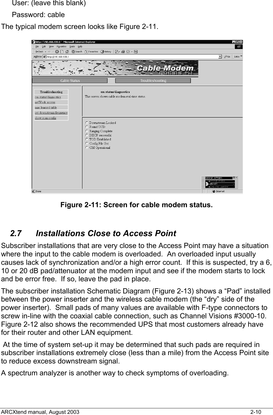
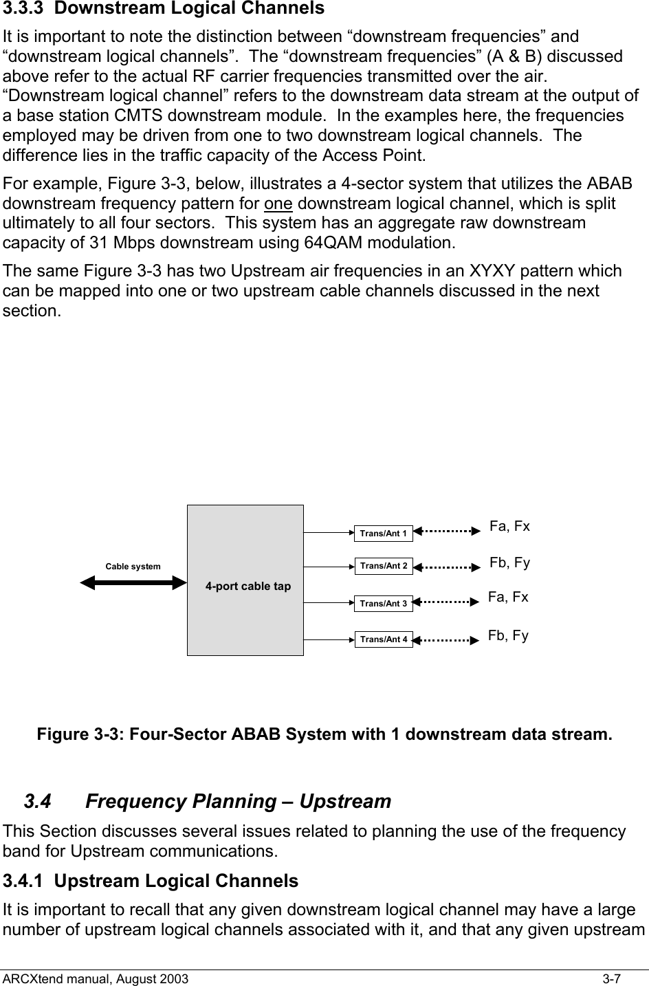
![Power inserterCable to AR3155Modem rear panelModem powerEthernet (LAN) cablePower inserter power cord Figure 2-10: Rear view of typical wireless cable modem. 2.5 Frequency Channel The cable modem will automatically search for the active channels, will go through a handshake with the CMTS, will be told all the parameters it will need to join the wireless network and will be authenticated/authorized to join. 2.6 Modem http Interface The modem status can be determined by the LEDs and by a browser interface. The typical modem LEDs and their use are: Power: ON = power OK Cable: ON = ranged & registered with CMTS, blinking= in process LAN: ON = connected USB: ON = connected [some modems have both USB & LAN connectors] Activity: blinking = data (transmit or receive) The browser interface is available on some modems and contains more information. The typical instructions in the user manual are to follow these steps: Connect a PC to either the modem’s USB or the Ethernet interface Launch the PC’s browser, such as Microsoft’s Internet Explorer Address: http://192.168.100.1 ARCXtend manual, August 2003 2-9](https://usermanual.wiki/Arcwave/AX125500.User-Manual-1-of-2/User-Guide-384476-Page-21.png)