Arcwave AX165500 Point to Multipoint Wireless Internet System User Manual 440CD9AE 25B7 284757
Arcwave, Inc. Point to Multipoint Wireless Internet System 440CD9AE 25B7 284757
Arcwave >
Use rManual

Arcwave, Inc.
100 Albright Way, Suite A
Los Gatos, CA 95032 USA,
Phone: 408-558-2300
www.arcwaveinc.com
© 2006
Arcwave’s ARCXtend HSD Enhanced 5.8
GHz Wireless Plant Extension Solution
Installation Guide
P/N: 920-00009-001 Rev. 1

Installation Guide
2 of 27
About this document
This guide is designed familiarize you with the ARCXtend HSD Enhanced 5.8 GHz WPE
solution. The guide identifies the major components and describes their functions within
the WPE solution. The installation and configuration processes are also discussed in
fundamental terms.
Revision History
Related Documents
The following documents provide additional information about the ARCXtend HSD
WPE solution:
• Arcwave’s ARCSmart User Interface Guide
• Arcwave Enterprise MIB Specification
Feedback
We welcome your feedback on Arcwave documentation. This includes feedback on
structure, content, accuracy, or completeness of our documents, and any other comments
you may have. Please send your comments to marketing@arcwaveinc.com.
Trademarks
Arcwave and the Stylized Arcwave Logo, ARCXtend, ARCXtend HSD, ARCSmart, and
PureBurst are trademarks of Arcwave. Other product/service names are the property of
their owners.
ISSUE # AUTHOR CHECK OUT CHECK IN COMMENTS
1.0 CM MARCH 6, 2006 FOR BETA RELEASE

Installation Guide
3 of 27
Notices
The information in this publication is subject to change without notice. Arcwave shall not
be liable for technical or editorial errors or omissions nor for any damages resulting from
the use of this material.
U.S. Federal Communication Commission (FCC) Notification
This device complies with part 15 of the U. S. FCC Rules and Regulations and which is
subject to the following two conditions: (1) This device may not cause harmful
interference, and (2) This device must accept any interference received, including
interference that may cause undesired operation.
This equipment has been tested and found to comply with the limits for a Class A digital
device, pursuant to Part 15 of the U.S. FCC Rules. These limits are designed to provide
reasonable protection against harmful interference in a residential installation. This
equipment generates, uses, and can radiate radio-frequency energy and, if not installed
and used in accordance with these instructions, may cause harmful interference to radio
communications. If this equipment does cause harmful interference to radio or television
reception, which can be determined by turning the equipment on and off, the user is
encouraged to correct the interference by one or more of the following measures:
Increase the separation between the affected equipment and the unit;
• Connect the affected equipment to a power outlet on a different circuit from that
which the receiver is connected to;
• Consult the dealer and/or experienced radio/TV technician for help.
Part 15, Section 15.21 Warning
Changes or modifications not expressly approved by Arcwave, Inc. could void the user's
authority to operate the equipment. FCC IDs Numbers are listed below:
FCC Identifier: Pending
RF Safety Warning
To ensure compliance with FCC recommended General Population/Uncontrolled
exposure limits the ARCXtend Hub and CPE must be installed at a minimum of one foot
from areas frequented by the general population.

Installation Guide
4 of 27
To ensure compliance with FCC recommended Occupational/Controlled exposure limits,
field engineers and technicians should maintain a minimum working distance of six
inches, as measured from the front of the Hub or CPE to the front of their bodies. For
working distance inside six inches, RF exposure should be limited to an average of 30
minutes at a time. All Arcwave equipment, however, has been designed to allow
installation and maintenance at a range well within FCC RF exposure levels.
DOCSIS Network Considerations
Embedded Cable Modem Operation
The ARCXtend Hub contains an embedded cable modem for remote management of the
hub via the DOCSIS network, obtaining the DOCSIS operating parameters needed to
program the hub and monitoring input RF signal level and quality. The embedded cable
modem is identical in operation to a customer cable modem and requires Internet
Protocol (IP) connectivity.
Setup
Prior to deployment of the ARCXtend solution, the embedded cable mode configuration
file and firmware must be loaded on the TFTP server. The configuration and firmware
files are included on the documentation CD shipped with each hub and can be
downloaded from the Support Extranet, http://www.arcwaveinc.com/support.html.
The configuration file provided by Arcwave contains the necessary modem specific
information required to do firmware downloads.
Before an individual hub can be assigned an IP address its MAC address must be
provisioned in the DHCP server. If the MAC address is not provisioned prior to
deployment, most likely the embedded cable modem will receive a default configuration
with Network Access set to “disable”. The Ethernet MAC address of the embedded cable
modem is located on a label on the back of each hub.
Load Balancing Groups
Currently, the ARCXtend solution does not support upstream shared spectrum (aka load
balancing) groups where the cable modem(s) can be moved from one upstream frequency
to another based on plant conditions. Both the customer cable modem and the cable
modem located inside the hub must be explicitly excluded from this feature. This is
usually accomplished by putting the MAC addresses of both in an exclusion list kept by
the CMTS.

Installation Guide
5 of 27
Downstream and Upstream Frequency (Channel) Configuration
The customer cable modem should never be configured to acquire a specific downstream
frequency as there is not a one-to-one correlation between the cable network downstream
frequency and the downstream frequency output by the ARCXtend CPE. The
downstream frequency output by the ARCXtend CPE is a purely a function of the
downstream wireless channel selected.
When multiple downstream and/or upstream frequencies (channels) are used on the cable
network, the “AutoFrequencySet” feature must be disabled and the “CATV EIA Input
Channel” and the “Upstream Frequency” must be set manually. Alternatively, the correct
downstream and upstream frequency can be included in the embedded cable modem
configuration file in which case the “AutoFrequencySet” feature can be used.
TCP/IP Port Filtering
TCP/IP port filtering is the practice of selectively enabling or disabling Transmission
Control Protocol (TCP) ports and User Datagram Protocol (UDP) ports on computers or
network devices. The following ports must be open for SNMP, HTTP, and TFTP
applications to be performed on the Hub:
• Port 161/162 for SNMP
• Port 80 for HTTP
• Port 69 for TFTP
Installation Guide
6 of 27
Introduction
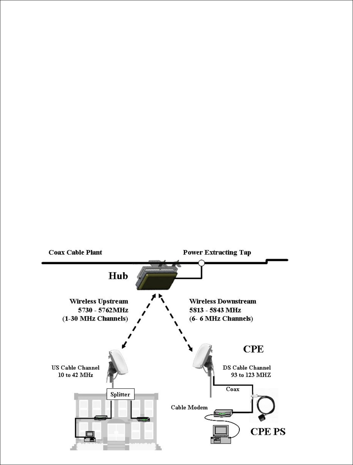
The ARCXtend HSD Enhanced 5.8 GHz WPE solution is a layer one wireless bridge
device that provides wireless connectivity between a coaxial cable plant and one or more
customer sites. The WPE solution operates in the 5,725 MHz to 5,850 MHz frequency
band and supports the transparent delivery of one digitally modulated 6 MHz cable
downstream channel and one, up to 6.4 MHz, upstream channel transporting the
following services:
• DOCSIS 1.0/1.1/2.0 high speed data, IP Video or Voice over IP (VoIP) signals
• MPEG video streams
• Other digitally modulated services such as Ethernet or TDM over HFC.
The solution consists of these major components:
• Strand mount hub (Hub)
• Customer premise equipment devices (CPE)
• CPE power supply (PS)
Installation Guide
7 of 27
The hub connects directly to the coaxial portion of cable plant using a standard power
extracting tap and is line powered over coax using 60 or 90 VAC. The CPE is installed at
the customer site, connects to a standard cable modem, and is powered over the coax
cable using a wall mounted AC adaptor and DC to coax power inserter.
In the downstream direction the hub receives a digitally modulated channel in the range
between 90 and 860 MHz from the cable plant and up converts it to one of the six
available wireless channels in the upper part of the 5.8 GHz frequency band. The CPE
receives the wireless signal and down converts it to a channel in the range 93 to 123 MHz
for reception by a cable modem.
In the upstream direction the CPE transmits the entire 10 to 42 MHZ frequency range in
the lower part of the 5.8 GHz frequency band. The hub receives the wireless channel,
tunes to the frequency carrying the active upstream channel, and down converts it back to
the original frequency in the 10 to 42 MHz range. With Arcwave’s PureBurst upstream
noise suppression technology the hub’s upstream transmitter is only “opened” when a
wirelessly attached cable modem is sending data. The digital signals are never
demodulated/modulated ensuring transparent service and equipment support.
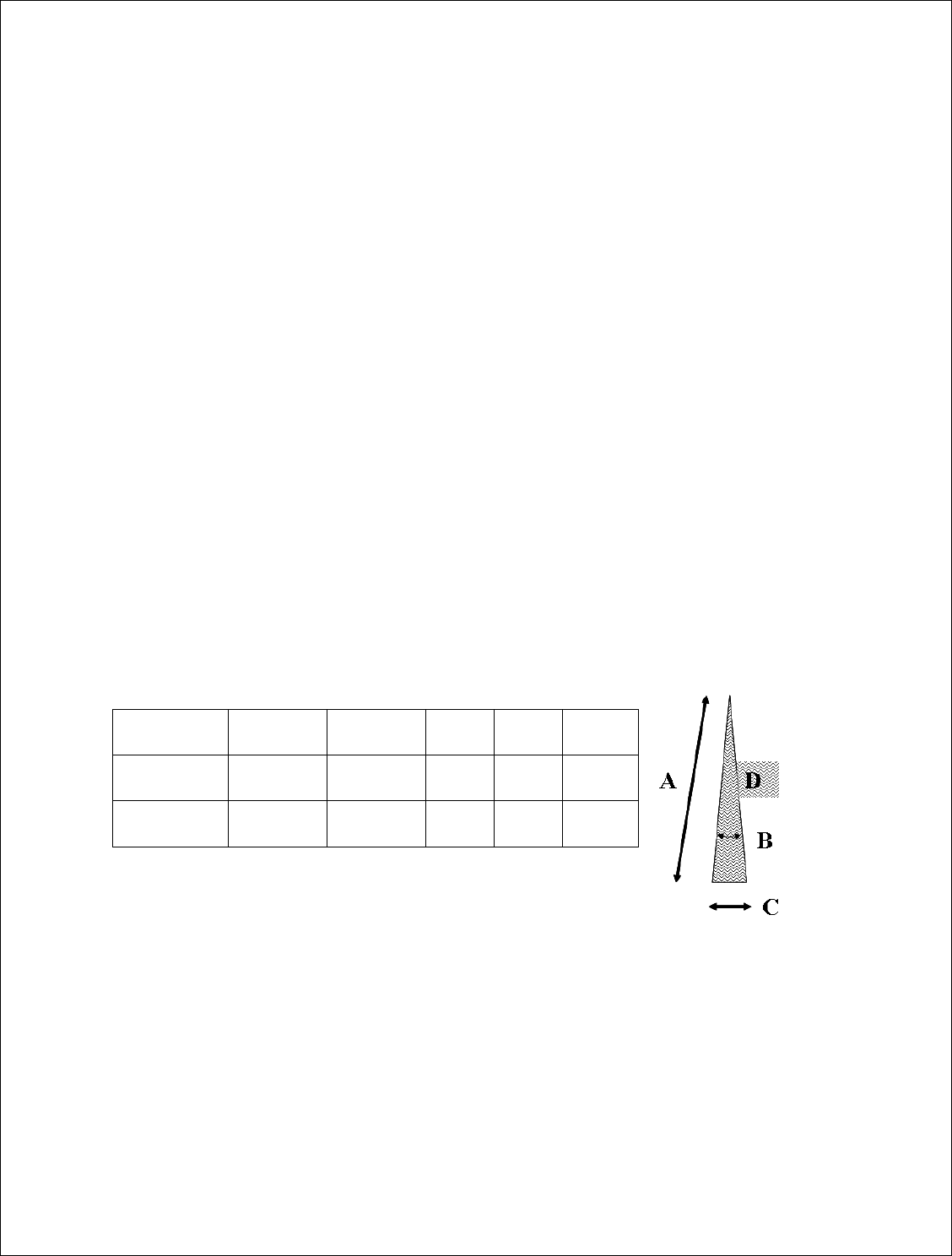
Coverage and Range
The ARCXtend Enhanced 5.8 GHz WPE solution hubs are factory configured for
extended range or extended coverage applications. The range and coverage profile for
both solutions are detailed in the following table and illustration.
Hub Type DS
Modulation
Range (A)
(mi)
Arc (B)
(deg)
Arc (C)
(mi)
Area (D)
( sq-mi)
AX1655-ER 64 QAM
256 QAM
2
¾
20° 0.7
0.3
0.7
0.1
AX1655-EC 64 QAM
256 QAM
2
½
60° 2.1
0.5
2.1
0.1
Installation Guide
8 of 27
The Hub
The Hub is a self-contained weather-protected, strand mountable unit providing a bi-
directional wireless connection between a cable plant and a cable modem. The Hub
includes an integrated transceiver, patch antenna, embedded cable modem, hub controller
and Arcwave’s ARCSmart intelligent management software.
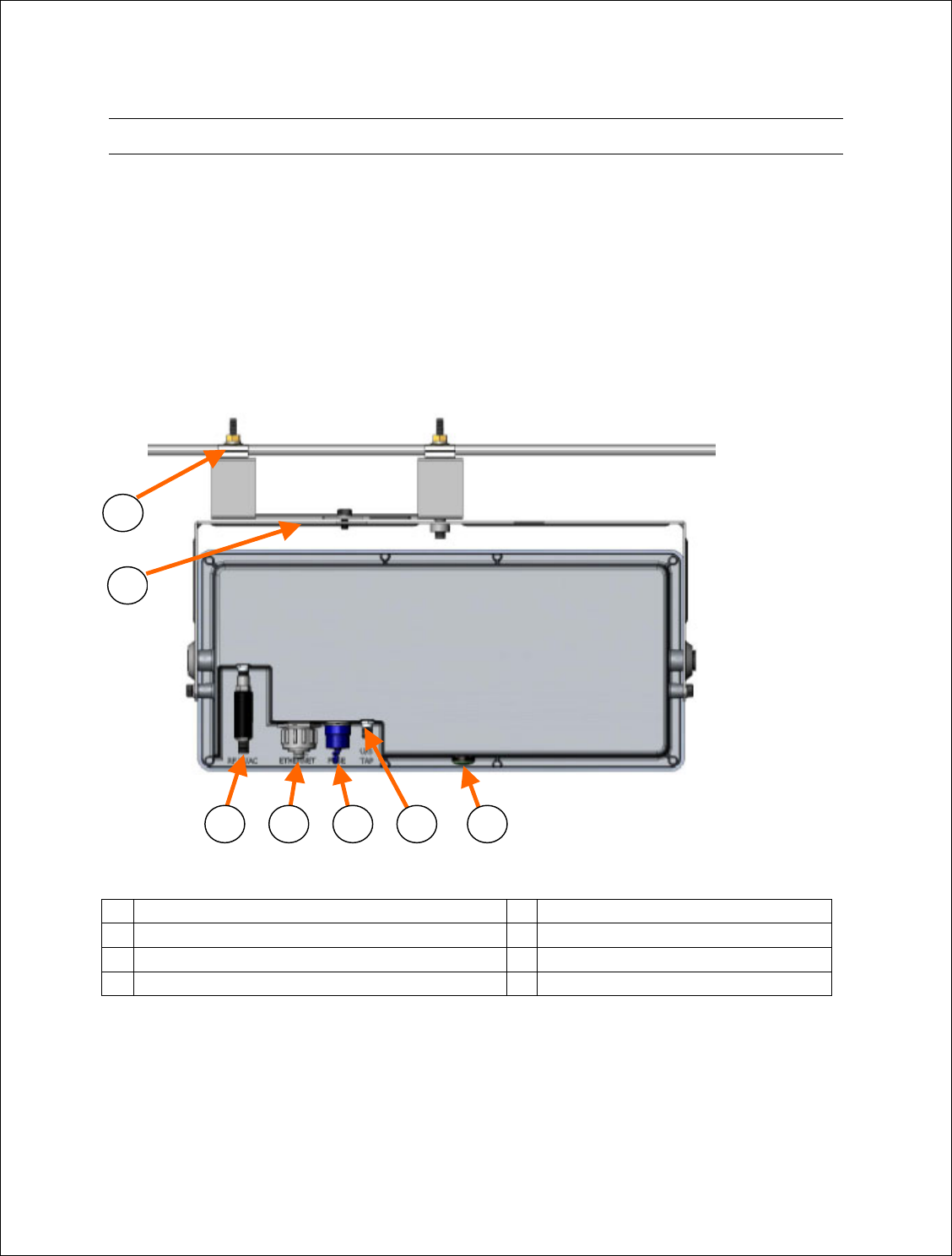
Interfaces
The following illustration shows the rear of the Hub and identifies the interfaces.
1 Strand Mounting Clamps 5 Fuse
2 Alignment Brackets 6 U/S Tap
3 RF W/ AC 7 LED
4 Ethernet
Strand Mounting Clamps
Cable industry standard clamps for mounting the hub to the strand cable.
2
3 4 5 6 7
1

Installation Guide
9 of 27
Alignment Brackets
Mechanically adjustable horizontal and vertical hub alignment brackets for aligning the
hub’s integrated antenna to the desired coverage area. A 7/16” wrench is the only tool
required for mounting and aligning the hub.
RF W/AC
An AC surge protected SCTE compliant female F-type connector for the RF and AC
power connection to the cable network. The Hub requires an input RF power level at the
port of between 0 dBmV and +30 dBmV with a minimum modulation error ratio (MER)
of 35 dB for 256 QAM and 31 dB for 64 QAM. The input line power must be between 50
VAC and 110 VAC with a line frequency from 50 Hz through 60 Hz.
ETHERNET
A weather-proof RJ-45 connector for connecting a lap top PC for hub configuration and
monitoring during installation or troubleshooting and for powering hub using 24 VDC
power over Ethernet (PoE) per the table below:
Pin Function US modern T-568A
1 Ethernet Tx+ green-white
2 Ethernet Tx- green
3 Ethernet Rx+ orange-white
4 PoE - lower voltage (+) blue
5 PoE - lower voltage (+) blue -white
6 Ethernet Rx- orange
7 PoE - higher voltage (-) brown-white
8 PoE - higher voltage (-) brown
FUSE
An SCTE compliant replaceable 1 ampere fuse providing over current protection for the
RF W/AC port.
U/S Tap
An SCTE compliant female F-type connector providing a -20 dB tap for monitoring the
upstream channel.

Installation Guide
10 of 27
LED
Green/amber weather proof status LED indicating:
Amber Solid Power ON
Amber Blinking Embedded cable modem has Downstream Lock
Green Blinking Embedded cable modem has Upstream Lock
Green Solid Embedded cable modem is Operational
Ground Lug
The ground lug terminal is for bonding the hub chassis to the strand wire.
MAC address
Each hub model has a unique MAC address as indicated on the label located on the rear
of the unit. This MAC addressed must be provisioned in the cable IP network DHCP
server in order for the hub’s internal cable modem to be assigned an IP address on power
up.
Hub Configurations
The hub is available in extended coverage or extended range configurations as described
below:
• The AX1655-EC extended coverage hub hangs from the cable strand and
provides 60 degrees of coverage and has a maximum range of up to ½ mile.
• The AX1655-ER extended range hub hangs from the cable strand and provides 20
degrees of coverage and has a maximum range of ¾ mile.
• The AX1655-SMA pole mount adaptor kit allows the hub to be mounting on
towers or buildings using off-the-shelf 1-1/4 to 2-3/8 O.D. mast mount hardware.
Integrated Antennas
The AX1655-ER extended range and AX1655-EC extended coverage Hub models
include the following antennas:
Style -3 dB Horiz.
Beamwidth
-3 dB Vert.
Beamwidth
Transmit
Gain
Receive Gain
AX1655-ER Flat Panel 20° 18° 18 dBi 16 dBi
AX1655-EC Flat Panel 60° 18° 14 dBi 14 dBi
Installation Guide
11 of 27
The CPE
The CPE is small footprint weatherproof radome that can be easily mounted on a rooftop
or side of a building to provide connectivity to the wireless network. It contains an
integrated transceiver and a narrow-beam antenna that can be easily aligned to receive the
signal from a Network Hub. The CPE is roughly one foot square and supports low cost
installation using the same hardware and skills as a small satellite dish.
CPE Configuration
The CPE comes in one configuration, model number AX3655-VM-10, which includes a
10° receive beamwidth high gain antenna.
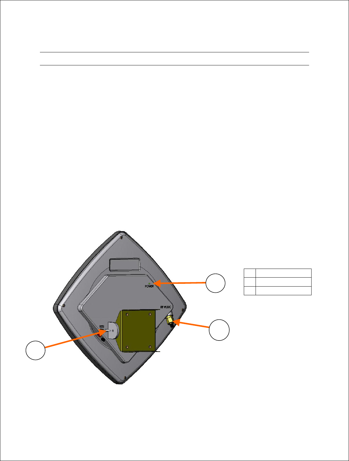
Interfaces
The following illustration shows the rear of the Hub and identifies its interfaces.
1 RF W/DC
2 POWER
3 RSSI (VDC)
2
3
1
Installation Guide
12 of 27
RF W/DC
An SCTE compliant F-type connector provides the RF connection to the cable modem
and for powering the CPE. The CPE operates on 18 Vdc nominal which is provided by
the Arcwave supplied wall mounted 120 VAC CPE adaptor and DC power inserter,
model number AX3655-PS-18. The DC inserter must be located within 300 feet of the
CPE to ensure a minimum input voltage of 12 VDC at the RF W/DC port. The CPE can
accept an input RF signal between 10 and +30 dBmV from the cable modem.
POWER
The Power Led indicates the CPE is power on.
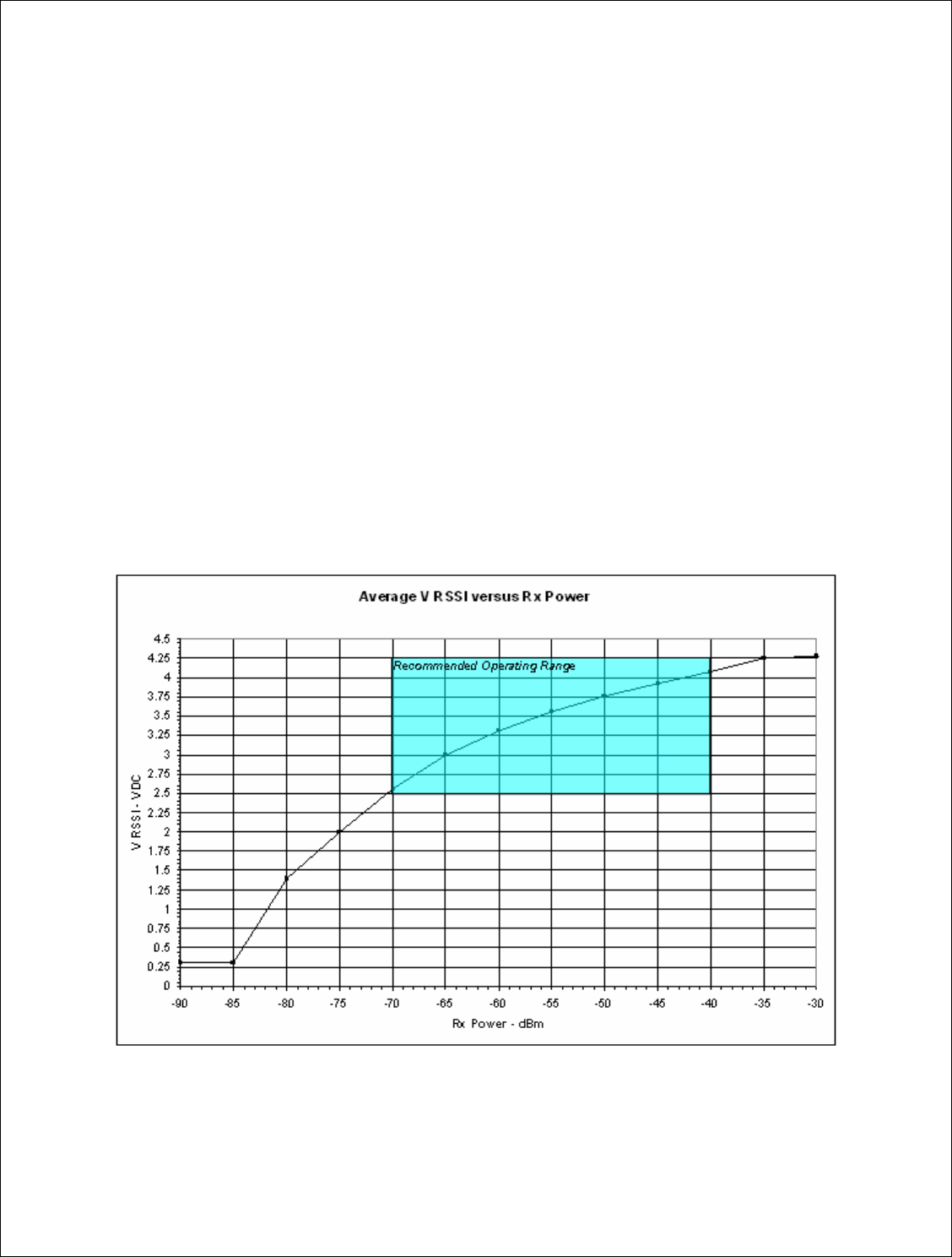
RSSI (VDC)
The RSSI banana jacks produce a DC voltage proportional to the wireless received signal
level. The recommended operating range is between 3 and 4.25 VDC which corresponds
to a receive signal level of between -70 and -40 dBm as shown in the graph below.

Installation Guide
13 of 27
Deploying the ARCXtend Equipment
Personnel installing the equipment must be familiar with basic cable drop, cable modem
and ARCXtend WPE solution installation and troubleshooting techniques.
Equipment, materials and tools
The following equipment, materials and tools are required for installation:
Equipment Source Use
Digital Cable TV Installation
Meter
Sunrise Telecom Hukk CM500 or
equivalent
Hub installation & link commissioning
7/16” wrench Multiple Hub and CPE installation
Spotting Scope or Binoculars Multiple Hub site selection
Bucket Truck Multiple Hub Installation
Walkie Talkies or Cell
phones
Multiple Communicate between Hub and CPE sites
Laptop Computer w/ Serial
& Ethernet Ports
Multiple Hub monitoring and configuration
Material Source Use
Hub Arcwave Wirless interface to cable network on plant
side
CPE
Arcwave Wirless interface to cable network on
customer side
DC Inserter and Adaptor Arcwave
Powering CPE
Power Passing/Extracting
Tap
Multiple Provides RF signal and power for network
hub
CPE Mounting Hardware Telewire Mounting CPE at the installation site
RG-6 coaxial cable and male
“F” type connectors
Multiple Connecting the network hub to the power
passing tap
Connecting the CPE to the cable modem
Ground device Multiple Grounding the CPE installation
Surge Protector Array Solutions Model 310 Protects the cable modem and susbcriber
equipment from damage due to a lightning
strike.
Installation Guide
14 of 27
Installation Overview
The installation process involves major four steps:
• Wireless link planning
• Installing the hub
• Installing and aligning the CPE(s)
• Installing the customer cable modem
Wireless link planning
Wireless link planning is essential to the success of WPE installation and is highly
recommended before attempting to install the equipment. Refer to Arcwave’s Wireless
Plant Extension Application and Deployment Training presentation and Wireless Link
Planning Tool located on Arcwave’s support extranet or contact Arcwave customer
support for guidance on how to complete this step.
An acceptable wireless link is one within the working range of Hub and with line of sight
clearance to the customer sites.
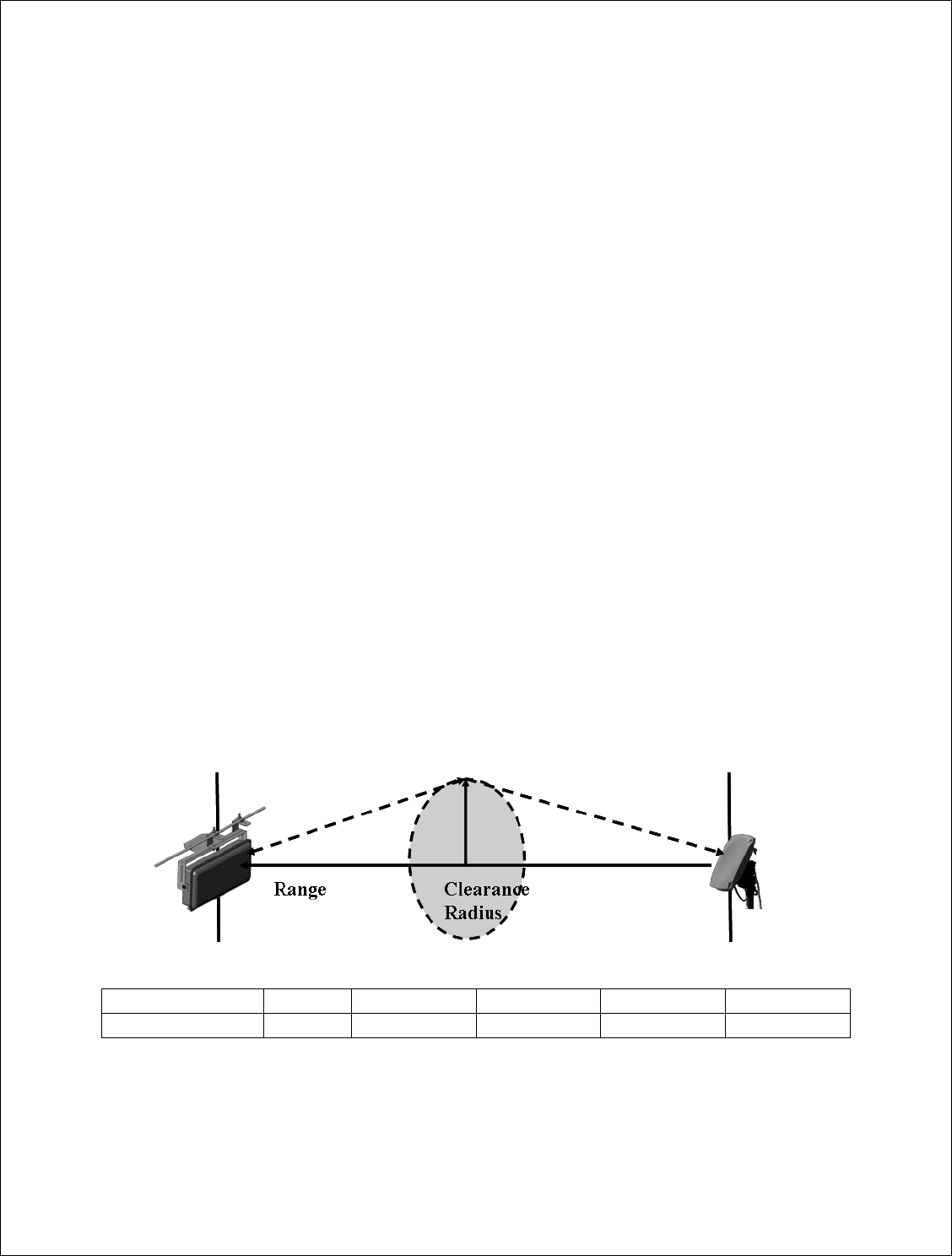
Line of sight is defined as a path between the hub and CPE that is free of obstructions in
the Fresnel zone. Obstructions can be trees, buildings, street signs, etc. An accepted rule
of thumb is that LOS conditions exist when there are no physical obstructions within 60%
of the Fresnel zone (obstruction free zone). The Fresnel Zone clearance is determined by
the distance between the Hub and CPE as shown in the following illustration and table.
Range 500 ft 1000 ft ½ mile 1 mile 2 miles
Clearance Radius 3 ft 4 ft 6 ft 9 ft 12 ft
Installation Guide
15 of 27
Installing the hub
This section provides instructions on how to install the hub on a cable strand with AC
powered provided over the coaxial cable. The hub can also be installed on a rooftop, mast
or tower using the AX1655-SMA pole mount adaptor kit. It can be powered using power
over Ethernet per the wiring diagram provided in the previous section.
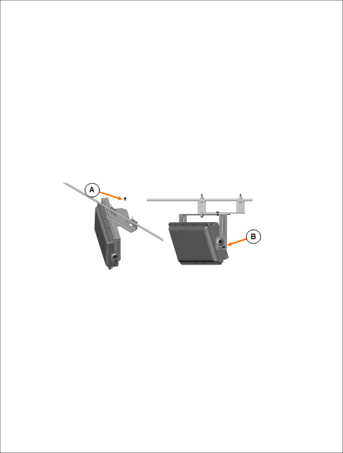
Aligning the hub
Attach the bracket to the messenger strand with the two hanger bolts. Position the hub’s
antenna (located behind the radome) to the azimuth and elevation determined by the
wireless link planning. The azimuth position is adjusted by placing bolt A in the
appropriate location on the azimuth alignment bracket and the elevation is adjusted by
loosening bolts B and rotating the hub face up or down and tightening bolts B at both
ends.
Connecting the hub
Install a CATV power passing/extracting tap suitable for your plant and
the hub powering requirements. The hub draws 24 watts maximum and
can accept 50 Vac and 110 Vac.
Verify that the input downstream RF signal level is between 0 dBmV and
+30 dBmV.
Verify that the modulation error ratio (MER) of the downstream signal is a
minimum MER of 35 dB for 256 QAM and 31 dB for 64 QAM
operations.
Connect the hub to the cable plant using a setup suitable for the cable plant
and hub powering requirements.

Installation Guide
16 of 27
Verify via the hub that hub has power and the embedded cable modem has
achieved operational status.
Provisioning the Link
Link provisioning is accomplished using via the ARCSmart HTTP web browser interface
or via the ARCNet element management system. The parameter names and assignments
are the same for both interfaces. Detailed information is available for both tools in their
respective user and installation guides located on the Arcwave Support Extranet,
http://www.arcwaveinc.com/support.html. This section describes the ARCSmart GUI and
shows how to perform a typical configuration.
To launch ARCSmart:
• Connect a computer to the hub’s RJ-45 Ethernet port.
• Open your Internet browser. You must use Microsoft Internet Explorer version
5.x or later.
• Enter the default IP address of the Hub (192.168.100.1) into the address bar of
your browser and press the enter key on your keyboard. An Enter Network
Password window appears.
• Enter the case sensitive username admin and press the Tab key to advance to the
password field.
• Enter the case sensitive password arcwave and press Enter.
Note the username and password can be changed using the Maintenance screen
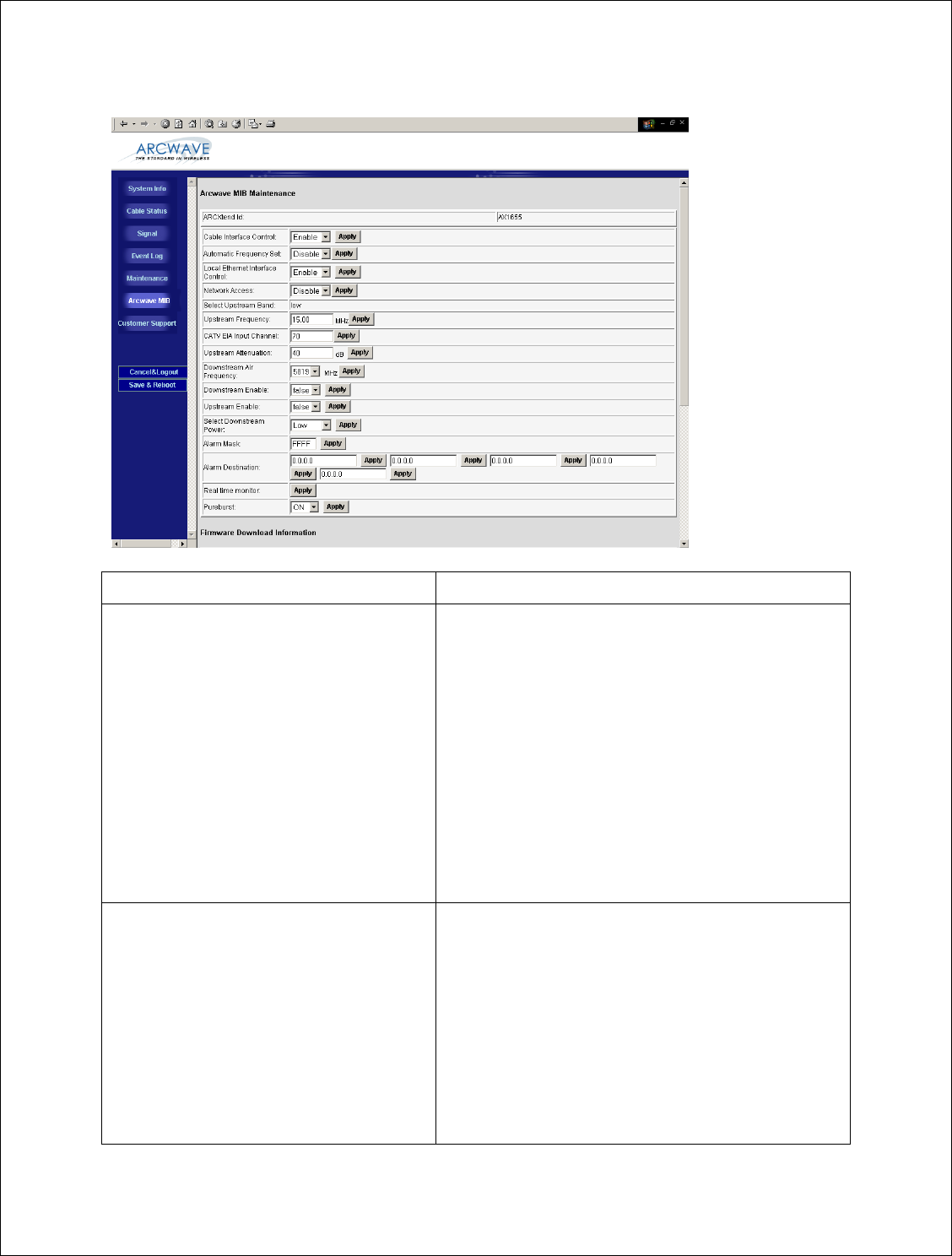
• Click on Arcwave MIB in the left menu bar. This will launch the Hub
configuration screen shown below.
• Enter the configuration settings determined in the wireless link planning process:
Installation Guide
17 of 27
PARAMETER DESCRIPTION
Cable Interface Control Choose “Enable” to turn-on the RF interface of the
ECM and “Disable” to turn it off. This parameter is
useful when the Hub is used for a non-DOCSIS
application, such as the wireless transport of a digital
video or CBR (constant bit rate) voice signal, and
there is no DOCSIS channel on the cable plant.
Selecting “Disable” will prevent the ECM from
continually scanning for a downstream channel,
when none is present. The default setting is
“Enable”.
When Cable Interface Control is set to “Disable”,
Network Access is set to “Disable” and Upstream
Attenuation can not be set to “99”, automatic mode.
Auto Frequency Set Choose “ENABLE” to have ARCSmart
automatically program the Hub CATV EIA Input
Channel and Upstream Frequency parameters with
the same values used by the ECM. When set to
“ENABLE” these values will change whenever the
values are changed at the ECM. This setting is used
for plug-n-play installation of the Hub. Choose
“Disable” when these parameters will be set
manually to values different than those used by the
ECM. In this mode the values entered will persist
re
g
ardless of the values used b
y
the ECM and across

Installation Guide
18 of 27
PARAMETER DESCRIPTION
a Hub power outage or reboot. This mode is useful
when the Hub transmits a non-DOCSIS channel,
such as digital video or CBR voice.
The default setting is “Enable”. Note: “Cable
Interface Control” must be set to “Enable” in order
for this element to be set to “Enable”.
Local Ethernet Interface Control Choose “Enable” to allow local connection to the
Hub via the RJ-45 connector. Choose “Disable” to
disable the RJ-45 connection and prevent anyone
from connecting locally to the Hub.
When Local Ethernet Interface is set to “Disable”,
Network Access is also set to “Disable”.
Network Access Choose “Enable” to allow a locally connecting
computer to obtain an IP address, via DHCP, from
the head end server and to access the cable IP
network.
Choose “Disable” to prevent a locally connected
computer from accessing the cable IP network. The
locally connected computer will be assigned a
default IP address in the 192.168.100.0/24 network.
Select Upstream Band Not used on the AX1655.
Upstream Frequency Displays the frequency of the upstream channel that
is being received by the Hub.
CATV EIA Input Channel Displays the EIA standard channel number of the
D/S channel that is being received by the hub.
Upstream Attenuation Choose the amount of attenuation (in dB) in the
upstream receive path of the Hub.
If “99” is entered, ARCSmart will automatically set
the attenuation based on the upstream channel
transmit power out of the ECM. If a number in the
valid range from 0 to 64 is entered, the attenuation is
set to that value.
This parameter is used to increase or decrease the
upstream channel transmit power of a cable modem
connected wirelessly to a Hub. Increasing the
attenuation will cause the CMTS to increase the
cable modem’s upstream channel transmit power.
Decreasing the attenuation will cause the CMTS to
decrease the cable modem’s upstream channel
transmit power. The change in the attenuation and
the change in the upstream channel transmit power,
while loosely related, is not one to one.

Installation Guide
19 of 27
PARAMETER DESCRIPTION
Note: “Cable Interface Control” must be set to
“Enable” in order for this element to be set to “99” .
Downstream Air Frequency Choose the downstream wireless carrier frequency.
Valid settings for AX1655 model Hubs are: 5813,
5819, 5825, 5831, 5837, and 5843 (in MHz).
The downstream channel frequency out of the CPE
is the Downstream Air Frequency minus 5720 MHz.
Downstream Enable Choose “TRUE” to turn on the downstream wireless
transmitter and “FALSE” to turn it off. The default
setting is “TRUE”.
Upstream Enable Choose “TRUE” to turn on the upstream wireless
receiver and “FALSE” to turn it off. The default
setting is “TRUE”.
Select Downstream Power Choose the downstream wireless transmitter power
setting: High, Medium or Test
Alarm Mask The alarm mask corresponds to the hex number,
which when translated into a binary number gives an
8 digit number. The position of a digit ‘1’ in the
field will enable the corresponding alarm and a digit
‘0’ would disable the corresponding alarm. All 0’s
mask all alarms, all F’s passes all alarms. Individual
alarms are respresented as follows:
Bit 0: 1 = System Lock Lost
Bit 1: 1 = Hub Dead
Bit 2: 1 = Input voltage outside of tolerance
Bit 3: 1 = The Unit is operating near its maximum
operating temperature.
Bit 4: 1 = DCE Unlocked or Error
Bit 5: 1 = Upstream (Receiver) Unlocked or Error
Bit 6: 1 = Downstream (Transmitter) Unlocked or
Error
Bit 7: 1 = Local modification notification
Example: If the user wanted alarms “System Lock
Lost, Input voltage outside of tolerance, DCE
Unlocked or Error and Local Parameter
Modification Notification” turned on and the rest
turned off, he would have to set the alarm mask to
0095 (Hex), which corresponds to 10010101
(Binary). The bits that correspond to the alarms we
want turned on have been set to 1 and the rest have
been set to 0.

Installation Guide
20 of 27
PARAMETER DESCRIPTION
Alarm Destination Enter up to (5) IP addresses where SNMP traps are
to be routed to by the Hub.
Real time monitor Click on the “Apply” button to refresh the Real
Time Monitor display.
PureBurst Choose “On” to enable PureBurst and “Off” to
disable PureBurst. When no traffic is present on the
upstream cable interface, PureBurst mutes the
interface preventing the introduction of ingress noise
into the cable network. Default setting is “On”.
Installation Guide
21 of 27
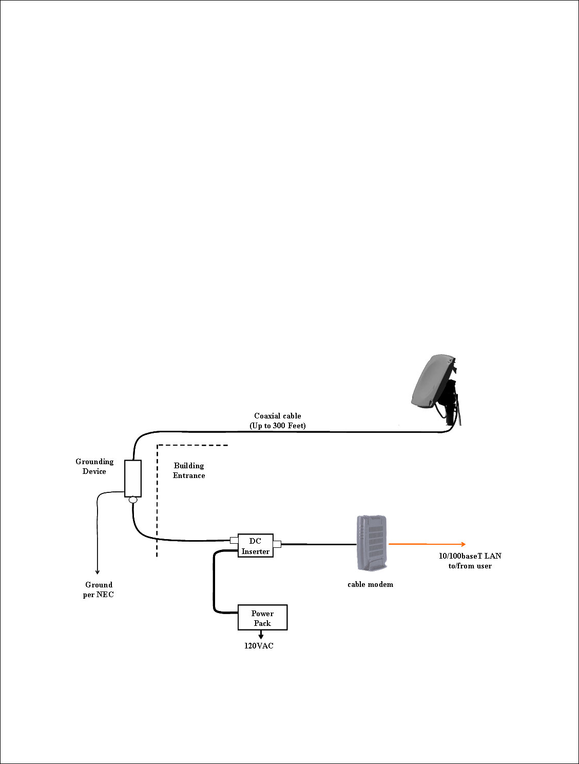
Installing the CPE
Install the mounting hardware (e.g. non-penetrating roof mount, eaves mount) and
coaxial cable per the manufacturer’s recommended procedures and in accordance with
the National Electric Code and local ordinances.
Loosen the (4) mounting bolts and slide the CPE on the mounting pipe.
Visually align the CPE in the direction of the Hub and snug the mounting
bolts to hold the CPE in place.
Install the coaxial cable and ground connections as shown in the
illustration below.
Waterproof the coax connections using a suitable method such as taping
with Coax-Seal or Scotch #88.
Install the power adaptor and DC inserter as shown in the illustration
below.

Installation Guide
22 of 27
Please note the following during installation:
• The CPE accommodates a mounting pipe with of 1-1/4” to 2-3/8” in diameter and
the CPE and mounting pipe require a minimum of 12 inches clearance on all sides
for optimal performance.
• The CPE should be located as close to the edge of the building nearest the hub as
possible. When the CPE is mounted towards the middle or back of the building,
the incoming wireless signal may be reflected by the rooftop impairing the
performance of the link. The CPE must be placed high enough on the rooftop to
provide the required Fresnel zone clearance).
• The adaptor must be located within 300 feet of the CPE to ensure a minimum
input voltage of 12 VDC at the CPE.
• The CPE must be mounted at least 2 feet below the highest point at the site to
minimize the likelihood of lightning strikes. The location should be properly
grounded for lightning protection to all applicable national (National Electric
Code, sections 820-33 and 820-40) and local codes.
• An SCTE compliant surge protector is required between the CPE and customer
cable modem.
• Be sure to leave sufficient slack for final CPE alignment and ensure that the cable
runs directly downward from the connector to avoid water running down the cable
and into the F connector.
Align the CPE
Position the CPE’s antenna (located behind the radome) to the azimuth and elevation
determined in the wireless link planning. The elevation is adjusted using the elevation
alignment bolts and the azimuth is adjusted using the mounting bolts.
Connect a voltmeter to the RSSI jacks on the back of the CPE.
Pan the CPE from side to side (horizontally) and tilt it up and down
(vertically) while observing the RSSI DC voltage on the meter. The goal is
to obtain the maximum reading within the recommended operating range
of between 3 and 4.25 volts which corresponds to a receive signal level of
between -70 and -40 dBm.
Tighten the elevation and mounting bolts.

Installation Guide
23 of 27
Verify CPE output signal at input to cable modem
Using a spectrum analyzer or digital signal level meter, verify that the downstream
channel power level is within the desired range for the cable modem. If it is not correct,
troubleshoot per the table below:
Power level is too high Power level is too low Signal is not present
Install one or more 10 dB
(AX3155-ECF-10) or 20
dB (Ax3155-ECF-20) low
pass attenuators between
the power inserter and the
cable modem.
If more than 30 dB of
attenuation is required,
reduce the hub’s
downstream power setting.
Verify the CPE alignment.
Verify the hub’s
downstream power setting.
Reduce/remove the low pass
attenuation.
Reduce the cable and RF
hardware loss between CPE
and cable modem or add bi-
directional amplification.
Verify that the range and
Fresnel Zone clearance are
within specifications.
Verity that the CPE Adaptor
and DC inserter are
installed properly
Verify the DC power level
at the input to CPE.
Verify the coaxial cable
connections.
Verify that the range and
Fresnel Zone clearance are
within specifications.
Verify cable modem output signal at CPE
Using a spectrum analyzer or digital signal level meter, verify that the channel power into
the CPE is between +10 and +30dBmV for optimal performance. If it is too high or too
low, adjust the Upstream Attenuation setting on the Arcwave MIB screen a
proportionate amount.

Installation Guide
24 of 27
Cable Modem Installation
Connect the cable modem the TV port of the DC inserter as shown in the prior
illustration.
Set the upstream signal level
Using the cable modem’s diagnostic interface, check the upstream signal (US) level is
within the desired operating range.
Power level is too high Power level is too low
Decrease the “Upstream Attenuation” setting
in the Arcwave MIB Maintenance page of
the user interface by an amount equal to the
desired decrease in the upstream power level.
i.e. if the US transmit power is 50 dBmV and
it should be 45 dBmV then reduced the
Upstream Attenuation setting by 50 dBmV
minus 45 dBmV, or 5 dBmV.
Reduce the cable and RF hardware loss
between CPE and cable modem or add
amplification.
Redo the CPE alignment process
Verify the wireless range and LOS path
between Hub and CPE are within specified
limits.
Increase the “Upstream Attenuation” in
the Arcwave MIB Maintenance page of
the user interface setting by an amount
equal to the desired increase in the
upstream power level. i.e. if the US
transmit power is 40 dBmV and it should
be 45 dBmV then increase the Upstream
Attenuation setting by 50 dBmV minus
45 dBmV, or 5 dBmV.
If the cable modem doesn’t register with the network
If the cable modem does not register with the network, troubleshoot as follows:
Problem Solution
Does not detect and lock on to the DS
channel
Verify that the MER of the downstream RF
channel at the output of the CPE is within
specified limits:
MER should equal to or greater than 28 dB
for 64 QAM, and equal to or greater than
31 dB for 256 QAM. If it is not,
p
erfor
m

Installation Guide
25 of 27
Problem Solution
the following checks:
• Verify that the “Select Downstream
Power” setting is correct for the
downstream modulation and
wireless range.
• Change “Downstream Air
Frequency” to a different channel
to rule out interference.
• Verify that the range and Fresnel
Zone clearance are within
specifications.
Does not detect and lock on to the US
channel
Using the customer cable modem’s
diagnostic interface, verify that the cable
modem is sending on the correct upstream
RF channel:
If it is sending on the correct RF channel
but can’t lock on, reduce the Upstream
Attenuation setting at the Hub.
If it does not send on the correct channel,
and Cable Interface Control and Automatic
Frequency Set are enabled, verify that the
Hub ECM and the subscriber cable modem
are assigned to the same upstream
frequency and that both are excluded from
an upstream load balancing group.
If it does not send on the correct channel,
go to the Hub and verify the following:
Using the -U/S Tap port on the Hub, verify
the Hub is receiving a wireless signal from
the CPE.
• If there is a signal present, adjust
the “Upstream Attenuation” setting
at Hub until the cable modem locks
on the US channel.
•If there is not a si
g
na
l
,
v
erif
y
the

Installation Guide
26 of 27
Problem Solution
there is RF output from the
customer cable modem. If there is
no RF output replace the cable
modem. If there is an RF output
replace the CPE.
Cable Modem does not receive an IP
address
Perform normal cable modem installation
troubleshooting procedures.
Cable modem does not receive time of day
(ToD)
Perform normal cable modem installation
troubleshooting.
Cable modem does not receive the
configuration file
Perform normal cable modem installation
troubleshooting.
Cable modem initializes, receives the
configuration file, and then reboots
Verify that the configuration file being
downloaded to the cable modem does not
contain downstream channel information.
The downstream RF channel frequency
being delivered by the CPE to the Cable
Modem is different than what is received at
the Hub.

Installation Guide
27 of 27
Link Verification
Verify the ARCXtend wireless link
• Downstream path measurements
DS
Modulation
Expected Performance Troubleshooting
64 QAM 28 dB MER
10-8 BER, post-error
correction
256 QAM 31 dB MER
10-8 BER, post-error
correction
Inspect the constellation to
determine the type of impairment
affecting the signal and
troubleshoot accordingly.
Verify the plant MER is greater
than required for the downstream
modulation
• Upstream path measurements
Parameter Expected Performance Troubleshooting
CM output
Power
+40-50 dBmV typical
55 dBmV max
+30 dBmV min
If the cable modem output power is
too high, reduce the amount of loss
in the drop to allow for margin or
reduce the “Upstream Attenuation”
setting.
If cable modem output power is too
low, increase the hub’s “Upstream
Attenuation” setting.
BER 10-8 BER, post-error
correction for QPSK and 16
QAM
To test BER on the return
path, the analyzer can ping the
CMTS with a packet of
known data. The ping
command will return the
packet to the analyzer from
the CMTS on the downstream
path.
Verify the return or upstream path
of the wireless link at the U/S Tap
on the hub with PureBurst disabled
and with a spectrum analyzer set to
maximum hold.
If interference is present in the 10
to 42 MHz band, change to a
different upstream RF channel or
move the CPE to a different
location.
-- End of Document --