Arcwave AX315500 Point To Multipoint Wireless System User Manual Market Requirements
Arcwave, Inc. Point To Multipoint Wireless System Market Requirements
Arcwave >
Contents
- 1. User Manual 1 of 2
- 2. User Manual 2 of 2
User Manual 1 of 2

ARCXtend System
Planning and Installation Guide
A License-Free Point-To-Multipoint
Wireless Cable Plant Extension Solution
October 2003
© 2001-2003 Arcwave, Inc.
910 Campisi Way, Suite 1F, Campbell, CA 95008 USA, Phone: 408-558-2300
www.arcwaveinc.com
Customer Service: 408-748-7570
techsupport@arcwaveinc.com
PN: 920-20003-001
LIMITED WARRANTY. Arcwave warrants to Buyer at the time of delivery that the equipment will be free
from defects in material and workmanship under normal use and service. Arcwave's sole obligation under
these warranties is limited to replacing or repairing, at its option, at its factory, any equipment that is
returned to Arcwave, transportation, duties, and taxes prepaid, within twelve (12) months after delivery. In
the case of products not of Arcwave's own manufacture, the only warranty available is that provided by
the original equipment manufacturer. Arcwave shall return the equipment to Buyer freight prepaid. THIS
WARRANTY IS EXPRESSED IN LIEU OF ALL OTHER WARRANTIES, EXPRESS, IMPLIED OR
STATUTORY, INCLUDING THE IMPLIED WARRANTIES OF MERCHANTABILITY AND FITNESS FOR
A PARTICULAR PURPOSE, AND OF ALL OTHER OBLIGATIONS OR LIABILITIES ON THE PART OF
Arcwave, AND IT NEITHER ASSUMES NOR AUTHORIZES ANY OTHER PERSON TO ASSUME FOR
ARCWAVEANY OTHER LIABILITIES IN CONNECTION WITH THE SALE OF PRODUCTS. IN NO
EVENT WILL Arcwave BE LIABLE FOR CONSEQUENTIAL DAMAGES EVEN IF Arcwave HAS BEEN
ADVISED OF THE POSSIBILITY OF SUCH DAMAGES. This Warranty does not apply to any of such
products, which shall have been repaired or altered, except by Arcwave, or which shall have been
subjected to misuse, negligence, or accident or operation outside the environmental specifications.
Repairs or replacements of Equipment made during the warranty period or thereafter will be warranted,
as provided above, for the remainder of the original warranty period or for ninety days from the date of
return, as applicable, whichever is longer.
RETURN OF EQUIPMENT UNDER WARRANTY: If an item of Equipment malfunctions or fails in normal
intended usage and maintenance within the applicable Warranty Period:
(a) The Customer shall promptly notify Arcwave of the problem and the serial number of the defective
item;
(b) Arcwave shall, at its sole option, either resolve the problem over the telephone or provide the
Customer with a Returned Materials Authorization number (RMA #) and the address of the location
to which the Customer may ship the defective item;
(c) If the problem is not resolved over the telephone, the Customer shall attach a label to each returned
item describing the fault and the Customer's return address. The Customer shall, at its cost, properly
pack the item to be returned, prepay the insurance and shipping charges, and ship the item to the
specified location;
(d) If the Arcwave product shall prove to be defective in material or workmanship upon examination by
Arcwave, Arcwave shall either repair or replace the returned item at its sole option. The replacement
item may be new or refurbished; if refurbished, it shall be equivalent in operation to new Equipment.
If Arcwave replaces a returned item, the Customer agrees that the returned item shall become the
property of Arcwave.
(e) Arcwave shall ship the repaired item or replacement to the Customer's return address by carrier and
method of delivery chosen by Arcwave at its cost. If Customer has requested some other form of
conveyance, such as express shipping, then the Customer shall pay the cost of return shipment.
NOTE: This publication may include technical inaccuracies or typographical errors. Changes are
periodically made to the information herein; these changes will be incorporated in new editions of this
publication. Arcwave may make improvements and/or changes in the product(s) described in this
publication at any time without notice.
FCC NOTICE: This device complies with Part 15 of the FCC Rules. Operation is subject to the
following two conditions: (1) this device may not cause harmful interference, and (2) this device
must accept any interference received, including interference that may cause undesired
operation.
: ARCell, ARCXtend and DBWA are Trademarks of Arcwave, Inc. DOCSIS is a registered trademark of
Cable Television Laboratories, Inc. Other product and company names mentioned herein may be the
trademarks of their respective owners.
ARCXtend manual, August 2003 ii

FCC Requirements for Operation in the Unites States
Radio Frequency Interference Warnings & Instructions
This equipment has been tested and found to comply with the limits for a Class B digital
device, pursuant to Part 15 of the FCC Rules. These limits are designed to provide
reasonable protection against harmful interference in a residential installation. This
equipment uses and can radiate radio frequency energy and, if not installed and used in
accordance with the instructions, may cause harmful interference to radio communications.
However, there is no guarantee that interference will not occur in a particular installation. If
this equipment does cause harmful interference to radio or television reception, which can be
determined by turning the equipment off and on, the user is encouraged to try to correct the
interference by one or more of the following methods:
• Reorient or relocate the receiving antenna
• Increase the separation between the equipment and the receiver
• Connect the equipment into an electrical outlet on a circuit different from that
which the radio receiver is connected
• Consult the dealer or an experienced radio/TV technician for help
Modifications made to the product, unless expressly approved by Arcwave, Inc. could void
the user’s right to operate the equipment.
RF Exposure
CAUTION: To ensure compliance with FCC RF exposure requirements, the antenna used for
this device must be installed to provide a separation distance of at least 20 cm from all
persons and must not be located or operated in conjunction with any other antenna or radio
transmitter.
Declaration Of Conformity
We,
Arcwave, Inc.
910 Campisi Way, Suite 1F,
Campbell, CA 95008
declare under our sole responsibility that this product complies with Part 15 of FCC Rules.
Operation is subject to the following two conditions:
• This device may not cause harmful interference, and
• This device must accept any interference received, including interference that may
cause undesired operation.

Table of Contents
Table of Contents.......................................................................................................iii
1 System Description..........................................................................................1-1
1.1 System Overview...................................................................................... 1-1
1.2 Frequency Band of Operation...................................................................1-2
1.3 Range.......................................................................................................1-3
1.4 CPE Installation ........................................................................................1-4
1.5 Access Point Installation...........................................................................1-5
2 Subscriber Installation Details.......................................................................... 2-1
2.1 Transceiver............................................................................................... 2-1
2.2 Cable Connection and Grounding ............................................................2-6
2.3 DC Power Supply .....................................................................................2-7
2.4 Wireless Cable Modem.............................................................................2-8
2.5 Frequency Channel ..................................................................................2-9
2.6 Modem http Interface................................................................................ 2-9
2.7 Installations Close to Access Point.........................................................2-10
3 Access Point Installation.................................................................................. 3-1
3.1 Site Survey ...............................................................................................3-1
3.2 Antenna Patterns......................................................................................3-1
3.3 Frequency Planning – Downstream..........................................................3-2
3.4 Frequency Planning – Upstream ..............................................................3-7
3.5 Example of Frequency Plan......................................................................3-9
3.6 Power .....................................................................................................3-10
3.7 Pipe Mount Installation ........................................................................... 3-11
3.8 Pole Mount .............................................................................................3-13
3.9 Strand Mount .......................................................................................... 3-19
3.10 Verify Service Area.................................................................................3-22
4 Command Line Interface .................................................................................4-1
4.1 Physical Interface .....................................................................................4-1
4.2 Command Line Characteristics................................................................. 4-1
4.3 TX Command Line Interface.....................................................................4-2
4.4 RX Command Line Interface ....................................................................4-8
ARCXtend manual, August 2003 iii

4.5 DX Command Line Interface ..................................................................4-13
5 Multiples Access Points ...................................................................................5-1
5.1 Frequency Planning..................................................................................5-1
5.2 Mounting & Site Planning .........................................................................5-1
6 Fault Localization............................................................................................. 6-1
6.1 Only one user impacted............................................................................6-1
6.2 Multiple Users Impacted ...........................................................................6-2
6.3 Entire Sector............................................................................................. 6-2
7 Replacing Failed Access Point ........................................................................7-1
7.1 Access Point - Strand Mount ....................................................................7-3
8 Replacing a Failed Subscriber Unit..................................................................8-1
9 Specifications................................................................................................... 9-1
9.1 AX1255 ARCXtend Access Point .............................................................9-1
9.2 AX3155 Customer Premise Antenna/Transceiver Specifications .............9-2
10 Appendix A: Radio Frequency Basics ........................................................10-1
10.1 The Electromagnetic Spectrum ..............................................................10-1
10.2 FCC Rules for use of ISM band..............................................................10-3
10.3 Line of Sight............................................................................................ 10-4
10.4 Link Budgeting........................................................................................ 10-6
10.5 Availability...............................................................................................10-7
10.6 Antennas ................................................................................................10-8
10.7 Rain Fade ............................................................................................... 10-9
10.8 Lightning Strikes ................................................................................... 10-11
11 Reader Feedback....................................................................................... 11-1
ARCXtend manual, August 2003 iv
1 System Description
The new ARCXtend Wireless Plant Extension Solution is the first solution
designed from the ground up to seamlessly integrate into a cable operator’s network
and support infrastructure and cost effectively deliver transparent cable modem
service over the air. It is a wireless point-to-multipoint cable plant extension solution
operating in the 5GHz license-free band. ARCXtend allows a cable operator to
quickly, cost effectively, and reliably satisfy demand for cable modem service in
areas where it is too far, difficult, time consuming or expensive to reach with their
existing HFC (Hybrid Fiber Coax) network. Cable system operators can now quickly
and profitably reach uncovered business, education, government, and commercial
customers using Arcwave’s field proven, high reliability wireless technology.
ARCXtend is fully interoperable with DOCSIS compliant Cable Modem Termination
Systems (CMTS), Operation Support Systems (OSS), and cable modems enabling
cable operators to leverage their existing investment to target the $200B small and
medium business (SMB) services market with a wide range of IP-based services,
including IP Telephony, multimedia conferencing, telecommuter services and other
multimedia applications without a costly expansion of their HFC plant.
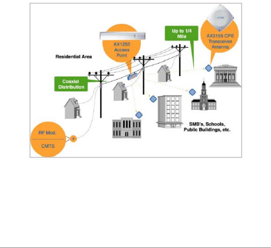
Figure 1-1: ARCXtend System.
Figure 1-1 demonstrates how the ARCXtend system fits into the typical cable
system, and delivers service to buildings unreachable by the cable plant.
1.1 System Overview
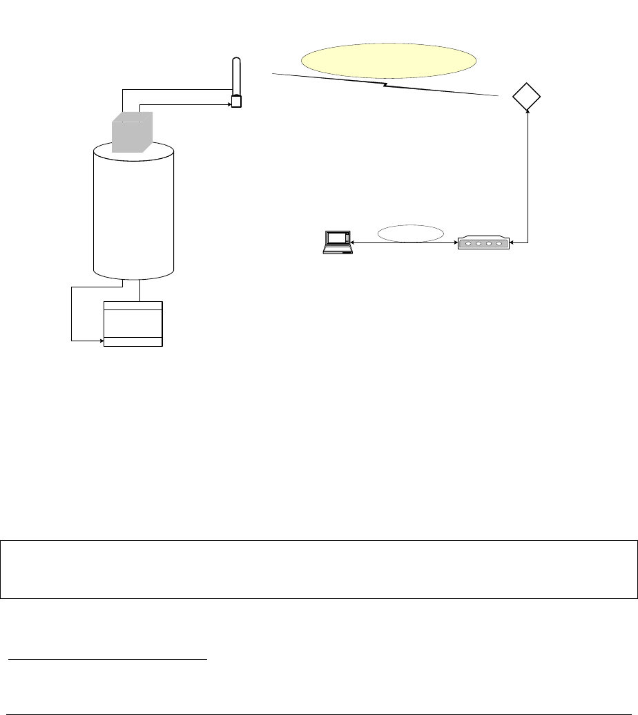
The ARCXtend 5GHz solution consists of an AX1255 Access Point and one or more
AX3155 Subscriber Transceiver/Antennas, as in Figure 1-2.
ARCXtend manual, August 2003 1-1
The AX1255 is a self-contained, weather-protected unit that connects directly to an
existing cable plant. It can be pole, wall, or strand mounted, and line or locally
powered. It provides up to 2-mile coverage over a 90-degree sector, supports over
30Mbs of downstream bandwidth and can support hundreds of cable modems.
The AX3155 Subscriber Transceiver is a small footprint radome that can be easily
mounted on a building or home. It supports delivery of up to 30Mbps of downstream
bandwidth to a customer premise. The radome is weather protected and connects
directly to a DOCSIS compliant cable modem located at the customer premise.
ARCXtend operates in the un-congested license-free 5.3 GHz and 5.8 GHz bands.
ARCXtend
Subscriber
Transceiver
5 GHz band
Modem
Laptop computer
LAN Data
ARCXtend
Access Point
Transceiver
Upstream (Rx)
Downstream (Tx)
CMTS
Cable plant
tap
Figure 1-2: Overview of ARCXtend wireless link.
1.2 Frequency Band of Operation
This system operates in the frequency band designated by the FCC as unlicensed
and is governed by Part 15 of the FCC Rules and Regulations1. The components
that Arcwave sells comply with these Rules.
This device complies with Part 15 of the FCC Rules. Operation is subject to the following two
conditions: (1) this device may not cause harmful interference, and (2) this device must accept
any interference received, including interference that may cause undesired operation.
Briefly, the unlicensed rules for digital devices are:
1 Available at http://ftp.fcc.gov/oet/info/rules/).
ARCXtend manual, August 2003 1-2
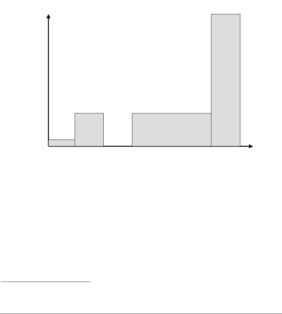
• Lower band is 5.15-5.35 GHz
o Transmitted power in the band 5.25 – 5.35 GHz cannot exceed 250
mW.
o The band 5.15 – 5.25 GHz is for indoor use, and is not used by
ARCXtend.
• Upper band is 5.725-5.850 GHz
o Transmitted power in the band 5.725-5.850 GHz cannot exceed 1
Watt2.
Figure 1-2 shows the maximum allowable power out of an amplifier to illustrate the
above. Each band has complex rules covering other RF parameters.
50 mW
Indoor
only
5.15 5.25 5.35 5.47 5.725 5.850
Frequency (GHz)
250 mW 250 mW
FCC proposal May03
1000 mW
Transmitter Power
Figure 1-2: Transmitter power limitations set by FCC.
1.3 Range
The ARCXtend’s Point-To-Multipoint architecture provides up to 2-mile line-of-sight
coverage over a 90-degree sector and supports up to 30Mbps of downstream and
10 Mbps of upstream bandwidth.
2 In May 2003 the FCC issued a Notice of Proposed Rule Making (NPRM) to enhance the 5 GHz
band. Arcwave is following that NPRM activity and will enhance products as the Rules are finalized.
ARCXtend manual, August 2003 1-3
1.4 CPE Installation
The ARCXtend License-Free, Point-to-Multipoint Wireless Broadband Solution
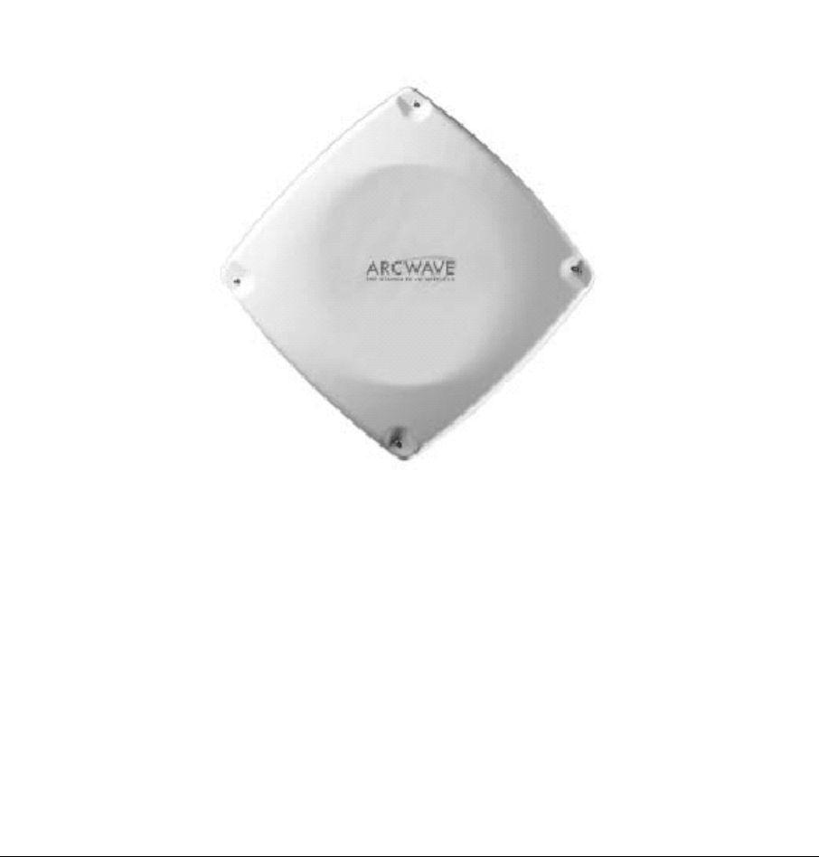
subscriber installation consists of the AX3155 Integrated Subscriber Transceiver
mounted on the exterior of the subscriber facility and the Wireless Cable Modem
(CM) located inside the structure. A single power and signal cable is run between
the Subscriber Transceiver and the modem location. See Figure 1-3.
The Subscriber Transceiver is mounted on a short pipe or bent-arm mounting
arrangement similar to a small satellite TV dish, or a light duty non-penetrating flat
roof mount. It must be in a position with line of sight to the Access Point Transceiver
location. At the time of installation the Subscriber Transceiver is carefully aimed to
transmit and receive to/from the Access Point Transceiver.
Later Sections of this manual provide mounting information and grounding
recommendations for the Subscriber Transceiver.
Figure 1-3: Photo Subscriber Transceiver.
ARCXtend manual, August 2003 1-4
Inside the Subscriber Location, the CM is connected to the PC by means of a
standard Ethernet/LAN cable. Alternatively a LAN hub or switch may be employed
between the CM and the PC(s), as the CM has a gateway function that will support
up to 75 PCs sharing the modem. A small DC inserter device is connected between
the CM and the lead to the outdoor unit. The inserter and most modems each have
cord mounted power supplies.
1.5 Access Point Installation
The multipoint Access Point has two installation options: pole mount and strand
mount.
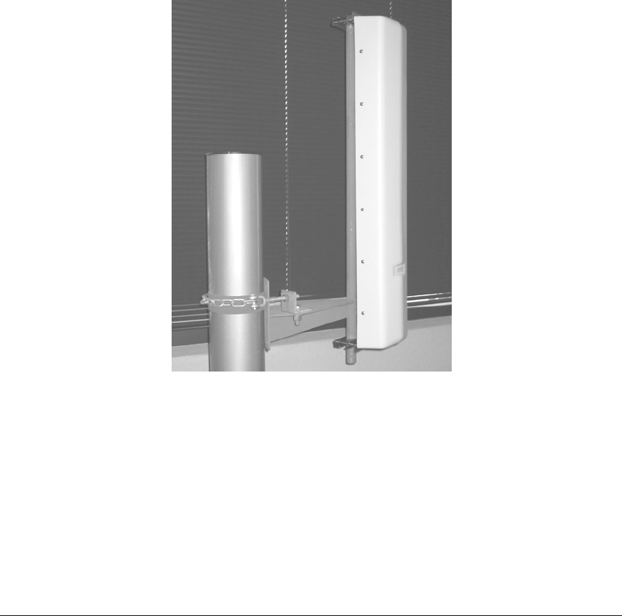
The pole mount option is designed to be placed on a utility pole, as in Figure 1-4,
connected to the cable system tap. It is normally powered from the tap as well, but
other options are available.
The strand-mount option is designed to be suspended from a wire strand between
two utility poles, as in Figure 1-5. It is also normally powered from the tap.
Figure 2-4: Pole-mounted Access Point.
ARCXtend manual, August 2003 1-5
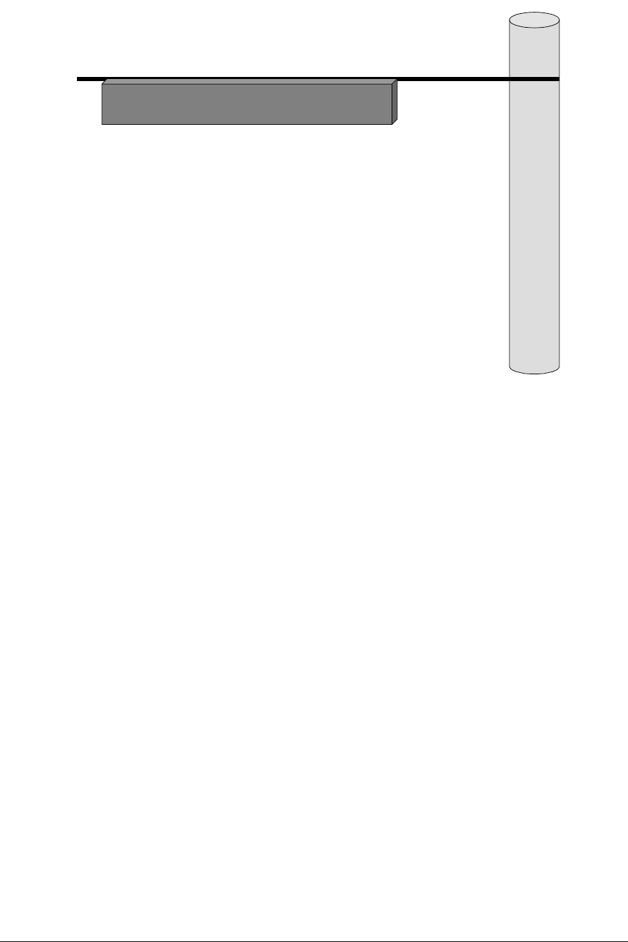
Figure 1-5: Strand-mounted Access Point.
ARCXtend manual, August 2003 1-6
2 Subscriber Installation Details
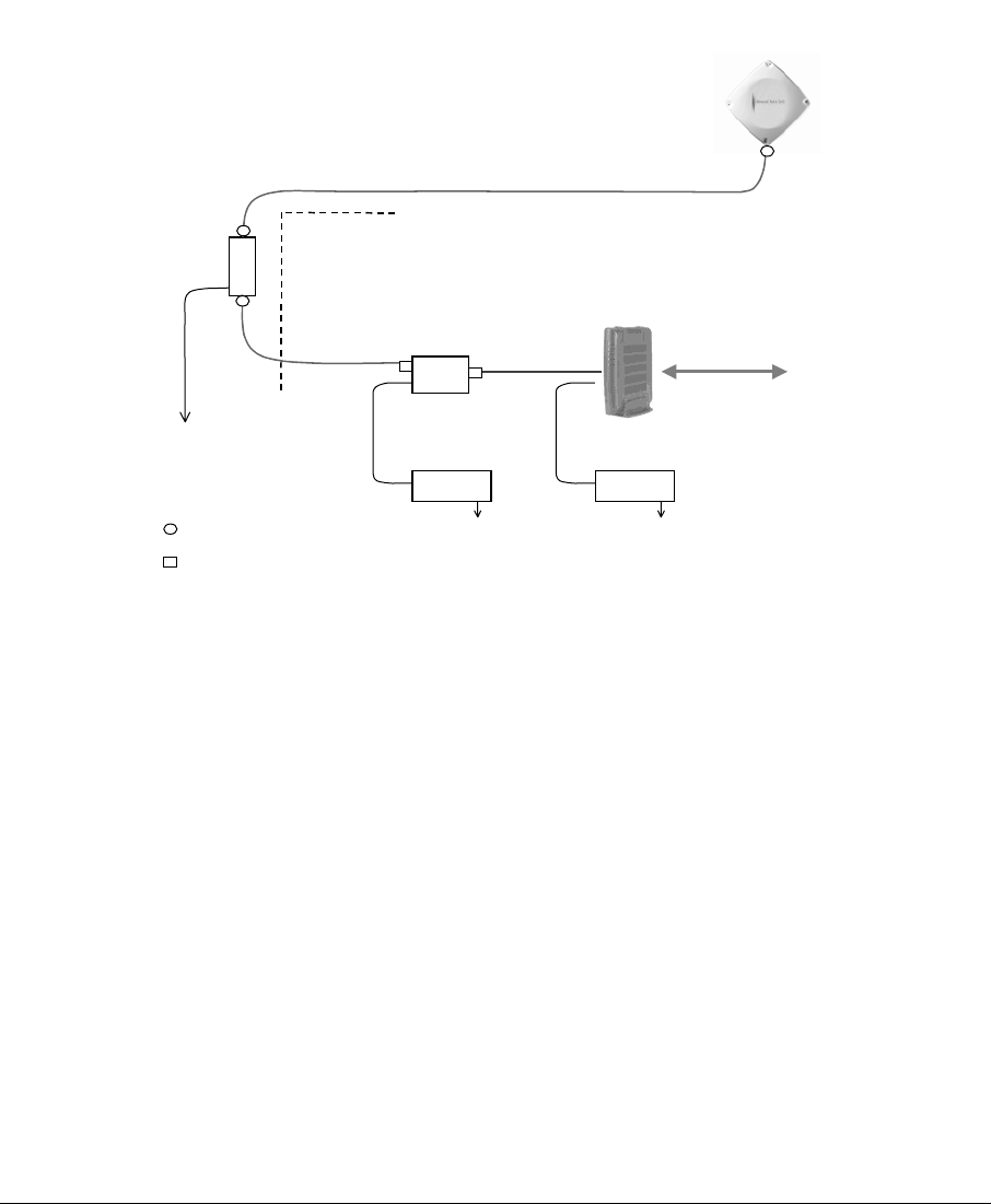
Installation at the subscriber’s site is very simple – one small outdoor unit (the
transceiver) and one cable modem indoors. Power for the outdoor unit is carried
over the TV-type coaxial cable between the two units.
Frequency of operation, RF power, etc. are all determined automatically. There are
no settings to be made on site. The installation diagram is in Figure 2-1.
DC
Inserter
P/Supply P/Supply
Grounding
Device Building
Entrance
Ground
per NEC
LAN
Subscriber
Transceiver
TV cable
(length up to 200 ft.)
TV cable
TV cable
Wireless modem
120 or 220 Vac 120 or 220 Vac
Weatherproof F-type
Indoor F-type connector
Figure 2-1: Schematic diagram subscriber installation.
2.1 Transceiver
The Subscriber Transceiver contains a transmitter, a receiver and the antenna, all in
one integrated weatherized unit that is about 1x1 foot square, as in Figure 2-2.
2.1.1 Mounting
Mount the Subscriber Transceiver on a vertical pipe with at least 12 inches clear of
any hardware or other impediments. The mounting brackets will accommodate pipe
outside diameter (OD) from 1.25 to 2 inches. The front face of the antenna must
point in the direction of the Access Point.
ARCXtend manual, August 2003 2-1
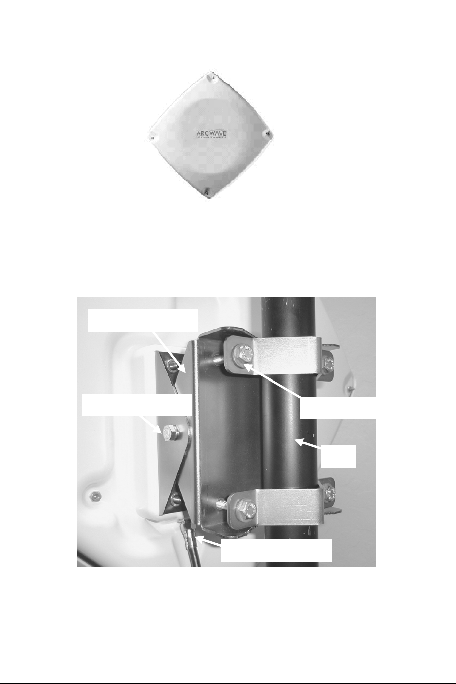
Figure 2-2: Subscriber Transceiver pointing towards Access Point.
Mounting bracket (included)
Elevation alignment bolt
F-connector (before taping)
Pipe
Side/side alignment bolt
Figure 2-3: Subscriber Transceiver mounted on pipe.
ARCXtend manual, August 2003 2-2

2.1.2 Subscriber Transceiver Alignment Methods
There are three recommended methods for aligning the Subscriber Transceiver for
maximum performance:
1. Arcwave Signal Strength Meter
2. Dedicated modem signal meter
3. Spectrum analyzer
4. Channel-selectable cable-TV meter.
They are described below.
All devices are used to measure the downstream signal level received from the base
station. By optimizing the downstream, the upstream is optimized automatically.
Once the particular alignment equipment is chosen, and connected to measure the
downstream signal level (receive), the Subscriber Transceiver is peaked as follows:
1. Using a 7/16” wrench (open end, box or socket), loosen the two elevation
alignment bolts until the Transceiver can be tilted up or down by hand, but will
hold its position.
2. Observe the display of the alignment device being employed and orient the
Transceiver up and down to achieve a maximum peak signal. There may be
other smaller peaks, but the main one should be evident.
3. Tighten the elevation alignment bolts slightly.
4. Using the same wrench loosen the four mounting bolts so the transceiver can
be oriented side to side by hand.
5. Observe the display of the alignment device being employed and orient the
transceiver side to side to achieve a maximum peak signal. There may be
other smaller peaks, but the main one should be evident.
6. Tighten the elevation alignment bolts slightly.
7. Repeat the elevation (up or down) adjustment, and then the azimuth (side by
side) adjustment once again.
8. Tighten the elevation alignment (tilt) bolts, taking care not to over tighten.
9. Tighten the mounting bolts firmly, but do not over tighten as that simply bends
the mounting brackets.
10. Remove the measurement equipment and connect the modem cable.
11. Tape the F-type connector to protect it from weather.
12. Verify the modem’s link to the CMTS is operating properly.
The three pieces of measurement equipment are discussed below.
2.1.3 AR100 Signal Strength Meter
The Arcwave AR100 Signal Strength Meter (SSM), shown in Figure 2-4, is a small
hand held device that is temporarily inserted between the Transceiver end of the
coaxial cable down lead and the Transceiver itself, as in Figure 2-5.
ARCXtend manual, August 2003 2-3
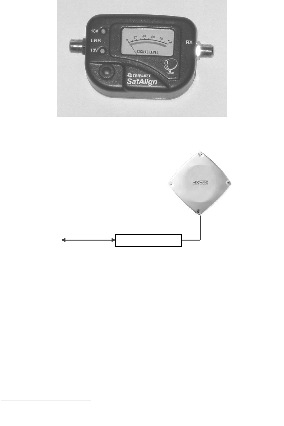
Figure 2-4: AR100 Signal Strength Meter (SSM).
Rx SSM LNB
Cable to modem
Temporary cable
Figure 2-5: AR100 Signal Strength Meter (SSM) at transceiver.
Connect the coax cable from the indoor power inserter to the SSM "Rx" port and a
temporary short coax jumper from the SSM "LNB" port to the Transceiver. The SSM
and the Transceiver will then be powered from the power inserter3.
Align the Transceiver by peaking the signal on the SSM's meter, adjusting the
sensitivity control on the SSM as needed.
Note that the AR100 SSM is a very broadband device that responds to energy below
500 MHz. It will “see” all energy from few hundred MHz to at least 1900 MHz, and
3 The external power jack on the SSM is unused.
ARCXtend manual, August 2003 2-4
thus can be spoofed by a stray signal near the Transceiver and SSM. The AR100 is
a modified Triplett SatAlign SSM.
2.1.4 Sencore DSL757
The Sencore DSL757 Digital Director (www.sencore.com) is a dedicated test device
to meter cable signal levels. One of its basic modes is to display on its LCD screen
the received signal level.
Connect a temporary 2-way splitter to the Subscriber Transceiver and then connect
the Sencore meter to the splitter.. Align the Transceiver by peaking the signal on the
display.
Remove the splitter and connect the modem’s cable to the transceiver. Tape the F-
connector to protect it from the weather.
2.1.5 Spectrum Analyzer
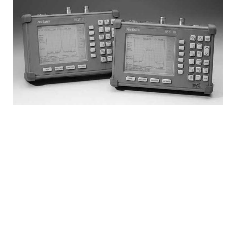
Connect the spectrum analyzer, such as Anritsu MS2711B of Figure 2-6, via a
temporary 2-way splitter at the transducer.
Figure 2-6: Anritsu MS2711 portable spectrum analyzers.
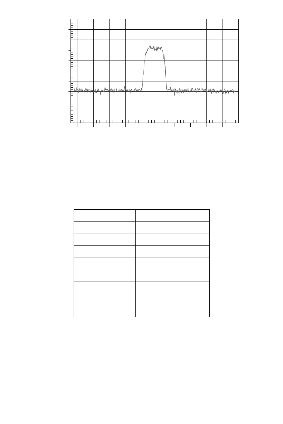
Adjust the spectrum analyzer to display the downstream IF signal from the
Subscriber Transceiver (which will be between 425 and 550 MHz). Reduce the
frequency span and adjust the amplitude to achieve a trace similar to the one in
Figure 2-7.
ARCXtend manual, August 2003 2-5
-50
-40
-30
-20
-10
0
10
20
30
40
435
440
445
450
455
460
465
470
475
480
485
Ref Level :
40.0 dBmV
dB / Div :
10.0 dB
Spectrum Analyzer
GOOD
Model: MS2711B Serial #: 00215050
Date: 05/23/2002 Time: 11:55:01
RBW: 1 MHz VBW: 30 kHz Detection: Average
CF: 459.0 MHz SPAN: 50.0 MHz Attenuation: 0 dB
dBmV
Frequency (434.0 - 484.0 MHz)
Figure 2-7: Proper Downstream IF input to subscriber’s modem.
The spectrum analyzer settings for Figure 2-7 are shown in Table 2-1:
Table 2-1: Typical spectrum analyzer settings.
Parameter Setting
Center Frequency 459 MHz
Span 50 MHz
RBW 1 MHz
VBW 30 kHz
Vertical Scale linear, 10 dB / division
Reference Level +40 dBmV
Attenuation 20 dB
Detection Mode Averaging
Align the subscriber Transceiver antenna as described above, adjusting for
maximum signal amplitude.
2.2 Cable Connection and Grounding
Attach the single RG-6 coaxial cable to the F connector on the rear of the Subscriber
Transceiver. See Figure 2-8. Waterproof the connection using a suitable method
such as taping with Scotch #88. Be sure to leave sufficient slack to allow the
ARCXtend manual, August 2003 2-6
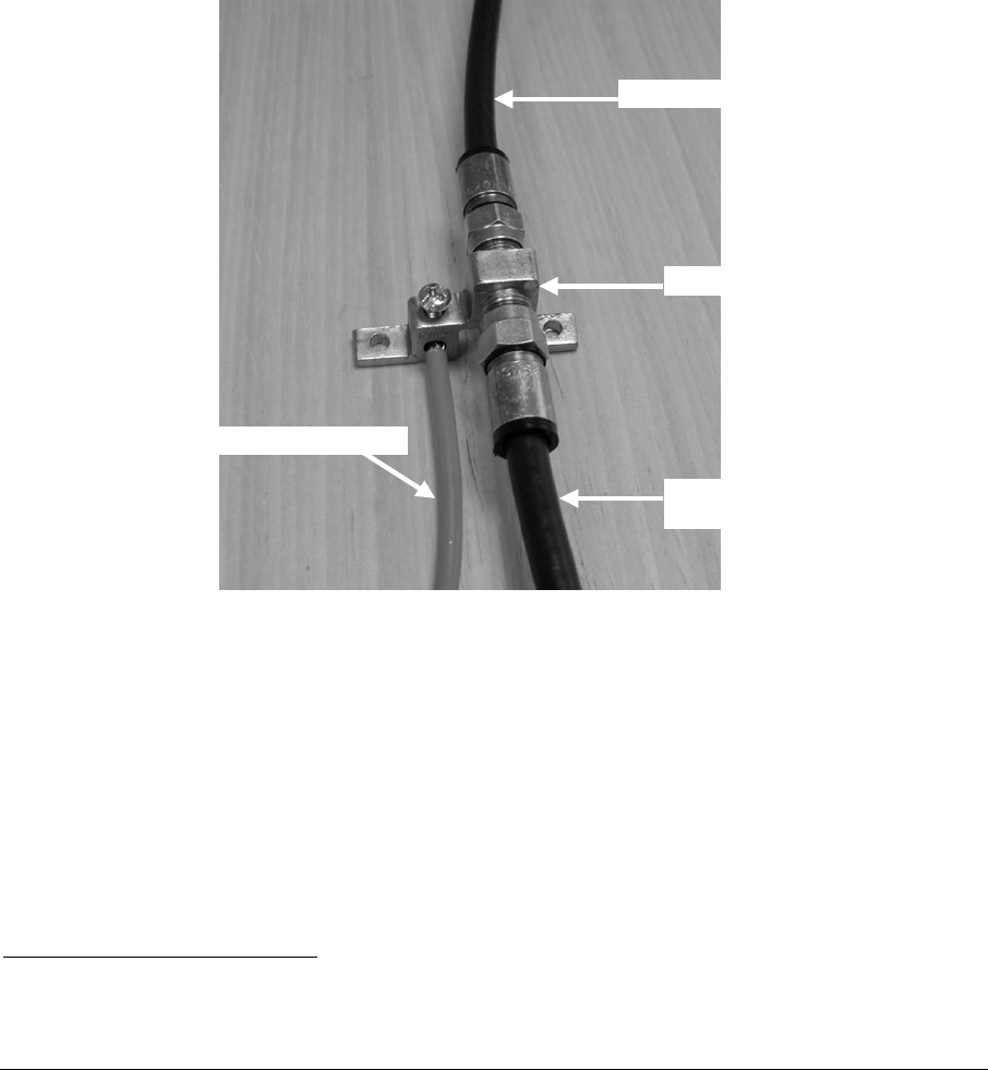
antenna to be oriented and that the cable runs directly downward from the connector
to avoid water running down the cable and into the F connection.
Route the coaxial cable to the building entry point utilizing UV-resistant tie-wraps
and staples or cable clamps as required.
UV-rated cable should be used outdoors, and Riser-rated cable can be used
indoors. In some buildings, a Plenum-rated or riser-rated cable is required. Consult
the local codes.
Mount the grounding device in Figure 2-8 (e.g. Radio Shack 15-909C) as near as
practicable to the point of cable entry to the structure. Connect the grounding device
to a suitable “grounding electrode” following local code.4 Connect the RG-6 coaxial
cable from the Subscriber Transceiver to the grounding device and waterproof all
outdoor-rated F connectors, such as by wrapping them with tape.
To Subscriber Transceiver
Grounding device
Ground wire (green or bare)
To power inserter
& cable modem
Figure 2-8: Typical grounding device at subscriber premises.
2.3 DC Power Supply
The Transceiver is powered over the coaxial cable via a Power Inserter (Figure 2-9)
provided with the Transceiver.
Inside the CPE building, route the RG-6 from the building entrance point to the
wireless cable modem location. Install an F connector on the cable. Connect the
transceiver cable to the “To Antenna” F-type female connector of the Power Inserter.
4 For example, the National Electric Code, sections 820-33 and 820-40, describes this requirement in
detail.
ARCXtend manual, August 2003 2-7
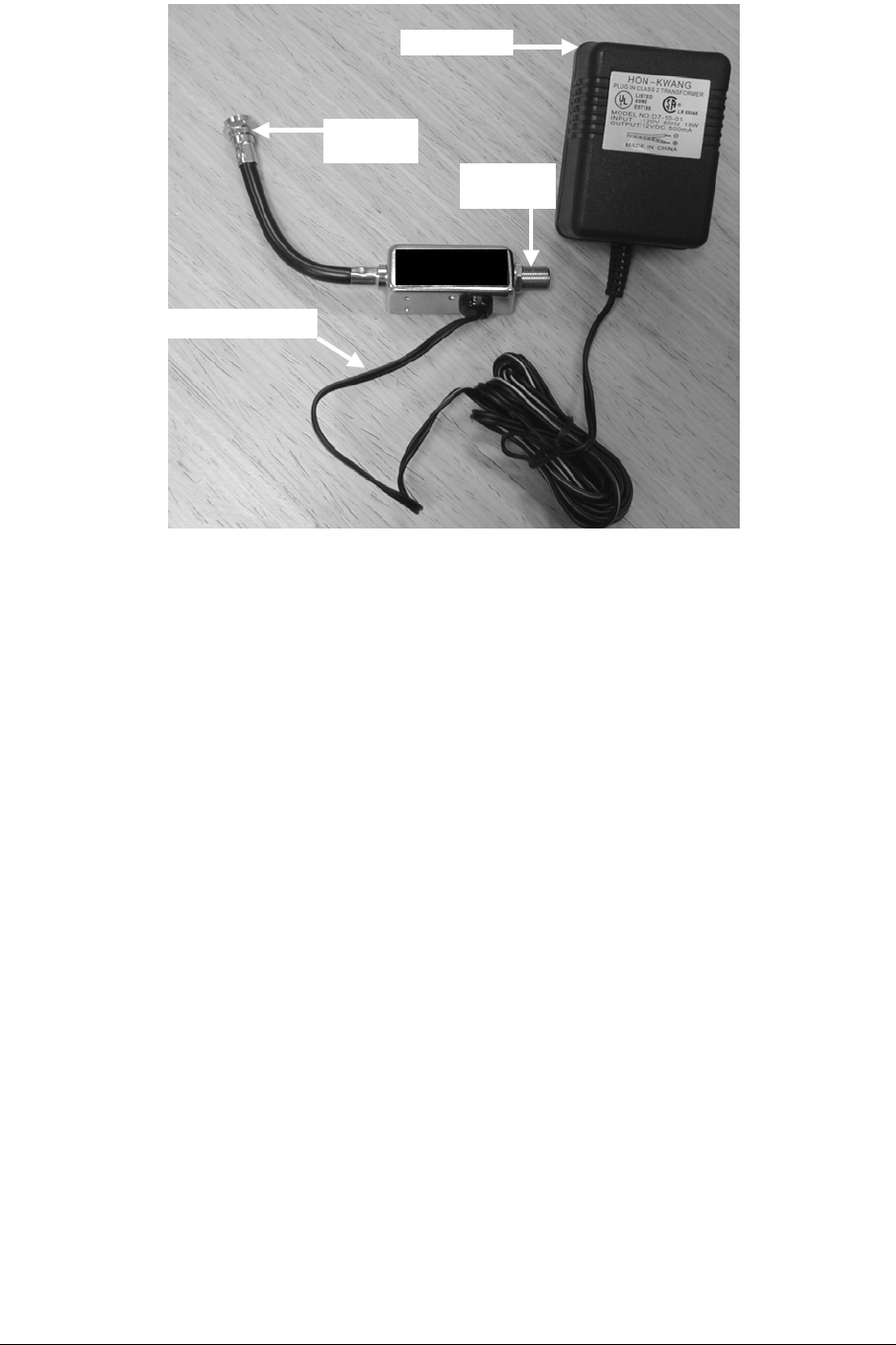
To modem
(no DC)
To AR3155
(with DC)
To AC power
DC power being inserted
to to
modem antenna
Figure 2-9: Power Inserter and AC/DC converter.
2.4 Wireless Cable Modem
Place the wireless cable modem where it will be used and attach the short cable on
the power inserter (labeled “To Modem” in Figure 2-9) to the F connector on the rear
of the modem. Connect the (separate) modem wall-mounted power supply
(included with the wireless cable modem) to the power connector on the rear of the
modem. Plug both wall mounted power supplies into suitable AC power sources –
preferably a UPS or surge protected power strip. Connect a straight-through
10/100BaseT LAN cable between the RJ-45 jack on the modem and the user hub,
router or personal computer.
Figure 2-10 illustrates the modem connections at the back of a typical modem. The
DB-9 connector is a maintenance port for the modem shown.
The CM, when it is first powered up or when it has lost the downstream signal, will
“step” through the standard EIA channel list looking for the downstream signal.
Alternatively, the CM may be optioned through its administrator interface to lock onto
a specific downstream frequency.
ARCXtend manual, August 2003 2-8
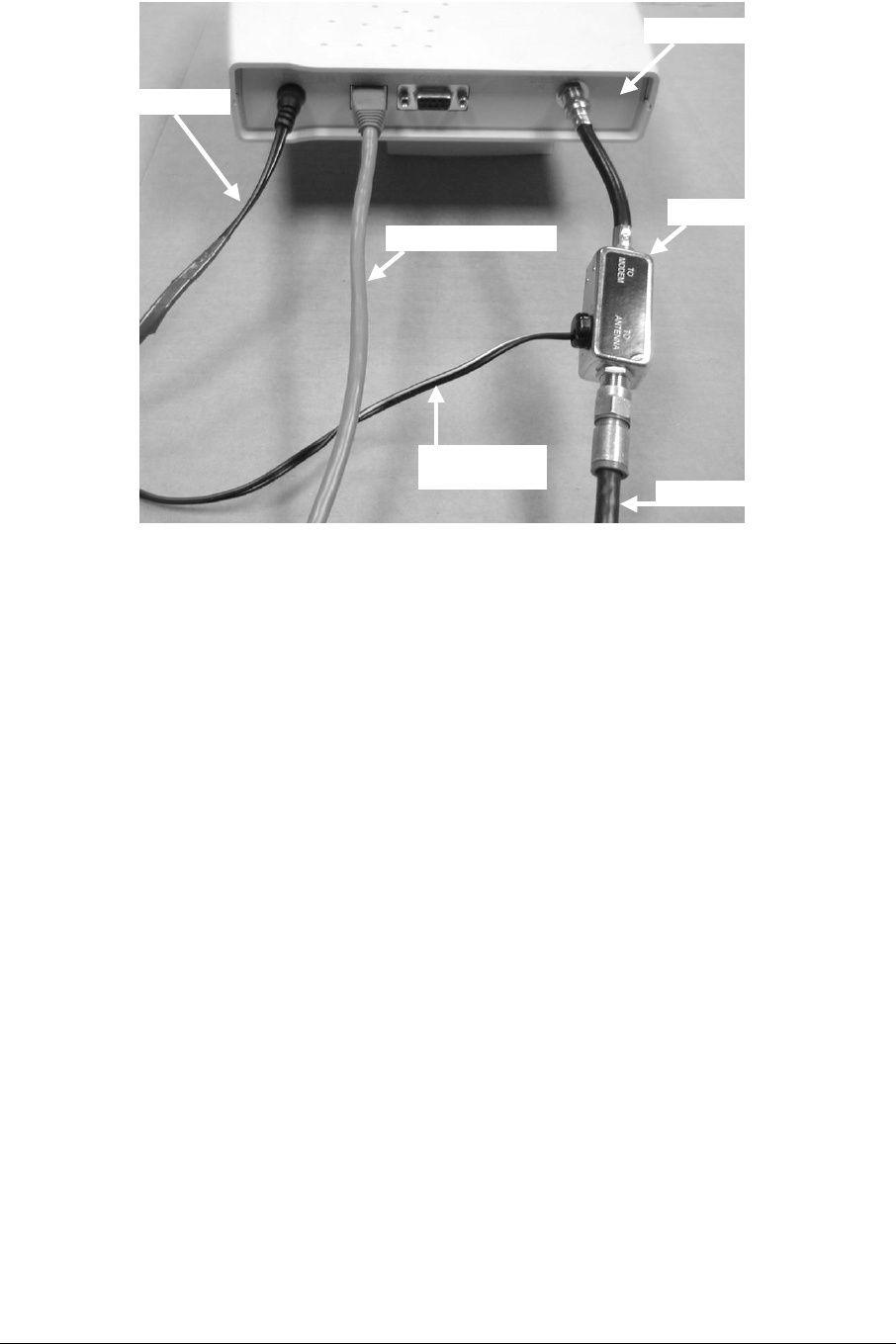
Power inserter
Cable to AR3155
Modem rear panel
Modem power
Ethernet (LAN) cable
Power inserter
power cord
Figure 2-10: Rear view of typical wireless cable modem.
2.5 Frequency Channel
The cable modem will automatically search for the active channels, will go through a
handshake with the CMTS, will be told all the parameters it will need to join the
wireless network and will be authenticated/authorized to join.
2.6 Modem http Interface
The modem status can be determined by the LEDs and by a browser interface.
The typical modem LEDs and their use are:
Power: ON = power OK
Cable: ON = ranged & registered with CMTS, blinking= in process
LAN: ON = connected
USB: ON = connected [some modems have both USB & LAN connectors]
Activity: blinking = data (transmit or receive)
The browser interface is available on some modems and contains more information.
The typical instructions in the user manual are to follow these steps:
Connect a PC to either the modem’s USB or the Ethernet interface
Launch the PC’s browser, such as Microsoft’s Internet Explorer
Address: http://192.168.100.1
ARCXtend manual, August 2003 2-9
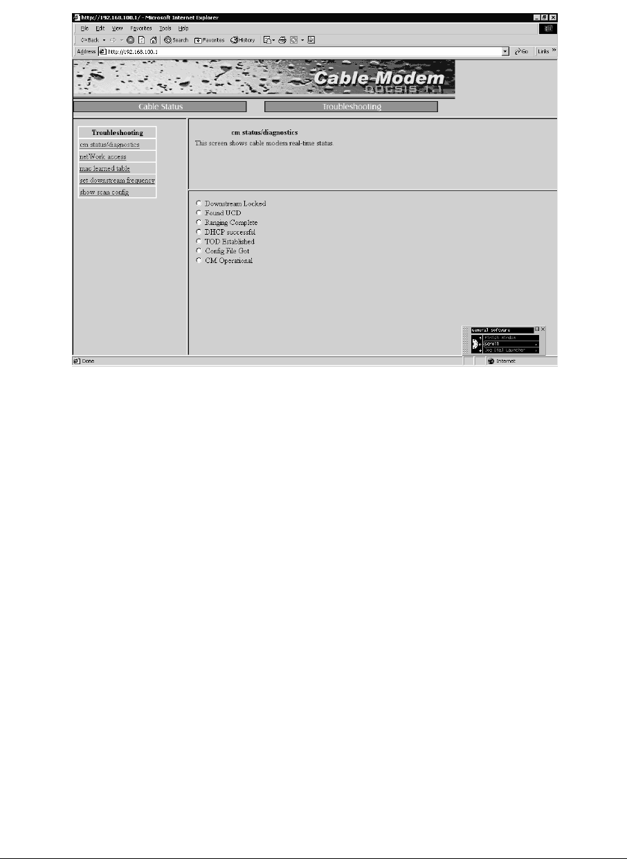
User: (leave this blank)
Password: cable
The typical modem screen looks like Figure 2-11.
Figure 2-11: Screen for cable modem status.
2.7 Installations Close to Access Point
Subscriber installations that are very close to the Access Point may have a situation
where the input to the cable modem is overloaded. An overloaded input usually
causes lack of synchronization and/or a high error count. If this is suspected, try a 6,
10 or 20 dB pad/attenuator at the modem input and see if the modem starts to lock
and be error free. If so, leave the pad in place.
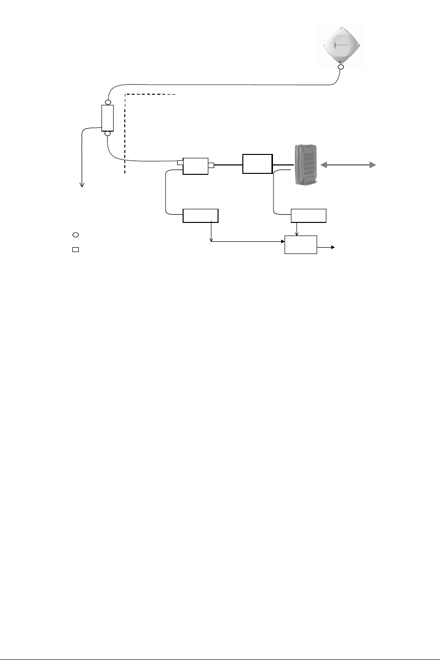
The subscriber installation Schematic Diagram (Figure 2-13) shows a “Pad” installed
between the power inserter and the wireless cable modem (the “dry” side of the
power inserter). Small pads of many values are available with F-type connectors to
screw in-line with the coaxial cable connection, such as Channel Visions #3000-10.
Figure 2-12 also shows the recommended UPS that most customers already have
for their router and other LAN equipment.
At the time of system set-up it may be determined that such pads are required in
subscriber installations extremely close (less than a mile) from the Access Point site
to reduce excess downstream signal.
A spectrum analyzer is another way to check symptoms of overloading.
ARCXtend manual, August 2003 2-10
DC
Inserter
P/Supply P/Supply
Grounding
Device Building
Entrance
Ground
per NEC
LAN
Subscriber
Transceiver
TV cable
(length up to 200 ft.)
TV cable
TV cable
cable modem
120 or 220 Vac
Weatherproof F-type
Indoor F-type connector
pad
UPS
Figure 2-12: Adding pad to eliminate overload.
ARCXtend manual, August 2003 2-11

3 Access Point Installation
The Access Point is installed at a point on the cable system plant where it can reach
a number of customers.
3.1 Site Survey
Paper records of what is at a specific site are notoriously poor, so it is always best to
preview the installation by visiting the site.
3.1.1 Physical plant
A decision has to be made about mounting the Access Point Transceiver. It can be
mounted on a utility pole or on a wire strand.
Another factor to plan is the powering – will it be powered from the coaxial cable tap,
or from the local utility AC.
The tap has to be found that will serve the Access Point. Some coaxial cable may
be needed to extend the tap a few feet to reach the Access Point’s planned location.
The Access Point should be located so it has the best line-of-sight coverage of the
desired customer area.
Grounding the Access Point must be planned to minimize damage from lightning
surges and accidental power crosses to the coaxial cable plant.
3.1.2 5 GHz Usage
The RF must also be planned. Usually the 5 GHz band is lightly used, since
microwave ovens, cordless phones, etc. do not generally use this band. If, however,
the band is already heavily used, then a survey with a spectrum analyzer is the best
way to determine which channel to use to reach the customers.
3.2 Antenna Patterns
Each Access Point Transceiver has a built-in antenna, with the strongest power
straight out from the antenna’s axis. The antenna’s axis is perpendicular to the
radome covering it.
Elevations above straight out from the front of the antenna (up into the sky) receive
less power, as do elevations below straight out. Therefore, the antenna is normally
pointed at the furthest subscriber to be served, with the lower elevations providing
appropriately less power to closer subscribers. This pointing is usually referred to as
“downtilt”. Most installations do not require a downtilt.
The Access Points are available in two basic models, one designed for vertical
mounting and the other for horizontal mounting. They differ in antenna polarization
and mounting hardware. The descriptive model name is Strand Mount and Pole
Mount. In both mounts, the resulting transmitted signal is vertically polarized when it
leaves the Access Point.
ARCXtend manual, August 2003 3-1
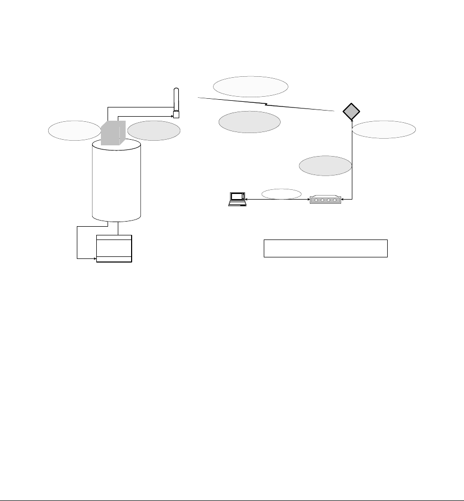
3.3 Frequency Planning – Downstream
This Section describes some of the issues involved in planning a wireless network
deployment.
The ARCell wireless system uses different frequencies for Downstream (Access
Point to subscriber) and Upstream (subscriber to Access Point) communications,
which is referred to as a Frequency Division Duplex (FDD) system.
The Downstream uses a channel within the unlicensed 5 GHz “high” band, 5.725-
5.850 GHz. Upstream uses a channel within the “low” band, 5.250-5.350 GHz.
To cover a large metropolitan area, some pre-planning is needed for the use of the
right channels at each location.
6.4 <> 41.6
U/S IF
200 <> 860
D/S IF
ARCXtend
Subscriber
Transceiver
5729 <> 5843
D/S AIR
5258.4 <> 5341.6
U/S AIR
Modem
425<>550
D/S IF
6.4 <> 41.6
U/S IF
Laptop computer
LAN Data
All Frequencies are channel center in MHz
ARCXtend
Access Point
Transceiver
Upstream (Rx)
Downstream (Tx)
CMTS
Cable plant
tap
Figure 3-1: Frequency Plan.
Figure 3-1 illustrates the range of frequencies:
a) The Figure shows that Downstream be any frequency in the range 200
to 860 MHz. This is usually the frequency used by the wired modems.
b) The Access Point Transmitter modulates this channel to the 5.8 GHz
band..
c) The Subscriber Receiver Downconvert 5.8GHz signal to the 425-550
MHz IF, which is a standard CATV channel the modem can detect.
d) The modem hunts for this channel and the DOCSIS protocol. This IF
frequency is often different from the CMTS downstream frequency.
ARCXtend manual, August 2003 3-2

e) Going in the Upstream, the modem output (transmit) upstream is
whatever the CMTS configuration has instructed, which is in the range
of 6.4 to 41.6 MHz.
f) The Subscriber Transmitter (inside the CPE Transceiver) up-converts
this IF channel to the 5.3 GHz band, which goes over the air to the
Access Point Receiver. The RF transmission is scheduled by the
DOCSIS protocol, so that it does not interfere with other modem
transmission on this channel.
g) The Access Point Receiver tuned to 5.3 GHz band, down-converts this
to the upstream channel 6.4 to 41.6 MHz.
h) The CMTS Upstream port detects the 6.4-41.6 MHz upstream signal.
Table 3-1: EIA Channel numbers and Downstream Center Frequency
EIA
CATV
Channel
CATV
Video
Edge
AX
Center
6MHz
EIA
CATV
Channel
CATV
Video
Edge
AX
Center
6MHz
EIA
CATV
Channel
CATV
Video
Edge
AX
Center
6MHz
23 217.25 219 59 433.25 435 102 661.25 663
24 223.25 225 60 439.25 441 103 667.25 669
25 229.2625 231 61 445.25 447 104 673.25 675
26 235.2625 237 62 451.25 453 105 679.25 681
27 241.2625 243 63 457.25 459 106 685.25 687
28 247.2625 249 64 463.25 465 107 691.25 693
29 253.2625 255 65 469.25 471 108 697.25 699
30 259.2625 261 66 475.25 477 109 703.25 705
31 265.2625 267 67 481.25 483 110 709.25 711
32 271.2625 273 68 487.25 489 111 715.25 717
33 277.2625 279 69 493.25 495 112 721.25 723
34 283.2625 285 70 499.25 501 113 727.25 729
35 289.2625 291 71 505.25 507 114 733.25 735
36 295.2625 297 72 511.25 513 115 739.25 741
37 301.2625 303 73 517.25 519 116 745.25 747
38 307.2625 309 74 523.25 525 117 751.25 753
39 313.2625 315 75 529.25 531 118 757.25 759
40 319.2625 321 76 535.25 537 119 763.25 765
41 325.2625 327 77 541.25 543 120 769.25 771
42 331.275 333 78 547.25 549 121 775.25 777
43 337.2625 339 79 553.25 555 122 781.25 783
44 343.2625 345 80 559.25 561 123 787.25 789
45 349.2625 351 81 565.25 567 124 793.25 795
ARCXtend manual, August 2003 3-3

46 355.2625 357 82 571.25 573 125 799.25 801
47 361.2625 363 83 577.25 579 126 805.25 807
48 367.2625 369 84 583.25 585 127 811.25 813
49 373.2625 375 85 589.25 591 128 817.25 819
50 379.2625 381 86 595.25 597 129 823.25 825
51 385.2625 387 87 601.25 603 130 829.25 831
52 391.2625 393 88 607.25 609 131 835.25 837
53 397.2625 399 89 613.25 615 132 841.25 843
54 403.25 405 90 619.25 621 133 847.25 849
55 409.25 411 91 625.25 627 134 853.25 855
56 415.25 417 92 631.25 633
57 421.25 423 93 637.25 639
58 427.25 429 94 643.25 645
100 649.25 651
101 655.25 657
3.3.1 Available Channels
There are 18 available downstream 6 MHz channels in the ARCXtend standard
5.725-5.850 GHz band.
Table 3-1: Downstream Air Center Frequencies
Downstream
Air Transmit
Center
Frequency
(MHz)
5729
5735
5741
5747
5759
5765
5771
5777
5783
5789
5795
5807
ARCXtend manual, August 2003 3-4

5813
5819*
5825*
5831*
5837*
5843*
NOTE: 5753 and 5801 MHz are not used.
At the CPE, the downstream 5.8 GHz frequency is translated into an intermediate
frequency (IF) that the cable modem hunts to and locks on, as in Table 3-2.
Table 3-2: Downstream Frequency Plan at CPE
Downstream
Receive (from
the air)
Modem IF Input
(from CPE
transceiver) Modem Channel
Center freq.
(MHz)
Center freq.
(MHz) EIA TV Channel #
5729 429 58
5735 435 59
5741 441 60
5747 447 61
5753 453 62
5759 459 63
5765 465 64
5771 471 65
5777 477 66
5783 483 67
5789 489 68
5795 495 69
5801 501 70
5807 507 71
5813 513 72
5819* 519 73
5825* 525 74
5831* 531 75
5837* 537 76
5843* 543 77
Downstream air frequencies 5819 MHz through 5843 MHz are not yet FCC approved.
ARCXtend manual, August 2003 3-5
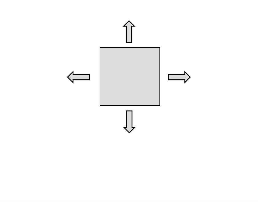
3.3.2 Downstream Adjacent 90-degree Sectors
The 90-degree-Sector Transceiver has a half-power horizontal beam width of 90
degrees, i.e., 45 degrees each side of center, call the “bore sight” of the antenna.
But, the energy of the antenna does not simply cut off at 45 degrees in horizontal
pattern from the centerline of the antenna. Rather, the energy falls off as the angle
from the centerline increases. A typical antenna pattern is shown in Section on
Basic RF.
This means that a subscriber in the vicinity of 45 degrees clockwise from antenna A
will also be in the vicinity of 45 degrees counterclockwise from adjacent antenna B.
Subscribers in the overlap zone – especially if they are relatively close to the Access
Point – will receive downstream signals from both adjacent Access Point
Transceivers. This will cause unacceptable interference if both Access Point
Transceivers are transmitting on the same frequency, even though the subscriber is
receiving nominally the same signal from both Access Point Transceivers.
The solution for this is to ensure that adjacent Access Point Transceivers are never
transmitting on the same frequency. Two downstream frequencies (A & B) are
required for an omnidirectional system employing 4x90-degree Access Point
Transceivers. Figure 3-2 shows the recommended ABAB pattern.
AA
B
B
Omnidirectional
Hub
4x90-sectors
Figure 3-2: Downstream Channel Example of ABAB.
ARCXtend manual, August 2003 3-6
3.3.3 Downstream Logical Channels
It is important to note the distinction between “downstream frequencies” and
“downstream logical channels”. The “downstream frequencies” (A & B) discussed
above refer to the actual RF carrier frequencies transmitted over the air.
“Downstream logical channel” refers to the downstream data stream at the output of
a base station CMTS downstream module. In the examples here, the frequencies
employed may be driven from one to two downstream logical channels. The
difference lies in the traffic capacity of the Access Point.
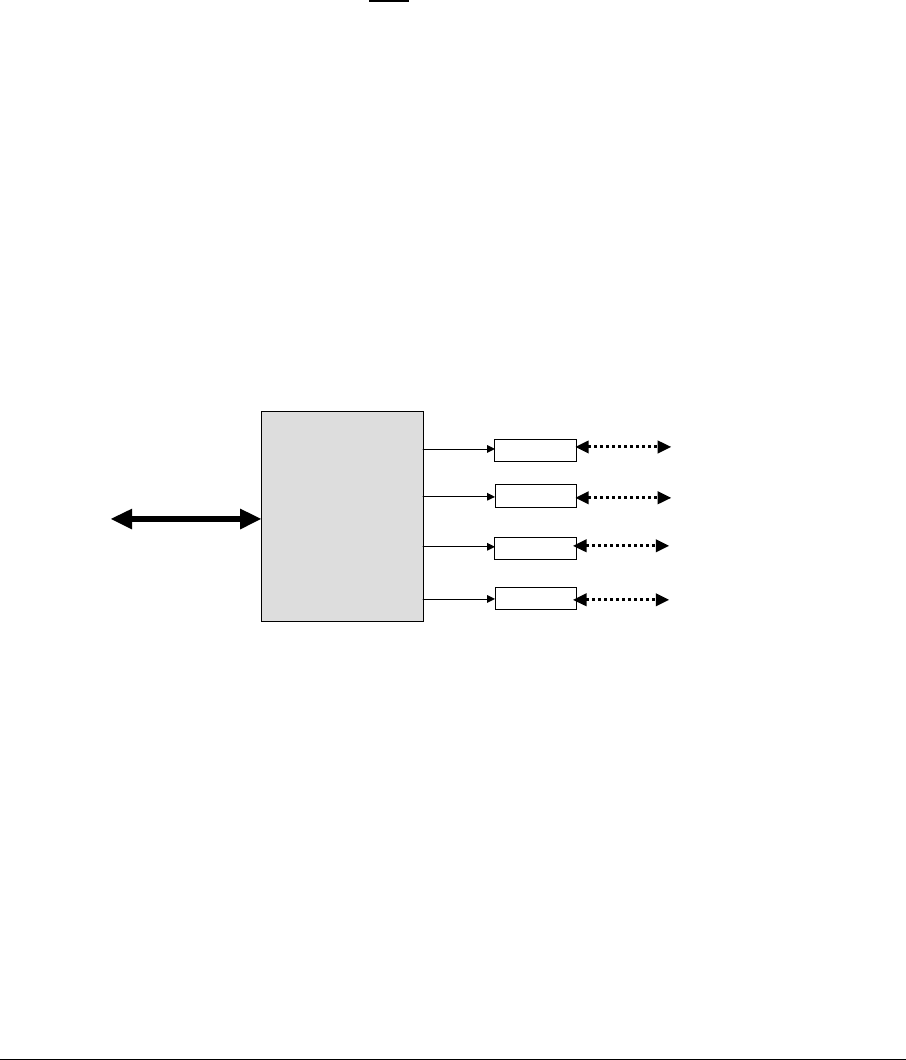
For example, Figure 3-3, below, illustrates a 4-sector system that utilizes the ABAB
downstream frequency pattern for one downstream logical channel, which is split
ultimately to all four sectors. This system has an aggregate raw downstream
capacity of 31 Mbps downstream using 64QAM modulation.
The same Figure 3-3 has two Upstream air frequencies in an XYXY pattern which
can be mapped into one or two upstream cable channels discussed in the next
section.
4-port cable tap
Trans/Ant 1
Trans/Ant 2
Trans/Ant 3
Trans/Ant 4
Fa, Fx
Fb, Fy
Fa, Fx
Fb, Fy
Cable system
Figure 3-3: Four-Sector ABAB System with 1 downstream data stream.
3.4 Frequency Planning – Upstream
This Section discusses several issues related to planning the use of the frequency
band for Upstream communications.
3.4.1 Upstream Logical Channels
It is important to recall that any given downstream logical channel may have a large
number of upstream logical channels associated with it, and that any given upstream
ARCXtend manual, August 2003 3-7

is always associated with one and only one downstream. The association of one or
more upstream logical channel with a downstream logical channel is made in the
CMTS configuration. Upstream logical channels from one or more Access Point
Transceivers may not be combined into a single upstream input to the CMTS.
3.4.2 Upstream Frequencies
The cable modem at the customer site obeys the various protocols within the cable
plant. One of these determines the frequency that the cable modem operates on for
both upstream and downstream.
The CPE Transceiver modulates the modem upstream output and puts it over the air
in the 5.3 GHz ISM band as a double-sideband signal. The Access Point Receiver
is tuned to one of the carriers. The AP Receiver demodulates the received
frequency down into the same cable frequency the modem transmitted, and places it
on the cable system.
3.4.3 Available Frequencies
All wireless modems in the same Access Point sector must transmit upstream on the
same frequency, and each wireless modem can operate on only one upstream
channel.
The Upstream data rate is 5.12 Mbps with Channel Bandwidth of 3.2 MHz.
Table 3-2 shows the modem Upstream frequencies, and the corresponding
Upstream Air frequency used by the subscriber transducer.
The CMTS commands the wireless modem to its Upstream Transmit Carrier
frequency during the wireless modem registration process. These are configuration
parameters that are set in the CMTS network management system. See the
software installation guide for that product.
Some operators combine multiple Upstreams from different nodes. This may dictate
the upstream channel for the wireless modems. Combining Upstreams tends to
save on capital equipment, but will limit the traffic that can be carried. This balance
of cost/performance tradeoff is usually different for business customers than
residential customers.
ARCXtend manual, August 2003 3-8

Table 3-2: Upstream Frequency Plan5
Modem US &
Cable System
US Channel
Upper Carrier
CPE air Tx &
Access Point
Rx
Lower Carrier
CPE air Tx &
Access Point
Rx
center (MHz) center (MHz) center (MHz)
fch 5300+ fch 5300- fch
6.4 5306.4 5293.6
9.6 5309.6 5290.4
12.8 5312.8 5287.2
16.0 5316.0 5284.0
19.2 5319.2 5280.8
22.4 5322.4 5277.6
25.6 5325.6 5274.4
28.8 5328.8 5271.2
32.0 5332.0 5268.0
35.2 5335.2 5264.8
38.4 5338.4 5261.6
41.6 5341.6 5258.4
This mapping of the modem upstream channel to the over-the-air 5.3 GHz channels
(double sideband modulation) is fixed. Should interference or other factors force the
choice of a specific 5.3 GHz channel, the Access Point Receive Frequency should
be flipped to the alternate frequency. This is done through the Access Point control
interface.
3.5 Example of Frequency Plan
The system in Figure 3-4 is an example of a frequency plan at one Access Point.
The CMTS Downstream is EIA Channel 93 (639 MHz) for wired and wireless
modems.
The ARCXtend Access Point is programmed to convert this into a Downstream air
frequency of 5777 MHz (the programming is covered in a later Section).
5 A spectrum analyzer looking at the subscriber’s transmitted RF will see two frequencies. The two
carriers are 5300 MHz +- the upstream IF frequency. The Hub receiver is tuned to only one of these
two frequencies.
ARCXtend manual, August 2003 3-9
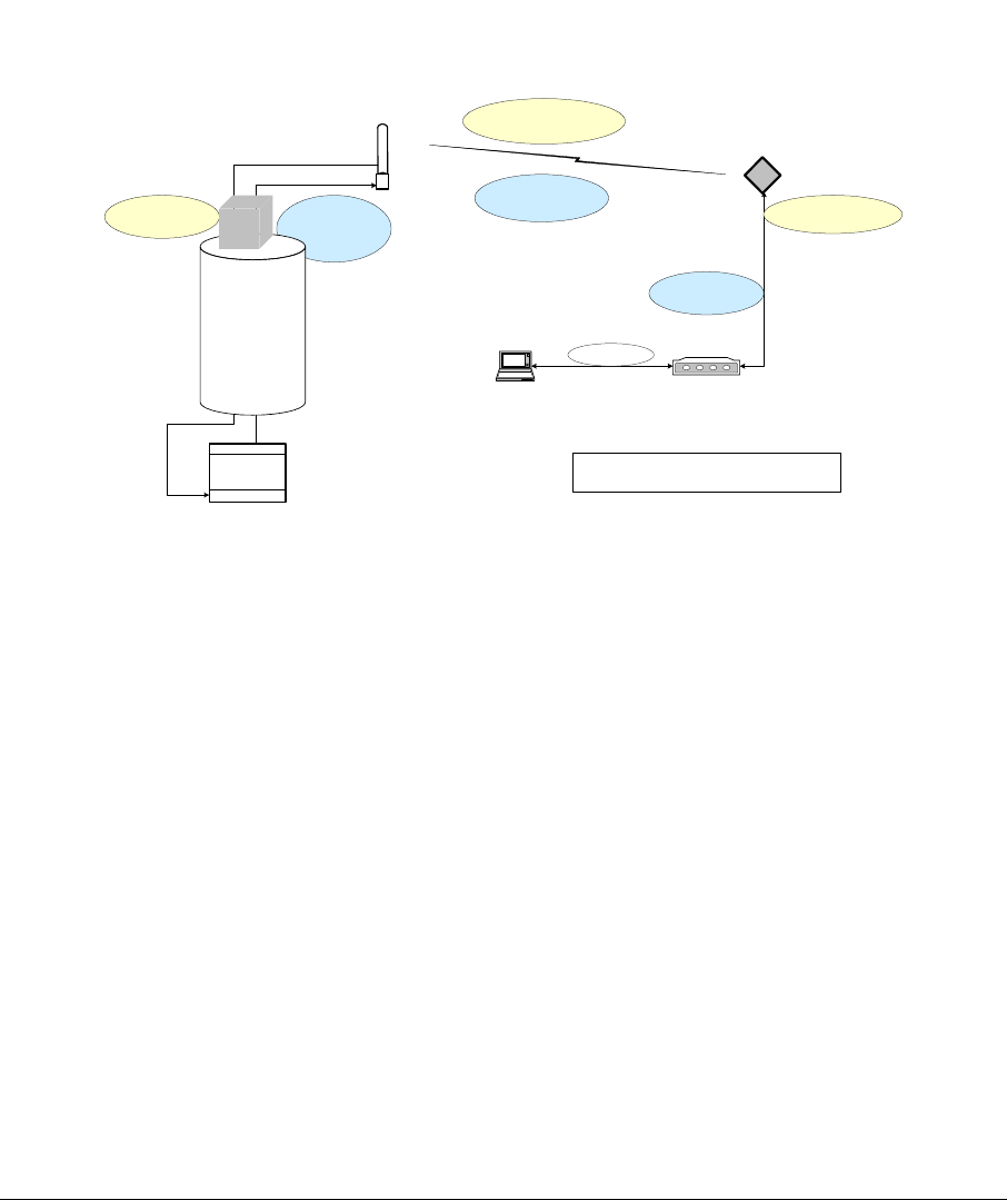
The ARCXtend CPE Transceiver converts the 5777 MHz to 477 MHz.
The cable modem locks onto the 477 MHz DS signal, handshakes with DOCSIS,
and it instructed to use an upstream of 12.8 MHz.
The CPE Transceiver converts the 477 MHz to 5287.2 & 5312.8 MHz and transmits
these over the air to the Access Point.
The Access Point is configured to receive only the 5287.2 MHz and is configured to
convert it to 12.8 MHz Upstream, which goes into the tap.
6.4 <> 41.6
U/S IF 12.8
200 <> 860
D/S IF 639
(EIA93)
ARCXtend
Subscriber
Transceiver
5729 <> 5843
D/S AIR 5777
5258.4 <> 5341.6
U/S AIR 5287.2
Modem
425<>550
D/S IF 477
6.4 <> 41.6
U/S IF 12.8
Laptop computer
LAN Data
All Frequencies are channel center in MHz
ARCXtend
Access Point
Transceiver
Upstream (Rx)
Downstream (Tx)
CMTS
Cable plant
tap
Figure 3-4: Example of a frequency plan.
3.6 Power
The Access Point has a few power options. The choice is usually made during the
site survey. The choices are:
a) Cable powered
b) Local utility power
3.6.1 Cable Powered
The most common powering is via the power on the coaxial cable itself.
The CATV industry AC power is normally square-wave 60-90 Vac, 60 Hz.
Another Access Point model can be powered from DC on the coax. It can be
powered with 8-24 Vdc. If the cable system doesn’t have the dc, a coaxial DC
inserter can be used.
ARCXtend manual, August 2003 3-10
3.6.2 Local Utility Powered
Other powering is possible, using external converters from whatever the local utility
provides, into DC, 8-24 Vdc. This is connected to the Access Point power
connector.
In this application, the cable system tap passes only RF.
3.7 Pipe Mount Installation
The Access Point Mast Mount Kit is designed to mount the AP on a pipe.
The pipe size should be between 1.5 and 2.25 inches, outside diameter (OD).
The cable goes out the bottom of the Access Point.
The pipe can be mounted on a building roof, side of a building, side of a tower, or on
a utility pole.
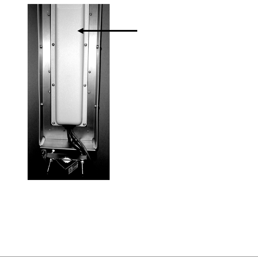
Figure 3-5 shows the weather cover as a rear view of the Access Point on a pipe.
Rear weather cover
Figure 3-5: Access Point mounted on pipe.
Figure 3-6 shows the pipe mounting kit pieces. There are two such bracket pairs in
the Mounting Kit.
ARCXtend manual, August 2003 3-11
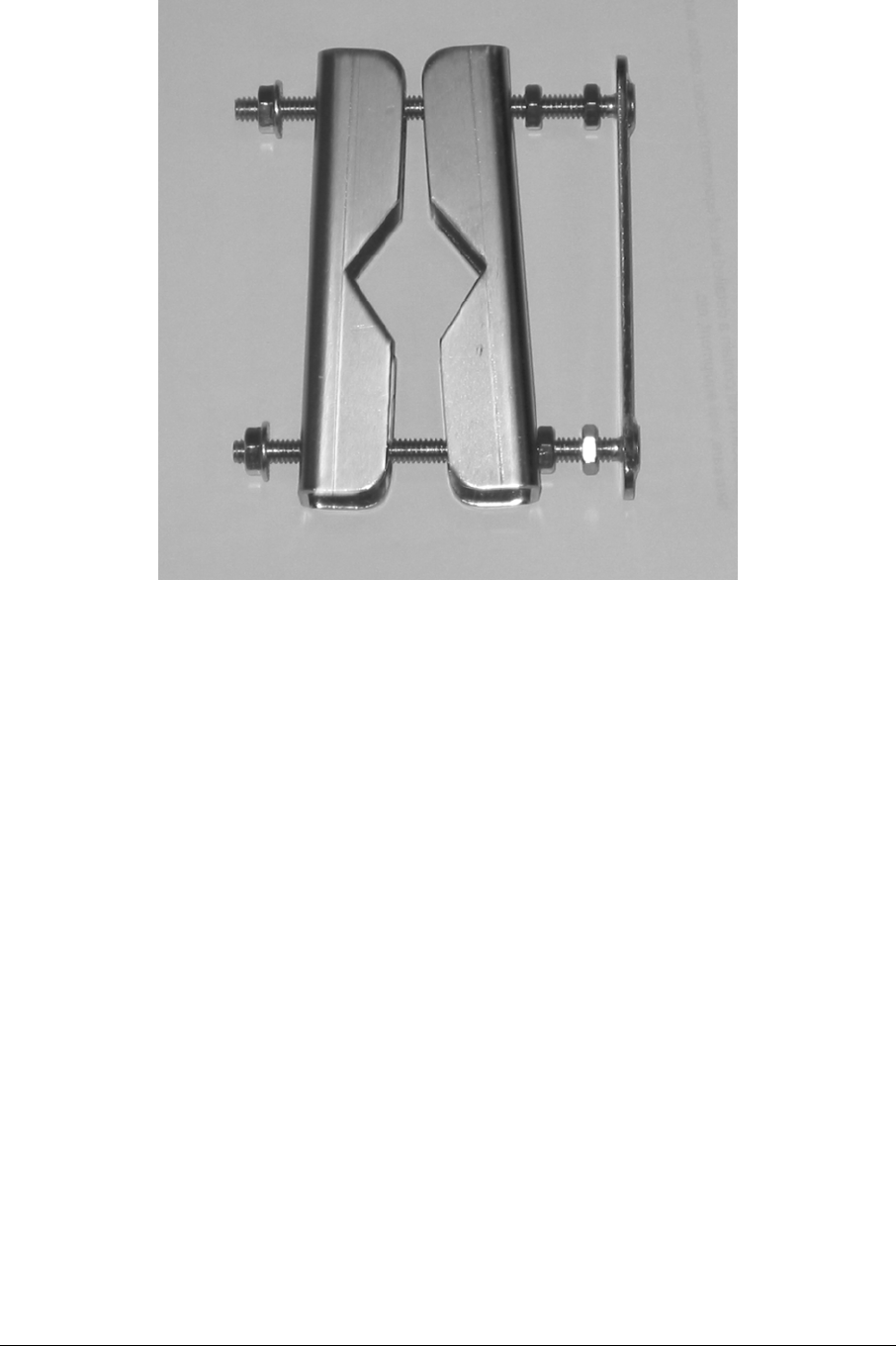
Figure 3-6: Pipe mounting kit (1 of 2)
Figure 3-7 shows the detail of the cable coming out of the bottom of a pipe-mounted
Access Point.
ARCXtend manual, August 2003 3-12
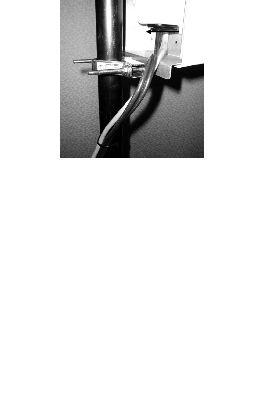
Cable entry
Figure 3-7: Access Point Cable Installation detail.
3.8 Pole Mount
The decision of pole mount vs. strand mount is totally governed by local practices.
Some administrations prefer one over the other based on cost, tariffs, access, etc.
Figure 3-8 and 3-9 show the pole details of the Pole Mount Kit.
ARCXtend manual, August 2003 3-13
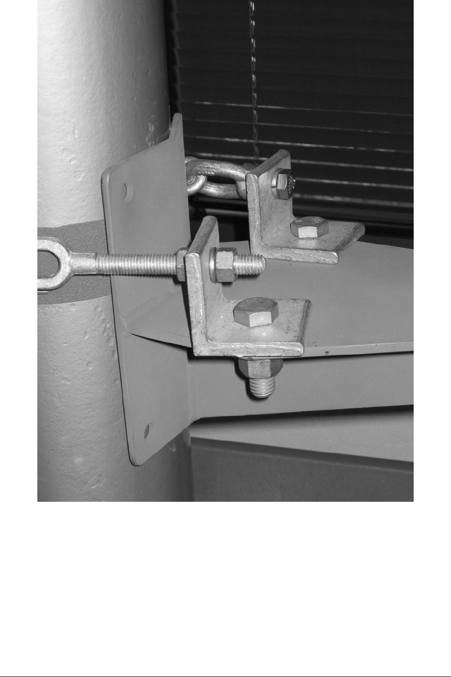
Figure 4-8: Pole-mount kit detail.
ARCXtend manual, August 2003 3-14
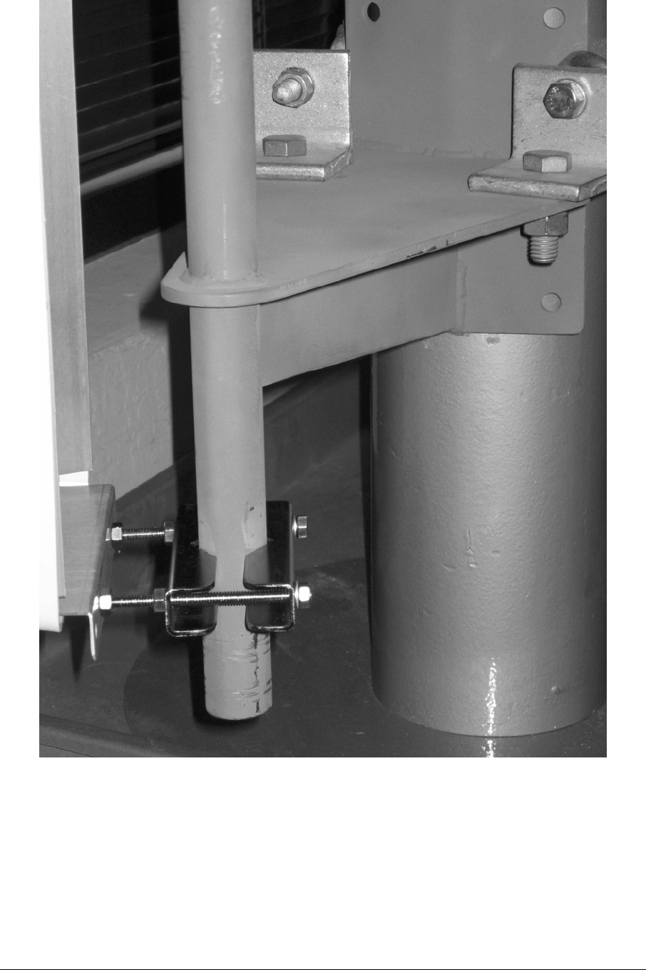
Figure 3-9: Pole Mount Kit and pipe mounted AP detail.
ARCXtend manual, August 2003 3-15