Arcwave AX315500 Point To Multipoint Wireless System User Manual Market Requirements
Arcwave, Inc. Point To Multipoint Wireless System Market Requirements
Arcwave >
Contents
- 1. User Manual 1 of 2
- 2. User Manual 2 of 2
User Manual 2 of 2
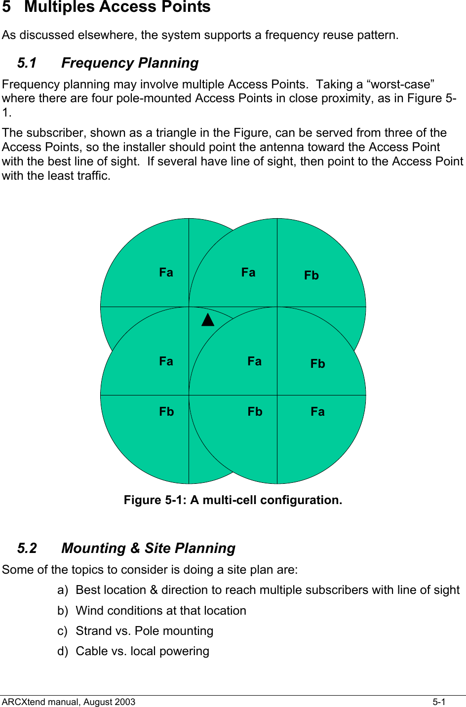
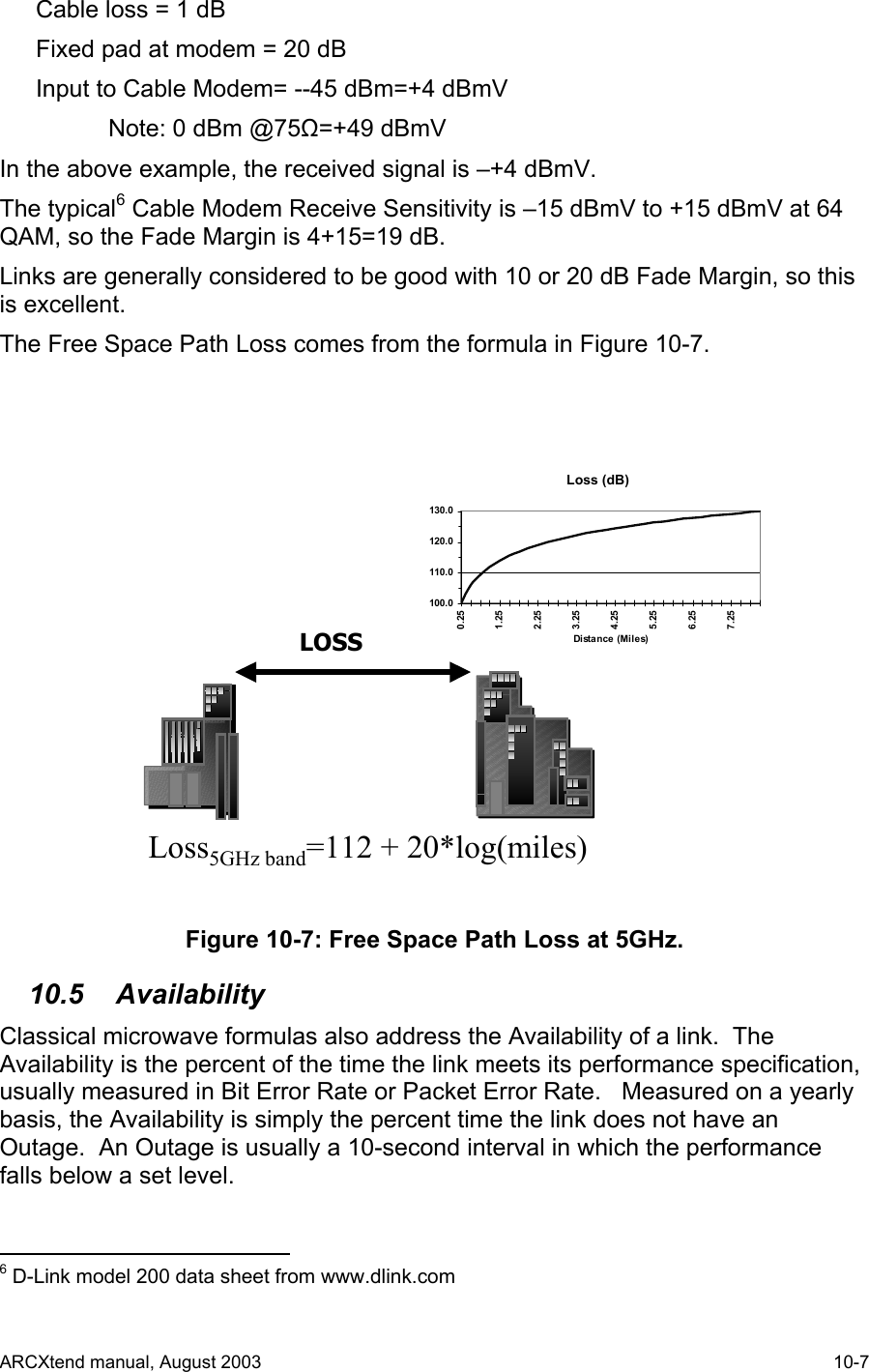
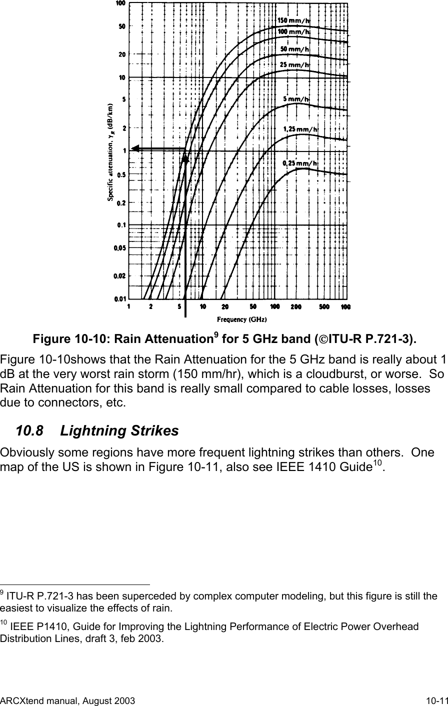
![Note that the Login command begins with an asterisk (*), and the Module’s address is repeated twice. Prior to Login, no Module is active, and no character echo back will be received on the PC. Example, to log into the Transmit Module (AR150): Type: *log0202 (all of which is hidden because it is not echoed) AR150TX [02] (this is what the Module sends to indicate successful login) The information above echoed by the addressed Module is: the Module type (AR150), the function (TX = Transmitter), and the hex address (02). The LOG command will automatically make any other active Module Quit (logout) if it was previously enabled. 4.3.2 TX Downstream Air Frequency The Downstream Air center Frequency is set within the 5.8 GHz band with the command: DA<nnnn>, where the frequency is in Megahertz. The DA command is acknowledged with an “initializing” message during the actual writing of internal processor registers, and the successful completion is acknowledged with the message displaying the new value. It must be given to both the TX Module and the DX Module. Example, to set the Downstream frequency to 5735 MHz: *log0202 [this typing is not echoed, not shown on the PC screen, the active module, seeing the login, will logout] AR150TX[02]>da5735 Initializing... DA Downstream Air Output 5735 MHz The Downstream Air frequency is the actual frequency used in the 5.8 GHz ISM band, as would be seen by a spectrum analyzer. It is received by the CPE outdoor transceiver which connects to the subscriber cable modem. The available 18 values are in the Section on Frequency Planning. IMPORTANT: Downstream Air Frequency must be set in BOTH the TX and the DX modules, separately. 4.3.3 TX Title The Title, or label, for the Access Point TX Module can be set. It can be up to 3 lines of alphanumeric text and keyboard printable ASCII symbols, with 32 characters per line. All three Modules can accept a Title. T<n><string>, where n = {0, 1, 2} Notice that there is no space between the single-digit line number <n> and the <string>. If there is one space, it is thrown away. Spaces in the title are OK. ARCXtend manual, August 2003 4-3](https://usermanual.wiki/Arcwave/AX315500.User-Manual-2-of-2/User-Guide-384492-Page-10.png)
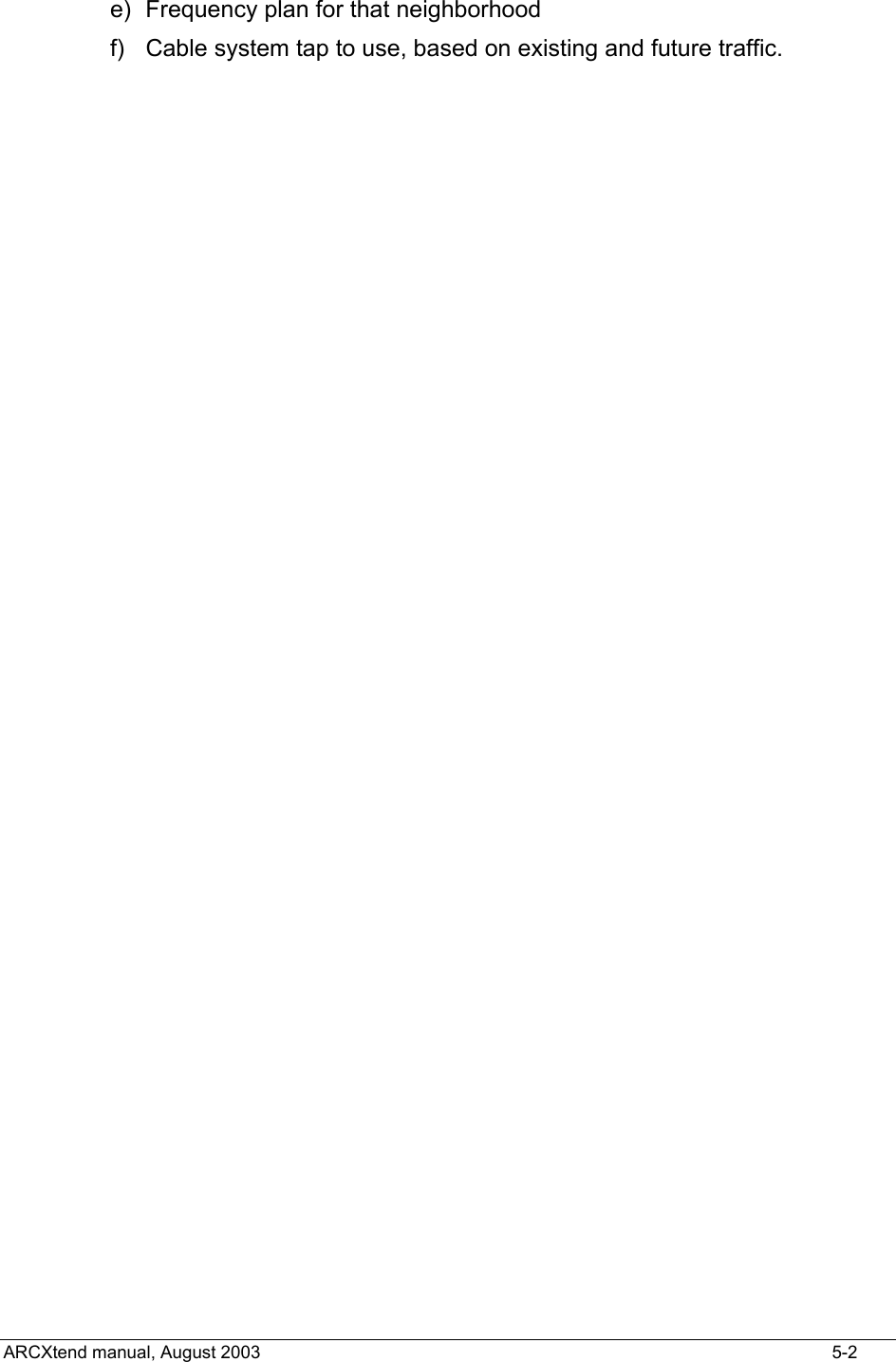
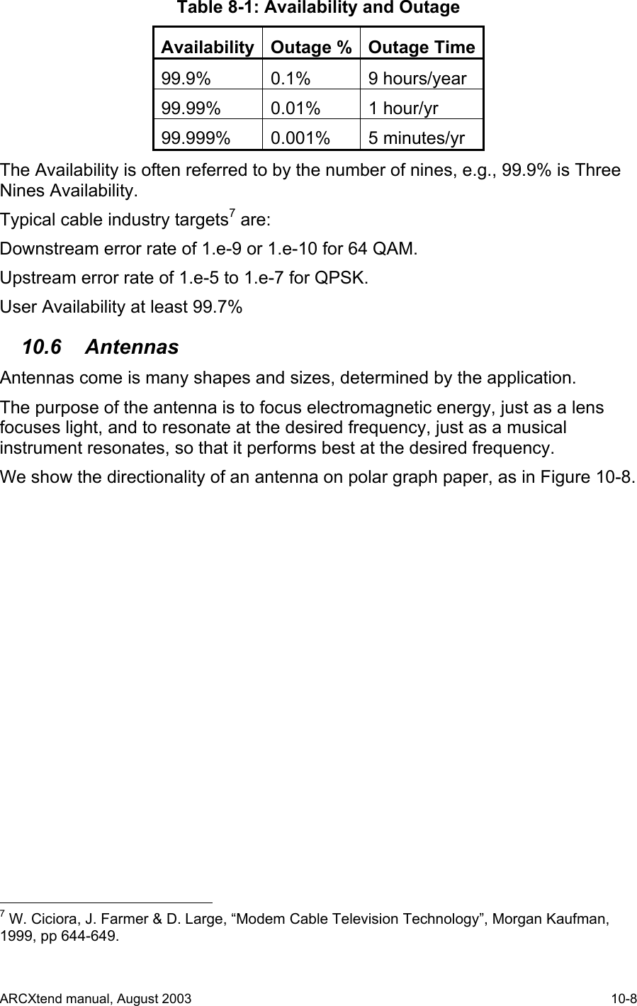
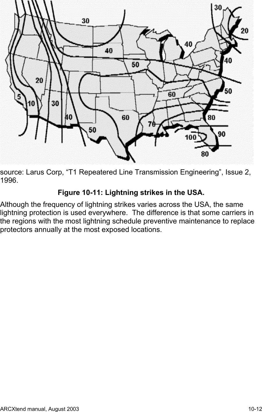
![A Title line ends with a carriage return. Example, to set the following title: *log0202 [this typing is not echoed, not shown on the PC screen] AR150 Tx [02] Enter up to 3 lines of text, beginning with T0, T1, or T2 T0 Pole #123 @ Main St. and 4th Ave T1Strand mounted T2 Pointing 300 degrees (west) 4.3.4 TX Banner Information A quick way to establish the basic information about an Access Point is to request the Banner Information. 1) Title 2) Downstream Air Frequency 3) Downstream enabled Command: B Example, look at transmitter parameters: *log0202 [this typing is not echoed, not shown on the PC screen] AR150TX[02]>b AR150 Transmitter Copyright (c) 2003 Arcwave, Inc. Software Build Aug 13 2003 20:46:38 DA Downstream Air Output 5729 MHz DE Downstream RF Enable NO ........ [factory default is series of dots] ........ ........ 4.3.5 TX Quit The Quit command will end the session with the device that was logged in. It is acknowledged with the phrase “logging off”. Example: Q Logging off ARCXtend manual, August 2003 4-4](https://usermanual.wiki/Arcwave/AX315500.User-Manual-2-of-2/User-Guide-384492-Page-11.png)
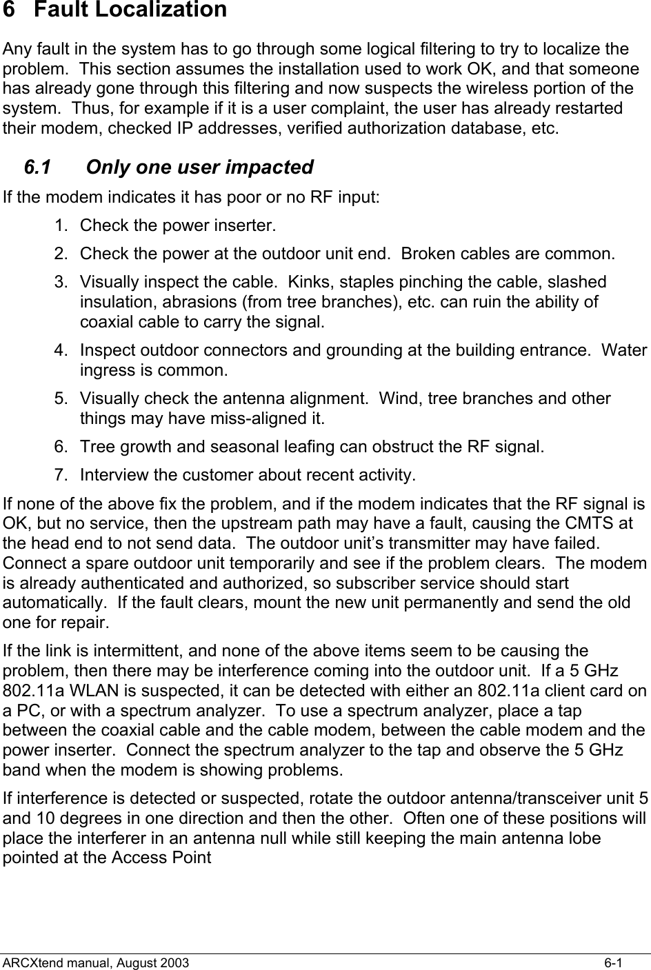
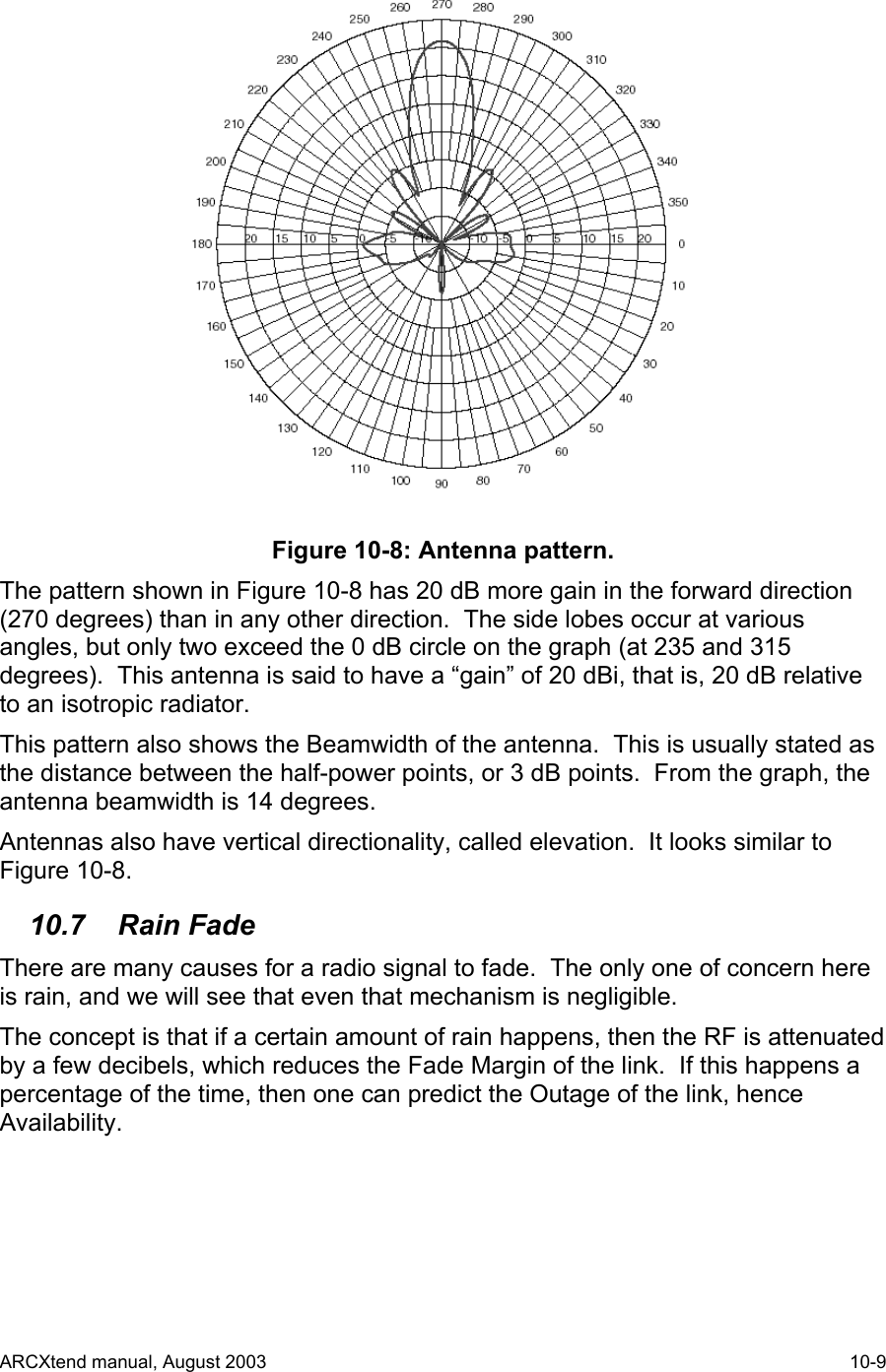
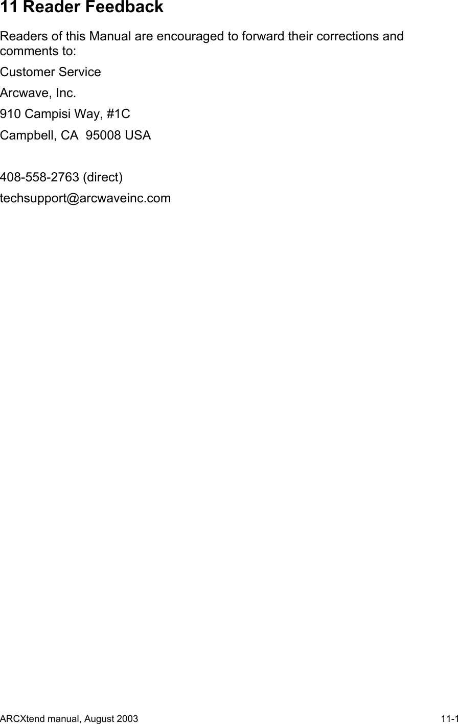
![4.3.6 TX Initialize The Initialize command forces the software to initialize, also called a Software Reboot or a Warm Start. The Access Point Module will return to its last saved settings. *log0202 AR150TX [02] Initializing… (no parameters are displayed) 4.3.7 TX Help The Help command will cause the active Module to generate a list of allowed system setup commands. Invalid or incomplete entries will generate a response that starts with a question mark and includes the valid entries that the CPU is expecting. Example: *log0202 [this typing is not echoed, not shown on the PC screen] AR150TX[02]>h List of commands... *LOGxxxx Log into card Q Quit I Initialize W[addr][data] Write EE Memory R Read EE Memory PI1xxxxxx PLL I,F,R,N Regs T[0-2] text Write a Title line S Status B Banner DAxxxx Downstream Air MHz DE[Y/N] Downstream Enable 4.3.8 TX Downstream Enable The Downstream Enable command allows RF power to be transmitted to the antenna. The parameter is YES or NO. YES is the normal state. NO is the factory default to prevent accidental transmissions at the wrong frequency. ARCXtend manual, August 2003 4-5](https://usermanual.wiki/Arcwave/AX315500.User-Manual-2-of-2/User-Guide-384492-Page-12.png)
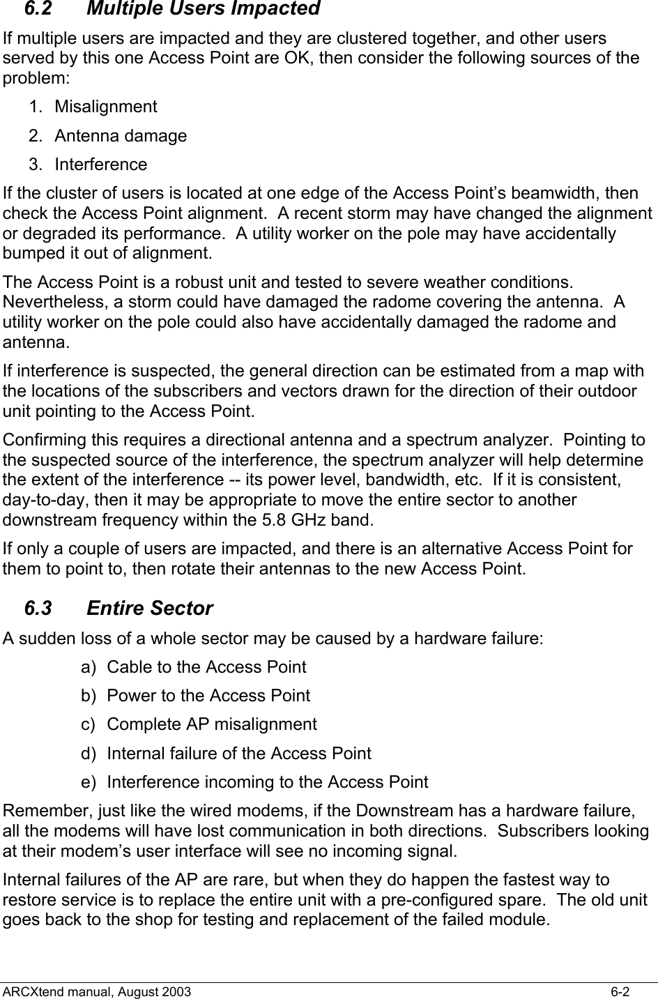
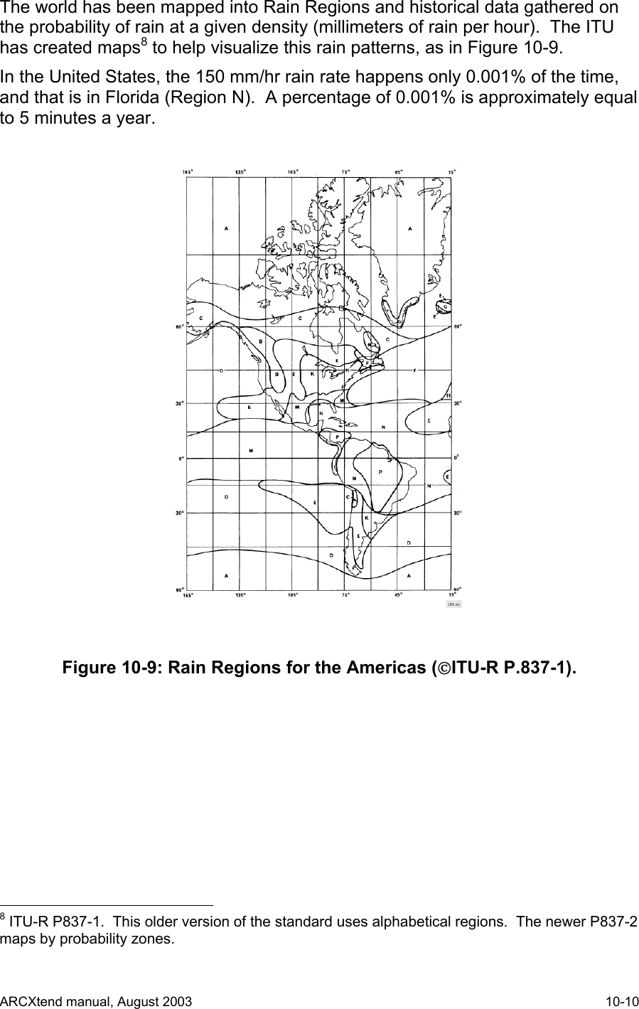
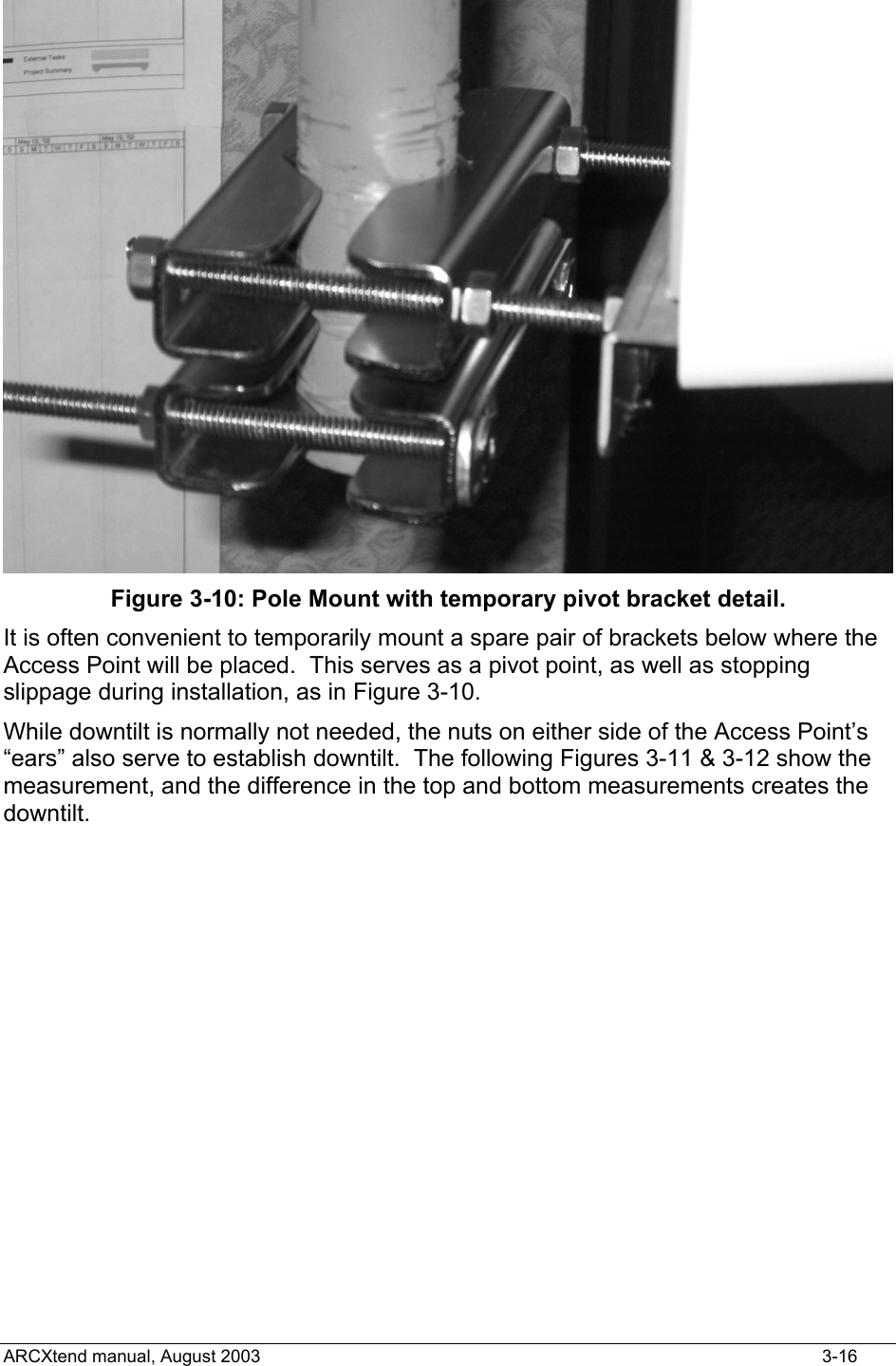
![The command is: DE<a>, where the alphabetic is Y (yes) or N (no) DEy DEn Example: AR150TX[02]>dey DE Downstream RF Enable YES 4.3.9 TX Transmit Defaults As shipped from the factory, the Transmit Module has the following default values: DE=no (i.e., disabled) DA=0000 MHz T0=….. T1=….. T2=….. 4.3.10 TX Status This is an engineering and manufacturing/repair command. It should not be used. 4.3.11 TX Read This is an engineering and manufacturing/repair command. It should not be used. 4.3.12 TX Screen Session The following series of examples contain actual screen captures to show a session with the Transmit Module might progress. This session includes Engineering/Mfg commands. *log0202 AR150TX[02]>b AR150 Transmitter Copyright (c) 2003 Arcwave, Inc. Software Build Aug 13 2003 20:46:38 DA Downstream Air Output 5729 MHz DE Downstream RF Enable NO ........ ........ ........ AR150TX[02]>da ? Value 1 ARCXtend manual, August 2003 4-6](https://usermanual.wiki/Arcwave/AX315500.User-Manual-2-of-2/User-Guide-384492-Page-13.png)
![? Valid Downstream Air Frequencies (MHz) are 5729 5735 5741 5747 5759 5765 5771 5777 5783 5789 5795 5807 5813 5819 5825 5831 5837 5843 LO STD: 5248 MMDS A: 5504 B: 5408 AR150TX[02]>da5735 Initializing... DA Downstream Air Output 5735 MHz AR150TX[02]>de ? Enable use deY(yes) or deN(no) AR150TX[02]>dey DE Downstream RF Enable YES AR150TX[02]>b AR150 Transmitter Copyright (c) 2003 Arcwave, Inc. Software Build Aug 13 2003 20:46:38 DA Downstream Air Output 5735 MHz DE Downstream RF Enable YES ........ ........ ........ AR150TX[02]>h List of commands... *LOGxxxx Log into card Q Quit I Initialize W[addr][data] Write EE Memory R Read EE Memory PI1xxxxxx PLL I,F,R,N Regs T[0-2] text Write a Title line S Status B Banner ARCXtend manual, August 2003 4-7](https://usermanual.wiki/Arcwave/AX315500.User-Manual-2-of-2/User-Guide-384492-Page-14.png)
![DAxxxx Downstream Air MHz DE[Y/N] Downstream Enable AR150TX[02]>i Initializing... AR150TX[02]>q Logging off 4.4 RX Command Line Interface Commands unique to the RX Module are: a) Upstream Air Frequency b) Upstream Enable c) Upstream Attenuate 4.4.1 RX Login This command is the same for the Receiver, but uses the Receive Module address (03 hex). 4.4.2 RX Title This command is the same for the Receiver. The information in the Title can be different for all three modules. 4.4.3 RX Quit This command is the same for the Receiver. 4.4.4 RX Upstream Frequency The AR105 RX Receive Module must have its Upstream receive air and cable frequencies set. The cable frequency is pre-assigned by the operator. Given the cable frequency, the received air frequency is a choice of two (lower and upper) air frequencies in the 5.250 to 5.350 GHz frequency band. Therefore once the cable upstream center frequency is set, the same command can set the air frequency. The command for Upstream Frequency is entered as decimal Megahertz plus an L (Low or lower) or H (High or upper) suffix. The command is: UF<nn.na>, where nn.n is the frequency in MHz and “a” is the alphabet L or H. ARCXtend manual, August 2003 4-8](https://usermanual.wiki/Arcwave/AX315500.User-Manual-2-of-2/User-Guide-384492-Page-15.png)
![Example, to set the Upstream RX to 6.4 MHz, with high 5.3 GHz band channel: *log0303 [this typing is not echoed, not shown on the PC screen] AR105RX[03]>uf6.4L Initializing... UF Upstream Frequency 6.4L MHz The Table in the Section on Frequency Planning shows the cable modem frequency and the corresponding 5.3GHz-band air frequencies. Note: MSO may have a different Upstream frequency. If so, select nearest one in the above table. The AX1255 will track the actual frequency. 4.4.5 RX Upstream Attenuation in dB The Cable System needs to receive a signal from the ARCXtend Access Point equivalent to what a standard wired cable modem at that same point in the CATV system would produce. To achieve this, the Upstream attenuation can be set to an appropriate value in decibels. The module contains a programmable attenuator, which can be controlled over a 30 dB range in 2 dB steps, thus providing a 30 dB range in gain. UdB<nn>, where nn is the value in decibels, and is an even number between 0 and 30. Example, to set the attenuation to 12 dB: *log0303 [this typing is not echoed, not shown on the PC screen] AR105RX[03]>udb12 UDB Upstream Attenuation 12 dB 4.4.6 RX Upstream Enable A method to enable or disable the wireless upstream signal path into the cable upstream channel. In normal operation this will be set to “Enable” which is the default. To disconnect the wireless upstream channel from the cable system upstream channel, set to “Disable”. In Disable mode all other module functions remain operating. The command is: UE<a>, where the alphabetical is y (yes) or n (no). UEY (Upstream Enable - YES) UEN (Upstream Enable - NO) The factory default is NO. Thus a unit inadvertently attached to a cable system without pre-configuration will NOT generate RF into the cable system, nor generate RF into the air. ARCXtend manual, August 2003 4-9](https://usermanual.wiki/Arcwave/AX315500.User-Manual-2-of-2/User-Guide-384492-Page-16.png)
![4.4.7 RX Banner Information The banner command for the RX Module is the same, but the information displayed is different. B 1) Title (3 lines) 2) Upstream EIA frequency 3) Upstream Attenuator setting 4) Upstream Enable (Y/N status) Example: AR105RX[03]>b AR105 Receiver Copyright (c) 2003 Arcwave, Inc. Software Build Aug 13 2003 20:10:11 UF Upstream Frequency 19.2L MHz UE Upstream RF Enable YES UDB Upstream Attenuation 12 dB ........ ........ ........ 4.4.8 RX Module Help The HELP command for the Receive Module AR105 delivers the following list of RX commands: Login Quit Initialize Write Read Phase Lock Loop settings Title Status Banner Upstream Frequency Upstream Enable Upstream Attenuator ARCXtend manual, August 2003 4-10](https://usermanual.wiki/Arcwave/AX315500.User-Manual-2-of-2/User-Guide-384492-Page-17.png)
![Example: AR105RX[03]>h List of commands... *LOGxxxx Log into card Q Quit I Initialize W[addr][data] Write EE Memory R Read EE Memory PI1xxxxxx PLL I,F,R,N Regs T[0-2] text Write a Title line S Status B Banner UFxx.x[H/L] Upstream Freq HI/LO UE[Y/N] Upstream Enable Y/N UDBxx Upstream Attenuation 4.4.9 RX Module Status This is an engineering and manufacturing/repair command. It should not be used. 4.4.10 RX Read This is an engineering and manufacturing/repair command. It should not be used. 4.4.11 RX Module Session *log0303 AR105RX[03]>b AR105 Receiver Copyright (c) 2003 Arcwave, Inc. Software Build Aug 13 2003 20:10:11 UF Upstream Frequency 19.2L MHz UE Upstream RF Enable YES UDB Upstream Attenuation 12 dB ........ ........ ........ AR105RX[03]>h *LOGxxxx Log into card ARCXtend manual, August 2003 4-11](https://usermanual.wiki/Arcwave/AX315500.User-Manual-2-of-2/User-Guide-384492-Page-18.png)
![Q Quit I Initialize W[addr][data] Write EE Memory R Read EE Memory PI1xxxxxx PLL I,F,R,N Regs T[0-2] text Write a Title line S Status B Banner UFxx.x[H/L] Upstream Freq HI/LO UE[Y/N] Upstream Enable Y/N UDBxx Upstream Attenuation AR105RX[03]>b AR105 Receiver Copyright (c) 2003 Arcwave, Inc. Software Build Aug 13 2003 20:10:11 UF Upstream Frequency 19.2L MHz UE Upstream RF Enable YES UDB Upstream Attenuation 12 dB ........ ........ ........ AR105RX[03]>uf ? Use Frequency plus L,H (ie 6.4L) 6.4 9.6 12.8 16.0 19.2 22.4 25.6 28.8 32.0 35.2 38.4 41.6 44.8 48.0 AR105RX[03]>uf6.4l Initializing... UF Upstream Frequency 6.4L MHz AR105RX[03]>ue ? Enable use ueY(yes) or ueN(no) ARCXtend manual, August 2003 4-12](https://usermanual.wiki/Arcwave/AX315500.User-Manual-2-of-2/User-Guide-384492-Page-19.png)
![AR105RX[03]>uey UE Upstream RF Enable YES AR105RX[03]>udb ? Attenuator: 0 to 30 dB (2dB steps) AR105RX[03]>udb12 UDB Upstream Attenuation 12 dB AR105RX[03]>b AR105 Receiver Copyright (c) 2003 Arcwave, Inc. Software Build Aug 13 2003 20:10:11 UF Upstream Frequency 6.4L MHz UE Upstream RF Enable YES UDB Upstream Attenuation 12 dB ........ ........ ........ AR105RX[03]>uen UE Upstream RF Enable NO AR105RX[03]> 4.5 DX Command Line Interface The Digital Cable Extender (DX) Module commands are described in this section. Commands unique to the DX Module are: a) Downstream Air Frequency b) CATV Channel 4.5.1 DX Downstream Help The DX HELP command produces the following list of commands: Login Quit Initializie ARCXtend manual, August 2003 4-13](https://usermanual.wiki/Arcwave/AX315500.User-Manual-2-of-2/User-Guide-384492-Page-20.png)
![Write Read Phase Lock Loop Title Status Banner Downstream Cable EIA Downstream Air AGC control DAC output MT control Many of these above commands are for Engineering and Manufacturing/Repair use only. Example: AR250DX[01]>h List of commands... *LOGxxxx Log into card Q Quit I Initialize W[addr][data] Write EE Memory R Read EE Memory PI1xxxxxx PLL I,F,R,N Regs T[0-2] text Write a Title line S Status B Banner DCExx CATV EIA Input Chan DAxxxx Downstream Air MHz Ax AGC control Vcddd DAC Output M[reg][data] MT control 4.5.2 DX Quit The DX Quit command is the same. ARCXtend manual, August 2003 4-14](https://usermanual.wiki/Arcwave/AX315500.User-Manual-2-of-2/User-Guide-384492-Page-21.png)
![4.5.3 DX Downstream Cable Channel The Downstream Cable EIA (DCE) Channel is the channel on which the DOCSIS cable modem downstream signal is being sent from the CMTS at the head end. It is set in the ARCXtend Access Point with the standard EIA channel numbers. *DCE<nnn>, where nnn is an EIA channel number from 23 to 94 and 100 to 138. Note: In the EIA standard, channels 94 and 100 are adjacent, so there is no gap in frequency. The system response to the command is the word “initializing” followed by a series of internal registers that the CPU is writing to. Successful completion is noted by displaying the result achieved, plus the actual ARCXtend center frequency for that channel. The corresponding 6 MHz channel center frequency from the cable-to-AX1255 and from AX3155-to-modem is given in the Table below. Example, to set the Downstream Cable EIA Channel to channel 23: *log0101 [this typing is not echoed, not shown on the PC screen, the active module, seeing the login, will logout] AR250DX[01]>dce23 Initializing... MT2050 Write Reg 0x01 Data 0xAD MT2050 Write Reg 0x02 Data 0x1C MT2050 Write Reg 0x03 Data 0xA8 MT2050 Write Reg 0x04 Data 0x00 MT2050 Write Reg 0x05 Data 0x63 MT2050 Write Reg 0x06 Data 0x10 MT2050 Write Reg 0x08 Data 0x29 MT2050 Write Reg 0x0A Data 0x05 MT2050 Write Reg 0x0F Data 0x0F MT2050 Write Reg 0x10 Data 0x24 DCE CATV Input US Channel 23 (219 MHz) 4.5.4 DX Downstream Air Frequency Both the TX and DX module must also be programmed with the DA command and the same frequency. The command context is the same as for the TX module, but logging into the DX Module. ARCXtend manual, August 2003 4-15](https://usermanual.wiki/Arcwave/AX315500.User-Manual-2-of-2/User-Guide-384492-Page-22.png)
![The response to the DA command is “initializing” followed by a list of registers that the CPU is writing. Successful completion is displayed by the actual frequency achieved as “air output”. Example: AR250DX[01]>da5789 Initializing... MT2050 Write Reg 0x01 Data 0xAD MT2050 Write Reg 0x02 Data 0x1C MT2050 Write Reg 0x03 Data 0xA8 MT2050 Write Reg 0x04 Data 0x00 MT2050 Write Reg 0x05 Data 0x63 MT2050 Write Reg 0x06 Data 0x10 MT2050 Write Reg 0x08 Data 0x29 MT2050 Write Reg 0x0A Data 0x05 MT2050 Write Reg 0x0F Data 0x0F MT2050 Write Reg 0x10 Data 0x24 DA Air Output 5789 MHz (250->150 IF 461 MHz LO: 505 MHz) 4.5.5 DX Initialization The DX INITIALIZE command resets the software and rewrites the registers. The command is: i The response is the word “initializing” followed by a series of registers being written. Successful completion is indicated by the prompt: AR250DX[01] Example: AR250DX[01]>i Initializing... MT2050 Write Reg 0x01 Data 0xAD MT2050 Write Reg 0x02 Data 0x1C MT2050 Write Reg 0x03 Data 0xA8 MT2050 Write Reg 0x04 Data 0x00 MT2050 Write Reg 0x05 Data 0x63 MT2050 Write Reg 0x06 Data 0x10 MT2050 Write Reg 0x08 Data 0x29 ARCXtend manual, August 2003 4-16](https://usermanual.wiki/Arcwave/AX315500.User-Manual-2-of-2/User-Guide-384492-Page-23.png)
![MT2050 Write Reg 0x0A Data 0x05 MT2050 Write Reg 0x0F Data 0x0F MT2050 Write Reg 0x10 Data 0x24 AR250DX[01]> 4.5.6 DX Status This is an engineering and manufacturing/repair command. It should not be used. 4.5.7 DX AGC Control This is an engineering and manufacturing/repair command. It should not be used. 4.5.8 DX MT Control This is an engineering and manufacturing/repair command. It should not be used. 4.5.9 DX DAC Output Read Command This is an engineering and manufacturing/repair command. It should not be used. 4.5.10 DX Read This is an engineering and manufacturing/repair command. It should not be used. 4.5.11 DX Write This is an engineering and manufacturing/repair command. It should not be used. 4.5.12 DX Screen Session The following series of examples contain actual screen captures to show how the DX Module AX250 responds to various input. *log0101 AR250DX[01]>h List of commands... *LOGxxxx Log into card Q Quit I Initialize W[addr][data] Write EE Memory R Read EE Memory PI1xxxxxx PLL I,F,R,N Regs T[0-2] text Write a Title line S Status B Banner DCExx CATV EIA Input Chan ARCXtend manual, August 2003 4-17](https://usermanual.wiki/Arcwave/AX315500.User-Manual-2-of-2/User-Guide-384492-Page-24.png)
![DAxxxx Downstream Air MHz Ax AGC control Vcddd DAC Output M[reg][data] MT control AR250DX[01]>b Digital Cable Extender Copyright (c) 2003 Arcwave, Inc. Software Build Aug 13 2003 20:50:47 DCE CATV Input US Channel 0 ( 0 MHz) DA Air Output 0 MHz (250->150 IF 0 MHz LO: 44 MHz) ........ ........ ........ AR250DX[01]>dce ? Value 1 ? Valid CATV Input Channels are 23-94 and 100-138 AR250DX[01]>dce23 Initializing... MT2050 Write Reg 0x01 Data 0xAD MT2050 Write Reg 0x02 Data 0x1C MT2050 Write Reg 0x03 Data 0xA8 MT2050 Write Reg 0x04 Data 0x00 MT2050 Write Reg 0x05 Data 0x63 MT2050 Write Reg 0x06 Data 0x10 MT2050 Write Reg 0x08 Data 0x29 MT2050 Write Reg 0x0A Data 0x05 MT2050 Write Reg 0x0F Data 0x0F MT2050 Write Reg 0x10 Data 0x24 DCE CATV Input US Channel 23 (219 MHz) AR250DX[01]>da ? Value 1 ARCXtend manual, August 2003 4-18](https://usermanual.wiki/Arcwave/AX315500.User-Manual-2-of-2/User-Guide-384492-Page-25.png)
![? Valid Downstream Air Frequencies (MHz) are 5729 5735 5741 5747 5759 5765 5771 5777 5783 5789 5795 5807 5813 5819 5825 5831 5837 5843 AR250DX[01]>da5789 Initializing... MT2050 Write Reg 0x01 Data 0xAD MT2050 Write Reg 0x02 Data 0x1C MT2050 Write Reg 0x03 Data 0xA8 MT2050 Write Reg 0x04 Data 0x00 MT2050 Write Reg 0x05 Data 0x63 MT2050 Write Reg 0x06 Data 0x10 MT2050 Write Reg 0x08 Data 0x29 MT2050 Write Reg 0x0A Data 0x05 MT2050 Write Reg 0x0F Data 0x0F MT2050 Write Reg 0x10 Data 0x24 DA Air Output 5789 MHz (250->150 IF 461 MHz LO: 505 MHz) AR250DX[01]>i Initializing... MT2050 Write Reg 0x01 Data 0xAD MT2050 Write Reg 0x02 Data 0x1C MT2050 Write Reg 0x03 Data 0xA8 MT2050 Write Reg 0x04 Data 0x00 MT2050 Write Reg 0x05 Data 0x63 MT2050 Write Reg 0x06 Data 0x10 MT2050 Write Reg 0x08 Data 0x29 MT2050 Write Reg 0x0A Data 0x05 MT2050 Write Reg 0x0F Data 0x0F MT2050 Write Reg 0x10 Data 0x24 AR250DX[01]>q ARCXtend manual, August 2003 4-19](https://usermanual.wiki/Arcwave/AX315500.User-Manual-2-of-2/User-Guide-384492-Page-26.png)