Arcwave FX501000 Point-to-Point Wireless Internet System User Manual 451977D5 4B3B 288679
Arcwave, Inc. Point-to-Point Wireless Internet System 451977D5 4B3B 288679
Arcwave >
Users Manual

Arcwave’s ARCXtend MetroE FX5010
Wireless Plant Extension Solution
User Guide
P/N: 920-20010-001 Rev. A
100 Albright Way, Suite A
Los Gatos, CA 95032 USA,
Phone: 408-558-2300
www.arcwaveinc.com
©
2
006
2 of 47
About this document
This guide is designed familiarize you with the ARCXtend MetroE Wireless Plant Extension
solution (WPE) solution and to provide basic instructions on the planning, provisioning,
verification, monitoring and expansion of MetroE deployments.
It is designed to be used on conjunction with the ARCView Mesh Management Software User
Guide which provides detailed information on the
Note
The software used on the ARCXtend MetroE wireless plant extension solution supports not only
point to point and point to multipoint but also mesh network topologies. The ARCView network
management software uses the term ‘‘mesh’ for all configurations. For consistency this guide will
also use the term mesh to describe any configuration of two or more MetroE nodes. A node refers
to one radio which for the purpose of this guide is one MetroE radio. Again we will use node to
refer to an MetroE radio for consistency with ARCView.
Revision History
Related Documents
The following documents provide additional information about the ARCXtend HSD WPE solution:
• ARCView Mesh Manaegment Sofwtare User Guide
• ARCXtend MetroE MIB (.txt)
Feedback
We welcome your feedback on Arcwave documentation. This includes feedback on structure,
content, accuracy, or completeness of our documents, and any other comments you may have.
Please send your comments to marketing@arcwaveinc.com.
Trademarks
Arcwave and the Stylized Arcwave Logo, ARCXtend, ARCXtend MetroE, ARCView and
ARCViewPro are trademarks of Arcwave. Other product/service names are the property of their
owners.
ISSUE # AUTHOR CHECK OUT CHECK IN COMMENTS
1.0 CM JUNE 7, 2006 FOR BETA RELEASE

3 of 47
Notices
The information in this publication is subject to change without notice. Arcwave shall not be liable
for technical or editorial errors or omissions nor for any damages resulting from the use of this
material.
U.S. Federal Communication Commission (FCC) Notification
This device complies with part 15 of the U. S. FCC Rules and Regulations and which is subject to
the following two conditions: (1) This device may not cause harmful interference, and (2) This
device must accept any interference received, including interference that may cause undesired
operation.
This equipment has been tested and found to comply with the limits for a Class B digital device,
pursuant to Part 15 of the U.S. FCC Rules. These limits are designed to provide reasonable
protection against harmful interference in a residential installation. This equipment generates,
uses, and can radiate radio-frequency energy and, if not installed and used in accordance with
these instructions, may cause harmful interference to radio communications. If this equipment
does cause harmful interference to radio or television reception, which can be determined by
turning the equipment on and off, the user is encouraged to correct the interference by one or
more of the following measures:
Increase the separation between the affected equipment and the unit;
• Connect the affected equipment to a power outlet on a different circuit from that which the
receiver is connected to;
• Consult the dealer and/or experienced radio/TV technician for help.
Part 15, Section 15.21 Warning
Changes or modifications not expressly approved by Arcwave, Inc. could void the user's authority
to operate the equipment. FCC IDs Numbers are listed below:
FCC Identifier: PLRFX501000
RF Safety Warning
To ensure compliance with FCC recommended General Population/Uncontrolled exposure limits
the ARCXtend MetroE radio must be installed at a minimum of one foot from areas frequented by
the general population.
To ensure compliance with FCC recommended Occupational/Controlled exposure limits, field
engineers and technicians should maintain a minimum working distance of six inches, as
measured from the front of the radio to the front of their bodies. For working distance inside six
inches, RF exposure should be limited to an average of 30 minutes at a time. All Arcwave
equipment, however, has been designed to allow installation and maintenance at a range well
within FCC RF exposure levels.

4 of 47
Table of Contents
The ARCXtend MetroE Wireless Plant Extension Solution 5
The ARCXtend MetroE Solutions 10
Planning a MetroE Deployment 12
ARCView Mesh Management Software for MetroE Nodes 14
Installing ARCView 16
Using ARCView 18
Quick Mesh Check 20
Country Code Setting 21
Customizing Your Mesh Network 22
Configuring Individual Nodes 27
Installing Nodes 33
Aligning Nodes 37
Link Verification 38
Retorting Default Settings 44
Appendix A: Arcwave Support 45
Appendix B: FX5010 Technical Specification 46
5 of 47
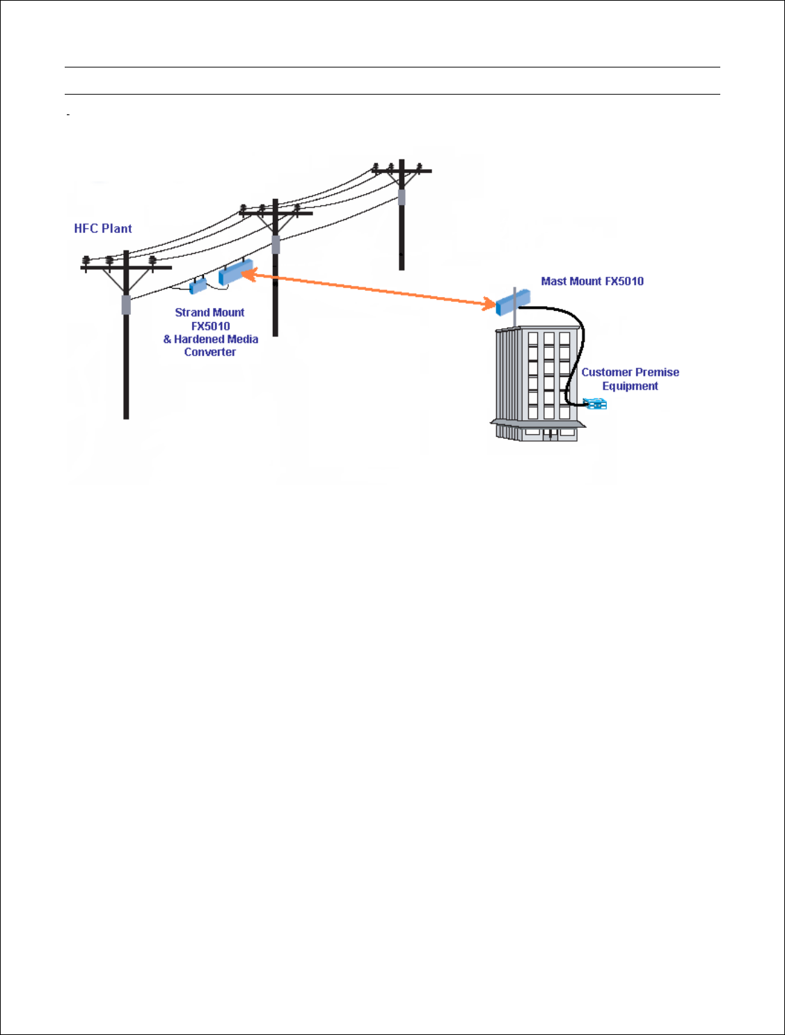
The ARCXtend MetroE Wireless Plant Extension Solution
The ARCXtend MetroE wireless plant extension solution creates a transparent wireless Ethernet
bridge between a cable operator’s fiber network and small and medium-sized business customers’
sites supporting delivery of high value Ethernet services without the delay and expense of a fiber
extension.
A MetroE solution consists of a pair of fully integrated outdoor radios, called nodes, which
together create a point-to- point wireless link that transparently bridges the fiber network and
customer LANs. The MetroE node can be strand; pole or mast mounted and powered using IEEE
802.3af standard Power over Ethernet (POE) or 60 or 90 VAC coaxial cable line-powering. It
includes a weatherized RJ-45 Fast Ethernet port for enabling direct, all outdoor connection to aerial
fiber plants via hardened media converters or for connecting to standard customer premise
equipment including switches, routers, firewalls and network interface devices. The two radios
together form a low latency (less than 2 milliseconds one way), high availability point to point
wireless link operating in the license-free 5 GHz band with a sustained point-to-point throughput of
up to 32 mbps at a range of up to 3 miles and up to 99.999% link availability.
The major elements of the MetroE solution:
Wireless Interface
The MetroE utilizes a 20 MHz wireless channel located anywhere in the license free spectrum 5725
to 5850 MHz ISM (Industrial, Scientific and Medical) unlicensed band. With so much wireless
spectrum and only a single wireless channel, interference-free operation is virtually assured. The
FX5010 utilizes orthogonal frequency division multiplexing (OFDM), forward error correction, and
adaptive modulation technology to support operation of up to 54Mbps raw data rates with near
line-of-site coverage. Near line-of-site coverage capability ensures optimal link performance in real
world deployment conditions.

6 of 47
Ethernet Bridging Protocol
The MetroE uses a low-latency; low overhead time division duplexing protocol TDD protocol to
achieve a true 32 mbps aggregate Ethernet throughput and 10 mbps symmetric throughput
making it an ideal access solution for a typical SMB looking for a lower cost, higher bandwidth
alternative to DSL or nxT1 service. It is fully transparent to Ethernet data frames, Layer 2 Control
Processing packets and 802.1q Trunking, QinQ (802.1q inside 802.1q), MPLS VPN and UTI/L2TPV3
(encapsulate one Ethernet packet in another Ethernet packet with a tunneling header) traffic
providing support for all standard Metro Ethernet Line (ELS) and LAN (E-LAN) services.
Security
The MetroE provide end-to-end traffic encryption using Advanced Encryption Standard at 128 or
256 bits. Access control is provided by MAC address filtering on either an explicit Allow or Deny
basis. VLANs, which segment traffic across the links, add yet another layer of security.
Physical
The MetroE is a fully hardened outdoor radio purpose built to meet cable industry physical and
environmental specifications ensuring rapid deployment and trouble-free operation. The radio
operates over the cable industry standard -40 to 60C outdoor temperature range and is fully
waterproof and UV (ultraviolet light) and corrosion resistant. The 60 --- 90 VAC line-power
connection meets applicable SCTE (Society of Cable Telecommunications Engineers)
specifications for F connectors, torque requirements, surge protection and ESD immunity. The
power supply, also used in our widely deployed ARCXtend HSD product, is proven compatible
with 60 and 90VAC coaxial line powering.
The strands mount bracket, taken from the field proven ARCXtend HSD product and developed
with direct input from cable industry engineers, features SCTE compliant mounting hardware and
one-person installation and alignment. The mast mount bracket for customer site deployment
enables installation using the readily available and low cost microwave and satellite dish mounting
kits.
Finally the MetroE has been certified to meet applicable FCC (Federal Communications
Commission) radio standards for unlicensed band operation and emissions.
Management
ARCView Mesh Management Software provides real-time monitoring and comprehensive and
centralized management of one or more ARCXtend MetroE links. An intuitive graphical user
interface affords "point-and-click" control settings for security, traffic prioritization, radio behavior
and internetworking.
The MetroE also features SNMP accessible MIBs for equipment, link and Ethernet service
monitoring supporting management of commercial service level agreements using existing
network and service management systems.
Product Features
Below are descriptions of some of the MetroE wireless mesh network’s features.

7 of 47
Mesh Management Using ARCView Software
ARCView™ mesh management software provides live monitoring, as well as local and remote
management of MetroE wireless mesh networks. The software features an intuitive graphical user
interface and provides complete access to all mesh and individual node settings, including
security, VLANs, traffic prioritization, radio power controls, and Network Gateway Interconnects.
Live monitoring features include mesh and node statistics and a graphical view that uses node
icons to indicate active connections. Users can also import graphics of floor plans or maps. The
icons for each node can be moved over the graphics to show where they are physically located.
Security
The MetroE ODU mesh network includes several layers of security, including AES key and WEP
encryption.
AES (Advanced Encryption Standard) encryption can be used to protect data exchanged between
any two nodes in a wireless mesh. When AES encryption is enabled for a wireless mesh, all
payload data leaving the nodes in the mesh is encrypted using 128- or 256-bit keys. The data
remains encrypted as it passes through the intermediate nodes and is only decrypted at the end
node where it leaves the mesh network. This provides end-to-end security for the customer data
passing through the MetroE ODU wireless mesh.
WEP (Wired Equivalent Policy) supports 40/64- and 104/128-bit encryption to protect all traffic on
the mesh, including routing and management traffic. This can be used to protect traffic over the
wireless links.
For additional security, a proprietary mesh protocol prevents non-MetroE ODU devices from
participating on the mesh. Secure network access can also be provided for applications that do not
allow Wi-Fi client services by connecting computers to the mesh directly using cables connected to
the Ethernet ports on a MetroE ODU node.
Packet Filtering
MetroE ODU nodes can filter packets based upon the MAC address of the traffic. You can configure
each Ethernet port to deny or permit access for traffic coming from or to specific devices
(identified by the devices’ MAC addresses).
VLANs
The MetroE ODU mesh network includes support for virtual local area networks (VLANs) to enable
traffic to be separated into smaller groups and application-specific LANs. VLANs allow small
groups of users to operate within their own private space on the mesh, and they can also improve
mesh performance by directing traffic onto specific VLAN routes. The MetroE ODU mesh supports
802.1Q VLAN tagging of packets entering and exiting the mesh.
You can configure each Ethernet port to operate as part of a VLAN. A MetroE ODU wireless mesh
can support multiple VLANs. You can assign ports to different VLANs. Only ports belonging to the
same VLAN can switch traffic among themselves. You can create up to 16 logically separated
VLAN networks within a single mesh. The MetroE ODU mesh also supports VLAN trunks.

8 of 47
Traffic Prioritization
The MetroE ODU system provides three traffic prioritization levels (Low, Medium, or High) to
prioritize traffic on the mesh. This helps ensure that certain types of traffic requiring high
throughput or continuous service, such as voice, take precedence over other forms of traffic. Every
port on every node on the mesh can be set to any of these three priority levels.
Network Gateway Interconnects
The MetroE ODU mesh network allows multiple mesh portals for efficient access to external
network services, such as the Internet. This capability enables high throughput and redundancy for
external services and optimizes the transport of traffic though the mesh. MetroE ODU mesh nodes
can also be assigned to specific portal groups (called ‘‘Gateway Groups’’) to further increase the
efficiency of each portal. You configure portals by defining Network Gateway Interconnects (NGIs).
Each Gateway Group can support up to 16 NGIs and you can define up to 8 Gateway Groups. Each
node on the mesh can have only one Gateway Group interconnect. Gateway groups are not
required when connecting to different network domains or if only one NGI is being used.
The NGI feature provides both load balancing and redundancy when accessing various network
services. This helps provide better wireless mesh data throughput because it allows packets to
enter and exit the wireless mesh at the entry/exit point closest to the packet’s destination, thereby
conserving wireless bandwidth and reducing the number of hops required to reach the desired
destination.
Radio Settings
MetroE ODU wireless mesh nodes are FCC approved for operation only in the 5.8 GHz band. The
selected radio mode is applied to the entire wireless mesh. You can use the ARCView
management software to display and modify the radio transmit power level for each node.
Speed and Duplex Settings
You can configure the Ethernet port for 10 or 100 Mbps speed or for automatic speed negotiation.
Network traffic between a MetroE ODU node and devices connected to its Ethernet port travels up
to full wire rate (10 or 100 Mbps). The port can also be configured for full- or half-duplex operation.
In addition, you can enable and disable individual ports.
The Ethernet ports support auto MDIX, which allows you to use either straight-through or
crossover cables to connect the MetroE ODU node to other devices.
Transmit Power Control
You can display and modify the radio TX power level on a per node basis utilizing the ARCView™
management software. The maximum power (that is, 100%) is a factory-configured value that is
unique to each country of operation, each channel of operation, and each antenna configuration,
and has been determined to be within an authorized limit. This value cannot be changed. However,
using the ARCView software, a mesh administrator can set any node to operate at a reduced
percentage of this maximum power (for example, 75%, 50%, or 25%; the default setting is 75%).
The administrator can restore the MetroE ODU node to its approved maximum power by setting
the power level back to 100%.

9 of 47
Note: Transmit power control adjustments affect the node radio, so care must be exercised when
making adjustments on an existing network, as the reduced power level may cause the node to
lose connectivity with other mesh nodes.
Note: Adjusting the power incorrectly could have an adverse effect on proper mesh operations.
If you are not sure what the power should be adjusted to, it is best to leave it at its default
configuration. If you need additional technical assistance, please contact your Arcwave dealer.
10 of 47
The ARCXtend MetroE Solutions
FX5010-ODU Point-to-Point Solution
The FX5010-ODU is a self-contained weather-protected, strand mountable radio providing a point-
to-point wireless Ethernet connection between a fiber plant and a customer Local Area Network.
The FX5010-ODU includes an integrated transceiver, 20º directional antenna, 60 to 90 VAC power
supply and Power over Ethernet Source (PSE) for powering third-party media converters. It comes
in four different configurations based on mounting and powering:
Configurations
Model Mounting Bracket Power over Ethernet
FX5010-ODU-VM-PSE Mast Power Sourcing (PSE; delivers
power)
FX5010-ODU-VM-PD Mast Powered (PD; accepts power)
FX5010-ODU-SM-PSE Strand Power Sourcing (PSE; delivers
power)
FX5010-ODU-SM-PD Strand Powered (PD; accepts power)
Included Accessories
• FX5010-CD, documentation CD
Optional Accessories
• FX5010-RJ45-1 one meter RJ-45 cable, model number for interconnecting the ODU to
hardened media converters marketed by PCT and Aurora
• FX5010-PS-48V 48 VDC Power-Over-Ethernet Injector and Power Supply
• FX5010-SS-CAT5 CAT5 Surge Suppressor
• S3-SM-EXT-4 S3 Hub Style, Strand Mount Bracket with 4" cable clearance, bracket is
shipped separately
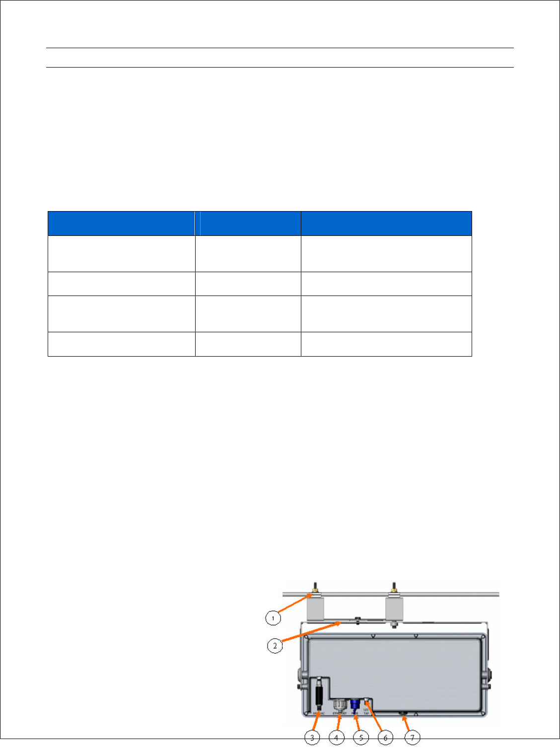
Connections
The following illustration shows the rear of
the ODU and identifies the connections and
strand mount bracket components:
(1) Strand Mounting Clamps
Cable industry standard clamps for
mounting the hub to the strand cable.
11 of 47
(2) Strand Mount Alignment Brackets
Mechanically adjustable horizontal and
vertical hub alignment brackets for aligning
the hub’s integrated antenna to the desired
coverage area.
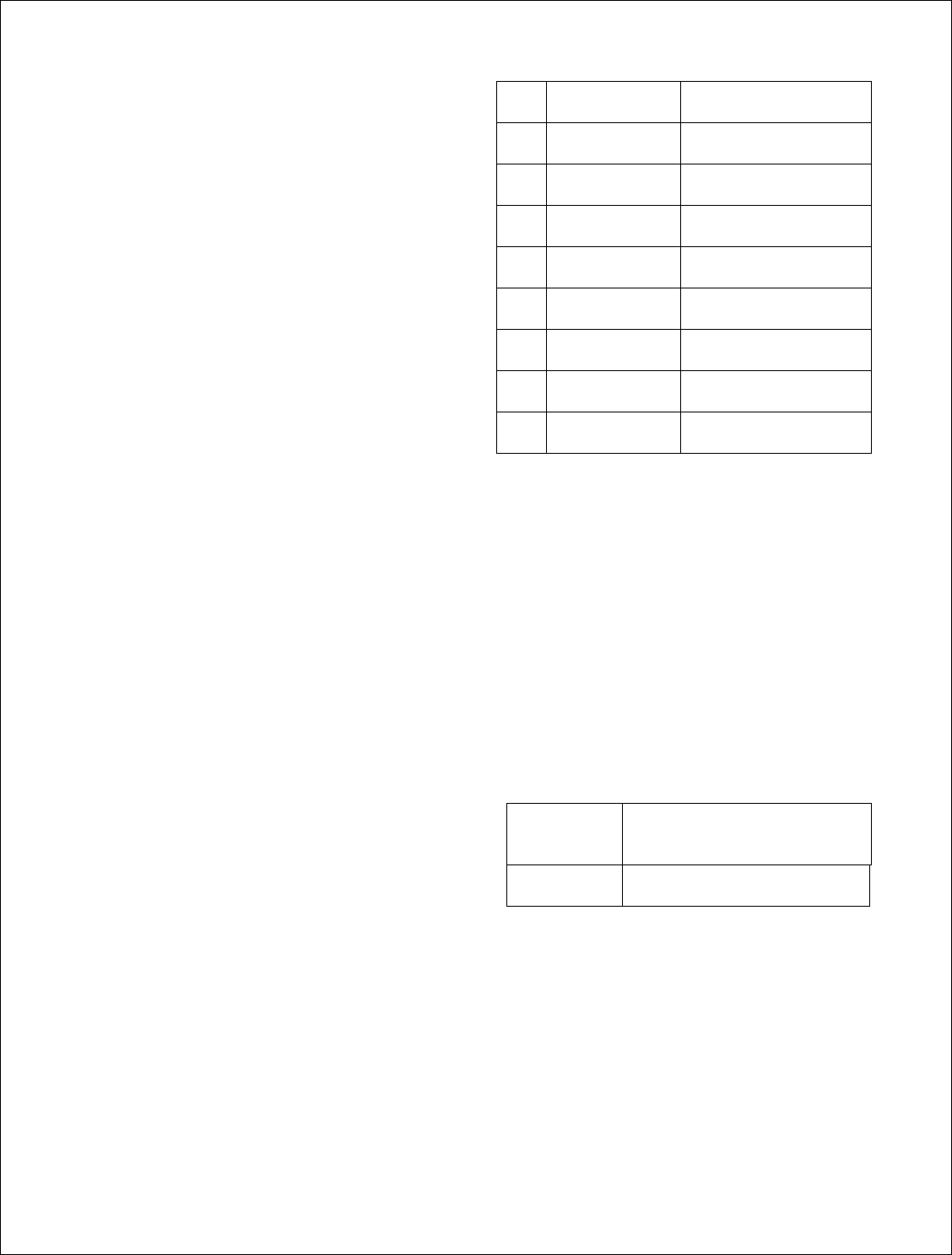
(3) RF W/AC
An AC surge protected SCTE compliant
female F-type connector for AC power
connection to the cable network. The input
line power must be between 50 VAC and 110
VAC with a line frequency from 50 Hz
through 60 Hz.
(4) ETHERNET
A 10/100BaseT IEEE 802.3/802.3u compliant
auto-sensing (MDI/MDIX) Ethernet port with
a weather-proof RJ-45 connector for all
outdoor connection to hardened media
converters and for connecting to customer
premise equipment.
To a data network the ODU is implemented
as a transparent bridge which passes
Ethernet frames of up to 1580 bytes. Port
based filtering is supported based on IEEE
802.1Q VLAN ID and port based prioritization
is supported based on IEEE 8021.p.
The Ethernet also supports operation as an
IEEE 802.3af Power over Ethernet (PoE)
source (PSE; delivers power) or powered
device (PD; accepts power) depending on the
configuration using 24 VDC power over
Ethernet (PoE) per the table below:
When the ODU is configured as a powered
device (PD) it can be powered by a PoE
source and when it is configure as a PoE
source it can be power PoE powered device
such as a hardened media converter. When
the ODU is configured as powered device
(PD) AC power is not required and should not
be used.
Pin Function US T-568A
1 Ethernet Tx+ green-white
2 Ethernet Tx- green
3 Ethernet Rx+ orange-white
4 PoE (+) blue
5 PoE (+) blue -white
6 Ethernet Rx- orange
7 PoE (-) brown-white
8 PoE (-) brown
(5) FUSE
An SCTE compliant replaceable 1 ampere
fuse providing over current protection for the
RF W/AC port.
(6) U/S Tap
Not Used.
(7) LED
Green/amber weather proof status LED
indicating:
Amber
Solid Status of unit is up
Green Solid Wireless link is established
(8) Ground Lug
The ground lug terminal is for grounding the
ODU per the appropriate electrical code in
the country of deployment.
Planning a MetroE Deployment
Wireless link planning is essential to the success of any microwave installation and is highly
recommended before attempting to install the equipment. In this section we will describe the
elements of the MetroE that are relevant to link planning. If the reader is unfamiliar with
microwave link planning he/she strongly advised to seek qualified assistance or take a suitable
microwave link planning training class.
Personnel installing the equipment must be familiar with fiber splicing, microwave and Ethernet
equipment solution installation and troubleshooting techniques.
Frequency Planning
The MetroE operates over the 5.725 to 5.850 GHz (defined as the ISM band) utilizing one20 MHz
wide channel. The band supports (5) non-overlapping channels and setting of the channel is done
manually. The MetroE link can be configured to use those channels that have been determined to
be free of interference from other users during the link planning process.
You are looking to find and use channels with signal strengths of -90 dBm or lower. If it is not
possible to find a completely clear channel, you can set the RSSI Threshold setting on the
Advanced Screen under Mesh Configuration, ADVANCED, screen) to just above the interfering
signal strength. The Hsyteresis Window, which determines the amount signal must come up past
above the RSSI Threshold, should be set to 3 dBm.
Distance
The MetroE FX5010-ODU can deliver full throughput at a range of 3 miles with 99.999% link
availability in a typical urban strand mount deployment. Link availability is calculated using the ITU
P-530 model which accounts for slow fading do to terrain and climate conditions and assuming a
near-line-of-site path with a multipath loss of 10 db. The Link Availability calculation does not
include potential downtime from transient interference or equipment failure.
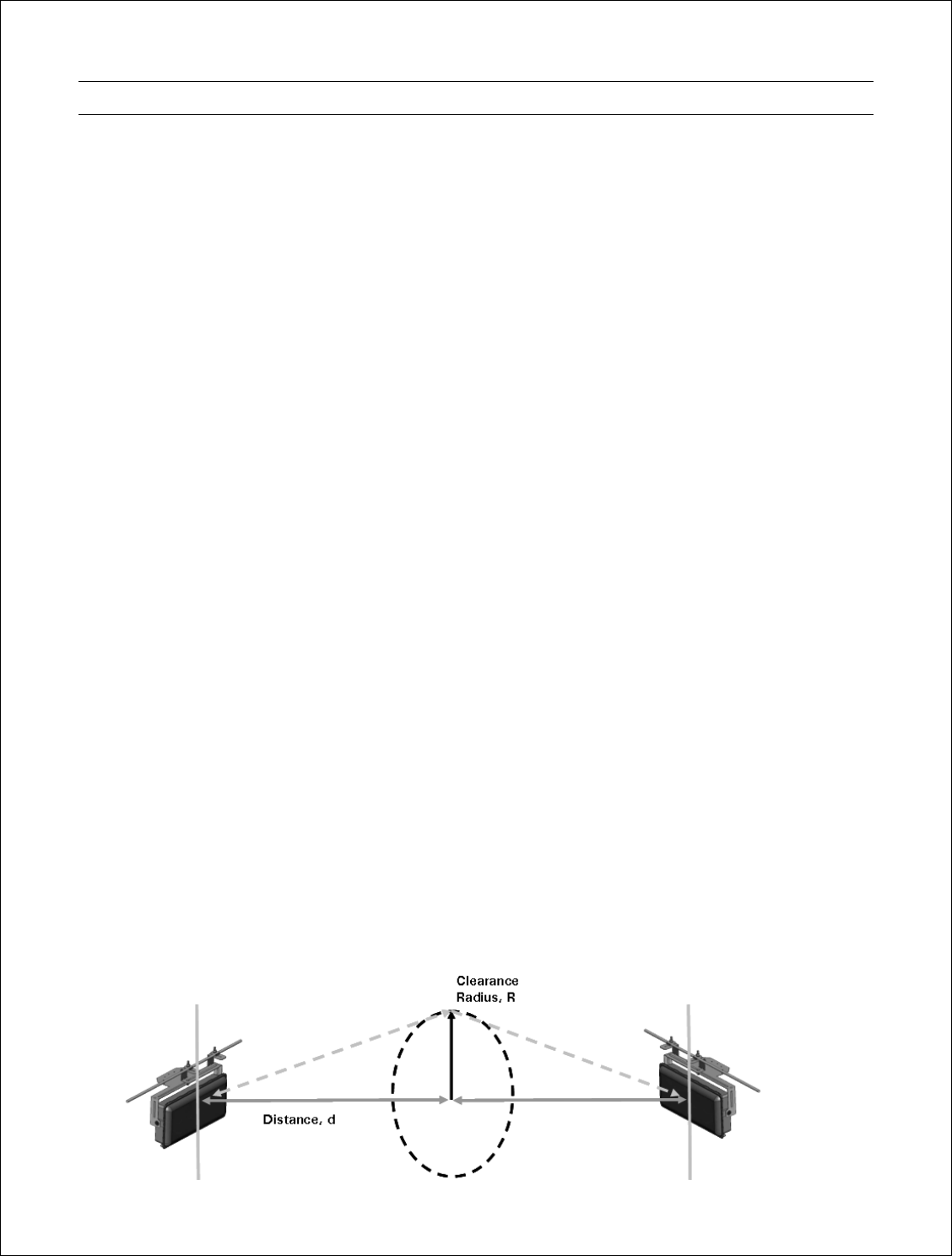
Path Profile
Optimal performance is ensured with a line of sight path between the two FX5010-ODUs. This is
defined as a path that is free of obstructions in the Fresnel zone. Obstructions can be trees,
buildings, street signs, etc. An accepted rule of thumb is that LOS conditions exist when there are
no physical obstructions within 60% of the 1st Fresnel zone (obstruction free zone). The Fresnel
Zone clearance is determined by the distance between the two ODUs as shown in the following
illustration and table.

13 of 47
Radius, R 20 feet* 16 feet 11 feet 10 feet 8 feet 6 feet
Distance, d 3 miles 2 miles 1 mile ¾ mile ½ mile ¼ mile
* Represent practical limit from strand mount 18 feet above the ground.
Link Planning Tools
Simple range calculation software is available from Arcwave for calculating operating distances for
specific applications and more complex link modeling software is available from third-parties for
very accurate link planning and using topographical maps of the area of interest. Contact Arcwave
Technical Support for additional information.
Locating the MetroE
The MetroE can typically be located anywhere along the HFC plant that provides a suitable
wireless path to the customer site. The hardened media converter is typically co-located with the
MetroE and connected to it using the 1 meter interconnect cable, FX5010-RJ45-1. With outdoor
rated CAT5e you can go up to 100 meters (327 feet) even when using the MetroE in power over
Ethernet power sourcing (PSE) or powered device (PD) mode. The hardened media converter can
typically be located anywhere from 10 to 40 km with 1310 nm and 100 km with CWDM (1430 to
1610) wavelengths from the head end.

14 of 47
ARCView Mesh Management Software for MetroE Nodes
The basic ARCXtend mesh network can be installed and operated without external network
management or intervention. However, because wireless network connections are invisible,
Arcwave provides the ARCView software to provide a graphical view of the mesh topology.
ARCView enables users to monitor the network connections and performance, and to customize
individual nodes or the entire network.
ARCView can be downloaded from the Arcwave website (www.arcwave.com/support.html) and
installed on a workstation connected with an operating system such as Windows, FreeBSD, or
Linux. The workstation must be connected to the mesh and requires Java runtime software, which
you can download.
The workstation can connect directly to any MetroE node on the mesh using a standard Ethernet
cable with an RJ-45 connector. After the user fills in the login information on the ARCView opening
screen, the software connects to the mesh and begins operation.
ARCView has a graphical interface for simple and intuitive operation. The following are some of
the basic features and functions of the software.
Mesh, Inventory, Performance, and Current Faults Views
You can view the mesh network in different ways. The Mesh view provides a graphical
representation of the mesh with additional information, including graphics that show the actual
interconnections between all of the nodes on the mesh. The Mesh view remains displayed when
you select one of the different view options described below. The Inventory view lists the MetroE
nodes on the mesh. It also shows the status, location, and other information for each node. The
Performance view shows the uptime statistics and traffic information for each node. The Current
Faults view shows the status of the nodes in the mesh, identifies the number of faults detected for
each node, and shows the available Ethernet ports on each node.
Mesh Setup
You can review and change all of the mesh-wide settings using ARCView, including network,
security, wireless (radio), and user account settings.
Node Management
ARCView also provides functions to manage individual MetroE nodes on the mesh. These allow
you to change the node’s name, location information, enable or disable Ethernet ports, and view
the node’s mesh connections. You can also view details about a selected node.
You can easily add new nodes to a mesh by exporting the configuration from an existing node on
the mesh and importing it into new nodes.
Easy Updates
Periodically Arcwave will post updates to the MetroE firmware that add improvements or new
features. With ARCView, you can update all of the MetroE nodes on your mesh in a single
operation.

15 of 47
Monitoring the Mesh
The Monitor feature of the software allows you to view network statistics to determine if there are
any problems with the communications between various nodes on the mesh.
For complete information on ARCView mesh management features and more detailed instructions
on its operation, install the software from the CD provided in the MetroE package or download the
latest ARCView User Guide, available at www.arcwaveinc.com/customer/support_extranet.html.

16 of 47
Installing ARCView
The ARCView Mesh Management Software is used to configure and manage a MetroE mesh
deployment. It should be installed on a workstation that will be connected to the MetroE mesh as
follows:
1. Install the software from the Arcwave website or from the CD-ROM included in the package.
2. Set the workstation’s IP address.
3. Connect the workstation to one MetroE node in the mesh.
Workstation Requirements
• Operating systems supported: Windows 2000/XP, Linux, Solaris, and FreeBSD.
• Java 2 Platform, Standard Edition, version 1.5 or later. This is available for downloading
from www.java.com/
• 1.0 GHz, 100% Pentium 4-compatible processor or later
• 256 MB of Random Access Memory (RAM)
• 50 MB of hard disk drive space
• 10/100 RJ45 Ethernet network interface
Install the Software
You can install the ARCView software from the CD-ROM disc included in the product package or
download the latest version from the Arcwave website. The instructions below describe how to
install the software onto a workstation.
1. Insert the installation CD into your CD drive
2. A Java installer applet will prompt you through the process. Follow the instructions to
download the software and save it on your workstation.
3. When prompted to select an installer, select the appropriate installer. If you are using
Windows, click on the Start Installer for Windows… button. If you are using a different
operating system, download the appropriate installer and follow the instructions provided
at the bottom of this screen. When a dialog box appears to ask where you want to save the
software, specify the desired location on your workstation and click on the Save button.
4. When the Installation of ARCView screen is displayed, click on the Next button.
The license agreement is displayed.

17 of 47
5. Select the ‘‘I accept the terms of this license agreement button’’ and then click on the Next
button to continue. A screen showing the default location for the ARCView software is
displayed.
6. To enter a different installation location, type in the path to the desired location or click on
the Browse button to select a location.
7. Click on the Next button to install the ARCView software in the location displayed on screen.
A screen showing the progress of the installation is displayed.
8. When the installation is finished, click on the Next button. A screen showing the available
shortcut options is displayed.
9. Select the desired shortcut options and then click on the Next button. An installation has
completed message is displayed.
10. Click on the Done button. This completes the ARCView software installation.
Set the IP Address for the ARCView Workstation
For Windows XP
1. Click on the Start button.
2. Click on Control Panel.
3. Double-click on the Network Connections icon.
4. Double-click on the Local Area Connection icon for the network adapter that will be used to
connect to the mesh network.
5. Click on the Properties button under the General tab.
6. Click once on Internet Protocol (TCP/IP) to highlight it, and then click on the Properties
button.
7. Select “Use the following IP address” and enter the following information:
IP address: 192.168.224.10
Subnet mask: 255.255.255.0
8. Click OK to finish.
9. Close the other dialog boxes.
For Other Operating Systems
1. Refer to the documentation provided with your operating system for instructions on setting
up IP addresses and subnet masks.
2. Set up your workstation with the following network parameters:
IP address: 192.168.224.10
Subnet mask: 255.255.255.0
18 of 47
Using ARCView
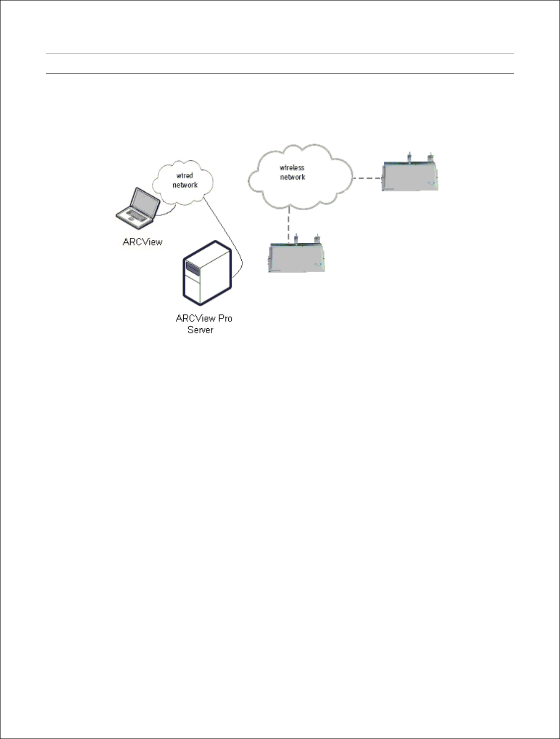
The initial mesh setup should occur prior to installation. To complete initial setup connect one
MetroE node to a wired connection with access to ARCView and place the other node within
wireless range as show in the figure below.
Verify that the status LED on each MetroE node glows Amber indicating it’s powered and then
green indicating it has achieved a valid link status.
Launch ARCView Management Software
You are now ready to check your mesh configuration using the ARCView mesh management
software. The steps below describe how to launch the ARCView software under Windows. Your
operating system may have a different procedure for launching applications. If necessary, refer to
your operating system’s documentation for instructions on how to launch applications.
1. Install the ARCView mesh management software as described in the ARCView User Guide.
2. Configure your TCP/IP settings to:
IP address: 192.168.224.10
Subnet mask: 255.255.255.0
Gateway is not used
3. From the Windows Desktop, click on the Start button.
4. Click on All Programs and select ARCView. The Login screen will appear.
5. Enter the following information to log into the mesh network:
Mesh IP address: 192.168.224.150
Username: admin
19 of 47
Password: arcwave
6. Click on Login.
7. Wait for your computer to connect to the mesh. This may take a few seconds to several
minutes, depending on how many nodes are in the mesh. You should see a screen with a
list of all of the MetroE ODI units on the mesh.
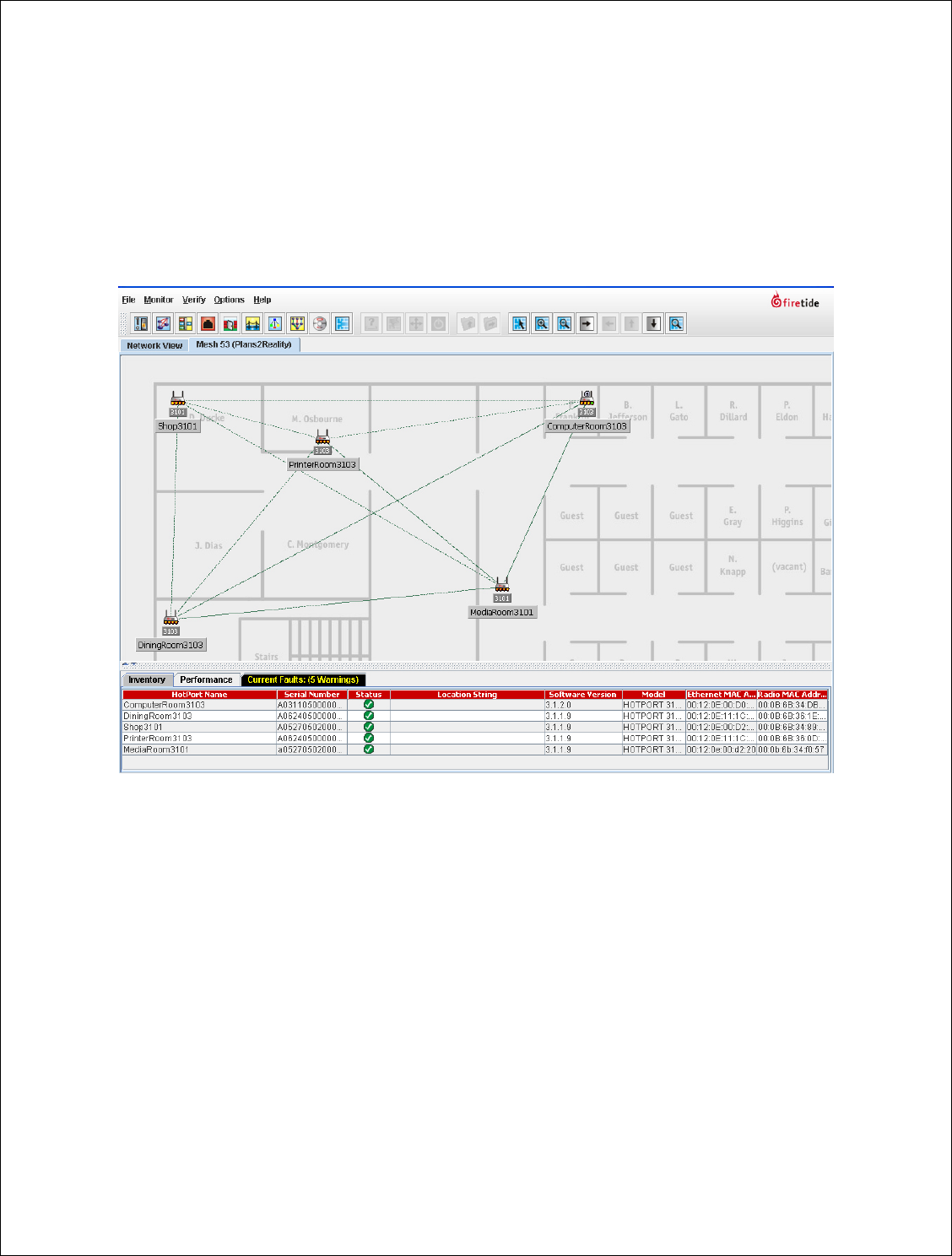
8. Ensure the MetroE nodes are visible in the Network View or the Inventory screen. The node
connected to the ARCView is indicated with a small ‘‘H’’.

20 of 47
Quick Mesh Check
The first step after logging into a mesh for the first time is to ensure all of your MetroE nodes are
visible to ARCView. This can be verified on the Mesh diagram, or in the Inventory screen. In
particular, check the columns of information described below to ensure that all nodes are included.
(If the Inventory screen is not displayed, click on the Inventory tab at the bottom of the screen.)
There are a number of reasons why the MetroE node may not be visible:
The MetroE node is not powered.
Ensure that the node is powered; the status LED should turn amber in 70-80 seconds
indicating the unit is up and then green indicating a wireless link has been established with
another unit.
The MetroE node is out of radio range.
To test this, temporarily move the MetroE node closer to one of the MetroE nodes that appear
on the ARCView screen. If the node appears on the screen after doing this (usually within 30
seconds), it was probably located too far from the rest of the mesh. You can either relocate it
closer to the rest of the mesh or add one or more additional MetroE nodes between the mesh
and the desired location. You can use a third-party software tool to help troubleshoot node-
connection problems.
The MetroE node is set to a different RF channel or mode.
All nodes must have identical radio settings.
The MetroE node has encryption enabled.
All nodes must be running the same encryption type and key.
The MetroE node has a different password.
All nodes must have the same password; the admin and guest node accounts are what
ARCView Pro uses to log into and control each node.
The MetroE node has been factory-reset.
If the nodes have been reset, it will not join an existing configured mesh. The easiest way to fix
this is to save the configuration from an existing node, then connect to the factory-reset node
via Ethernet and upload the configuration file.
21 of 47
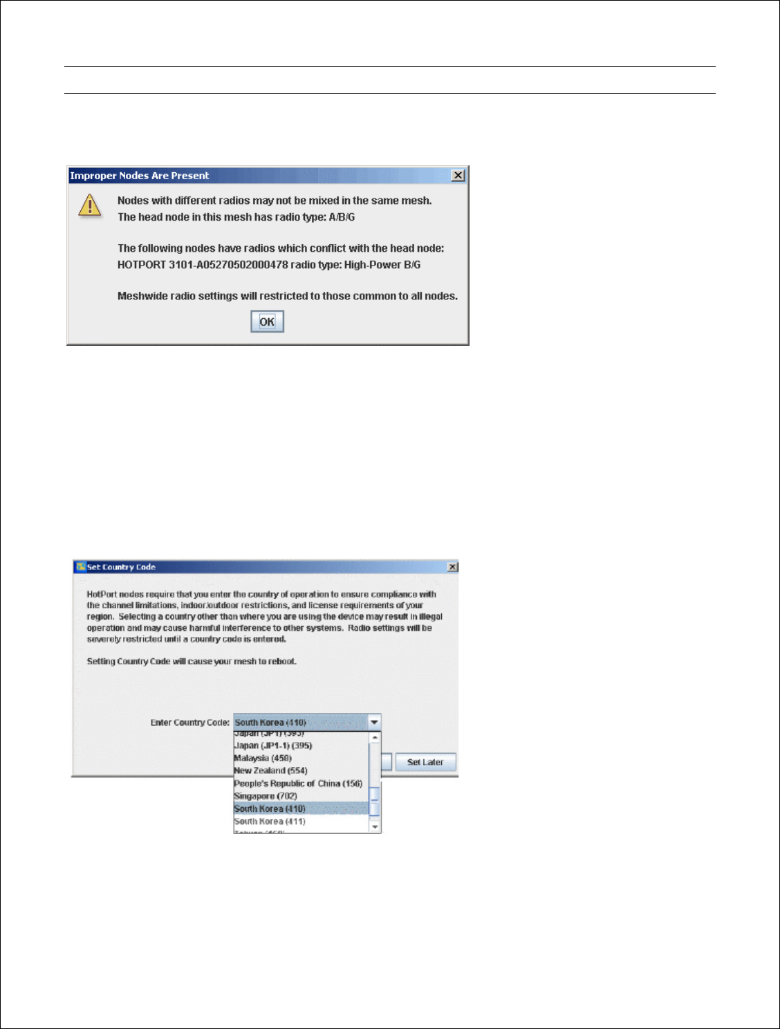
Country Code Setting
If your mesh has radios which require a country code setting, and the country code has not yet
been set, the Set Country Code message will appear.
The Country Code settings allow operation at the maximum legal limit for that country; if it is not
set, the transmitters operate at very low power and range is limited. Until the Country code is set,
the default radio mode is 5.8 GHz DSSS, and the default radio channel is 161.
1. Make sure all radios are visible on the mesh.
2. Select the proper Country Code from the drop down list. Note that some countries have
several codes from which to choose.
3. Click the Set Country Code Now button to set the Country Code for all of the mesh radios. If
you click Set Later, the ‘‘Set Country Code’’ message will reappear later and the mesh will
continue to operate with severe limitations until a Country Code is set.
22 of 47
Customizing Your Mesh Network
There are several mesh parameters which must be specified for correct mesh operation. All
MetroE nodes on any given mesh must share the following properties:
• IP Address
• ESSID
• Radio channel
• Encryption type and key
• Login and password
Moreover, any node which has the same settings as other nodes will join that mesh. Thus, if you
leave the default settings unchanged, any MetroE node can automatically join your mesh. This can
cause problems. Arcwave recommends that you change the ESSID and password at a minimum
and we recommend you enable encryption as well.
Mesh Configuration
The mesh network parameters are configured using the Configure Mesh dialogue box. To access
the Configure Mesh dialogue box, click on the File menu and select Configure Mesh.
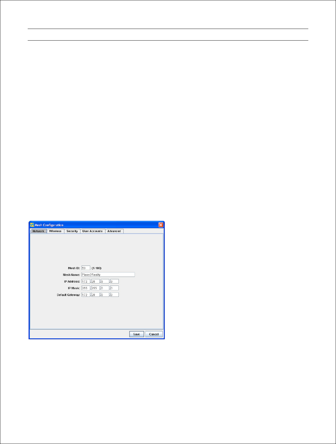
Network Settings
To set the Mesh ID number, Mesh Name and IP address of the Mesh to be used for network
management click on the Network Tab. The default address assigned by Arcwave is
192.168.224.150.
After entering the new values, click on Save to apply. A confirmation dialogue box will appear.
If want to save your new settings and reboot the mesh, click on Yes. Changing the login settings
will cause the ARCView software to restart. This may interrupt all mesh operation for
approximately one minute until the new settings are loaded into all of the MetroE nodes and all
23 of 47
units are restarted. Otherwise click on No and then on Cancel to return to the previous settings.
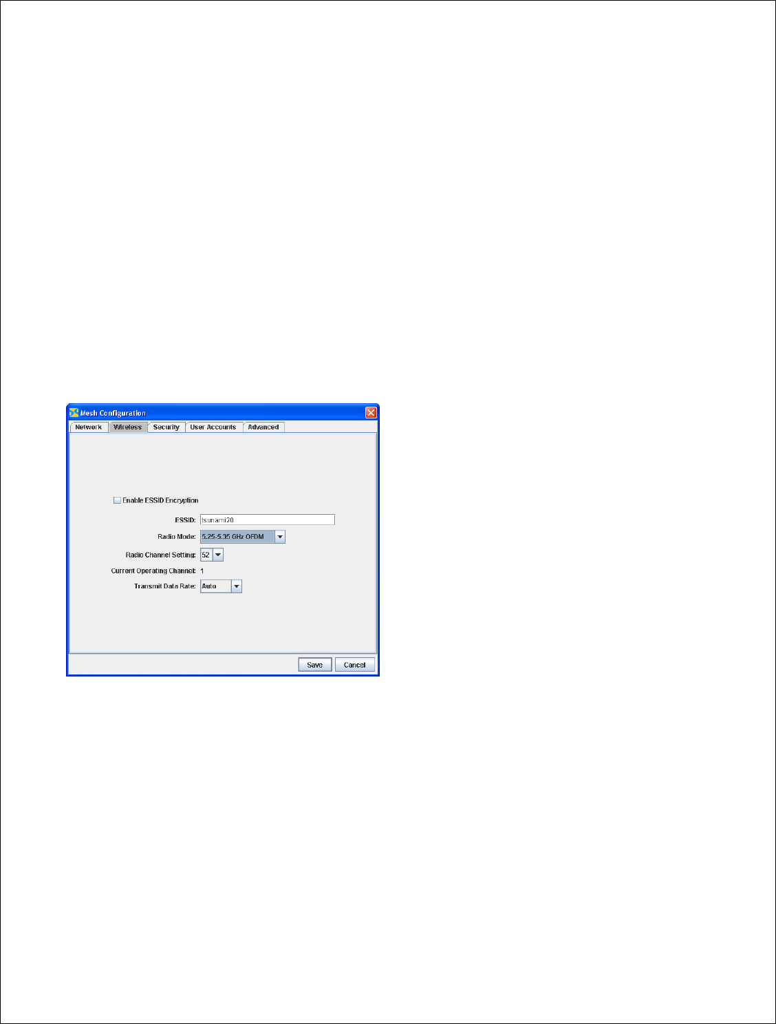
Wireless Settings
To set the Extended Service Set Identifier (ESSID), Radio mode, and Radio Channel setting click on
the Wireless Tab.
• The default ESSID is METROE_MESH. You should change it to a more descriptive name.
• The Radio Mode is set to 5.725 to 5.850 GHz OFDM. This is the only radio mode FCC
approved for operation in the U.S..
• Radio Channel Setting should be set to the best available channel which is generally
defined as the channel with the least amount of interference as determined during the site
survey.
• Current Operating Channel displays the channel number.
• Transmit Data Rate should be set to the lowest data rate that meets the service level
agreement (SLA) requriements. In most deployments this will be 54 mbps. Note that the
data rates are raw data rates and actual data rates.
After entering the new values, click on Save to apply.
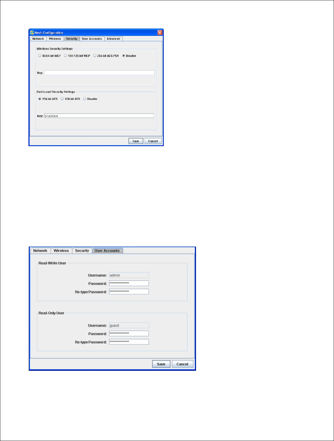
Security Settings
Set radio security to WEP, AES or no encryption. Note that the use of WEP or AES does not slow
throughput. Encryption is disabled by default.
• If you select 104/128-bit WEP, enter a 26 hexadecimal character key.
• If you select 40/64-bit WPE, enter a 10 hexadecimal character key.
• If you select 256-bit WAP, enter a 64 hexadecimal character key.
• If you select 128-bit WAP, enter a 32hexadecimal character key.
24 of 47
After entering the new values, click on Save to finish.
User Accounts
Set the Usernames and Passwords for Read-Write User and Read-Only User Access.
You can set up two types of access for ARCView users: administrator (‘‘admin’’ or ‘‘Read Write
User’’) or guest (or ‘‘Read Only User’’) access. Admins can view and modify (read and write) the
mesh configuration, guests can only view the information (read-only). To set up an admin, enter
the user’s account information in the Read-Write User fields. To set up a guest, enter the user’s
account information in the Read-Only User fields. The password can be up to 15 characters.
After entering the new values, click on Save to finish.

25 of 47
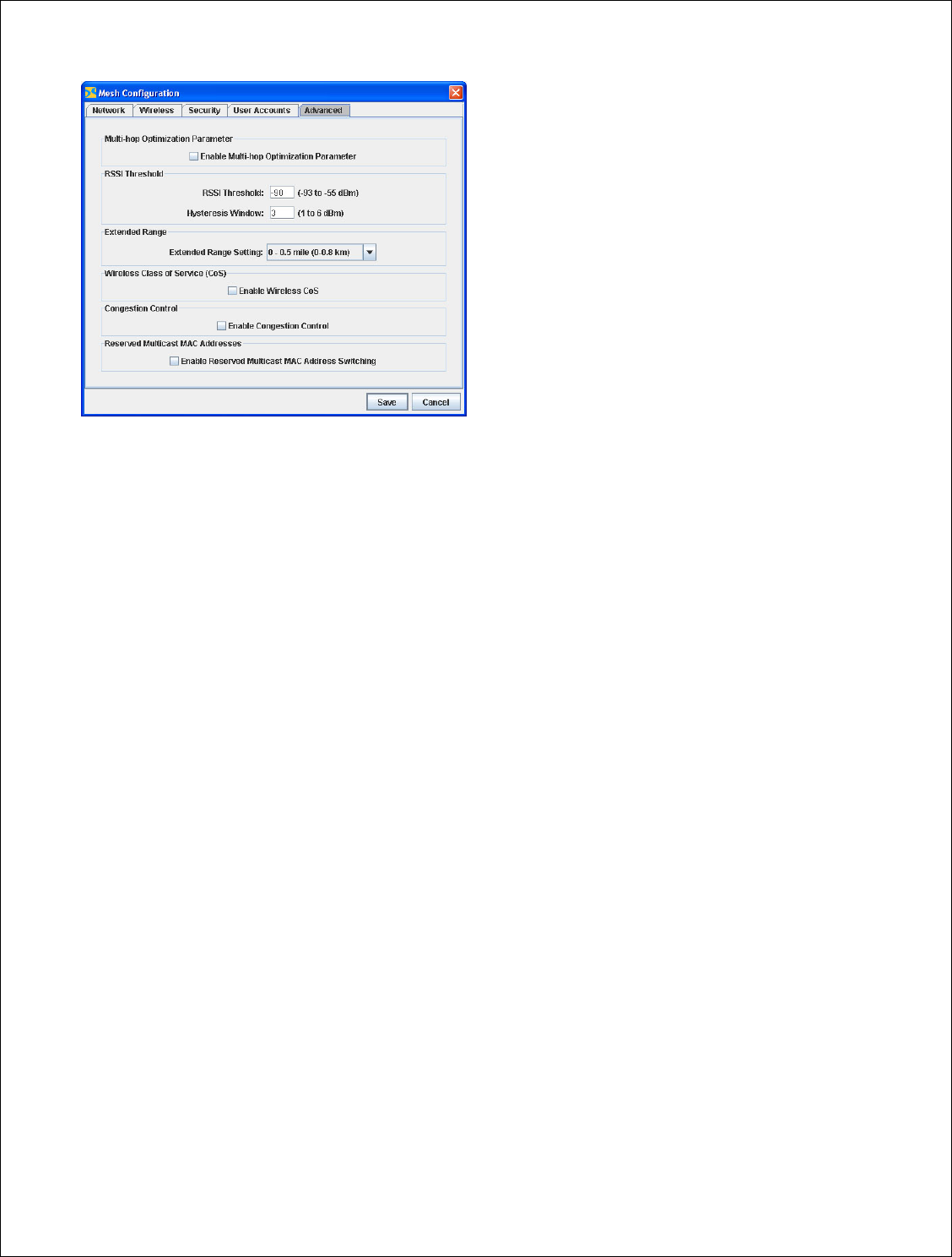
Advanced Settings
Multi-hop optimization
The multi-hop optimization option increases the overall throughput of the mesh by reducing the
amount of contention between radios that are separated by multiple hops. Normally this option
should be enabled since most mesh networks will have multiple hops between radios. However,
you should disable this mode if you have a fully meshed scenario where all modes connect
directly to every radio with a single hop.
For point to point or point to multipoint network configurations this mode should be disabled.
RSSI Threshold
The RSSI Threshold allows you to set the quality threshold for wireless links. Any links that drop
below the threshold will not be used for routing traffic. For the routing ability of the link to be
restored, the RSSI must achieve the Threshold setting PLUS the Hsyteresis Window setting. For
example if the RSSI Threshold is -80 dBm and the Hsyteresis Window is 3 dBm, routing over the
link will not be restored until its RSSI is -77 (-80 dBm plus 3 dBm).
When a clear wireless channel cannot be found, the RSSI Threshold can be used to distinguish
between relatively weak interfering signal and the desired signal by setting the RSSI Threshold
value just above the interfering signal strength.
Extended Range
Just like conventional Ethernet, the Arcwave mesh network adheres to careful timing rules
regarding when a radio can, and cannot, talk. These rules minimize collisions and maximize
throughput. The default timing parameters set by Arcwave provide optimum performance for
most applications where radios are fairly close. However, networks which use high-gain directional
antennas will benefit from having the timing parameters optimized for the longer propagation
time.
If your mesh has one or more links which exceed approximately ½ mile, use the appropriate
extended range setting.
Wireless Class of Service
Should be set to ‘‘Disable’’.
Congestion Control
Should be set to ‘‘Disable’’.
Reserved Multicast MAC Addresses
Should be set to ‘‘Disable’’.
26 of 47
After entering the new values, click on Save to finish.
27 of 47
Configuring Individual Nodes
Individual nodes can be configured as follows:
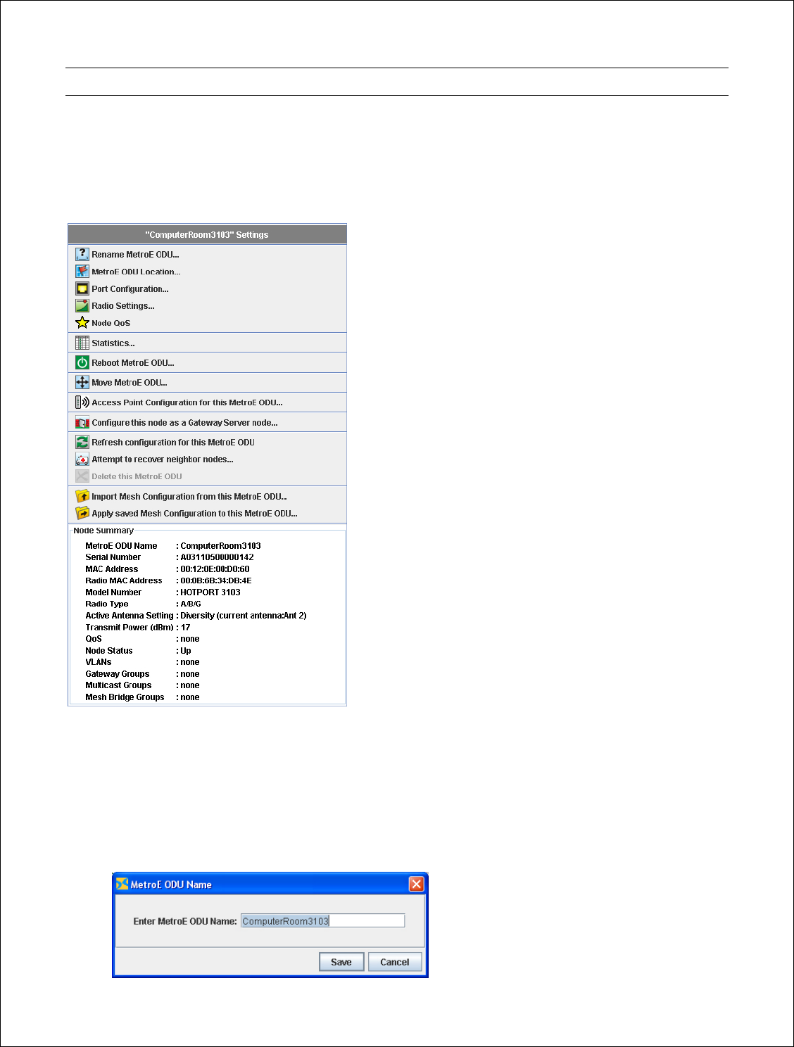
4. On the mesh diagram, right-click on the icon of the MetroE node you want to reconfigure. A
pop-up menu appears.
5. Select the option you want or click on a blank portion of the mesh to hide the menu.
Rename the MetroE Node
You can change the factory default node name to something more meaningful:
1. In the mesh view, right-click on the MetroE node icon whose name you want to change. A
pop-up menu appears.
2. Select Rename MetroE. A dialog box appears.
28 of 47
3. Enter a new name (up to 32 characters long) and click on the Save button.
4. Repeat the above steps for all of the ARCXtend MetroE radios that you want to rename.
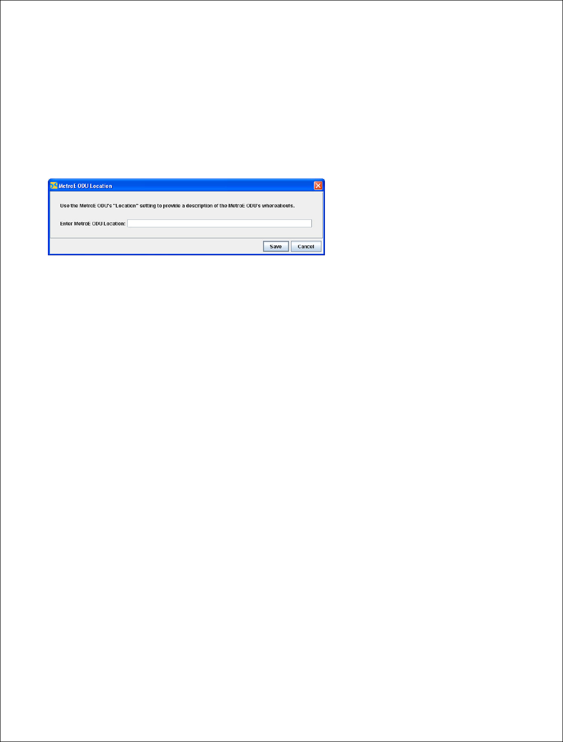
MetroE Location
Use this option to enter any unique identifying information about the MetroE node, such as its
location, a contact person’s phone number, and so on. Enter the Metro
Port Configuration
You can configure the Ethernet port on each MetroE node. The screen used to configure ports is
divided into sections. Each port on a radio has its own section.
Enabling and Disabling Ports
The MetroE FX5010 has only one accessible port and it is Port 4. Ports 1, 2 and 3 should be set to
‘‘Disable’’ and Port 4 should be to ‘‘Enable’’.
Class of Service
Since the MetroE FC5010 as only one port, this feature is not used.
You can assign priority settings to specific Ethernet ports to configure the priority levels of these
ports/services. Each port can be assigned a priority of Low, Medium, or High. The default priority
of each port is Low. The priority property is propagated throughout the mesh. In other words, if a
packet exiting from a port is assigned High priority; all other radios on the mesh treat the packet
with a High priority.
This feature is useful for assigning priorities to ports associated with certain applications. For
example, if a certain port is used for Voice over IP or other traffic requiring a low latency, you
might want to assign the port a High priority.
Select the desired priority for a port by clicking on the Priority drop-down menu.
Speed/Duplex
You can configure each Ethernet port for 10 or 100 Mbps speed or for automatic speed
negotiation. Each port can also be configured for full- or half-duplex operation.
To configure a port for auto-negotiation of speed and duplex settings, select Auto-Negotiate
Speed/Duplex.
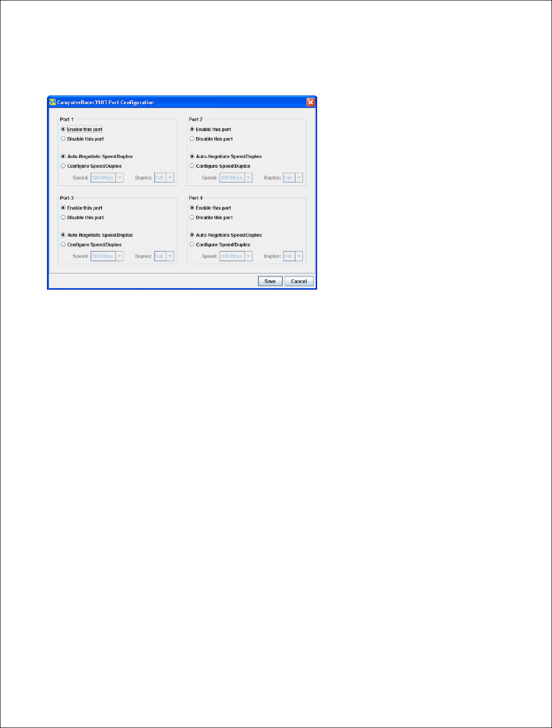
29 of 47
To configure a port for a specific speed or duplex setting, select Configure Speed/Duplex. To select
a specific speed, click on the Speed drop-down menu. To select a specific duplex option (Half or
Full), click on the Duplex drop-down menu.
Click on the Save button after all port settings have been properly configured.
Configuring Packet Filters (MAC Filters)
MetroE nodes can filter packets based upon the MAC (Media Access Control) address (also called
‘‘physical address’’) of the device sending the packets. A MAC address is a 48-bit number
represented by 12 hexadecimal digits that uniquely identifies the manufacturer and the device. On
Arcwave ARCXtend MetroE radios, each wired Ethernet port and the radio port has a MAC
address.
You can configure specific Ethernet ports to either deny or permit access to the mesh for traffic
coming from specific devices (identified by the devices’ MAC addresses). You cannot both deny
and allow access to specific MAC addresses. The number of MAC addresses you can filter is
limited only by the radio’s available memory. By default, packet filtering is turned off.
WARNING: Use of the ‘Allow’ MAC address filter can cut off management access to the MetroE
mesh. The ‘Allow’ function only permits explicitly identified MAC addresses to pass the radio. If
the MAC address of the ARCView Pro Server host machine is not included, access is denied. Many
enterprise networks use Ethernet switches; if the MAC address of the switch port connected to the
radio is not included, access is denied. If the wired connection is moved from one port to another,
access will be denied.
30 of 47
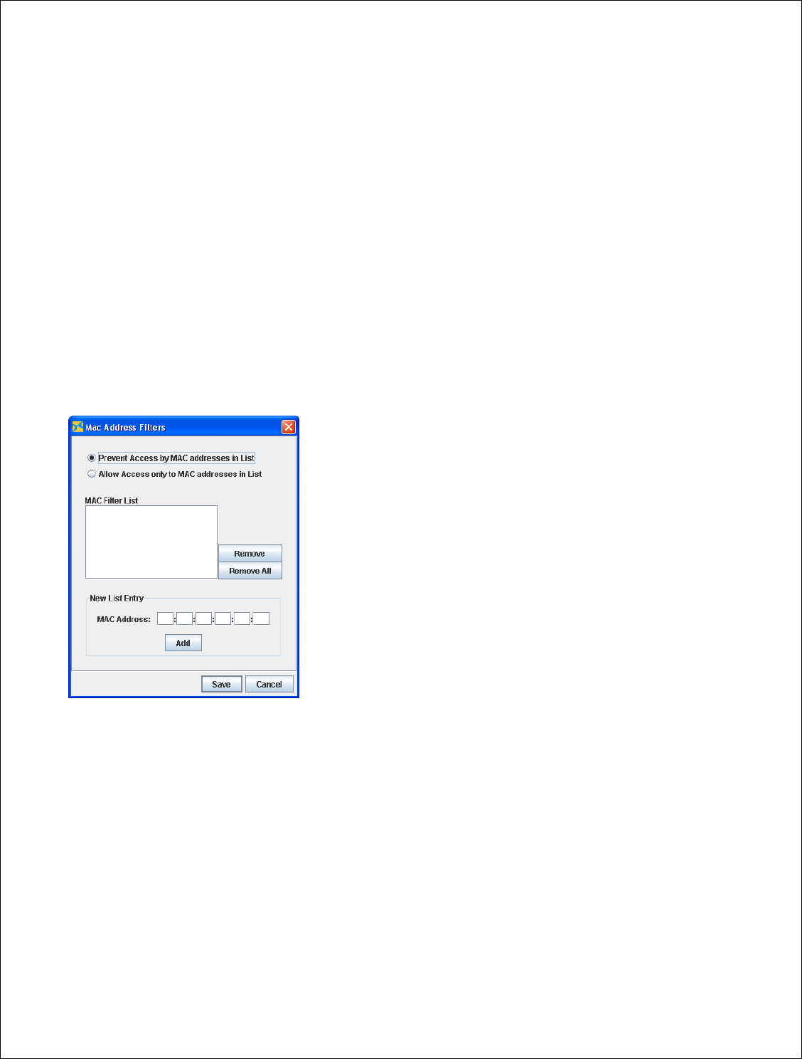
1. Click on the File menu and select MAC Filters. A dialog box appears.
2. To prevent access from specified devices (‘‘deny’’), select Prevent Access by MAC addresses
in List; to allow access from only specified devices (‘‘permit’’), select Allow Access only to
MAC addresses in List.
3. Type in the MAC address for the device you want to either prevent or allow access to the
wireless mesh in the MAC address fields. Click on the Add button. The specified MAC
address appears in the MAC Filter List box.
4. Repeat the above step to enter additional MAC addresses.
5. To delete a one or more MAC addresses from the list, select the MAC addresses you want to
delete and click on the Remove button; to remove all MAC addresses from the list, click on
the Remove All button.
6. Click on the Save button when you’ve finished defining MAC addresses.
Note: To switch from denying access to specified MAC addresses to allowing access to specific
MAC addresses (or vice versa), delete all the existing MAC addresses, and save your changes.
Then select the MAC Filters command again, select the other operation (for example, if you
previously allowed access, select the prevent access option), add the new MAC addresses, and
then save your changes.
31 of 47
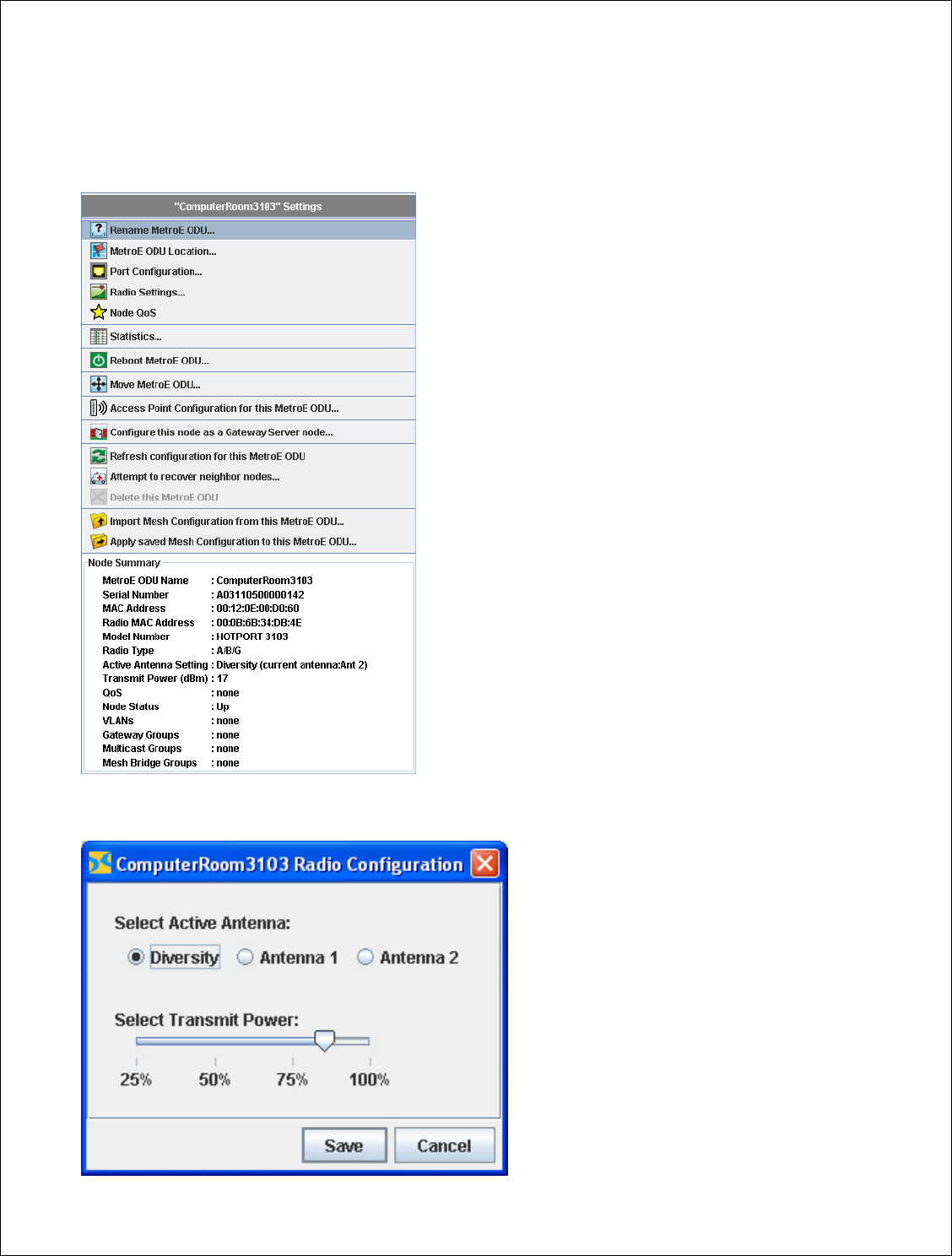
Select Transmit Power Level
To change the transmit power level of a given node, right click on that node. This will bring up the
following Node Summary dialogue box.
Left click Radio Settings…

32 of 47
You can change the transmit power of the radio to 25%, 50%, 75%, or 100% of the approved
maximum output power. Use the table below to determine the % attenuation conversion. Drag the
slider to select the desired power level and then click on the Save button.
TX Power Level TX Attenuation MetroE Node EIRP
100% 0 dB = 20 dBm TX Power + 17 dB Antenna Gain = 37 dBm
90% 2 36
85% 3 35
75% 5 33
70% 6 32
60% 8 30
55% 9 29
50% 10 28
40% 12 26
30% 14 24
25% 16 22
The transmit power should be set to 90% under normal circumstances.
Setting Active Antenna
The active antenna must be set to 1.
33 of 47
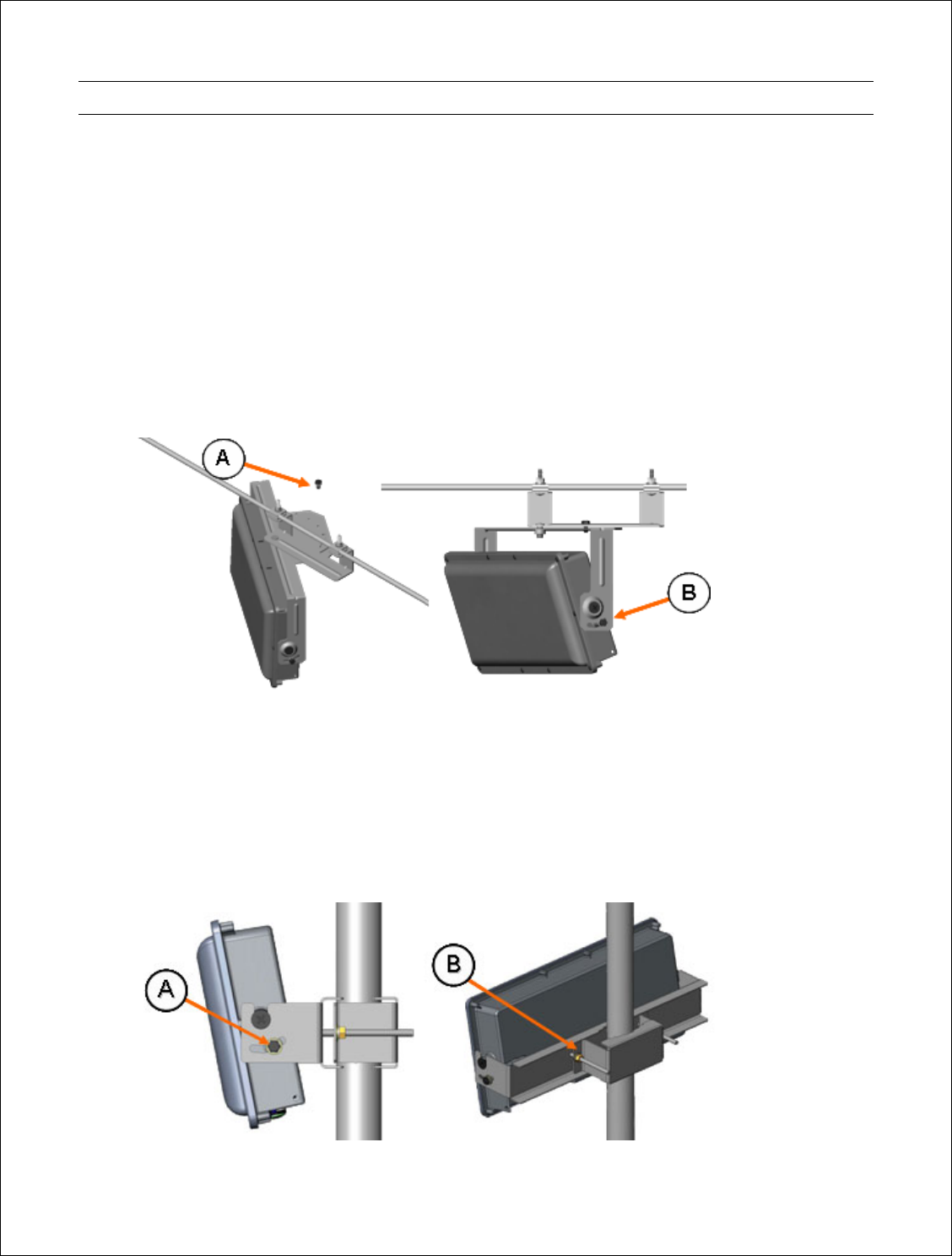
Installing Nodes
Strand Mount Bracket Installation
The strand mounted MetroE is designed for installation directly onto standard strand wire and
comes with the bracket pre-installed onto the unit. A 7/16’’ wrench is the only tool required for
mounting and aligning the hub.
Attach the bracket to the messenger strand with the two hanger bolts. Position the MetroE’s
antenna (located behind the radome) to the azimuth and elevation determined in the wireless link
planning process. The azimuth position is adjusted by placing bolt A in the appropriate location on
the azimuth alignment bracket and the elevation is adjusted by loosening bolts B and rotating the
MetroE face up or down and tightening bolts B at both ends.
Mast Mount Bracket Installation
The mast mounted MetroE is designed for installation directly onto a mounting pipe with of 1-1/2’’
4’’ in diameter and comes with the bracket pre-installed onto the ODU. A 7/16’’ wrench is the only
tool required for mounting and aligning the hub. The MetroE and mounting pipe require a
minimum of 12 inches clearance on all sides for optimal performance.

34 of 47
To install and align the MetroE:
• Loosen the two mounting bolts, B, and slide the bracket over the mounting pipe. Position
the MetroE antenna (located behind the radome) to the azimuth position determined in the
wireless link planning process and snug the mounting bolts, B.
• Loosen the two alignment bolts, A, position the MetroE antenna to the elevation
determined in the wireless link planning process and snug the alignment bolts, A.
Grounding the MetroE
The MetroE must be properly grounded per section 810 of the National Electrical Code, ANSI/NFPA
No. 70-1984, Section 54 of the Canadian Electrical Code or the applicable electrical code in the
country of deployment. The MetroE includes a ground lug for this purpose.
Powering the MetroE
Powering the MetroE with AC Line Power
To power the MetroE using the AC line powering from the coaxial cable plant:
• Install a CATV power extracting tap suitable for your plant and the ODU powering
requirements. The hub draws 32 watts maximum and can accept 50 Vac and 110 Vac.
• Connect the tap to the RF W/AC F-type connector on the ODU.
• The LED on the ODU should glow solid amber if the ODU is powered.
Powering the MetroE ODU with DC Power over Ethernet
To MetroE can be powered using a 20 to 48 VDC (+ or -) IEEE 802.3af compliant power over
Ethernet source (PSE). The PSE could be the hardened media converter on the network side or a
Power-Over-Ethernet Injector and Power Supply on the customer site side.
• Make sure the MetroE is configured as power over Ethernet (PD; powered device) unit. The
model number on the MetroE will indicate ---PD.
• Make sure that the voltage drop across the planned length of CAT5 cable is acceptable. The
typical resistance of a CA5 cable is approximately 3 ohms per 250 feet. The MetroE E
requires +24 to --- 48 VDC and draws a maximum of 20 Watts.
• Install a CAT5 Surge Suppressor, FX5010-SS-CAT, between the PSE and the MetroE to
protect the PSE and the customer premise equipment from power surges due to lightning.
• Connect the CAT5 cable connected to the PSE to the weatherproof RJ-45 port on the
MetroE.
• The LED on the MetroE should glow solid amber if the ODU is powered.
Connecting Ethernet Devices
One Ethernet device can connect to the MetroE via the weather proof RJ-45
port. The MetroE accepts a Molex P/N 84700-0002 Industrial Ethernet Plug.
35 of 47
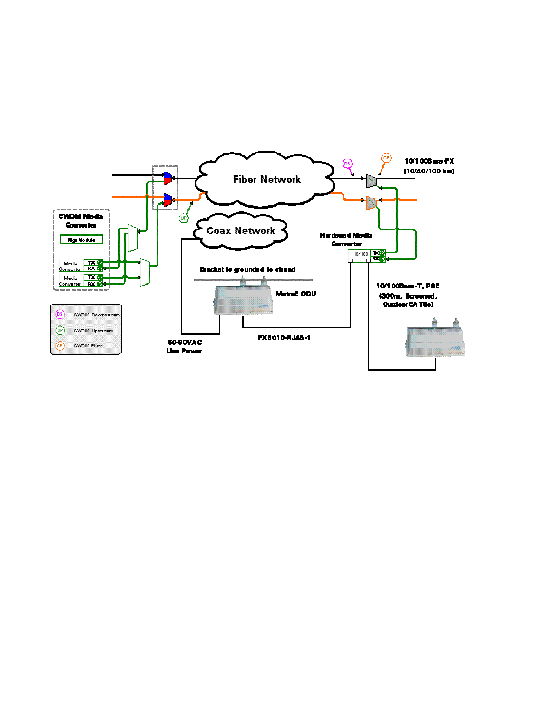
Strand Mount Deployment Diagram and Material List
The diagram bellows depicts a typical network side strand mount deployment using CWDM
(Coarse Wave Division Multiplexing) Fast Ethernet media converter to connect to the fiber network.
The media converter provides power to the MetroE node.
The required components are:
• Strand Mount, PoE Powered Device ARCXtend MetroE WPE ODU--- Arcwave Model FX5010-
ODU-SM-PD
• CWDM Fast Ethernet Media Converter
PCT Model THC or THP2312BTFC-Czz, where zz is the CWDM channel. The THC and
THP-2312BTFx are designed to operate in conjunction with the CCT-2312-BTFx Series
chassis line card.
Aurora PG1210A-00. The CWDM SFP plug-in modules are ordered separately.
• MetroE ODU to media converter interconnect cable, Arcwave FX5010-RJ45-1 one meter UV
protected outdoor CAT5e cable with weather proof RJ-45 connectors
• CWDM Optical Couplers/Filters for connecting the media converter to the fiber plant,
Aurora OP941S-xxxx-R3-00 where xxx is the CWDM wavelength
• Fiber Splice Enclosure, if one does not exist. Available from various suppliers
36 of 47
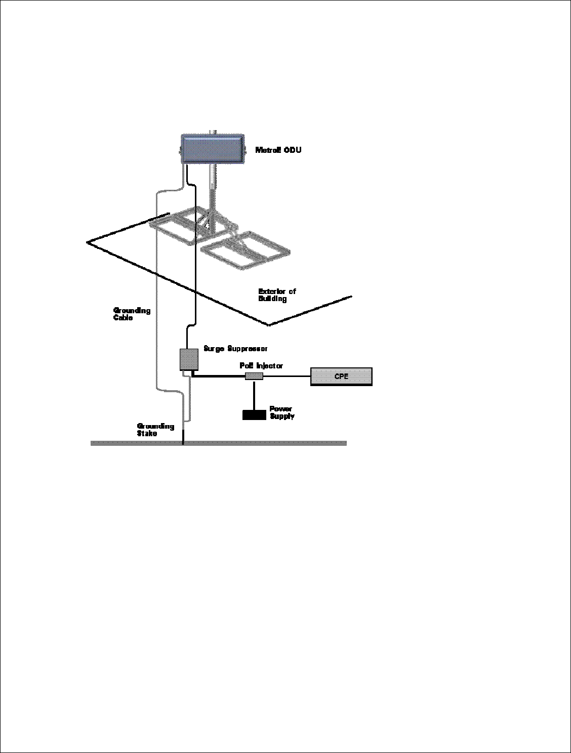
Rooftop Deployment Diagram and Material List
The diagram bellows depicts a typical customer side mast mount deployment using a non-
penetrating roof mount kit.
The required components are:
• Mast Mount, PoE Powered Device ARCXtend MetroE WPE ODU --- Arcwave Model FX5010-
ODU-VM-PD
• Non-penetration Roof Mount. Arris / Telewire PTX-NPR - xxxy
• FX5010-PS-48V 48 VDC Power-Over-Ethernet Injector and Power Supply
• FX5010-SS-CAT5 CAT5 POE Compatible Surge Suppressor
• 8 AWG Grounding Cable (minimum gauge)
• Grounding Stake

37 of 47
Aligning Nodes
The next step in the installation process is to align the customer-side MetroE node to the plant-side
node for maximum signal strength using the RSSI (received signal strength indicator) metric on
the ARCView Statistics screen:
1. Connect the mesh to a network containing ARCView.
2. Launch ARCView and login to the mesh network.
3. Right click the network on the Network View. This will launch the Node View screen
showing all the MetroE nodes in the network.
4. Select the customer-side MetroE Icon on the Node View screen. A drop down menu will
appear.
5. Left click on Statistics. This will bring up among other parameters, the RSSI value of the
node.
6. Adjust the horizontal, vertical and up/down tilt of the MetroE ODU until the maximum RSSI
value is achieved. Note each change will take approximately 5 minutes to register on the
screen. (Note that these are negative number, so -85 dBm is a stronger signal than -95
dBm.)
(a) The
RSSI value should be greater than ---60 dBm in order for the radios to reliably
associate and pass data.
(b) The
RSSI value must be greater than the RSSI Threshold set for the Mesh Network.
The RSSI value is typically set above interfering signals found during the site survey
process.
7. Check that the RSSI value of the network side MetroE node is greater than -60 dBm or the
RSSI Threshold plus the Hsyteresis Window.
(c) If you cannot achieve the desired result, you may need to adjust the network side node
and/or check the path between the two nodes.
38 of 47
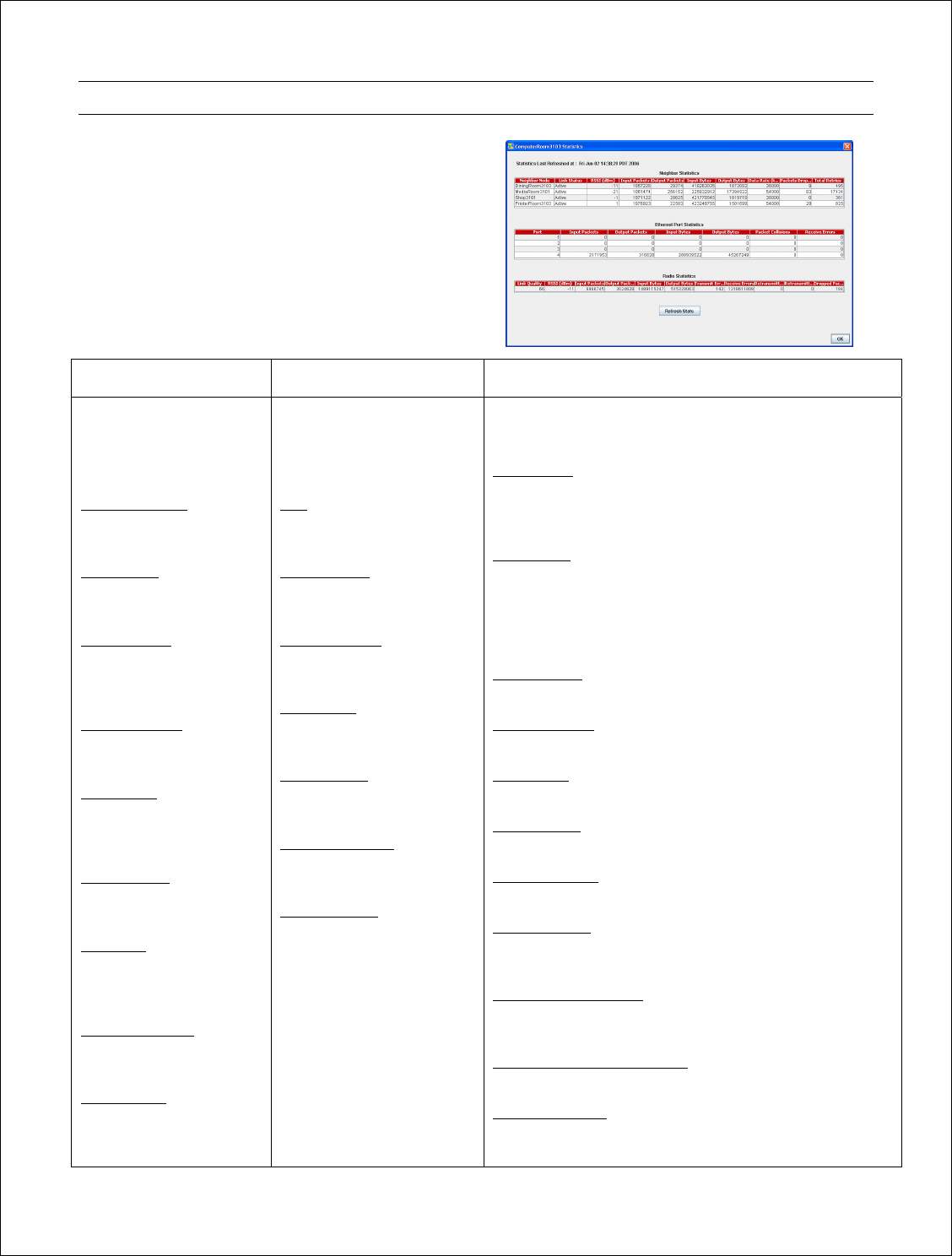
Link Verification
The final step in the installation process is to
verify the performance of the new link using the
Statistic screen and an Ethernet traffic generator.
To access the Statistic screen, right click on the
new node icon. This will bring up the Node
Summary dialogue box shown earlier. Left click on
Statistics. Using a traffic generator, run traffic
across the link and review the results for
conformance to your requirements.
Neighbor Statistics Ethernet Port Statistics Radio Statistics
Displays details about
direct links between the
radio and its neighbors.
Information includes the
following:
Neighbor Radio
The name of the
neighboring radio.
RSSI (dBm)
RSSI value of the link to
the neighboring radio.
Input Packets
Number of packets
received from the
neighboring radio.
Output Packets
Number of packets sent to
the neighboring radio.
Input Bytes
Number of bytes received
from the neighboring
radio.
Output Bytes
Number of bytes sent to
the neighboring radio.
Data Rate
Gives the data rate at
which the link is
operating.
Packets Dropped
Number of packets
dropped across the link.
Total Retries
Transmission retries
across the link.
Displays details about
packets sent and received
on the selected radio’s
Ethernet ports. Information
includes the following:
Port
The port number for which
statistics are provided.
Input Packets
Number of packets received
over the Ethernet port.
Output Packets
Number of packets sent
over the Ethernet port.
Input Bytes
Number of bytes received
over the Ethernet port.
Output Bytes
Number of bytes sent over
the Ethernet port.
Packet Collisions
Number of packet collisions
detected.
Receive Errors
Total number of Cyclic
Redundancy Check (CRC)
errors detected in packets
received over the Ethernet
port.
Displays details about transmit/receive characteristics of
the radio’s radio and antenna. Information includes the
following:
Link Quality
Displays the average quality of the communication link
between the radio under evaluation and other wireless
mesh radios.
RSSI (dBm)
Displays the Received Signal Strength Indicator (in dBm)
of the radio’s radio. Typically, higher RSSI values indicate
better channel conditions, while lower RSSI values
indicate poorer channel conditions that may require
intervention.
Input Packets
Number of packets received over the radio’s radio.
Output Packets
Number of packets sent over the radio’s radio.
Input Bytes
Number of bytes received over the radio’s radio.
Output Bytes
Number of bytes sent over the radio’s radio.
Transmit Errors
Number of transmission errors over the radio’s radio.
Receive Errors
Total number of Cyclic Redundancy Check (CRC) errors
detected in packets received over the radio’s radio.
Retransmitted Packets
Number of packets the radio’s radio retransmitted due to
detected transmission errors.
Retransmitted Packets Failed
Number of retransmitted failed packets.
Dropped Packets
Number of packets dropped due to excessive errors or
software retries.

39 of 47
Troubleshooting
Can’t Establish a Wireless Link between Nodes
• The nodes may have different mesh settings.
• The Received Signal Strength is not adequate for proper operation or is not above the RSSI
Threshold plus the Hsyteresis Window setting.
Poor throughput or packet loss
The most common problem you will encounter is excessive packet loss also known as dropped
packet which can occur in either over the air or on the wired Ethernet portion of the networks.
Excessive packet loss will manifest itself as low throughput.
Expected Throughout
The MetroE solution will deliver sustained Ethernet throughput of 32 mbps as measured using FTP
programs but actual performance maybe be less depending on frame sizes or network protocol
used.
When trouble-shooting performance issues it is important to consider whether the packet-loss is
occurring on the wireless link or on the Ethernet network.
Wireless packet loss can be caused by:
• Inadequate Receive Signal Strength at either end
• RF Interference from a another radio
• Multipath interference
• Faulty radio
• Inadequate power to the radio
• Radio is not grounded
Packet loss can occur on the Ethernet portion of the network if there is:
• Slow or Bad Network Equipment
• Cabling or connector problems
• Equipment is not grounded

40 of 47
Possible Causes and Fixes
Cause What to look for / What to do
Inadequate
Receive
Signal Strength
If the link was working before, check if either of the nodes has been moved throwing off
the alignment or if something has been placed or grown into the line of site path.
Calculate required Receive Signal Strength for link distance and compare to RSSI value
reported by the node. Is the measured value close to the calculated value?
• If not check the antenna alignment, line of site path, Fresnel zone and clearance.
If everything looks good, try increasing the Transmit Power, if it is not already
set to the maximum. If the Receive Signal Strength does not increase
accordingly, you most likely have destructive multipath interference. Try
moving the customer side antenna up or down side to side to move it way from
the interfering signal.
• If it is, check that there is sufficient fade margin, typically at least 10 dB for line
of site links.
RF Interference Check for interference in your operating frequency band at both ends of the link at
various times over a period of several days. Are you using a noisy channel?
• If there is a clear channel(s), change to one.
• If there is not a clear channel utilize the RSSI Threshold feature to block out
signals below the interfering signals. If your survey finds an interfering signal of
-75 dBm, set the RSSI Threshold to -72 dBm and the Hsyteresis Window to 3.
Although this will reduce the range of the system, it will effectively block out the
interference.
• Try moving the nodes away from the interference source. Sometimes moving
the nodes just a few feet reduces the problem.
• For interference from the sides and rear, shield the radio with metal and/or RF
absorbent material.
Multipath
Interference On very short links or links over reflective surfaces, like a body of water, (less than ½
mi.) you can experience packet loss due to bounced or multipath signals.
Multipath is most likely the problem if increasing the transmit power increases the
packet loss but not the Receive Signal Strength.
The first thing to try is to minimize the transmit power and the second would be to move
the node away from the multipath. Normally a moving the node up or down a few feet
will fix the problem. If the multipath is caused by object(s) in the Fresnel zone you will
need to relocate the nodes so the object(s) are no longer in the Fresnel zone.
Node Grounding Check that both nodes and the connection cables are grounded properly. The MetroE
node includes a lug for grounding.
Network
Equipment Check the Ethernet network performance at both ends of the link prior to the nodes.

41 of 47
Ethernet Cabling Check the Ethernet cable connection from the node to the customer premise equipment.
The Ethernet cable should be outdoor-rate, shielded and less than 300 feet total from the
node to the customer premise equipment. Make sure there aren’t any splices in the
cable.
Defective Node If nothing else works, try swapping out one or both nodes.

42 of 47
Managing the Mesh
Mesh management can be performed using ARCView, ARCView Pro or SNMP.
• ARCView allows you to manage a single mesh network and runs locally on you PC.
ARCView Pro is a client/ server solution that allows you to manage multiple mesh networks
The reader is referred to the ARCView / ARCView Pro User’s Manual for descriptions and operating
instructions for both solutions.
• The MetroE supports Simple Network Management Protocol (SNMP) based MIBs for mesh
management using third-party network management tools.
For more information on the MetroE MIB contact Arcwave Customer Support.

43 of 47
Adding New Radios to an Existing Network
To ensure secure and reliable communications, all MetroE ODU nodes on the same mesh network
must share the same IP address, radio channel, and security settings. Therefore, if you want to add
new MetroE ODU nodes to an existing mesh, you must first update their settings to match those of
the mesh. After these updates are made, the new nodes can successfully join the mesh. The
easiest way to do this is to save the settings from an existing mesh as a backup file. This can be
applied to new nodes; the new nodes can then join the mesh. You should keep settings files of all
meshes for future reference.
To add one or more nodes, you save the mesh-wide configuration information from an existing
node in a file, and then apply the configuration settings in the file to the new node(s). You can
choose to apply a saved configuration to a single node or to all the nodes in the mesh. You might
want to apply a saved configuration to all nodes in the mesh if you are adding several nodes at the
same time. When adding multiple nodes to a mesh, make sure that all nodes are powered before
performing the steps below.
1. Right-click on one of the linked nodes in the mesh diagram of the mesh to which you want
to add nodes.
2. Select Import Mesh Wide Configuration from this MetroE. A dialog box appears.
3. Type in a name for the configuration file and select where you want to store the file.
4. Click on the Save button.
At this point you have a backup of the production mesh. Now you must connect to the new node.
5. Connect the ARCView Pro workstation directly to the new node via an Ethernet cable.
6. If it is a new node, set the workstation’s IP address to the default, as described earlier. Then
set the country code.
7. If it is not a new node, you will either need to know its IP address, or reset it to factory
default settings. If you know the IP address, configure the workstation accordingly, and
proceed. Verify that the country code is already set to the correct country. (Changing
country codes affects other settings, so it should be done first.) If you don’t know the IP
address, reset the node to factory default settings, then proceed as in step 2.
8. Use the ‘Add Mesh’ command under the file menu to add the new node’s IP address. The
node should become visible. If you are configuring multiple nodes, they should all become
visible. Make sure they are before proceeding.
9. Right-click on the node, use the Apply Mesh Wide Configuration command to apply the
settings. Reboot the node.
10. Reconfigure the ARCView Pro workstation to the correct IP address.
The new node or nodes should appear in the correct Mesh diagram.

44 of 47
Retorting Default Settings
You can restore your MetroE mode to its factory default settings using the reset application
provided on the CD-ROM disc included with your order.
To reset the MetroE node to its factory defaults, you must run the rest application within 3 minutes
of the MetroE node booting up.
1. Install the rest application on a workstation. If running windows, install
3200factoryreset.exe; if running Linux, install 3200factoryreset.bin.
2. Connect the workstation to the Ethernet Port of the MetroE node with the node powered up.
3. Start up and run the reset application.
MetroE Factory Default Settings
• AES encryption: Disabled
• WEP encryption: Disabled
• Mesh IP address: 192.168.224.150
• Ethernet ports: All ports enabled
• HotView username: admin
• HotView password: arcwave
• Radio Power = 75% of approved maximum power
• ESSID = METRO_MESH
• Radio Mode --- 5.8 GHz
• Radio Channel - 161
After a factory reset, you will need to specify the country code.

45 of 47
Appendix A: Arcwave Support
Support Extranet
As an Arcwave customer, you are entitled to receive free access to our support extranet on our
web site, http://www.arcells.com/customer/support_extranet.html. Your sales representative can
you provide you with the User Name and Password.
Standard Maintenance and Support Agreement
All customers are required to maintain maintenance and support agreements with Arcwave for all
deployed products. Arcwave maintenance and support services include email and phone access to
product specialists for installation, usage assistance, problem diagnosis and resolution,
clarifications in documentation, and technical guidance to customers with current software
supports agreements.
Upgrades to services packs, minor and major releases are not covered under the support
agreement.
Technical Support
Arcwave's customer support organization provides pre-sale, installation and post-sale support as
well as training to service providers who have purchased products directly from us or through an
authorized partner.
For additional information please contact your sales representative or call us directly at
techsupport@arcwaveinc.com, 1-800-850-4595 or 1-408-748-7570.
Product Returns
Please contact your sales representative for information on returning defective or damaged
product for replacement. Please keep all original packaging materials in the event they are needed
to return the product for servicing. Do not open the product as this will void your warranty.
Sales Assistance
Contact your sales representative for additional products or accessories.
46 of 47
Appendix B: FX5010 Technical Specification
Wireless Interface
Frequency Range 5.725 to 5.850 GHz (ISM Band)
Channels 5 non-overlapping selectable channels per band
Channel Bandwidth 20 MHz
Channel Selection Dynamic frequency selection (DFS) or manual
Transmit Power User selectable up to +20 dBm (100mWatts)
Transmit power control (TPC)
Modulation Format OFDM
Adaptive Data Rates / Modulation
6/9 Mbps
12/18 Mbps
24/36 Mbps
48/54 Mbps
BPSK
QPSK
16 QAM
64 QAM
Receiver Sensitivity (BER 10-6) 6 Mbps
36 Mbps
54 Mbps
-93 dBm
-83 dBm
-74 dBm
Error Correction FEC, ARQ
Encryption 104/128- or 40/64-bit WEP
128- and 256- bit AES
Duplex Scheme TDD
Latency <2 msec
Horizontal Beamwidth 20°
Vertical Beamwidth 20°
Transmit Gain 18 dBi
Antenna
Receive Gain 16 dBi
Ethernet Bridging
Protocol 802.3, 803.3u compatible
Interface 10 Base-T/100-Base-T (weather proof RJ-45) --- auto MDI/MIDX
switching
Maximum packet size 1580 bytes
Ethernet Throughput 34 Mbps aggregate user data
47 of 47
VLAN Trunking Only passed 802.1Q tagged packets
Class of Service 802.1p, 3 settable levels assignable by port
Packet Filters Deny/admit access by MAC address
Management
ARCView Management
Software Client/Server Architecture
Windows® 2000/XP, Linux®, Solaris™ and FreeBSD.
Java 2 Platform, Standard Edition, version 1.5 or later.
PostgreSQL database engine on server
Pentium 4-compatible processor or later
MIBs SNMP v2c/v3 (Alarms, Configuration, Metrics)
Metrics Link, Radio, and Ethernet Port Statistics
LED Power, Fault, and Link Status
Upgrade TFTP
Power
Input, via RF Port 45 to 105 VAC
Input, via 802.3af POE +24 or -48 VDC
Power Consumption Without POE load: 20 Watts Maximum
With POE load: 32 Watts Maximum
Output, via 802.3af POE +16 VDC, up to 12 Watts
Physical
Dimensions and Weight 17’’ x 7.8’’ x 3.3’’, 6 lbs
Mounting Strand or Mast (up to 1-3/4’’ radius)
Common Power and RF port SCTE compliant F-Type connector
Ethernet Port Weather-proof RJ-45
Environmental and Regulatory
Operating Temperature -40 to +65°C
Operating Humidity 5 % to 100% condensing
Radio FCC Part 15, sub-part C 15.247
-- End of document --