Arista Networks C-65 Access Point / Sensor User Manual C 65 Installation Guide
AirTight Networks, Inc. Access Point / Sensor C 65 Installation Guide
Contents
- 1. User Manual (Statements).pdf
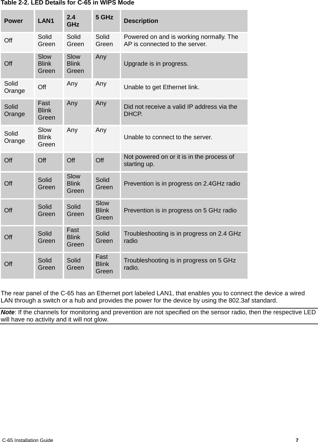
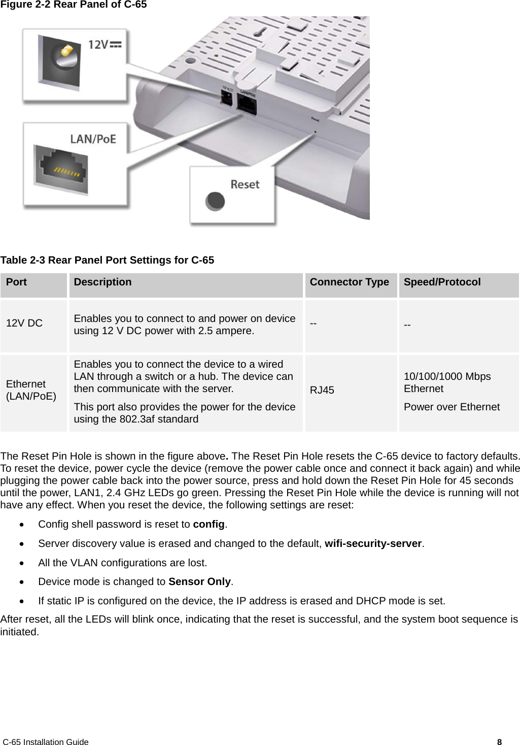
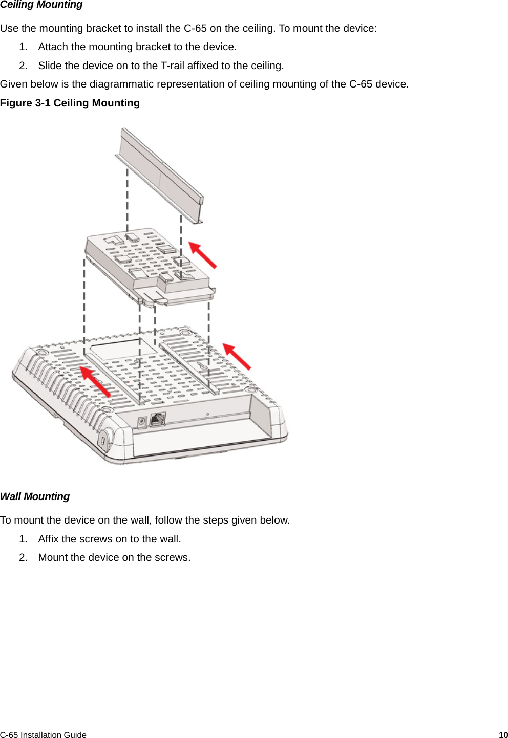
- 2. User Manual.pdf
- 3. User Guide rev
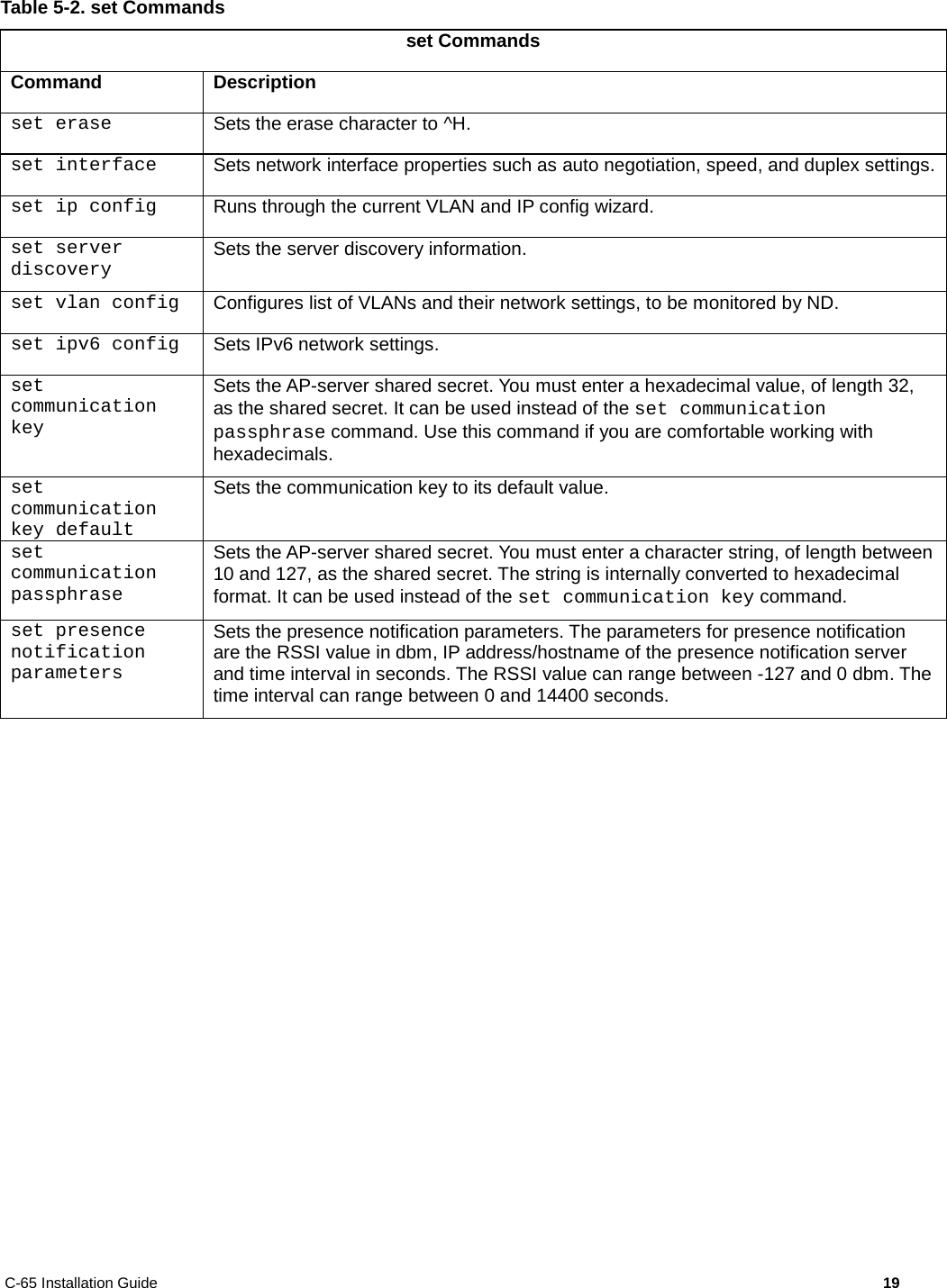
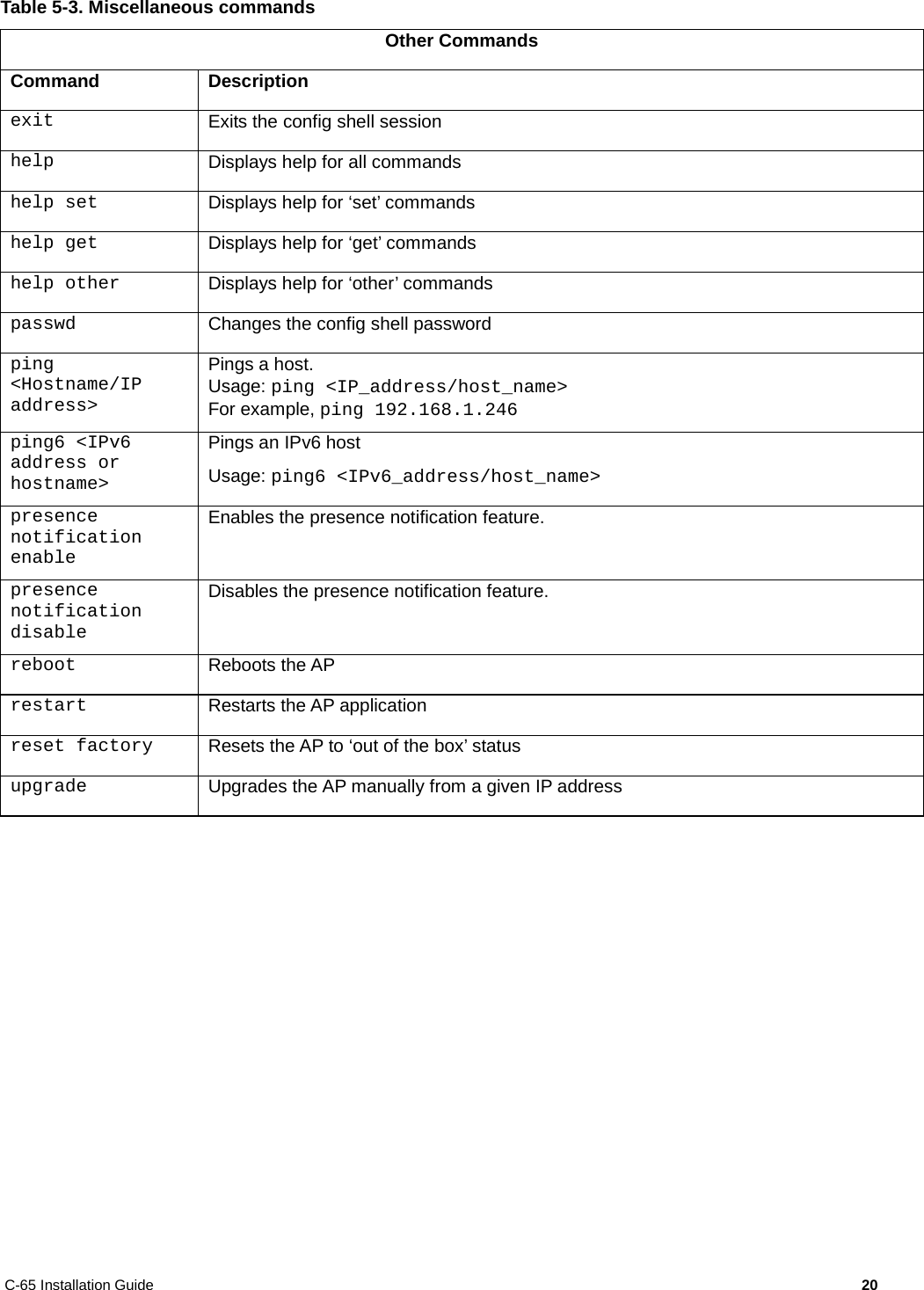
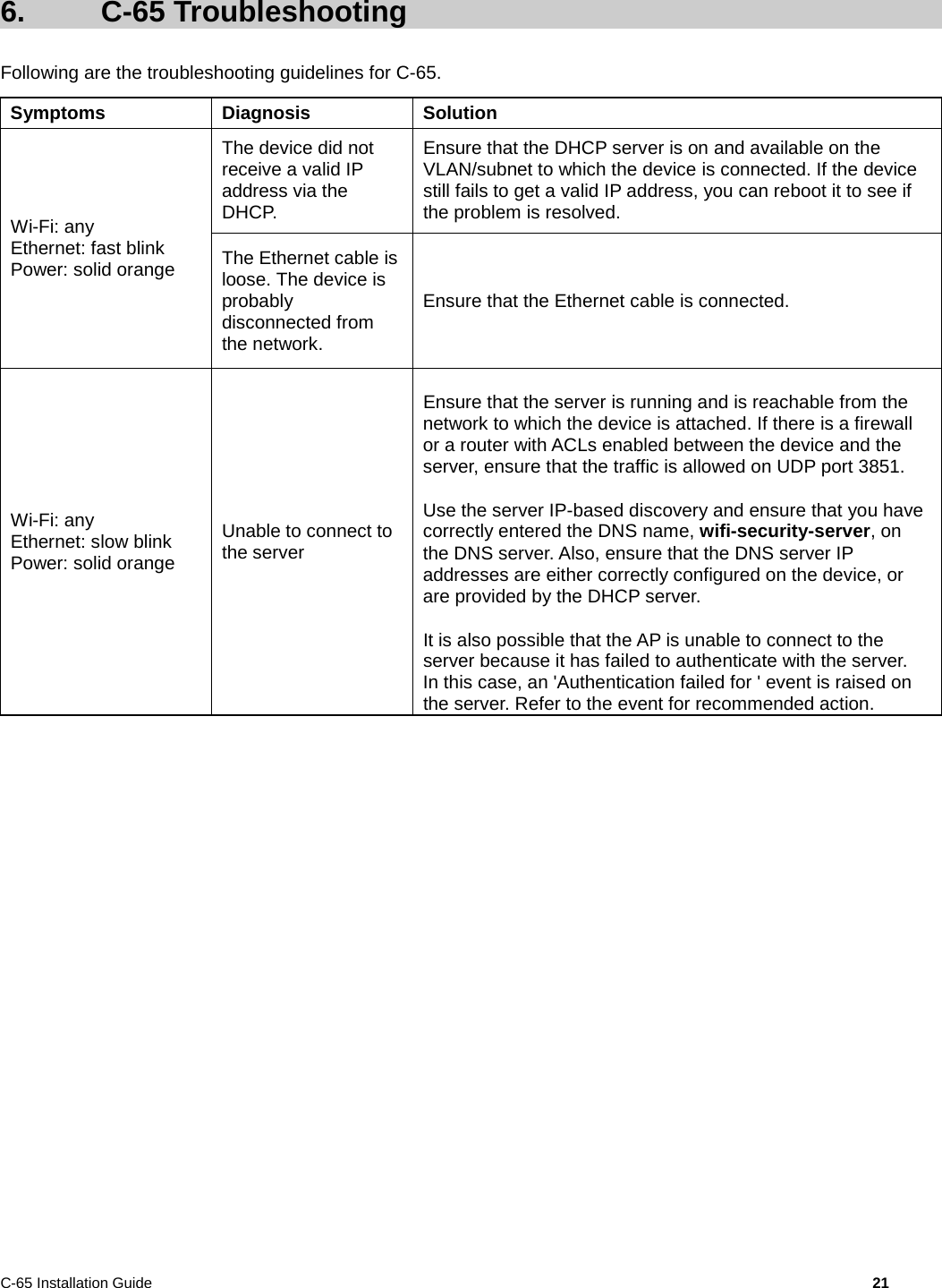
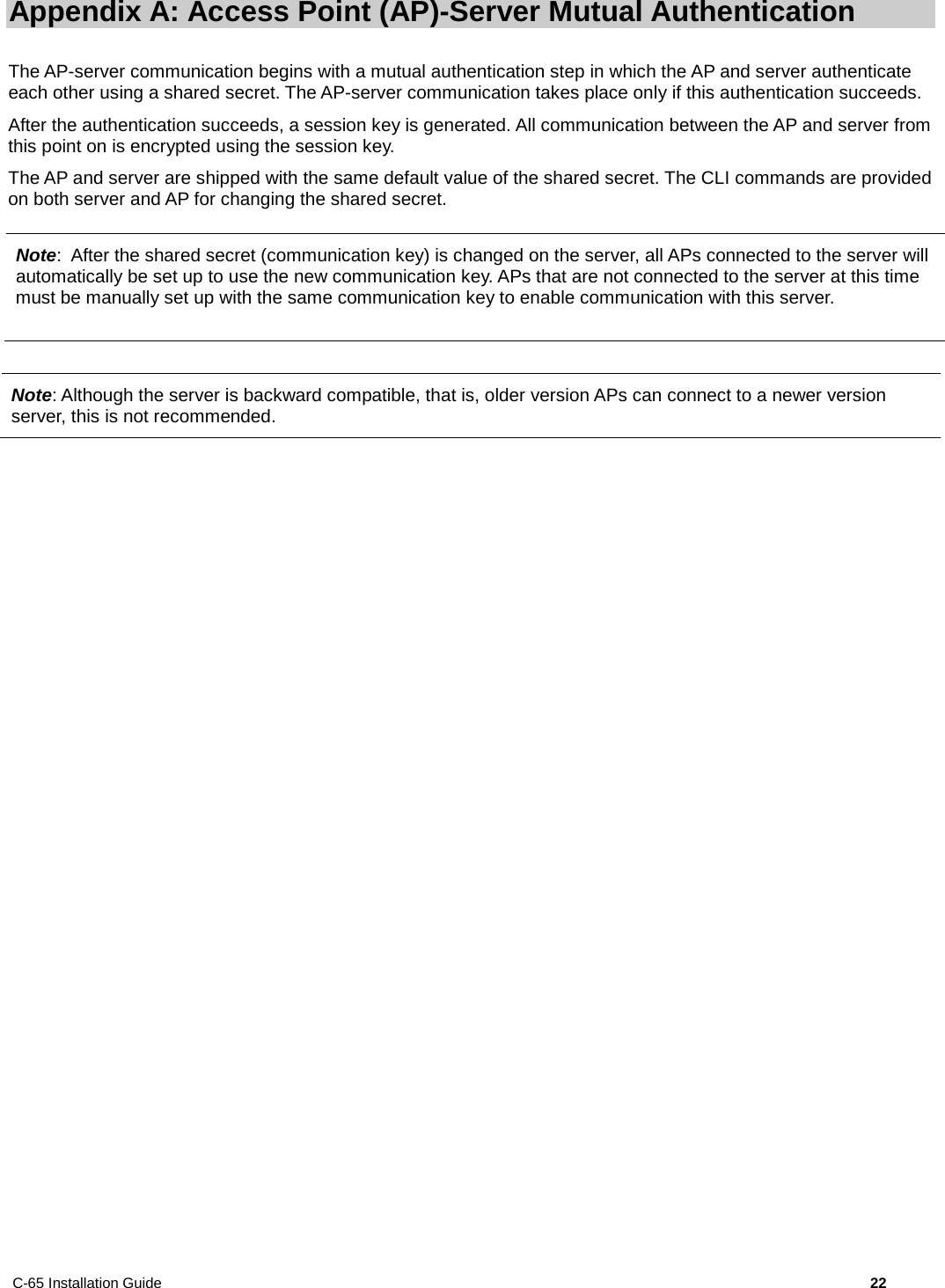
- 4. Professiona Installatio Guide rev
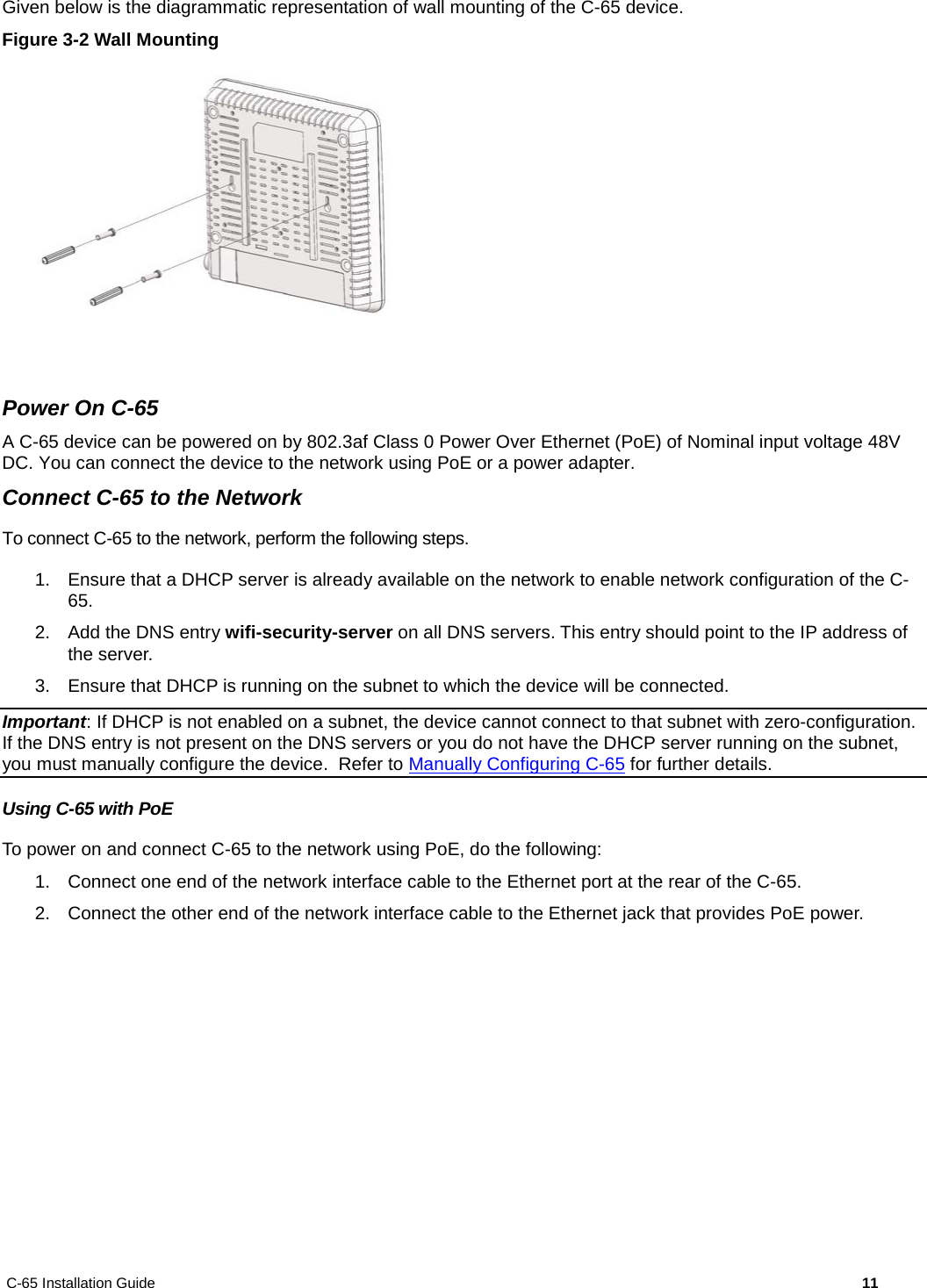
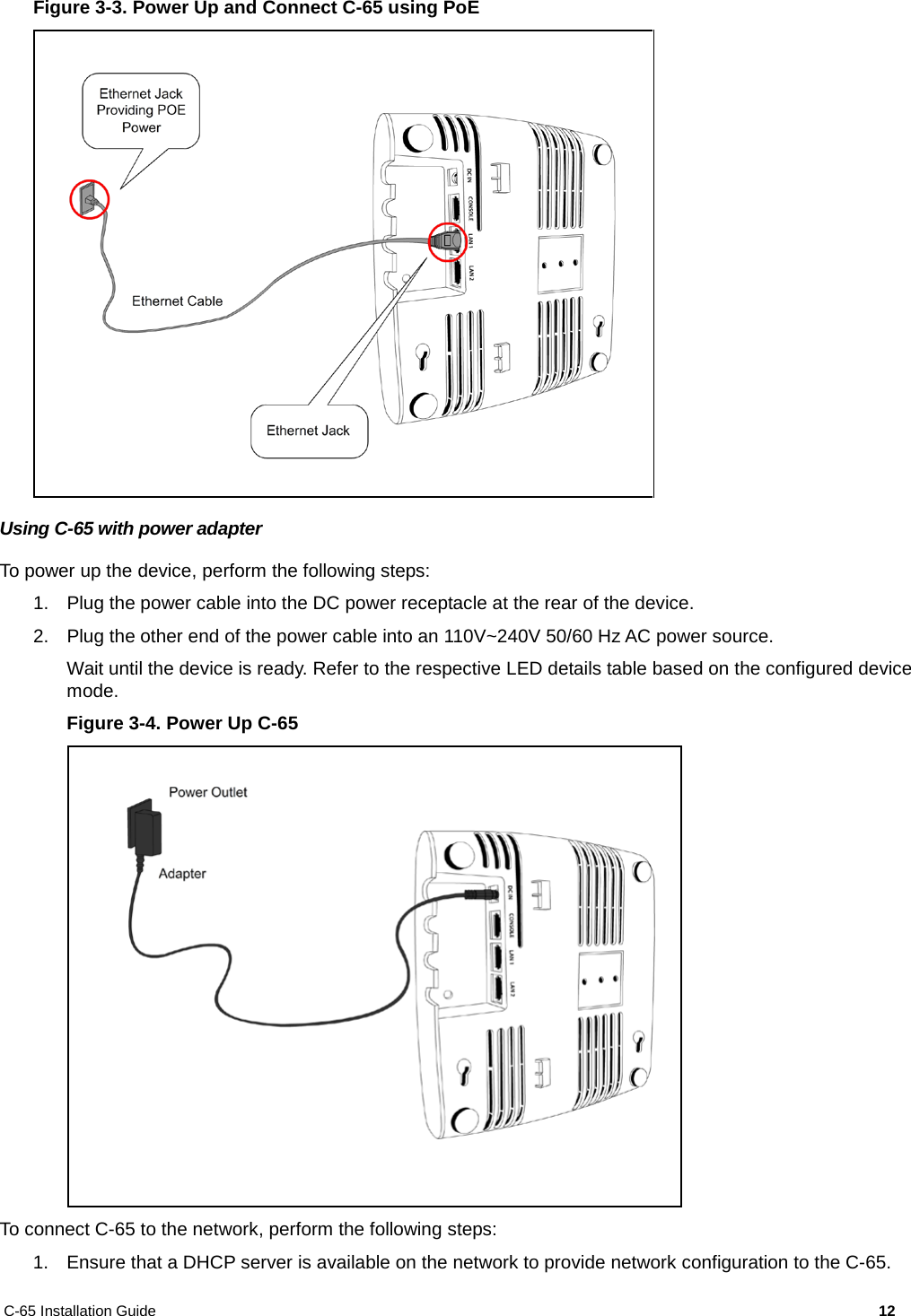
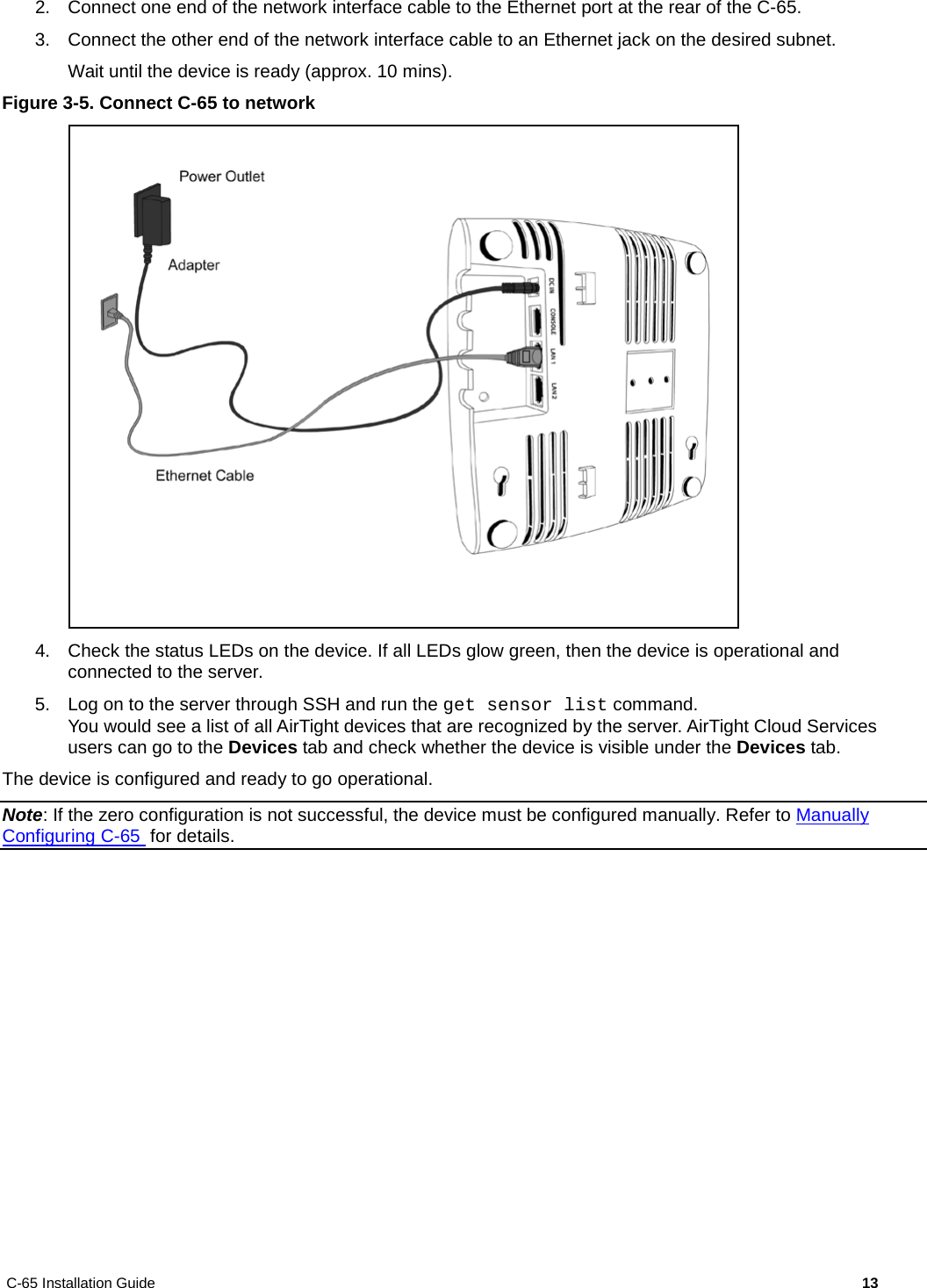
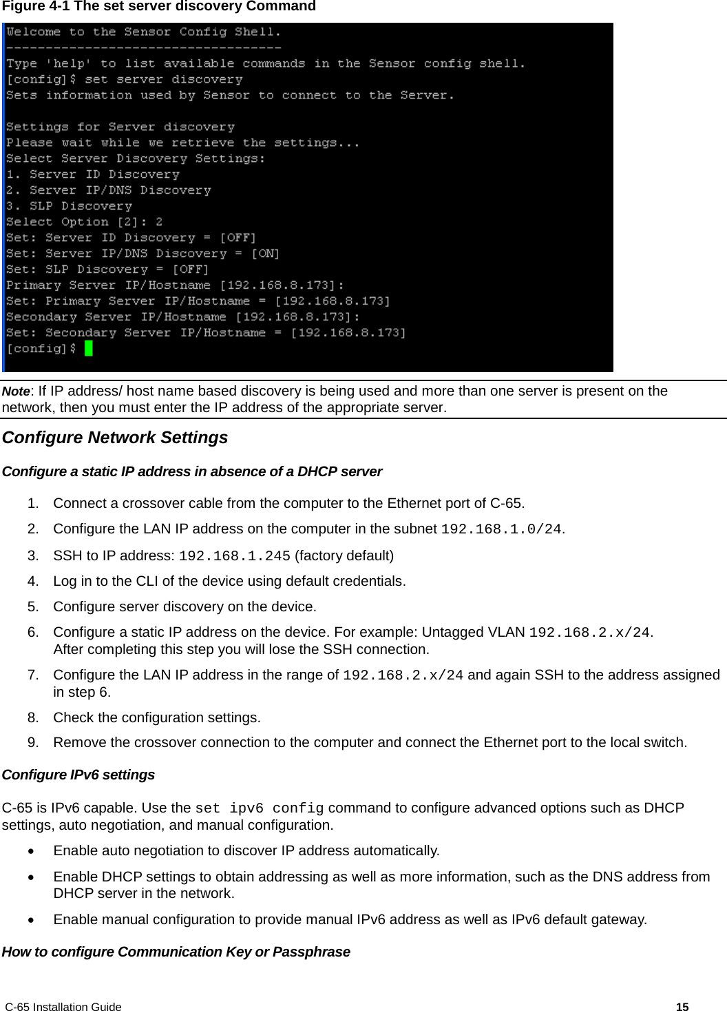
Professiona Installatio Guide rev