Arista Networks SS-200-AT 802.11a/b/g AP User Manual GUI 2 0 Venus
AirTight Networks, Inc. 802.11a/b/g AP GUI 2 0 Venus
Contents
- 1. Users Manual
- 2. User manual
- 3. User Manual
User manual

SpectraGuard Sensor
Installation Guide

Disclaimer
SpectraGuard Sensor Installation Guide
ii
THE INFORMATION IN THIS GUIDE IS SUBJECT TO CHANGE WITHOUT ANY PRIOR NOTICE.
AIRTIGHT NETWORKS, INC., IS NOT LIABLE FOR ANY SPECIAL, INCIDENTAL, INDIRECT, OR
CONSEQUENTIAL DAMAGES WHATSOEVER (INCLUDING, WITHOUT LIMITATION, DAMAGES FOR
LOSS OF BUSINESS PROFITS, BUSINESS INTERRUPTION, LOSS OF BUSINESS INFORMATION, OR ANY
OTHER PECUNIARY LOSS) ARISING OUT OF THE USE OF OR INABILITY TO USE THIS PRODUCT.
Limitation of Liability
AirTight Networks will not be liable to customer or any other party for any indirect, incidental,
special, consequential, exemplary, or reliance damages arising out of or related to the use of
SpectraGuard Sensor under any legal theory, including but not limited to lost profits, lost data, or
business interruption, even if AirTight knows of or should have known of the possibility of such
damages. Regardless of the cause of action or the form of action, AirTight's total cumulative
liability for actual damages arising out of or related to the use of SpectraGuard Sensor will not
exceed the price paid for SpectraGuard Sensor.
Copyright © 2003 – 2005 AirTight Networks, Inc. All rights reserved.
AirTight Networks, The AirTight logo, and SpectraGuard™ are trademarks of AirTight Networks,
Inc. All other products and services are trademarks, registered trademarks, and service marks or
registered service marks of their respective owners.
Intellectual Property Notice: One or more features and components in this product have patents
pending, which are owned by AirTight Networks, Inc.
Federal Communication Commission Interference Statement
This equipment has been tested and found to comply with the limits for a Class B digital device, pursuant to Part
15 of the FCC Rules. These limits are designed to provide reasonable protection against harmful interference in a
residential installation. This equipment generates, uses and can radiate radio frequency energy and, if not
installed and used in accordance with the instructions, may cause harmful interference to radio communications.
However, there is no guarantee that interference will not occur in a particular installation. If this equipment does
cause harmful interference to radio or television reception, which can be determined by turning the equipment off
and on, the user is encouraged to try to correct the interference by one of the following measures:
-Reorient or relocate the receiving antenna.
-Increase the separation between the equipment and receiver.
-Connect the equipment into an outlet on a circuit different from that
to which the receiver is connected.
-Consult the dealer or an experienced radio/TV technician for help.
This device complies with Part 15 of the FCC Rules. Operation is subject to the following two conditions: (1)
This device may not cause harmful interference, and (2) this device must accept any interference received,
including interference that may cause undesired operation.
FCC Caution: Any changes or modifications not expressly approved by the party responsible for compliance
could void the user's authority to operate this equipment.
IMPORTANT NOTE:
FCC Radiation Exposure Statement:
This equipment complies with FCC radiation exposure limits set forth for an uncontrolled environment. This
equipment should be installed and operated with minimum distance 20cm between the radiator & your body.
If this device is going to be operated in 5.15 ~ 5.25GHz frequency range, then it is restricted in indoor
environment only.
This transmitter must not be co-located or operating in conjunction with any other antenna or transmitter.

End User License Agreement
SpectraGuard Sensor Installation Guide
iii
End User License Agreement
This End User License Agreement (“EULA”) governs the terms and conditions of use of AirTight products. If a
Purchase Order has been issued by the Customer to AirTight for the use of this product, additional terms listed
in the Purchase Order will also apply. In the event of a conflict between this EULA and a Purchase Order, the
terms of the Purchase Order will prevail.
1. Definitions
Capitalized terms used in this EULA are defined in this Section 1 or the section in which they are first used.
1.1 “Customer” means an end-user or a business entity that purchases AirTight products and operates it
under the terms and conditions described in this agreement.
1.2 “AirTight” means AirTight Networks, Inc., AirTight Networks Private Limited or its related
companies and subsidiaries.
1.3 “Delivery” means delivery of the Hardware and Software.
1.4 “Documentation” means the standard end-user technical documentation and specifications that
AirTight supplies with the Hardware and Software. Advertising and marketing materials are not
Documentation.
1.5 “Error” means a reproducible failure of the Software or Hardware to perform in substantial
conformity with its Documentation.
1.6 "Hardware" means Sensor, Sentry, Appliance or any other hardware component provided by
AirTight.
1.7 “Intellectual Property Rights” means copyrights, trademarks, service marks, trade secrets, patents,
patent applications, moral rights, contractual rights of non-disclosure or any other intellectual property or
proprietary rights, however arising, throughout the world.
1.8 “Release” means any Update or Upgrade if and when these are made available by AirTight. In the
event of a dispute as to whether a particular Release is an Update or an Upgrade, AirTight's published
designation will be final.
1.9 “Software” means the software provided by AirTight to Customer (in object code format or loaded
on AirTight Hardware) and any Release thereto if and when such Releases are made available by AirTight.
1.10 “Update” means, if and when available, any error corrections, fixes, workarounds or other
maintenance releases in respect of the Software provided by AirTight to Customer that do not add additional
functionality to the Software.
1.11 “Upgrade” means, if and when available, new releases or versions of the Software, that materially
improve the functionality of, or add material functional capabilities to the Software and in respect of which
AirTight charges Customer additional license fees.
2. Terms of Sale
2.1 Scope. This EULA together with any Purchase Order(s) governs all transactions between the parties
with respect to the Hardware and Software provided by AirTight. This EULA does not require either party to
enter into such transactions, but together with the Purchase Order specifies the terms and conditions of such
transactions if and when they take place.
2.2 Software. All software provided by AirTight is licensed, not sold. Customer's right to use such
Software is subject to the license granted in Section 3 of this EULA.
2.3 Installation. Customer will be responsible for installing the Software and Hardware unless Customer
purchases Installation Services from AirTight pursuant to a separate Professional Services Agreement.
3. License Grant
3.1 Hardware and Software License. For each unit of Hardware and Software that is supplied to

End User License Agreement
SpectraGuard Sensor Installation Guide
iv
Customer, AirTight grants Customer a non-exclusive, non-transferable (except as provided in Section 9.5), non-
sub licensable license during the term of this EULA, to install and execute such Software and Hardware for
Customer's own business purposes. Each license is subject to the terms and conditions of this EULA, including
but not limited to this Section 3 and Customer's obligation to pay the applicable license fees for the use of such
Hardware and Software.
3.2 Restrictions on Use. Notwithstanding the license grant in Section 3.1, Customer may not: (a) use the
Software except as expressly permitted under Section 3.1; (b) separate the component programs of the Software
for use on different computers; (c) adapt, alter, publicly display, publicly perform, translate, create derivative
works of or otherwise modify the Software; (d) sublicense, lease, rent, loan, distribute or otherwise transfer the
Software to any third party (except as provided in Section 9.5); (e) reverse engineer, decompile, disassemble or
otherwise attempt to derive the source code for the Software except to the extent expressly permitted by
applicable law notwithstanding this restriction, to obtain information necessary to render the Software
interoperable with other software; provided, however, that Customer must first request such information from
AirTight and AirTight may, in its discretion, either provide such information to Customer or impose reasonable
conditions, including a reasonable fee, on such use of the source code for the Software to ensure that AirTight's
and its suppliers' proprietary rights in the source code for the Software are protected; (f) remove, alter or
obscure any proprietary notices on the Software or Documentation; (g) allow third parties to access or use the
Software, including but not limited to ASP, OEM or time-sharing arrangements. Under no circumstances may
Customer install or execute the Software on more than one computer at the same time; or (h) capture
screenshots of the Software and share it with other people without written consent of AirTight for any purpose
including but not limited to competitive analysis, copying or reverse engineering.
4. Term and Termination
4.1 Term. The term of this EULA will begin on the Effective Date and will continue indefinitely unless
terminated pursuant to this Section 4.
4.2 Termination for Cause. Either party may terminate this EULA for cause by giving the breaching party
written notice of termination, and specifying in such notice the alleged breach. The breaching party will have a
grace period of thirty (30) days after such notice is served to cure the breach described therein. If the breach is
cured within the thirty (30) day grace period, then this EULA will remain in effect. If the breach is not cured
within such period, then this EULA will automatically terminate upon the conclusion of the thirty (30) day
grace period, unless the parties agree in writing to extend such period.
4.3 Effects of Termination. Upon termination of this EULA for any reason: (a) all unfulfilled Purchase
Orders will be cancelled at AirTight's discretion; (b) any amounts owed to AirTight under this EULA and any
Purchase Order before such termination will be immediately due and payable; (c) all license rights granted in
this EULA will immediately terminate and Customer must promptly stop all use of the Software; (d) AirTight's
obligation to provide services under any Service Schedule attached to the Purchase Order terminates; (e)
Customer must erase all copies of the Software from Customer's computers, and destroy all copies of the
Software and Documentation on tangible media in Customer's possession or control or return such copies to
AirTight in accordance with Section 6.5; and (f) Customer must certify in writing to AirTight that it has
returned or destroyed such Software and Documentation. Sections 4.3, 5, 6.6, 7, 8 and 9 will survive the
expiration or termination of this EULA. The obligations under Section 8 will, however, survive only for claims
based on use of the Hardware or Software during the licensed term. Termination of this EULA will not affect
Customer's right to otherwise use or transfer the Hardware purchased from AirTight once Software is removed.
5. Proprietary Rights
Proprietary Rights. Customer acknowledges and agrees that the Software including but not limited to its
sequence, structure, organization and source code, contains Intellectual Property Rights of AirTight and its

End User License Agreement
SpectraGuard Sensor Installation Guide
v
suppliers, including without limitation valuable trade secrets. The Software is licensed and not sold to
Customer, and no title or ownership to such Software or the Intellectual Property Rights embodied therein
passes as a result of this EULA or any act pursuant to this EULA. The Software (and all Intellectual Property
Rights therein) is the exclusive property of AirTight and its suppliers, and all rights in and to the Software not
expressly granted to Customer in this EULA, are reserved. AirTight owns all copies of the Software, however
made. Nothing in this EULA will be deemed to grant, by implication, estoppels or otherwise, a license under
any of AirTight's existing or future patents (or the existing or future patents of its suppliers). The Software and
related materials contain trade secrets of AirTight and Customer will not disclose the Software, Documentation
or any other AirTight confidential and/or proprietary information to any third party.
6. Limited Warranties
6.1 Media. For the period of one (1) month after Delivery (as defined in Section 1.2 of the Purchase
Order) (the “Media Warranty Period”), AirTight warrants to and for the sole benefit of Customer that the media
on which the Software is provided to Customer will be free of defects in materials and workmanship.
Customer's exclusive remedy and AirTight's sole liability for breach of this warranty is that AirTight will, at its
own expense, replace any defective media returned to AirTight within the Media Warranty Period. This
warranty does not apply to damage resulting from misuse, abuse, or neglect.
6.2 Software. For the period of one (1) month after Delivery (as defined in Section 1.2 of the Purchase
Order) (the “Software Warranty Period”), AirTight warrants to and for the sole benefit of Customer that,
subject to Section 6.4, any Software, when used as permitted under this EULA and in accordance with the
instructions in the Documentation, will operate substantially without Error. Customer's exclusive remedy and
AirTight's sole liability for breach of this warranty is that AirTight will, at its own expense, use commercially
reasonable efforts to make available to Customer, by Internet download, Updates (that are intended to correct
such Errors) that AirTight makes generally available, for Errors reported to AirTight during the Software
Warranty Period. Any Error correction provided to Customer will not extend the original Software Warranty
Period.
6.3 Hardware. For the period of one (1) month after Delivery (as defined in Section 1.2 of the Purchase
Order) (the “Hardware Warranty Period”), AirTight warrants to and for the sole benefit of Customer that,
subject to Section 6.4, any Hardware sold to Customer will be free of substantial defects in materials and
workmanship. As Customer's exclusive remedy and AirTight's sole liability for breach of this warranty,
AirTight will, at its election, repair or replace any defective Hardware returned to AirTight (in accordance with
Section 6.5) within the Hardware Warranty Period. If AirTight is unable to repair or replace such Hardware,
then it will accept a return of such Hardware (in accordance with Section 6.5) and refund to Customer the price
paid by Customer for the Hardware. Any remedy provided under this Section 6.3 will not extend the original
Hardware Warranty Period.
6.4 Exclusions. AirTight will have no obligation under this EULA to correct, and AirTight makes no
warranty with respect to, Errors caused by: (a) improper installation of supported Software or Hardware; (b)
changes that Customer has made to supported Software or Hardware; (c) use of the supported Software or
Hardware in a manner inconsistent with the Documentation; (d) combination of supported Software and
Hardware with hardware or software not provided by AirTight; (e) malfunction, modification or relocation of
Customer's servers; or (f) Customer's failure to make reasonable backups.
6.5 Returns Procedure. To return an item of Hardware for any reason permitted under this EULA,
Customer must notify AirTight in writing or by fax of its proposed return, and request a tracking number.
AirTight will issue tracking numbers in accordance with its then-current standard procedures. Within ten (10)
days of receipt of the tracking number, Customer will return the relevant Hardware to AirTight (a) in
accordance with AirTight's return policies, procedures and instructions; (b) freight prepaid; and (c) in its
original shipping carton with the tracking number displayed on the outside of the carton. Customer bears the

End User License Agreement
SpectraGuard Sensor Installation Guide
vi
risk of loss or damage to any returned Hardware until such Hardware is received by AirTight at its premises.
AirTight reserves the right to refuse to accept any returned Hardware that does not bear a tracking number on
the outside of the carton or which otherwise does not comply with AirTight's return policies, procedures and
instructions.
6.6 Disclaimer. Except for the express warranties in Sections 6.1, 6.2, and 6.3, AirTight hereby disclaims
all other warranties, whether express, implied or statutory, including but not limited to the implied warranties
of merchantability, fitness for a particular purpose, accuracy, result, effort, title and non-infringement. There is
no warranty that the Software will be error free, or that the Software or Hardware will operate without
interruption or will fulfill any of Customer's particular purposes or needs.
7. Limitation of Liability
Limitation of Damages. AirTight will not be liable to Customer or any other party for any indirect, incidental,
special, consequential, exemplary or reliance damages arising out of or related to this EULA under any legal
theory, including but not limited to lost profits, lost data or business interruption, even if AirTight knows of or
should have known of the possibility of such damages. Regardless of the cause of action or the form of action,
AirTight's total cumulative liability for actual damages arising out of or related to this EULA relating to a
particular piece of Hardware or Software will not exceed the price paid for such Hardware and Software. The
limitations of this Section 7 will not apply to or otherwise limit AirTight's liability for indemnification claims
under Section 8. This Section 7 will apply even if an exclusive remedy of Customer hereunder has failed of its
essential purpose. Customer acknowledges that the prices and fees reflect the allocation of risk set forth in this
Agreement and that AirTight would not enter into this Agreement without these limitations on its liability.
8. Indemnification
8.1 AirTight's Obligation. Subject to Sections 8.2 and 8.3, AirTight will defend at its own expense any
action brought against Customer by a third party, to the extent that: (a) such action is based upon a claim that
the Hardware or Software infringes upon any U.S. copyrights or U.S. patents registered or issued as of the
Effective Date, or (b) that the negligence of AirTight personnel caused personal injury or property damage.
AirTight will pay those costs and damages finally awarded against Customer in any such action that are
specifically attributable to such claim, or those costs and damages agreed to in a monetary settlement of such
action. The foregoing obligations are conditioned on Customer: (a) notifying AirTight promptly in writing of
such action; (b) giving AirTight sole control of the defense thereof and any related settlement negotiations; and
(c) cooperating and, at AirTight's request and expense, assisting in such defense. Customer may also participate
in the defense at its own expense. This Section 8.1 states AirTight’s entire liability and Customer's sole and
exclusive remedy for any third-party claims.
8.2 Cure. If the Hardware or Software becomes, or in AirTight’s opinion is likely to become, the subject
of an infringement claim that AirTight is required to defend pursuant to Section 8.1, then AirTight may (at its
option and expense) either: (a) procure for Customer the right to continue using the Hardware or Software; or
(b) replace or modify the Hardware or Software so that it becomes non-infringing. If neither of the foregoing
options is reasonably available, then AirTight may: (i) terminate Customer's rights hereunder to use the
Software; and (ii) refund a pro-rata portion of any price Customer paid under this EULA, based on the useful
life of the Hardware and Software upon return of same to AirTight. Solely for the purpose of calculating any
refund payable to Customer under this Section 8.2, the parties agree that the useful life of the Hardware and
Software will be deemed to be two (2) years.
8.3 Exclusions. Notwithstanding the foregoing, AirTight will have no obligation under this Section 8 or
otherwise with respect to any infringement claim based upon: (a) any use of the Hardware or Software not in
accordance with this EULA or the Documentation: (b) any use of the Hardware or Software in combination
with other products, Hardware, software, or data not provided or approved by AirTight; (c) any use of any

End User License Agreement
SpectraGuard Sensor Installation Guide
vii
Release of the Software other than the most current Release made available to Customer; or (d) any
modification of the Hardware or Software by any person other than AirTight or its authorized agents.
Customer will indemnify AirTight against all liability, damages and costs (including but not limited to
reasonable attorneys' fees) resulting from or related to such a claim.
8.4 AirTight products may be capable of operating at frequencies beyond those allowed in your region.
You must indemnify, hold harmless, and defend AirTight from and against all Legal and Statutory obligations
if you choose to operate the SpectraGuard Enterprise products beyond the allowed frequencies.
9. General
9.1 Notices. All notices, consents and approvals under this EULA (other than orders and order
acknowledgments) must be delivered in writing by courier, by facsimile or by certified or registered mail
(postage prepaid and return receipt requested) to the other party at the address set forth above, and will be
effective upon receipt or three (3) business days after being deposited in the mail as required above, whichever
occurs sooner. Either party may change its address by giving notice of the new address to the other party.
9.2 No Third-Party Beneficiaries. No party will be deemed a third-party beneficiary to this EULA.
9.3 Relationship of Parties. The parties hereto are independent contractors. Nothing in this EULA will be
deemed to create an agency, employment, partnership, fiduciary or joint venture relationship between the
parties.
9.4 Compliance with Export Control Laws. The Software will only be delivered to Customer in the
United States and may be subject to export control regulations of the United States and other countries, with
which Customer will comply.
9.5 Assignments. Customer may not assign or transfer, by operation of law, merger or otherwise, any of
its rights or delegate any of its duties under this EULA (including without limitation, its licenses with respect to
the Software) to any third party without AirTight’s prior written consent. Any attempted assignment or
transfer in violation of the foregoing will be void. AirTight may assign its rights or delegate its obligations
under this EULA.
9.6 U.S. Government End Users. The Software and any other software covered under this EULA, are
“commercial items” as that term is defined at 48 C.F.R. 2.101, consisting of “commercial computer software”
and “commercial computer software documentation” as such terms are used in 48 C.F.R. 12.212. Consistent
with 48 C.F.R. 12.212 and 48 C.F.R. 227.7202-1 through 227.7202-4, all U.S. Government end users acquire the
Software and any other software and documentation covered under this EULA with only those rights set forth
therein.
9.7 Governing Law and Venue. This EULA will be governed by the laws of the State of California. The
United Nations Convention on Contracts for the International Sale of Goods does not apply to this EULA. Any
action or proceeding arising from or relating to this EULA must be brought exclusively in a federal or state
court seated in Santa Clara, California, and in no other venue. Each party irrevocably consents to the personal
jurisdiction and venue in, and agrees to service of process issued by, any such court. Notwithstanding the
foregoing, AirTight reserves the right to file a suit or action in any court of competent jurisdiction as AirTight
deems necessary to protect its intellectual property and proprietary rights.
9.8 Force Majeure. Any delay in or failure of performance by either party under this EULA, other than a
failure to pay amounts when due, will not be considered a breach of this EULA and will be excused to the
extent caused by any occurrence beyond the reasonable control of such party.
9.9 Remedies. Except as provided in Sections 6, 7 and 8, the parties' rights and remedies under this EULA
are cumulative. Customer acknowledges that the Software contains valuable trade secrets and proprietary
information of AirTight, that any actual or threatened disclosure or misapplication of such Software will
constitute immediate, irreparable harm to AirTight for which monetary damages would be an inadequate
remedy, and that injunctive relief is an appropriate remedy for such breach. If any legal action is brought to

End User License Agreement
SpectraGuard Sensor Installation Guide
viii
enforce this EULA, the prevailing party will be entitled to receive its attorneys' fees, court costs, and other
collection expenses, in addition to any other relief it may receive.
9.10 Waivers and Modifications. All waivers must be in writing. Any waiver or failure to enforce any
provision of this EULA on one occasion will not be deemed a waiver of any other provision or of such
provision on any other occasion. This EULA may be amended only by a written document signed by both
parties.
9.11 Severability. If any provision of this EULA is adjudicated to be unenforceable, such provision will be
changed and interpreted to accomplish the objectives of such provision to the greatest extent possible under
applicable law and the remaining provisions will continue in full force and effect.
9.12 Entire EULA. This EULA, the Purchase Order(s) and Services Agreement(s) constitute the entire
agreement between the parties regarding the subject hereof and supersedes all prior or contemporaneous
EULAs, understandings, and communication, whether written or oral.
9.13 Counterparts. This EULA may be executed in counterparts, each of which will be considered.
The installation must be executed by technical staff.
The Access Point comes with five optional antennas:
Antenna 1-Omnidirectional antenna / Max Gain:12.0 dBi / 2.4 GHz
Antenna 2-Omnidirectional antenna / Max Gain:10.5 dBi / 2.4 GHz
Antenna 3-Omnidirectional antenna / Max Gain:5.2 dBi / 2.4 GHz
Antenna 4-Omnidirectional Panel antenna / Max Gain:3.0 dBi / 2.4 GHz and 5 GHz
Antenna 5-Omnidirectional antenna / Max Gain:6.0 dBi / 5 GHz
Antenna 6-Dual Band Omni antenna / Max Gain:6dBi/2.4GHz / 6.5dBi/5GHz
Operating Band for 3 conditions as below:
1. This AP with 5.2dBi / 10.5dBi / 12.0dBi antenna can be operated on frequency 2400-2483.5MHz & the output power
will be set on 20dBm
2. This AP with 3.0dBi antenna can be operated on frequency 2400-2483.5MHz/5150-5350 /5725-5850MHz & the
output power will be set on 2400-2483.5MHz : 22dBm , 5150-5350 : 13dBm ,5725-5850MHz : 20dBm
3This AP with 6dBi antenna can be operated on frequency 5150-5350MHz/ 5725-5850MHz & the output power will
be set on 5150-5350MHz: 12dBm , 5725-5850 : 20dBm
**5150~5250MHz can’t be operated when outdoor use.
4.This AP with Dual Band Omni antenna (Gain:6dBi/2.4GHz / 6.5dBi/5GHz) can be operated on frequency
2400-2483.5MHz/5150-5350/5725-5850MHz & the output power will be set on 2400-2483.5MHz : 22dBm.
5150-5350 : 13dBm, 5725-5850MHz : 20dBm

Table of Contents
SpectraGuard Sensor Installation Guide
ix
Table of Contents
CHAPTER 1 PREFACE.............................................................................................................................1
1.1 BEFORE YOU BEGIN .......................................................................................................1
1.2 HOW TO GET MORE INFORMATION..................................................................................1
CHAPTER 2 PACKAGE CONTENTS.....................................................................................................2
CHAPTER 3 OVERVIEW.........................................................................................................................3
3.1 PORT AND POWER CONNECTIONS...................................................................................3
3.2 STATUS LEDS...............................................................................................................4
CHAPTER 4 INSTALLING SPECTRAGUARD SENSOR....................................................................7
4.1 CONNECTING POWER.....................................................................................................7
4.2 CONNECTING TO THE NETWORK ....................................................................................8
CHAPTER 5 MANUAL CONFIGURATION OF SPECTRAGUARD SENSOR...............................10
5.1 INTRODUCTION............................................................................................................10
5.2 MANUAL CONFIGURATION OF SPECTRAGUARD SENSOR ..............................................10
5.3 CONFIGURING SPECTRAGUARD SENSOR THROUGH WEB INTERFACE (HTTP).................11
5.3.1 Step1: Log into the Web Interface................................................................11
5.3.2 Step 2: Change Password Settings...............................................................12
5.3.3 Step 3: Change Network Settings .................................................................13
5.3.4 Step 4: Change Discovery Settings...............................................................15
5.4 CONFIGURING SPECTRAGUARD SENSOR THOUGH COMMAND LINE INTERFACE (CLI)...17
5.4.1 Step 1: Invoking the Command Line Interface .............................................17
5.4.2 Step 2: Log into the Command Line Interface and change password ..........20
5.4.3 Step 3: Change Network Settings .................................................................21
5.4.4 Step 4: Change Discovery Settings...............................................................24
5.4.5 Other Commands..........................................................................................25
CHAPTER 6 TROUBLESHOOTING ....................................................................................................29

Table of Figures
SpectraGuard Sensor Installation Guide
x
Table of Figures
FIGURE 1 PACKAGE CONTENTS...................................................................................................................2
FIGURE 2 REAR PANEL OF SPECTRAGUARD SENSOR SHOWING PORT AND POWER CONNECTIONS ..................3
FIGURE 3 FRONT PANEL OF SPECTRAGUARD SENSOR SHOWING THE LEDS..................................................4
FIGURE 4 SPECTRAGUARD SENSOR SHOWING POWER CONNECTIONS ...........................................................7
FIGURE 5 SPECTRAGUARD SENSOR SHOWING NETWORK AND POWER CONNECTIONS ..................................8
FIGURE 6 CONNECTING TO SPECTRAGUARD SENSOR USING THE CROSSOVER CABLE.................................11
FIGURE 7 LOGIN SCREEN ..........................................................................................................................12
FIGURE 8 PASSWORD SETTINGS SCREEN ...................................................................................................13
FIGURE 9 REBOOT SCREEN .......................................................................................................................13
FIGURE 10 NETWORK SETTINGS SCREEN ....................................................................................................14
FIGURE 11 DISCOVERY SETTINGS SCREEN ..................................................................................................16
FIGURE 12 CONNECTING TO SPECTRAGUARD SENSOR USING THE SERIAL CABLE ........................................17
FIGURE 13 OPENING HYPERTERMINAL .......................................................................................................18
FIGURE 14 NEW HYPERTERMINAL CONNECTION ........................................................................................19
FIGURE 15 HYPERTERMINAL CONNECTION DETAILS...................................................................................19
FIGURE 16 HYPERTERMINAL PORT SETTINGS .............................................................................................20
FIGURE 17 CHANGING PASSWORD USING THE PASSWD COMMAND ...............................................................21
FIGURE 18 CHANGING NETWORK SETTINGS USING THE SETDHCPIP COMMAND..............................................22
FIGURE 19 CHANGING NETWORK SETTINGS USING THE SETSTATICIP COMMAND ...........................................24
FIGURE 20 CHANGING DISCOVERY SETTINGS USING THE EDITCONFIG COMMAND ........................................25
FIGURE 21 VIEWING NETWORK SETTINGS USING THE VIEWIP COMMAND ......................................................25
FIGURE 22 VIEWING THE CURRENT CONFIGURATION SETTINGS USING THE VIEWCONFIG COMMAND..............26
FIGURE 23 RESETTING TO FACTORY DEFAULT SETTINGS USING THE RESETFACTORY COMMAND ...................27
FIGURE 24 STATUS COMMAND ....................................................................................................................27
FIGURE 25 VER COMMAND ..........................................................................................................................27
FIGURE 26 PING COMMAND.........................................................................................................................27
FIGURE 27 SENSORD_RESTART COMMAND ..................................................................................................28
FIGURE 28 EXIT COMMAND .........................................................................................................................28
FIGURE 29 HELP COMMAND ........................................................................................................................28

Preface
SpectraGuard Sensor Installation Guide
1
Chapter 1 Preface
1.1 Before you begin
Thank you for purchasing SpectraGuard Sensor (also referred to as Sensor). SpectraGuard Sensor
works in conjunction with a SpectraGuard Enterprise Server to provide an air-tight cover to your
corporate network. It monitors the 802.11 a/b/g medium and provides information to the
SpectraGuard Enterprise Server.
Please read the EULA before installing the Sensor. Installing SpectraGuard Sensor constitutes your
acceptance of the terms and conditions of the EULA mentioned above in this document. This
product cannot be rented or leased—you are the sole owner of the product.
This installation guide provides information about installation, initial configuration, and starting of
the SpectraGuard Sensor. This guide contains the following chapters:
Package Contents: This chapter describes the components of the package that come with this
installation guide. These components are required to successfully install SpectraGuard Sensor
on the network.
Overview: This chapter provides an overview of the SpectraGuard Sensor, ports and power
connectors.
Installing SpectraGuard Sensor: This chapter details how to install SpectraGuard Sensor
automatically. It also describes how to quickly power up the device and connect it to the
network.
Configuring SpectraGuard Sensor: This chapter describes the configuration of SpectraGuard
Sensor using Web Interface (http) and the Command Line Interface (CLI).
Troubleshooting: This chapter provides troubleshooting tips for SpectraGuard Sensor
installation.
1.2 How to get more information
To receive important news on product updates, please visit our website at:
http://www.airtightnetworks.net.
You can also reach us by email at support@airtightnetworks.net.
Package Contents
SpectraGuard Sensor Installation Guide
2
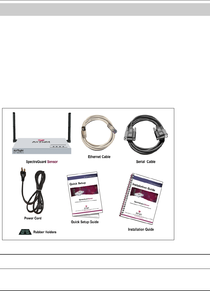
Chapter 2 Package Contents
This chapter gives you a list of the product package contents. Please make sure that the following
contents form a part of the SpectraGuard Sensor package. If the package is not complete, please
contact AirTight Networks, Inc., or return the package to the vendor or dealer where you
purchased it. The contents of the Sensor package are described below:
SpectraGuard Sensor
SpectraGuard Sensor Installation Guide
SpectraGuard Sensor Quick Setup Guide
Ethernet Cable
Serial Cable (optional)
Power Cord
Rubber Holders (optional)
Figure 1 Package Contents
Note: The MAC address for SpectraGuard Sensor is shown on a label at the bottom of the product and the
packaging box.
Overview
SpectraGuard Sensor Installation Guide
3
Chapter 3 Overview
This chapter provides an overview of the SpectraGuard Sensor and describes in detail about the
following:
Port and Power Connections
Status LEDs
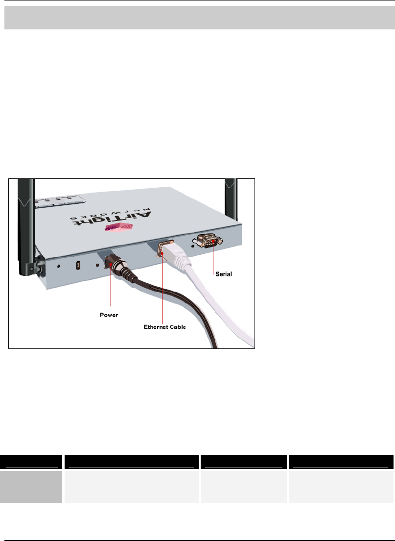
3.1 Port and Power Connections
The rear panel of the SpectraGuard Sensor has port and power connectors that enable you to power
up the device and connect it to the network or a computer.
Figure 2 Rear panel of SpectraGuard Sensor showing port and power connections
The SpectraGuard Sensor includes the following ports:
A Serial port for connecting to serial terminal emulation programs such as Hyper Terminal for
Windows or minicom for Linux.
An Ethernet port for connecting the device to the network.
Table 1 Rear Panel Port Settings
Port Description Connector Type Speed/Protocol
Serial Enables a serial connection to
establish terminal sessions.
Used for launching Command
DB-9 Bits per second: 9600
Data Bits: 8
Overview
SpectraGuard Sensor Installation Guide
4
Line Interface (CLI) sessions. Parity: None
Stop Bits: 1
Flow Control: None
Ethernet This enables the device to be
connected to the wired LAN
through a switch or a hub. This
connection allows the
SpectraGuard Sensor to
communicate with the
SpectraGuard Enterprise
Server.
RJ-45 10/100 Mbps/Ethernet
Note: The Connection settings mentioned in Table 1 above are the same for Hyper Terminal and minicom.
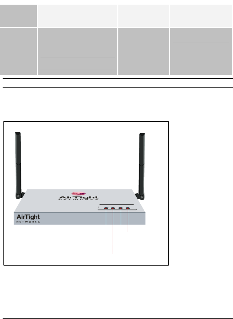
3.2 Status LEDs
The front panel of the SpectraGuard Sensor has Status LEDs that indicate the working of the
SpectraGuard Sensor.
LED1: Power
LED2: LAN
LED3: 802.11 a
LED4:802.11 b/g
LED1: Power
LED2: LAN
LED3: 802.11 a
LED4:802.11 b/g
Figure 3 Front panel of SpectraGuard Sensor showing the LEDs
These LEDs are described in Table 2 below:

Overview
SpectraGuard Sensor Installation Guide
5
Table 2 LED details
LED LED Color Meaning of LED
Solid Green This indicates that the Sensor is receiving power and is
working normally. There are no errors. Check LED2,
LED3, and LED4 to determine the status of the device.
Solid Yellow This indicates that the Sensor has encountered an error.
Check LED2, LED3, and LED4 to determine the error.
LED1
or
Power
Off This indicates that the Sensor is not receiving power.
Solid Green If LED1 is green, it indicates that the Sensor is
connected to the Ethernet and is able to connect to the
SpectraGuard Enterprise Server.
If LED1 is yellow, it indicates that the Sensor is unable
to connect to the Ethernet.
Fast Blinking Green
If LED1 is green, it indicates an invalid state that should
not occur. Try restarting the Sensor. If the problem
persists, please contact support@airtightnetworks.net.
If LED1 is yellow, it indicates that the Sensor did not get
a valid IP address from the Dynamic Host Configuration
Protocol (DHCP) Server. You can use the Command Line
Interface to configure the IP address of the
SpectraGuard Sensor.
Slow Blinking
Green
If LED1 is green, it indicates an invalid state that should
not occur.
If LED1 is yellow, it indicates that the Sensor got a valid
IP address from the DHCP Server but was unable to
connect to the SpectraGuard Enterprise Server.
LED2
or
LAN
Off If LED1 is green, it indicates an invalid state that should
not occur. Try restarting the Sensor. If the problem
persists, please contact support@airtightnetworks.net.
Solid Green If LED1 is green, it indicates that the Sensor is scanning
successfully on 802.11a (5 GHz frequency band).
If LED1 is yellow, it indicates that the Sensor is
experiencing an error on (802.11a/b/g) wireless
interfaces.
LED3
or
802.11a
Slow Blinking
Green
If LED1 is green, it indicates that the Sensor is
defending the network against a rogue connection on
the 802.11a (5 GHz frequency band).
If LED1 is yellow, it indicates an invalid state that should
not occur.

Overview
SpectraGuard Sensor Installation Guide
6
Off If LED1 is green, it indicates an invalid state that should
not occur. Try restarting the Sensor. If the problem
persists, please contact support@airtightnetworks.net.
Solid Green If LED1 is green, it indicates that the Sensor is scanning
successfully on 802.11b/g (2.4 GHz frequency band).
If LED1 is yellow, it indicates that the Sensor is
experiencing a software related error. This could be
related to the Sensor software that connects to the
SpectraGuard Enterprise Server.
Slow Blinking
Green
If LED1 is green, it indicates that the Sensor is
defending the network against a rogue connection on
802.11b/g (2.4 GHz frequency band).
If LED1 is yellow, it indicates an invalid state that should
not occur. Try restarting the Sensor. If the problem
persists, please contact support@airtightnetworks.net.
LED4
or
802.11b/g
Off If LED1 is green, it indicates an invalid state that should
not occur. Try restarting the Sensor. If the problem
persists, please contact support@airtightnetworks.net.
Installing SpectraGuard Sensor
SpectraGuard Sensor Installation Guide
7
Chapter 4 Installing SpectraGuard Sensor
SpectraGuard Sensor is the probe that monitors your network and communicates with the
SpectraGuard Enterprise Server to guard your corporate network against over-the-air attacks. The
Sensor must be plugged to your corporate network to perform the above operations.
Installing and configuring the SpectraGuard Sensor on the network is automatic. This chapter
discusses two simple steps to install the SpectraGuard Sensor:
1. Connecting Power
2. Connecting to the Network
Important! To prevent abuse and intrusion by unauthorized personnel, it is extremely important to install
the SpectraGuard Sensor such that it is difficult to unplug the device from the network or from the power
outlet.
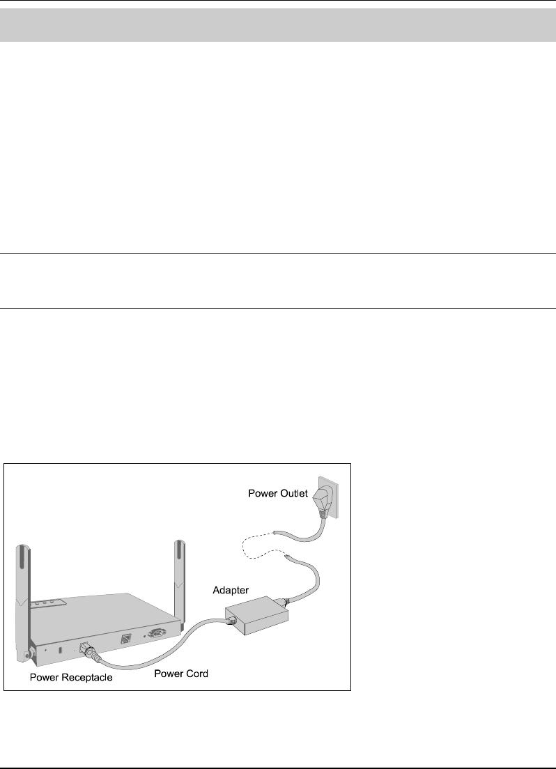
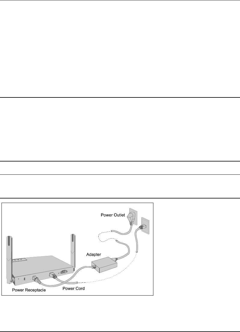
4.1 Connecting Power
SpectraGuard Sensor runs on a 5V DC connection. Use the power adapter provided to power the
SpectraGuard Sensor from a 110V˜240V 50/60 Hz AC power connection.
To connect the power to SpectraGuard Sensor, perform the following steps:
1. Plug the power cable into the DC power receptacle at the rear of the SpectraGuard Sensor.
2. Plug the other end of the power cable into an 110V˜240V 50/60 Hz AC power source.
Figure 4 SpectraGuard Sensor showing power connections
Caution : The installation must be executed by technical staff.
Installing SpectraGuard Sensor
SpectraGuard Sensor Installation Guide
8
Wait for two minutes!
Check the Status LEDs. You will see LED1 turn yellow and LED2 turn green. This means that
SpectraGuard Sensor is powered on correctly, and is waiting to be connected to the network.
4.2 Connecting to the Network
Ensure that the SpectraGuard Enterprise Server is already running on your network.
To connect SpectraGuard Sensor to the network, perform the following steps:
1. Connect one end of the Ethernet cable to the Ethernet port at the rear of the SpectraGuard
Sensor.
2. Connect the other end of the Ethernet cable to an Ethernet jack that is connected to a hub
or a switch.
Recommended! Carefully choose the network segment on which the SpectraGuard Sensor is connected. The
SpectraGuard Sensor should be placed on a network segment that can communicate with the SpectraGuard
Enterprise Server via multicast.
If you are placing the SpectraGuard Sensor across a router boundary that separates it from the SpectraGuard
Enterprise Server, ensure that multicast routing is enabled for the Multicast Group Address 224.0.23.11 on
this router. This Multicast Group Address is reserved by IANA for AirTight Networks, Inc. If your system
administrator does not allow multicast on routers, you must configure SpectraGuard Sensor manually. Refer
to Chapter 5 for details.
Important! If you connect the SpectraGuard Sensor to a network segment where a DHCP Server is
running, it will automatically receive an IP address. Otherwise, you will have to configure the IP address of
the SpectraGuard Sensor manually.
Figure 5 SpectraGuard Sensor showing Network and Power Connections

Installing SpectraGuard Sensor
SpectraGuard Sensor Installation Guide
9
Wait for two minutes!
Check the Status LEDs. If all LEDs glow green, then the SpectraGuard Sensor is operational and
connected to the SpectraGuard Enterprise Server.
The SpectraGuard Sensor is configured and ready to go. Check your SpectraGuard Enterprise
Console to ensure that this SpectraGuard Sensor has been detected.
You need not read this installation guide further.
Note: If LED1 turns yellow, it means that the automatic installation was not successful and the
SpectraGuard Sensor must be configured manually. Refer to Chapter 5 for details.
Note: If LED1 is green, then LED2, LED3, and LED4 must be solid green or blinking green. If this does not
happen, there is an error in one of the interfaces. Contact support@airtightnetworks.net for details.

Manual Configuration of SpectraGuard Sensor
SpectraGuard Sensor Installation Guide
10
Chapter 5 Manual Configuration of
SpectraGuard Sensor
Important! If the installation in Chapter 4 was successful, stop! You do not need to configure SpectraGuard
Sensor manually.
In this chapter you will learn how to manually configure SpectraGuard Sensor. The Sensor can be
configured in two ways:
Through the Web Interface (http)
Through the Command Line Interface (CLI)
You can choose either method to configure the SpectraGuard Sensor. The Web Interface is the
easiest way to configure the SpectraGuard Sensor. If you are comfortable using a HyperTerminal or
minicom console, you can also use the Command Line Interface method.
5.1 Introduction
You must configure and set up SpectraGuard Sensor manually if LED1 turns yellow during
automatic installation. This means that the Sensor was unable to connect to the SpectraGuard
Enterprise Server automatically. Manual configuration is required to set up the Sensor to
communicate with the SpectraGuard Enterprise Server. Manual configuration is typically required
in the following cases:
1. SpectraGuard Sensor did not get an IP address automatically from the DHCP Server.
2. SpectraGuard Sensor is placed on a network segment that is separated from SpectraGuard
Enterprise Server by a firewall. You must first open port 3851 for User Datagram Protocol
(UDP) and Transport Control Protocol (TCP) bidirectional traffic on that firewall. This
port number is assigned to AirTight Networks.
3. SpectraGuard Sensor is separated from SpectraGuard Enterprise Server by a router, a
Network Address Translation (NAT) device or a firewall that does not have multicast
enabled.
5.2 Manual Configuration of SpectraGuard Sensor
The following steps are used to configure SpectraGuard Sensor:
1. Log in
2. Change Password Settings
3. Change Network Settings
Manual Configuration of SpectraGuard Sensor
SpectraGuard Sensor Installation Guide
11
4. Change Discovery Settings
Manual configuration can be done through a Web Interface (http) or Command Line Interface
(CLI).
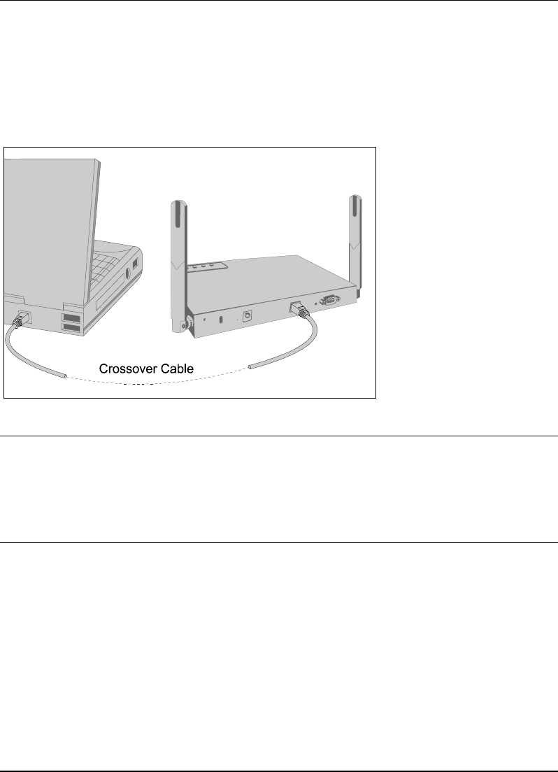
5.3 Configuring SpectraGuard Sensor through Web Interface (http)
Configuration using Web Interface is done using the network connection or using the crossover
cable connected between your machine and the Sensor.
Figure 6 Connecting to SpectraGuard Sensor using the Crossover Cable
Important! For Web configuration using the crossover cable, make sure that your machine is not running a
DHCP Server. You can figure this out by looking at the SpectraGuard Sensor LEDs. If LED1 is yellow and
LED2 is Fast Blinking Green, it means that Sensor did not get an IP address from the DHCP Server. In that
case, the SpectraGuard Sensor network settings would default to the following:
IP Address: 192.168.1.245
Network Mask: 255.255.255.0
The steps to configure SpectraGuard Sensor using Web Interface are explained in detail below.
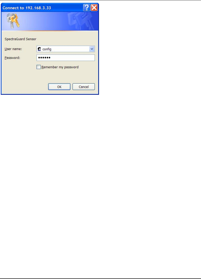
5.3.1 Step1: Log into the Web Interface
You have to log into the Web Interface to configure the SpectraGuard Sensor.
Manual Configuration of SpectraGuard Sensor
SpectraGuard Sensor Installation Guide
12
Figure 7 Login Screen
To log in, you have to perform the following steps:
1. Set your laptop as per the same subnet settings and a different IP address (ignore if
already done).
2. Type the correct IP address obtained from the DHCP Server in the Web Interface, for Web
configuration using the Ethernet cable. Type the address 192.168.1.245 in the Web
Interface, for Web (http) configuration using the crossover cable.
3. Log in using the user name ‘config’ and the password ‘config’, and click OK, as shown in
Figure 7 above.
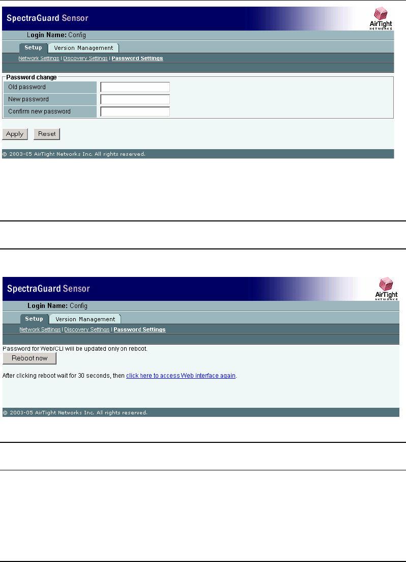
5.3.2 Step 2: Change Password Settings
For security reasons, you should immediately change the password after you log into the
SpectraGuard Sensor Console.
Manual Configuration of SpectraGuard Sensor
SpectraGuard Sensor Installation Guide
13
Figure 8 Password Settings Screen
The Password Settings Screen as shown in Figure 8 above appears by default and allows the user to
change the password. Enter the old password and the new password and click Apply.
Note: If you do not change the password the first time you log in, then the Password Settings Screen appears
every time you log into SpectraGuard Sensor. Once you change the password this screen does not reappear.
You will be asked to reboot SpectraGuard Sensor for the new password settings to take effect.
Figure 9 Reboot Screen
Note: A Reboot screen as shown in Figure 9 above appears once you have changed the password for the first
time or every time you change the password. Click ‘Reboot now’ to reboot SpectraGuard Sensor.
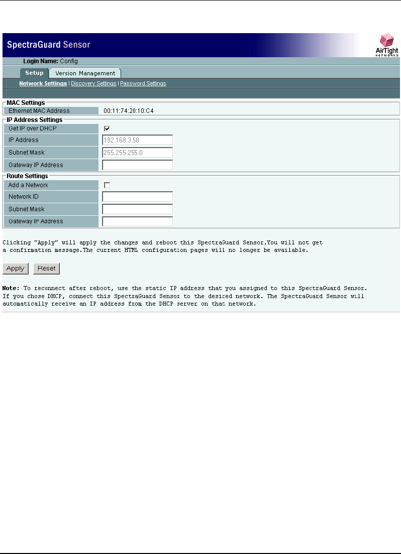
5.3.3 Step 3: Change Network Settings
Network Settings are used to set up the SpectraGuard Sensor IP address and Route Settings. These
Manual Configuration of SpectraGuard Sensor
SpectraGuard Sensor Installation Guide
14
settings are required so that the SpectraGuard Sensor can communicate with the SpectraGuard
Enterprise Server.
Figure 10 Network Settings Screen
There are three main sections under the Network Settings tab.
MAC Settings
IP Address Settings
Route Settings
MAC Settings
Ethernet MAC address shows the Media Access Control (MAC) address of the SpectraGuard
Sensor Ethernet Interface. This is a unique address assigned to every network interface. This field is
provided for information purposes only.
IP Address Settings
Change the fields mentioned below to modify the IP Address Settings:

Manual Configuration of SpectraGuard Sensor
SpectraGuard Sensor Installation Guide
15
Get IP over DHCP: This field is checked by default. This enables SpectraGuard Sensor to get an IP
address automatically from a DHCP Server. If this field is unchecked, you can set the IP address
manually.
IP Address: This field can be set only if the Get IP over DHCP field is unchecked. This field sets the
IP address of the SpectraGuard Sensor. The IP address should belong to the network segment on
which this SpectraGuard Sensor is to be connected.
Subnet Mask: This field can be set only if the Get IP over DHCP field is unchecked. This field
represents the mask of the network segment to which SpectraGuard Sensor will be connected.
Gateway IP Address: This field can be set only if the Get IP over DHCP field is unchecked. When
Ethernet traffic from the subnet is forwarded to another network, it is sent through the Gateway.
Enter the Gateway IP Address for the subnet on which this SpectraGuard Sensor is to be connected.
Note: You need to change the IP address only if you do not have a DHCP Server to assign an IP address
automatically.
Route Settings
Normally, you do not need to specify the route settings and these fields can be left blank. You
should specify the route settings only if the default gateway provided by DHCP is not the gateway
to the network segment where the SpectraGuard Enterprise Server is installed.
Add a Network: Checking this field allows you to add a network route to communicate with
SpectraGuard Enterprise Server.
Network ID: This field specifies the network segment ID where the SpectraGuard Enterprise Server
is connected.
Subnet Mask: This field represents the mask of the network segment where the SpectraGuard
Enterprise Server is connected.
Gateway IP Address: This field is the IP address of the gateway to the network segment where the
SpectraGuard Enterprise Server is connected.
Note: If the “Add a Network” checkbox is not checked, then the Network ID, Subnet Mask, and Gateway IP
Address are disabled.
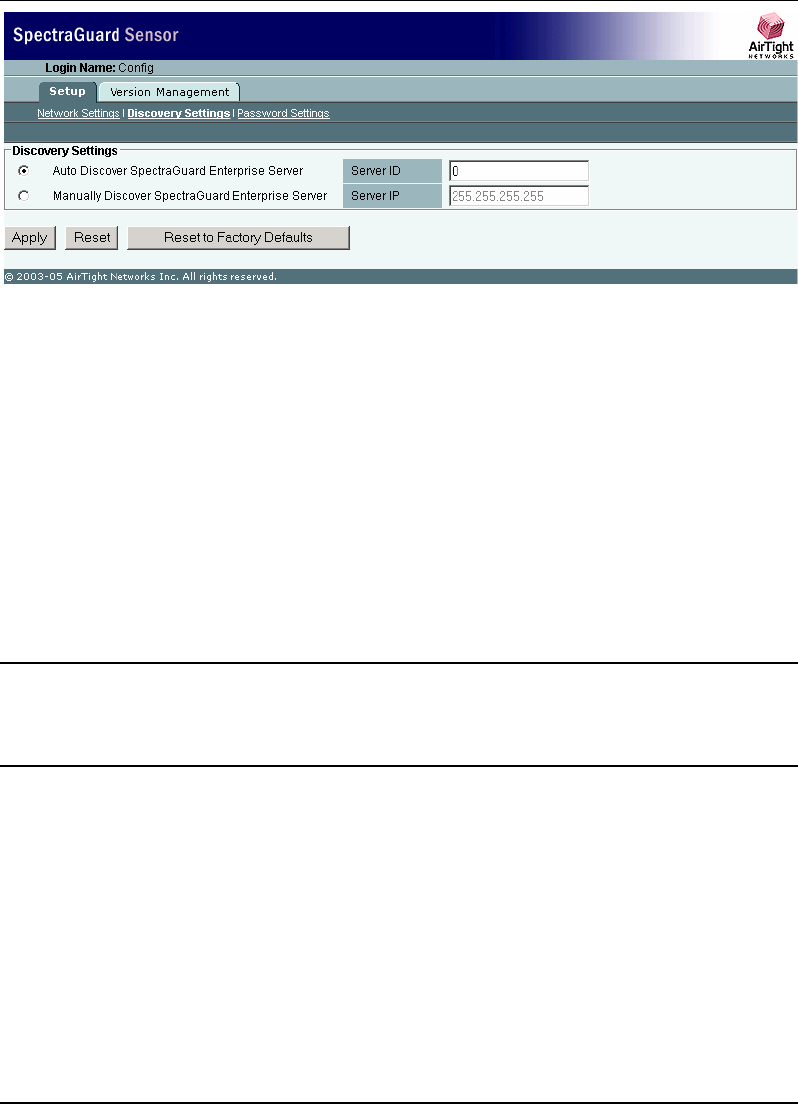
5.3.4 Step 4: Change Discovery Settings
Discovery Settings set up the discovery of the SpectraGuard Enterprise Server by the SpectraGuard
Sensor. These settings must be manually configured only if SpectraGuard Sensor is unable to locate
the SpectraGuard Enterprise Server.
Manual Configuration of SpectraGuard Sensor
SpectraGuard Sensor Installation Guide
16
Figure 11 Discovery Settings Screen
There are two main sections under Discovery Settings:
Auto Discover SpectraGuard Enterprise Server
Manually Discover SpectraGuard Enterprise Server
Auto Discover SpectraGuard Enterprise Server
You can set up the SpectraGuard Sensor to automatically discover and connect to the SpectraGuard
Enterprise Server. If you have multiple SpectraGuard Enterprise Servers on your network, each
SpectraGuard Enterprise Server will have a different Server ID. You must specify the Server ID of
the SpectraGuard Enterprise Server that this SpectraGuard Sensor should connect to.
Server ID: This is the SpectraGuard Enterprise Server ID to which the SpectraGuard Sensor should
connect. By default the Server ID is 0, which means that the connection will be attempted to any
SpectraGuard Enterprise Server that is available. This field needs to be changed only if there are
multiple SpectraGuard Enterprise Servers in the network.
Important! The “Server ID” setting in the SpectraGuard Sensor Console should be left as '0' if you want
SpectraGuard Sensor to auto detect the SpectraGuard Enterprise Server. In case you set the Server ID
manually, it must be set to the Server ID of the SpectraGuard Enterprise Server. If unsure, do not change
this field.
Manually Discover SpectraGuard Enterprise Server
You can set up the SpectraGuard Sensor to explicitly discover and connect to the SpectraGuard
Enterprise Server. You must specify the Ethernet IP address of the SpectraGuard Enterprise Server.
Server IP: This is the IP address of the SpectraGuard Enterprise Server to which the SpectraGuard
Sensor should connect. By default the Server IP address is 255.255.255.255.
Clicking Apply saves the changes.
Clicking Reset resets the parameters to their previous values without applying the changes.
Manual Configuration of SpectraGuard Sensor
SpectraGuard Sensor Installation Guide
17
Clicking Reset to Factory Defaults resets the configuration parameters to the factory default
settings. In this case, all the configuration settings, including the password settings will be restored
to factory defaults. Click this button, only when you want SpectraGuard Sensor to behave like a
brand new SpectraGuard Sensor.
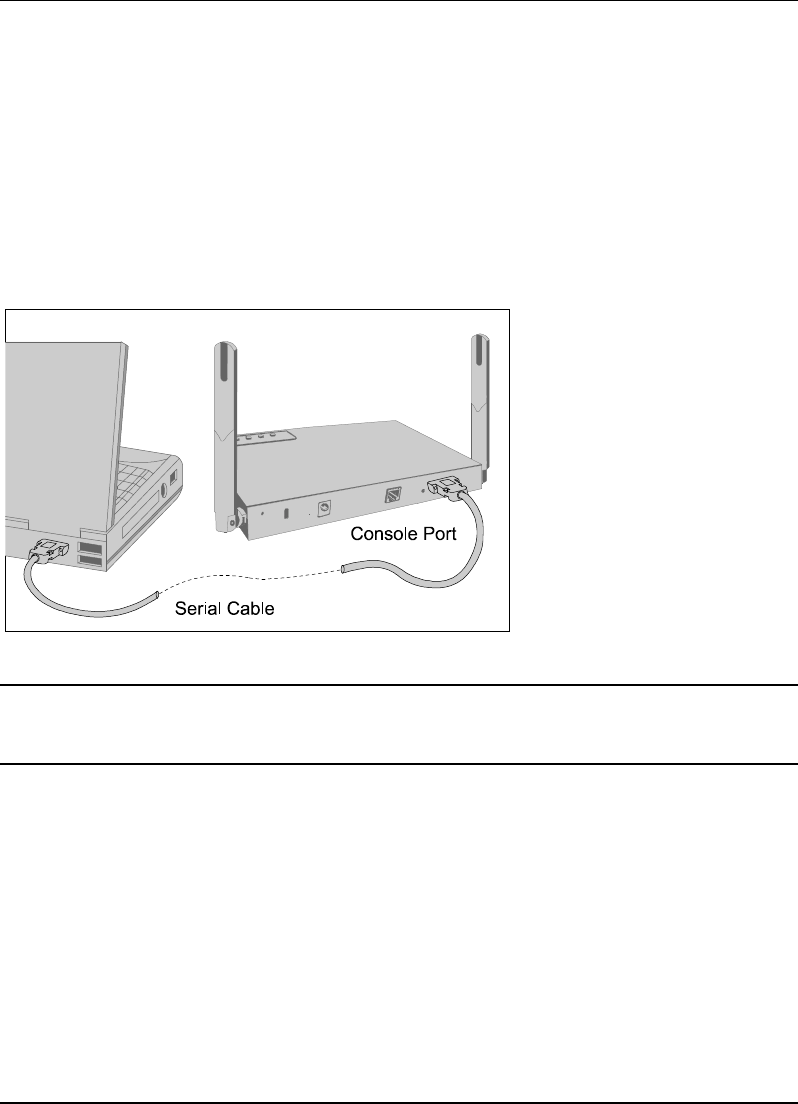
5.4 Configuring SpectraGuard Sensor though Command Line
Interface (CLI)
You can also configure the SpectraGuard Sensor using the Command Line Interface. To use the
Command Line Interface connect a Serial (RS-232) cable between your computer and the
SpectraGuard Sensor. The Command Line Interface supports a pre-defined set of commands used
for the SpectraGuard Sensor configuration.
Figure 12 Connecting to SpectraGuard Sensor using the Serial Cable
Note: It is recommended that you plug in the Serial Cable first and then start configuring the SpectraGuard
Sensor through the Command Line Interface. A Serial Cable is not provided in the SpectraGuard Sensor
package.
The following steps are used for configuring the SpectraGuard Sensor through the Command Line
Interface:
5.4.1 Step 1: Invoking the Command Line Interface
To start configuration of the SpectraGuard Sensor, you need to invoke the Command Line Interface
first. You need to follow the steps described below to invoke the Command Line Interface.
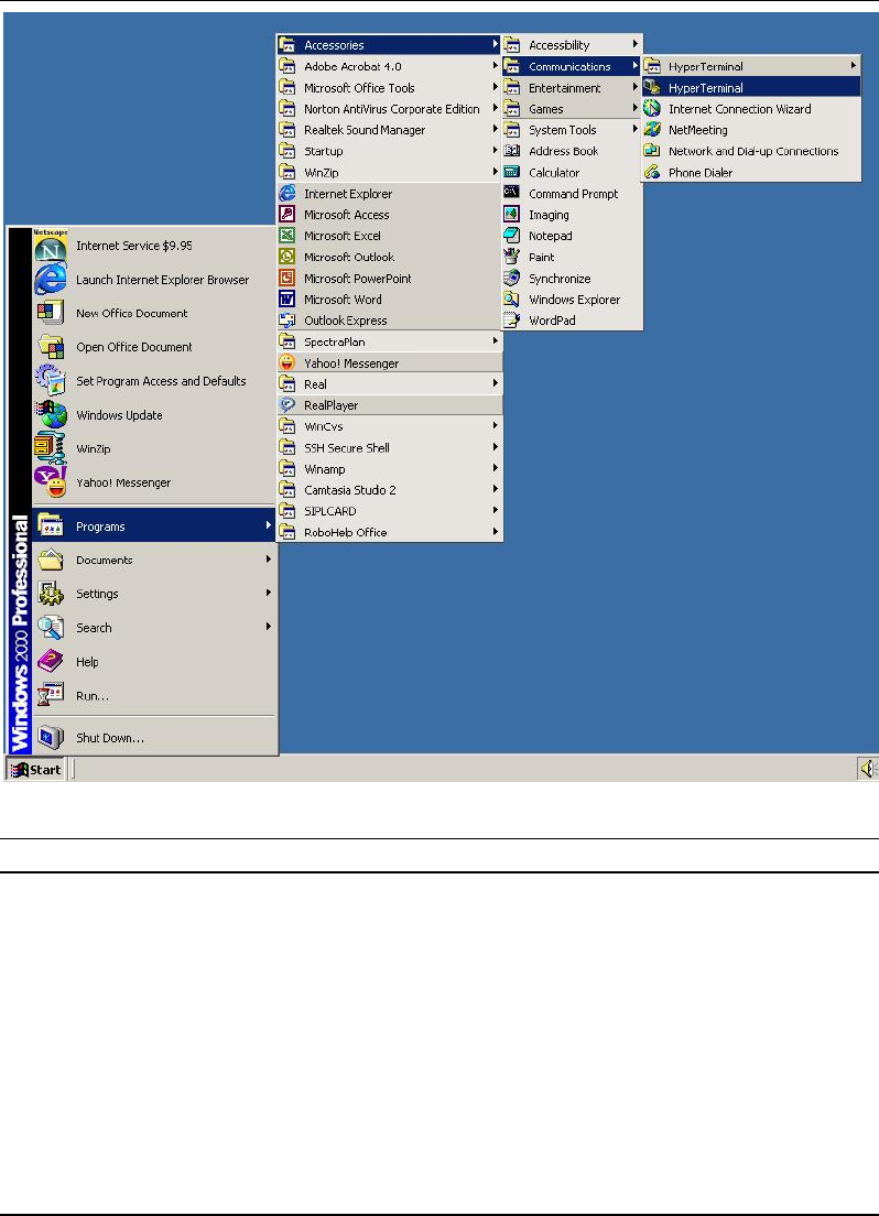
1. Opening HyperTerminal
To start HyperTerminal, click Start
Programs
Accessories
Communications
HyperTerminal as
shown in Figure 13 below.
Manual Configuration of SpectraGuard Sensor
SpectraGuard Sensor Installation Guide
18
Figure 13 Opening HyperTerminal
Note: If you are using a Linux laptop, you can use minicom to connect to the Command Line Interface (CLI).
2. Defining a New Connection
Once HyperTerminal opens, Figure 14 will appear by default. You have to name the new
connection, so that your connection is recognized. You can also select an icon to identify your new
connection.
Manual Configuration of SpectraGuard Sensor
SpectraGuard Sensor Installation Guide
19
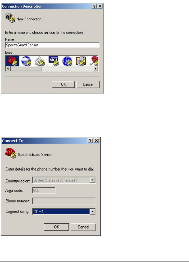
Figure 14 New HyperTerminal Connection
Type the desired name for the connection. For example, ‘SpectraGuard Sensor’ under the Name field
and click OK.
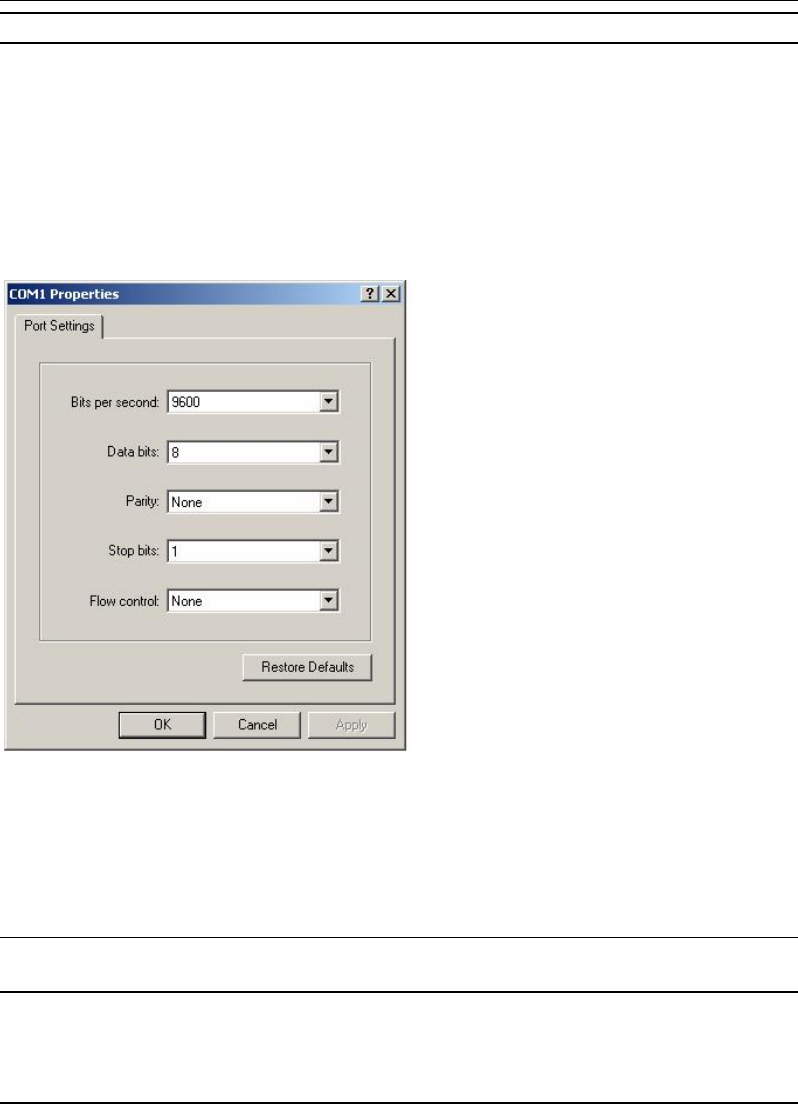
3. Adding Connection Details
Select the appropriate serial port from the Connect using drop-down list and click OK.
Figure 15 HyperTerminal Connection Details
Manual Configuration of SpectraGuard Sensor
SpectraGuard Sensor Installation Guide
20
Note: The name of the serial port will change as per the settings of your machine.
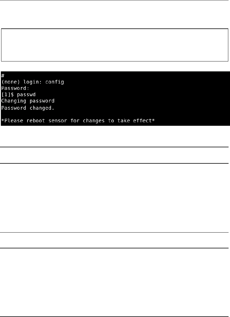
4. Editing Port Settings
Enter the following values under the COM Properties window to ensure proper transmission.
Bits per second: 9600
Data bits: 8
Parity: None
Stop bits: 1
Flow control: None
Figure 16 HyperTerminal Port Settings
After selecting these settings, click OK. The Command Line Interface is now ready.
5.4.2 Step 2: Log into the Command Line Interface and change password
You need to log into the Command Line Interface to start configuring the SpectraGuard Sensor.
The user name for login is config as shown in the Figure 17 below.
Recommended! For security reasons, it is recommended that you change the password immediately after
logging in to SpectraGuard Sensor.
Manual Configuration of SpectraGuard Sensor
SpectraGuard Sensor Installation Guide
21
The passwd command changes the password of the default user ‘config’. The default password is
‘config’.
Type the following commands (shown in bold) to change the Password Settings.
The following screen is an example from a live session.
Figure 17 Changing password using the passwd command
Note: A Reboot message appears, once you have changed the password for the first time. SpectraGuard
Sensor asks you to reboot every time you change the password.
5.4.3 Step 3: Change Network Settings
Network settings set up the SpectraGuard Sensor IP address and Route Settings. These settings are
required so that SpectraGuard Sensor can communicate with the SpectraGuard Enterprise Server.
Commands to change network settings
Type the following commands to change the network settings.
setdhcpip—This command allows you to get a DHCP assigned address for the Sensor.
setstaticip—This command allows you to assign a static IP address for the Sensor.
Note: If you set the DHCP IP settings using the setdhcpip command, you do not need to use the setstaticip
command.
The above commands are explained in detail below.
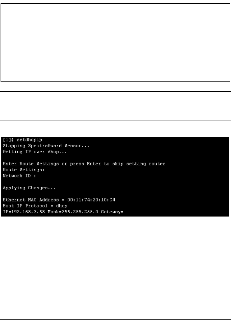
setdhcpip
This command configures the SpectraGuard Sensor to automatically get an IP address from the
DHCP Server.
Type the following command (shown in bold) to change the Network Settings:
$ login: config
Password: passwd
Changing password
Password changed.
*Please reboot sensor for changes to take effect*
Manual Configuration of SpectraGuard Sensor
SpectraGuard Sensor Installation Guide
22
Note: If IP address assignment via DHCP fails, the default values assigned are as follows:
IP address = 192.168.3.58
Net Mask = 255.255.255.0
If DHCP fails, the Sensor software doesn't begin execution.
The following screen is an example from a live session.
Figure 18 Changing network settings using the setdhcpip command
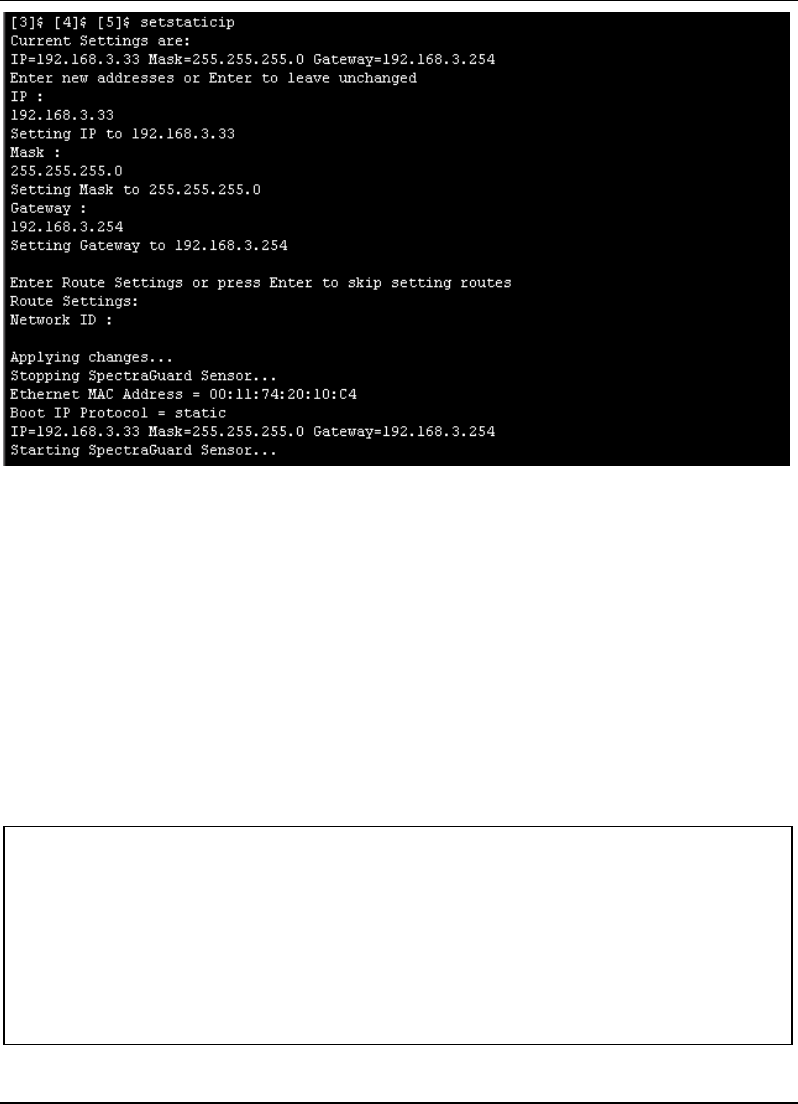
setstaticip
This command allows you to assign a static IP address for the Sensor and prompts you for the
following inputs:
A valid IP address—The IP address should be compatible with the network segment on which
this SpectraGuard Sensor is to be connected.
The corresponding subnet mask—This represents the mask of the network segment to which
the SpectraGuard Sensor will be connected.
$ setdhcpip
Stopping SpectraGuard Sensor...
Getting IP over dhcp...
Enter Route Settings or press Enter to skip settings routes
Route Settings:
Network ID:
Applying Changes...
Ethernet MAC Address = 00:11:74:20:10:C4
Boot IP Protocol = dhcp
IP=192.168.3.58 Mask=255.255.255.0 Gateway=

Manual Configuration of SpectraGuard Sensor
SpectraGuard Sensor Installation Guide
23
The default gateway—When Ethernet traffic from the subnet is forwarded to another network,
it is sent through the Gateway. Enter the Gateway IP Address for the subnet on which this
SpectraGuard Sensor is to be connected.
Route Settings—Normally, you do not need to specify the route settings. You should specify the
route settings only if the default gateway provided by the DHCP Server is not the gateway to the
network segment where SpectraGuard Enterprise Server is installed.
Network ID—This specifies the network segment ID, where the SpectraGuard Enterprise
Server is connected. (E.g.: 192.168.5.0)
Subnet Mask—This represents the mask of the network segment where the SpectraGuard
Enterprise Server is connected. (E.g.: 255.255.255.0)
Gateway—This is the IP address of the gateway to the network segment where the
SpectraGuard Enterprise Server is connected. (E.g.: 192.168.3.250)
Note: You can retain the default values for the above inputs by pressing Enter.
Type the following commands (shown in bold) to change the IP and Route Settings for the
SpectraGuard Sensor.
The following screen is an example from a live session.
$ setstaticip
Current Settings are:
IP=192.168.3.33 Mask=255.255.255.0 Gateway=192.168.3.254
Enter new addresses or Enter to leave unchanged
IP:
192.168.3.33
Setting IP to 192.168.3.33
Mask:
255.255.255.0
Setting Mask to 255.255.255.0
Gateway:
192.168.3.254
Setting Gateway to 192.168.3.254
Enter Route Settings or press Enter to skip setting routes
Route Settings:
Network ID:
Applying Changes...
Stopping SpectraGuard Sensor...
Ethernet MAC Address = 00:11:74:20:10: C4
Boot IP Protocol = static
IP=192.168.3.33 Mask=255.255.255.0 Gateway=192.168.3.254
Starting SpectraGuard Sensor...
Manual Configuration of SpectraGuard Sensor
SpectraGuard Sensor Installation Guide
24
Figure 19 Changing network settings using the setstaticip command
5.4.4 Step 4: Change Discovery Settings
Discovery Settings set up the discovery of the SpectraGuard Enterprise Server by the SpectraGuard
Sensor. These settings must be manually configured only if SpectraGuard Sensor is unable to locate
the SpectraGuard Enterprise Server.
Commands to change Discovery Settings
Type the following commands to change the Discovery Settings.
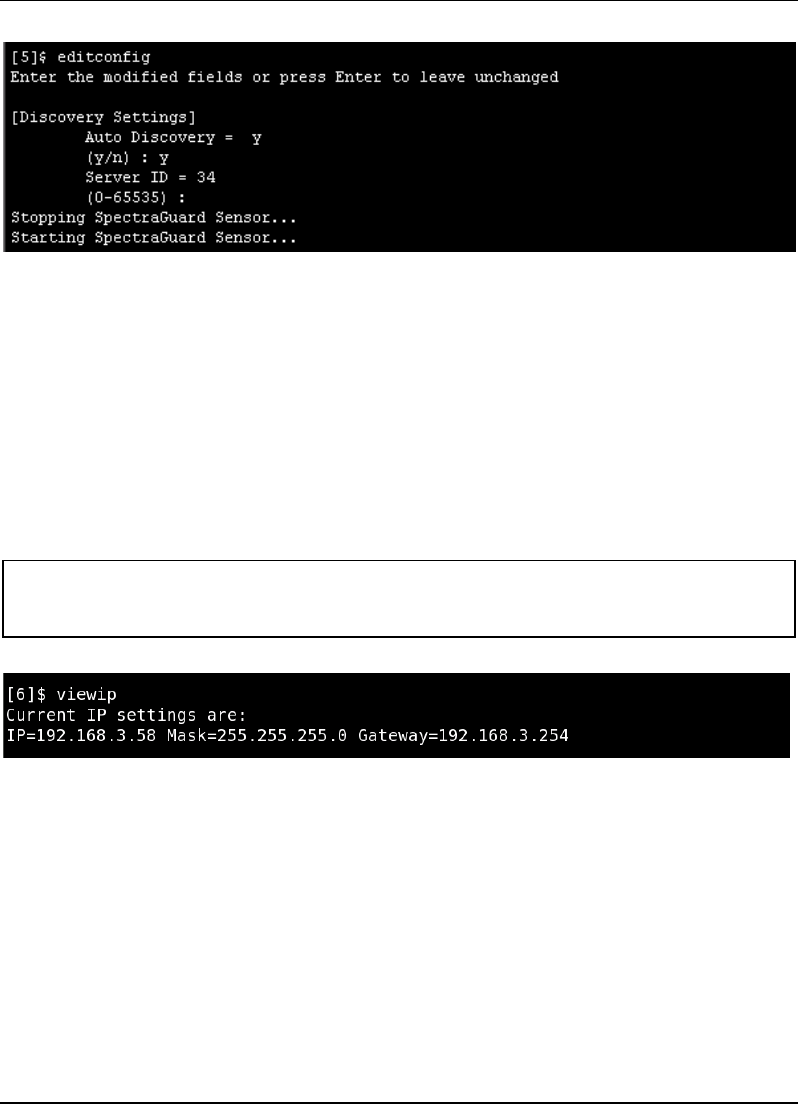
editconfig
This command allows the various SpectraGuard Sensor configuration parameters to be viewed and
changed. Pressing Enter leaves the previous values unchanged.
Type the commands (shown in bold) to change the Discovery Settings:
editconfig
Enter the modified fields or press Enter to leave unchanged
[Discovery Settings]
Auto Discovery = y
[y/n] : y
Server ID = 34
(0-65535) :
Stopping SpectraGuard Sensor...
Starting SpectraGuard Sensor...
Manual Configuration of SpectraGuard Sensor
SpectraGuard Sensor Installation Guide
25
The following screen is an example from a live session.
Figure 20 Changing Discovery Settings using the editconfig command
5.4.5 Other Commands
The following commands are optional and can be used to check the working of the SpectraGuard
Sensor. These commands are provided for information only and it is not necessary to use these
commands.
View the IP settings
viewip—This command displays the current IP address, subnet mask, and the Gateway IP Address
assigned to the Ethernet interface of the SpectraGuard Sensor. It also displays the route settings if
specified.
To view the IP settings, type the command (shown in bold) below in the CLI.
The following screen is an example from a live session.
Figure 21 Viewing network settings using the viewip command
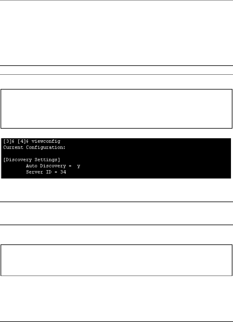
Modify the Configuration Settings
viewconfig—This command shows the current configuration of the Sensor, as shown in Figure 22
below. The various configuration parameters are as follows:
auto_discovery—This parameter signifies whether multicasting is enabled or not.
If Allowed="y"(Default) then multicast is enabled.
If Allowed="n" then multicast is disabled and the SpectraGuard Sensor connects to the
SpectraGuard Enterprise Server using unicast.
$ viewip
Current IP settings are:
IP=192.168.3.58 Mask=255.255.255.0 Gateway=192.168.3.254
Manual Configuration of SpectraGuard Sensor
SpectraGuard Sensor Installation Guide
26
server_ip—This parameter signifies the IP address of the SpectraGuard Enterprise Server
to which the SpectraGuard Sensor connects. This is valid and is displayed only if
auto_discovery="n", i.e., multicasting is disabled.
Default IP Address = 255.255.255.255
server_id—This parameter signifies the Server ID of the SpectraGuard Enterprise Server
to which the SpectraGuard Sensor connects. This is valid and will be displayed only if
auto_discovery="y", i.e., multicasting is enabled.
Default Server ID = 0
Note: Server ID “0” implies that connection will be attempted to any SpectraGuard Enterprise Server.
Type the following command (shown in bold) to view the current configuration settings:
The following screen is an example from a live session.
Figure 22 Viewing the current configuration settings using the viewconfig command
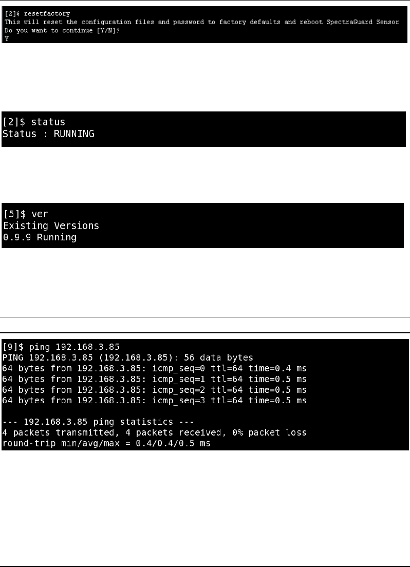
resetfactory—This command resets the Sensor configuration to the original factory settings.
Note: Please do not press the arrow keys or backspace keys in the Command Line Interface as they do not
work here. In case these keys are accidentally pressed, keep pressing Enter till the command finishes its
execution. Then execute the command once again.
Type the following commands (shown in bold) to reset to factory default settings:
The following screen is an example from a live session.
resetfactory
This will reset the configuration files and password to factory defaults
and reboot SpectraGuard Sensor
Do you want to continue [Y/N]?
Y
viewconfig
Current Configuration:
[Discovery Settings]
Auto Discovery = y
Server ID = 34
Manual Configuration of SpectraGuard Sensor
SpectraGuard Sensor Installation Guide
27
Figure 23 Resetting to factory default settings using the resetfactory command
Viewing the status of SpectraGuard Sensor
status—This command shows the current status of the Sensor. The two possible states are "Not
Running" or "Running".
Figure 24 status command
Viewing the status of the SpectraGuard Sensor software
ver—This command displays the version of the software running on the Sensor.
Figure 25 ver command
Getting the host information
ping—This command invokes the common "ping" program which checks whether a host is
reachable or not. It exits after sending and receiving four packets.
Important! Don't use Control + C, as it causes the shell to exit.
Figure 26 ping command
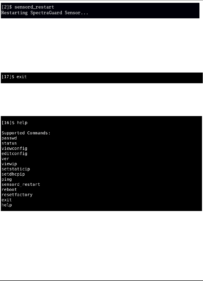
Restarting the Sensor
sensord_restart—This command restarts the Sensor i.e. causes the SpectraGuard Sensor software to
reinitialize. You do not need to reconfigure Sensor after the restart.
Manual Configuration of SpectraGuard Sensor
SpectraGuard Sensor Installation Guide
28
Figure 27 sensord_restart command
Rebooting the Sensor
reboot—This command causes the Sensor to physically reboot. You do not need to reconfigure
SpectraGuard Sensor after the reboot.
Exiting the shell
exit—This command causes the shell to exit and the login screen to appear.
Figure 28 exit command
Viewing the available commands
help—This command displays the list of available commands.
Figure 29 help command
To summarize, the Web (http) Interface is similar to the Command Line Interface in its capabilities.
You can choose either interface to configure SpectraGuard Sensor.

Troubleshooting
SpectraGuard Sensor Installation Guide
29
Chapter 6 Troubleshooting
Symptoms Diagnosis Solution
LED1: Yellow
LED2: Fast
Blinking Green
Not getting a DHCP
address.
The DHCP Server is down. Either bring up the DHCP
Server or set a static IP address via the Web (http) or
Command Line Interface.
LED1: Yellow
LED2: Slow
Blinking Green
Unable to connect to
the SpectraGuard
Enterprise Server.
Ensure that multicasting is enabled on your
router. If you don't want to do that, connect on
unicast by setting auto_discovery="n" and specify
the IP address of the SpectraGuard Enterprise
Server.
The other reason could be that SpectraGuard
Enterprise Server with the specified Server ID is
down or the Server ID is different from what is
configured.
Make sure you use only factory crimped
Ethernet cables with SpectraGuard Sensor or the
cable supplied in the package.
SpectraGuard Enterprise Server is possibly on a
different subnet that the default gateway doesn't
recognize. In such a case, you can specify an
alternate route on which the SpectraGuard
Enterprise Server resides via the Web (http) or
Command Line Interface. If this doesn't work,
then the SpectraGuard Enterprise Server with
the specified IP or ID is probably down or the
Server ID is different from what is configured.
LED1: Yellow
LED2: Green
The Ethernet cable is
loose. It is probably
disconnected from the
network.
Reconnect the Ethernet cable to the network.
LED1: Yellow
LED3: Green
An error on the 802.11
interface has occurred.
Contact support@airtightnetworks.net for more
details.
LED1: Yellow
LED4: Green
A fatal Software error
has occurred.
Contact support@airtightnetworks.net for more
details.