Arizona Max 5000Xl Users Manual 5000 User's
MAX-5000XL to the manual e33d5a56-f3f1-4418-a602-1d178b1571ee
2015-02-05
: Arizona Arizona-Max-5000Xl-Users-Manual-510774 arizona-max-5000xl-users-manual-510774 arizona pdf
Open the PDF directly: View PDF ![]() .
.
Page Count: 92

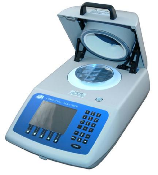
Arizona Instrument
Computrac
MAX 5000XL
MOISTURE ANALYZER
USER MANUAL
700-0113-A
Firmware Revision 3.0X
April 2008
Arizona Instrument LLC
1912 W 4th Street
Tempe, AZ 85281
(800) 528-7411
(602) 470-1414
Fax (480) 804-0656
http://www.azic.com
email:
azi@azic.com - General
intl@azic.com - International
support@azic.com - Customer Support
AZI Customer Service 800-528-7411 or 602-470-1414 Page 2 of 92
Computrac MAX 5000XL
PROPRIETARY RIGHTS NOTICE
The material in this manual contains valuable information developed by Arizona
Instrument LLC for use with the Computrac line of moisture analyzers. No part of this
manual can be reproduced or transmitted in any form or by any means, electronic,
mechanical, or otherwise. This includes photocopying and recording or in connection
with any information storage or retrieval system without the express written permission of
Arizona Instrument LLC.
ALL RIGHTS RESERVED
Copyright 2002-2008 Arizona Instrument LLC
AZI Customer Service 800-528-7411 or 602-470-1414 Page 3 of 92
TABLE OF CONTENTS
1. WARNINGS AND SAFETY INFORMATION ----------------------------------------------------------- 5
2. PACKING AND SHIPPING INSTRUCTIONS ---------------------------------------------------------- 7
3. INSTRUMENT DESCRIPTION ---------------------------------------------------------------------------- 9
3.1. Hardware ............................................................................................................................. 10
3.2. Oven .................................................................................................................................... 10
3.3. Inventory .............................................................................................................................. 11
4. INSTRUMENT SETUP ------------------------------------------------------------------------------------- 12
4.1. Interior of Test Chamber ................................................................................................... 13
4.2. AC Power Connection ....................................................................................................... 14
4.3. Contrast Adjustment .......................................................................................................... 16
4.4. Connecting a Printer .......................................................................................................... 16
4.5. Connecting a Computer .................................................................................................... 19
4.6. Connecting the External Filter Kit .................................................................................... 19
4.7. Calibrate the Balance - 50 gram weight ......................................................................... 20
4.8. Weight Test ......................................................................................................................... 22
5. MAIN MENU -------------------------------------------------------------------------------------------------- 23
5.1. Memory Starts Menu ......................................................................................................... 23
Editing Test Parameters ........................................................................................................ 24
Sample Name ................................................................................................................. 24
Temperatures .................................................................................................................. 25
Ending Criteria ................................................................................................................ 26
Sample Size Options ..................................................................................................... 29
Tare Options ................................................................................................................... 30
Result Display Options .................................................................................................. 32
Low Moisture CF ............................................................................................................ 32
Linked Test Options ....................................................................................................... 33
CUT Memory Start .................................................................................................................. 35
COPY Memory Start ............................................................................................................... 35
INSERT Memory Start ........................................................................................................... 35
PRINT Memory Start .............................................................................................................. 36
5.2. Stored Data Menu .............................................................................................................. 37
Delete Stored Data (Not available on 21 CFR, Part 11 compliant units) ........................ 37
Analyze Stored Data ............................................................................................................... 37
Select All Data ......................................................................................................................... 38
View Stored Data .................................................................................................................... 39
Print Stored Data..................................................................................................................... 39
5.3. Calibration Menu ................................................................................................................ 40
Balance Calibration ................................................................................................................. 40
Calibrate Balance ........................................................................................................... 40
View Calibration Report ................................................................................................. 41
Calibration Reminder Setup .......................................................................................... 41
High Temperature Lift Calibration......................................................................................... 42
Temperature Calibration ........................................................................................................ 43
Verification Setup ........................................................................................................... 43
Calibration Module Setup .............................................................................................. 43
Perform Calibration ........................................................................................................ 44
Perform Verification........................................................................................................ 44
View Cal Report .............................................................................................................. 45
Calibration Reminder Setup .......................................................................................... 46
Temperature Calibration Instructions .......................................................................... 47
Oven Cleaning ......................................................................................................................... 49
Cleaning Reminder Setup ............................................................................................. 49
5.4. Setup Menu ......................................................................................................................... 50
Printer Setup ............................................................................................................................ 50
Report Setup ............................................................................................................................ 51
Report Control Options .................................................................................................. 51
AZI Customer Service 800-528-7411 or 602-470-1414 Page 4 of 92
Report Items to Print ...................................................................................................... 52
Add/Edit Company Name .............................................................................................. 52
Date/Time Setup ..................................................................................................................... 52
Data Format Setup ................................................................................................................. 53
EC Display ....................................................................................................................... 53
Lot Number ...................................................................................................................... 53
Access Key Setup ................................................................................................................... 54
Master Key ...................................................................................................................... 54
Calibration Key ............................................................................................................... 54
Ethernet Setup ........................................................................................................................ 54
NAME and PASSWORD ............................................................................................... 55
OBTAIN IP ADDRESS .................................................................................................. 55
MAC ADDRESS ............................................................................................................. 55
STATUS ........................................................................................................................... 55
Special Features ..................................................................................................................... 56
5.5. Sample Foils ....................................................................................................................... 56
Enter Foils ................................................................................................................................ 56
5.6. Parameter Expert (Optional Feature) .............................................................................. 58
Develop From Scratch ........................................................................................................... 58
Optimize Temp/Speed/Repeatability ................................................................................... 62
6. SAMPLE PREPARATION, TESTING AND ANALYSIS ------------------------------------------ 64
6.1. Balance Temperature Stability ......................................................................................... 64
6.2. Preparing Granular and Powdery Samples ................................................................... 65
6.3. Preparing and Testing Liquid Samples ........................................................................... 65
6.4. Selecting the Optimum Sample Size .............................................................................. 66
7. PERFORMANCE ENHANCEMENT -------------------------------------------------------------------- 66
7.1. Introduction ......................................................................................................................... 66
7.2. Determining Proper Test Temperature ........................................................................... 68
7.3. Selection of Ending Criteria .............................................................................................. 69
8. PERFORMANCE VERIFICATION ---------------------------------------------------------------------- 70
8.1. The Weight Test ................................................................................................................. 70
8.2. The Precision Weight Test ............................................................................................... 71
8.3. Sodium Tartrate Test ......................................................................................................... 72
8.4. Precision Sodium Tartrate Test ....................................................................................... 73
8.5. Retained Samples .............................................................................................................. 74
9. WEB SERVER ----------------------------------------------------------------------------------------------- 75
9.1. Calibration Report .............................................................................................................. 75
9.2. LCD View ............................................................................................................................ 76
9.3. Memory Starts .................................................................................................................... 76
9.4. Test Results ........................................................................................................................ 77
10. ROUTINE MAINTENANCE ------------------------------------------------------------------------------- 78
10.1. Chamber Interior ................................................................................................................ 78
10.2. Shroud Gasket ................................................................................................................... 79
10.3. Insulator Seal ...................................................................................................................... 79
10.4. Oven Chamber Cleaning .................................................................................................. 80
10.5. Oven Vent Cleaning .......................................................................................................... 81
10.6. External Filter Cleaning ..................................................................................................... 81
10.7. Sample Pan Support ......................................................................................................... 82
10.8. Lithium Battery Replacement ........................................................................................... 82
11. TROUBLE DIAGNOSIS ----------------------------------------------------------------------------------- 83
12. ACCESSORIES & MAINTENANCE PARTS -------------------------------------------------------- 86
13. MAX 5000XL SPECIFICATIONS ----------------------------------------------------------------------- 87
14. CHANGES ----------------------------------------------------------------------------------------------------- 90
15. WARRANTY -------------------------------------------------------------------------------------------------- 91

AZI Customer Service 800-528-7411 or 602-470-1414 Page 5 of 92
1. WARNINGS AND SAFETY INFORMATION
The MAX 5000XL moisture analyzer complies with
the Underwriter Laboratories Inc. standards and
European Council Directives, for Electrical
Equipment for Laboratory Use, electromagnetic
compatibility, and the stipulated safety
requirements. However, improper use or handling
of the instrument can result in damage to the
equipment and/or injury to personnel.
The MAX 5000XL is Equipment Class I, Pollution
Degree 2, and Installation Category II.
Read these operating instructions thoroughly before
using your moisture analyzer to prevent damage to
the equipment. Keep these instructions in a safe
place.
The following instructions will help to ensure safe
and trouble-free operation of your MAX 5000XL.
Use the analyzer only for performing
moisture/solids/ashing analysis of samples.
Any improper use of the analyzer can endanger
persons and may result in damage to the
analyzer or other material assets.
Place analyzer in an appropriate fume hood for
ashing and/or burning a sample.
When ashing and/or burning a sample, use the
ash rate to slow ignition and prevent flaming. If
the sample flames, it will damage the heater
and produce poor test results.
Do not use this analyzer in a hazardous
area/location; operate it only under the ambient
conditions specified in these instructions.
Although the analyzer is simple to operate and
is very user friendly, it should only be operated
by qualified persons who are familiar with the
properties of the sample being analyzed.
Ensure, before getting started, that the voltage
rating printed on the manufacturer's label is
identical to your local line voltage (see the
section on AC Power Connection beginning on
page 14).
The MAX 5000XL is provided with a power cord
that has a protective grounding conductor. Do
not operate the unit without the supplied
three-wire power cord or an identical
recognized equivalent that meets all applicable
standards.
AZI does not recommend the use of an
extension cord. However, if one must be used,
use an extension cord that meets all applicable
standards and has a protective grounding
conductor.
Do not remove the protective grounding wire
from the power supply circuit
With the power switch off, power is still applied
to the power entry module. Remove the power
cord from the MAX 5000XL to ensure complete
power removal from the instrument.
Position the power cable so that it cannot touch
any hot areas of the analyzer.
Use only AZI supplied accessories and options
with the MAX 5000XL or check with AZI before
using any third party accessories, such as
printers and analytical balances, to verify
compatibility.
If there is visible damage to the MAX 5000XL or
its power cord, unplug and isolate the unit first
and then call Customer Service at
800-528-7411 or 602-470-1414.
Do not open the housing of the MAX 5000XL.
There are no user serviceable parts or
adjustments inside the unit. Any maintenance
inside the unit is to be performed by
factory-trained technicians only. Any
unauthorized inspection and/or maintenance of
the MAX 5000XL will make the warranty null
and void.
Lithium Coin Cell Battery
The MAX 5000XL contains a lithium battery to
keep power on the clock when the unit is turned
off.
CAUTION – The battery may explode if
mistreated. Do not recharge, disassemble or
dispose of in fire.
Prevent excess heat build-up around the
analyzer
When setting up the analyzer, leave enough
space to prevent heat from building up and to
keep your analyzer from overheating. Leave 20
cm (about 8 in.) around the analyzer and 1 m
(about 3 ft.) above the unit.
Do not put any flammable substances on, under
or near the analyzer, because the area around
the unit will heat up, especially during the
self-cleaning cycle.
Use extreme care when removing the sample
from the chamber. Although the ceramic heating
chamber cools rapidly, the sample itself, the
sample pan, and the heating element can still be
extremely hot.

AZI Customer Service 800-528-7411 or 602-470-1414 Page 6 of 92
HAZARDS FOR PERSONS OR EQUIPMENT
POSED BY USING SPECIFIC SAMPLES:
Flammables; explosives; substances that contain
flammables, explosives, solvents; and/or
substances that release flammable or explosive
gases or vapors during the drying process.
The user shall be liable and responsible for any
damage that arises in connection with the MAX
5000XL and potentially harmful substances.
Substances containing toxic, caustic, or
corrosive substances may be analyzed with the
unit in an appropriate fume hood only. The
fume hood must keep the work area below the
lower toxic limit established by appropriate
standards.
Substances that release caustic vapors such as
acids should be analyzed in the smallest
sample size possible to still achieve satisfactory
results. If vapors condense on the MAX
5000XL housing parts, stop the testing, wipe
the surface clean with a suitable neutralizer and
place the unit in a fume hood capable of
removing the vapors.
The user has the responsibility for carrying out
appropriate decontamination if hazardous
material is spilled on or inside the MAX 5000XL.
CLEANING the MAX 5000XL
Clean the MAX 5000XL according to the
cleaning instructions only. Use of strong
detergents and “oven cleaners” will damage the
case and heater housing of the MAX 5000XL.
Before using any cleaning or decontamination
method except those recommended by Arizona
Instrument, check with AZI Customer Service at
800-528-7411 or 602-470-1414, to ensure that
the proposed method will not damage the
equipment.
The outside housing of the MAX 5000XL should
be cleaned with a mild household detergent
such as Formula 409 and a soft, lint-free cloth.
Paper towels should never be used, as they
will scratch the instrument’s finish and the clear
lens over the display. Since the MAX 5000XL
has a built-in cleaning mode of operation, no
cleaning product should be necessary for the
oven. If the 550O C self-cleaning cycle does not
clean the oven, call AZI Customer Service at
800-528-7411 or 602-470-1414 for
recommendations.
Every precaution has been taken to prevent
contaminants from entering the unit. However,
if liquids or powders do enter the case, call AZI
Customer Service at 800-528-7411 or
602-470-1414 for recommendations.
The user shall be liable and responsible for any
damage that arises in connection with this analyzer.
ENVIRONMENTAL CONDITIONS
Storage and Shipping
Temperature should be between 0OC to +35 OC
(+32OF to +95OF).
Relative Humidity should be between 10% and
80%.
OPERATIONAL CONDITIONS – INDOOR USE.
Optimum results will be achieved when the unit is
set on a smooth, level, non-vibrating surface in a
non-condensing, non-explosive environment of
0-35º C at 50% relative humidity and 0-31º C at 80%
relative humidity.
Do not expose the moisture analyzer unnecessarily
to extreme temperatures, moisture, shocks, blows
or vibration.
UNPACKING THE MOISTURE ANALYZER
After unpacking the moisture analyzer, check it
immediately for any visible damage resulting from
rough handling during shipment.
Save the box and all parts of the packaging to use
when returning your moisture analyzer for
calibration. Only the original packaging provides
the AZI-recommended protection for shipment.
Before packing your moisture analyzer for
shipment, unplug all connected cables and remove
the pan support to prevent damage during transit.
WARNING SYMBOLS
- Protective Ground
Identifies the connection on the chassis
and power inlet module for connection of
the safety ground (green/yellow) wire.
- Warning
Information or procedure that must be
observed.
- Electrical Shock Hazard.
Observe all steps of the procedure to
prevent electrical shock.
- Warning, Hot surface or area of
possible severe burns.
Use listed precautions when opening the
oven lid and handling samples to prevent
injury.
AZI Customer Service 800-528-7411 or 602-470-1414 Page 7 of 92
2. PACKING AND SHIPPING INSTRUCTIONS
IMPORTANT
Movement, handling, and packaging of the instrument must be done with
EXTREME CARE to avoid permanent, expensive internal damage. The MAX
5000XL uses a delicate and very sensitive electronic force balance to measure
small weights and weight losses. The balance is capable of measuring weight to
a resolution of 0.1 milligram. Careful handling is necessary to prevent damage to
the balance. With proper care, the instrument will provide years of dependable
service.
UNPACKING
Unpack the instrument carefully and set it down gently. Select a place
where it will be safe from bumping, jarring, excessive air currents, and
vibration.
Retain all packaging materials for any future shipment of the
instrument. If the instrument is returned to AZI for any reason, place it
in the original packaging materials. Only the original packaging
materials have been tested and proven effective during shipment.
REPACKAGING FOR SHIPMENT
Call AZI Customer Service at 800-528-7411 or 602-470-1414 for Return Material
Authorization (RMA) information prior to returning a unit.
Remove the Pan Support from the instrument and pack in a separate box before
shipment.
For all shipments, boxes and packing materials are available from AZI.
Pack the MAX 5000XL in a Computrac MAX 5000XL shipping container only.
AZI WILL NOT BE RESPONSIBLE FOR SHIPPING DAMAGE.
IF YOU RETURN THE INSTRUMENT IMPROPERLY PACKAGED OR SHIPPED, YOU
SHOULD INSURE IT FOR FULL VALUE.
AZI Customer Service 800-528-7411 or 602-470-1414 Page 8 of 92
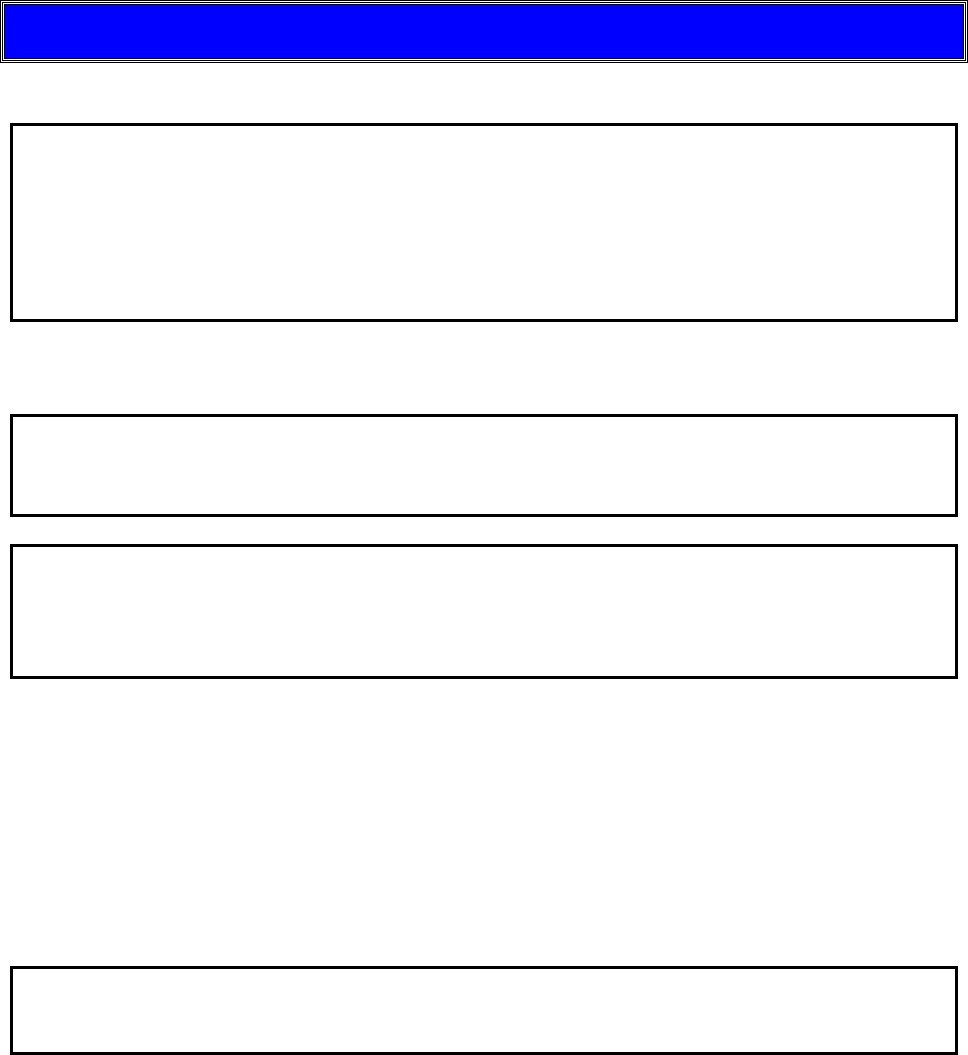
Please save the shipping box and all
packaging materials for future use.
REMOVE THE PAN SUPPORT and Pack
separately
BOX FOR PAN SUPPORT

AZI Customer Service 800-528-7411 or 602-470-1414 Page 9 of 92
3. INSTRUMENT DESCRIPTION
The Computrac MAX 5000XL is a high performance programmable loss-on-drying
analyzer.
Typical
Repeatability:
Moisture Level (%)
>10% <5% Relative Standard Deviation
>0.1% <0.1 Standard Deviation
Ash (%)
>10% ≤5% Relative Standard Deviation
>0.5% ≤0.1 Standard Deviation
Periodic balance and temperature calibration maintains accuracy.
Test temperatures from 25º C to 600º C set at increments of one degree.
Programming is through the front panel keyboard and menu system.
Programming features can be placed under access code control, preventing
unwanted changes to operating parameters.
Stored test parameters for 250 different materials to include 244 user
programmable sets and 6 factory set test parameters.
Test data can be:
Stored in the instrument, (the last 1,000 tests and 100 graphs)
Sent directly to a personal computer, and
Printed on many graphics-capable printers with a printed graphical
representation of the drying process.
The instrument can calculate mean, standard deviation and relative standard
deviation for up to 1,000 stored test results.
On 21 CFR, Part 11 compliant instruments, the Delete Stored Data function is
disabled throughout the system.
AZI Customer Service 800-528-7411 or 602-470-1414 Page 10 of 92
3.1. Hardware
The MAX 5000XL consists of:
A ceramic convection air oven
A precision balance weighing mechanism with a resolution of 0.0001 gram and a
full scale range of 100 grams
A backlit, color graphic liquid crystal display
A microprocessor that controls the test process, data handling, communications,
and performs all necessary calculations, and
Connectors on the back panel for an Ethernet connection, parallel printer, and
serial communications devices (Other connections are provided that will be
implemented in later revisions to the instrument.)
The MAX 5000XL is designed to remain powered up at all times.
The balance requires a lengthy warm up period. The first test of the day can be made
sooner and with more accuracy if the unit remains powered over night. When not in use,
select a test with start temperature of 25º C and keep the lid down. The oven will remain
cool and the Liquid Crystal Display (LCD) backlight will turn off after a period of inactivity
to conserve energy. Press any key to restore illumination to the LCD.
If the test process is interrupted by outside interference such as static discharge, surges
or drops in line voltage, or otherwise freezes its operation and/or display, reset the
instrument by recycling power. By turning the instrument off and back on, the instrument
should return to normal operation. If the instrument does not return to normal operation,
contact AZI Customer Service at 800-528-7411, 602-470-1414, or by e-mail at
support@azic.com.
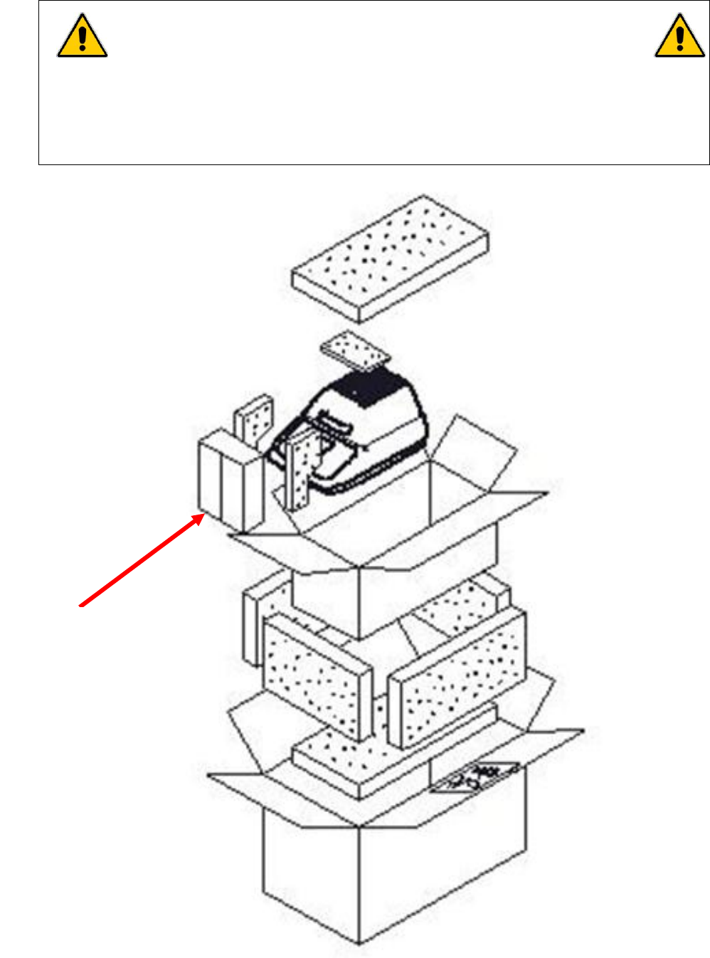
3.2. Oven
The ceramic sample oven maintains accurate temperature
control to prevent sample degradation as it removes volatile
components as quickly as possible. A Resistance Temperature
Device (RTD) mounted near the heater measures oven
temperature. Temperature is held within one or two degrees of
the set value (depending on the set value) after equilibrium is
reached. The oven usually reaches test temperature in 90 to 180
seconds, depending on the difference between the starting and
setpoint temperatures. The oven is automatically turned off
when the test is completed.
Due to the nature of the oven lining, the oven is cool almost
immediately after opening the lid. The sample will remain hot much
longer than the oven itself so caution is required when removing
used sample pans from the oven.
AZI Customer Service 800-528-7411 or 602-470-1414 Page 11 of 92
3.3. Inventory
Carefully unpack the instrument and locate the following items:
Part Name
AZI Part
Number
MAX 5000XL
MAX 5000XL
Accessory Kit
Y990-0158
Line Cord, 110 VAC
200-0002
or Line Cord, 220 VAC (UK)
200-0003
or Line Cord, 220 VAC (Europe)
200-0008
Test Weights: 3grams
5 grams
50 grams
690-0003
690-0004
690-0025
Tweezers
690-0012
Sample Pans, Waffle: 100 ea.
990-0008
Sample Pans, Heavy: 5 ea.
990-0196
Optional Accessories*
Printer Kit
Y990-0098
Serial Cable - null modem for
computer interface
6000-1044
Temperature Calibration Kit,
110V
Y990-0193
Temperature Calibration Kit,
220V
Y990-0224
Sample Pans, Flat: 100 ea.
990-0010
Filter Paper
990-0003
External Filter Kit
Y990-0210
* See page 86 for a complete listing of available accessories
AZI Customer Service 800-528-7411 or 602-470-1414 Page 12 of 92
4. INSTRUMENT SETUP
Contact Arizona Instrument Customer Service at 800-528-7411 or 602-470-1414 or by
e-mail at support@azic.com if you have any questions about the following instructions.
The MAX 5000XL is designed to provide reliable results under normal ambient conditions
in the laboratory and on the production floor. Compliance with the following guidelines will
help ensure optimum accuracy in minimum time.
Set up the MAX 5000XL on a stable, even surface that is not exposed to vibrations.
Select a location for the instrument that is:
Firm and level,
Free from vibration that will affect the balance measurements,
Close to an isolated power outlet that will provide dedicated electrical power,
and
Away from the direct flow of a fan or heating/air-conditioning outlet that might
produce force on the balance
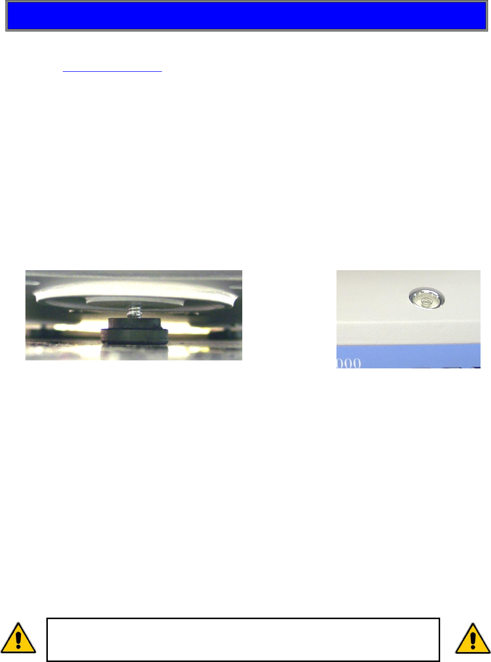
Adjust the feet under the instrument to center the bubble in the level located under
the lid.
An operational clearance of at least 20 cm (8 inches) above the instrument is
recommended.
Keep all cables as short as possible, less than 2 meters (6 feet) in length if
possible.
Avoid placing the analyzer in close proximity to a heater or otherwise exposing it to
heat or direct sunlight.
Avoid exposing the analyzer to extreme temperature fluctuations.
Protect the analyzer from drafts that come from opening windows, doors and air
conditioning systems.
Keep the analyzer protected from dust and liquids as much as possible.
Protect the analyzer from caustic vapors.
Do not expose the analyzer to saturated humidity environments.
Moisture in the air can condense on the surfaces of a cold analyzer whenever it is
brought into a substantially warmer place. If you move the MAX 5000XL to a
warmer area, make sure to condition it at room temperature, disconnected from
AC power, for at least 2 hours, or until moisture condensation no longer occurs.
For those familiar with moisture analysis instruments, the MAX 5000XL
should be simple to operate. However, please read all of the sections in
this manual before attempting your first analysis.
AZI Customer Service 800-528-7411 or 602-470-1414 Page 13 of 92
4.1. Interior of Test Chamber
Remove the sample pan support from its separate box and packing foam.
Save the box and foam so that the support can be packaged when the instrument
is returned to the factory for annual calibration.
NOTE: Shipment of the instrument with the pan support in place will
damage the ceramic oven and the balance. Damage caused by
improper shipment is not covered by the warranty.
Open the lid of the MAX 5000XL by lifting the
handle just above the display.
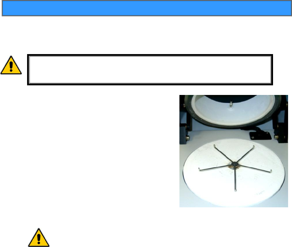
Install the pan support gently but firmly into the
instrument. The stem of the pan support fits
snugly into the balance.
Check the clearance between the pan support
arms and the heat shield by observing the
space between the arms and the heat shield.
The clearance should be between 1.5mm to
4.75mm, [1/16” to 3/16”] and equal for all five
arms of the pan support. If the clearance is
considerably different for one arm or the pan
support appears to be crooked, call AZI
Customer Service at 800-528-7411 or
602-470-1414.
CAUTION - Avoid excess pressure from the top or sides of the pan
support that can damage the force balance. Only install or remove
the pan support when the instrument is powered OFF.
AZI Customer Service 800-528-7411 or 602-470-1414 Page 14 of 92
4.2. AC Power Connection
The MAX 5000XL can be used with a 100-130 VAC or a 220-240 VAC input power
source. Check the setting on the fuse holder, located at the rear of the instrument, and
make sure it is set for the correct voltage for your environment.
Ensure the AC power receptacle is set for the correct voltage for
your environment. For best results, AZI recommends that the
instrument is provided with its own DEDICATED electrical power
outlet. Do not put it on a circuit with motors, blenders, heaters,
coolers, grinders, or other high current electrical devices.
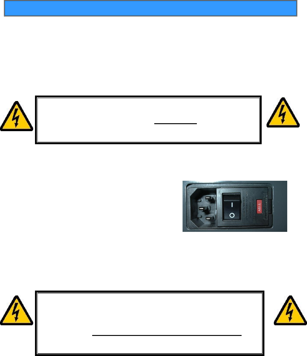
To ensure the entry module is set for the correct voltage:
Locate the fuse holder on the rear of the instrument.
Pull the fuse access cover open and down.
Pry the fuse holder from the power entry
module.
Ensure only 8 amp timed fuses are installed
for 100-130 VAC operation or only 4 amp
timed fuses are installed for 220-240 VAC
operation.
Reinstall the fuse holder into the power entry module with the correct voltage
showing, as in the picture above which shows 115V configuration.
Ensure the power switch, located next to the fuse holder, is in the OFF position.
Remove the power cord from the packing material and insert the rectangular end
into the power receptacle, located on the other side of the fuse holder.
The power source outlet used by the MAX 5000XL MUST BE
GROUNDED. (If you are not sure if the socket is grounded, check
with your plant electrician before proceeding). The MAX 5000XL
will appear to function correctly even if the socket is not
grounded, but there is a danger of possible electrocution! If
grounded outlets are not available, consider using a ground
fault interrupter to protect personnel against electrical shock.
Power Requirements:
100-130 VAC, 50/60 Hz @ 8 Amps – fuse is F8A T250V
220-240 VAC, 50/60 Hz @ 4 Amps – fuse is F4A T250V
Fused on/off switch is part of an EMI power entry module
AZI Customer Service 800-528-7411 or 602-470-1414 Page 15 of 92
All accessory equipment, printer, computer, etc., should be connected before applying
power to the instrument. See the following sections, 4.4 and 4.5, to connect a printer
and/or computer.
Plug the line cord into a dedicated electrical power outlet. Line noise on the power lines
may affect accuracy. A dedicated AC power line or an isolation transformer for the MAX
5000XL may be beneficial in eliminating this noise.
Turn the instrument on by pressing the switch on the back of the analyzer next to the
power receptacle.
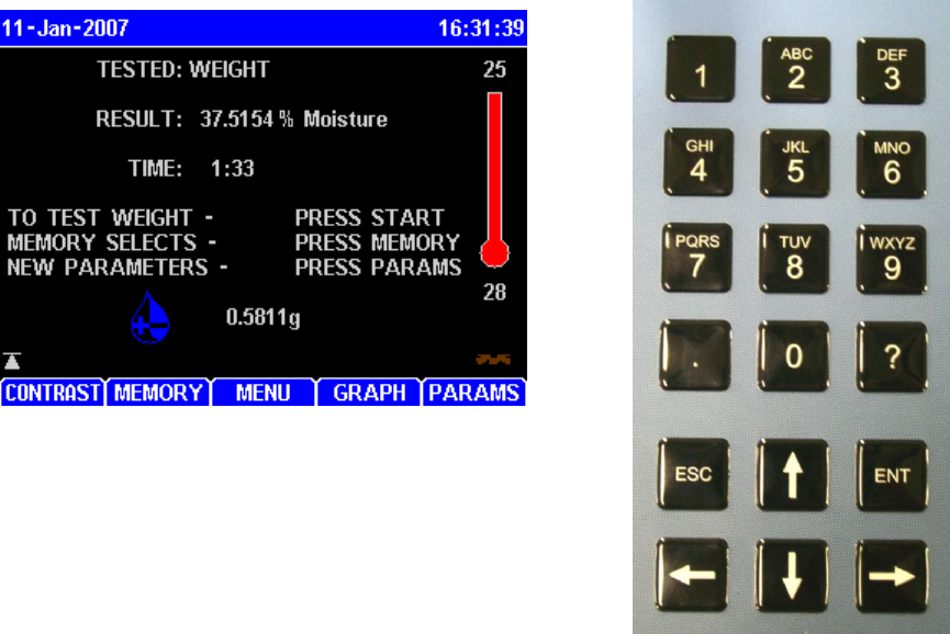
After displaying the opening screen for about five seconds, the main test screen shown
below will appear. (It may be necessary to press ESC to clear any calibration reminders).
The keypad functions are:
The Left and Right Arrow Keys move the cursor
one space left or right in edit mode or to the next
field on some input screens. They move the
highlight bar one page at a time when selecting
stored memory starts or stored data test results.
(Stored data is not available on all instruments)
The Up and Down Arrow Keys move the cursor
up and down through lists in edit mode. They move the highlight bar one line
at a time when selecting stored memory starts, stored data, or lines on input
screens.
The Alphanumeric Keys toggle through the listed characters plus a blank
space.
The ENT Key selects most functions. Other functions are selected with keys
below the screen. As operating modes change, the function of the keys below
the display change. The function performed by the key is displayed and
changed with operating mode changes.
The ESC Key is used to exit menus. Many functions that are Yes/No or On/Off
type selections will be saved when the ESC Key is depressed. If the field is
editable with numbers or letters, the ESC key allows an abort without changing
contents
AZI Customer Service 800-528-7411 or 602-470-1414 Page 16 of 92
After power-up, the balance temperature will be stabilized for high temperature
testing, which may take up to 2 hours. Wait for the balance temperature stability
icon on the main screen to change from unstable to stable before performing
the balance calibration or low moisture/solids/ash testing (<1%). See section 6.1
Balance Temperature Stability on page 64 for more information.
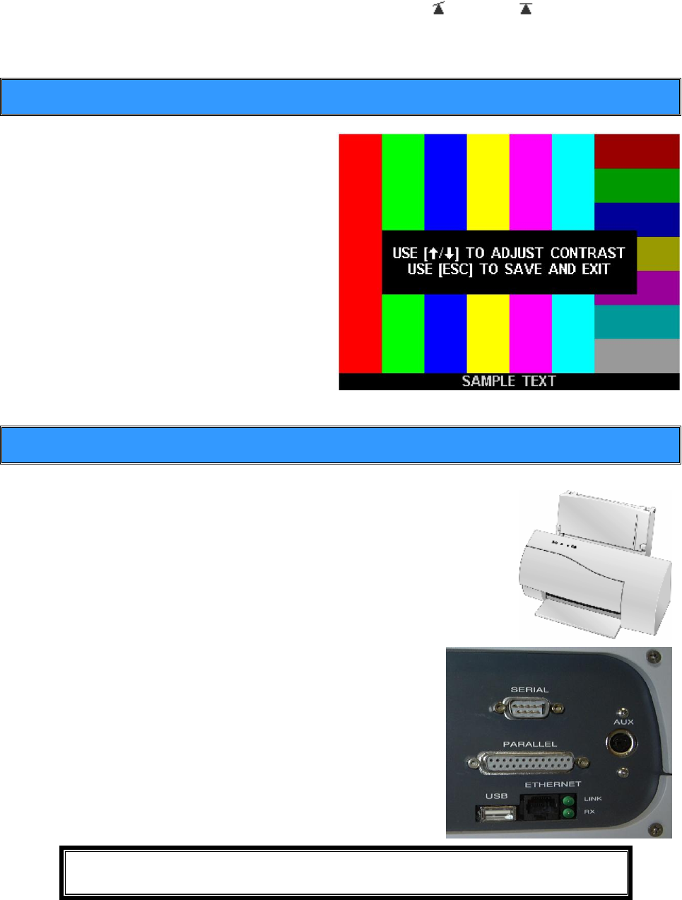
4.3. Contrast Adjustment
If necessary, adjust the display
contrast controls for better viewing of
the display. The left most soft key
below the display has the word
CONTRAST above it. Press this key
and the display changes to instructions
on setting contrast. Use the up and
down arrows on the key pad until the
display is acceptable and press the
[ESC] key to save the setting and exit
back to the Main Test Screen.
The LCD will darken after a few
minutes of inactivity but will brighten
with any key press.
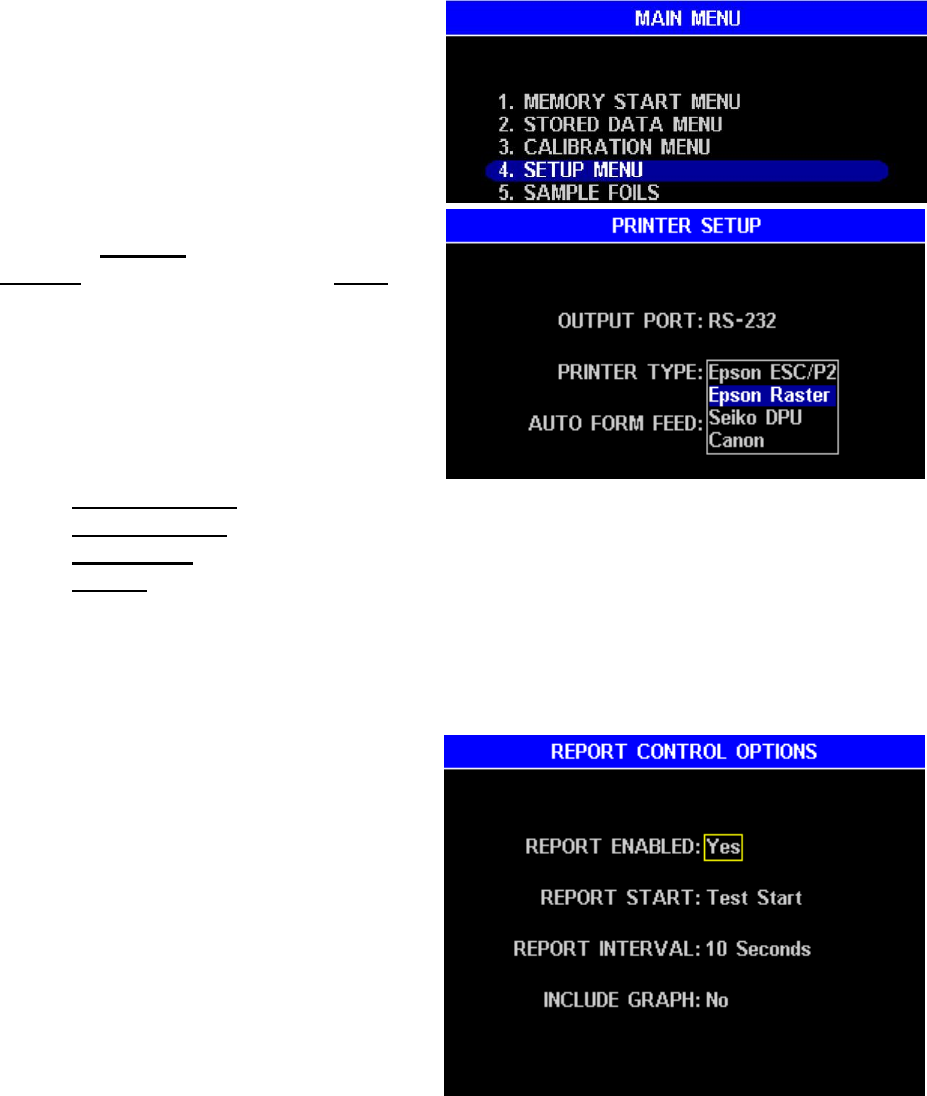
4.4. Connecting a Printer
An optional graphic capable printer is available from AZI (pictured
is printer example only). It connects to the parallel printer port at
the rear of the instrument. The content and time of printing for
each report can be custom configured from the menu system.
These same reports can be directed to a computer through the
RS-232 serial port at the back of the instrument.
Unpack the printer and cable. Load the paper according to
the instructions in the printer manual. Plug the large end
cable connector into its mating socket on the
printer, and the small end into its mating socket on
the back of the MAX 5000XL. Plug the power cord
into the printer, and into a GROUNDED power
receptacle.
Turn the printer power on. (On some older
printers, it is also necessary to place the printer
“On Line.”)
NOTE: The USB and AUX ports are not active at present. They will
be implemented in later revisions to the instrument.
AZI Customer Service 800-528-7411 or 602-470-1414 Page 17 of 92
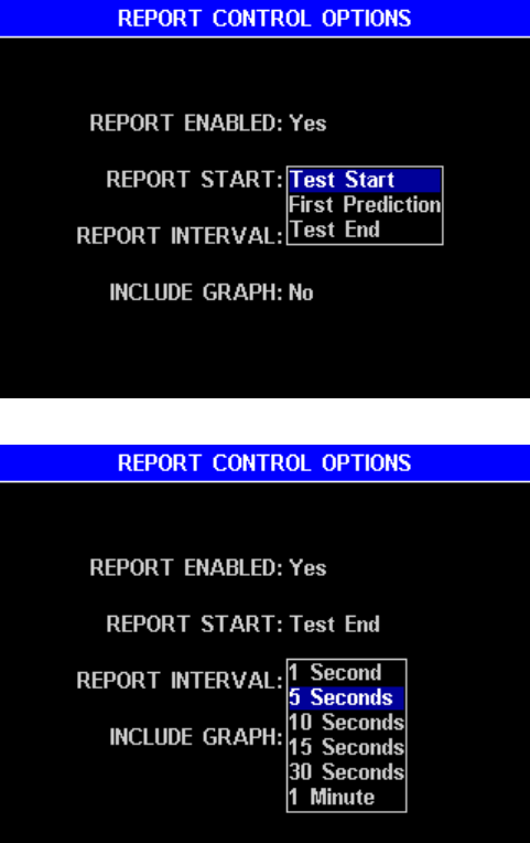
To set up the MAX 5000XL, begin at the Main
Test Screen and press [Menu], (center key
below display) to access the Main Menu.
Select SETUP MENU, press [ENT].
Select PRINTER SETUP, press [ENT].
Highlight Parallel for printer only,
RS-232 for computer only, and Both for
the printer and computer at the same
time. When the correct port selection is
highlighted, press [ENT] again.
Move the select box to PRINTER TYPE
and press [ENT].
Select the type printer you have and
press [ENT].
Epson ESC/P2 is for older style Epson printers
Epson Raster is for Epson C84 and newer.
Seiko DPU is for the small, thermal printer.
Canon is for the older Canon Bubble Jet line of printers.
Move the select bar to AUTO FORM FEED. Pressing [ENT] toggles between YES
and NO. Selection will depend on the printer used. Try Auto Form Feed YES for
most printers. If the printer seems to waste paper, switch it to NO.
Press [ESC] to return to the REPORT SETUP Menu.
Select REPORT CONTROL OPTIONS,
press [ENT].
Press [ENT] key to toggle between YES
and NO. Select YES if you want to send
test results and reports to a printer or
computer and NO to prevent sending
test results as outputs.
AZI Customer Service 800-528-7411 or 602-470-1414 Page 18 of 92
Move the selection box down to
REPORT START and press
[ENT]. Select between:
Test Start – begins to send
data at the start of the test,
First Prediction - begins to
send data as soon as the
instrument makes the first
prediction, or
Test End – waits to send data
until after the test is over and
then sends only the final results
of the test.
Press [ENT] to select your choice.
Move the selection box down to
REPORT INTERVAL and press
[ENT]. Select an interval that will
provide the test progress report
you need and press [ENT] again to
select your choice.
Move the selection box down to
INCLUDE GRAPH. Pressing
[ENT] will toggle between YES
and NO.
Select NO if you do not
need a printed graph of the
test.
Select YES if you have only
the parallel port selected and want to print the graphic plot of weight and
moisture/ash results for a test.
Press [ESC] to return to the REPORT SETUP MENU.
Select REPORT ITEMS TO PRINT. See page 52.
By default, all items are selected to print. If you do not want or need items, use the
arrow keys to select the item(s) and press [ENT] to toggle the check mark off. If
you later need the item, position the cursor in front of the item and press [ENT] to
toggle the check mark back on.
Press [PAGE 2] to see additional selections.
Press [ESC] until the Main Test Screen appears.
The output to the printer will be tested when a weight test is performed later. If you are
connecting a printer to an instrument that has been in operation, it is necessary to
1. Turn the MAX 5000XL OFF
2. Connect the printer to the MAX 5000XL.
3. Power ON the printer,
4. Turn the MAX 5000XL back ON to establish the communications.
5. Run a weight test and monitor the output to the printer.
AZI Customer Service 800-528-7411 or 602-470-1414 Page 19 of 92
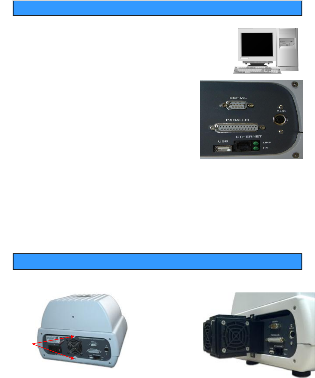
4.5. Connecting a Computer
If you wish to monitor the test with a computer, connect a null
modem cable to the serial connector at the rear of the instrument.
Use any serial port communications program (not provided) on
your computer to read the reports transmitted from the MAX
5000XL serial port. The content of each message can be selected
from the REPORT SETUP menu which is described on page 51.
The MAX 5000XL is equipped with RS-232 serial
communications available at a 9-pin standard
serial communications socket at the rear of the
instrument. The standard communications
parameters used are 115.2 kbits/s, no parity,
eight data bits, and one stop bit. Refer to your
computer communications program manual for
instructions on configuring the computer to read
this data format.
The MAX 5000XL does not test to see if the computer is actually connected or
ready to receive data. It does not respond to a request from the computer for
status information.
The MAX 5000XL can send data to both the RS-232 serial port and the parallel
printer port at the same time. However, the graph that can be printed by the printer
is not in a format that can be received by the computer. Therefore, the graph will
not be sent to the RS-232 serial port.
If you have any questions about connecting a printer or computer to your MAX 5000XL,
call AZI Customer Service at 800-528-7411 or 602-470-1414.
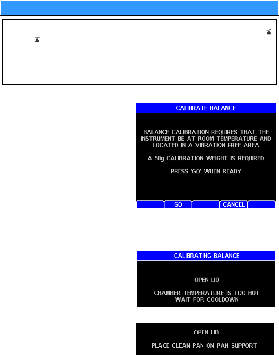
4.6. Connecting the External Filter Kit
An optional External Filter Kit (AZI #Y990-0210) is available for the MAX 5000XL for use
in dusty environments. Installation is simple and requires only a Phillips screwdriver.
Remove the two indicated screws, position the filter and
secure by replacing the two screws. NOTE: the side of the filter with the two notches
faces up. See External Filter Cleaning on page 81 for filter cleaning instructions.
Remove
these two
screws
Position filter
and secure
with the same
screws.
AZI Customer Service 800-528-7411 or 602-470-1414 Page 20 of 92
4.7. Calibrate the Balance - 50 gram weight
NOTE: The MAX 5000XL must be powered on until the balance temperature
stability icon in the lower left corner of the main screen changes from unstable
to stable to allow the balance to stabilize before beginning the balance
calibration. (See section 6.1 Balance Temperature Stability on page 64 for more
information). The unit should not be moved, jarred, or otherwise disturbed in any
way during the calibration period. A vibration-free table will aid the calibration
process. If vibration is excessive, the instrument will stop the calibration process
and indicate the reason.
The balance should be calibrated:
Immediately after initial setup and
warm-up,
Whenever the instrument is
moved,
Whenever a problem is suspected,
or
As your quality policy dictates.
From the Main Test Screen, press
[Menu].
Select the CALIBRATION
MENU.
Select BALANCE
CALIBRATION.
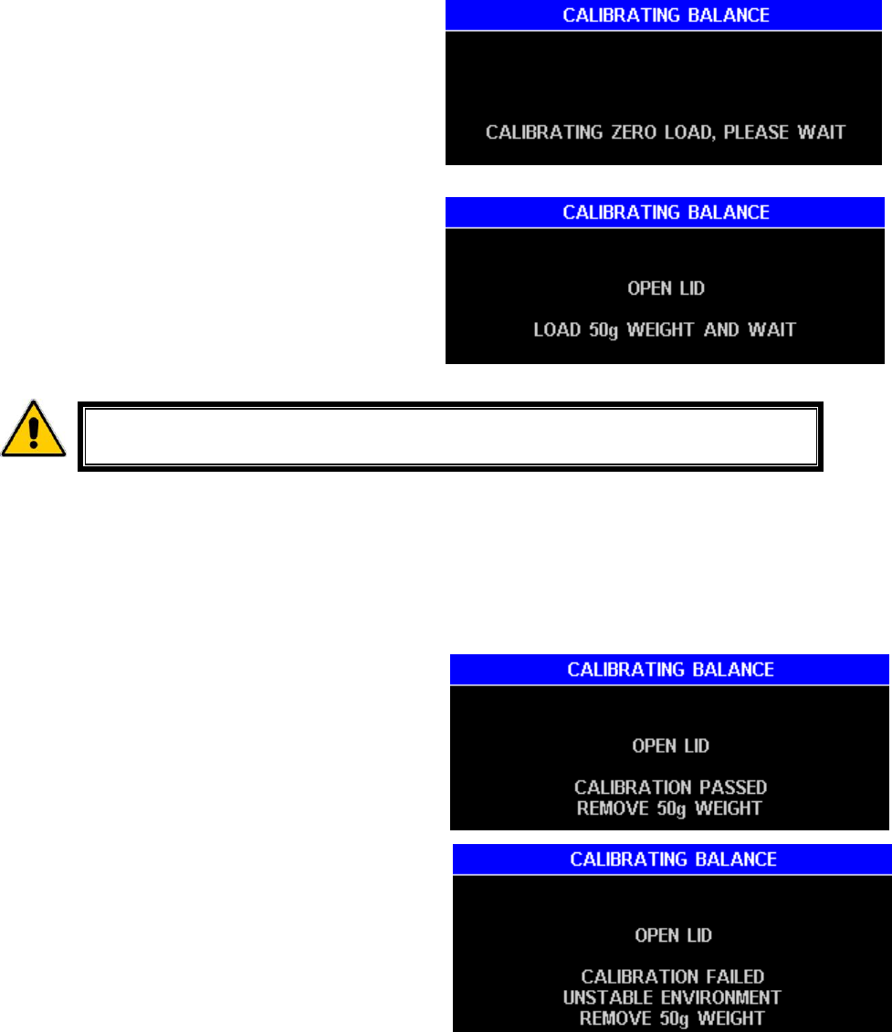
Select CALIBRATE BALANCE.
The first screen reminds the operator that the instrument must be free of vibration
during the calibration and that a 50-gram calibration weight must be available.
Press [GO].
If the chamber temperature is too hot,
the screen will prompt the operator to
“OPEN LID CHAMBER TEMPERATURE IS
TOO HOT WAIT FOR COOL DOWN”
If the chamber temperature is cool
enough to begin the calibration, one of
two prompts will appear:
If the lid is closed, the “OPEN LID”
“PLACE CLEAN PAN ON PAN
SUPPORT” prompt will appear.
If the lid is open, the “PLACE CLEAN
PAN ON PAN SUPPORT CLOSE LID”
prompt will appear.
AZI Customer Service 800-528-7411 or 602-470-1414 Page 21 of 92
After placing a clean pan on the
balance, close the lid. The screen will
display “CALIBRATING ZERO LOAD,
PLEASE WAIT.”
As soon as the tare is finished, the next
prompt appears.
Open the lid and gently place a
50-gram weight in the center of the
sample pan or press [ABORT] to
return to the menu.
Avoid excess pressure on the balance.
Use the tweezers included with the MAX 5000XL to gently place the
weight on the pan.
As soon as the instrument detects weight on the balance, the prompt “CLOSE LID”
appears.
With the lid closed, the prompt “CALIBRATING, PLEASE WAIT” appears.
At the conclusion of the calibration one of two prompts will appear, indicating the
PASS/FAIL condition of the calibration.
If the result is “PASS”, remove the
weights and the instrument is ready
for operation.
Press [PROCEED] to return to the
BALANCE CALIBRATION menu.
Press [ESC] three (3) times to return
to the Main Test Screen
If the result is “FAIL”, the calibration
was unsuccessful. Rerun the
calibration.
If the calibration fails again, contact
AZI Customer Service at
800-528-7411 or 602-470-1414.
AZI Customer Service 800-528-7411 or 602-470-1414 Page 22 of 92
4.8. Weight Test
To ensure proper calibration and become familiar with the instrument, run a weight test.
This test simulates moisture loss by the removal of one of two known weights. Both a
three and a five-gram weight are required.
Ensure that a clean, dry, empty
sample pan is placed on the pan
support.
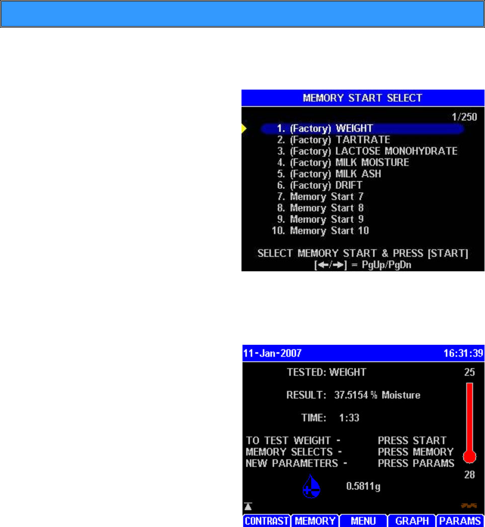
From the Main Test Screen, press
[MEMORY].
If the highlight bar is not already
there, highlight (Factory) WEIGHT
and press [START].
One of several prompts may appear
depending on the last measured
weight. Follow the instructions
given until the “OPEN LID” “ADD
SAMPLE…” prompt appears on the
screen. Open the lid and carefully
place both the 5-gram and the 3-gram weights near the center of the sample pan.
Close the lid.
After the Main Test Screen is displayed, gently open the lid, carefully remove the
3-gram weight, and gently close the lid.
Wait for the end of the test.
If this is the first test of the day,
discard the results of this test for
stability reasons and perform the
test again.
Record the final test result. The
value should fall between
37.4800% and 37.5200%.
If the results are out of tolerance,
repeat the balance calibration and
weight test. If the result is still out of
tolerance, call AZI customer service
at 800-528-7411 or 602-470-1414
for assistance.
AZI Customer Service 800-528-7411 or 602-470-1414 Page 23 of 92
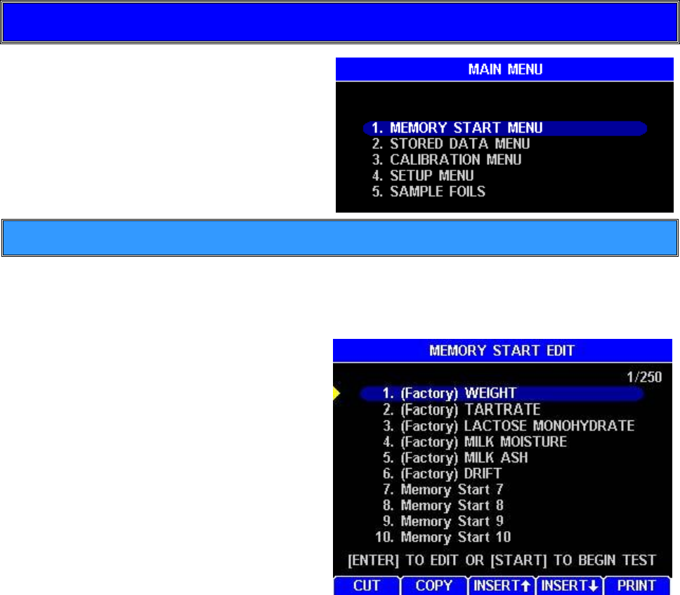
5. MAIN MENU
Press [MENU] to display the MAIN
MENU.
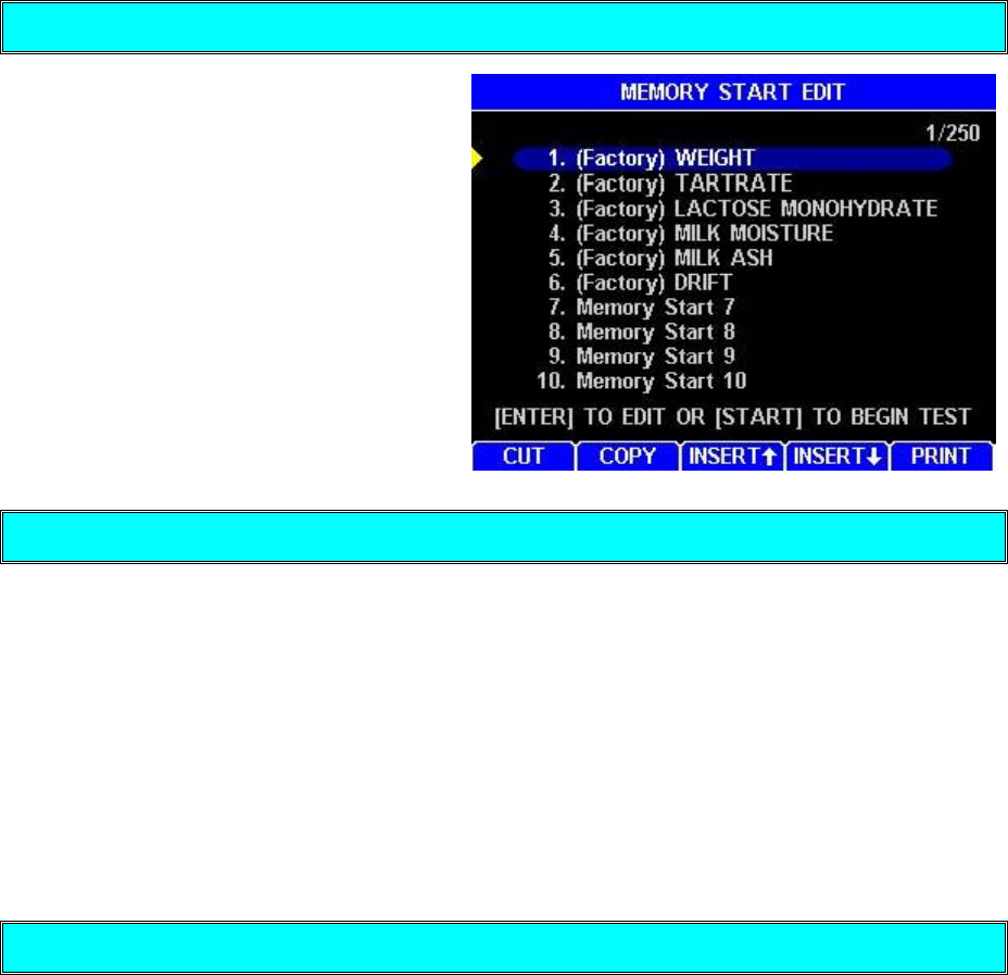
5.1. Memory Starts Menu
Memory Starts are stored test parameter sets. The MEMORY START MENU allows
access to the stored test parameter sets. This is where the contents of the stored
parameters may be printed out or changed.
The MEMORY STARTS are sequentially
numbered from 1 to the total of Memory
Starts entered into the instrument. The
figure to the right shows memory start 1 of
250 selected (1/250 in the upper right
hand corner). Pressing [INSERT ↑] or
[INSERT ↓] will insert a memory start
above or below the highlighted position
respectively. All other memory starts will
be moved down unchanged.
The “(Factory)” presets are for
standard tests to check the
performance and/or calibrate the
instrument.
The Up and Down Arrow Keys move the highlight one line at a time.
The keys at the bottom of the display allow the memory starts to be cut, copied,
inserted and printed. See page 35 and 36 for more information on CUT, COPY,
INSERT ↑, INSERT ↓, and PRINT memory starts.
AZI Customer Service 800-528-7411 or 602-470-1414 Page 24 of 92
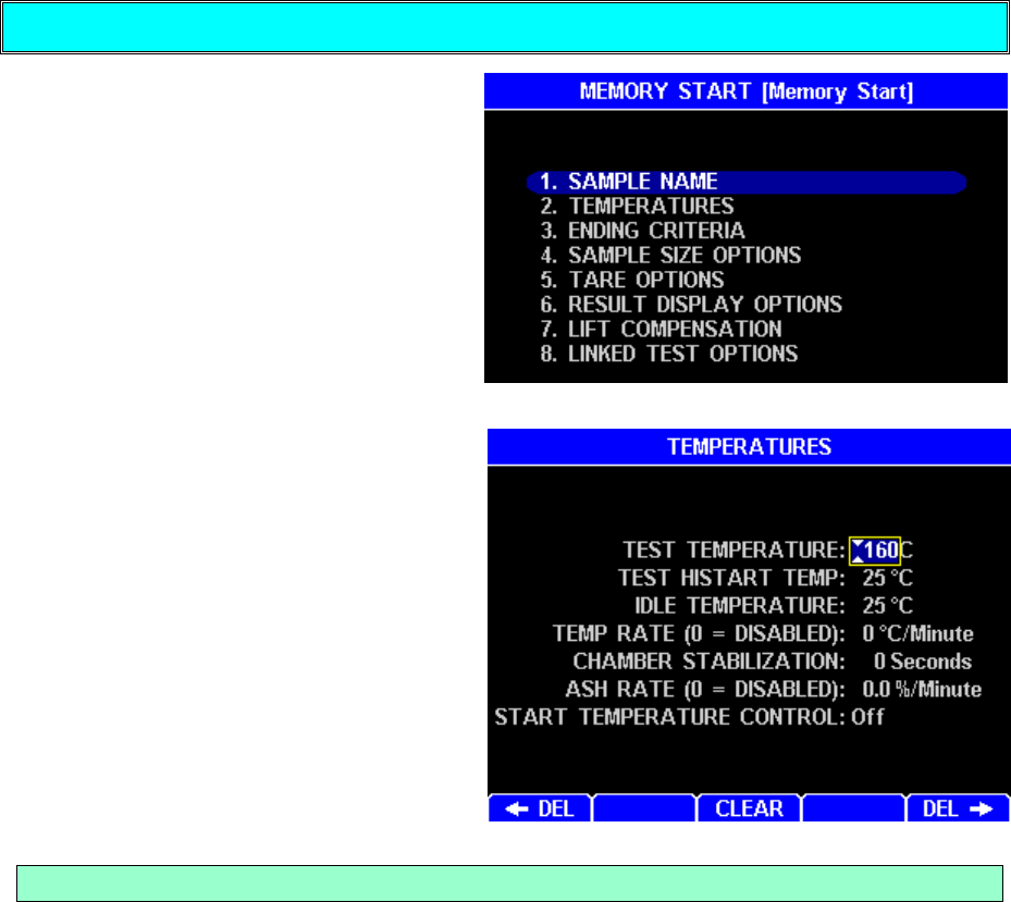
Editing Test Parameters
The memory start parameters may be
edited by highlighting a memory start
and pressing the [ENT] key. From the
eight (8) primary selections, there are
many other selections available to
allow changing the data stored and
altering the test characteristics.
The keys at the bottom of the
display aid the editing process.
[DEL] – deletes the character
to the left of the cursor
[CLEAR] – erases all characters
in the edit field
[DEL] - deletes the character
to the right of the cursor
[+/-] (Displayed only when
applicable) – changes the
polarity (pos/neg) of the number
If a number key is pressed without
moving the cursor, the current
content will be erased and the new
key press entered. Press [ENT] to
save the changes or [ESC] to abort
the change and restore the original
content.
Sample Name
This menu allows an alphanumeric identification for the test to be established. If the
name is not blank when selected, the entry may be deleted and new alphanumeric
characters entered. Note that the editing box will hold more characters than can be
displayed on the Main Test Screen. In addition, the box will hold more narrow letters
like “I” than wide letters like “M.” Edit the value to any desired name or number to
identify the product under test.
AZI Customer Service 800-528-7411 or 602-470-1414 Page 25 of 92
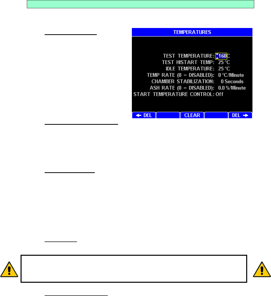
Temperatures
This menu gives access to three temperature parameters, an oven stable indication,
an ashing moisture rate control parameter, and an enable switch used during a test.
Test Temperature - The
current temperature setpoint is
displayed to the right of TEST
TEMPERATURE. Press
[ENT] and the cursor will be
positioned at the left most
significant digit. Use the
number keys to enter the
desired test temperature.
When finished, press [ENT] to
stop editing and save the new
figure or [ESC] to cancel the
change.
Test HiStart Temperature – When active, the HiStart temperature is used at
the start of the test, and the test continues at that temperature until the rate of
moisture loss falls to half of its peak value. The heater then changes to the Test
temperature for the remainder of the test. This shortens a long test and may be
useful for tests > 15 minutes. When used, try a HiStart temperature 25ºC
above the Test temperature. To deactivate the HiStart feature, set the HiStart
temperature to 25ºC.
Idle Temperature - The temperature that is maintained by the instrument
between tests. This speeds testing, by decreasing the time required to heat the
sample chamber at the beginning of the test. It can save 10 to 120 seconds of
test time if properly used. A common idle temperature value is 50ºC or 80ºC for
most products. For plastics, a 100ºC idle is desirable. For ashing, a 100ºC idle
may be desirable to reduce time between tests. Any value between room
temperature and 300º C can be used. Experiment to see what value is best for
your application. Too high a value will cause low results because the sample is
evaporating while the basis weight is being measured at the beginning of the
test.
Temp Rate - The temperature is controlled to the specified rate while ramping
to the setpoint. Set to 0 to disable. Do not use this in conjunction with ash rate.
Chamber Stabilization - When a number other than zero is entered, a
chamber stability warning will appear at the bottom of the Main Test Screen.
Although this function will not prevent tests from being run, the results from
extremely low/high moisture samples will be improved if the test is not started
until the display indicates “CHAMBER STABLE”. For ultra low moisture samples,
5-minute stabilization will help repeatability. For ultra low ash samples,
10-minute stabilization will help repeatability.
TEMP RATE MUST NOT BE USED AT ASHING TEMPERATURES BECAUSE
IT WILL NOT PREVENT SAMPLE IGNITION AND HEATER DAMAGE CAN
RESULT. INSTEAD, USE ASH RATE TO PREVENT SAMPLE IGNITION.
AZI Customer Service 800-528-7411 or 602-470-1414 Page 26 of 92
The possible displays are:
CHAMBER STABLE - The oven has been at a stable temperature for at
least the time period set.
CHAMBER STABILIZING: LOW TEMP - Oven is below temperature
setpoint.
CHAMBER STABILIZING: HIGH TEMP - Oven is above temperature
setpoint.
CHAMBER STABILIZING: xx:xx - Oven temperature is within the correct
range and the time remaining until specified time is displayed.
Ash Rate – This is used for high test temperatures that will ignite a sample.
YOU MUST USE THIS TO PREVENT HEATER DAMAGE.
The Ash Rate value is a rate of moisture loss used to limit the rate of increase
in oven temperature to slow ignition and prevent flaming. The normal
temperature setpoint is limited to keep the moisture loss at less than the set ash
rate. For example, if an ash rate of 7 %/Minute is used, the temperature
increase is controlled to maintain a ≤ 7 %/Minute moisture loss during the test.
Start Temperature Control - Prevents a test from starting if the chamber
temperature is more than two degrees hotter or colder than the IDLE
TEMPERATURE. This feature can improve the standard deviation of results
of some temperature-sensitive materials.
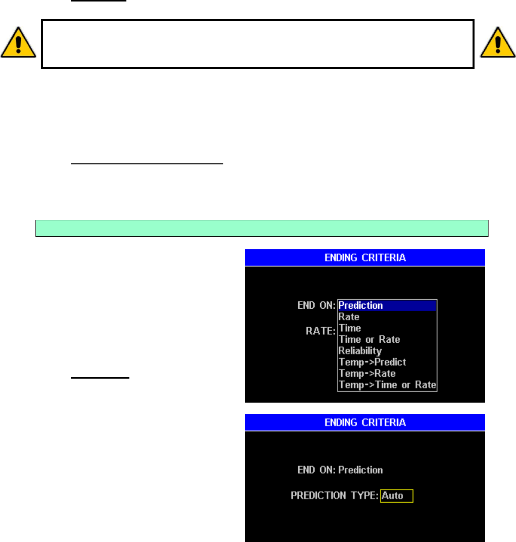
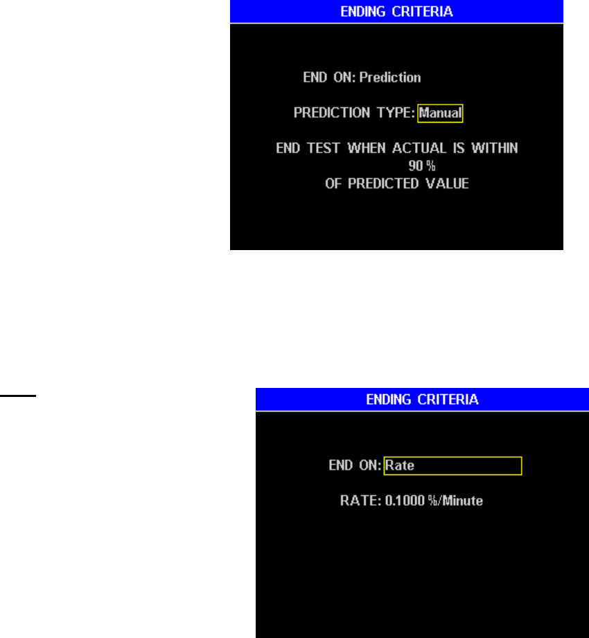
Ending Criteria
The criteria used by the instrument to
automatically end a test. This feature
makes it unnecessary for the operator
to monitor the analyzer while it is
performing a test. Selecting this
option will display the ending criteria
options.
Prediction - The MAX 5000XL
uses an advanced version of
the AZI moisture prediction
algorithm to automatically end
each test early to speed test
results. The prediction method
relies on the fact that most
samples exhibit a weight loss
trend such that the rate of
volatilization is proportional to
the amount of volatile material
remaining in the sample.
TO PREVENT SAMPLE IGNITION AND POSSIBLE HEATER DAMAGE,
USE ASH RATE, NOT TEMP RATE, AT ASHING TEMPERATURES. TEMP
RATE WILL NOT PREVENT SAMPLE IGNITION.
AZI Customer Service 800-528-7411 or 602-470-1414 Page 27 of 92
When the prediction is sufficiently reliable, the test ends and the predicted
result is displayed, stored in the instrument, and printed if an accessory printer
is enabled and attached. Proper selection of the ending criteria can greatly
improve the test times and repeatability.
Auto - The instrument
monitors the progress of
moisture determination and
automatically selects the
ending criteria most
appropriate to the test under
way.
Manual - In a few
instances, best
performance will be
achieved by adjusting the
ending criteria.
This ending criterion is
called the Reliability, and
is activated when the predicted moisture value and the actual moisture loss
are sufficiently close together. The number displayed is a percentage,
equal to the actual moisture loss divided by the predicted moisture, times
100%. For example, if 90% is entered, the test will end when the actual
moisture loss is within 90% of the predicted moisture.
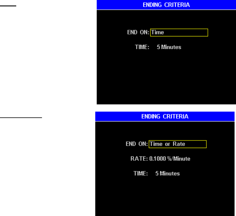
Rate - This feature ends the test
when the weight loss rate falls
below a selected value. This
value is a “percent per minute.”
For example, entering 0.100
means that the test will end when
the rate of change of the actual
weight loss is less than 0.100 %
of the original sample weight per
minute.
The instrument's program
assumes that the sample
contains volatile material that
will completely evaporate after some time. It further assumes that, at first,
the rate will increase to a maximum point, and then gradually decrease to
zero. Selecting some threshold rate value will cause the test to end before
the sample is completely dry. Rate is useful to profile a sample's weight
loss. Some applications are faster in the rate ending criteria. Others are
faster in the prediction ending criteria.
AZI Customer Service 800-528-7411 or 602-470-1414 Page 28 of 92
Some samples contain more than one volatile material, for example, nylon
resins with large amounts of unpolymerized material (Caprolactam). In
these cases, the rate will fall to some fixed value when all the moisture is
evaporated but while the monomer is still evaporating. The graphical
display available from the Main Test Screen is of great help in visualizing
these cases. The rate ending criteria, if set above the rate of monomer
volatilization, may give the best results.
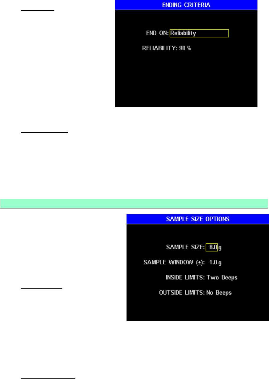
Time - This feature places a
time limit on a test. The test
will end when a selected
amount of time has passed.
Fixed time tests are
seldom superior to the
prediction algorithm, but
can be useful when
conducting application
characterization tests, or
when investigating long
term stability of the
instrument.
Time or Rate – This feature
is used during tests when a
change in moisture may not
occur. When the moisture
characteristics of a sample
are not known, linked tests,
with slightly higher
temperatures for each
successive test may be used.
With the “Time or Rate”
selection and linked tests
enabled, testing will continue
for the set amount of time
and then start the next test in
sequence. If a moisture loss occurs, the test will end on the rate criteria and the
next test will begin.
AZI Customer Service 800-528-7411 or 602-470-1414 Page 29 of 92
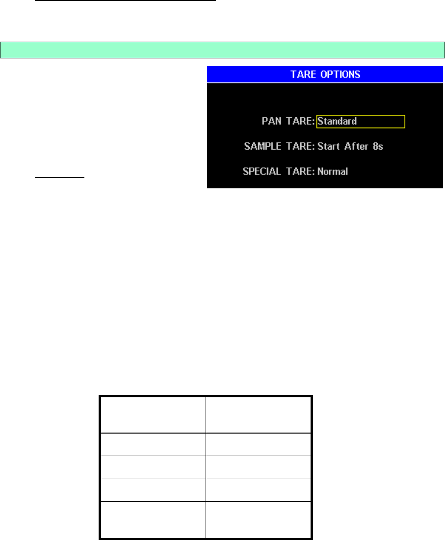
Reliability – This feature is
similar to Rate but is based
on a percent of accuracy.
With reliability set to 99%,
the test would end when the
actual moisture loss was
within 99% of the predicted
result. A value may be set
that would give exceptional
results when the actual
result is within 90 to 99
percent of the predicted
result. This ending criterion
is less dependent on actual moisture loss than Rate.
Temp Then … – These features are used when rate or predict criteria alone
would end the test after the release of free or bound moisture but before the full
temperature is reached. The MAX 5000XL first checks to see that the
temperature is within two (2) degrees of the test temperature before checking
for the other criteria as previously described. This can be helpful for ashing,
which takes a while to reach the final temperature, and testing ultra low
moisture samples, which don’t readily release moisture at the beginning of the
test.
Sample Size Options
This feature enters a target sample
size and the minimum and maximum
sample range. Sample size ranges
can be programmed from 0.1 gram to
99.9 grams. The total difference in
values between size and window must
be between 0 grams minimum and 100
grams maximum.
Sample Size - The sample size
should be consistent for all tests
on a particular product in order
to get the best standard
deviation possible. High volatile
materials, such as coatings, typically require smaller sample sizes (one to three
grams). Low moisture materials, such as plastic resins, typically require larger
sample sizes. The instrument is optimized for low moisture testing with a 30g
load. Ashing typically requires a smaller sample size to reduce the residue that
is emitted during testing. The instrument is optimized for ashing with a 4g load.
Contact your technical sales representative for appropriate sample sizes.
Sample Window - The number entered sets the allowable tolerance of the
sample to be loaded.
AZI Customer Service 800-528-7411 or 602-470-1414 Page 30 of 92
Inside Limits and Outside Limits - Selections of no sound, one beep, two
beeps or three beeps may be programmed to have the instrument indicate
when the weight of the sample is inside or outside the sample weight tolerance.
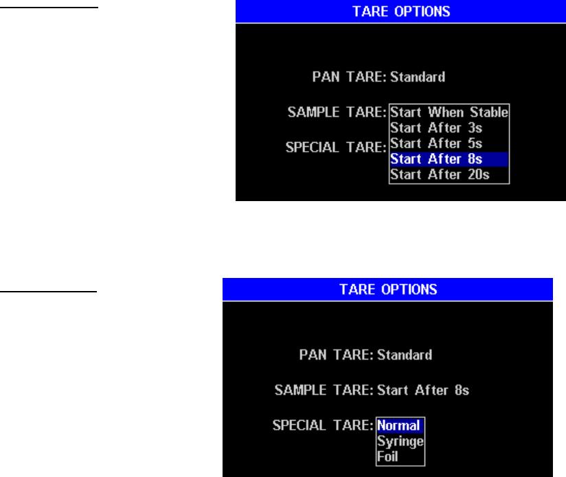
Tare Options
Two tare options define how stable the
balance must be before a test will
start. The third tare option is labeled
Special Options and is used to tare a
syringe, foil tray or other lightweight
device used to carry or hold the
sample on the pan.
Pan Tare – Records the
average empty pan weight after
ensuring that its weight is sufficiently stable over a programmable period of
time. Taring continues until the weight is found stable (≤ 0.2mg deviation) over
the programmable period of time. Temperature fluctuations occur in the test
chamber, dependent on a number of different criteria such as previous test
temperature, the amount of cool down time between tests, and the current idle
temperature. The temperature fluctuations cause the balance readings to drift
during taring and are reflected as an error in the final value. Because the
conditions that cause the temperature fluctuations are not always constant, the
error often appears as a higher standard deviation for a series of tests on a
particular sample.
The Pan Tare option has four (4) user selections to adjust the relationship
between tare time and tare error to improve overall operation for a given
product or purpose. The following table summarizes the menu choices and the
parameters associated with each choice.
MENU
CHOICE
MINIMUM TARE
TIME
FAST
6 seconds
STANDARD
8 seconds
LOW MOISTURE
10 seconds
ULTRA-LOW
MOISTURE
12 seconds
The ULTRA-LOW MOISTURE option should be used for samples with
moisture/solids/ash content between 0.005 and 0.2 percent. This option may
be used to improve accuracy for samples with moisture content in excess of 0.2
percent but will increase the overall testing time.
AZI Customer Service 800-528-7411 or 602-470-1414 Page 31 of 92
Sample Tare – Records the
average initial sample weight
during a programmable period
of time. After lid closure, there
is a 7 second delay before the
sample tare time begins.
There are five (5) possible
choices under this menu. The
factory default is Start After
8s.
Start When Stable –
Taring continues until the
weight is found stable (≤ 0.2mg deviation) over 4s of time.
Start After (selectable) Seconds: Test starts after (selectable)
seconds of averaging, i.e. 3s, 5s, 8s, or 20s
Special Tare - There are
three special tare options.
Two of these set up
operations that are not
required for most types of
testing.
Normal Tare – selects
normal operation of tests.
Syringe Tare – Used to
obtain an accurate
sample tare for materials
that rapidly evaporate during the sample loading process. An external
balance with 0.0001-gram (0.1 mg) resolution is used to weigh the syringe
before and after loading, which are entered into the MAX 5000XL. The
difference between the loaded and empty syringe weights is start weight.
Foil Tare – is used when a sample of sprayed material, such as paint, is to
be tested. Up to 50 pieces of foil can be pre-weighed before actual testing
begins. The alphanumeric identity of each foil is stored in memory until it is
replaced by other foil tare entries. During a test, the ID of the foil is entered
from a menu of stored foils. The weight of the foil is subtracted from the
measured weight, giving the true weight of the sprayed sample. (See
section 6.5 for more information.)
AZI Customer Service 800-528-7411 or 602-470-1414 Page 32 of 92
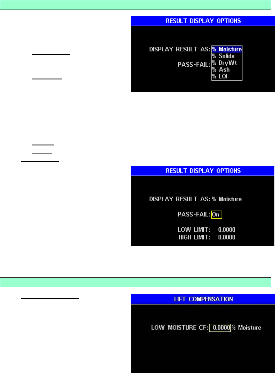
Result Display Options
DISPLAY RESULT AS: Selects
the final display value of
moisture, solids or dry weight,
ash or LOI.
% Moisture - Test results are
displayed as a percentage of
weight loss.
% Solids - Test results are
displayed as a percentage of
weight remaining. The
instrument is optimized to run in %Solids for samples > 99.5% volatiles.
% Dry Weight - Test results are displayed as a dry weight basis.
% Dry Weight = ((WINITIAL – WFINAL) / WFINAL) * 100
Note that the dry weight value ratio can exceed 100%, and often does in
applications such as soil and forest fuels analysis.
% Ash – Test results are displayed as a percentage of weight remaining.
% LOI – Test results are displayed as a percentage of weight loss.
PASS-FAIL – Toggles ON or OFF
Low Limit – sets the lowest
acceptable limit for the test.
A final test value below this
figure will cause a FAIL
indication to appear on the
display and, if selected in
setup, on printed reports.
High Limit – sets the highest
acceptable limit for the
moisture test. A final test
value above this figure will
cause the FAIL indication to appear on the display and, if selected in setup,
on printed reports.
Low Moisture CF
Low Moisture CF - For
extremely low moisture products,
a calibration factor can be used
to align MAX 5000XL results to
the reference standard. The
percentage difference between
the stabilized MAX 5000XL
mean values and the reference
standard is entered as the LOW
MOISTURE CF. This feature is
not typically used.
AZI Customer Service 800-528-7411 or 602-470-1414 Page 33 of 92
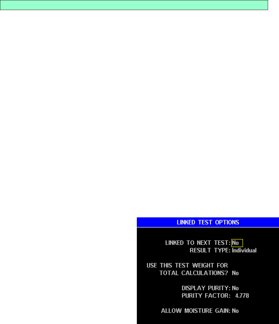
Linked Test Options
Linking tests enables multiple adjoining memory starts to be run together as one test.
Increasing temperatures, rates, times, etc., may be selected to monitor the progress
of moisture loss for research and/or control purposes. In some materials, such as
gypsum powder, moisture occurs in more than one molecular state, usually free water
and one or two bound water states. A third condition exists in the ashing process
when other components of the sample are driven off at very high temperatures and
only the ash remains.
The Linked Test Option will also prevent rehydration of the sample between tests. As
the test for free moisture is completed, the next memory start in sequence will be
initiated. This subsequent memory start must contain the parameters for the bound
water test. As this test ends, the next memory start may be initiated and so on for as
many links as needed for the process. The sample integrity will not be compromised
between tests since the instrument’s lid is not opened.
Free water evaporates from the sample at relatively low temperatures, typically
40 to 80 C.
Bound water however requires higher temperatures, some around 135 C and
others around 240 C to break the molecular bonds.
The MAX 5000XL also provides temperatures to 600 C for ashing purposes.
The linked tests may also be helpful in determining the temperature at which moisture
is freed in unknown sample material. Setting the temperature a few degrees higher in
each succeeding test will eventually reach a point of weight loss due to evolved
moisture.
Link To Next Test - To run a single
test or to make this the last segment of
linked series, toggle this parameter to
NO.
Result Type - The two selections for
result type offer an Individual
determination for this memory start or
a Total determination of two or more
linked memory starts.
Individual Result – This selection
provides the result of this test when
two or more tests are linked.
Total Result – This selection
provides the result using the start
weight of a preceding memory start and the final weight of this memory start.
AZI Customer Service 800-528-7411 or 602-470-1414 Page 34 of 92
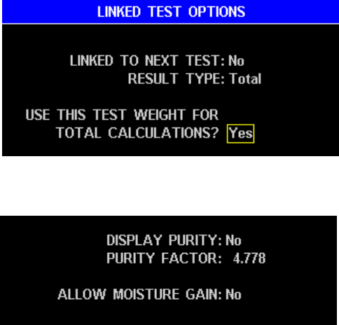
Use This Test Weight For Total Calculations?
Toggle this parameter to YES
if this test’s starting weight is to
be used in Total Result
calculations for this or later
linked tests. The starting
weight for this test will be used
for total calculations until
another YES is encountered.
Note the starting weight of the
first test in a linked series is used for total calculations until a YES is
encountered.
Purity Factor – Toggle this
parameter to YES if a value,
provided by the user, is to be
entered as a parameter for the
purity calculation. The default
number is 4.778, which is the
purity factor for gypsum. The purity result is Purity Factor times the Moisture loss.
Allow Moisture Gain - When testing some materials, the linked test option is
used. The first test is the free moisture test, which drives off any free moisture.
However, some materials if already dried might actually collect moisture during this
test. With the Allow Moisture Gain enabled, the collected moisture will be reported.
Ending Criteria for this test is usually “Rate or Time”. If “Rate” is used the test
would never end if the sample gained moisture.
AZI Customer Service 800-528-7411 or 602-470-1414 Page 35 of 92
CUT Memory Start
This command removes a memory
start, which can be optionally inserted
at another location. Use this
carefully. The “(Factory)” memory
starts cannot be deleted with this
option.
COPY Memory Start
To quickly create a new set similar to an old one, use [COPY] from one location, move
the highlight bar to the desired location and [INSERT↑] or [INSERT↓] into a new
location.
Highlight the memory start set you wish to copy.
Press [COPY].
Using the Up and Down Arrow Keys highlight the location where you want the
new memory start to be and press [INSERT↑] or [INSERT↓].
The contents of the locations are safe. Memory starts above the insert will not be
affected and memory starts below the insert will be moved down the list
INSERT Memory Start
Pressing [INSERT↑] or [INSERT↓] will insert a new memory start either above or
below the cursor location and move the following memory starts down.
AZI Customer Service 800-528-7411 or 602-470-1414 Page 36 of 92
PRINT Memory Start
This command prints the stored parameters. All of the numbered Memory Start Sets
are printed, giving the values of the parameters shown below in the print out example.
COMPUTRAC MAX 5000XL MEMORY START REPORT
COMPANY: AZI Preferred Customer UNIT #: 500061
-----------------------------------------------------------------------------
# ID TST IDL HST SSZ SWN T/I TOT EC MODE
-----------------------------------------------------------------------------
1 WEIGHT 105 25 25 8.0 1.0 I No Rate 1.0000%/Minute
2 TARTRATE 150 80 25 8.0 1.0 I No Rate 0.0250%/Minute
3 LACTOSE MONOHYDR 135 80 25 4.0 0.5 I No Rate 0.1000%/Minute
4*MILK MOISTURE 210 50 25 5.0 0.5 I No Rate 0.1000%/Minute
5 MILK ASH 575 25 25 5.0 0.5 T No Rate 0.0500%/Minute
6 DRIFT 200 80 25 50.0 1.0 I No Time 20min
7 Memory Start 7 160 25 25 8.0 1.0 I No Rate 0.1000%/Minute
-----------------------------------------------------------------------------
128 Memory Start 160 25 25 8.0 1.0 I No Rate 0.1000%/Minute
129 Memory Start 160 25 25 8.0 1.0 I No Rate 0.1000%/Minute
250 Memory Start 160 25 25 8.0 1.0 I No Rate 0.1000%/Minute
Page #0X
NOTE: If all locations have been entered, a full printout of the
Memory Starts will take five pages to print all 250 sets, otherwise
only those Memory Starts that have been entered will be printed.
The column headings are abbreviations for the following:
#
Identification Number of the Memory Start Set
ID
Identification Name of the Memory Start Set (an * in the list
indicates the set is linked to the next Memory Set)
TST
Programmed Test Temperature
IDL
Programmed Idle Temperature
HST
Programmed HISTART Temperature
SSZ
Sample Size
SWN
Sample Window
T/I
Test selection using Total or Individual test result
TOT
Test calculation based on total weight
EC
Ending Criteria
MODE
Details for selected ending criteria
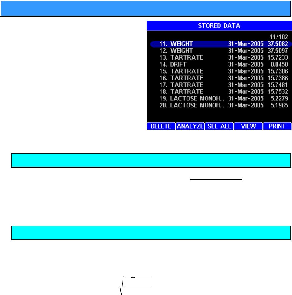
AZI Customer Service 800-528-7411 or 602-470-1414 Page 37 of 92
5.2. Stored Data Menu
This function is used to work with data
stored in the instrument from past tests.
Up to 1,000 test results and 100 graphs
can be stored before the oldest is "pushed
out" (overwritten). To access this function,
go to the Main Menu and select the
STORED DATA MENU. On 21 CFR, Part
11 compliant units, the DELETE is not
available.
Delete Stored Data (Not available on 21 CFR, Part 11 compliant units)
This function is used to delete individual results and is non-reversible. Normally
results are deleted to make management of the data easier. If the test results need to
be saved, they should first be printed or stored in a computer file. Moving the selector
bar to a particular test and pressing [DELETE] will erase the record so be careful! If
the list is empty, the screen will show EMPTY.
Analyze Stored Data
Mean, Standard Deviation, and Relative Standard Deviation are calculated using the
following formulas available on many hand calculators.
Mean = total of results divided by number of results.
Standard Deviation =
1-n
x-x 2
)(
Relative Standard Deviation expressed as percentage = Standard
Deviation divided by Mean, multiplied by 100%
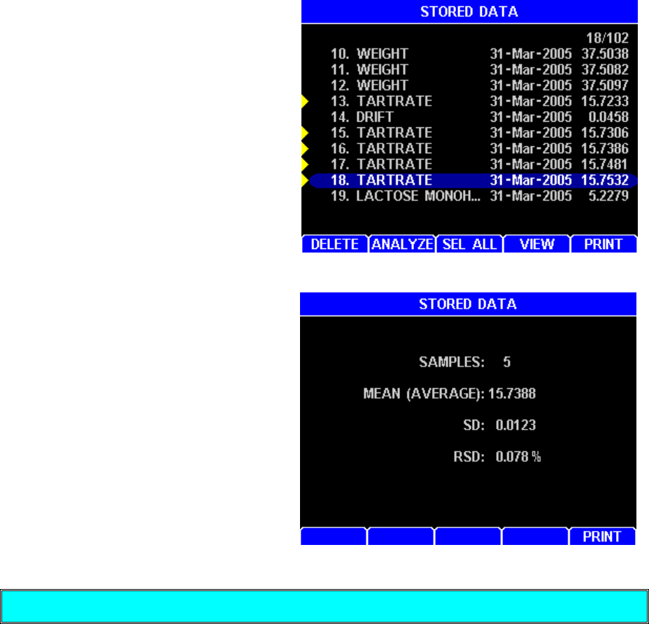
AZI Customer Service 800-528-7411 or 602-470-1414 Page 38 of 92
To analyze a set of data:
Use the arrow keys to highlight the
data items to be included in the
analysis, and press the [ENT] key.
Notice that each selected item is
marked with a triangular symbol at the
left of the data item. If one has been
designated in error, move the selector
bar to it and press the [ENT] key to
deselect (and unmark) it. When all
desired items are selected, press
[ANALYZE].
The screen will immediately display
the number of samples, mean,
standard deviation, and relative
standard deviation of the selected
data set. To the right is an example
of a calculated report. This report can
be printed by pressing [PRINT].
Press the [ESC] key to return to the
previous menu.
Select All Data
All stored data can be selected to be deleted, analyzed, viewed or printed. To select
all stored data press [SEL ALL].
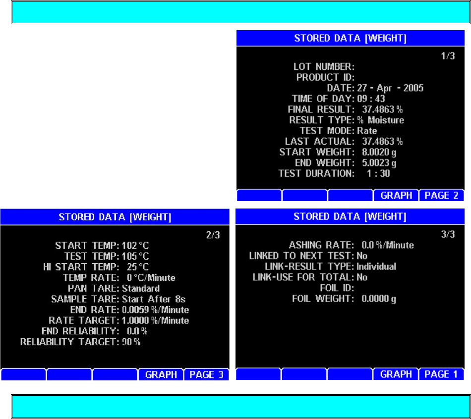
AZI Customer Service 800-528-7411 or 602-470-1414 Page 39 of 92
View Stored Data
This function is used to view a list of
results for a selected test. Move the
selector bar to a particular test and
press [VIEW] to display the data. There
are three (3) pages of data.
Print Stored Data
Stored data can be printed to a parallel printer attached to the MAX 5000XL (See page
16). That same data can also be routed to a computer (See page 19). To print stored
data, press [PRINT] on the STORED DATA MENU. Only report items that have been
selected in the REPORT ITEMS TO PRINT menu will print (See page 52).
AZI Customer Service 800-528-7411 or 602-470-1414 Page 40 of 92
5.3. Calibration Menu
Balance Calibration
Balance calibration is explained and performed as part of instrument setup, see page
20. The sequence is repeated here for continuity.
The balance should be calibrated:
If the instrument has been turned off for several hours or in storage,
After the instrument is moved,
Whenever a problem is suspected, and/or
As often as required by your quality policy.
NOTE: The MAX 5000XL must be powered on until the balance
temperature stability icon in the lower left corner of the main screen
changes from unstable to stable to allow the balance to
stabilize before beginning the balance calibration. (See section 6.1
Balance Temperature Stability on page 64 for more information).
The unit should not be moved, jarred, or otherwise disturbed in any
way during the calibration period. A vibration-free table will aid the
calibration process. If vibration is excessive, the instrument will
stop the calibration process and indicate the reason.
Calibrate Balance
From the Main Test Screen, press [Menu].
Select the CALIBRATION MENU.
Select BALANCE CALIBRATION.
Select CALIBRATE BALANCE.
Press [GO]. Follow the prompts to complete the calibration.
The first prompt is “OPEN LID” and “PLACE CLEAN PAN ON PAN SUPPORT”
After placing a clean pan on the pan support and closing the LID, the screen will
display “CALIBRATING, PLEASE WAIT.”
As soon as the tare is finished, the next prompt, “OPEN LID” and “LOAD 50G WEIGHT
AND WAIT,” will appear.
As the lid is opened, the screen prompts: “LOAD 50G WEIGHT AND WAIT.”
Avoid excess pressure on the scale. Use the tweezers included
with the MAX 5000XL to gently place the weight on the pan.
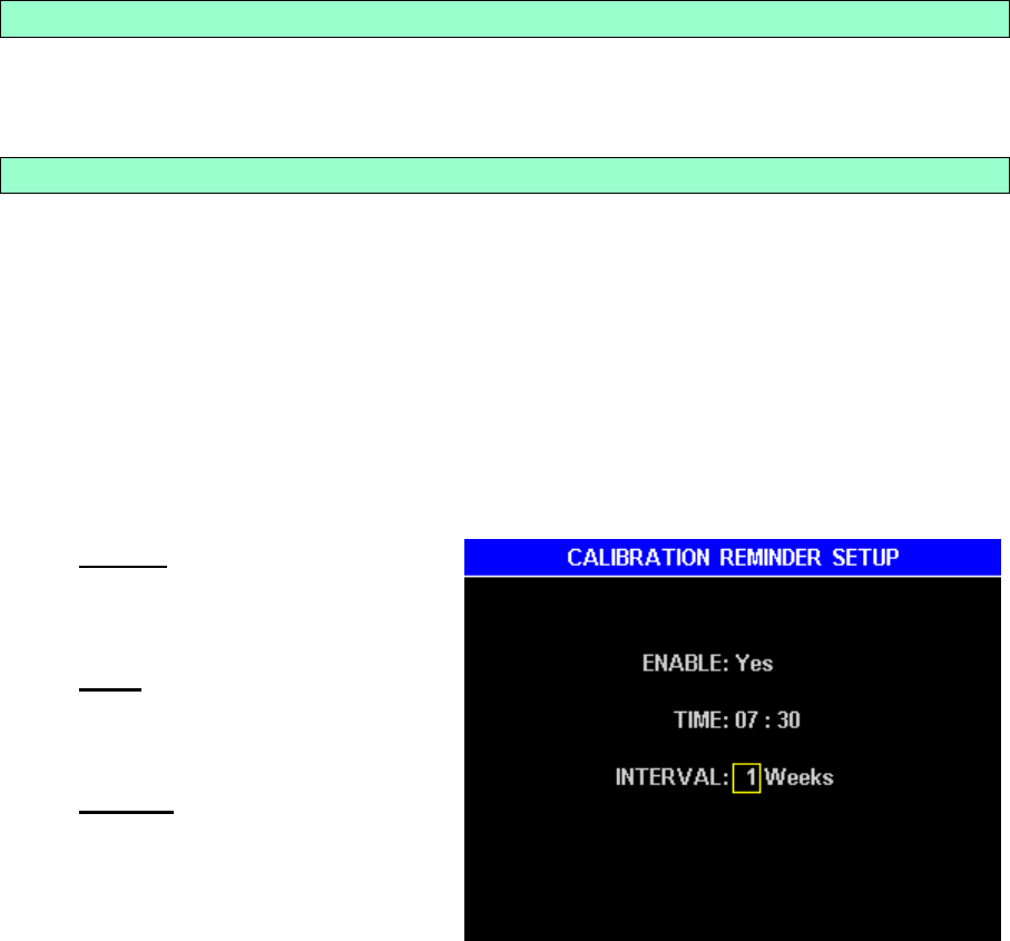
AZI Customer Service 800-528-7411 or 602-470-1414 Page 41 of 92
As soon as the instrument detects weight on the balance, the prompt “CLOSE LID”
appears.
With the lid closed the prompt “CALIBRATING, PLEASE WAIT” appears.
At the conclusion of the calibration, the “OPEN LID” “REMOVE WEIGHT” prompt
appears with a PASS/FAIL indication of the calibration success.
If the result is “PASS”, open the lid; remove the weight and press [PROCEED] to
continue.
If the result is “FAIL”, the calibration was unsuccessful. Rerun the calibration.
If the calibration fails again, contact AZI Customer Service at 800-528-7411 or
602-470-1414.
Press the ESC key three (3) times to return to the Main Test Manu.
View Calibration Report
When VIEW CALIBRATION REPORT is selected, the last balance calibration date will
be displayed.
Calibration Reminder Setup
A prompt is available to remind you when scheduled calibrations are due. The default
factory settings are:
ENABLE - No
TIME – 00:00
INTERVAL - 0 Weeks
To turn the prompt on, off, or adjust the interval; go to the Main Test Screen and select in
order: MENU, CALIBRATION MENU, BALANCE CALIBRATION, and CALIBRATION
SETUP REMINDER
Enable – Toggle to YES to
enable the prompt or NO to
prevent the prompt from
appearing.
Time – The time the prompt is
to appear, usually the start of
the shift (using a 24 hour
format).
Interval – The interval
between calibrations (in
weeks). If the interval is set to
“00”, the reminder will occur
daily.
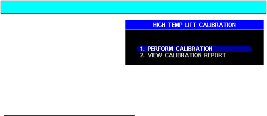
AZI Customer Service 800-528-7411 or 602-470-1414 Page 42 of 92
High Temperature Lift Calibration
The MAX 5000XL High Temperature
Lift Calibration routine records the lift
that is created in the heat chamber
from air currents. The calibration will
significantly improve low ash accuracy
and unit to unit correlation.
Since the calibration is performed at 600°C and ramps the temperature to 600°C twice
with a room temperature cool down in between, it takes about 2 ½ hours to complete
the calibration. The calibration can be run at night if the room temperature is similar
at night as during the hours of operation. If a fume hood is used during testing, then
use a fume hood during calibration. Note, the High Temperature Lift Calibration runs
at 600°C, so it will clean the oven chamber.
The calibration should have a lift at 30min of -0.0040g to -0.0060g and have a heater
power of 65% to 85%.
The 600°C calibration is scaled to provide compensation at other test temperatures.
This calibration is performed at the factory and can be routinely performed by the
customer. The calibration report can be printed before and after the calibration to
provide a record of the calibration difference. If there is a minimal difference, then you
can increase you calibration period and vice versa.
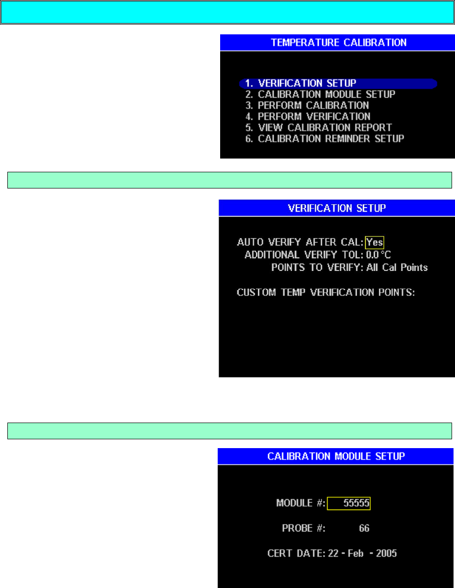
AZI Customer Service 800-528-7411 or 602-470-1414 Page 43 of 92
Temperature Calibration
The MAX 5000XL temperature
calibration routines will calibrate and
verify the accuracy of the oven
temperature throughout the usable
range. The oven is calibrated at twelve
(12) preset increments and verified at
temperatures that are user selectable.
Verification Setup
The VERIFICATION SETUP menu
allows the verification of the
temperature calibration to be enabled
or disabled, and selection of which
temperatures are to be verified.
Selecting ALL CAL POINTS will cause
verification of twelve (12) preset
temperatures from 50º C to 575º C.
Four (4) custom temperatures may be
entered to verify only those
temperatures used in your processes.
Entering a number above 575º C will
produce a warning message on the
display and set in the default highest
temperature of 575º C. Press [OK] to remove the warning from the display.
Calibration Module Setup
This menu allows entry of the
Temperature Calibration Interface
(TCI) data. Serial numbers of the
interface module and probe used for
the calibration and the certification
date of the TCI is entered here and
saved for printing in the various
reports.

AZI Customer Service 800-528-7411 or 602-470-1414 Page 44 of 92
Perform Calibration
This selection starts the automatic
process of calibration, and verification
if selected, of the MAX 5000XL when
the Temperature Calibration Interface
(TCI) is connected to the unit. A
detailed procedure begins on page 47.
The calibration uses an NIST traceable
device to measure the temperature at
the sample level and compare that to
the temperature measured by the
probe (temperature sensor) in the
heater. Any difference between the
two readings is then supplied to the
MAX 5000XL control circuits to adjust
heater current to provide the correct temperature. The verification process monitors
the corrected probe temperature and the TCI temperature, and reports as an error any
difference between the two. The systematic process is explained later in this section.
Perform Verification
The Perform Verification selection
allows a temperature verification to be
performed at any time, as long as the
TCI is connected to the unit.
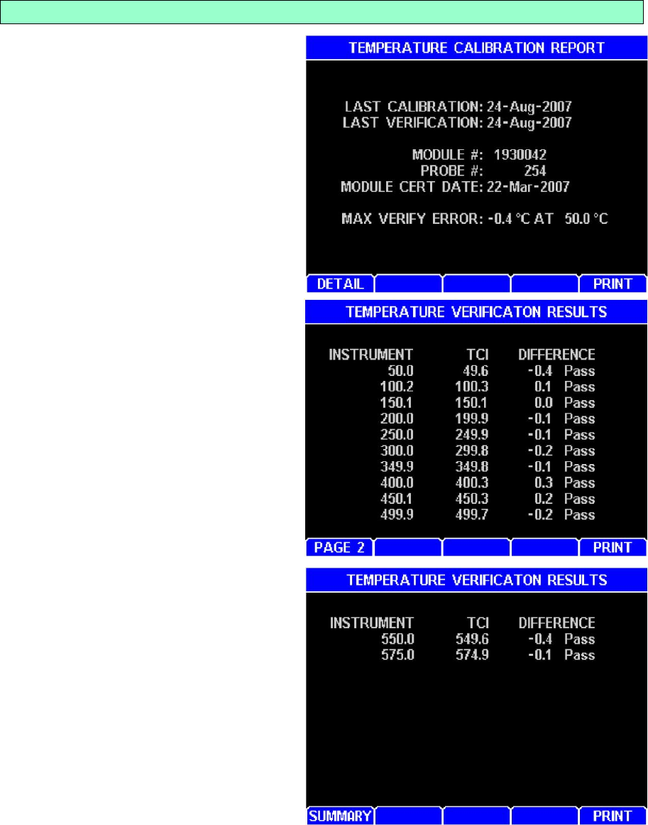
AZI Customer Service 800-528-7411 or 602-470-1414 Page 45 of 92
View Cal Report
The VIEW CAL REPORT selection
provides information about the last
calibration date and performance. A
record of the calibration date,
verification date, and calibration
devices used is shown. The data may
be printed from this screen by pressing
[PRINT].
Pressing [DETAIL] gives a listing of the
calibration temperatures and their
verification results between 50º C and
575º C degrees. See page 43 for
information on how set up the
temperature verification.
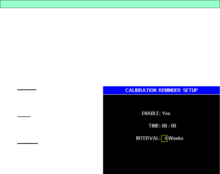
AZI Customer Service 800-528-7411 or 602-470-1414 Page 46 of 92
Calibration Reminder Setup
A TEMPERATURE CALIBRATION REMINDER is available to remind you when
scheduled calibrations are due. The default factory settings are:
ENABLE - No
TIME – 00:00
INTERVAL - 0 Weeks
To turn the prompt on, off, or adjust the interval, go to the Main Test Screen and
select in order: MENU, CALIBRATION MENU, TEMPERATURE CALIBRATION,
and CALIBRATION REMINDER SETUP.
Enable – Toggle to YES to
enable the prompt or NO to
prevent the prompt from
appearing.
Time – The time the prompt is
to appear, usually the start of
the shift (using a 24 hour
format).
Interval – The interval between
calibrations (in weeks). If the
interval is set to “00”, the
reminder will occur daily.
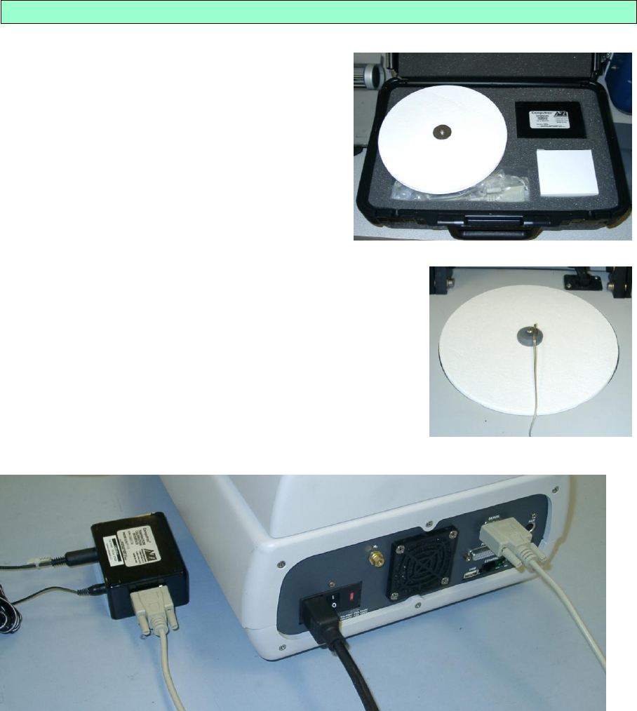
AZI Customer Service 800-528-7411 or 602-470-1414 Page 47 of 92
Temperature Calibration Instructions
Ensure the instrument is turned ON
A Temperature Calibration Kit, [AZI P/N
Y990-0193 for 110V or Y990-0224 for
220V], with 9 VDC, 100 mA, 3.5 mm
male plug positive tip adaptor, must be
used to perform the calibration.
A graphics capable printer may be
connected to the MAX 5000XL if a
printed report is required.
Gently remove the pan support and ceramic balance cover.
Install the temperature calibration fixture so the probe
mount and wires are as shown and gently close the
lid.
Plug the disk interface cable into the matching
connector on the TCI module box. Plug the serial
interface cable into the matching connector on the
TCI module box and the serial port on the back of the
unit. Plug the 9VDC adaptor into the TCI module box
and an appropriate AC outlet.
From the Main Test Screen select in order; MENU, CALIBRATION MENU,
TEMPERATURE CALIBRATION
Highlight CALIBRATION MODULE SETUP and press [ENT]. Enter the
appropriate data for the TCI module serial number, probe serial number and
calibration/certification date.
The interface serial number and certification date are located on the TCI box
label.
AZI Customer Service 800-528-7411 or 602-470-1414 Page 48 of 92
The disk number is located on the probe fixture and should match the probe
number on the TCI box. If the probe number does not match the serial number
on the TCI box, call customer service at 800-528-7411 or 602-470-1414 for
assistance.
Return to the TEMPERATURE CALIBRATION MENU; highlight VERIFICATION
SETUP and press the [ENT] key.
Select AUTO VERIFY AFTER CAL: YES to automatically run the verification
after the calibration is complete and the instrument has cooled down.
If NO is selected, a verification may be performed manually later if desired.
To verify the twelve (12) factory points between 50C to 575C, ensure that
POINTS TO VERIFY is set to “ALL CAL POINTS”
To verify up to four (4) custom points, set POINTS TO VERIFY to 1, 2, 3, or 4.
Set CUSTOM TEMPERATURE VERIFICATION POINTS to the desired
temperatures up to 575º C. Factory defaults are 100, 150, 200, and 250. The
entries are saved if there are no highlights on the display.
NOTE: The remaining instructions assume that verification is being run
automatically.
Return to the TEMPERATURE CALIBRATION MENU; highlight PERFORM
CALIBRATION and press the [ENT] key.
A screen prompt appears to ensure that you have the temperature calibration
device connected. If the device is hooked up, press [GO].
NOTE: Temperature calibration and verification is a lengthy process that
requires about 6 hours to complete; consider performing the calibration at
night. Once begun, do not open the lid during the calibration or verification
process. Although the cool down process may be speeded up by opening
the lid between calibration and verification, disturbing the oven may cause
verification errors. One way to save time is to start the calibration when
the instrument’s oven is below 40º C. The instrument must adjust the
temperature to and be stable at 40º C for several minutes before
beginning the calibration.
When the verification is complete, the screen will display:
The verification temperatures, and,
The pass or fail condition at each calibration temperature.
To print out the calibration report, highlight VIEW CAL REPORT and press [ENT].
Press [PRINT].
Calibration is complete.
Open the lid and wait for it to cool.
Turn off the instrument, disconnect the TCI, and remove the temperature
calibration disk fixture. Carefully reinstall the ceramic balance cover and pan
support.
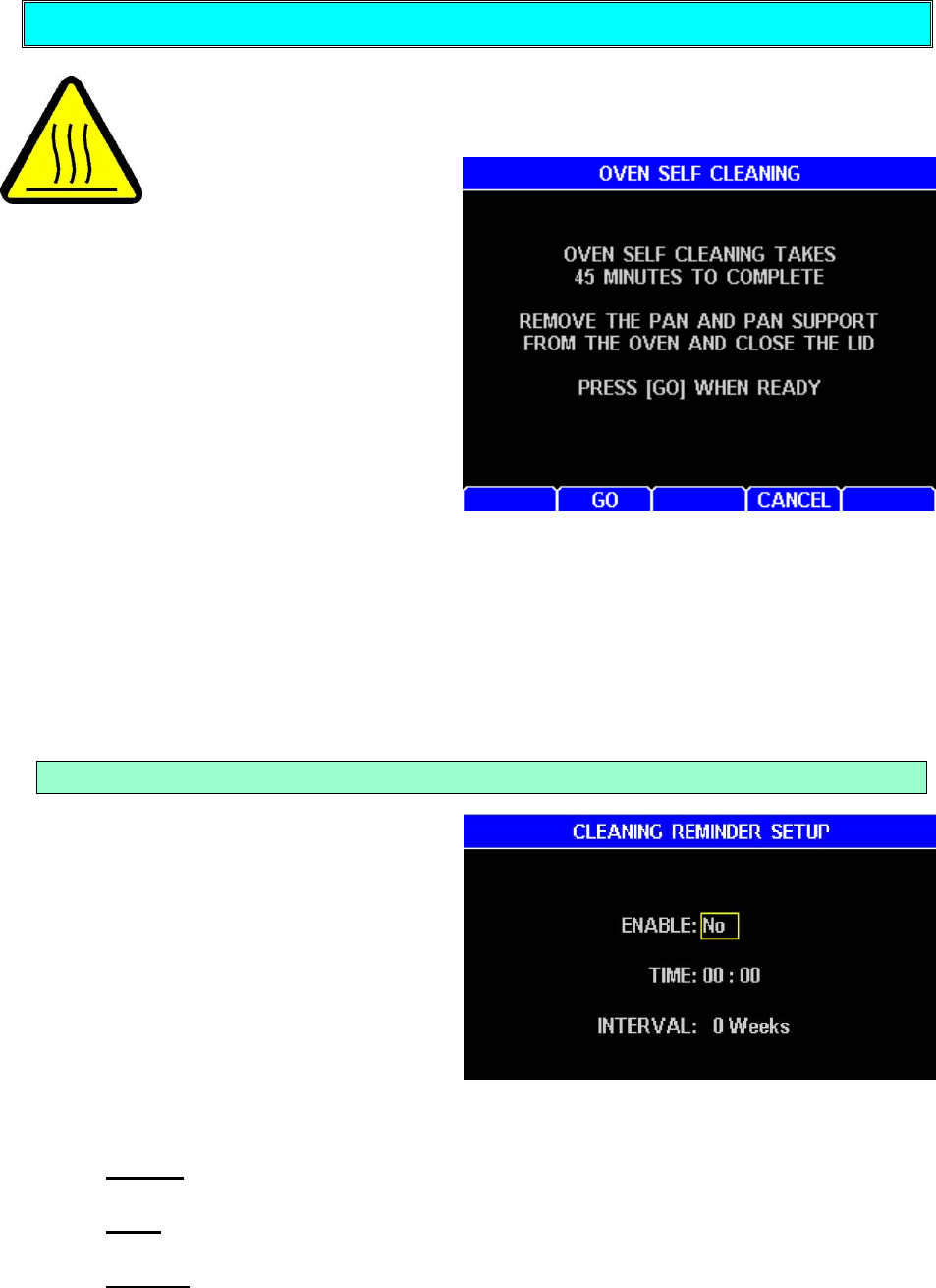
AZI Customer Service 800-528-7411 or 602-470-1414 Page 49 of 92
Oven Cleaning
This selection is the start of an oven cleaning process that burns off most
residue build-up in the oven. Use a fume hood to remove possible toxic
emissions from the
work place. Similar to
the self-cleaning mode
in a home oven, the process turns the
heating elements on to reach an oven
temperature of 550º C in less than 22
minutes. The oven temperature will be
maintained for a total oven cleaning
time of 45 minutes from start to finish.
The heat generated makes the top of
the instrument hotter than normal.
Extreme caution should be used to
prevent injury until the instrument has
cooled down at the conclusion of the
cleaning cycle. During the cleaning cycle, there may be smoke, odor, and possible
toxic emissions produced by the instrument. This is normal as the residue is burned
off the oven lining. Use a fume hood to remove the fumes and smoke from the work
place. Consult the MSDS on your sample materials to determine the content of the
emissions.
For a complete description of the oven cleaning procedure, see section beginning on
page 80.
Cleaning Reminder Setup
A CLEANING REMINDER is available
to remind you to clean the oven
regularly. The default factory settings
are:
ENABLE - No
TIME – 00:00
INTERVAL - 0 Weeks
To turn the prompt on or off, or
adjust the interval, go to the Main
Test Screen and select in order: MENU, CALIBRATION MENU, OVEN SELF
CLEANING, and CLEANING REMINDER SETUP.
Enable – Toggle to YES to enable the prompt or NO to prevent the prompt from
appearing.
Time – The time the prompt is to appear, usually the start of the shift (using a
24 hour format).
Interval – The interval between calibrations (in weeks). If the interval is set to
“00”, the reminder will occur daily.
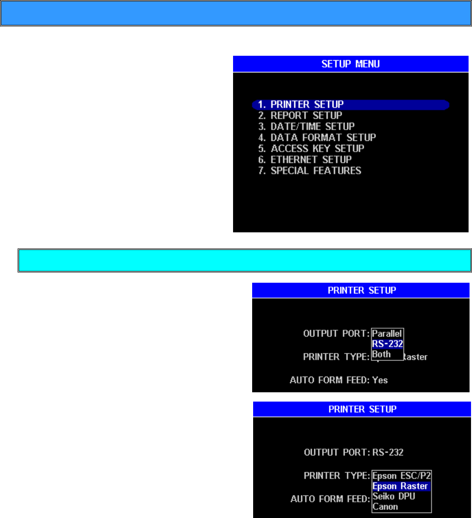
AZI Customer Service 800-528-7411 or 602-470-1414 Page 50 of 92
5.4. Setup Menu
The SETUP MENU is used to program the MAX 5000XL with information relevant to all
operations and tests.
From the SETUP MENU, it is possible to
setup the printer, items to be printed, time
and date, certain items on the display,
access codes, network addressing and
access, and prepare foils for testing.
Printer Setup
This menu provides a means of selecting
the type of printer that is attached to the
MAX 5000XL, which port is to be used,
and if an automatic form feed is desired. If
the port option of “Both” is selected the
data will be sent to the computer serial
port and the parallel printer port. Graphics
will not be sent to the RS-232 serial port.
See “Connecting a Printer” on page 16
and “Connecting a Computer” on page 19.
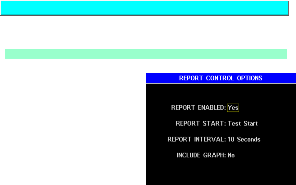
AZI Customer Service 800-528-7411 or 602-470-1414 Page 51 of 92
Report Setup
This menu allows the report outputs to be enabled and the printout to be customized
to your needs.
Report Control Options
REPORT ENABLED – A YES sends a progress report (optional, see below) to the
printer during a test and a final report to
the printer after a test.
REPORT START – These three options
determine if a progress report begins at
the start of the test, when the first
prediction of final result is made, or just a
final report at the end of the test.
REPORT INTERVAL – This selection
determines how often the progress report
data is sent to the printer or computer.
Times of 1, 5, 10, 15, and 30 seconds or
one (1) minute are available. The short
durations are good for trials and research
and the long intervals are good for normal use.
INCLUDE GRAPH – When YES is set, a graph of the results will be sent to the printer
after the final report. Graphic data is not sent to the computer.
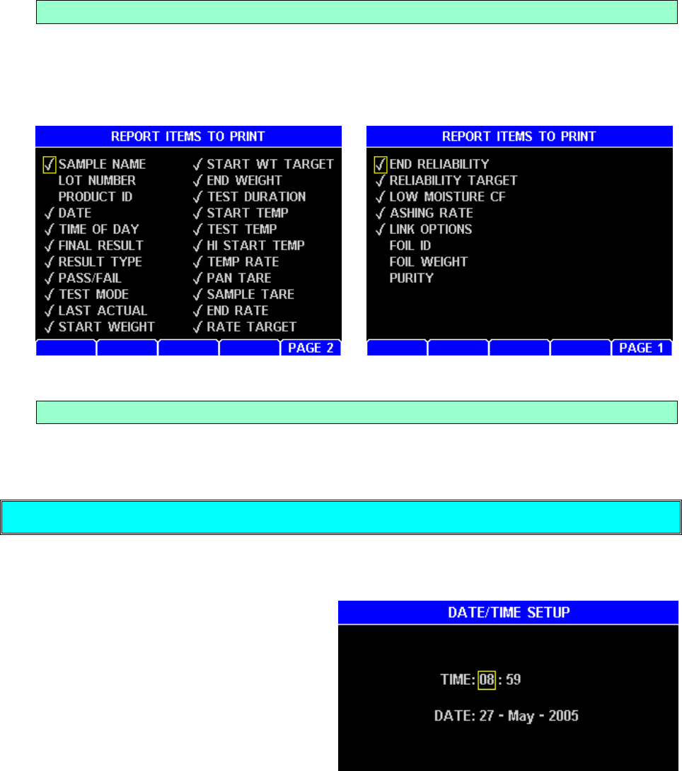
AZI Customer Service 800-528-7411 or 602-470-1414 Page 52 of 92
Report Items to Print
Test results are available to be printed, sent to a computer, or used for statistical
analysis (mean, standard deviation and relative standard deviation). To be printed,
the data fields must be selected. Highlight the data to be printed and press the [ENT]
key. Press [PAGE 2] or [PAGE 1] to switch between pages.
Add/Edit Company Name
This selection provides a means of customizing reports to show the name of the
company, test location, or other alphanumeric identifiers.
Date/Time Setup
This selection is used to enter the correct date and time (24 hour format) into the
instrument’s clock system. The internal battery saves the clock value when the power
is off.
Use this function to change the time at
initial setup or when changing for
daylight savings time
The clock in the MAX 5000XL uses a
small battery to maintain correct time
and date. If the clock resets whenever
the power is off, the internal backup
battery may need to be replaced. If
this happens, call AZI Customer Service at 800-528-7411 or 602-470-1414. A battery
that fails does not affect the memory of the MAX 5000XL since the memory does not
depend on a battery backup during power off conditions.
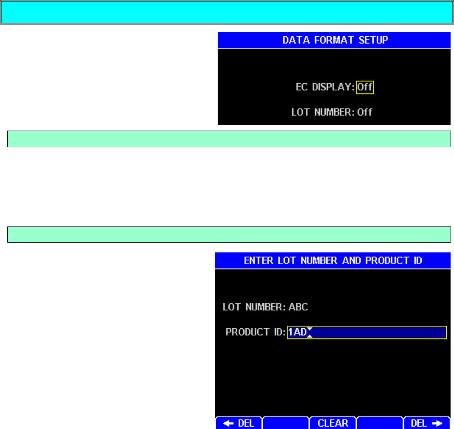
AZI Customer Service 800-528-7411 or 602-470-1414 Page 53 of 92
Data Format Setup
This menu brings up the two categories
of data, one display oriented and the
other report oriented.
EC Display
This selection controls the displaying of the word RELIABILITY on the Main Test
Screen for PREDICT ENDING CRITERIA. Displaying this value is useful during
parameter development to aid in selecting the best ending criteria. It may also help
the operator to determine the remaining test time if the ending criteria target is known.
Lot Number
If the LOT NUMBER function is ON,
starting a material test brings up a
screen labeled ENTER LOT NUMBER
AND PRODUCT ID. These
alphanumeric entries may be used to
insert the lot designation and unique
product identification into reports. Not
all industries or processes will use
them so they may be enabled only
when needed.
LOT NUMBER: – Alphanumeric code
to identify the product lot number.
PRODUCT ID: - Alphanumeric code
used by some companies to identify specific products.
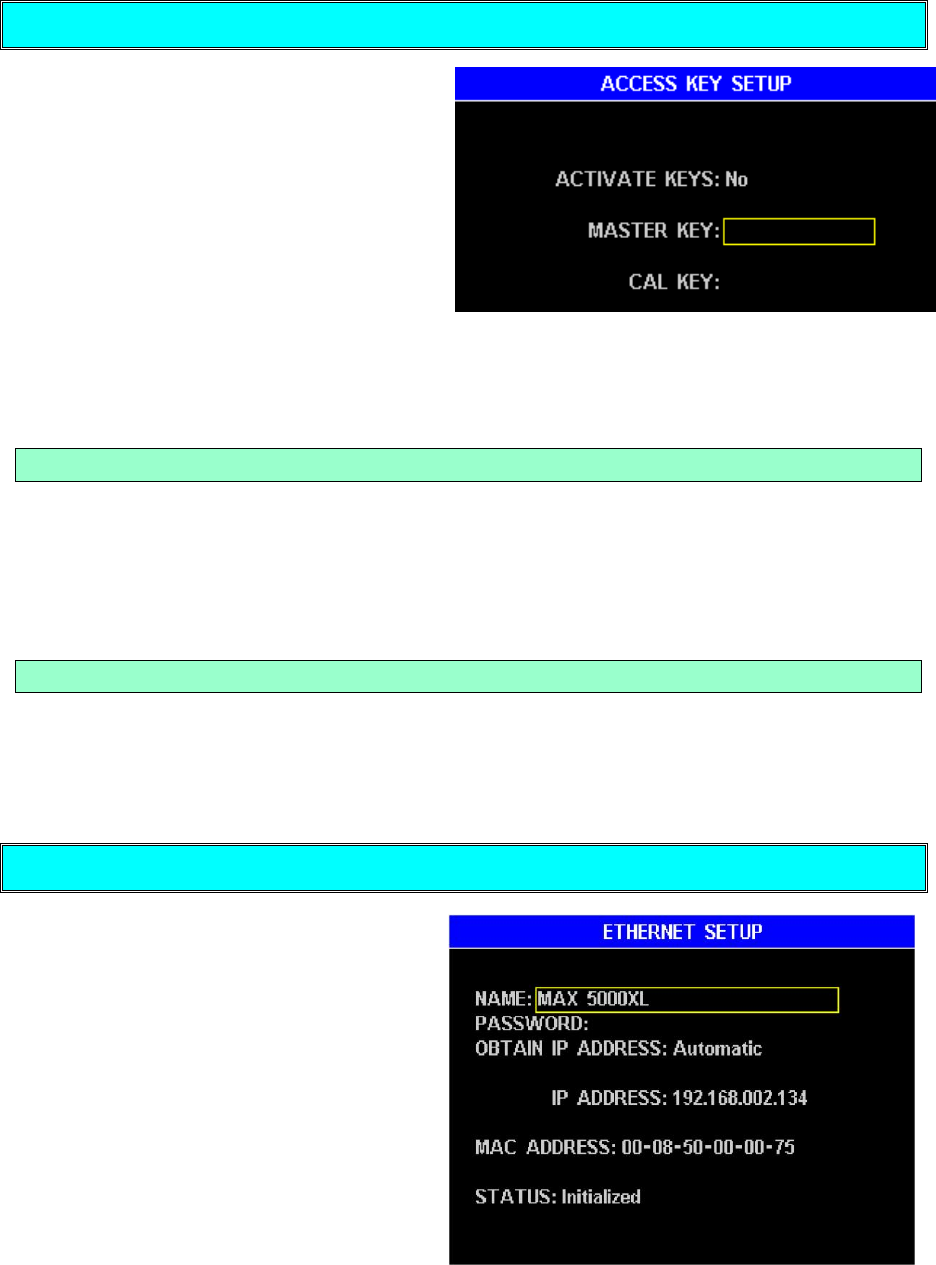
AZI Customer Service 800-528-7411 or 602-470-1414 Page 54 of 92
Access Key Setup
This menu provides a means of
preventing unauthorized access to
memory start edit, calibration, and
setup menus. If Access Keys have
been activated by setting Activate
Keys: Yes, and a Master Key code has
been entered, the instrument will
prompt for the key code each time a
protected menu is accessed. If a key
code is present, setting Activate Keys:
No will provide temporary access to menus without having to enter any codes, and
then the existing code or codes can be easily re-activated by setting Activate Keys:
Yes.
Master Key
The master key code permits access to all menus protected by the access keys
(memory start edit, calibration, and setup menus). But access to calibration menus is
not restricted by an active master key unless a calibration key is also active. If the
master key code is lost, call AZI Customer Service at 800-528-7411 or
602-470-1414.
Calibration Key
If the memory start edit and setup menus have been protected by activating Access
Keys and entering a Master Key, an optional calibration key code restricts access to
the calibration menus, and therefore also offers selective access to the calibration
functions only.
Ethernet Setup
A Web Server option can be purchased
for the MAX 5000XL, and then the
instrument can be accessed from your
local area network (LAN) or intranet by
a PC. The Ethernet Setup menu
provides the necessary controls and
options to configure this connection.
Generally, the MAX 5000XL cannot be
viewed on the Internet because of
company firewalls, but it is possible and
requires a registered IP address.
See the Web Server section on page 75
for full details on the Web Server.
Call AZI customer service for more information and purchasing questions.
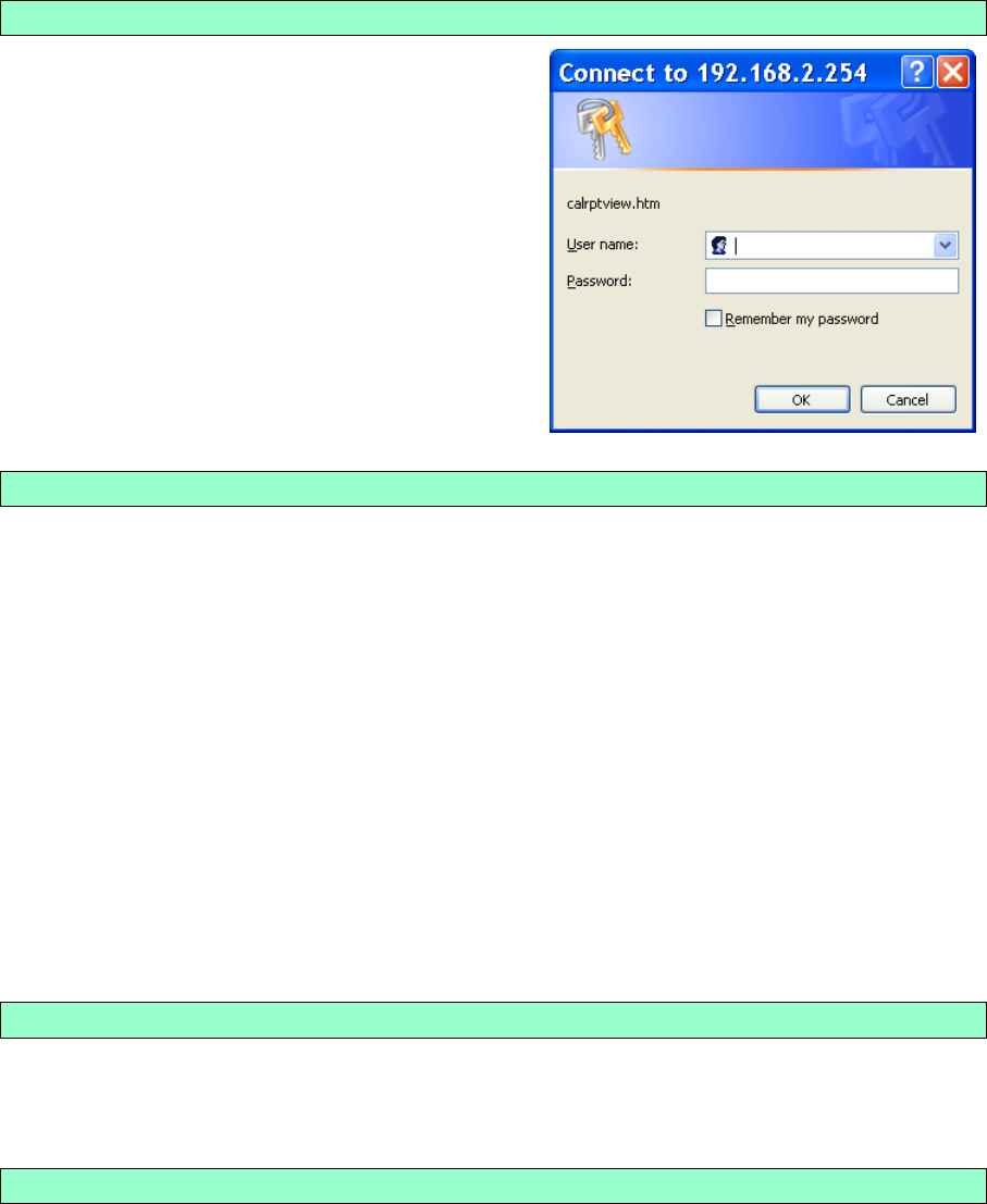
AZI Customer Service 800-528-7411 or 602-470-1414 Page 55 of 92
Although the following options are accessible in all MAX 5000XL instruments, the
optional Web Server feature must be purchased in order to access the instrument over
your network.
NAME and PASSWORD
The NAME and PASSWORD can be used to
restrict access to the instrument over the
intranet. When using IE enter NAME for the
User name and enter PASSWORD for the
Password to gain access to the instrument.
OBTAIN IP ADDRESS
This can be set to Automatic, Manual, or Ethernet Off.
Automatic - Sets everything automatically. A DHCP server is required to obtain
the IP address. Because the IP address is not known until the DHCP server
assigns it, intranet users will have to be given the IP address whenever the
instrument powers up, which is undesirable. Manual mode is typically used
because the IP address is fixed. Automatic mode is useful to see if the Web Server
works, and then the user should switch to manual mode.
Manual – Requires the manual entry of IP Address, Subnet Mask, and Gateway.
Consult with your IS department for the correct settings.
WARNING: DO NOT SET THE IP ADDRESS TO THE SERVER OR GATEWAY
IP ADDRESS. Doing so can cause the network to crash.
Ethernet Off – Disables the Ethernet port.
MAC ADDRESS
The MAC address is factory set and is unique to every Internet device. It may be
helpful to your Information Services (IS) department.
STATUS
This displays the Ethernet status. If everything is setup correctly, then the Status
should turn to “Initialized” shortly after power up. Otherwise, an error will be reported.
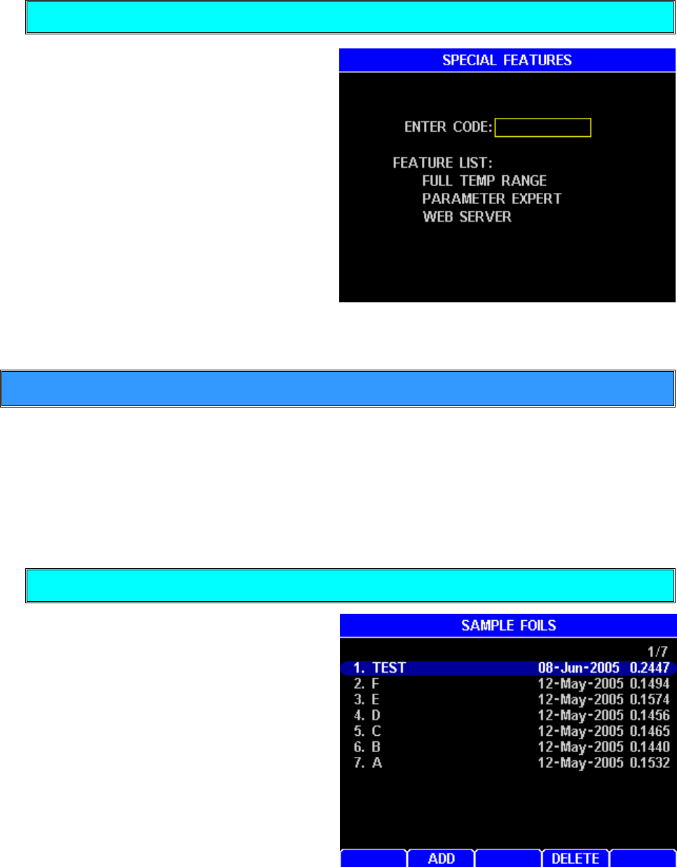
AZI Customer Service 800-528-7411 or 602-470-1414 Page 56 of 92
Special Features
This menu provides optional features
for the instrument. A Web Server and
Parameter development tools are
examples of additional features that
can be purchased. If you have
purchased one of these features, you
have been given an access code to
enable/disable the feature. Entering
the code will toggle the feature on/off.
For more information regarding the
special features available on your MAX
5000XL, please call your technical
sales representative or AZI Customer
Service at 800-528-7411 or
602-470-1414.
5.5. Sample Foils
Selecting this option from the Main Menu will begin the process of weighing and storing
the weights of 50 foils. The foils are used in paint processes where the paint is sprayed
onto the foil as the end product is being painted. When placed into the MAX 5000XL, the
weight of the foil will be subtracted from both the start weight and ending weight so that
only the spray product will be considered in the moisture determination. Pan tare will first
tare the empty sample pan, see pg. 30.
Enter Foils
From Main Menu, select Sample
Foils. Select [ADD] or [DELETE] to
add or delete a foil.
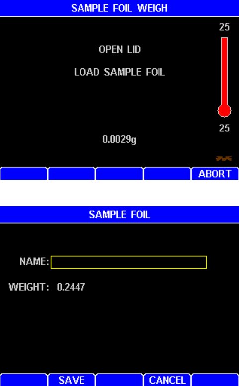
AZI Customer Service 800-528-7411 or 602-470-1414 Page 57 of 92
To add a new foil, select [ADD].
Follow the prompts to open the lid,
place a foil on the sample pan, and
close the lid.
After the foil is weighed and the lid
is opened, the weight of the foil is
given and a box appears so that a
unique identifying name may be
given to the foil.
Save the weight and ID so they will
be available during sample test.
Press [SAVE] to save the
information or [CANCEL] to return
to the SAMPLE FOIL menu.
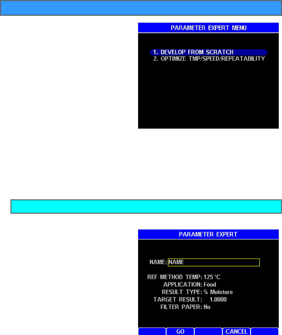
AZI Customer Service 800-528-7411 or 602-470-1414 Page 58 of 92
5.6. Parameter Expert (Optional Feature)
A Parameter Expert option can be
purchased for the MAX 5000XL. The
Parameter Expert (PE) assists a user
through the development of a memory
start. PE queries the user about his
reference method, sets up a memory
start, and walks the user through a series
of tests to determine the highest
acceptable test temperature. To speed
development, tests are stopped if it looks
like they will not end in a reasonable time;
a higher test temperature will be tried
instead. In the end, PE programs the
memory start, which produces a fast and
accurate test. PE works on most samples up to 300°C. For ashing, PE sets up a memory
start and runs a single test to determine the proper ending rate (if possible). Ashing may
require more complex parameter development. Typical PE development time is < 2
hours for products < 25% moisture.
PE can be exited and reentered, and PE remembers the previous tests, so development
will continue were it was previously stopped.
Develop From Scratch
The Parameter Expert is informative and guides the user through the steps.
NAME – This is used for the new
memory start name.
REF METHOD TEMP – Enter the
temperature used by the reference
method. If temp > 300, then PE
assumes ashing mode and sets up
a memory start and runs a single
test to determine the proper
ending rate (if possible).
APPLICATION – Enter the
application type, i.e. food, plastics,
etc.
RESULT TYPE – Enter the result
type output.
TARGET RESULT – Enter the reference method result.
FILTER PAPER – Liquids and creams may require filter paper to produce
repeatable results. Because filter paper is expensive, try developing with “No” filter
paper first.
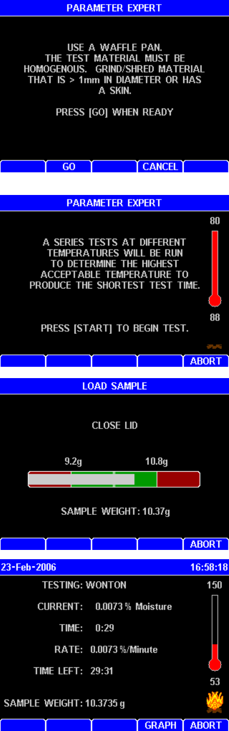
AZI Customer Service 800-528-7411 or 602-470-1414 Page 59 of 92
• This is an interim screen. Ensure you have
the material properly prepared.
•This is another interim screen. You will see
these throughout the Parameter Expert
testing. Continue to press start to go to next
step in the parameter development process
•Add sample to pan until white bar is within
green area. Instrument will beep indicating the
proper weight. Close lid.
•The test will complete, and additional
instructions will come to the screen.
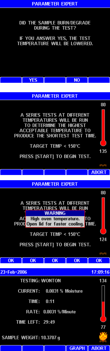
AZI Customer Service 800-528-7411 or 602-470-1414 Page 60 of 92
• Answer appropriately and the system will ask
you to start the next test.
• In this example, the answer was YES. In this
case, the parameterization will be done at a
lower temperature. Press start to begin the
next test.
•The display will recommend opening the lid if
the oven temperature is too high. Open the lid
and press OK.
• Once the temperature in the chamber is
correct, press Start. The system will lead you
through the next test.
•Note the test temperature is lowered from 150
to 134 deg C.
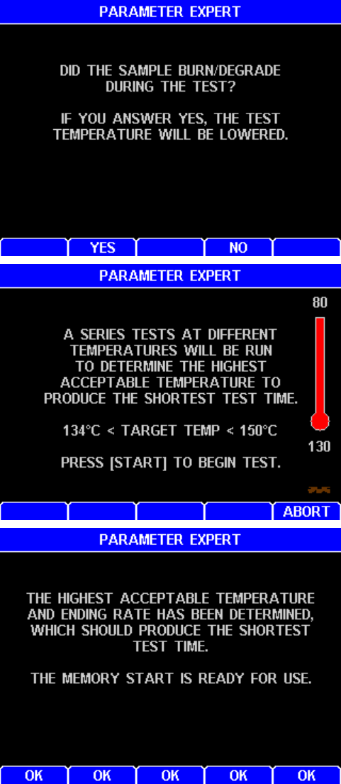
AZI Customer Service 800-528-7411 or 602-470-1414 Page 61 of 92
•Again the system prompts to see if the
temperature is too high, indicated by a
burned or degraded sample. In this case the
answer is NO.
•The system will then lead you to the optimal
temperature for the fastest test time. Press
Start to begin the next test.
•The system will continue through the
iterative optimization process until the
optimal temperature is achieved in the
shortest amount of test time without
degrading or burning the sample. A memory
start will be created. Press OK.
•If the iterative process goes through 5 times
without completing, it would be best to restart
the Parameter Expert, as the initial
temperature was significantly incorrect. This
may also occur for materials that tend to burn
or degrade easily.
•Once the memory start has been developed, exit the Parameter Expert screen and
run 5 tests to determine if the accuracy, speed, and repeatability are acceptable. Use
the Optimize feature to make minor improvements.
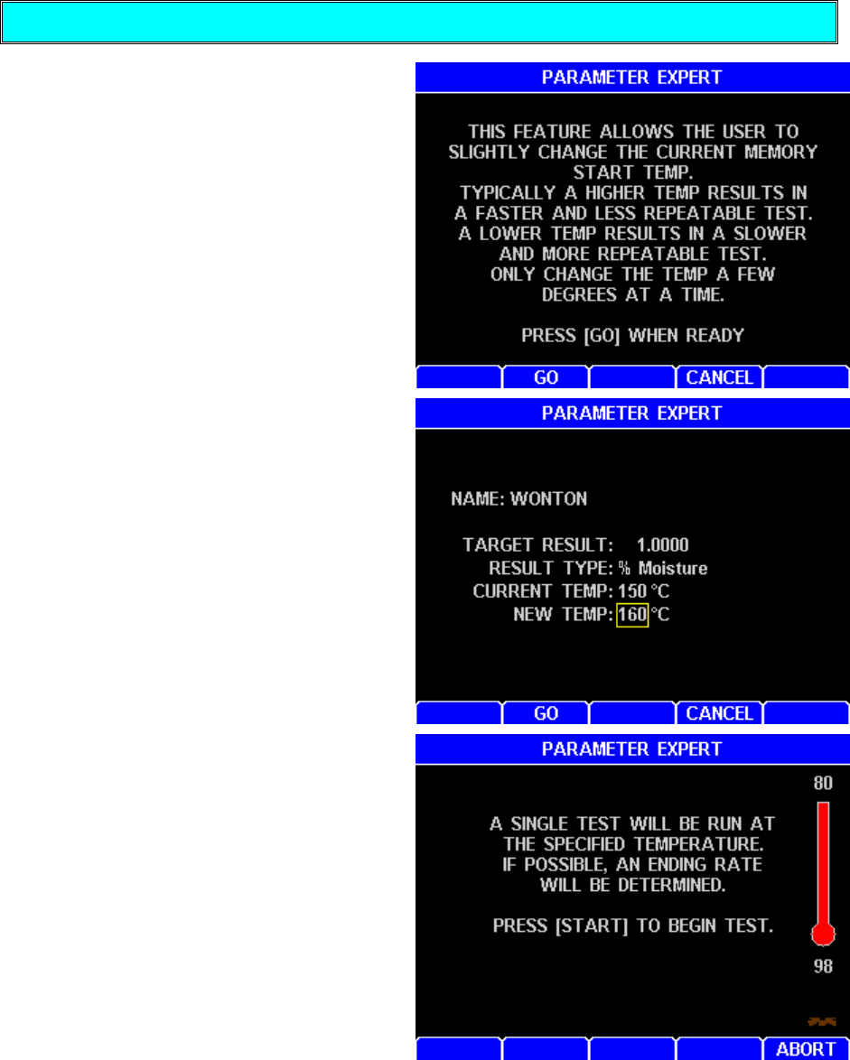
AZI Customer Service 800-528-7411 or 602-470-1414 Page 62 of 92
Optimize Temp/Speed/Repeatability
The Parameter Expert Optimize feature
determines the proper ending rate
criteria for a user-specified test
temperature for the currently active
memory start. The Optimize feature is
for an already developed memory start
that needs minor improvement. The
Optimize feature allows the user to raise
or lower the test temperature to improve
test speed and repeatability. Typically,
a higher temperature results in a faster
and less repeatable test. A lower
temperature results in a slower and more
repeatable test.
•Raise the temperature to speed up the
test. Press GO.
•Have the sample prepared and ready
to start the optimization test. Press
Start.
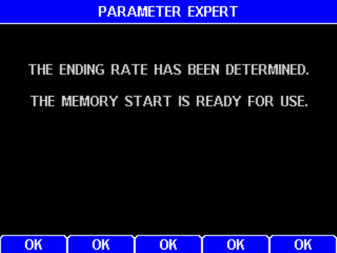
AZI Customer Service 800-528-7411 or 602-470-1414 Page 63 of 92
•Optimization is complete and the memory
start has been modified. Press OK and exit
Parameter Expert to use the optimized
memory start.
For more information regarding the Parameter Expert option, please contact Arizona
Instrument Sales or a customer service representative at 800-528-7411 or
602-470-1414.
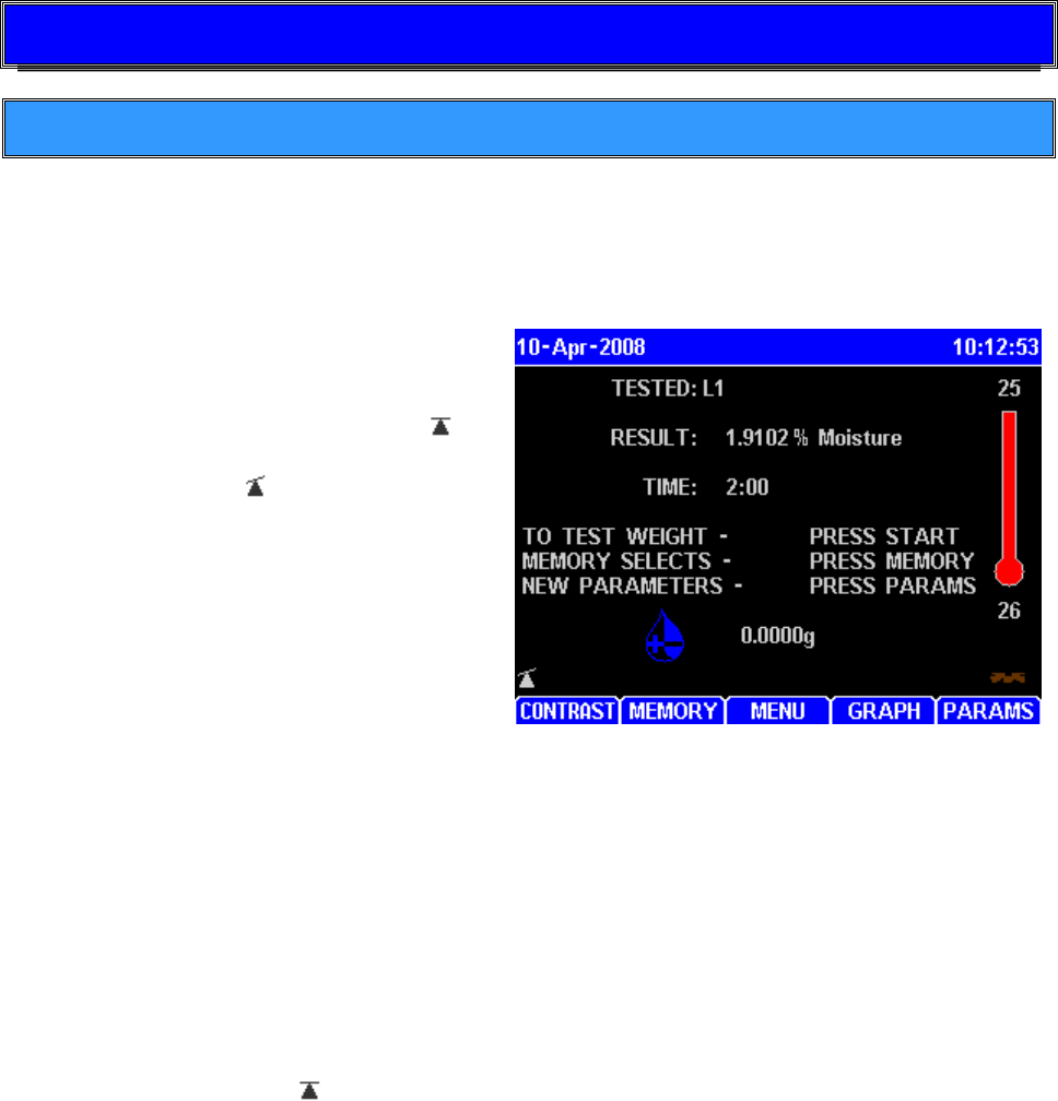
AZI Customer Service 800-528-7411 or 602-470-1414 Page 64 of 92
6. SAMPLE PREPARATION, TESTING AND ANALYSIS
6.1. Balance Temperature Stability
The force balance in the MAX 5000XL is most accurate in a stable temperature
environment. To maintain a constant balance temperature, whether the instrument is
testing or idling, the instrument heats the balance at initial power-up and maintains the
balance temperature at all times.
The balance temperature stability icon is
in the lower left corner of the LCD when
viewing the main screen. It is a triangle
with a line on top. A horizontal line
indicates that the balance is temperature
stable. A tilted line (as shown in the
picture) indicates that the balance
temperature is changing.
Upon first power up, the instrument may
take 2 hours to stabilize the balance at an
elevated temperature. If the instrument is
toggled off and back on, the new balance
warmup period may be 20 minutes to 1
hour. All Computrac Moisture Analyzers are recommended to be left turned on when not
in use, so the balance warmup should not affect throughput after the initial stabilization
period.
The first ashing test after a power up may increase the balance temperature slightly, and
the warmup message may be displayed again for up to 1 hour after the first test. The
message generally goes away while the instrument is cooling down and before it is ready
for the next test.
Generally, balance calibration and low moisture/solids/ash testing (<1%) should be
delayed until the balance temperature stabilization is complete, as indicated by the
temperature stable icon .

AZI Customer Service 800-528-7411 or 602-470-1414 Page 65 of 92
6.2. Preparing Granular and Powdery Samples
The MAX 5000XL can be used to test a wide range of products from finely ground,
low-moisture powders to high-moisture slurries. For best results, the sample should
be of a uniform particle size distributed evenly over the sample pan. If sample
material is collected into a jar or sampling bag, shake the jar or bag to produce a uniform
mixture. Liquid samples should also be mixed or shaken to ensure a more homogeneous
mixture. Large chunk samples, such as charcoal or cookies, should be crushed or ground
to smaller pieces approximately 1/4" or less in diameter. For best results, take care not
to over-grind the sample, causing it to heat up and causing moisture loss.
Some samples, such as dried vegetables, may also need to be ground. The smaller
pieces will easily release moisture during testing, leading to shorter test times and more
repeatable results. Solid, granular sample material should be shaken onto the pan from
a spoon; shaking sample directly from the collection jar will usually deposit only the larger
granules, not a representative mixture. Liquid samples or slurries can be spooned or
poured onto the sample pan; however, a pipette or sampling straw will collect a uniform
mixture of the sample. All samples should be evenly distributed over the sample pan.
6.3. Preparing and Testing Liquid Samples
Some liquid samples will dry slowly, even at high temperatures. Drops or puddles may
form on the pan and dry slowly as the sample concentrates. A skin may form which limits
evaporation from the interior. Long test times (greater than 25 minutes) and low percent
moisture (or high percent solids values) suggest incomplete drying. Pre-dried glass-fiber
filter paper and flat-bottomed pans are recommended to successfully test samples such
as these.
The glass-fiber filter paper, AZI P/N 990-0003, serves as a support for the liquid sample.
The sample is absorbed through the paper for more even and rapid evaporation to
reduce test times. Waffle-bottomed sample pans are not recommended for use with filter
paper. The liquid sample may soak through the filter paper and collect in puddles in the
pan's depressions. Flat-bottom pans are available from AZI as P/N 990-0010. Call AZI
parts sales at 800-528-7411 or 602-470-1414 to order.
Occasionally, some samples cannot be absorbed into the filter paper. At the end of the
test, examination of the sample pan shows the sample sitting high above the filter paper
with a thick crust. The crust may be singed from the heat or even show bubbling where
vapor has been trapped beneath the surface. %SOLIDS results will be high or
%MOISTURE results will be low. Samples such as these are treated differently: After the
sample has been added to the sample pan, remove the pan from the test chamber and
place it onto a flat surface. Grasp part of the filter paper (tweezers are suggested) and flip
it over so that the sample lies between the pan and the paper. Squash the sample with
a flat-bottom glass or jar to a uniform layer. Return the sample pan to the test chamber
and close the lid. The upper filter paper surface absorbs moisture from the sample and
minimizes bubbling and spattering to produce more accurate, reproducible results.

AZI Customer Service 800-528-7411 or 602-470-1414 Page 66 of 92
6.4. Selecting the Optimum Sample Size
Each particular sample will have its own optimum sample size. Best results will be
obtained if the sample consists of a single layer of particles, as long as this is sufficient to
develop a weight loss of 10 milligrams or more. A rule of thumb is "the lower the moisture,
the larger the sample." Low-moisture samples, less than 0.10%, such as chemicals or
plastics, require larger amounts; the instrument is optimized to run low moisture samples
with a 30g load. The larger sample size is necessary to provide sufficient weight-loss
information to the microprocessor. A larger weight change between the initial and final
sample weights will give more accurate, repeatable results. A smaller sample size will
give faster tests. Generally, it is best to use a thin layer that just covers the surface of the
pan. Very light, or very expensive, test materials may necessitate weighing as little as
150 milligrams. Be aware that the standard error will be larger for samples this small,
unless the moisture content is sufficient to cause a weight change of 10 milligrams or
more for each test. If the first result is too low, increase sample size or raise the
temperature. If it is too high, decrease sample size, or lower the temperature.
The sample should be added evenly, in a thin layer, across the entire surface of the pan.
Once the desired amount has been added, the pan can be removed from the test
chamber to evenly distribute the sample. The sample should be distributed over the
surface by gentle shaking, tapping, or for very viscous samples, spread with a spoon or
knife. Do not spread granular products with a spoon as the particles compress even
under gentle pressure affecting test times and results. An even layer of sample across
the pan will reduce test times and increase precision of results.
7. PERFORMANCE ENHANCEMENT
7.1. Introduction
Please note: The information presented here is general in nature.
The Computrac MAX Series loss-on-drying moisture analysis system takes advantage of
computer technology to reduce test times and increase precision over standard vacuum
oven or convection oven drying procedures. The sample is added to an aluminum
sample pan sitting atop an electronic force balance within a test chamber. As the sample
heats and loses weight due to moisture evaporation, the balance records that weight loss
and transmits the data to the microprocessor. The microprocessor interprets the
information and compares the sample's weight loss to a standard drying curve. The final
moisture concentration is extrapolated from the curve and results are available within
minutes.
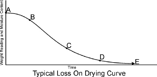
AZI Customer Service 800-528-7411 or 602-470-1414 Page 67 of 92
A typical drying curve is shown at the
right.
Section (A-B) represents the sample's
weight loss as it heats from room to
testing temperature.
Section (B-C) is linear, representing
moisture loss from the interior of each
particle of the tested sample.
Section (C-D) is exponential in nature
and represents the final evolution of moisture from within the particle. The point at which
no additional weight loss occurs represents the complete evolution of water from the
original sample (E).
Section (D-E) is the longest and most time-consuming portion of the entire testing
process. The time for a sample to reach zero residual moisture in an oven can take from
one to possibly 24 hours depending upon the sample, sample preparation, and testing
temperature. The MAX 5000XL loss-on-drying system calculates the sample's moisture
concentration through mathematical extrapolation from the exponential (C-D) portion of
the curve.
An aluminum pan sits on a pan support coupled to a sensitive electronic force balance.
The force balance registers the initial weight of the sample before testing and relays the
sample's decreasing weight to the microprocessor for evaluation. Balance readings are
averaged to eliminate signal interference or erroneous data.
Within each memory start, test temperatures can be programmed between normal room
temperature (25º C) and 600º C in either a one-step or multi-step temperature contour.
A heater is located on the underside of the test chamber's lid. An RTD monitors the
temperature of the test chamber and sends that information back to the microprocessor.
Under the microprocessor's control, the heater element is cycled on and off to bring the
test chamber to the programmed level.
During the entire testing process, the microprocessor monitors the sample's weight loss.
The sample's decreasing weight is compared to the initial sample weight and the
calculated moisture concentration will appear on the display. Simultaneously, the
microprocessor is predicting a final moisture concentration based upon the sample's rate
of weight loss compared to the exponential portion of a standard drying curve. Testing
will continue until the predicted moisture concentration agrees within a certain percentage
of the actual moisture concentration appearing on the display. The percent agreement
between the predicted and the actual moisture concentrations will vary depending upon
the system's programming and the moisture level of the sample.
The MAX 5000XL is an extremely flexible instrument. This flexibility means that some
time is required to determine the best set of parameters for a particular application. The
determination of the proper parameters requires a series of tests, and good laboratory
procedure. Call your AZI technical sales representative at 800-528-7411 or
602-470-1414 for assistance.
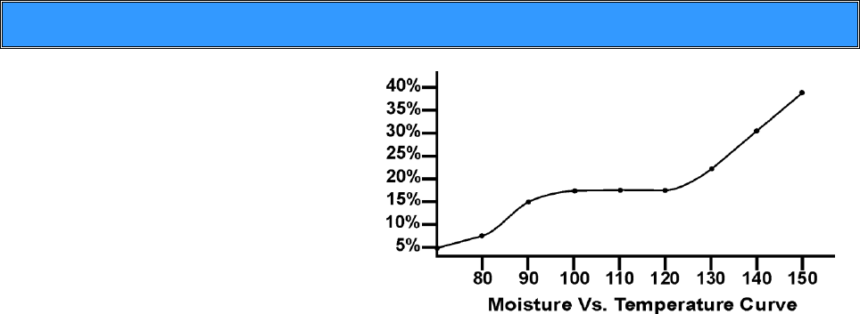
AZI Customer Service 800-528-7411 or 602-470-1414 Page 68 of 92
7.2. Determining Proper Test Temperature
If the moisture of the sample material
is known, as determined by a
reference method, the MAX 5000XL's
temperature can be adjusted until test
results correlate with the established
moisture concentration. If the
moisture is not known, prepare a
moisture versus temperature curve to
decide the proper test temperature for
a particular sample.
An appropriate curve can be prepared by testing sample material at increasing
temperatures of five-degree increments.
The starting temperature is usually the standard or reference method temperature for that
particular sample. Results for each increasing temperature will usually rise to a plateau
where several temperature increases do not change the results significantly. Beyond this
plateau, results can rise dramatically. Examination of a sample, tested at these increased
temperatures, may show burning or charring.
Results along the plateau usually correlate well with the standard or reference method
results. Repeated testing should be done at temperatures in this range. Several tests are
performed using the same sample size and test parameters. Results from these repeated
tests are tabulated to calculate the mean, or average, and the standard deviation (S.D.).
Analysis of the mean and standard deviation, and their comparison with reference
method results, determines if the proper test temperature has been used. If mean values
do not compare well, or if the standard deviation is too large, test at another temperature
along the plateau.

AZI Customer Service 800-528-7411 or 602-470-1414 Page 69 of 92
7.3. Selection of Ending Criteria
The decision of which ending criteria to use is application dependent. Best results are
typically given with PREDICTION or RATE, rather than TIME. Experiment with your
particular sample to determine which criterion is best for your product. See Ending
Criteria on page 26.
For PREDICTION, the MAX 5000XL uses a sample dependent test to automatically end
a test. The test, called the reliability criterion, is equal to the "actual moisture loss" at a
given moment divided by the end point predicted by the microprocessor times 100. The
ending ratio can be set to a value from 00 to 99 depending on the user's desire to balance
speed and accuracy. The smaller the number, the sooner each test will end. A value of
99 means the actual moisture loss must exceed 99% of the predicted end point.
For RATE, the MAX 5000XL ends the test when the sample weight loss rate has fallen
below a preset percentage value. This is useful for samples that do not conform to the
standard exponential drying model but will show a consistent moisture rate loss at some
point in the process. The parameter may be set for values from 0.0010% to 9.9999% loss
rate.
For TIME, the MAX 5000XL ends the test after a preset time of up to 120 minutes has
past. This is sometimes useful for diagnostic and research purposes.
Use “TEMP THEN …” to prevent a test from ending before the test temperature has been
obtained. This can be helpful for ashing, which takes a while to reach the final
temperature, and for testing ultra low moisture samples, which don’t readily release
moisture at the beginning of the test.

AZI Customer Service 800-528-7411 or 602-470-1414 Page 70 of 92
8. PERFORMANCE VERIFICATION
Periodic checks of the system are recommended to verify proper system operation.
These periodic checks will satisfy some quality assurance requirements as specified in
your quality assurance/control policy. A log is recommended, either hand written or
computer managed, which will record the weight test results, sodium tartrate test results,
and retained samples’ results. Shifts in results that are out of range can be quickly
detected and the appropriate corrections made.
For maximum accuracy, let the system warm up until the balance is temperature stable
before performing any testing (See section “6.1 Balance Temperature Stability” on page
64).
8.1. The Weight Test
The weight test, as described in the section beginning on page 22, simulates moisture
loss with the removal of one of two known weights. This test may be used as part of your
control verification program:
At the interval established by your quality assurance/control program;
Any time the unit is moved, the power switched off, the instrument is jarred or
bumped; and/or
If there is any concern about the accuracy of the instrument.
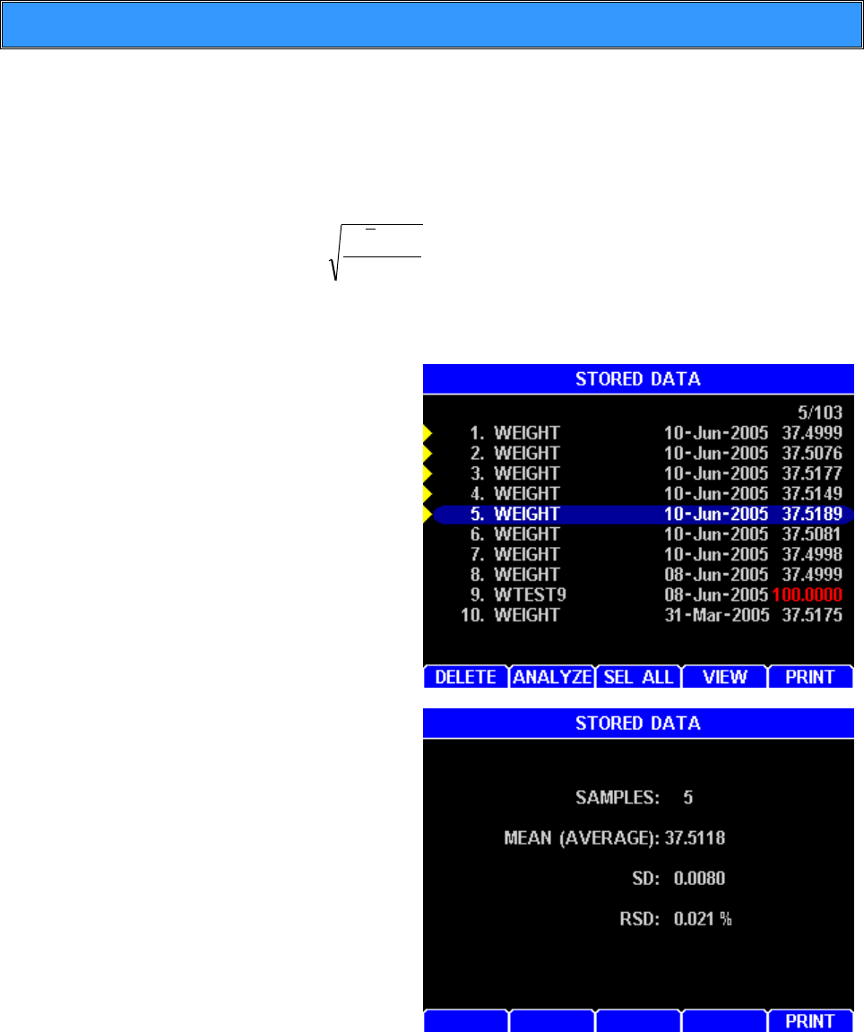
AZI Customer Service 800-528-7411 or 602-470-1414 Page 71 of 92
8.2. The Precision Weight Test
The precision weight test consists of performing the weight test in Section 8.1 multiple
times to determine the instruments repeatability. This is a more critical verification of the
instrument’s performance.
Mean, Standard Deviation, and Relative Standard Deviation are calculated using the
following formulas.
Mean = total of results divided by number of results.
Standard Deviation =
1-n
x-x 2
)(
Relative Standard Deviation expressed as percentage = Standard Deviation
divided by Mean, multiplied by 100
Perform the steps in the weight
test a total of five (5) times.
After all five tests are complete,
press [MENU] and select the
STORED DATA MENU.
PRESS [ENT] to select tests.
Arrow up or down to select the
five weight tests and press
[ANALYZE].
The mean of the results should
be 37.500%, +/-.020 for a test
using the five and three gram
weights.
If the results obtained from these
tests are outside the specified
range, call AZI Customer Service
at 800-528-7411 or 602-470-1414
for assistance.

AZI Customer Service 800-528-7411 or 602-470-1414 Page 72 of 92
8.3. Sodium Tartrate Test
The sodium tartrate test verifies the heater and force balance operation. Sodium tartrate
dihydrate is a chemical with a known moisture concentration that releases moisture at
temperatures greater than 120º C.
Because of its consistent moisture concentration, it is used as a standard in moisture
measurement using oven or titration methods. To obtain consistently reliable results, use
a high quality or reagent grade (ACS certified) granular sodium tartrate. Sift the sodium
tartrate through a #20 sieve to obtain a more uniform size that will achieve better results.
Lumps in sodium tartrate usually indicate moisture absorption that will yield inconsistent
results. Discard the larger chunks, or pestle them through the sieve and return them to
the bottle.
Sodium tartrate is available from AZI as P/N 800-0037. Call AZI part sales at
800-528-7411 or 602-470-1414 for information or to order.
The sodium tartrate test uses approximately 8 grams of sample and is run at 150º C.
Results should be within a range of ±0.1 of the assayed value on the label of the chemical.
Sodium tartrate assayed moistures typically range from 15.61 - 15.71.
Open the lid; place a clean, dry, empty pan the pan
support
Close the lid
From main test screen, press [MEMORY]
Highlight "(Factory) Tartrate" and press [START], then
press [ABORT] (This will set the instrument idle
temperature to 80 degrees.)
Allow the instrument to reach 80°C (Approx. 3-5 minutes)
When the instrument has reach 80°C, press [START]
Allow instrument to tare empty pan
When instructed, open the lid
Add sample; use a spoon to evenly spread 7.9 to 8.1
grams of Tartrate on the surface of the pan (8 grams is
best)
Close the lid and allow instrument to start the test
Allow the test to complete
If this is the first test of the day, discard the results of this test for stability reasons.
Results should be within a range of ±0.1 of the assayed value on the bottle label.

AZI Customer Service 800-528-7411 or 602-470-1414 Page 73 of 92
8.4. Precision Sodium Tartrate Test
Perform the sodium tartrate test in Section 8.3 multiple times to determine the instruments
repeatability. This is a more critical verification of the instrument’s performance.
Mean, Standard Deviation, and Relative Standard Deviation are calculated using the
following formulas.
Mean = total of results divided by number of results.
Standard Deviation =
1-n
x-x 2
)(
Relative Standard Deviation expressed as percentage = Standard
Deviation divided by Mean, multiplied by 100.
Perform the steps in the sodium tartrate test a total of five (5) times.
After all five tests are complete, press [MENU] and select the STORED DATA
MENU.
Press [ENT] to select tests.
Arrow up or down to select the five tartrate tests and press [ANALYZE].
The mean of the results should be within ± 0.1 of the value on the bottle label.
If the result is out of tolerance, the most common causes of such errors are bent
or dirty sample pans, or debris that may have fallen into the balance shaft.
Switch the unit OFF.
Remove the pan support and the balance cover.
Carefully clean the instrument. See page 78.
Clean the oven and check the temperature sensor. See page 80.
If a temperature calibration kit (AZI P/N Y990-0193) is available, calibrate the
system. See page 43.
Repeat the tartrate test again, using a clean sample pan for each of the five
samples, and analyze the results.
If the mean is still out of tolerance, call AZI customer service at 800-528-7411 or
602-470-1414 for assistance.

AZI Customer Service 800-528-7411 or 602-470-1414 Page 74 of 92
8.5. Retained Samples
The weight test and the sodium tartrate test are usually sufficient to satisfy industry
guidelines for quality control in moisture measurement. Some additional checks can be
performed using replicate testing of retained samples. Retained samples, when stored
under airtight conditions, should maintain moisture levels for long periods. Routine
testing of these samples should produce the same results day after day. Retained
samples further verify the unit's operation on the customer's own product. If hygroscopic
materials are used, the values can change with time and repeated opening of the
container.
Set the MAX 5000XL to the optimum test temperature for the retained sample or
use the ID number of a test that has been stored in memory.
Place a clean aluminum sample pan onto the pan support in the test chamber.
Close the lid and press [START].
When the “OPEN LID” display appears, GENTLY add the optimum amount of
retained sample evenly across the sample pan.
Close the lid and allow the test to continue.
Record the result in the quality control log.
The results for the retained sample should fall within the established acceptable
range of results for that sample. If results are out of range, repeat the test to verify
results and/or perform standard reference testing to certify the percent moisture
value.
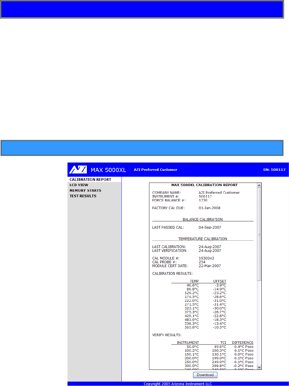
AZI Customer Service 800-528-7411 or 602-470-1414 Page 75 of 92
9. WEB SERVER
An optional Web Server can be purchased for the MAX 5000XL. MS Internet Explorer®
Version 6 or higher (IE) is used to view a calibration report, view the LCD screen,
save/load memory starts, and save test results. Memory starts can be retrieved from one
instrument and saved to another. Test data is saved in a comma delimited format, which
can be read by MS Excel® or a compatible spreadsheet program. To access the
instrument with IE, type the IP address into the IE address field (192.168.2.254 for
example). The IP address is the one that is assigned in the Ethernet Setup section on
page 54.
NOTE: Results data cannot be modified or deleted through the Web Server. Data can
only be deleted at the instrument.
See the Ethernet Setup section on page 54 to setup the Web Server.
9.1. Calibration Report
The calibration
report is viewed by
selecting
CALIBRATION
REPORT in the
left bar. This
report is a
combination of the
balance and
temperature
calibration report.
The report can be
downloaded to
disc as an HTML
file.
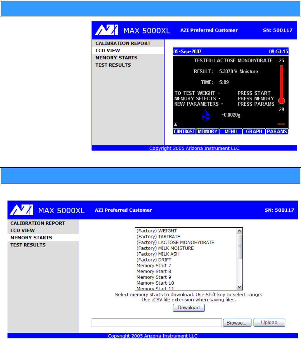
AZI Customer Service 800-528-7411 or 602-470-1414 Page 76 of 92
9.2. LCD View
The LCD screen is
viewed by selecting LCD
VIEW in the left bar.
This may help to
remotely monitor the
instrument.
9.3. Memory Starts
Memory starts can be viewed by selecting MEMORY STARTS in the left bar.
Memory starts can be downloaded from the instrument or can be uploaded to the
instrument. Thus, memory starts can be retrieved from one instrument and saved to
another. Typically, set up one MAX 5000XL with the desired memory starts, transfer the
memory starts to the PC, and then transfer the memory starts from the PC to other
instruments. Memory start data is saved in a comma-delimited format, which can be read
by MS Excel or a compatible spreadsheet program. Although memory starts can be
edited in Excel, it is not recommended.
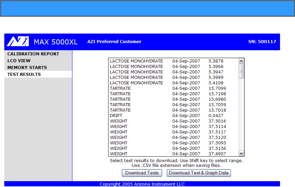
AZI Customer Service 800-528-7411 or 602-470-1414 Page 77 of 92
9.4. Test Results
Test results can be viewed by selecting TEST RESULTS in the left bar.
Test results can be downloaded from the instrument to a PC. Test data is saved in a
comma delimited format, which can be read by MS Excel or a compatible spreadsheet
program. Graph data contains only the data points that are used by the instrument to
generate the graph, so the actual visual graph is not downloaded.
For more information regarding the Web Server option, please contact Arizona Instrument
Sales or customer service representative. 800-528-7411 or 602-470-1414

AZI Customer Service 800-528-7411 or 602-470-1414 Page 78 of 92
10. ROUTINE MAINTENANCE
The MAX 5000XL requires routine cleaning to keep the test chamber free of excess
sample material. Failure to keep the instrument interior clean reduces its accuracy
and repeatability. Sample material collecting in the test chamber prevents free
movement of the pan support. In addition, sample material collecting on the rim of
the heater shroud prevents the lid from closing completely, causing erratic results.
Material may fall into the system's interior, causing balance problems. Routine
cleaning of the test chamber reduces the likelihood of problems and repairs,
extending the life of the instrument.
10.1. Chamber Interior
The chamber interior should be cleaned when needed to eliminate the buildup of sample
material. To clean debris from the chamber’s
interior:
Switch the main power switch OFF.
Use a vacuum line, portable vacuum
cleaner, or a small paintbrush to remove
debris from the area around the balance
cover and pan support stem.
A compressed air line or canned air is not recommended since
debris migrates into the system's interior and settles in the
electronic components and balance stem.
Do not clean the shroud or heater element with a brush, vacuum,
cleaner liquid, or any object. Use the “Oven Chamber Cleaning”
procedure.
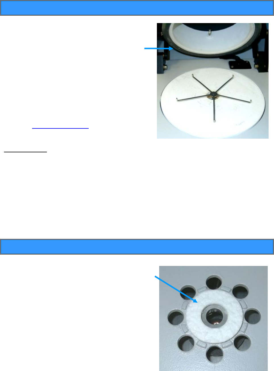
AZI Customer Service 800-528-7411 or 602-470-1414 Page 79 of 92
10.2. Shroud Gasket
The shroud gasket creates a seal between the
heater shroud and ceramic plate. Over time, this
gasket will require replacement.
Check the shroud gasket (AZI P/N 300-0446)
regularly for cracks or deterioration.
Perform a Kimwipe test to verify the seal’s
integrity. (See Kimwipe test below.)
If Kimwipe pulls out easily, then either the shroud
gasket or insulator seal will need replacement.
(See Insulator Seal, Section 10.3 below, for more
information)
If replacement is needed, contact AZI customer
service at 800-528-7411, 602-470-1414, or by
e-mail at support@azic.com for further details
and information.
Kimwipe Test:
Place a Kimwipe, single thickness, on the ceramic insulator plate at the 3 o’clock
position.
Close lid.
Attempt to pull Kimwipe out from between the gasket and plate, being careful not
to rip the Kimwipe.
Repeat at the 6 o’clock and 9 o’clock positions.
o If it removes easily, then either the shroud gasket or insulator seal--or
both--need to be replaced.
o If it does not pull out, then the shroud gasket and insulator seal are o.k.
10.3. Insulator Seal
Beneath the ceramic insulator plate is an insulator
seal that should be checked for compression. The
above Kimwipe test should be performed. If the
Kimwipe is removed easily, then the insulator seal
needs to be replaced. To replace:
Switch the main power switch OFF.
Remove the pan support stem and ceramic
insulator plate.
Replace the worn seal (AZI P/N 250-0001).
Reassemble.
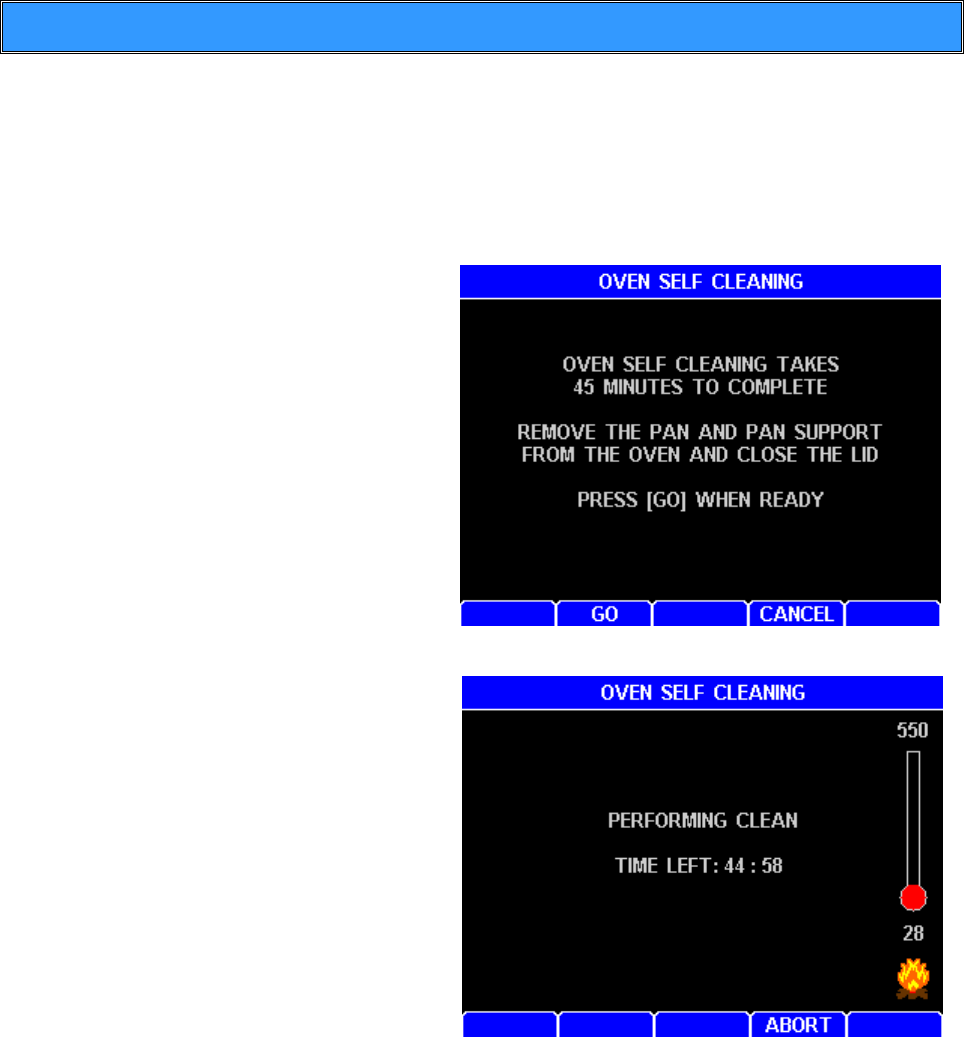
AZI Customer Service 800-528-7411 or 602-470-1414 Page 80 of 92
10.4. Oven Chamber Cleaning
This selection is the start of an oven cleaning process that burns off most residue build up
in the oven. Similar to the self-cleaning mode in a home oven, the process turns the
heating elements on to reach an oven temperature of 550º C in less than 22 minutes. The
oven cleaning cycle lasts a total of 45 minutes. The heat generated makes the top of
the instrument hotter than normal and extreme caution should be used to prevent
injury until the instrument has cooled down after the cleaning cycle.
From the MAIN MENU, select
CALIBRATION MENU and
OVEN SELF CLEANING.
Press [ENT]. The screen display
will provide instructions as
illustrated.
When the pan support has been
gently removed (see page 82),
close the lid and press [GO].
The temperature and time left in
the cleaning process will
displayed
At the conclusion of the cleaning
cycle, the screen will display
“OVEN SELF CLEANING IS DONE.”
Press [OK] or [ESC] to return to
MAIN MENU.
Cleaning frequency will vary depending on the application and frequency of use. We
recommend that you establish a periodic cleaning schedule to ensure unit-to-unit
correlation and performance. Call AZI Customer Service at 800-528-7411 or
602-470-1414 if you have any questions.
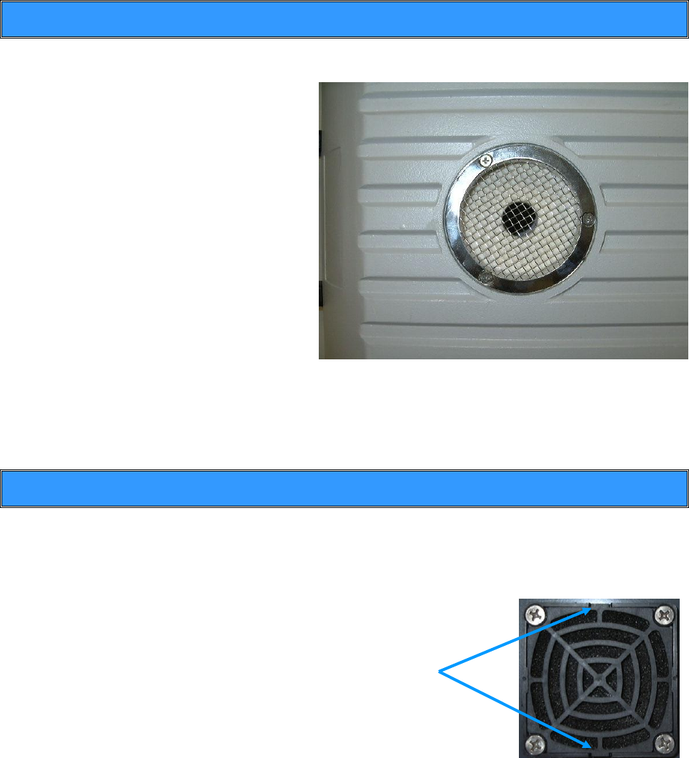
AZI Customer Service 800-528-7411 or 602-470-1414 Page 81 of 92
10.5. Oven Vent Cleaning
The oven vent should be inspected regularly for debris build-up. To clean debris from the
vent:
Switch the main power switch
OFF.
Remove the three (3) screws
securing the vent cover.
Remove the vent cover.
Mechanically remove debris
from the wire screen with a
stiff-bristled brush.
Inspect the vent to ensure that
there is no excessive corrosion.
Corrosion may cause debris
falling back into the instrument,
possibly compromising the
readings and performance of
the instrument.
Replace vent cover if needed (AZI P/N 300-0472).
Reinstall vent cover with the three (3) screws.
10.6. External Filter Cleaning
The optional External Filter Kit (AZI# Y990-0210) has five dust/debris filters that should
be inspected regularly for debris build-up.
To clean debris from the filters:
Switch the main power switch OFF.
Remove shroud at tabs on top
and bottom. See picture at right.
Inspect foam filter for debris build-up.
Clean with compressed air if necessary.
Reinstall shroud by pushing back into
place at tabs with flat side of shroud
against the foam filter.
Repeat for all five filters on the External
Filter Kit.
Tabs

AZI Customer Service 800-528-7411 or 602-470-1414 Page 82 of 92
10.7. Sample Pan Support
The sample pan support may need to be cleaned if high volatile material
condenses on it.
Turn the unit OFF.
Use the supplied tweezers to carefully remove the pan support up out of the test
chamber.
Clean the support post and pan support arms by wiping with a soft cloth or paper
towel.
Carefully reinstall the pan support into the balance stem.
Ensure the arms of the support are all level and about 1/16” to 3/16” from the heat
shield. See page 13 for inspection instructions.
10.8. Lithium Battery Replacement
If the clock fails to keep accurate time when the instrument is turned off for long periods,
the battery on the main control board may be depleted and need to be changed. The
battery is not field replaceable. Contact AZI customer service at 800-528-7411,
602-470-1414, or by e-mail at support@azic.com for further details and information.
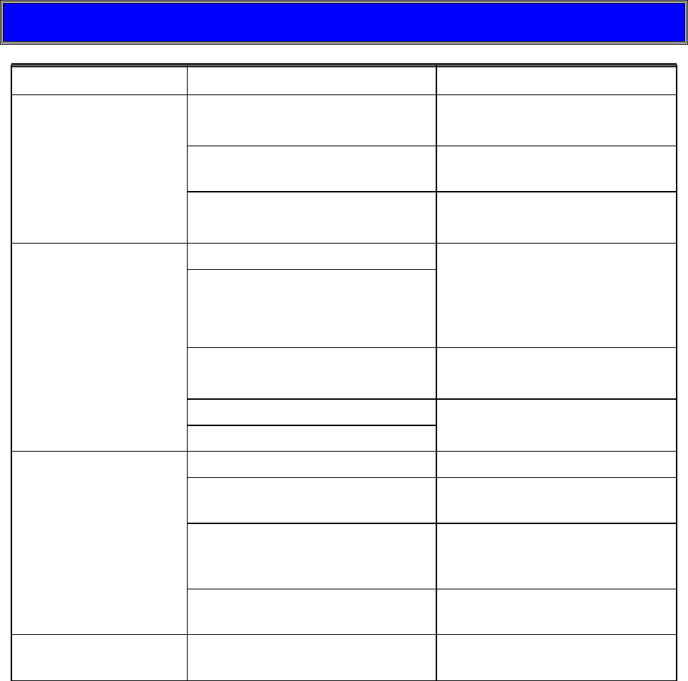
AZI Customer Service 800-528-7411 or 602-470-1414 Page 83 of 92
11. TROUBLE DIAGNOSIS
SYMPTOM
DIAGNOSIS
REMEDY
Final result is always
zero or near zero
Temperature too low
Raise temperature,
see pages 25 & 68
No heat
See No Heat symptom later in
table
Sample too small
Increase sample size,
see pages 29 & 66
Final results vary too
much
Test temperature incorrect
Determine
temperature/ending criteria to
use or call AZI at
800-528-7411 or
602-470-1414 for assistance
Ending criteria incorrect
Sample size too small
Increase sample size,
see pages 29 & 66
Samples not uniform
Grind sample,
see page 65
Sample particles too large
Blank display or very
hard to see
Contrast controls not set
Adjust contrast, see page 16
No power
Check power cord
connections, see page 14
Microprocessor failure
Turn unit OFF and back ON.
Call AZI at 800-528-7411 or
602-470-1414 for assistance
Backlight connector
disconnected
Call AZI at 800-528-7411 or
602-470-1414 for assistance
Heat will not turn off
Circuit board failure
Call AZI at 800-528-7411 or
602-470-1414 for assistance

AZI Customer Service 800-528-7411 or 602-470-1414 Page 84 of 92
Moistures too high or
solids too low
Temperature set too high
Lower temperature,
see pages 25 & 68
Bent sample pan
Use new pan
Dirty sample pan
Use new pan
Debris in balance gaps
Call AZI at 800-528-7411 or
602-470-1414 for assistance
Dirty heater assembly
Clean heater assembly,
see page 80
Ending criteria incorrect
Determine new ending
criteria, see page 26
Call AZI at 800-528-7411 or
602-470-1414 for assistance
Moistures too low or
solids too high
Temperature too low
Increase temperature,
see pages 25 & 68
Sample size too small or too
large
Adjust sample size,
see pages 29 & 66
Sample needs spreading
Spread sample evenly,
see page 65
Ending criteria incorrect
Determine new ending
criteria, see page 26
Call AZI at 800-528-7411 or
602-470-1414 for assistance
Moisture never stops
increasing
Other volatiles
Try lower temperature,
see pages 29 & 66
Balance drifting
Call AZI at 800-528-7411 or
602-470-1414 for assistance
No graphical display
Graphics not selected
Press [GRAPH] key at Main
Test Screen
No heat
Voltage selection wrong
Check power module at rear
of instrument, set to correct
voltage. See page 14
Wiring failure in heater circuit
Call AZI at 800-528-7411 or
602-470-1414 for assistance
Heater failure
Call AZI at 800-528-7411 or
602-470-1414 for assistance

AZI Customer Service 800-528-7411 or 602-470-1414 Page 85 of 92
No heat (cont.)
Door sensor failure
Check display for LID OPEN
message when open during a
test, call AZI at 800-528-7411
or 602-470-1414 for
assistance
Temperature setpoint too low
Raise temperature above
room ambient or standby
temperature, see pages 25 &
68
No power to
instrument
Power switch off
Check switch position,
confirm power cord seating,
remove and test fuse, see
page 14, test the outlet with a
lamp or meter.
Power cord disconnected
Fuse blown
Outlet not powered
No weight reading
Balance not initialized
Turn power off, wait 5
seconds, then turn power on,
wait 15 seconds. Call AZI at
800-528-7411 or
602-470-1414 for assistance
Erratic results
Poor AC ground
Ensure instrument is
grounded from case ground
to earth ground, Call AZI at
800-528-7411 or
602-470-1414
Dirt in chamber
Clean unit,
see pages 78 to 82
Dirt in pan support
See page 78 or call AZI at
800-528-7411 or
602-470-1414 for assistance
Display erratic
Unit cold (near freezing)
Allow to warm-up
THE BALANCE
REPORTS
UNDERLOAD…
Unit powered ON without pan
support in place.
Power off instrument; Install
pan support and power on
instrument, see page 13
UNDER appears on
display when
[START] is pressed
Pan support has been
removed since instrument was
powered ON
Power off instrument; Install
pan support and power on
instrument, see page 13
Instrument won't tare
Test chamber temperature
fluctuates/changes
Allow system to stabilize.
Check tare options,
see page 30
Dirt in test chamber or under
pan support
Clean instrument, see page
78 to 82 and following
AZI Customer Service 800-528-7411 or 602-470-1414 Page 86 of 92
12. ACCESSORIES & MAINTENANCE PARTS
CONSUMABLES
800-0037
Sodium Tartrate (500 gram bottle)
800-0067
Ultrapure Water (1L)
800-0068
Clear Polypropylene
990-0003
Filter Paper (100 PCS)
990-0008
Waffle Bottom Sample Pans (100 PCS)
990-0010
Flat Bottom Sample Pans (100 PCS)
990-0196
Thick Sample Pan (5 PCS)
SPARE PARTS
170-0014
Fan
190-1001
8 Amp Fuse
200-0002
200-0003
200-0008
Power Cord – 110V
Power Cord – 220V UK
Power Cord – 220V Europe
250-0001
Insulator Seal
300-0470
Pan Support Assembly
300-0472
Screen, Vent Cover
690-0003
3g Weight
690-0004
5g Weight
690-0025
50g Weight
690-0012
Tweezers
700-0113
MAX 5000XL User's Manual
Y990-0158
MAX 5000XL Accessory Kit
OPTIONS
Y990-0193
Temperature Calibration Interface Kit with Adaptor (9 VDC output,
100ma, 3.5mm male plug, positive tip) (input is 110V)
Y990-0224
Temperature Calibration Interface Kit with Adaptor (9 VDC output,
100ma, 3.5mm male plug, positive tip) (input is 220V)
6000-1044
Null MODEM Cable
Y990-0098
Printer Kit, Parallel, 110 V
980-0011
Vibration Table
Y990-0197
Parameter Expert
Y990-0210
External Filter Kit
Y990-0221
IQOQPQ Validation Package
Y990-0222
Web Server

AZI Customer Service 800-528-7411 or 602-470-1414 Page 87 of 92
13. MAX 5000XL SPECIFICATIONS
Feature
Specification
Size
18.5” length x 12.7”width x 9.5” height
470 mm length x 323 mm width x 240 mm height
(Height varies slightly with adjustable feet for leveling purposes.)
Weight
31 lbs. (14 kg)
Casework
Textured aluminum castings
Power Requirements
100-130 VAC, 50/60 Hz @ 8 Amps
220-240 VAC, 50/60 Hz @ 4 Amps
Fused on/off switch as part of an EMI power entry module
Operating
Environment
0-35º C @ 50% humidity
0-30º C @ 80% humidity
Non-condensing, non-explosive
Moisture Range
0.1 – 99.9%
Heating Range
25º C to 600º C
Heater Calibration
Menu Driven
NIST Traceable using an accessory Temperature
Calibration Interface module
Calibration tolerance:
± 1.5º C up to 275º C
± 2º C up to 600º C
Twelve calibration points from 50º C to 575º C.
Twelve preset verification points from 50º C to 575º C, or
up to four user-programmable verification points.
Programmable calibration reminder
Temperature Control
± 1º C at temperatures between 50º C and 300º C
± 2º C at temperatures between 301º C and 600º C
Test Temperatures
User programmable through front panel keypad to control
idle temperature, test temperature, and high start
temperature for all tests.
Multiple test temperatures are programmable for linked
test sequences
Heater Chamber
Composite ceramic fiber lined heater chamber
Isolated from electronics to minimize damage from
corrosive sample materials
Oven self cleaning cycle (550º C for 45 minutes)
Balance
Integrated balance with automatic operation
Balance capacity to 100 grams
Resistant to nominal vibration, with options available for
isolation feet
Resistant to air currents from internal exhaust fan
Isolated from extreme temperatures in the test chamber
Isolated from extreme changes in humidity caused by
evaporation in the test chamber

AZI Customer Service 800-528-7411 or 602-470-1414 Page 88 of 92
Balance Calibration
Menu driven calibration and verification in the field
Annual factory servicing recommended
Programmable calibration prompt
Sample size
200 milligrams to 100 grams
Resolution
0.0001 grams
0.001 % moisture
Display
¼ VGA, 320 x 240 pixel color with adjustable contrast via
contrast screen
Test Display
Current and calculated moisture, solids, dry weight, ash, and
loss-on-ignition
Current and programmed chamber temperature
Elapsed test time
Sample name
Rate of weight loss
Electronic Interface
Ethernet – direct connection to internal intranets via
10Base-T connection
Serial Port, 9-pin
Parallel Port, 25-pin
User Interface
User-programmable through keypad
Ethernet connection to internal intranets via 10Base-T
connection
RS-232 Serial Port
Parallel Printer Port
Computer
Communication
Intranet communication and monitoring using a separate
communications package (Web Server)
Applications Software
Menu-driven through keyboard and display
Memory
Storage for:
250 parameter sets,
1,000 test results, and
100 data curves
Statistical Calculation
Mean, standard deviation, relative standard deviation
Access Code
Programmable through front panel
Two codes available for different levels of instrument access
Results Display
% Moisture
% Solids
% Dry Weight
% Ash
% LOI
Linked test results – individual and total results are displayed
after a linked series.
Ending Criteria
Prediction, Rate, Time, Time or Rate, Reliability, Temp then
Predict, Temp then Rate, Temp then Time or Rate
Programmable
Features
Test parameters
Report content
Controlled ashing rate
Temperature ramp rate

AZI Customer Service 800-528-7411 or 602-470-1414 Page 89 of 92
Repeatability
Moisture Level
>10% <5% Relative Standard Deviation
>0.1% <0.1 Standard Deviation
Ashing
>10% ≤5% Relative Standard Deviation
>0.5% ≤0.1 Standard Deviation
Inter-unit Correlation
Moisture Level
>10% ≤5% Relative Standard Deviation
>0.1% ≤0.2 Standard Deviation
Ashing
>0.5% ≤0.10 Standard Deviation
Certification
UL (pending), CE (pending), FCC Part 15, Class A
Tested to standards EN55022, EN 90101-1
Temperature Calibration Interface certified for use with the
MAX 5000XL
Self-diagnostics
Built in Hardware and Software diagnostics software
Options
Temperature calibration interface kit
Printer kit
IQ/OQ/PQ Validation Package
Parameter Expert
Web Server
External Filter Kit
Calibration Weights
Factory calibration weights, Class 1
Field calibration and test weights, Class F
Warranty
Domestic U.S. – 2 years factory parts and labor
International – 1 year

AZI Customer Service 800-528-7411 or 602-470-1414 Page 90 of 92
14. CHANGES
Firmware Rev 3.0X, Manual Rev A
1. Initial release of MAX-5000XL.
a. Added TempRate to memory start record.
b. Added high temperature lift calibration.
c. Added polynomial calculation for high temperature lift compensation to
adjust for different test temperatures.
d. Added a balance temperature stability icon in the lower left corner of the
main screen.

AZI Customer Service 800-528-7411 or 602-470-1414 Page 91 of 92
15. WARRANTY
Arizona Instrument LLC warrants the Computrac MAX 5000XL to be free from defects in
materials or workmanship for two (2) years from the date of purchase for those units sold
in the USA. All other sales normally carry a one (1) year warranty. AZI will repair or
replace, at its option, products that AZI determines to be defective during the warranty
period. All defective parts replaced by AZI become the property of AZI. Replacement
parts are warranted for the remaining portion of the effective warranty period. This
warranty does not apply to expendable or maintenance items such as pans and pan
supports.
The above warranty does not extend to any product which has been subjected to misuse,
abuse, neglect, accident, improper application, modifications or service performed by
persons other than AZI's own service representatives; power surges or spikes;
negligence in use, maintenance, storage, transportation or handling; or acts of God.
If a MAX product is defective in workmanship or materials, the owner's sole remedy shall
be repair or replacement of the defective part, or parts, as provided above. Under no
circumstances shall AZI be liable in any way to the owner or any user for any damage
including, but not limited to, any loss of business or profits or any other direct, indirect,
special incidental, or consequential damages, whether or not foreseeable, and whether
or not based on breach of warranty, contract, or negligence in connection with the sale of
such products. (Some states do not allow the exclusion or limitation of incidental or
consequential damages, so the above limitations or exclusions may not apply to you.)
No other warranty is expressed or implied including the warranties of merchantability or
fitness for a particular purpose. In no event shall AZI be liable for consequential and/or
incidental damages.
The effective warranty begins on the date of purchase by, or lease to, the first end-user
(owner). Keep the dated bill of sale, or invoice, for evidence of the effective warranty date
when warranty service is requested.
In the event that any questions or problems should arise in the use or application of your
Computrac MAX 5000XL unit, call AZI Customer Service or your technical sales
representative at 800-528-7411 or 602-470-1414.

AZI Customer Service 800-528-7411 or 602-470-1414 Page 92 of 92
TRADEMARK AND COPYRIGHT PROTECTION
Computrac, Arizona Instrument and the stylized AZI are all registered trademarks of
Arizona Instrument LLC. MAX 5000XL is a trademark of Arizona Instrument LLC.
Instrument firmware is copyright protected.
The MAX 5000XL uses the Graphics Interchange Format as part of its Ethernet
interface. The Graphics Interchange Format is the Copyright property of CompuServe
Incorporated. GIF(sm) is a Service Mark property of CompuServe Incorporated."
Copyright 2002-2008 Arizona Instrument LLC. All Rights Reserved.
Arizona Instrument LLC
Computrac MAX 5000XL Moisture Analyzer
Manual Part Number: 700-0113
Revision A
April 2008
If you have any questions regarding the operation of this instrument, please call or e-mail
for assistance.
Arizona Instrument LLC
1912 W 4th Street
Tempe, AZ 85281
(800) 528-7411
(602) 470-1414
Fax (480) 804-0656
http://www.azic.com
email:
azi@azic.com - General
intl@azic.com - International
support@azic.com - Customer Support
