Armstrong World Industries Hwc Premier 183 Users Manual TOC
182 to the manual 11ca98e2-2b6c-40ed-8ab5-fac81924aa7b
2015-02-04
: Armstrong-World-Industries Armstrong-World-Industries-Hwc-Premier-183-Users-Manual-362178 armstrong-world-industries-hwc-premier-183-users-manual-362178 armstrong-world-industries pdf
Open the PDF directly: View PDF ![]() .
.
Page Count: 196 [warning: Documents this large are best viewed by clicking the View PDF Link!]
Service Reference Manual
HWC Thru-the-Wall Units
Models:
HWC Premier
122, 182, 242, 302
123, 183, 243, 303
SRM-HW/HWC 8/99
Copyright © 1998
Armstrong Air Conditioning Inc.
All rights reserved.
Disclaimer
This manual presents information and guidelines for proper installation, adjustment, operation
and maintenance of Armstrong Magic-Pak HW/HWC Thru-the-Wall units. Read this manual
before attempting assembly, installation, start-up, adjustment or operation of the unit. If you have
any questions about the operation of the unit or a particular safety device, call or write Arm-
strong Air Conditioning Inc., 421 Monroe Street, Bellevue, Ohio USA 44811. Telephone: 419-
483-4840 Fax: 419-483-3557
The documentation and drawings contained in this manual are intended as a general guide, and
may not reflect exactly the current designs, or all of the options available to our customers.
Please call or write Armstrong Air Conditioning Inc. regarding specific details of a particular
furnace model, configuration or installation.
The information and specifications contained in this manual are subject to change without no-
tice. Armstrong Air Conditioning Inc. reserves the right to change such specifications at any time
without incurring obligation. Every effort has been made to ensure the accuracy of the informa-
tion in this manual. For the most current information, please contact the Armstrong Customer
Service Department.
This document is confidential. All information within is the sole property of Armstrong Air Condi-
tioning Inc. and is loaned for mutual assistance. It may not be used for any purpose other than
originally intended, without prior written consent of Armstrong. It is not intended for use by
homeowners or as a guide for do-it-yourself projects. It provides specialized information for use
by qualified service personnel, who have the proper equipment, training and experience neces-
sary to safely install, repair, adjust and maintain the Magic-Pak units and components described
within.

Service Reference Manual TABLE OF CONTENTS
SRM-HW/HWC 8/99
TABLE OF CONTENTS
1 - Specifications
2 - Sequence of Operations
3 - Unit Tear Down
4 - Component Location Illustrations
5 - Unit Components
6 - Installation
7 - Accessories
8 - Parts Lists
9 - Troubleshooting/Performance/
Charge Weights
Go to: If you need information on:
Section 1 Performance, electrical data and cabinet dimensions.
Section 2 Sequence of operation descriptions with accompanying schematics.
Section 3 Complete description of unit disassembly.
Section 4 Locations of major components of HW/HWC models.
Section 5 Illustrations and specifications for individual components including valves,
blowers, ignition controls and blower control boards.
Section 6 Installation requirements and startup guidelines.
Section 7 Complete listing of all Armstrong accessories available, including wall
sleeves, louvers and gas conversion kits.
Section 8 Complete service parts lists for all HW and HWC models.
Section 9 System check and troubleshooting procedures.

1-1
SRM-HW/HWC 8/99
Service Reference Manual SPECIFICATIONS
Section 1 - Specifications
Models Covered By This Manual ............ 1-2
Model Number Guide ............................ 1-2
Product Serial Numbers
(Beginning 1993) ................................. 1-2
Summary of Model Revisions/Variations 1-3
Heating Configuration Table ........................ 1-3
Cooling Configuration Table ......................... 1-3
HW/HWC ............................................ 1-4
Physical and Electrical ................................ 1-4
Performance Ratings .................................. 1-4
Blower Performance ................................... 1-6
Dimensions ................................................ 1-6
Wall Sleeve................................................ 1-7

1-2
SPECIFICATIONS Magic-Pak: HW/HWC
SRM-HW/HWC 8/99
Models Covered By This Manual
HWC Gas Heating/Electric Cooling Units
HW122, 123
HW182,183
HW242, 243
HW302, 303
HW Gas Heating Only Units
26HW
38HW
51HW
64HW
Model Number Guide
26 = Rated Input BTU/Hr x 1000
H = Gas Heat
W = Thru-the-Wall
C = Cooling
12 = Nominal Cooling BTU/Hr x 1000
2 = Cooling Efficiency 2 - 9.7 SEER
2A = Revision Code
26 H W C 12 2 -- 2A
HW/HWC Models
Product Serial Numbers, Beginning 1993
84 95 A 12345
84 = Armstrong Factory Number
95 = Year (ex: 1995)
A = Month (see list below)
12345 = Sequential Number
A = Jan B = Feb C = Mar D = Apr
E = May F = June G = July H = Aug
J = Sept K = Oct L = Nov M = Dec
1-3
SRM-HW/HWC 8/99
Service Reference Manual SPECIFICATIONS
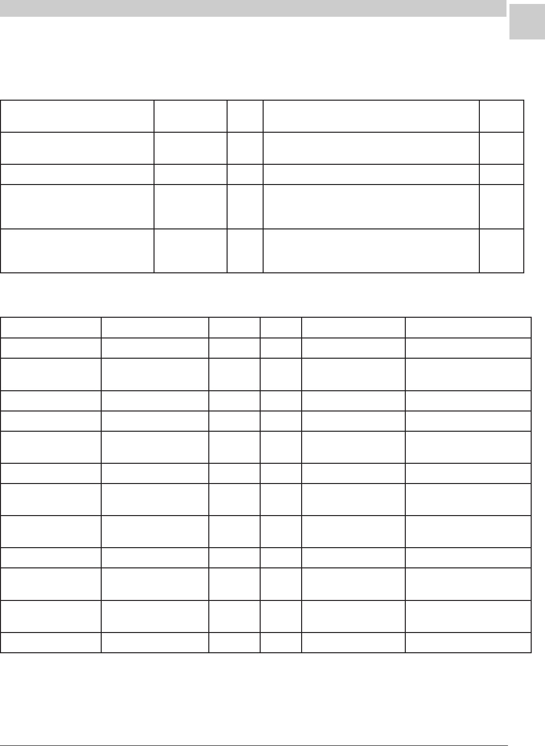
Summary of Model Revisions/Variations
* For more information on the compressors used in HWC units, see the Unit Components section, beginning on page 5-28.
Table 1-1 Heating Configurations of HW/HWC Units
Table 1-2 Cooling Configurations of HWC Units
ledoMnoitarugifnoCEUFAlortnoCrewolB/noitingI noitingI
epyT
1-)303,342,381,321(CWH)llA( /taeHsaG looCcirtcelE 087901lortnoCrewolB/noitingInoitanibmoChceTUISD
9-WH)llA(ylnOtaeHsaG087901lortnoCrewolB/noitingInoitanibmoChceTUISD
)203,242,281,221(CWH)llA( 5-,6-,7-,8-,9-,01-,11- /taeHsaG looCcirtcelE 08 D1642notirTlawneF:lortnoCnoitingI ,104C4HCBItfarctaeH:lortnoCrewolB 0101hceTUro8400B029atledirT ISD
)203,242,281,221(CWH)llA( 1-,2-,3-,4- /taeHsaG looCcirtcelE 08 92-50lawneF:lortnoCnoitingI ,104C4HCBItfarctaeH:lortnoCrewolB 0101hceTUro8400B029atledirT ISD
ledoMnoitarugifnoCegannoTREES*epyTrosserpmoCeciveDgnireteM
1-321CWH)llA(looCcirtcelE/taeHsaG17.9yratoRhesmuceTreirDretliF/ebuTyrallipaC
1-381CWH)llA(looCcirtcelE/taeHsaG5.17.9 hesmuceT gnitacorpiceR reirDretliF/ebuTyrallipaC
1-342CWH)llA(looCcirtcelE/taeHsaG27.9llorcSdnalepoCreirDretliF/ebuTyrallipaC
1-303CWH)llA(looCcirtcelEtaeHsaG5.27.9llorcSdnalepoCreirDretliF/ebuTyrallipaC
-,11-281CWH)llA( 6-,7-,9 looCcirtcelE/taeHsaG5.17.9 hesmuceT gnitacorpiceR reirDretliF/ebuTyrallipaC
9-,11-242CWH)llA(looCcirtcelE/taeHsaG27.9llorcSdnalepoCreirDretliF/ebuTyrallipaC
-,01-221CWH)llA( 1-,3-,4-,5-,8 looCcirtcelE/taeHsaG17.9yratoRhesmuceTreirDretliF/ebuTyrallipaC
-,01-242CWH)llA( 1-,3-,4-,5-,8 looCcirtcelE/taeHsaG27.9llorcSdnalepoCreirDretliF/ebuTyrallipaC
9-203CWH)llA(looCcirtcelE/taeHsaG5.25.9llorcSdnalepoCreirDretliF/ebuTyrallipaC
,5-,8-281CWH)llA( 2-,3-,4- looCcirtcelE/taeHsaG5.17.9yratoRhesmuceTreirDretliF/ebuTyrallipaC
,5-,8-203CWH)llA( 1-,3-,4- looCcirtcelE/taeHsaG5.25.9llorcSdnalepoCreirDretliF/ebuTyrallipaC
1-281CWH)llA(looCcirtcelE/taeHsaG5.15.9llorcSdnalepoCreirDretliF/ebuTyrallipaC
1-4
SPECIFICATIONS Magic-Pak: HW/HWC
SRM-HW/HWC 8/99
Physical and Electrical
HW/HWC
Performance Ratings
Table 1-3 Physical and Electrical Specifications - HWC Units
ledoM /egatloV
esahP/zH
lamroN
egatloV
egnaR
.niM
tiucriC
yticapmA
.xaM
RCAH/esuF
.rkrB
)spma(
.pmoC
detaR
daoL
)spma(
.pmoC
dekcoL
rotoR
)spma(
.D.O
naF
.aiD
).ni(
.moN
MPR
edistuO
naF
detaR
daoL
)spma(
detaR
PH
roodnI
leehW
x.aid
htdiw
).ni(
rewolB
detaR
PH
.girfeR
egrahC
).zo(
thgieW
).sbl(
321/221CWH621/06/032-802352-7913.8510.53.628157019.08/14X016/124523
321/221CWH83 1/06/032-802 352-791 3.8 51 0.5 3.62 81 5701 9.0 8/1 4X01 6/1 24 523
381/281CWH831/06/032-802352-7916.31023.80.548157019.08/14X013/165053
381/281CWH15 1/06/032-802 352-791 6.31 02 3.8 0.54 81 5701 9.0 8/1 4X01 3/1 65 053
381/281CWH461/06/032-802352-7916.31023.80.548157019.08/14X013/165053
342/242CWH63 1/06/032-802 352-791 6.81 52 6.11 5.26 81 5701 8.1 4/1 4X01 3/1 85 063
342/242CWH151/06/032-802352-7916.81526.115.268157018.14/14X013/185063
342/242CWH46 1/06/032-802 352-791 6.81 52 6.11 5.26 81 5701 8.1 4/1 4X01 3/1 85 063
203CWH151/06/032-802352-7914.22036.410.678157018.14/14X013/195083
203CWH46 1/06/032-802 352-791 4.22 03 6.41 0.67 81 5701 8.1 4/1 4X01 3/1 95 083
303CWH151/06/032-802352-7919.12031.410.378157018.14/14X013/195083
303CWH46 1/06/032-802 352-791 9.12 03 1.41 0.37 81 5701 8.1 4/1 4X01 3/1 95 083
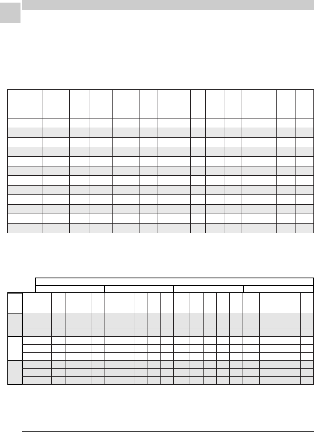
Table 1-4 Performance Ratings - HWC122/123
Note: All values are gross capacities and do not include blower motor heat deduction.
Enter.
Wet
Bulb
63°
67°
71°
Outdoor Air Temperature Entering Outdoor Coil
85° 95° 105° 115°
latoT
riA
.loV
)MFC(
latoT
gnilooC
yticapaC
)hutB(
.pmoC
sttaW
tupnI
taT/S
°57
yrD
bluB
taT/S
°08
yrD
bluB
taT/S
°58
yrD
bluB
latoT
gnilooC
yticapaC
)hutB(
.pmoC
sttaW
tupnI
taT/S
°57
yrD
bluB
taT/S
°08
yrD
bluB
taT/S
°58
yrD
bluB
latoT
gnilooC
yticapaC
)hutB(
.pmoC
sttaW
tupnI
taT/S
°57
yrD
bluB
taT/S
°08
yrD
bluB
taT/S
°58
yrD
bluB
latoT
gnilooC
yticapaC
)hutB(
.pmoC
sttaW
tupnI
taT/S
°57
yrD
bluB
taT/S
°08
yrD
bluB
taT/S
°58
yrD
bluB
0040062102887.29.00.10002101908.59.00.100411000128.59.00.100801090158.00.100.1
0540082102828.79.00.10022101958.00.100.100611000178.00.100.100011090109.00.100.1
0050013102878.00.100.10042101909.00.100.100811000129.00.100.100211090159.00.100.1
0040043102895.47.98.0072101906.67.19.00121010126.97.00.100511011136.18.69.
0540063102826.87.49.0092101946.08.79.00321010156.38.00.100711011176.68.00.1
0050093102856.28.99.0023101976.48.00.100621010196.88.00.100911011107.19.00.1
0040024103804.65.27.0053102904.75.47.00821020114.85.67.00121021114.95.87.
0540044103824.95.67.0073102924.06.87.00031020134.26.08.00321021134.36.28.
0050074103844.26.08.0004102944.36.28.00331020154.56.48.00621021154.66.78.
1-5
SRM-HW/HWC 8/99
Service Reference Manual SPECIFICATIONS
Performance Ratings (continued)
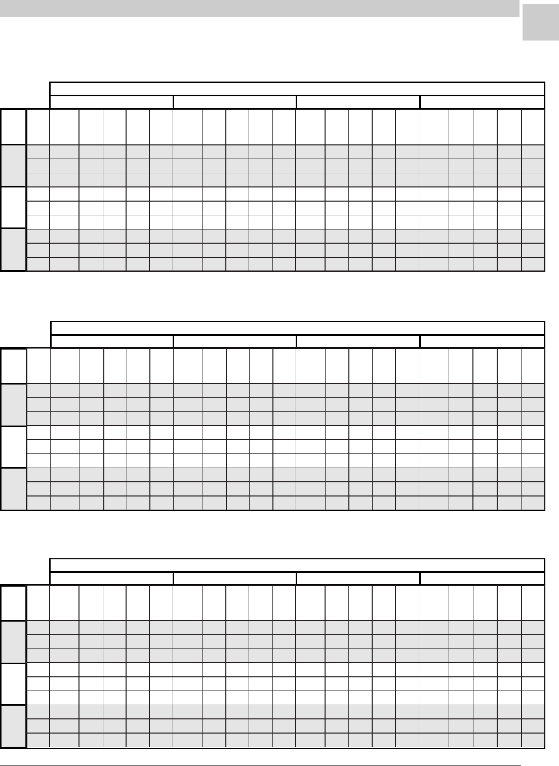
Table 1-5 Performance Ratings - HWC182/183
Table 1-6 Performance Ratings - HWC242/243
Table 1-7 Performance Ratings - HWC302/303
Note: All values are gross capacities and do not include blower motor heat deduction.
Enter.
Wet
Bulb
63°
67°
71°
Outdoor Air Temperature Entering Outdoor Coil
85° 95° 105° 115°
Note: All values are gross capacities and do not include blower motor heat deduction.
Enter.
Wet
Bulb
63°
67°
71°
Outdoor Air Temperature Entering Outdoor Coil
85° 95° 105° 115°
Note: All values are gross capacities and do not include blower motor heat deduction.
Enter.
Wet
Bulb
63°
67°
71°
Outdoor Air Temperature Entering Outdoor Coil
85° 95° 105° 115°
latoT
riA
.loV
)MFC(
latoT
gnilooC
yticapaC
)hutB(
.pmoC
sttaW
tupnI
taT/S
°57
yrD
bluB
taT/S
°08
yrD
bluB
taT/S
°58
yrD
bluB
latoT
gnilooC
yticapaC
)hutB(
.pmoC
sttaW
tupnI
taT/S
°57
yrD
bluB
taT/S
°08
yrD
bluB
taT/S
°58
yrD
bluB
latoT
gnilooC
yticapaC
)hutB(
.pmoC
sttaW
tupnI
taT/S
°57
yrD
bluB
taT/S
°08
yrD
bluB
taT/S
°58
yrD
bluB
latoT
gnilooC
yticapaC
)hutB(
.pmoC
sttaW
tupnI
taT/S
°57
yrD
bluB
taT/S
°08
yrD
bluB
taT/S
°58
yrD
bluB
05500481073157.09.00.100171074187.29.00.100751055128.69.00.100441046168.69.00.1
00600781083187.39.00.100471084118.69.00.100061065158.00.100.100641056198.00.100.1
05600981093118.69.00.100671094148.99.00.100261075188.00.100.100841066129.00.100.1
05500891014185.27.78.00581015195.47.98.00171006126.87.49.00651007146.08.69.
00600102024106.57.09.00881025126.77.39.00471016146.18.89.00951017166.38.00.1
05600402034126.87.39.00091035146.08.69.00671026166.48.00.100161027186.68.00.1
05500212054104.55.96.00791055104.65.27.00381056114.85.57.00761057114.06.87.
00600512064124.75.27.00002065124.95.57.00681066134.16.87.00071067134.26.18.
05600812074134.95.47.00302075134.06.87.00881076144.36.18.00271077144.46.48.
latoT
riA
.loV
)MFC(
latoT
gnilooC
yticapaC
)hutB(
.pmoC
sttaW
tupnI
taT/S
°57
yrD
bluB
taT/S
°08
yrD
bluB
taT/S
°58
yrD
bluB
latoT
gnilooC
yticapaC
)hutB(
.pmoC
sttaW
tupnI
taT/S
°57
yrD
bluB
taT/S
°08
yrD
bluB
taT/S
°58
yrD
bluB
latoT
gnilooC
yticapaC
)hutB(
.pmoC
sttaW
tupnI
taT/S
°57
yrD
bluB
taT/S
°08
yrD
bluB
taT/S
°58
yrD
bluB
latoT
gnilooC
yticapaC
)hutB(
.pmoC
sttaW
tupnI
taT/S
°57
yrD
bluB
taT/S
°08
yrD
bluB
taT/S
°58
yrD
bluB
00700342078147.88.00.100232011267.98.00.100812083287.49.00.100012017208.59.00.1
00800742078187.39.00.100632011208.49.00.100222083228.99.00.100312017248.00.100.1
00900252088128.89.00.100142021258.99.00.100622093278.00.100.100712027298.00.100.1
00700952098175.17.58.00742031285.27.68.00632004295.57.19.00422057206.67.29.
00800362098106.57.09.00152031216.67.19.00042004226.97.69.00822057236.08.79.
00900862009136.97.59.00652041246.08.69.00542014266.48.00.100232067276.58.00.1
00700372019104.55.96.00162051204.55.07.00942034204.65.27.00732077204.75.47.
00800772019124.85.37.00562051224.85.47.00352034224.95.67.00142077224.06.87.
00900382029144.16.77.00072061244.16.87.00852044244.26.08.00642087244.36.28.
latoT
riA
.loV
)MFC(
latoT
gnilooC
yticapaC
)hutB(
.pmoC
sttaW
tupnI
taT/S
°57
yrD
bluB
taT/S
°08
yrD
bluB
taT/S
°58
yrD
bluB
latoT
gnilooC
yticapaC
)hutB(
.pmoC
sttaW
tupnI
taT/S
°57
yrD
bluB
taT/S
°08
yrD
bluB
taT/S
°58
yrD
bluB
latoT
gnilooC
yticapaC
)hutB(
.pmoC
sttaW
tupnI
taT/S
°57
yrD
bluB
taT/S
°08
yrD
bluB
taT/S
°58
yrD
bluB
latoT
gnilooC
yticapaC
)hutB(
.pmoC
sttaW
tupnI
taT/S
°57
yrD
bluB
taT/S
°08
yrD
bluB
taT/S
°58
yrD
bluB
57700582051227.48.79.00372093237.78.00.100162076247.98.00.100842099267.09.00.1
05800982061247.78.00.100672004267.09.00.100462086277.39.00.10015200039739.00.1
52900392071277.09.00.100082014297.39.00.100862096208.69.00.100452010328.69.00.1
57700403091265.96.28.00092044275.17.48.00872027285.37.88.00462050395.37.88.
05800803002285.17.58.00492054295.37.78.00182037206.57.19.00762060316.67.19.
52900213012206.37.78.00892064216.67.09.00582047226.87.49.00172070336.97.49.
57700223022204.45.86.00803084214.55.96.00392067214.65.17.00082090324.75.37.
05800623032214.65.07.00213094224.75.17.00792077224.85.37.00382001334.95.57.
52900033042224.75.27.00613005234.85.37.00103087234.06.67.00782011354.16.87.
1-6
SPECIFICATIONS Magic-Pak: HW/HWC
SRM-HW/HWC 8/99
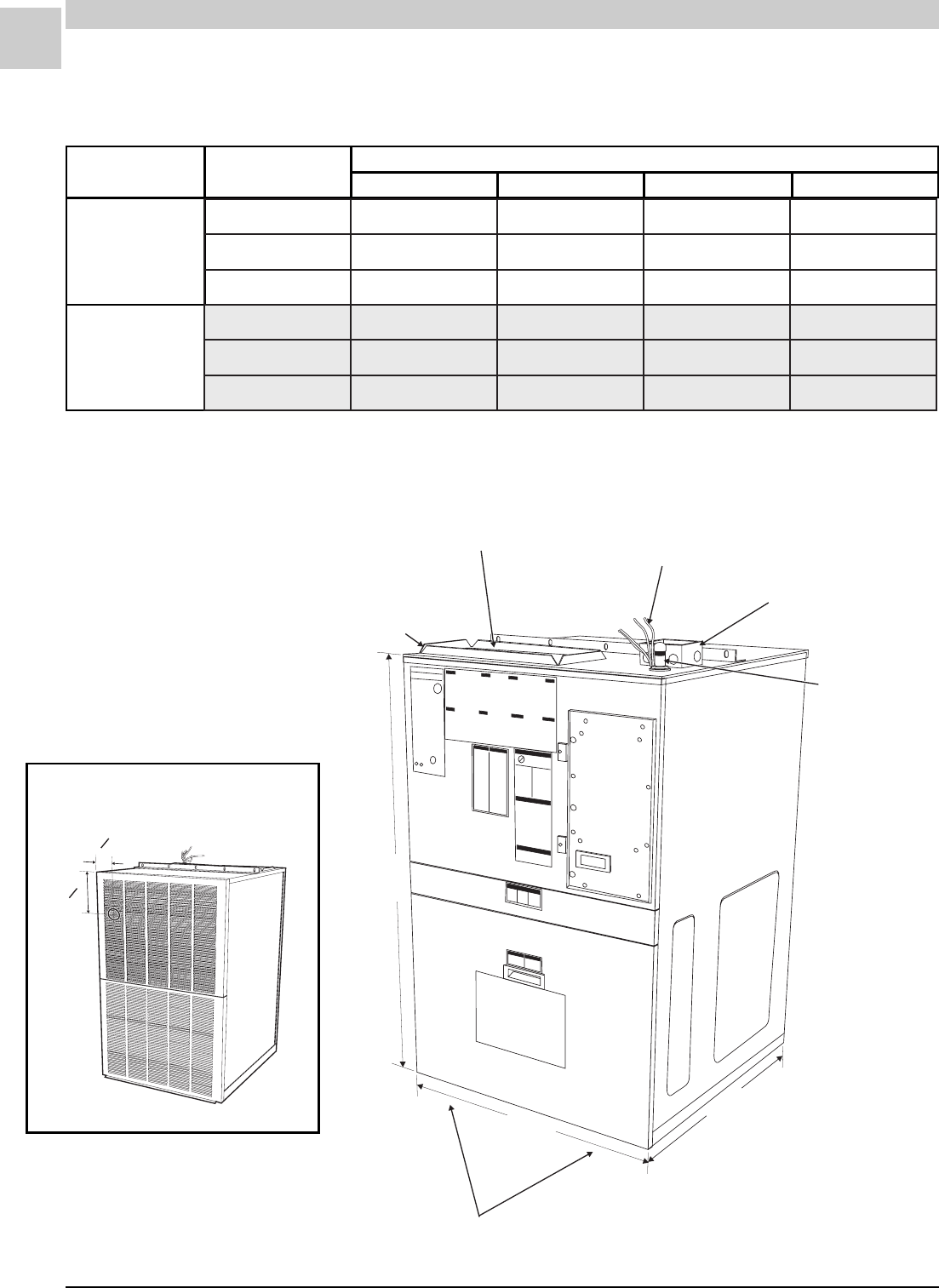
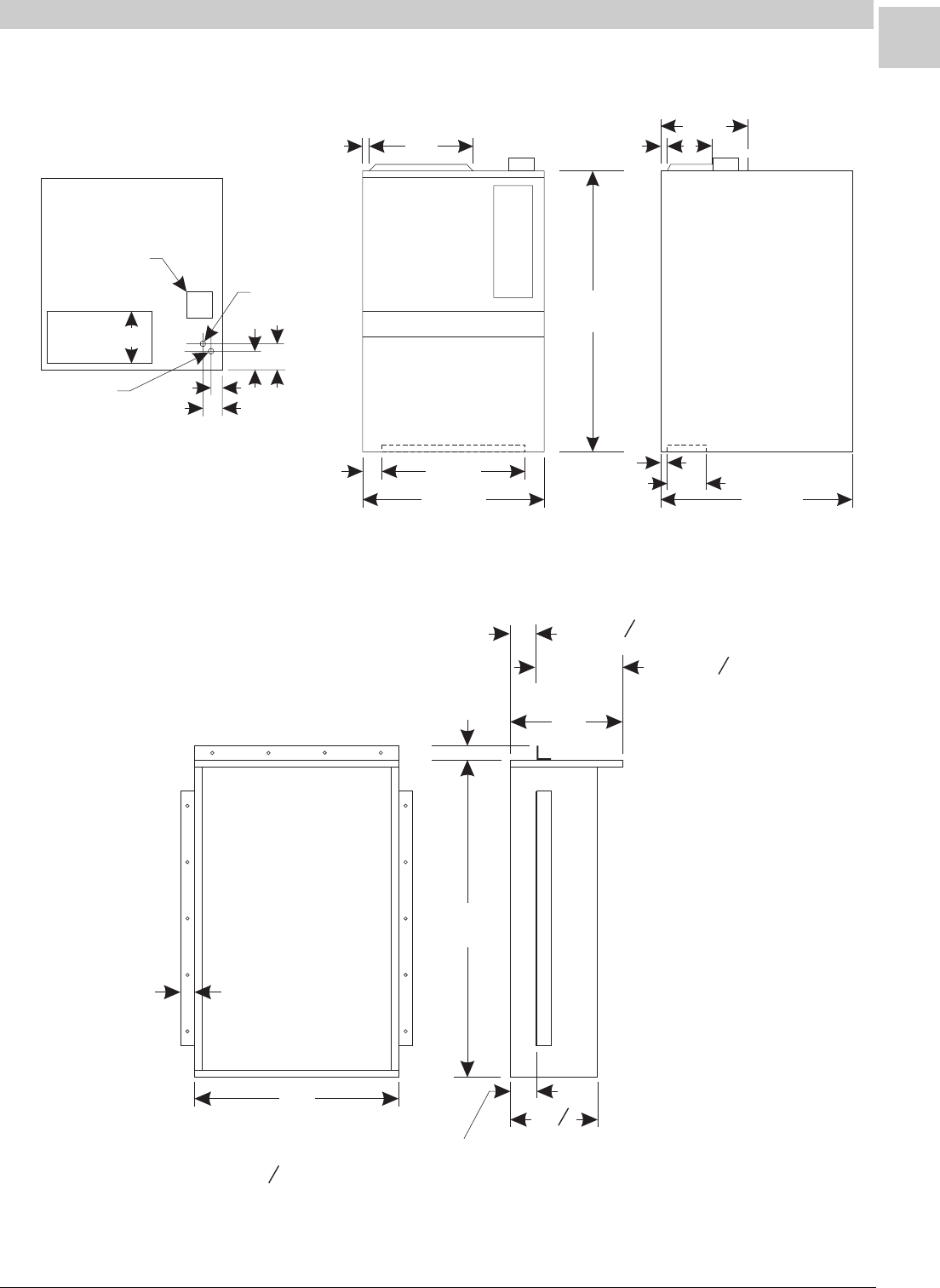
Dimensions (all measurements in inches)
Blower Performance
Model Blower Speed CFM @ ext. static pressure - in. w.c. with filter(s)
0.2 0.3 0.4 0.5
HWC122/123
HWC182,242,302
HWC183,243,303
SUPPLY AIR DUCT CONNECTION
8" x 16" LOW VOLTAGE
THERMOSTAT CONNECTIONS
HIGH VOLTAGE
JUNCTION BOX
4" x 4" x 2"
GAS LINE
CONNECTION
RETURN AIR OPENING ON BOTTOM
6" x 22"
¾" DUCT CONNECTION FLANGE
29
716
/
"
43
18
/
"
27
78
/
"
Table 1-8 Blower Performance - HWC Units
iH056516575045
deM574054524004
woL514504093083
iH 578 528 577 527
deM 058 508 067 017
woL 036 506 575 055
4
12
"
6
34
"
Measurements from Side and
Top to Center of Vent Outlet
1-7
SRM-HW/HWC 8/99
Service Reference Manual SPECIFICATIONS
Wall Sleeve (all measurements in inches)
22
16 8
6
Return
Supply
11
1
Supply
Low
Voltage
Line Voltage
Box
½ Gas Inlet 3
8
4
1
3
/
4
2
7
/
8
13
3
/
8
43
1
/
8
27
7
/
8
29
7
/
16
2
7
/
8
Dimensions (cont.)
29
16
45
2
2
1 or 3
34
Flanges may be assembled
1" or 3 from this side of the sleeve
34
"
12
12
"
15 or 12
14

Service Reference Manual SEQUENCE OF OPERATIONS
2-1
SRM-HW/HWC 2/99
Section 2 - Sequence of Operation
HWC123,183,243,303........................ 2-4
Simplified Sequence ........................................ 2-5
Detailed Sequence .......................................... 2-6
POWER ...................................................................... 2-6
CALL FOR HEAT ........................................................ 2-6
LIMIT/ROLLOUT OPENS ........................................... 2-7
PRESSURE SWITCH OPENS (BLOCKED FLUE)..... 2-7
FAILED FLAME SENSE/TRIAL FOR IGNITION ......... 2-8
CALL FOR COOLING ................................................. 2-8
FAN ON....................................................................... 2-9
HW (Heating Only)
(w/UTEC 1097 Spark Ignition System) 2-10
Simplified Sequence ...................................... 2-11
Detailed Sequence ........................................ 2-12
POWER .................................................................... 2-12
CALL FOR HEAT ...................................................... 2-12
LIMIT/ROLLOUT OPENS ......................................... 2-13
PRESSURE SWITCH OPENS (BLOCKED FLUE)... 2-13
FAILED FLAME SENSE/TRIAL FOR IGNITION ....... 2-14
FAN ON..................................................................... 2-14
HWC122,182,242,302
(w/Fenwal 2461D Ignition Control) ..... 2-16
Simplified Sequence ...................................... 2-17
Detailed Sequence ........................................ 2-18
POWER .................................................................... 2-18
CALL FOR HEAT ...................................................... 2-18
LIMIT OPENS ........................................................... 2-19
PRESSURE SWITCH OPENS (BLOCKED FLUE)... 2-19
ROLLOUT SWITCH ACTIVATED.............................. 2-19
CALL FOR COOLING ............................................... 2-19
FAN ON..................................................................... 2-20
HW (Heating Only)
(w/Fenwal 2461D Ignition Control) ..... 2-22
Simplified Sequence ...................................... 2-23
Detailed Sequence ........................................ 2-24
POWER .................................................................... 2-24
CALL FOR HEAT ...................................................... 2-24
LIMIT OPENS ........................................................... 2-25
PRESSURE SWITCH OPENS (BLOCKED FLUE)... 2-25
ROLLOUT SWITCH ACTIVATED.............................. 2-25

SPECIFICATIONS Magic-Pak: HW/HWC
2-2
SRM-HW/HWC 2/99
HWC122,182,242,302
(w/Fenwal 05-29 Ignition Control) ....... 2-26
Simplified Sequence ...................................... 2-27
Detailed Sequence ........................................ 2-28
POWER .................................................................... 2-28
CALL FOR HEAT ...................................................... 2-28
FLAME SENSE......................................................... 2-29
LIMIT OPENS ........................................................... 2-29
ROLLOUT SWITCH ACTIVATED.............................. 2-29
CALL FOR COOLING ............................................... 2-29
FAN ON..................................................................... 2-30
HW (Heating Only)
(w/Fenwal 05-29 Ignition Control) ....... 2-32
Simplified Sequence ...................................... 2-33
Detailed Sequence ........................................ 2-34
POWER .................................................................... 2-34
CALL FOR HEAT ...................................................... 2-34
FLAME SENSE......................................................... 2-35
LIMIT OPENS ........................................................... 2-35
ROLLOUT SWITCH ACTIVATED.............................. 2-35
HWC123,183,243,303
w/Low Ambient Control ...................... 2-36
HWC122,182,242,302
w/Low Ambient Control ...................... 2-38

Service Reference Manual SEQUENCE OF OPERATIONS
2-3
SRM-HW/HWC 2/99
BLANK PAGE
SPECIFICATIONS Magic-Pak: HW/HWC
2-4
SRM-HW/HWC 2/99
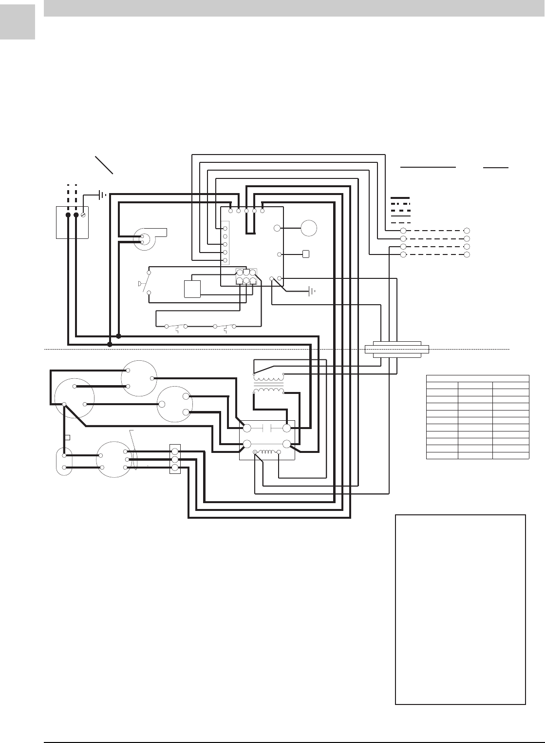
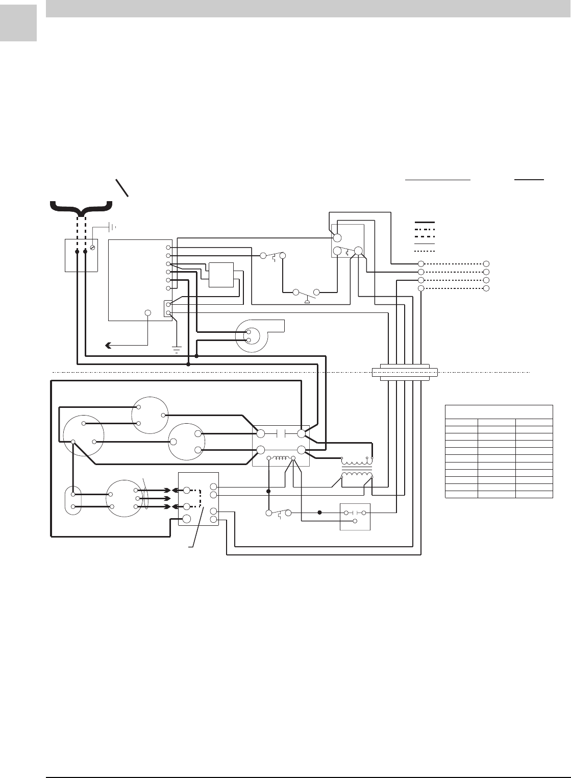
FIGURE 2-1 Connection Diagram
GREEN
BLACK
BLK
M
ORN
ORN
VIOLET
RED
BLUE
WHT
RED
BLACK
BLUE
YELLOW
WHITE
GREEN
RED
FLAME ROD
ELECTRODE
46
2
RGWCY
BLACK
BLACK BLACK
GAS
VALVE
MANUAL RESET
LIMIT SWITCH
COMBUSTION
BLOWER
RED
BLUE
YELLOW
RED
YELLOW
D
208 V
RED
BLUE
240 V
CAPACITORCAPACITOR
BLOWER
208/230-1-60
POWER SUPPLY COPPER CONDUCTORS
ONLY
}
THERMOSTAT
}
JUMPER REQUIRED
*
*
*
*
HIGH(BLACK)HIGH(BLACK)HIGH(BLACK)64HWC30364HWC303
HIGH(BLACK)MED (BLUE)51HWC30351HWC303
MED (BLUE)MED (BLUE)HIGH(BLACK)HIGH(BLACK)64HWC24364HWC243
MED (BLUE)MED (BLUE)MED (BLUE)51HWC24351HWC243
MED (BLUE)MED (BLUE)LOW (RED)38HWC24338HWC243
LOW (RED)LOW (RED)HIGH(BLACK)HIGH(BLACK)64HWC18364HWC183
LOW (RED)LOW (RED)MED (BLUE)51HWC18351HWC183
LOW (RED)LOW (RED)LOW (RED)38HWC183
MED (BLUE)MED (BLUE)HIGH(BLACK)HIGH(BLACK)38HWC12338HWC123
MED (BLUE)MED (BLUE)LOW (RED)26HWC12326HWC123
T2
T1
L2
L1
COOLINGCOOLINGHEATINGHEATINGMODELSMODELS
EVAP. MOTOR SPEED CONNECTIONSEVAP. MOTOR SPEED CONNECTIONS
BLACK
BLACK
RED
BLACK
BLACK
RED
RED
YELLOWYELLOW
BLUE
BLACK
VIOLET
YELLOW
RED
BLUEBLUE
BLACK
BROWN
BROWN
NOTE:
IF ANY OF THE ORIGINAL
WIRES ARE REPLACED, THE
SAME SIZE AND TYPE WIRE
MUST BE USED.
W
Y
G
R
LINE VOLTAGE-FACTORY
LINE VOLTAGE-FACTORY WHEN USED
LINE VOLTAGE-FIELD
LOW VOLTAGE-FACTORY
LOW VOLTAGE-FIELD
W
Y
G
R
GND
24VAC
UNUSED
HEAT
COOL
L1
CMB
L
H
R
C
S
FAN
COM HERM
SEE CHARTCHART
FOR WIRING
PRESSURE
SWITCH
AUTO RESET
LIMIT SWITCH
IGNITION
CONTROLCONTROL
TRANSFORMERTRANSFORMER
CONTACTOR
BLOWER
CONTROL
BLOWER
CONTROL
BLOWER
MOTOR
CAPACITOR-RUN
CONDENSER FANCONDENSER FAN
COMP
CONNECTORCONNECTOR BLOCKBLOCK
ORN
VIOLET
BLK
CONNECTION DIAGRAMCONNECTION DIAGRAM
CIRCUITS ENERGIZED
OPERATING MODE CIRCUIT
HEATING R-W
COOLING R-G-Y
FAN R-G
3
1
5
1
2
3
4
5
#45004-1
DIAGNOSTICS
The following blower/ignition control board
LED codes will indicate normal or abnormal
operations:
SLOW FLASH Normal Operation, No
Call for Heat
FAST FLASH Normal Operation, Call for
Heat
2 FLASH System Lockout - Failed to
Detect or Sustain Flame
3 FLASH Pressure Switch Open or
Closed
4 FLASH High Limit or Rollout
Switch Open
5 FLASH Flame Sensed and Gas
Valve Not Energized
STEADY Internal Failure
(Micro-controller Failure;
Self-check)
HWC123, 183, 243, 303
(w/United Technologies 1097 Spark Ignition System)
Note: On units that are equipped with a low ambient switch (designated
with an “SA” in the model number), sequence of operation during
cooling call is modified when outdoor temperatures fall below the
normal operating range. For more information on the low ambient
switch equipped version of this unit, see the section beginning on
page 2-36.

Service Reference Manual SEQUENCE OF OPERATIONS
2-5
SRM-HW/HWC 2/99
Simplified Sequence - HWC123,183, 243, 303
Refer to Figure 2-1
• 208/230V power is supplied to the junction box on
top of the unit
• 24V power is supplied from the unit transformer to
the thermostat
CALL FOR HEAT
1. The thermostat closes the R-W circuit, sending a
24-volt signal to the unit.
2. The 24-volt signal energizes the combustion blower,
causing the pressure switch to close.
3. The combustion blower runs for 30 seconds as a
pre-purge to trial for ignition.
4. The ignition control energizes the spark ignition and
opens the gas valve, causing the burners to light.
When the gas valve energizes, a 30-second circu-
lating air blower “on” delay begins.
5. Flame sense is sent to the ignition control through
the flame sensor and flame sense wire.
6. After the 30-second delay, the circulating air blower
energizes and runs until the heat call is satisfied.
7. When the heat call is satisfied, the gas valve de-
energizes. This shuts down the burners.
8. A 5-second combustion blower post-purge delay
and a 120-second circulating air blower “off” delay
start.
9. After the delay times elapse, the combustion blower
and the circulating air blower stop.
FLAME SENSE
1. After the burners have been lit, the ignition control
starts a 10-second trial for ignition delay.
2. If after 10 seconds a flame has not been sensed by
the ignition control, the ignition control de-energizes
the gas valve and the spark ignitor.
3. The unit initiates three trials for ignition (flame
sense) before system lockout.
4. System lockout lasts 60 minutes or until power is
reset to unit (whichever comes first).
CALL FOR COOLING
1. The thermostat energizes the R, Y and G circuit,
sending a 24-volt signal to the cooling contactor and
the ignition control to start the cooling sequence.
2. The contactor closes immediately, causing the
compressor and the condenser fan to run.
3. The 24-volt Y signal starts a 5-second circulating air
blower “on” delay.
4. After 5 seconds, the circulating air blower starts and
runs until the R, Y and G circuit is interrupted by the
thermostat.
5. When the R, Y and G circuit is interrupted, the
cooling contactor immediately de-energizes. This
causes the compressor and the condenser fan to
stop.
6. The ignition control starts a 90-second circulating
air blower “off” delay.
7. After 90 seconds, the circulating air blower stops.
FAN ON
1. The thermostat energizes the R-G circuit, causing
the circulating air blower to energize in cooling
speed.
2. The circulating air blower remains running in cooling
speed until the thermostat is switched to the “AUTO”
position.
Detailed Sequence follows

SPECIFICATIONS Magic-Pak: HW/HWC
2-6
SRM-HW/HWC 2/99
Detailed Sequence - HWC123, 183, 243, 303
Refer to Figure 2-1
POWER
Line Voltage
With the unit at rest (no call from the thermostat), line
voltage will be present:
L1 Power
1. Through the L1 black lead to the L1 terminal on the
ignition control
2. At the L1 contactor terminal
3. At the transformer terminal marked 208-240V
L2 Power
1. Through the L2 black lead to the induced draft
blower
2. At the L2 contactor terminal
3. A transformer common terminal
4. At the T2 contactor terminal
5. At the R terminal of the compressor
6. At the capacitor common terminals
Low Voltage (24 VAC)
With the unit at rest (no call from the thermostat), 24
volts A/C will be present:
1. From the transformer 24V terminal to pin 4 of the
6-pin chassis low voltage harness
2. From pin 4 of the chassis low voltage harness to the
24VAC hot terminal on the ignition control
3. From the 24VAC hot terminal to pin 5 of the 5-pin
thermostat harness (internal to board)
4. From the 24VAC hot terminal also to pin 6 of the 6-
pin ignition wire harness
5. From pin 6 of the ignition wire harness through the
auto reset limit switch and the manual reset
rollout switch to pin 1 of the 6-pin ignition wire
harness
Note: While the unit is at rest, the green LED shows
consistent slow flash. This indicates normal
operation - system at rest (standby mode).
CALL FOR HEAT
Line Voltage
The ignition control receives a signal from the R-W
circuit indicating a call for heat.
1. The combustion blower relay energizes, sending
L1 power to CMB BLWR terminal on the ignition
control. This causes the combustion blower to
start by completing the line voltage circuit through
the L2 wire connection in the unit.
2. As the 24-volt signal is sent to pin 4 of the 6-pin
ignition wire harness by the ignition control, a 30-
second circulating air blower “on” delay starts.
After the delay, the ignition control energizes the
heat speed blower relay. This sends L1 power to the
ACB HEAT terminal on the ignition control.
3. L1 power is then sent to the circulating air blower
terminal block where it is connected to the blower
motor. The circulating air blower starts by
completing the L1-L2 circuit through the L2 connec-
tion at the blower motor capacitor.
4. The combustion blower and the circulating air
blower continue to run until the R-W circuit is
interrupted. After a 5-second post-purge delay, the
CMB BLWR terminal on the ignition control de-
energizes. This interrupts L1 power to the combus-
tion blower. After a 120-second circulating air
blower “off” delay, the ACB HEAT terminal de-
energizes. This interrupts L1 to the circulating air
blower. As L1 power is interrupted, the blowers
shut off.
Low Voltage
1. A call for heat closes the R-W circuit, sending a 24-
volt signal to the low voltage white wire in the unit.
2. The 24-volt signal is received at pin 3 of the 5-pin
thermostat harness on the ignition control.
3. The 24-volt signal causes the combustion blower
relay to close, causing the combustion blower to
run. At this time, a 24-volt signal is also sent out
through pin 2 of the 6-pin ignition wire harness.
4. The 24-volt signal from pin 2 of the 6-pin ignition
wire harness energizes one side of the Normally
Open pressure switch. As the induced draft
blower reaches full speed, the pressure switch
closes and a 24-volt signal is sent to pin 5 of the 6-
pin ignition wire harness.
5. When the 24-volt signal is received at pin 5 of the 6-
pin ignition wire harness, the ignition control starts
a 30-second pre-purge delay.
6. After the 30-second pre-purge, the ignition control
initiates a trial for ignition. The spark ignition
cable terminal and pin 4 of the 6-pin ignition wire
harness energize simultaneously.
7. When the 24-volt signal is present at pin 4 of the 6-
pin ignition wire harness, the ignition control starts
a 30-second circulating air blower “on” delay.
8. The 24-volt signal from pin 4 of the 6-pin ignition
wire harness is received at the gas valve, causing
it to open and the burners to ignite.

Service Reference Manual SEQUENCE OF OPERATIONS
2-7
SRM-HW/HWC 2/99
9. After 30-second “on” delay, the circulating air
blower relay energizes the heat terminal and the
circulating air blower is energized.
10. The unit will continue to operate normally until the
R-W circuit is interrupted.
11. When the heat call is satisfied, the thermostat will
interrupt the R-W circuit. This causes the 24-volt
signal to the white wire in the unit to be de-ener-
gized.
12. The gas valve closes immediately as 24V through
pin 4 of the 6-pin ignition wire harness is de-
energized by the ignition control.
13. The ignition control initiates a 120-second circu-
lating air blower “off” delay and 5-second com-
bustion blower post-purge delay.
14. After 5 seconds, the combustion blower shuts off.
15. After 120 seconds, the circulating air blower
shuts off and the system returns to standby mode.
Note: During a call for heat, the green LED shows
consistent fast flash (as long as the R-W circuit is
closed). When the R-W circuit is interrupted
(indicating the heat call has been satisfied), the
green LED returns to a consistent slow flash.
LIMIT/ROLLOUT OPENS
In all modes of operation, 24VAC is supplied to the
ignition control 24VAC hot terminal and is passed
through the ignition control to pin 6 of the 6-pin
ignition wire harness.
1. A 24-volt signal is sent from pin 6 of the 6-pin
ignition wire harness to one side of the Normally
Closed manual reset rollout switch, across the
rollout switch to one side of the Normally Closed
auto reset limit switch and across the limit switch
to pin 1 of the 6-pin ignition wire harness.
2. This circuit energizes whenever line voltage power
is supplied to the unit.
3. If the circuit is interrupted by either switch opening,
the 24-volt signal to pin 1 of the 6-pin ignition wire
harness de-energizes.
4. This causes the combustion blower relay to
energize, sending L1 power to the CMB BLWR
terminal on the ignition control. It also causes the
circulating air blower heat speed relay to ener-
gize, sending L1 power to the ACB HEAT terminal
on the ignition control. This causes both blowers
to start immediately.
5. The ignition control lockouts the spark ignition
cable terminal and pin 4 of the 6-pin ignition wire
harness until the 24-volt signal is restored at pin 1 of
the 6-pin ignition wire harness.
6. The circulating air blower and the combustion
blower are energized until the 24-volt signal is
restored at pin 1 of the 6-pin ignition wire harness.
7. The green ignition control LED shows a 4 flash fault
code (indicating limit switch/rollout switch open).
8. When the 24-volt signal is restored at pin 1 of the 6-
pin ignition wire harness, the ignition control starts
a 5-second combustion blower post-purge delay
and a 120-second circulating air blower “off”
delay.
9. Once the delays have timed out, both blowers stop
and the green LED flashes a consistent slow flash if
no heat call is present. (A consistent fast flash
appears if there is a call for heat.)
Note: The limit switch resets automatically when
temperatures are acceptable, but the rollout
switch must be manually reset by pushing in on
the small button on top of the switch.
The reason why the switches opened must be
determined before any corrective action is taken.
PRESSURE SWITCH OPENS (BLOCKED FLUE)
When the R-W circuit is energized, a 24-volt signal is
sent to the ignition control. This starts the call for
heat.
1. The 24-volt signal from the R-W circuit energizes
the combustion blower relay, sending L1 power to
the CMB BLWR terminal on the ignition control.
This starts the ignition control.
2. At the same time the combustion blower relay
energizes, the 24-volt signal is sent to pin 2 of the 6-
pin ignition wire harness and from pin 2 to one side
of the Normally Open pressure switch.
3. When the combustion blower causes the pres-
sure switch to close, a 24-volt signal is sent across
the switch to pin 5 of the 6-pin ignition wire harness.
The 24-volt signal energizes at pin 5 and the ignition
sequence continues.
4. If the combustion blower fails to close the pres-
sure switch, the 24-volt signal is not sent to pin 5
of the 6-pin ignition wire harness and the ignition
control does not initiate a 30-second pre-purge
delay.
5. No signal is sent to the spark ignition cable
terminal on the ignition control or to the gas valve
through pin 4 of the 6-pin ignition wire harness.
6. The combustion blower continues to run for 60
seconds. After 60 seconds, the ignition control
automatically de-energizes the combustion
blower relay. This interrupts L1 power to the CMB
BLWR terminal on the ignition control.
7. The combustion blower remains de-energized for
approximately six minutes. During this 6-minute
lockout, the green LED flashes three times (indicat-
ing pressure switch fault—open or closed).

SPECIFICATIONS Magic-Pak: HW/HWC
2-8
SRM-HW/HWC 2/99
8. The 24-volt signal will only be supplied to the limit
switch circuit through pin 6 of the 6-pin ignition wire
harness and to the pressure switch circuit through
pin 2 of the 6-pin ignition wire harness.
9. The system will repeat this sequence until the
pressure switch closes and the 24-volt signal is
restored at pin 5 of the 6-pin ignition wire harness.
FAILED FLAME SENSE/TRIAL FOR IGNITION
When the pressure switch closes and a 24-volt signal
is sent to pin 5 of the 6-pin ignition wire harness, the
spark ignition cable terminal and pin 4 of the 6-pin
ignition wire harness energize.
1. As spark voltage is supplied to the ignitor elec-
trodes, the gas valve opens and this causes the
burners to ignite.
2. The ignition control continues to energize spark
voltage until a flame sense signal is supplied to the
flame terminal on the ignition control.
3. If a flame sense signal is not received at the flame
terminal on the ignition control, the spark igni-
tion cable terminal remains energized for 10
seconds.
4. After the 10-second trial for ignition, the ignition
control de-energizes the spark ignition cable
terminal and pin 4 of the 6-pin ignition wire harness.
This causes the gas valve to close and the elec-
trode spark to stop.
5. Once the 24-volt signal is sent to pin 4 of the 6-pin
ignition wire harness, a 30-second circulating air
blower “on” delay starts. After the delay is timed
out, the circulating air blower starts.
6. After the spark ignition cable terminal de-ener-
gizes, the ignition control initiates a 30-second
combustion blower inter-purge delay.
7. After 30-second inter-purge, the ignition control
energizes the spark ignition cable terminal and
pin 4 of the 6-pin ignition wire harness. If the flame
sense signal is received at the flame terminal of the
ignition control, the unit continues heat call.
8. If the flame sense signal is not received, the system
goes through three trials following the above
sequence.
9. After three trials, the system goes into lockout and
only the high limit switch circuit and pressure
switch circuit remain energized during the 60-
minute lockout period.
10. If the flame sense is lost during the heat cycle, the
gas valve de-energizes immediately and the
system goes into the trial sequence.
CALL FOR COOLING
Line Voltage
1. L2 power passes through the fixed closed L2-T2
terminals on the contactor to the RUN terminal of
the compressor and the COMMON terminal of the
capacitor.
2. L1 power is sent to the L1 terminal of the contactor.
When the Y signal energizes the contactor, the T2
terminal becomes energized. L1 power is sent to
the compressor COMMON terminal and the
condenser fan. This energizes the compressor
and condenser fan motors.
3. When pin 1 (Y terminal) of the 5-pin thermostat
harness receives a 24-volt signal from the thermo-
stat, a 5-second circulating air blower delay
starts.
4. After the 5-second delay, the ignition control
energizes the cooling speed relay. This sends L1
power to the ACB COOL terminal of the ignition
control.
5. L1 power is sent to the circulating air blower
terminal block, energizing the circulating air
blower motor.
6. When the R, Y and G circuit is interrupted by the
thermostat, the contactor is immediately de-
energized. This interrupts L1 power to the com-
pressor and condenser fan motors, stopping
both.
7. The ignition control starts a 90-second circulat-
ing air blower “off” delay, after which the ACB
COOL terminal de-energizes. This interrupts L1
power to the circulating air blower motor, causing
it to stop.
Low Voltage
1. The thermostat energizes the R, Y and G circuit,
sending a 24-volt signal to the contactor coil and to
pin 1 of the 5-pin thermostat harness connected to
the ignition control.
2. The contactor closes immediately upon receiving
the 24-volt signal, causing the compressor and
condenser fan motors to start.
3. The 24-volt signal is also sent to pin 1 of the 5-pin
thermostat harness, initiating a 5-second circulat-
ing air blower “on” delay.
4. After the 5-second delay, the ignition control
energizes the cooling speed relay and the circulat-
ing air blower starts.
5. When the cooling call is satisfied, the thermostat
interrupts the R, Y and G circuit. The contactor
de-energizes immediately, causing the compressor
and the condenser fan to stop. The ignition
control starts a 90-second circulating air blower
“off” delay.

Service Reference Manual SEQUENCE OF OPERATIONS
2-9
SRM-HW/HWC 2/99
6. After the 90-second delay, the ignition control de-
energizes the cooling speed relay and the circulat-
ing air blower stops.
FAN ON
1. When the thermostat is switched to the “FAN ON”
position, the R-G circuit sends a 24-volt signal to
pin 4 of the 5-pin thermostat harness.
2. The 24-volt signal energizes the cooling speed
relay, sending L1 power to the ACB COOL terminal
of the ignition control.
3. L1 power is sent to the circulating air blower
terminal block, causing the circulating air blower
to run in cooling speed.
4. The circulating air blower continues to run in
cooling speed until the thermostat is switched to
“AUTO”, interrupting the R-G circuit.
Note: With the thermostat in the “FAN ON” position
during heat call, ignition control will not energize
the heat speed relay. The circulating air blower
continues to run in cooling speed unless the limit
switch circuit opens, which would cause the heat
speed relay and the induced draft blower relay
to become energized. This would de-energize the
cooling speed relay until either the limit switch
circuit is closed or the thermostat is switched to
the “AUTO” position.
SPECIFICATIONS Magic-Pak: HW/HWC
2-10
SRM-HW/HWC 2/99
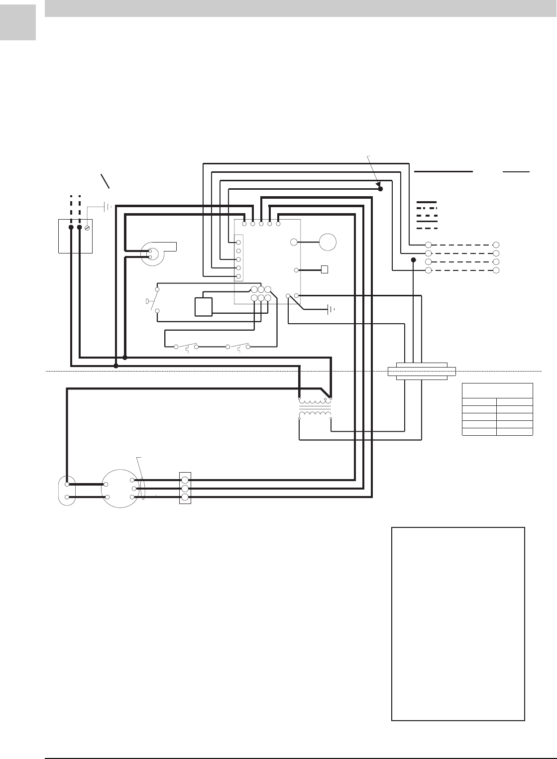
#45008-2
HIGH (BLACK)
64HW
MED (BLUE)
51HW
HIGH (BLACK)38HW
LOW (RED)LOW (RED)26HW
HEATINGHEATINGMODELS
EVAP. MOTOR
SPEED CONNECTIONS
EVAP. MOTOR
SPEED CONNECTIONS
GREEN
M
ORANGE
ORANGE
VOILET
VOILET
RED
BLUE
WHT
RED
BLACK
BLUE
YELLOW
WHITE
GREEN
RED
FLAME ROD
ELECTRODE
456
3
2
1
RGWCY
BLACK
BLACK BLACK
GAS
VALVE
MANUAL RESET
LIMIT SWITCH
COMBUSTION
BLOWER
BLACK
BLUE
YELLOW
RED
208 V
RED
BLUE
240 V
CAPACITORCAPACITOR
BLOWER
208/230-1-60
POWER SUPPLY COPPER CONDUCTORS
ONLY
}
THERMOSTAT
}
BLACK
BLACK
RED
YELLOW
RED
BLUE
BLACK
BROWN
CONNECTION DIAGRAM
W
Y
G
R
W
Y
G
R
GND
24VAC
UNUSED
HEAT
COOL
L1
CNB
L
SEE
CHART
FOR WIRING
PRESSURE
SWITCH
AUTO RESET
LIMIT SWITCH
IGNITION
CONTROL
BLOWER
MOTOR
CONNECTOR
BLOCK
WIRE NUT
TERMINAL BLOCK
CIRCUITS ENERGIZED
OPERATING MODE CIRCUIT
HEATING R-W
COOLING R-G-Y
FAN R-G
LINE VOLTAGE-FACTORY
LINE VOLTAGE-FACTORY WHEN USED
LINE VOLTAGE-FIELD
LOW VOLTAGE-FACTORY
LOW VOLTAGE-FIELD
NOTE:
IF ANY OF THE ORIGINAL
WIRES ARE REPLACED, THE
SAME SIZE AND TYPE WIRE
MUST BE USED.
YELLOW
TRANSFORMER
ORANGE
H
1
2
3
4
5
DIAGNOSTICS
The following blower/ignition control board
LED codes will indicate normal or abnormal
operations:
SLOW FLASH Normal Operation, No
Call for Heat
FAST FLASH Normal Operation, Call for
Heat
2 FLASH System Lockout - Failed to
Detect or Sustain Flame
3 FLASH Pressure Switch Open or
Closed
4 FLASH High Limit or Rollout
Switch Open
5 FLASH Flame Sensed and Gas
Valve Not Energized
STEADY Internal Failure
(Micro-controller Failure;
Self-check)
HW (Heating Only)
(w/United Technologies 1097 Spark Ignition System)
FIGURE 2-2 Connection Diagram

Service Reference Manual SEQUENCE OF OPERATIONS
2-11
SRM-HW/HWC 2/99
Simplified Sequence - HW (w/UTEC 1097 Board)
Refer to Figure 2-2
CALL FOR HEAT
1. The indoor thermostat energizes the R-W circuit,
sending a 24-volt signal to the ignition control.
2. The 24-volt signal causes the induced draft blower
to start, which closes the pressure switch.
3. Once the pressure switch closes, a 30-second
induced draft blower pre-purge starts.
4. After the 30-second induced draft blower pre-purge,
the gas valve opens and the burners ignite. This
starts a 30-second circulating air blower “on” delay.
5. The unit continues to operate in the heat mode until
the indoor thermostat setting is reached. At that
time, the R-W circuit is interrupted.
6. The 24-volt signal to the ignition control is inter-
rupted, causing the gas valve to close and the
burners to shut down.
7. A 5-second post-purge starts and following that the
induced draft blower stops.
8. A 120-second circulating air blower “off” delay
starts. After the elapsed time, the circulating air
blower stops.
FAN ON
1. When the thermostat is switched to the “FAN ON”
position, a 24-volt signal is sent to the ignition
control.
2. The ignition control immediately energizes the
cooling speed of the circulating air blower.
3. The circulating air blower runs in the cooling speed
until the thermostat fan switch is moved back to the
“AUTO” position. At this time, the circulating air
blower stops.
During the call for “FAN ON”, the circulating air blower
heat speed will not be energized by the ignition control
unless the limit switch circuit is interrupted.
Detailed Sequence follows

SPECIFICATIONS Magic-Pak: HW/HWC
2-12
SRM-HW/HWC 2/99
Detailed Sequence - HW (w/UTEC 1097 Board)
Refer to Figure 2-2
POWER
Line Voltage
With the unit at rest (no call from the thermostat), line
voltage will be present:
L1 Power
1. Through the L1 black lead to the L1 terminal on the
ignition control
2. At the transformer terminal marked 208-240V
L2 Power
1. Through the L2 black lead to the induced draft
blower
2. Transformer common terminal
3. At the circulating air blower capacitor terminal
Low Voltage (24 VAC)
With the unit at rest (no call from the thermostat), 24
volts A/C will be present:
1. At the transformer 24V terminal
2. At the 24VAC hot terminal on the ignition control
3. At pin 5 of the 5-pin thermostat harness (red wire
pin)
4. At pin 6 of the 6-pin ignition wire harness
5. Through the auto reset limit switch and the
manual reset rollout switch to pin 1 of the 6-pin
ignition wire harness
Note: While the unit is at rest, the green LED shows
consistent slow flash. This indicates normal
operation - system at rest (standby mode).
CALL FOR HEAT
Line Voltage
The ignition control receives a signal from the R-W
circuit indicating a call for heat.
1. The combustion blower relay energizes, sending
L1 power to CMB BLWR terminal on the ignition
control. This causes the combustion blower to
start.
2. As the 24-volt signal is sent to pin 4 of the 6-pin
ignition wire harness by the ignition control, a 30-
second circulating air blower “on” delay starts.
After the delay, the ignition control energizes the
heat speed blower relay. This sends L1 power to
the ACB HEAT terminal on the ignition control.
3. L1 power is then sent to the circulating air blower
terminal block where it is connected to the blower
motor, starting the circulating air blower.
4. The combustion blower and the circulating air
blower continue to run until the R-W circuit is
interrupted. After a 5-second post-purge delay, the
CMB BLWR terminal on the ignition control de-
energizes. This interrupts L1 power to the combus-
tion blower. After a 120-second circulating air
blower “off” delay, the ACB HEAT terminal de-
energizes. This interrupts L1 to the circulating air
blower. As L1 power is interrupted, the blowers
shut off.
Low Voltage
1. A call for heat closes the R-W circuit, sending a 24-
volt signal to the low voltage white wire in the unit.
2. The 24-volt signal is received at pin 3 of the 5-pin
thermostat harness on the ignition control.
3. The 24-volt signal causes the combustion blower
relay to close, causing the combustion blower to
run. At this time, a 24-volt signal is also sent out
through pin 2 of the 6-pin ignition wire harness.
4. The 24-volt signal from pin 2 of the 6-pin ignition
wire harness energizes one side of the Normally
Open pressure switch. As the induced draft
blower reaches full speed, the pressure switch
closes and a 24-volt signal is sent to pin 5 of the 6-
pin ignition wire harness.
5. When the 24-volt signal is received at pin 5 of the 6-
pin ignition wire harness, the ignition control starts
a 30-second pre-purge delay.
6. After the 30-second pre-purge, the ignition control
initiates a trial for ignition. The spark ignition
cable terminal and pin 4 of the 6-pin ignition wire
harness energize simultaneously.
7. When the 24-volt signal is present at pin 4 of the 6-
pin ignition wire harness, the ignition control starts
a 30-second circulating air blower “on” delay.
8. The 24-volt signal from pin 4 of the 6-pin ignition
wire harness is received at the gas valve, causing
it to open and the burners to ignite.
9. After 30-second “on” delay, the circulating air
blower relay energizes the heat terminal and the
circulating air blower is energized.
10. The unit will continue to operate normally until the
R-W circuit is interrupted.
11. When the heat call is satisfied, the thermostat will
interrupt the R-W circuit. This causes the 24-volt
signal to the white wire in the unit to be de-ener-
gized.

Service Reference Manual SEQUENCE OF OPERATIONS
2-13
SRM-HW/HWC 2/99
12. The gas valve closes immediately as 24V through
pin 4 of the 6-pin ignition wire harness is de-
energized by the ignition control.
13. The ignition control initiates a 120-second circu-
lating air blower “off” delay and 5-second com-
bustion blower post-purge delay.
14. After 5 seconds, the combustion blower shuts off.
15. After 120 seconds, the circulating air blower
shuts off and the system returns to standby mode.
Note: During a call for heat, the green LED shows
consistent fast flash (as long as the R-W circuit is
closed). When the R-W circuit is interrupted
(indicating the heat call has been satisfied), the
green LED returns to a consistent slow flash.
LIMIT/ROLLOUT OPENS
In all modes of operation, 24VAC is supplied to the
ignition control 24VAC hot terminal and is passed
through the ignition control to pin 6 of the 6-pin
ignition wire harness.
1. A 24-volt signal is sent from pin 6 of the 6-pin
ignition wire harness to one side of the Normally
Closed manual reset rollout switch, across the
rollout switch to one side of the Normally Closed
auto reset limit switch and across the limit switch
to pin 1 of the 6-pin ignition wire harness.
2. This circuit energizes whenever line voltage power
is supplied to the unit.
3. If the circuit is interrupted by either switch opening,
the 24-volt signal to pin 1 of the 6-pin ignition wire
harness de-energizes.
4. This causes the combustion blower relay to
energize, sending L1 power to the CMB BLWR
terminal on the ignition control. It also causes the
circulating air blower heat speed relay to ener-
gize, sending L1 power to the ACB HEAT terminal
on the ignition control. This causes both blowers
to start immediately.
5. The ignition control lockouts the spark ignition
cable terminal and pin 4 of the 6-pin ignition wire
harness until the 24-volt signal is restored at pin 1 of
the 6-pin ignition wire harness.
6. The circulating air blower and the combustion
blower are energized until the 24-volt signal is
restored at pin 1 of the 6-pin ignition wire harness.
7. The green ignition control LED shows a 4 flash fault
code (indicating limit switch/rollout switch open).
8. When the 24-volt signal is restored at pin 1 of the 6-
pin ignition wire harness, the ignition control starts
a 5-second combustion blower post-purge delay
and a 120-second circulating air blower “off”
delay.
9. Once the delays have timed out, both blowers stop
and the green LED flashes a consistent slow flash if
no heat call is present. (A consistent fast flash
appears if there is a call for heat.)
Note: The limit switch resets automatically when
temperatures are acceptable, but the rollout
switch must be manually reset by pushing in on
the small button on top of the switch.
The reason why the switches opened must be
determined before any corrective action is taken.
PRESSURE SWITCH OPENS (BLOCKED FLUE)
When the R-W circuit is energized, a 24-volt signal is
sent to the ignition control. This starts the call for
heat.
1. The 24-volt signal from the R-W circuit energizes
the combustion blower relay, sending L1 power to
the CMB BLWR terminal on the ignition control.
This starts the ignition control.
2. At the same time the combustion blower relay
energizes, the 24-volt signal is sent to pin 2 of the 6-
pin ignition wire harness and from pin 2 to one side
of the Normally Open pressure switch.
3. If the combustion blower causes the pressure
switch to close, a 24-volt signal is sent across the
switch to pin 5 of the 6-pin ignition wire harness.
The 24-volt signal energizes at pin 5 and the ignition
sequence continues.
4. If the combustion blower fails to close the pres-
sure switch, the 24-volt signal is not sent to pin 5
of the 6-pin ignition wire harness and the ignition
control does not initiate a 30-second pre-purge
delay.
5. No signal is sent to the spark ignition cable
terminal on the ignition control or to the gas valve
through pin 4 of the 6-pin ignition wire harness.
6. The combustion blower continues to run for 60
seconds. After 60 seconds, the ignition control
automatically de-energizes the combustion
blower relay. This interrupts L1 power to the CMB
BLWR terminal on the ignition control.
7. The combustion blower remains de-energized for
approximately six minutes. During this 6-minute
lockout, the green LED flashes three times (indicat-
ing pressure switch fault—open or closed).
8. The 24-volt signal will only be supplied to the limit
switch circuit through pin 6 of the 6-pin ignition wire
harness and to the pressure switch circuit through
pin 2 of the 6-pin ignition wire harness.
9. The system will repeat this sequence until the
pressure switch closes and the 24-volt signal is
restored at pin 5 of the 6-pin ignition wire harness.

SPECIFICATIONS Magic-Pak: HW/HWC
2-14
SRM-HW/HWC 2/99
FAILED FLAME SENSE/TRIAL FOR IGNITION
When the pressure switch closes and a 24-volt signal
is sent to pin 5 of the 6-pin ignition wire harness, the
spark ignition cable terminal and pin 4 of the 6-pin
ignition wire harness energize.
1. As spark voltage is supplied to the ignitor elec-
trodes, the gas valve opens and this causes the
burners to ignite.
2. The ignition control continues to energize spark
voltage until a flame sense signal is supplied to the
flame terminal on the ignition control.
3. If a flame sense signal is not received at the flame
terminal on the ignition control, the spark igni-
tion cable terminal remains energized for 10
seconds.
4. After the 10-second trial for ignition, the ignition
control de-energizes the spark ignition cable
terminal and pin 4 of the 6-pin ignition wire harness.
This causes the gas valve to close and the elec-
trode spark to stop.
5. Once the 24-volt signal is sent to pin 4 of the 6-pin
ignition wire harness, a 30-second circulating air
blower “on” delay starts. After the delay is timed
out, the circulating air blower starts.
6. After the spark ignition cable terminal de-ener-
gizes, the ignition control initiates a 30-second
combustion blower inter-purge delay.
7. After 30-second inter-purge, the ignition control
energizes the spark ignition cable terminal and
pin 4 of the 6-pin ignition wire harness. If the flame
sense signal is received at the flame terminal of the
ignition control, the unit continues heat call.
8. If the flame sense signal is not received, the system
goes through three trials following the above
sequence.
9. After three trials, the system goes into lockout and
only the limit switch circuit and pressure switch
circuit remain energized during the 60-minute
lockout period.
10. If the flame sense is lost during the heat cycle, the
gas valve de-energizes immediately and the
system goes into the trial sequence.
FAN ON
1. When the thermostat is switched to the “FAN ON”
position, the R-G circuit sends a 24-volt signal to
pin 4 of the 5-pin thermostat harness.
2. The 24-volt signal energizes the cooling speed
relay, sending L1 power to the ACB COOL terminal
of the ignition control.
3. L1 power is sent to the circulating air blower
terminal block, causing the circulating air blower
to run in cooling speed.
4. The circulating air blower continues to run in
cooling speed until the thermostat is switched to
“AUTO”, interrupting the R-G circuit.
Note: With the thermostat in the “FAN ON” position
during heat call, ignition control will not energize
the heat speed relay. The circulating air blower
continues to run in cooling speed unless the limit
switch circuit opens, which would cause the heat
speed relay and the induced draft blower relay
to become energized. This would de-energize the
cooling speed relay until either the limit switch
circuit is closed or the thermostat is switched to
the “AUTO” position.

Service Reference Manual SEQUENCE OF OPERATIONS
2-15
SRM-HW/HWC 2/99
BLANK PAGE
SPECIFICATIONS Magic-Pak: HW/HWC
2-16
SRM-HW/HWC 2/99
FIGURE 2-3 Connection Diagram
#39007D5
HWC122, 182, 242, 302
(w/Fenwal T(w/Fenwal T
(w/Fenwal T(w/Fenwal T
(w/Fenwal Triton 2461D DSI Ignition Contrriton 2461D DSI Ignition Contr
riton 2461D DSI Ignition Contrriton 2461D DSI Ignition Contr
riton 2461D DSI Ignition Control)ol)
ol)ol)
ol)
BLACK
BLACK
208/230-1-60
POWER SUPPLY COPPER CONDUCTORS
ONLY
IGNITION
TH
P. S W
V1
IND
L1
24VAC
GND
V2
PINK
WHITE
ORN
ORN
GAS
BLUE
BLUE
ELECTRODE
CABLE
GREEN
BLACK
BLACK
RED
VALVE
CONTROL
MANUAL
RESET
WHITE
BROWN
COMBUSTION
BLOWER
BLACK
BLACK
SWITCH
PRESSURE
WHITE
SWITCH
LIMIT
NO
NC
C
RED
WHITE
RED
YELLOW
BLUE
WHITE
GREEN
Y
R
W
G
R
W
Y
G
THERMOSTAT
LINE VOLTAGE - FACTORY
LINE VOLTAGE - FACTORY (WHEN USED)
LINE VOLTAGE - FIELD
LOW VOLTAGE - FACTORY
LOW VOLTAGE - FIELD
CIRCUITS ENERGIZED
OPERATING MODE CIRCUIT
HEATING
COOLING
FAN
R-W
R-G-Y
R-G
NOTE:
IF ANY OF THE ORIGINAL
WIRES ARE REPLACED,
THE SAME SIZE AND TYPE
WIRE MUST BE USED.
BLACK
CONDENSER FAN
VIOLET BLACK
BLACK
BROWN
YELLOW
RED
RED
FAN
COM
HERM
CAPACITOR-RUN
S
C
R
CONTACTOR
T1
T2
L1
L2
EVAPORATOR MOTOR
MODELS
BLACK
BLACK
208V 240V
TRANS-
RED
BLUE
BLUE
RED
YEL
BLUE
BLK
BLK YEL YEL
BLUE
WHITE
GREEN
COMP T’STAT
(IF USED) TIME DELAY
(IF USED)
COM
CONTR
LOAD
BLOWER
CONTROL C
R
W
G
BLK
C
L1
H
FOR WIRING
MOTOR
BLK
BLUE
RED
SEE TABLE
SEE TABLE
YEL
BROWN
RED
BLOWER
CAPACITY BLOWER
SPEED CONNECTIONS
HEATING COOLING
26HWC122
38HWC122
38HWC182
38HWC242
51HWC182
51HWC242
51HWC302
64HWC182
64HWC242
64HWC302
LOW (RED) MED (BLUE)
HIGH (BLK) MED (BLUE)
LOW (RED) LOW (RED)
LOW (RED)
LOW (RED)
LOW (RED)
MED (BLUE)
MED (BLUE)
MED (BLUE)
MED (BLUE) MED (BLUE)
MED (BLUE)
HIGH (BLK)
HIGH (BLK) HIGH (BLK)
HIGH (BLK)
HIGH (BLK)
*
*
*
*
JUMPER REQUIRED
CONNECTOR
BLOCK
FORMER
Note: On units that are equipped with a low ambient switch (designated with an “SA” in the model
number), sequence of operation during cooling call is modified when outdoor temperatures fall
below the normal operating range. For more information on the low ambient switch equipped
version of this unit, see the section beginning on page 2-38.

Service Reference Manual SEQUENCE OF OPERATIONS
2-17
SRM-HW/HWC 2/99
Detailed Sequence follows
CALL FOR COOLING
1. A call for cooling closes the circuit from R to Y and
G.
2. A 24-volt signal is sent to blower control board
terminal G and to the compressor contactor. The
contactor closes, sending line voltage to the com-
pressor and the outdoor condenser fan.
3. With a 24-volt signal at terminal G on the blower
control board, the circulating air blower starts in
cooling speed approximately 15 seconds later (or
immediately - see note below).
4. When the cooling call is completed, G and Y de-
energize. The contactor opens immediately, stop-
ping the compressor and the outdoor cooling fan.
When G de-energizes, the timer to turn off the
circulating air blower starts. The circulating air
blower turns off after 90 seconds (see note below).
FAN ON
1. When the thermostat switch is moved to the “FAN
ON” position, the circuit between R and G closes.
2. The 24-volt signal from G goes to the blower control
board which starts the timer.
3. Fifteen seconds after terminal G on the blower
control board energizes (or immediately after - see
note below), the circulating air blower starts.
4. When terminal G on the blower control board de-
energizes, the timer to turn off the circulating air
blower starts. The circulating air blower turns off
after 90 seconds (see note below).
Note: Heatcraft blower control boards have a G “on”
delay of 15 seconds and an “off” delay of 90
seconds. Tridelta blower control boards have no
“on” time delay and a 60 -130 second “off” delay.
CALL FOR HEAT
1. A call for heat closes the circuit between wires R
(red) and W (white) on the unit’s thermostat connec-
tions.
2. A low voltage (24 volts) signal is sent to the ignition
control, closing a relay which sends line voltage to
the induced draft blower. At the same time, a 24-
volt signal is also sent to the blower control board.
This causes the blower control board to begin the
countdown to closing the relay that starts the
circulating air blower.
3. After the induced draft blower creates enough
negative pressure, the pressure switch closes.
4. When the pressure switch closes, the 24-volt signal
is sent to the ignition control. This starts a 30-
second pre-purge countdown, after which a trial for
ignition is made.
5. At the same time that the trial for ignition is made,
the gas valve energizes and gas flows to the
burners.
6. With the burners in operation, the trial for ignition
continues for seven seconds. At the end of this
time, the ignition control stops sparking.
7. Approximately 30 seconds after the burners ignite,
the timer on the blower control board closes a relay,
sending line voltage to and starting the circulating
air blower.
8. The unit continues to operate as long as there is a
24-volt signal between R and W. When the call for
heat is satisfied, the 24-volt signal between R and W
discontinues. When W de-energizes, the power to
the induced draft blower and the gas valve is
interrupted. The 24-volt signal to the blower control
board is also interrupted, causing the module to
start the countdown to blower “off” (approximately
90 seconds).
9. If at any time during a call for heat the limit switch
opens, the 24-volt signal to the white wire going to
terminal P.SW on the ignition control is interrupted.
This de-energizes the gas valve immediately. The
circulating air blower and the induced draft blower
continue to run. When the unit cools down enough
for the limit switch to close, the 24-volt signal is
again sent to the P.SW terminal on the ignition
control. With terminal P.SW energized, the ignition
control again makes a trial for ignition and relights
the burners.
Simplified Sequence - HWC122,182, 242, 302
(w/Fenwal Triton 2461D DSI Ignition Control)
Refer to Figure 2-3

SPECIFICATIONS Magic-Pak: HW/HWC
2-18
SRM-HW/HWC 2/99
Detailed Sequence - HWC122, 182, 242, 302
(w/Fenwal Triton 2461D DSI Ignition Control)
Refer to Figure 2-3
POWER
Line Voltage
When the service disconnect switch is closed, power is
sent to the unit (unit in standby, no signal from the
thermostat). Power (208 - 230 volts A/C) is supplied
to both black wires located in the junction block on top
of the unit.
Line voltage will be present at the following locations:
First black wire
1. L-1 on the ignition control
2. L-1 on the contactor
3. L-1 on the blower control board
4. Terminal on the transformer marked 208V or
240V (whichever is being used)
Second black wire
1. Supplies power to the induced draft blower
2. L-2 on the contactor
3. Common terminal on the transformer
4. T-2 on the contactor
5. Red wire on the R terminal of the compressor
6. Red wire to the common terminals on the capaci-
tors
Low Voltage (24 VAC)
With the unit at rest (no call from the thermostat), 24
volts A/C will be found at these points:
1. Red wire exiting the top of the unit
2. Terminal marked 24 VAC on the ignition control
3. Terminal R on the blower control board
CALL FOR HEAT
Line Voltage
The thermostat closes the circuit between R and W.
The following is the sequence of operation for the line
voltage side of the unit:
1. Terminal TH (24-volt) energizes on the ignition
control, causing the relay in the ignition control
to close. This sends line voltage to the terminal
marked IND, causing the induced draft blower to
start.
2. When W energizes, a 24-volt signal is also sent to
the W terminal on the blower control board. The
24-volt signal to the blower control board starts
the timer on the board. After 60 seconds, the heat
speed relay on the blower control board closes.
This sends line voltage from the terminal marked
HEAT to the circulating air blower, starting the
blower. The induced draft blower and the circu-
lating air blower continue to operate until the heat
call is satisfied, interrupting the circuit between R
and W. The W terminal de-energizes, causing the
blower relay to open approximately 90 seconds
later. This interrupts the line voltage to the circulat-
ing air blower and the blower shuts down.
Low Voltage
1. A call for heat closes the circuit in the thermostat
between R and W, sending a 24-volt signal to the
white wire on the unit.
2. The white wire goes to the C terminal on the limit
switch, ignition control terminal TH and terminal
W on the blower control board.
3. When W energizes, the timer starts a countdown to
blower “on”. The blower starts in approximately 60
seconds.
4. The 24-volt signal sent to terminal TH closes the
relay in the ignition control. This starts the
induced draft blower by energizing terminal IND
on the ignition control.
5. As the induced draft blower comes up to speed
and creates enough negative pressure, the pres-
sure switch closes. The 24-volt signal from the
pressure switch energizes terminal P.SW, causing
the ignition control to start a trial for ignition
(sparking).
6. As the trial for ignition starts, the V1 terminal on the
ignition control energizes. At the same time, a 24-
volt signal is sent to the gas valve, opening the
valve. The unit continues to operate as long as W is
energized.
7. When the call for heat is satisfied, the circuit be-
tween R and W is interrupted.
8. With W de-energized, the gas valve closes immedi-
ately and the induced draft blower shuts down
several seconds later.
9. The blower control board starts a countdown to
blower “off”. Approximately 90 seconds later, the
blower shuts down.

Service Reference Manual SEQUENCE OF OPERATIONS
2-19
SRM-HW/HWC 2/99
LIMIT OPENS
If the limit switch opens for any reason during a call for
heat, the following happens:
1. If the limit switch senses that the temperature in
the unit is too high, the contacts between terminals
C and NC on the limit switch open and the con-
tacts between C and NO close. This interrupts the
24-volt signal to the pressure switch and also de-
energizes terminal P.SW on the ignition control.
The gas valve closes immediately, as the 24-volt
signal to terminal P.SW is no longer present. The
induced draft blower and the circulating air
blower continue to run. Power to blower control
board terminal W is maintained. The blowers
continue to run until the limit switch closes or the
heat call at the thermostat is satisfied.
2. When the limit switch senses that temperatures in
the unit are normal, the contacts between terminals
C and NO open, the contacts between terminals C
and NC close and operation of the unit returns to
normal.
PRESSURE SWITCH OPENS (BLOCKED FLUE)
1. If blockage of the flue occurs, the negative pressure
in the induced draft blower is reduced. At the set
point of the pressure switch, the contacts open.
This interrupts the 24-volt signal to terminal P.SW
on the ignition control. The gas valve closes
immediately, as the relay in the ignition control
opens and interrupts the signal to terminal V2 of the
ignition control.
2. Terminal W on the blower control board stays
energized and the circulating air blower contin-
ues to run. If the negative pressure is restored, the
pressure switch closes and sends a 24-volt signal
to the P.SW terminal on the ignition control. The
ignition control makes a trial for ignition again and
operation returns to normal.
Note: If the P.SW and TH terminals energize at the
same time, the ignition control will not respond.
A pressure switch being stuck closed is an
example of what would cause this to happen.
ROLLOUT SWITCH ACTIVATED
1. If the conditions in the burner compartment cause
the rollout switch to trip, the contacts on the switch
open, interrupting the 24-volt signal going to termi-
nal P.SW on the ignition control. This causes the
ignition control to de-energize terminal V1,
interrupting the 24-volt signal to the gas valve and
immediately closing it.
2. The reason the rollout switch was tripped must be
determined before corrective action is taken.
3. The signal to terminal P.SW can only be restored if
the rollout switch is reset, which can only be done
manually. The W terminal on the blower control
board remains energized and the circulating air
blower continues to operate. Once the rollout
switch is reset, the operation of the unit returns to
normal.
CALL FOR COOLING
Line Voltage
On a call for cooling, the thermostat closes the circuit
between Y, G and R.
1. With Y energized, the contactor closes. This
sends line voltage to compressor terminal C,
causing the compressor to start. The outdoor fan
also starts, drawing air through the outdoor coil.
2. Terminal G on the blower control board also
energizes at the same time as Y. This starts the
timer on the blower control board. Approximately
15 seconds later (or immediately - see note on page
2-20), the terminal marked COOL energizes. This
sends line voltage to the circulating air blower,
starting the blower.
3. The unit continues cooling as long as both Y and G
are energized. When the cooling call is satisfied,
the circuit between Y, G and R is interrupted. The
contactor immediately opens, interrupting power to
the compressor and the outdoor cooling fan.
4. With the low voltage signal to terminal G on the
blower control board interrupted, the board starts
a countdown to blower “off”. After approximately 90
seconds (see note on page 2-20), the cooling speed
relay opens and the circulating air blower shuts
down.
Low Voltage
1. On a call for cooling, the thermostat closes the
circuit between R and terminals G and Y.
2. The 24-volt signal energizes terminal G on the
blower control board, starting the fan “on” timer.
Approximately 15 seconds later (or immediately -
see note on page 2-20), the relay closes. This
sends line voltage to the COOLING speed terminal
on the blower control board, which starts the
circulating air blower.
3. The signal from Y energizes the contactor, starting
the compressor and the outdoor cooling fan.
4. When the cooling call is satisfied, both G and Y are
de-energized. The contactor opens immediately,
causing the compressor and the outdoor cooling
fan to stop.

SPECIFICATIONS Magic-Pak: HW/HWC
2-20
SRM-HW/HWC 2/99
5. The circulating air blower shuts off approximately
90 seconds after G terminal on the blower control
board is de-energized (see note below).
FAN ON
Low Voltage
1. When the switch on the thermostat is moved to the
“FAN ON” position, a 24-volt signal is sent to G.
2. With G energized, the blower control board starts
a countdown to fan “on”. After approximately 15
seconds, the fan starts (see note below).
3. The blower control board closes a relay on the
board, sending line voltage to the terminal marked
COOL on the board. This starts the circulating air
blower.
4. When the switch at the thermostat is moved to the
“OFF” position, the 24-volt signal to the blower
control board is interrupted. With no signal at the
G terminal, the blower control board starts a
countdown to fan “off”. Approximately 90 seconds
later, a relay on the blower control board opens
(see note below). This interrupts the power to and
stops the circulating air blower.
Note: Heatcraft blower control boards have a G “on”
delay of 15 seconds and an “off” delay of 90
seconds. Tridelta blower control boards have no
“on” time delay and a 60 -130 second “off” delay.

Service Reference Manual SEQUENCE OF OPERATIONS
2-21
SRM-HW/HWC 2/99
BLANK PAGE
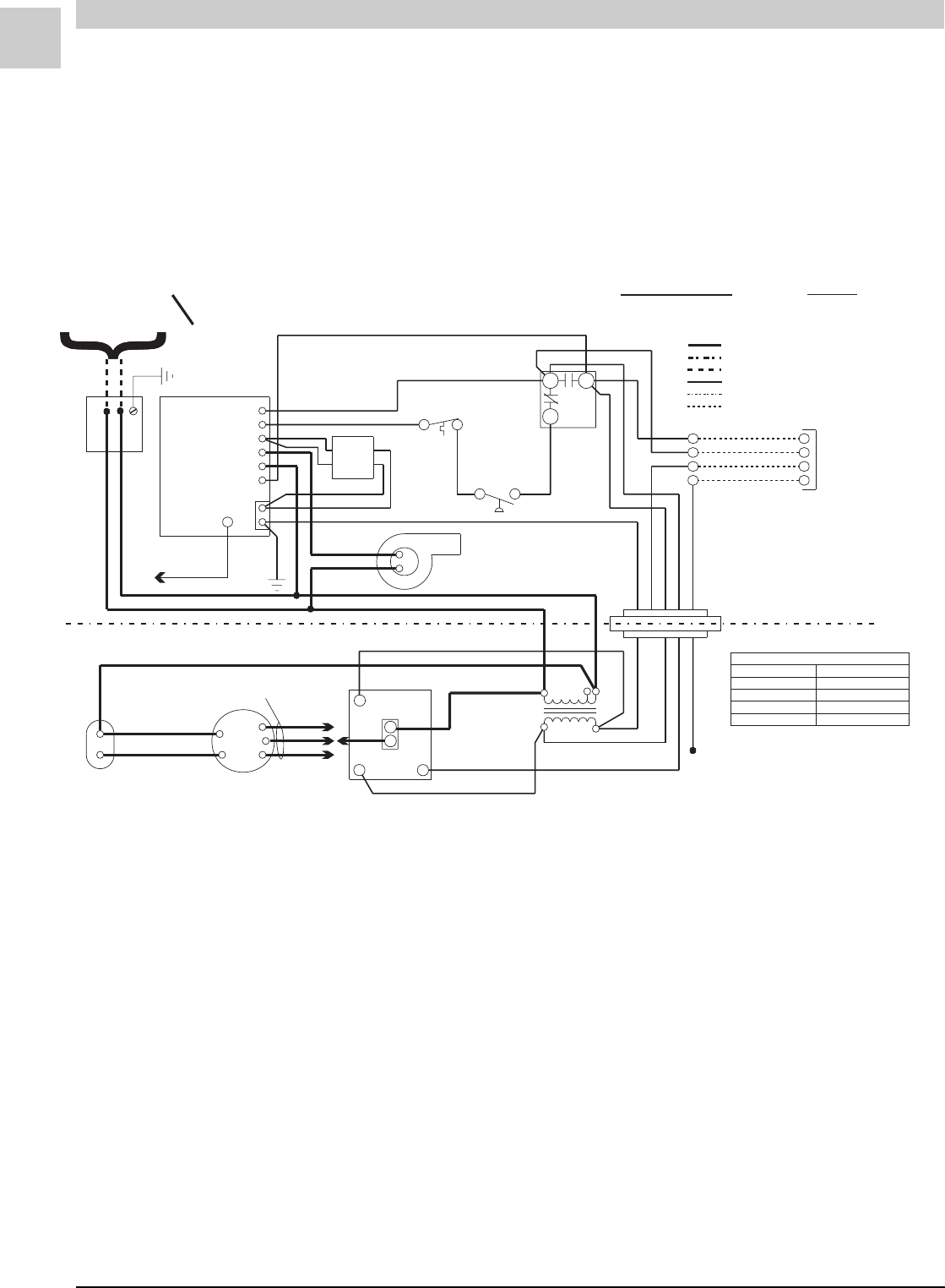
SPECIFICATIONS Magic-Pak: HW/HWC
2-22
SRM-HW/HWC 2/99
#39247D2
HW (Heating Only)
(w/Fenwal Triton 2461D DSI Ignition Control)
CIRCUITS ENERGIZED
OPERATING MODE CIRCUIT
HEATING R-W
LINE VOLTAGE - FACTORY
LINE VOLTAGE - FACTORY (WHEN USED)
LINE VOLTAGE - FIELD
LOW VOLTAGE - FACTORY
LOW VOLTAGE - FIELD
LOW VOLTAGE - FACTORY (WHEN USED)
208/230-1-60
POWER SUPPLY COPPER CONDUCTORS
ONLY
THERMOSTAT
Y
NOTE:
IF ANY OF THE ORIGINAL
WIRES ARE REPLACED,
THE SAME SIZE AND TYPE
WIRE MUST BE USED.
MOTOR SPEED CONNECTIONS
MODELS
26HW
38HW
51HW
64HW
HEATING
LOW (RED)
HIGH (BLACK)
MED (BLUE)
HIGH (BLACK)
PINK
BROWN
WHITE
ORANGE
BLUE
ORANGE
BLUE
BLACK
BLACK
BLACK
BLACK
BLACK
YELLOW
YELLOW
BROWN BLUE
BLACK
RED
RED
WHITE
SEE CHART
FOR WIRING
BLACK
BLACK
WHITE
WHITE
RED
GREEN
RED
RED
WHITE
WHITE
GREEN
BLUE
YELLOW RED
WHITE
GREEN
BLUE
BLUE
TH
P. S W
L1
IND
V1
24VAC
V2
GND
ELECTRODE
CABLE
IGNITION
CONTROL
GAS
VALVE
COMBUSTION
BLOWER
MANUAL
RESET
LIMIT
SWITCH
PRESSURE
SWITCH
CAPACITOR
BLOWER BLOWER
MOTOR
BLOWER
BLOWER
CONTROL
208 240
TRANS-
FORMER
CNO
NC
R
W
Y
G
R
W
G
RW
C
L1
H
FIGURE 2-4 Connection Diagram

Service Reference Manual SEQUENCE OF OPERATIONS
2-23
SRM-HW/HWC 2/99
Simplified Sequence - HW (w/Fenwal 2461D Board)
Refer to Figure 2-4
CALL FOR HEAT
1. A call for heat closes the circuit between R and W
on the thermostat. This sends a 24-volt signal to the
white wire on the unit.
2. The 24-volt signal energizes terminal TH on the
ignition control and the W terminal on the blower
control board.
3. With the TH terminal energized, the ignition control
closes an internal relay. This sends line voltage
from terminal IND to the induced draft blower,
starting the inducer.
4. After a pre-purge cycle of approximately 30 sec-
onds, the ignition control makes a trial for ignition.
Terminal V1 energizes at this time, opening the gas
valve. The ignition control initiates a spark at the
burner to light the main burners.
5. The trial for ignition lasts seven seconds, at which
time the ignition control stops sparking. The ignition
control looks at the flame sense to determine if the
main burners have ignited. If flame sense is not
proven, the ignition control goes through another
pre-purge cycle (approximately 30 seconds) and
makes another trial for ignition. It does this three
times. If the three trials for ignition fail, the ignition
control locks out for approximately 60 minutes.
After 60 minutes, the ignition control again makes
three trials for ignition. This continues as long as
there is a call for heat from the thermostat.
6. When W energizes, the blower control board starts
a countdown to fan “on”. Approximately 60 seconds
after the thermostat initiates a call for heat, the
circulating air blower starts.
7. The unit continues to operate as long as there is a
call for heat from the thermostat.
8. When the heat call is satisfied, the circuit between R
and W is interrupted. With the white wire de-
energized, the ignition control interrupts the 24-volt
signal to the gas valve. This closes the gas valve
immediately and opens the internal relay that de-
energizes terminal IND. The induced draft blower
shut downs several seconds later.
9. The W terminal on the blower control board de-
energizes. This causes the blower control board to
start a countdown to blower “off”. Approximately 90
seconds later, the circulating air blower shuts down.
This completes the heating cycle.
Detailed Sequence follows

SPECIFICATIONS Magic-Pak: HW/HWC
2-24
SRM-HW/HWC 2/99
Detailed Sequence - HW
(w/Fenwal Triton 2461D Ignition Control)
Refer to Figure 2-4
POWER
Line Voltage
When the service disconnect switch is closed, power is
sent to the unit (unit in standby, no signal from thermo-
stat). Power (208 - 230 volts A/C) is supplied to the two
black wires located in the junction block on top of the
unit.
Line voltage will be present at the following locations:
First black wire
1. L-1 on the ignition control
2. Terminal on the transformer marked 208V or
240V (whichever is being used)
3. Common terminal on the blower capacitor
Second black wire
1. Supplies power to the one side of the induced
draft blower
2. Common terminal on the transformer
3. L terminal on the blower control board
Low Voltage (24 VAC)
With the unit at rest (no call from the thermostat), 24
volts A/C will be found at the following points:
1. Red wire exiting the top of the unit
2. Terminal marked NO on the limit switch
2. Terminal marked 24VAC on the ignition control
3. Terminal R on the blower control board
CALL FOR HEAT
Line Voltage
The thermostat closes the circuit between R and W.
The following is the sequence of operation for the line
voltage side of the unit:
1. Terminal TH on the ignition control energizes,
causing a relay in the ignition control to close.
This sends line voltage to terminal IND on the
ignition control, causing the induced draft
blower to start.
2. When W is energized, a 24-volt signal is also sent
to the W terminal on the blower control board.
Approximately 60 seconds after W terminal ener-
gizes, the timer on the blower control board
closes the heat speed relay on the board. This
sends line voltage to the H terminal on the blower
control board, which starts the circulating air
blower.
3. The induced draft blower and the circulating air
blower continue to operate as long as W is ener-
gized.
4. When W de-energizes, a relay in the ignition
control opens. Terminal IND de-energizes and the
induced draft blower shuts down. Approximately
90 seconds later, the circulating air blower also
shuts down.
Low Voltage
The following is the sequence of operation for the low
voltage side of the unit on a heat call:
1. A call for heat closes the circuit in the thermostat
between R and W, sending a 24-volt signal to the
white wire on the unit.
2. The white wire goes to the C terminal on the limit
switch.
3. The 24-volt signal is sent from the C terminal
(brown wire) on the limit switch to terminal TH on
the ignition control. This causes the ignition
control to close the line voltage relay, starting the
induced draft blower. When the induced draft
blower comes up to speed and creates enough
negative pressure, the pressure switch closes.
4. With the pressure switch closed, the 24-volt signal
goes to the rollout switch located over the burners.
5. The 24-volt signal from the rollout switch goes to
the terminal marked P.SW on the ignition control,
causing the ignition control to make a trial for
ignition (sparking). Terminal V1 on the ignition
control also energizes at this time, causing the gas
valve to open.
6. At the same time that the C terminal on the limit
switch energizes, a 24-volt signal is also sent to the
W terminal on the blower control board. This
starts the timer on the blower control board.
Approximately 30 seconds after the main burners
ignite, the blower control board closes a relay;
this sends line voltage to the circulating air
blower, starting the blower.
7. As long as W (white wire) is energized, the unit
continues to operate.
8. When the heat call is satisfied, the circuit between R
and W is interrupted.

Service Reference Manual SEQUENCE OF OPERATIONS
2-25
SRM-HW/HWC 2/99
9. When W de-energizes, the gas valve immediately
shuts down and the induced draft blower also
stops after several seconds.
10. The blower control board starts a countdown to
blower “off”. Approximately 90 seconds later, the
circulating air blower shuts down.
LIMIT OPENS
If the limit switch opens for any reason during a call for
heat, the following happens:
1. If the limit switch senses that the temperature in
the unit is too high, the circuit between terminals C
and NC on the limit switch opens. This closes the
circuit between terminals C and NO on the limit
switch, interrupting the 24-volt signal to the pres-
sure switch and the rollout switch and causing
terminal P.SW on the ignition control to de-
energize. The gas valve immediately closes, as
there is no longer a 24-volt signal at terminal V1 on
the ignition control. With 24 volts still going to the
blower control board and terminal TH on the
ignition control, the circulating air blower and
induced draft blower continue to run.
2. The circulating air blower and the induced draft
blower continue to run as long as there is a call for
heat from the thermostat or the limit switch
remains open.
3. When the limit switch senses that the temperature
in the unit is low enough, the circuit between C and
NO opens and the circuit between C and NC
closes.
4. With the limit switch closed, the unit again makes
a trial for ignition and returns to normal operation.
PRESSURE SWITCH OPENS (BLOCKED FLUE)
1. If blockage of the flue occurs, the negative pressure
in the induced draft blower is reduced. At the set
point of the pressure switch, the contacts open.
This interrupts the 24-volt signal coming from
terminal NC on the limit switch. Terminal P.SW on
the ignition control de-energizes, as does terminal
V1. With loss of the 24-volt signal to the gas valve,
the valve closes immediately.
2. Terminals TH on the ignition control and W on the
blower control board remain energized. The
induced draft blower and the circulating air
blower continue to run.
3. When the pressure switch senses that there is
enough negative pressure within the flue, it will
again close the circuit between the limit switch and
terminal P.SW on the ignition control.
4. The unit makes a trial for ignition and returns to
normal operation.
Note: If the P.SW and TH terminals energize at the
same time, the ignition control will not respond.
A pressure switch being stuck closed is an
example of what would cause this to happen.
ROLLOUT SWITCH ACTIVATED
1. If the conditions in the burner compartment cause
the rollout switch to trip, the contacts on the switch
open. This interrupts the 24-volt signal going to
terminal P.SW on the ignition control, causing
terminal V1 on the ignition control to de-energize.
This interrupts the 24-volt signal to the gas valve
and immediately closes it. Since terminal TH on the
ignition control and W on the blower control
board remain energized, the induced draft
blower and the circulating air blower continue to
run.
2. The 24-volt signal to the ignition control can only
be restored if the rollout switch is manually reset.
3. Once the cause of the rollout switch being tripped
has been determined, the switch can be reset.
4. With the rollout switch reset, terminal P.SW on the
ignition control again energizes. The ignition
control makes a trial for ignition and operation
returns to normal.
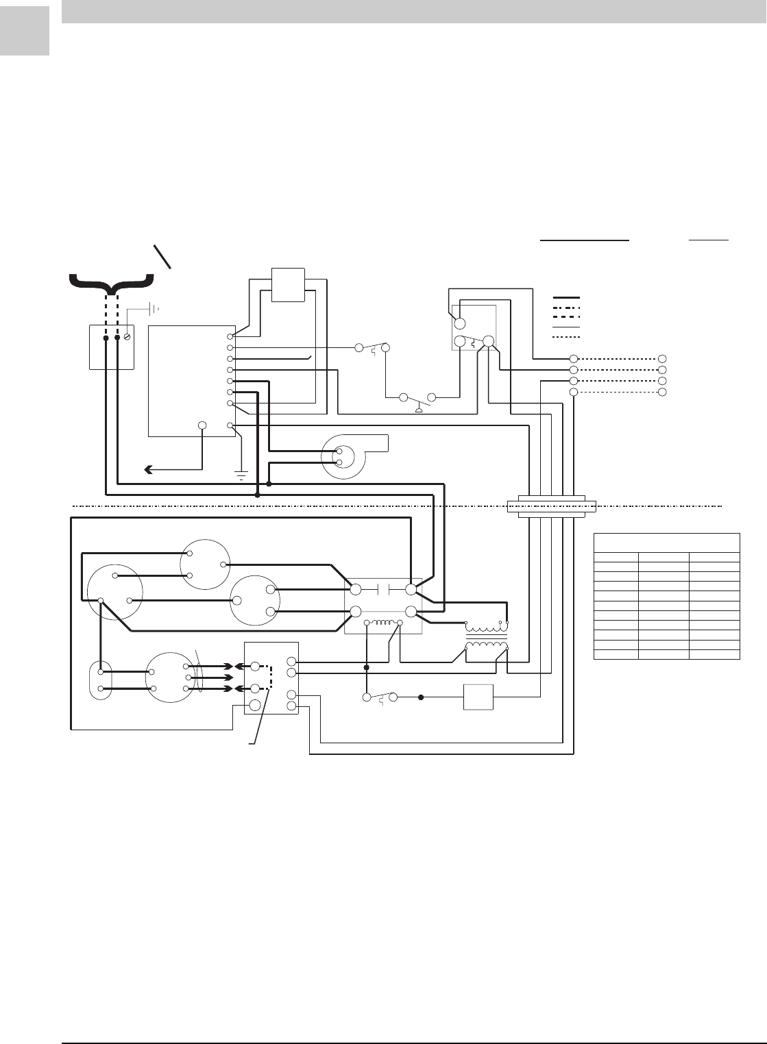
SPECIFICATIONS Magic-Pak: HW/HWC
2-26
SRM-HW/HWC 2/99
#39007D4
FIGURE 2-5 Connection Diagram
HWC122, 182, 242, 302
(w/Fenwal 05-29 Ignition Contr(w/Fenwal 05-29 Ignition Contr
(w/Fenwal 05-29 Ignition Contr(w/Fenwal 05-29 Ignition Contr
(w/Fenwal 05-29 Ignition Control)ol)
ol)ol)
ol)
208/230-1-60
POWER SUPPLY COPPER CONDUCTORS
ONLY
GAS
VALVE
LINE VOLTAGE - FACTORY
LINE VOLTAGE - FACTORY (WHEN USED)
LINE VOLTAGE - FIELD
LOW VOLTAGE - FACTORY
LOW VOLTAGE - FIELD
CIRCUITS ENERGIZED
OPERATING MODE CIRCUIT
HEATING
COOLING
FAN
R-W
R-G-Y
R-G
NOTE:
IF ANY OF THE ORIGINAL
WIRES ARE REPLACED,
THE SAME SIZE AND TYPE
WIRE MUST BE USED.
EVAPORATOR MOTOR
MODELS
SPEED CONNECTIONS
HEATING COOLING
26HWC122
38HWC122
38HWC182
38HWC242
51HWC182
51HWC242
51HWC302
64HWC182
64HWC242
64HWC302
LOW (RED) MED (BLUE)
HIGH (BLK) MED (BLUE)
LOW (RED) LOW (RED)
LOW (RED)
LOW (RED)
LOW (RED)
MED (BLUE)
MED (BLUE)
MED (BLUE)
MED (BLUE) MED (BLUE)
MED (BLUE)
HIGH (BLK)
HIGH (BLK) HIGH (BLK)
HIGH (BLK)
HIGH (BLK)
*
*
*
*
JUMPER REQUIRED
FOR WIRING
SEE TABLE
SEE TABLE
MOTOR
BLOWER
CAPACITY BLOWER
IGNITION
CONTROL
BLACK
BLACK
P. S W
V1
IND
L1
V2
S1
TS
ELECTRODE
CABLE
GREEN
RED
BLACK
BLACK
WHITE
GND
FLAME
SENSOR
BLACK
BLACK
COMBUSTION
BLOWER
BROWN
WHITE
ORANGE
ORANGE
BLUE
BLUE
MANUAL
RESET
WHITE
PRESSURE
SWITCH
WHITE
SWITCH
LIMIT
NO
NC
C
RED
WHITE
R
W
Y
G
R
W
Y
G
RED
YELLOW
BLUE
WHITE
GREEN
CONNECTOR
BLOCK
RED
BLUE
BLACK
CONTACTOR
208V 240V
TRANS-
BLACK
BLUE
RED
YEL YEL
TIME DELAY
(IF USED)
BLK
BLK
YEL
BLUE
FORMER
WHITE
GREEN
COMP T’STAT
(IF USED)
T1
T2
L1
L2
C
R
W
G
C
L1
H
BLK
BLACK
BLACK
BLACK
RED
BLOWER
CONTROL
CONDENSER FAN
FAN
COM
HERM
CAPACITOR-RUN
S
C
R
VIOLET
BROWN
YELLOW
RED
RED
YEL
BROWN
BLK
BLUE
RED
Note: On units that are equipped with a low ambient switch (designated with an “SA” in the model
number), sequence of operation during cooling call is modified when outdoor temperatures fall
below the normal operating range. For more information on the low ambient switch equipped
version of this unit, see the section beginning on page 2-38.

Service Reference Manual SEQUENCE OF OPERATIONS
2-27
SRM-HW/HWC 2/99
Simplified Sequence - HWC122, 182, 242, 302
(w/Fenwal 05-29 Ignition Control)
Refer to Figure 2-5
CALL FOR COOLING
1. A call for cooling closes the circuit from R to Y and
G.
2. A 24-volt signal is sent to blower control board
terminal G and to the compressor contactor. The
contactor closes, sending line voltage to the com-
pressor and the outdoor condenser fan.
3. With a 24-volt signal at terminal G on the blower
control board, the circulating air blower starts in
cooling speed 15 seconds later (see note below).
4. When the cooling call is completed, G and Y de-
energize. The contactor opens immediately, stop-
ping the compressor and the outdoor cooling fan.
When G de-energizes, the timer to turn off the
circulating air blower starts. The blower turns off
after 90 seconds (see note below).
FAN ON
1. When the thermostat switch is moved to the “FAN
ON” position, the circuit between R and G closes.
2. The 24-volt signal from G goes to the blower control
board which starts the timer.
3. Fifteen seconds after terminal G on the blower
control board energizes (or immediately after - see
note below), the circulating air blower starts.
4. When terminal G on the blower control board de-
energizes, the timer to turn off the circulating air
blower starts. The blower turns off after 90 seconds
(see note below).
Note: Heatcraft blower control boards have a G “on”
delay of 15 seconds and an “off” delay of 90
seconds. Tridelta blower control boards have no
“on” time delay and a 60 -130 second “off” delay.
CALL FOR HEAT
1. The thermostat energizes the R-W circuit, sending a
24-volt signal to the W wire at the unit.
2. The 24-volt signal is sent to the ignition control,
closing the combustion blower relay and causing the
combustion blower to run.
3. The 24-volt signal is also sent to the blower control
board, starting a 30-second circulation air blower
“on” delay.
4. As the combustion blower reaches full speed, it
closes the pressure switch.
5. A 24-volt signal is sent from the pressure switch to
the ignition control. Following a 30-second pre-
purge delay, this signal energizes the spark termi-
nal.
6. The gas valve solenoid energizes at the same time
as the spark terminal, causing the gas valve to open
and the burners to light.
7. The spark ignitor continues to spark for approxi-
mately six seconds or until flame is sensed by the
flame sensor electrode.
8. The unit will operate normally until the R-W circuit is
de-energized by the thermostat, interrupting the 24-
volt signal to the unit.
9. When the signal is interrupted, the gas valve de-
energizes and closes immediately.
10. The combustion blower relay de-energizes several
seconds later, causing the combustion blower to
stop.
11. The blower control board starts a 90-second
circulating air blower “off” delay.
12. Following the 90-second delay, the circulating air
blower stops.
FLAME SENSE
1. After the spark electrode has lit the main burners,
the ignition control waits approximately six seconds
for a flame sense signal.
2. If a flame sense signal is not received after approxi-
mately six seconds, the ignition control de-ener-
gizes the spark terminal and gas valve.
3. The thermostat R-W circuit sends a 24-volt signal to
the blower control board, starting the circulating air
blower (after a 30-second delay).
4. The unit initiates three trials for ignition (flame
sense) before system lockout.
Detailed Sequence follows

SPECIFICATIONS Magic-Pak: HW/HWC
2-28
SRM-HW/HWC 2/99
Detailed Sequence - HWC122, 182, 242, 302
(w/Fenwal 05-29 Ignition Control)
Refer to Figure 2-5
POWER
Line Voltage
When the service disconnect switch is closed, power is
sent to the unit (unit in standby, no signal from the
thermostat). Power (208 - 230 volts A/C) is supplied
to both black wires located in the junction block on top
of the unit.
Line voltage will be present at the following locations:
First black wire
1. L-1 on the ignition module
2. L-1 on the contactor
3. L-1 on the blower control board
4. Terminal on the transformer marked 208V or
240V (whichever is being used)
Second black wire
1. Supplies power to the induced draft blower
2. L-2 on the contactor
3. Common terminal on the transformer
4. T-2 on the contactor
5. Red wire on the R terminal of the compressor
6. Red wire to the common terminals on the capaci-
tors
Low Voltage (24 VAC)
With the unit at rest (no call from the thermostat), 24
volts A/C will be found at these points:
1. Red wire exiting the top of the unit
2. Terminal marked 24VAC on the ignition control
3. Terminal R on the blower control board
CALL FOR HEAT
Line Voltage
The thermostat closes the circuit between R and W.
The following is the sequence of operation for the line
voltage side of the unit:
1. Terminal TS (24-volt) energizes on the ignition
control, causing a relay in the ignition control to
close. This sends line voltage to the terminal
marked IND, causing the induced draft blower to
start.
2. When W is energized, a 24-volt signal is also sent to
the W terminal on the blower control board. The
24-volt signal starts the timer on the blower con-
trol board. After 60 seconds, the heat speed relay
on the blower control board closes. This sends
line voltage from the terminal marked HEAT to the
circulating air blower, starting the blower. The
induced draft blower and the circulating air
blower continue to operate until the heat call is
satisfied, interrupting the circuit between R and W.
The W terminal de-energizes, causing the blower
relay to open approximately 90 seconds later. This
interrupts the line voltage to the circulating air
blower and the blower shuts down.
Low Voltage
1. A call for heat closes the circuit in the thermostat
between R and W, sending a 24-volt signal to the
white wire on the unit.
2. The white wire goes to the C terminal on the limit
switch, ignition control terminal TS and terminal
W on the blower control board.
3. When W energizes, the timer starts a countdown to
circulating air blower “on”. The blower starts in
approximately 60 seconds.
4. The 24-volt signal sent to the TS terminal closes a
relay in the ignition control. This starts the
induced draft blower by energizing terminal IND
on the ignition control.
5. As the induced draft blower comes up to speed
and creates enough negative pressure, the pres-
sure switch closes. The 24-volt signal is sent from
the pressure switch to one side of the Normally
Closed manual reset rollout switch. If the
rollout switch is closed, the 24-volt signal is
passed through the switch to the P.SW terminal on
the ignition control. This initiates a 30-second pre-
purge period.
6. After the 30-second pre-purge period, a trial for
ignition starts by energizing the spark terminal and
the V1 terminal simultaneously. The 24-volt signal
from V1 energizes the gas valve solenoid, causing
it to open. These actions cause the burners to light.
7. After the burners are lit, a flame sense is picked up
by the flame sense rod located at the opposite
end of the burner rack from the spark electrodes.
The flame sense signal is sent to the S1 terminal of
the ignition control. The unit continues to operate
as long as W is energized.
8. When the call for heat is satisfied, the circuit be-
tween R and W is interrupted, de-energizing W.

Service Reference Manual SEQUENCE OF OPERATIONS
2-29
SRM-HW/HWC 2/99
9. With W de-energized, the gas valve closes immedi-
ately and the induced draft blower stops several
seconds later.
10. The blower control board starts a 90-second
circulating air blower “off” delay. Approximately
90 seconds later, the blower stops.
FLAME SENSE
1. During a call for heat, the spark terminal is ener-
gized and the gas valve is opened to light the
burners.
2. The ignition control energizes the spark terminal
and the gas valve for approximately six seconds. If
a flame is not sensed in this time period, the igni-
tion control de-energizes the spark terminal and
the gas valve. This causes the gas valve to close
and the burners to shut off.
3. Since the 24-volt signal has been sent to the
blower control board, the circulating air blower
times “on” in approximately 60 seconds.
4. The induced draft blower continues to run for
approximately 30 seconds, then another trial for
ignition begins.
5. The ignition control runs three trials for ignition. If
a flame is not sensed during these three trials, the
ignition control will lockout.
6. The circulating air blower continues to run until
the R-W circuit at the thermostat is interrupted.
7. The ignition control remains in lockout until 24-volt
power to the ignition control is reset.
LIMIT OPENS
If the limit switch opens for any reason during a call for
heat, the following happens:
1. If the limit switch senses that the temperature in
the unit is too high, the contacts between terminals
C and NC on the limit switch open and the con-
tacts between C and NO close. This interrupts the
24-volt signal to the pressure switch and also de-
energizes terminal P.SW on the ignition control.
The gas valve closes immediately, as the 24-volt
signal to terminal P.SW is no longer present. The
induced draft blower and the circulating air
blower continue to run. Power to blower control
board terminal W is maintained. The blower
continues to run until the limit switch closes or the
heat call at the thermostat is satisfied.
2. When the limit switch senses that the tempera-
tures in the unit are normal, the contacts between
terminals C and NO open, the contacts between
terminals C and NC close and the operation of the
unit returns to normal.
PRESSURE SWITCH OPENS (BLOCKED FLUE)
1. If blockage of the flue occurs, negative pressure in
the induced draft blower is reduced. At the set
point of the pressure switch, the contacts open.
This interrupts the 24-volt signal to terminal P.SW
on the ignition control. The gas valve closes
immediately, as a relay in the ignition control
opens and interrupts the signal to terminal V2 of the
ignition control.
2. Terminal W on the blower control board stays
energized and the circulating air blower contin-
ues to run. If negative pressure is restored, the
pressure switch closes and sends a 24-volt signal
to the P.SW terminal on the ignition control. The
ignition control makes a trial for ignition again and
the operation returns to normal.
ROLLOUT SWITCH ACTIVATED
1. If conditions in the burner compartment cause the
rollout switch to trip, the contacts on the switch
open, interrupting the 24-volt signal going to termi-
nal P.SW on the ignition control. This causes the
ignition control to de-energize terminal V1,
interrupting the 24-volt signal to the gas valve and
immediately closing it.
2. The reason the rollout switch was tripped must be
determined before any corrective action is taken.
3. The signal to terminal P.SW can only be restored if
the rollout switch is reset, which can only be done
manually. The W terminal on the blower control
board remains energized and the circulating air
blower continues to operate. Once the rollout
switch is reset, the operation of the unit returns to
normal.
CALL FOR COOLING
Line Voltage
On a call for cooling, the thermostat closes the circuit
between Y, G and R.
1. With Y energized, the contactor closes. This
sends line voltage to compressor terminal C,
causing the compressor to start. The outdoor fan
also starts, drawing air through the outdoor coil.
2. Terminal G on the blower control board also
energizes at same time as Y. This starts the timer
on the blower control board. Approximately 15
seconds later (or immediately - see note on page 2-
30), the terminal marked COOL energizes. This
sends line voltage to the circulating air blower,
starting the blower.

SPECIFICATIONS Magic-Pak: HW/HWC
2-30
SRM-HW/HWC 2/99
3. The unit continues cooling as long as both Y and G
are energized. When the cooling call is satisfied,
the circuit between Y, G and R is interrupted. The
contactor immediately opens, interrupting power to
the compressor and the outdoor cooling fan.
4. With the low voltage signal to terminal G on the
blower control board interrupted, the board starts
a countdown to blower “off”. After approximately 90
seconds, the cooling speed relay opens and the
circulating air blower shuts down (see note at the
end of this section).
Low Voltage
1. On a call for cooling, the thermostat closes the
circuit between R and terminals G and Y.
2. The 24-volt signal energizes terminal G on the
blower control board, starting the fan “on” timer.
After approximately 15 seconds, the relay closes
(see note at the end of this section). This sends line
voltage to the COOLING speed terminal on the
board, which starts the circulating air blower.
3. The signal from Y energizes the contactor, starting
the compressor and the outdoor cooling fan.
4. When the cooling call is satisfied, both G and Y de-
energize. The contactor opens immediately,
causing the compressor and the outdoor cooling
fan to stop.
5. The circulating air blower stops approximately 90
seconds after the G terminal on the blower control
board de-energizes (see note at the end of this
section).
FAN ON
Low Voltage
1. When the switch on the thermostat is moved to the
“FAN ON” position, a 24-volt signal is sent to the G
terminal on the blower control board.
2. With G energized, the blower control board starts
a countdown to fan “on”. Approximately 15 seconds
later (or immediately - see note at the end of this
section), the fan starts.
3. The blower control board closes a relay on the
board, sending line voltage to the terminal on the
board marked COOL. This starts the circulating
air blower.
4. When the switch at the thermostat is moved to the
“OFF” position, the 24-volt signal to the blower
control board is interrupted. With no signal at the
G terminal, the blower control board starts a
countdown to fan “off”. Approximately 90 seconds
later, a relay on the blower control board opens
(see note at the end of this section). This interrupts
the power to and stops the circulating air blower.
Note: Heatcraft blower control boards have a G “on”
delay of 15 seconds and an “off” delay of 90
seconds. Tridelta blower control boards have no
“on” time delay and a 60 -130 second “off” delay.

Service Reference Manual SEQUENCE OF OPERATIONS
2-31
SRM-HW/HWC 2/99
BLANK PAGE
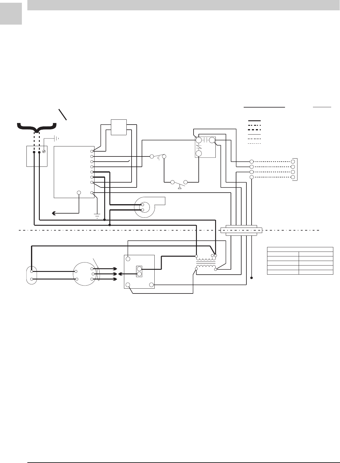
SPECIFICATIONS Magic-Pak: HW/HWC
2-32
SRM-HW/HWC 2/99
#39247D1
HW (Heating Only)
(w/Fenwal 05-29 Ignition Control)
C
CIRCUITS ENERGIZED
OPERATING MODE CIRCUIT
HEATING R-W
LINE VOLTAGE - FACTORY
LINE VOLTAGE - FACTORY (WHEN USED)
LINE VOLTAGE - FIELD
LOW VOLTAGE - FACTORY
LOW VOLTAGE - FIELD
LOW VOLTAGE - FACTORY (WHEN USED)
BROWN
208/230-1-60
POWER SUPPLY COPPER CONDUCTORS
ONLY
NO
NC
MANUAL
RESET
PRESSURE
SWITCH
GAS
VALVE
WHITE
WHITE
FLAME
SENSOR
BLACK
BLACK
BLACK
BLACK
COMBUSTION
BLOWER
ELECTRODE
CABLE
BLACK
BLACK
GREEN
V1
P. S W
S1
TS
IND
L1
V2
GND
RED
IGNITION
CONTROL
LIMIT
SWITCH
ORANGE
ORANGE
BLUE
BLUE
RED
WHITE
WHITE
WHITE
THERMOSTAT
R
W
Y
G
R
W
Y
G
WHITE
RED
GREEN
YELLOW
BLUE
NOTE:
IF ANY OF THE ORIGINAL
WIRES ARE REPLACED,
THE SAME SIZE AND TYPE
WIRE MUST BE USED.
WHITE
RED
GREEN
BLUE
BLACK
208 240
TRANS-
FORMER
WHITE
RED
BLUE
BLOWER
CONTROL
BLOWER
RW
C
L1
H
BLACK
BLUE
RED
MOTOR
BLOWER
SEE CHART
FOR WIRING
YELLOW
YELLOW
BROWN
BLOWER
CAPACITOR
MOTOR SPEED CONNECTIONS
MODELS
26HW
38HW
51HW
64HW
HEATING
LOW (RED)
HIGH (BLACK)
MED (BLUE)
HIGH (BLACK)
FIGURE 2-6 Connection Diagram

Service Reference Manual SEQUENCE OF OPERATIONS
2-33
SRM-HW/HWC 2/99
Simplified Sequence - HW (w/Fenwal 05-29 Board)
Refer to Figure 2-6
CALL FOR HEAT
1. The indoor thermostat calls for heat by energizing
the R-W circuit.
2. This sends a 24-volt signal to the ignition control,
causing the induced draft blower to run.
3. A 24-volt signal is also sent to the blower control
board at this time, starting a 60-second circulating
air blower “on” delay. The circulating air blower
starts 60 seconds after the initial call for heat.
4. The induced draft blower causes the pressure
switch to close which starts a 30-second pre-purge.
After the pre-purge period, the burners ignite.
5. The unit operates in the heating mode until the
indoor thermostat setting is reached and the R-W
circuit is interrupted.
6. When the R-W circuit is interrupted, the 24-volt
signal to the ignition control and the signal to the
blower control board are interrupted.
7. The induced draft blower stops within several
seconds and a 90-second circulating air blower “off”
delay starts. Following the delay period, the circu-
lating air blower shuts off.
Detailed Sequence follows

SPECIFICATIONS Magic-Pak: HW/HWC
2-34
SRM-HW/HWC 2/99
Detailed Sequence - HW
(w/Fenwal 05-29 Ignition Control)
Refer to Figure 2-6
POWER
Line Voltage
When the service disconnect switch is closed, power is
sent to the unit (unit in standby, no signal from the
thermostat). Power (208 - 230 volts A/C) is supplied
to both black wires located in the junction block on top
of the unit.
Line voltage will be present at the following locations:
First black wire
1. L-1 on the ignition module
2. Terminal on the transformer marked 208V or
240V (whichever is being used)
3. Circulating air blower capacitor terminal
Second black wire
1. Supplies power to the induced draft blower
2. Common terminal on the transformer
3. Terminal L-1 on the blower control board
Low Voltage (24 VAC)
With the unit at rest (no call from the thermostat), 24
volts A/C will be found at these points:
1. Red wire exiting the top of the unit
2. Terminal R on the blower control board
3. Terminal NO on the limit switch
4. Terminal on the transformer marked 24V
CALL FOR HEAT
Line Voltage
The thermostat closes the circuit between R and W.
The following is the sequence of operation for the line
voltage side of the unit:
1. Terminal TS (24-volt) energizes on the ignition
control, causing a relay in the ignition control to
close. This sends line voltage to the terminal
marked IND, causing the induced draft blower to
start.
2. When W is energized, a 24-volt signal is also sent
to the W terminal on the blower control board.
The 24-volt signal starts the timer on the blower
control board. After 60 seconds, the relay on the
blower control board closes. This sends line
voltage from the terminal marked L-1 to the terminal
marked H on the blower control board, starting
the circulating air blower. The induced draft
blower and the circulating air blower continue to
operate until the heat call is satisfied, interrupting
the circuit between R and W. The ignition control
de-energizes the induced draft blower relay,
interrupting L-1 power to the induced draft blower.
The induced draft blower stops several seconds
later. The W terminal on the blower control board
de-energizes, starting a 90-second blower “off”
delay. This interrupts the line voltage to the circu-
lating air blower and after 90 seconds, the blower
shuts down.
Low Voltage
1. A call for heat closes the circuit in the thermostat
between R and W, sending a 24-volt signal to the
white wire on the unit.
2. The white wire goes to the C terminal on the limit
switch, ignition control terminal TS and terminal
W on the blower control board.
3. When W energizes, the timer starts a countdown to
circulating air blower “on”. The blower starts in
approximately 60 seconds.
4. The 24-volt signal sent to the TS terminal closes a
relay in the ignition control. This starts the
induced draft blower by energizing terminal IND
on the ignition control.
5. As the induced draft blower comes up to speed
and creates enough negative pressure, the pres-
sure switch closes. The 24-volt signal is sent from
the pressure switch to one side of the Normally
Closed manual reset rollout switch. If the
rollout switch is closed, the 24-volt signal is
passed through the switch to the P.SW terminal on
the ignition control. This initiates a 30-second
pre-purge period.
6. After the 30-second pre-purge period, a trial for
ignition starts by energizing the spark terminal and
the V1 terminal simultaneously. The 24-volt signal
from V1 energizes the gas valve solenoid, causing
it to open. These actions cause the burners to light.
7. After the burners are lit, a flame sense is picked up
by the flame sense rod located at the opposite
end of the burner rack from the spark electrodes.
The flame sense signal is sent to the S1 terminal of
the ignition control. The unit continues to operate
as long as W is energized.

Service Reference Manual SEQUENCE OF OPERATIONS
2-35
SRM-HW/HWC 2/99
8. When the call for heat is satisfied, the circuit be-
tween R and W is interrupted, de-energizing W.
9. With W de-energized, the gas valve closes immedi-
ately and the induced draft blower stops several
seconds later.
10. The blower control board starts a 90-second
blower “off” delay. Approximately 90 seconds later,
the blower stops.
FLAME SENSE
1. During a call for heat, the spark terminal is ener-
gized and the gas valve is opened to light the
burners.
2. The ignition control energizes the spark terminal
and the gas valve for approximately six seconds. If
a flame is not sensed in this time period, the igni-
tion control de-energizes the spark terminal and
the gas valve. This causes the gas valve to close
and the burners to shut off.
3. Since the 24-volt signal has been sent to the
blower control board, the circulating air blower
times on in approximately 60 seconds.
4. The induced draft blower continues to run for
approximately 30 seconds, then another trial for
ignition begins.
5. The ignition control runs three trials for ignition. If
a flame is not sensed during these three trials, the
ignition control will lockout.
6. The circulating air blower continues to run until
the R-W circuit at the thermostat is interrupted.
7. The ignition control remains in lockout until 24-volt
power to the ignition control is reset.
LIMIT OPENS
If the limit switch opens for any reason during a call for
heat, the following happens:
1. If the limit switch senses that the temperature in
the unit is too high, the contacts between terminals
C and NC on the limit switch open and the con-
tacts between C and NO close. This interrupts the
24-volt signal to the pressure switch and also de-
energizes terminal P.SW on the ignition control.
The gas valve closes immediately, as the 24-volt
signal to terminal P.SW is no longer present. The
induced draft blower and the circulating air
blower continue to run. Power to blower control
board terminal W is maintained. The blower
continues to run until the limit switch closes or the
heat call at the thermostat is satisfied.
2. When the limit switch senses that the tempera-
tures in the unit are normal, the contacts between
terminals C and NO open, the contacts between
terminals C and NC close and the operation of the
unit returns to normal.
PRESSURE SWITCH OPENS (BLOCKED FLUE)
1. If blockage of the flue occurs, negative pressure in
the induced draft blower is reduced. At the set
point of the pressure switch, the contacts open.
This interrupts the 24-volt signal to terminal P.SW
on the ignition control. The gas valve closes
immediately, as a relay in the ignition control
opens and interrupts the signal to terminal V2 of the
ignition control.
2. Terminal W on the blower control board stays
energized and the circulating air blower contin-
ues to run. If negative pressure is restored, the
pressure switch closes and sends a 24-volt signal
to the P.SW terminal on the ignition control. The
ignition control makes a trial for ignition again and
the operation returns to normal.
ROLLOUT SWITCH ACTIVATED
1. If conditions in the burner compartment cause the
rollout switch to trip, the contacts on the switch
open, interrupting the 24-volt signal going to termi-
nal P.SW on the ignition control. This causes the
ignition control to de-energize terminal V1,
interrupting the 24-volt signal to the gas valve and
immediately closing it.
2. The reason the rollout switch was tripped must be
determined before any corrective action is taken.
3. The signal to terminal P.SW can only be restored if
the rollout switch is reset, which can only be done
manually. The W terminal on the blower control
board remains energized and the circulating air
blower continues to operate. Once the rollout
switch is reset, the operation of the unit returns to
normal.
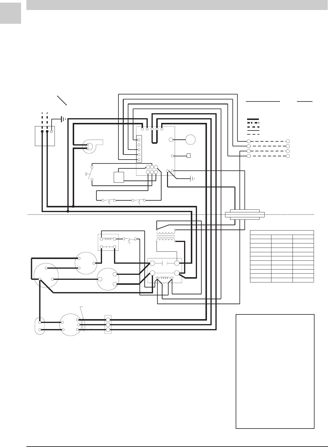
SPECIFICATIONS Magic-Pak: HW/HWC
2-36
SRM-HW/HWC 2/99
#45005-2
GREEN
BLACK
BLK
M
ORANGE
VIOLET
RED
BLUE
WHITE
RED
BLACK
BLUE
YELLOW
WHITE
GREEN
RED
FLAME ROD
ELECTRODE
456
3
2
1
RGWCY
BLACK BLACK
GAS
VALVE
MANUAL RESET
LIMIT SWITCH
COMBUSTION
BLOWER
BLUE
YELLOW
RED
YELLOW
208 V
RED
BLUE
240 V
CAPACITOR
BLOWER
208/230-1-60
POWER SUPPLY COPPER CONDUCTORS
ONLY
}
THERMOSTAT
}
T2
T1
L2
L1
JUMPER REQUIRED
*
*
*
*
HIGH(BLACK)HIGH(BLACK)
HIGH(BLACK)MED (BLUE)
MED (BLUE)HIGH(BLACK)
MED (BLUE)MED (BLUE)
MED (BLUE)LOW (RED)
LOW (RED)HIGH(BLACK)
LOW (RED)MED (BLUE)
LOW (RED)LOW (RED)
MED (BLUE)HIGH(BLACK)
MED (BLUE)LOW (RED)
26HWC123SA
COOLING
HEATINGMODELS
EVAP. MOTOR SPEED CONNECTIONS
BLACK
BLACK
RED
BLACK
BLACK
RED
RED
YELLOW
BLUE
BLACK
VIOLET
YELLOWYELLOW
RED
BLUE
BLACK
BROWN
BROWN
CONNECTION DIAGRAMCONNECTION DIAGRAM
W
Y
G
R
W
Y
G
R
GND
24VAC
UNUSED
HEAT
COOL
L1
CNB
L
H
R
C
S
FAN
COM
HERM
SEE
CHART
FOR WIRING
PRESSURE
SWITCH
AUTO RESET
LIMIT SWITCH
IGNITION
CONTROL
CONTACTOR
BLOWER
MOTOR
CAPACITOR-RUN
CONDENSER FAN
COMP
CONNECTOR
BLOCK
YELLOW
BLACK
FAN RELAY
FAN CONTROL
TERMINAL
BLOCK
CIRCUITS ENERGIZED
OPERATING MODE CIRCUITOPERATING MODE CIRCUIT
HEATING R-W
COOLING R-G-Y
FAN R-G
LINE VOLTAGE-FACTORY
LINE VOLTAGE-FACTORY WHEN USED
LINE VOLTAGE-FIELD
LOW VOLTAGE-FACTORY
LOW VOLTAGE-FIELD
VIOLET
NOTE:
IF ANY OF THE ORIGINAL
WIRES ARE REPLACED, THE
SAME SIZE AND TYPE WIRESAME SIZE AND TYPE WIRE
MUST BE USED.
BLK 38HWC123SA38HWC123SA
64HWC303SA
38HWC183SA
51HWC183SA51HWC183SA
64HWC183SA64HWC183SA
38HWC243SA
51HWC243SA
64HWC243SA
51HWC303SA
BLACK
(WHEN USED)(WHEN USED)
RED
TRANSFORMER
ORANGE
ORANGE
DIAGNOSTICS
The following blower/ignition control board
LED codes will indicate normal or abnormal
operations:
SLOW FLASH Normal Operation, No
Call for Heat
FAST FLASH Normal Operation, Call for
Heat
2 FLASH System Lockout - Failed to
Detect or Sustain Flame
3 FLASH Pressure Switch Open or
Closed
4 FLASH High Limit or Rollout
Switch Open
5 FLASH Flame Sensed and Gas
Valve Not Energized
STEADY Internal Failure
(Micro-controller Failure;
Self-check)
HWC123, 183, 243, 303 Low Ambient
(w/United Technologies 1097 Spark Ignition System)
FIGURE 2-7 Connection Diagram

Service Reference Manual SEQUENCE OF OPERATIONS
2-37
SRM-HW/HWC 2/99
HWC123,183, 243, 303
Low Ambient Model
Refer to Figure 2-7
The low ambient switch is designed to allow the opera-
tion of the air conditioning unit below the normal operat-
ing range. On units equipped with this switch, sequence
of operation during a cooling call is modified when
outdoor temperatures fall below the normal operating
range.
The switch will interrupt the operation of the outdoor
cooling fan when the temperature of the liquid line
coming in from the outdoor coil falls below 55° F. When
the temperature of the liquid line rises to 95° F, the
switch will close and the outdoor fan will resume opera-
tion.
The low ambient switch does not affect any other facet
of the operation of the unit.
To see simplified and detailed sequences of operation
for the HWC123, 183, 243, 303 models, refer to pages
2-5 to 2-9.
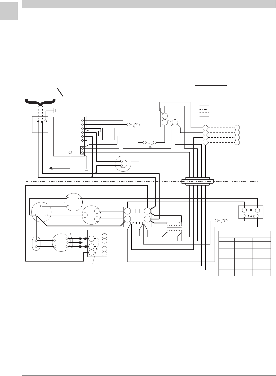
SPECIFICATIONS Magic-Pak: HW/HWC
2-38
SRM-HW/HWC 2/99
#44358-2
HWC122, 182, 242, 302 Low Ambient
LINE VOLTAGE - FACTORY
LINE VOLTAGE - FACTORY (WHEN USED)
LINE VOLTAGE - FIELD
LOW VOLTAGE - FACTORY
LOW VOLTAGE - FIELD
CIRCUITS ENERGIZED
OPERATING MODE CIRCUIT
HEATING
COOLING
FAN
R-W
R-G-Y
R-G
208/230-1-60
POWER SUPPLY COPPER CONDUCTORS
ONLY
BLACK
BLACK
PINK
IGNITION
CONTROL TH
P. S W
VI
L1
IND
24VAC
V2
GND
ELECTRODE
CABLE
WHITE
ORN
ORN
BLUE BROWN
BLUE
BLACK
BLACK
GREEN
RED
BLACK
BLACK
GAS
VALVE
COMBUSTION
BLOWER
MANUAL
RESET
WHITE
LIMIT
SWITCH
WHITE
PRESSURE
SWITCH
NO
NC C
RED
WHITE
Y
R
W
G
THERMOSTAT
Y
R
W
G
WHITE
RED
GREEN
BLUE
YELLOW
NOTE:
IF ANY OF THE ORIGINAL
WIRES ARE REPLACED,
THE SAME SIZE AND TYPE
WIRE MUST BE USED.
BLACK
CONDENSER FAN
BROWN
VIOLET
CAPACITOR-RUN
FAN
HERM
COM YELLOW
RED
R
C
S
RED
YEL
BRN
CAPACITOR
BLOWER BLOWER
MOTOR
SEE TABLE
FOR WIRING
SEE TABLE
BLACK
BLK
RED
BLU
BLUE
BLACK
RED
CC
R
W
G
H
L1
T1
T2
L1
L2
CONTACTOR
BLUE
RED
YELLOW
BLACK
BLACK 208V 240V
24V
TRANS-
FORMER
GREEN
WHITE
BLUE
RED
YELLOW
EVAPORATOR MOTOR
MODELS
SPEED CONNECTIONS
HEATING COOLING
26HWC122
38HWC122
38HWC182
38HWC242
51HWC182
51HWC242
51HWC302
64HWC182
64HWC242
64HWC302
LOW (RED) MED (BLUE)
HIGH (BLK) MED (BLUE)
LOW (RED) LOW (RED)
LOW (RED)
LOW (RED)
LOW (RED)
MED (BLUE)
MED (BLUE)
MED (BLUE)
MED (BLUE) MED (BLUE)
MED (BLUE)
HIGH (BLK)
HIGH (BLK) HIGH (BLK)
HIGH (BLK)
HIGH (BLK)
*
*
*
*JUMPER REQUIRED
BLACK
BLACK
13
FAN
RELAY
FAN
CONTROL
CONNECTOR
BLOCK
BLACK
BLACK
FIGURE 2-8 Connection Diagram

Service Reference Manual SEQUENCE OF OPERATIONS
2-39
SRM-HW/HWC 2/99
The low ambient switch is designed to allow the opera-
tion of the air conditioning unit below the normal operat-
ing range. On units equipped with this switch, sequence
of operation during a cooling call is modified when
outdoor temperatures fall below the normal operating
range.
The switch will interrupt the operation of the outdoor
cooling fan when the temperature of the liquid line
coming in from the outdoor coil falls below 55° F. When
the temperature of the liquid line rises to 95° F, the
switch will close and the outdoor fan will resume opera-
tion.
The low ambient switch does not affect any other facet
of the operation of the unit.
To see simplified and detailed sequences of operation
for the HWC122, 182, 242, 302 models equipped with
the Fenwal Triton 2461D DSI Ignition Control, refer to
pages 2-17 to 2-20.
To see simplified and detailed sequences of operation
for the HWC122, 182, 242, 302 models equipped with
the Fenwal 05-29 Ignition Control, refer to pages 2-27 to
2-30.
HWC122,182, 242, 302
Low Ambient Model
Refer to Figure 2-8

Service Reference Manual UNIT TEAR DOWN
3-1
SRM-HW/HWC 8/99
Section 3 - Unit Tear Down
Heating Section
Heat Exchanger Removal ............................ 3-2
Induced Draft Blower Removal ..................... 3-2
Cooling Section
Chassis Removal ........................................ 3-4
Evaporator Blower Assembly Removal .......... 3-6

3-2
UNIT TEAR DOWN Magic-Pak: HW/HWC
SRM-HW/HWC 8/99
UNIT TEAR DOWN
HWC units are comprised of two major sections.
The heating section is located in the top half of the unit. It contains the
heat exchanger and the majority of the components associated with the
heating function: controls, burners, switches, etc.... The total heating
section is not removable as a complete unit. The heat exchanger may be
removed separately for service (see below).
The cooling section is located in the lower half of the unit. It contains
the compressor, coils and motors that make up the refrigeration system.
The cooling section is referred to as the “chassis” of the cooling system.
The chassis is removable as a complete unit. Removal of the chassis
allows service to be performed away from the job site, thus allowing a
spare chassis to be installed to reduce downtime at a residence. Bench
tests may be performed on chassis. See the Performance Test section
beginning on page 9-11 for chassis performance data of both bench
tested and installed units.
Heating Section
Heat Exchanger Removal:
The heat exchanger may be removed from the unit through the front side.
Refer to the following directions and Figure 3-1.
To remove the heat exchanger:
1. Disconnect all power to the unit.
2. Shut off and disconnect the gas supply.
3. Open the burner access panel.
4. Remove the burner tray and the gas valve.
5. Remove the front heat section panel.
6. Remove the vestibule panel.
7. Remove the heat exchanger.
Induced Draft (Combustion) Blower Removal:
Refer to the following directions and Figure 3-1.
To remove the induced draft blower:
1. Disconnect all power to the unit.
2. Shut off and disconnect the gas supply.
3. Remove the plate mounting screws.
4. Slide the induced draft blower out.
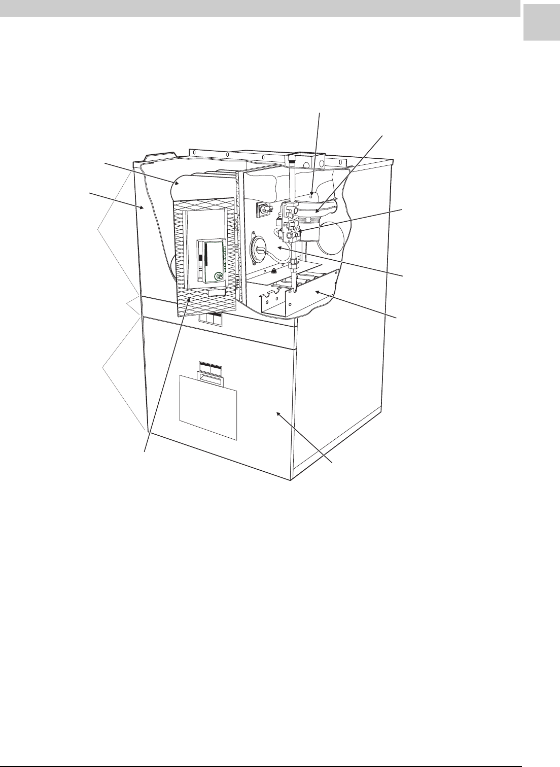
Service Reference Manual UNIT TEAR DOWN
3-3
SRM-HW/HWC 8/99
Figure 3-1
INDUCED DRAFT BLOWER/
COMBUSTION BLOWER
HEATING SECTION
CONTROL SECTION
COOLING SECTION
HEAT EXCHANGER
VESTIBULE PANEL
BURNER ACCESS PANEL
FILTER ACCESS DOOR
PLATE MOUNTING
SCREWS
BURNER TRAY
GAS VALVE
FRONT HEAT
SECTION PANEL
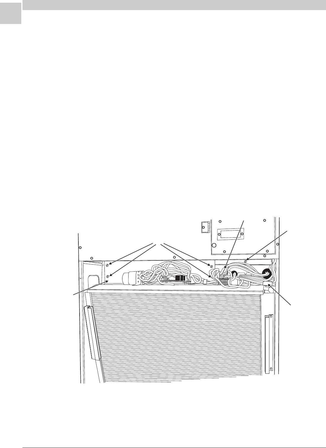
3-4
UNIT TEAR DOWN Magic-Pak: HW/HWC
SRM-HW/HWC 8/99
FILLER PANEL
HOLD DOWN
SCREWS
L1/L2 WIRES
6-PIN
LOW VOLTAGE
MOLEX PLUG
RIGHT SIDE
CHASSIS SCREW
Figure 3-2
Cooling Section
Chassis Removal:
The cooling chassis may be removed from behind the filter access door.
Refer to the following directions and Figures 3-1 to 3-4.
To remove the cooling chassis:
1. Disconnect all power to the unit.
2. Shut off and disconnect the gas supply.
3. Remove the filter access door (Figure 3-1).
4. Disconnect L1 and L2 from the compressor contactor (Figure 3-2).
5. Disconnect the 6-pin low voltage molex plug (Figure 3-2).
6. Remove the filler panel by removing the four hold down screws
(Figure 3-2).
7. Remove the right side chassis screw (Figure 3-2).
8. Remove the permagum seal on the base rails of the chassis (Figure
3-4).
9. Disconnect the drain tube from the evaporator drain pan (Figure 3-3).
10. Remove the chassis from the front of the unit, pulling it toward
yourself (Figure 3-4).
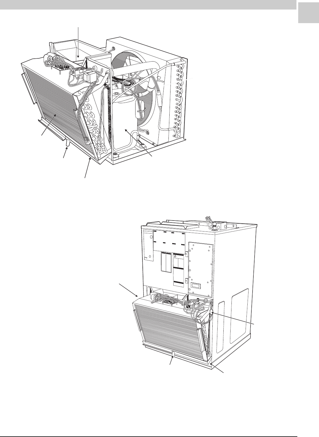
Service Reference Manual UNIT TEAR DOWN
3-5
SRM-HW/HWC 8/99
EVAPORATOR BLOWER MOTOR
COMPRESSOR
EVAPORATOR DRAIN PAN
EVAPORATOR
EVAPORATOR DRAIN
TUBE CONNECTION
Figure 3-3
LOW VOLTAGE
MOLEX PLUG
PERMAGUM SEAL
EVAPORATOR DRAIN
TUBE CONNECTION
DRAIN HOSE (NOT PICTURED)
ARMSTRONG P/N 03613A001
17" LONG
.63" (5/8") I.D.
.13" WALL THICKNESS
CHASSIS SHOWN
PARTIALLY REMOVED
Figure 3-4
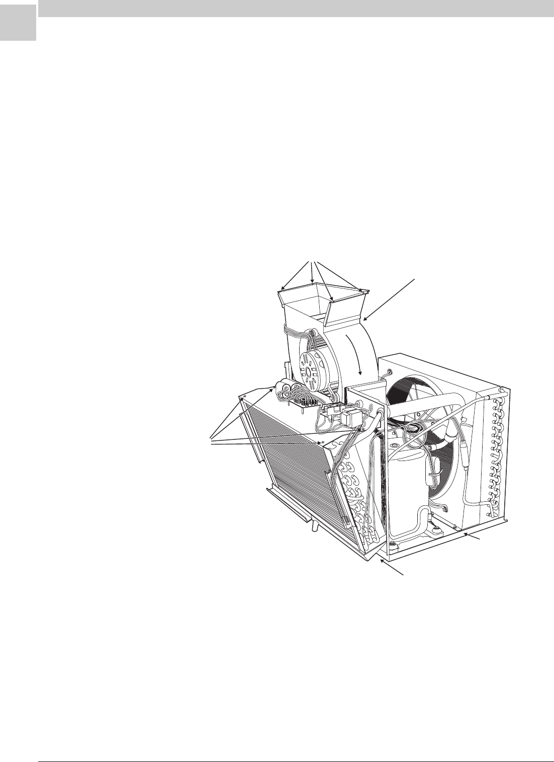
3-6
UNIT TEAR DOWN Magic-Pak: HW/HWC
SRM-HW/HWC 8/99
R
OT
A
T
I
O
N
MOUNTING SCREWS
EVAPORATOR BLOWER
ASSEMBLY
CONTROL PANEL
SCREWS
CHASSIS BASE
PERMAGUM SEAL
(BETWEEN BASE RAIL AND CHASSIS BASE)
Figure 3-5
Evaporator Blower Assembly Removal:
The evaporator blower assembly is removable as one complete section.
To remove the assembly, the chassis must be removed first (see page 3-
4). Refer to the following directions and Figure 3-5.
To remove the evaporator blower assembly:
1. Remove the four mounting screws from the blower assembly.
2. Remove the four control panel screws.
3. Slide control panel toward yourself about 1".
4. Disconnect the electrical wiring to the motor.
5. Pull blower assembly up and out from chassis.

4-1
Service Reference Manual COMPONENT LOCATION ILLUSTRATIONS
SRM-HW/HWC 2/99
Section 4 - Component Location
Illustrations
HW/HWC(3) Unit ................................. 4-2
HW/HWC(2) Unit ................................. 4-3
HW/HWC - Panels................................ 4-4
HW/HWC - Exterior Louver/Grill Panel .. 4-5
HWC Chassis Assembly ........................ 4-6
HWC Chassis Assembly - Top View ......... 4-7
HWC Chassis Assembly -
Circulating Air Blower Partially Removed 4-8
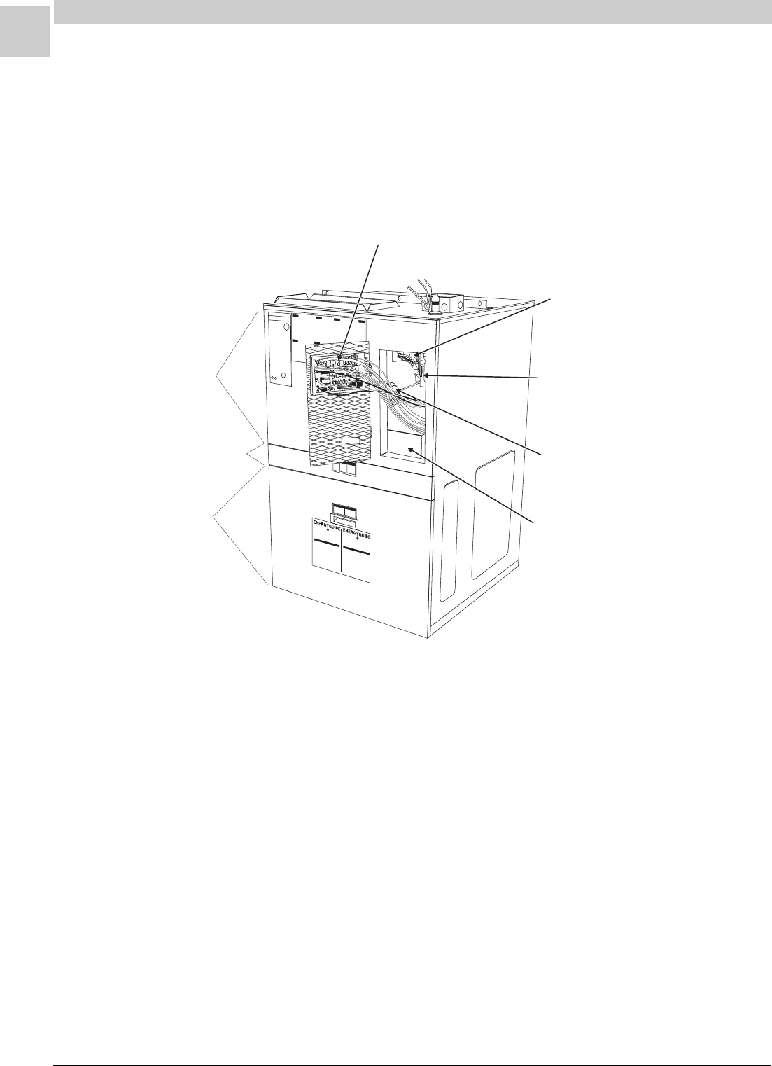
4-2
COMPONENT LOCATION ILLUSTRATIONS Magic-Pak: HW/HWC
SRM-HW/HWC 2/99
HW/HWC123,183,243,303
FIGURE 4-1
IGNITION/BLOWER CONTROL BOARD (*24)
UNITED TECHNOLOGIES 1097-83-400A/1097-400-I
ARMSTRONG P/N 44990-001
(DSI)*
MAIN LIMIT SWITCH (*52)
ARMSTRONG P/N 40154B007
GAS VALVE
HONEYWELL VR8105M8202
ARMSTRONG P/N 44987-001
PRESSURE SWITCH (*57)
BURNER TRAY
HEATING SECTION
CONTROL SECTION
COOLING SECTION
* SEE COMPONENT SECTION FOR FURTHER
DETAIL OF IGNITION/BLOWER CONTROL
The numbers in parentheses in the drawing above refer to the section number each part is assigned. These num-
bers are provided here to aid in locating the parts in the Parts List section found beginning on page 8-1.
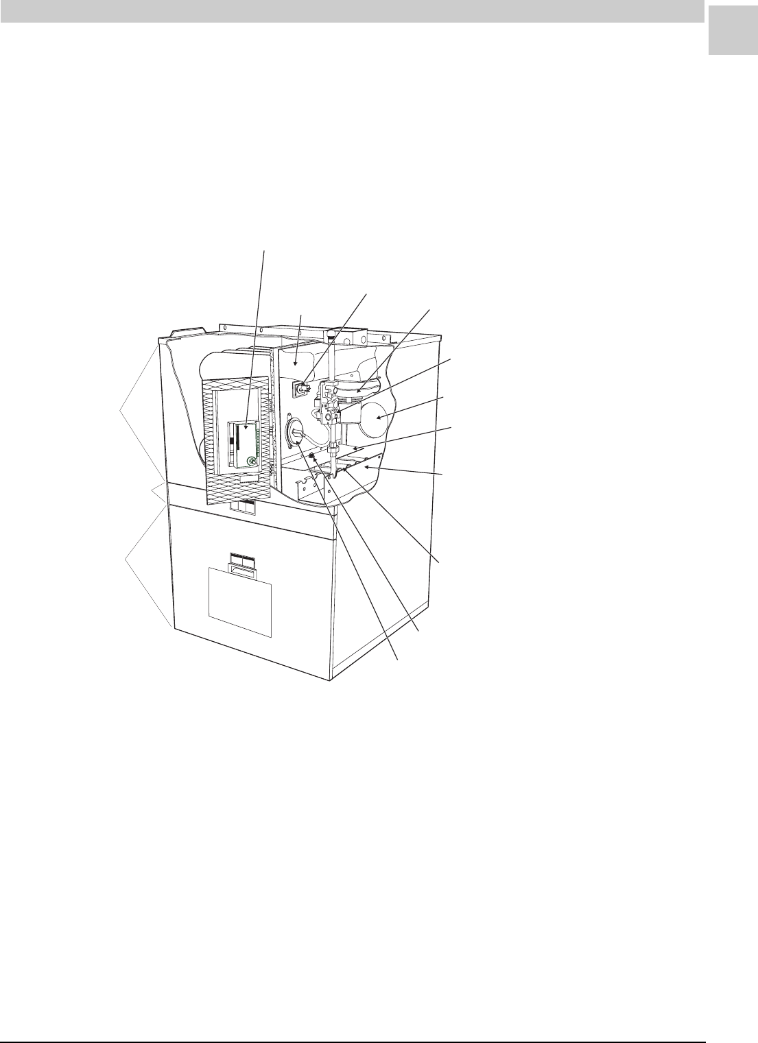
4-3
Service Reference Manual COMPONENT LOCATION ILLUSTRATIONS
SRM-HW/HWC 2/99
HW/HWC122, 182, 242, 302
FENWAL IGNITION CONTROL - 2 MODELS (*24)
FENWAL TRITON 2461D 900-227 - ARMSTRONG P/N 43110-002
FENWAL 05-29 - ARMSTRONG P/N 39048B001
(SEE NOTE BELOW)
FLUE BOX
MAIN LIMIT
SWITCH (*52) INDUCED DRAFT BLOWER/
COMBUSTION BLOWER (*63)
ARMSTRONG P/N 41144-001
GAS VALVE (*7)
WHITE RODGERS 25K49-120
ARMSTRONG P/N 43108-001
COMBUSTION AIR INLET (5")
BURNER COVER
BURNER TRAY ASSEMBLY
BECKETT BURNER MODELS:
TL109A-26K
TL109B-38K
TL109C-51K
TL109D-64K
FLAME ROLLOUT SWITCH (*55)
PRESSURE SWITCH (*57)
INDIVIDUAL BURNERS (*34)
BECKETT - ARMSTRONG P/N 41948-001
ARMSTRONG - ARMSTRONG P/N 39006B001
HEATING SECTION
CONTROL SECTION
COOLING SECTION
SEE COMPONENT SECTION FOR FURTHER
DETAIL OF IGNITION/BLOWER CONTROL MODELS
NOTE:
FIGURE 4-2
The numbers in parentheses in the drawing above refer to the section number each part is assigned. These num-
bers are provided here to aid in locating the parts in the Parts List section found beginning on page 8-1.
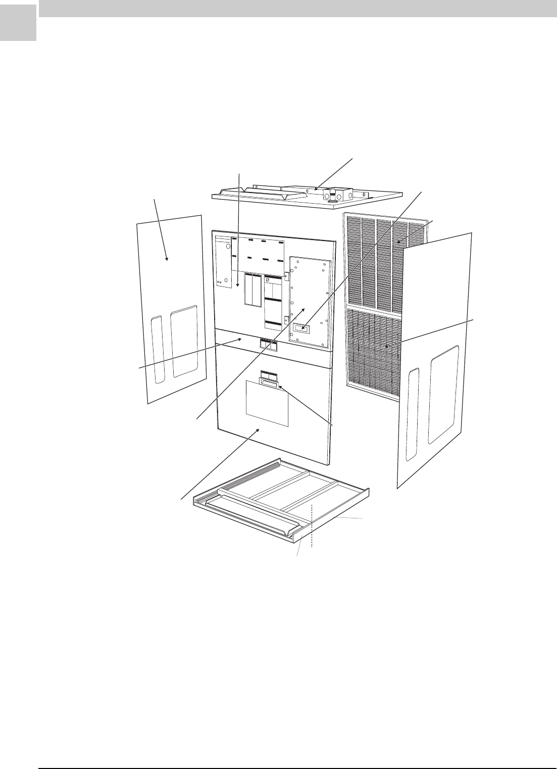
4-4
COMPONENT LOCATION ILLUSTRATIONS Magic-Pak: HW/HWC
SRM-HW/HWC 2/99
SIDE PANEL
ARMSTRONG P/N 38769D001
HEAT EXCHANGER ACCESS PANEL
ARMSTRONG P/N 38782D001
TOP PANEL ASSEMBLY
ARMSTRONG P/N 03455D007
INSPECTION WINDOW
ARMSTRONG P/N 38092A002
UPPER LOUVER PANEL
ARMSTRONG P/N 03545C000
LOWER GRILL
PANEL
ARMSTRONG
P/N 03551D100
DOOR HANDLE
ARMSTRONG
P/N 37701B001
SIDE PANEL
ARMSTRONG P/N 38769D002
HEATING COMPARTMENT DOOR
ARMSTRONG P/N 38987B004
COOLING CONTROL
ACCESS PANEL
ARMSTRONG P/N 03938C004
FILTER ACCESS DOOR
ARMSTRONG P/N 38785D001
(FILTER - 16.5" x 25" x .50"
ARMSTRONG P/N 06131B046)
UNIT BASE SECTION*
ARMSTRONG P/N 38771D101
UNIT BASE SECTION*
ARMSTRONG P/N 34805B003
* THE BASE PAN ASSEMBLY CONSISTS OF 2 SECTIONS
HW/HWC - Panels
Note: Panels and other associated parts found in the drawing above are not listed in the Parts List section that
begins on page 8-1.
FIGURE 4-3
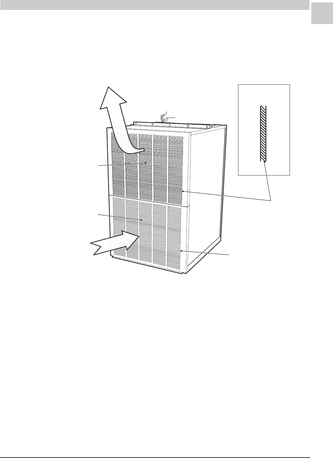
4-5
Service Reference Manual COMPONENT LOCATION ILLUSTRATIONS
SRM-HW/HWC 2/99
HW/HWC Exterior Louver/Grill Panel
CONDENSER
AIR FLOW
OUTLET
EXTERIOR UPPER LOUVER PANEL
ARMSTRONG P/N 03545C000
EXTERIOR LOWER GRILL PANEL
ARMSTRONG P/N 03551D100
CONDENSER
AIR FLOW
INLET
SIDE VIEW
LOUVERS POINT UPWARD
AT 45° ANGLE
GRILL IS FLAT WITH
RECTANGULAR OPENINGS
FIGURE 4-4
Note: Panels found in the drawing above are not listed in the Parts List section that begins on page 8-1.
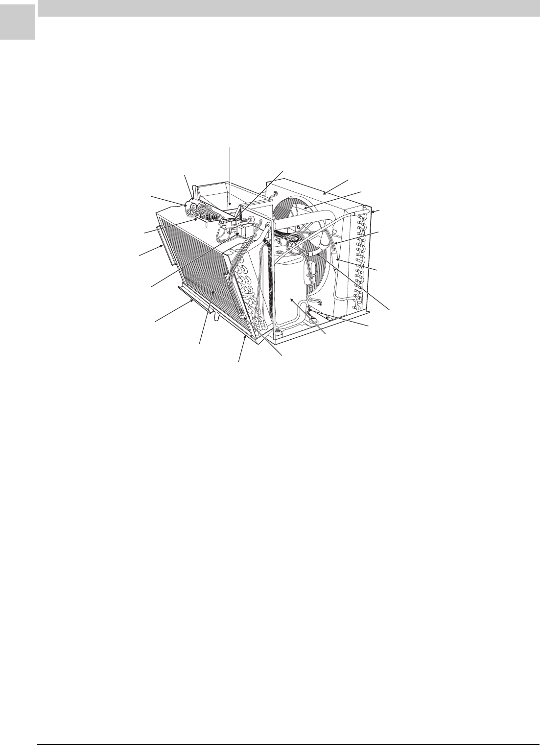
4-6
COMPONENT LOCATION ILLUSTRATIONS Magic-Pak: HW/HWC
SRM-HW/HWC 2/99
HWC Chassis Assembly
EVAPORATOR BLOWER MOTOR (*69)
COMPRESSOR CONTACTOR (*278)
ARMSTRONG P/N 03575C001
CONDENSING FAN SHROUD
CONDENSER FAN (*267, 268)
CONDENSING COIL (*250)
CAPILLARY TUBE
METERING DEVICE (*256)
FILTER DRIER/DISTRIBUTOR (*301)
(12) ARMSTRONG P/N 39059B001
(18-24) ARMSTRONG P/N 39059B002
(30) ARMSTRONG P/N 39059B003
SUCTION LINE/PORT
DISCHARGE LINE/PORT
COMPRESSOR (*262)
FILTER RETAINER
ARMSTRONG P/N 38072B001
EVAPORATOR DRAIN PAN
ARMSTRONG P/N 38918B001
EVAPORATOR (*255)
FILTER STOP
ARMSTRONG P/N 38073BOO1
FILTER SIZE 16.5" X 25.5" X .5"
LOW VOLTAGE
CONTROL TRANSFORMER (*1)
ARMSTRONG P/N 39370B001
BLOWER CONTROL BOARD (*5)
ARMSTRONG P/N 39029B002
FILTER RETAINER
ARMSTRONG P/N 38072B001
CONDENSING FAN
CAPACITOR (*271)
COMPRESSOR CAPACITOR (*271)
FIGURE 4-5
The numbers in parentheses in the drawing above refer to the section number each part is assigned. These num-
bers are provided here to aid in locating the parts in the Parts List section found beginning on page 8-1.
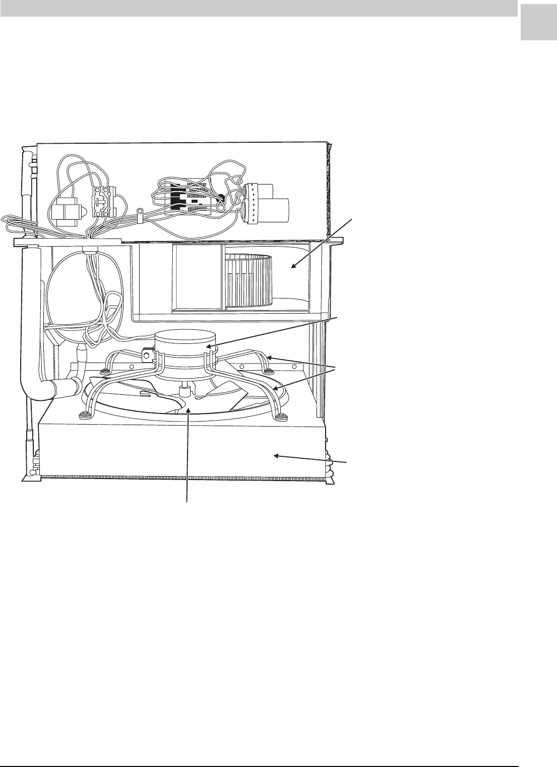
4-7
Service Reference Manual COMPONENT LOCATION ILLUSTRATIONS
SRM-HW/HWC 2/99
SEE FIGURE 4-7 FOR
CIRCULATING AIR BLOWER
COMPONENTS
CONDENSER MOTOR (*267)
(12-18) ARMSTRONG P/N 41282-001
(24-30) ARMSTRONG P/N 41254-001
CONDENSER FAN MOTOR BRACKET (*269)
ARMSTRONG P/N 03982D004
FAN SHROUD
FAN BLADE (*268)
(12-18) ARMSTRONG P/N 39085B001 (3 BLADE/24° PITCH/18”)
(24-30) ARMSTRONG P/N 39062B001 (5 BLADE/26° PITCH/18”)
FIGURE 3-7 TOP VIEW — HWC CHASSIS ASSEMBLY
FIGURE 4-6
HWC Chassis Assembly - Top View
The numbers in parentheses in the drawing above refer to the section number each part is assigned. These num-
bers are provided here to aid in locating the parts in the Parts List section found beginning on page 8-1.
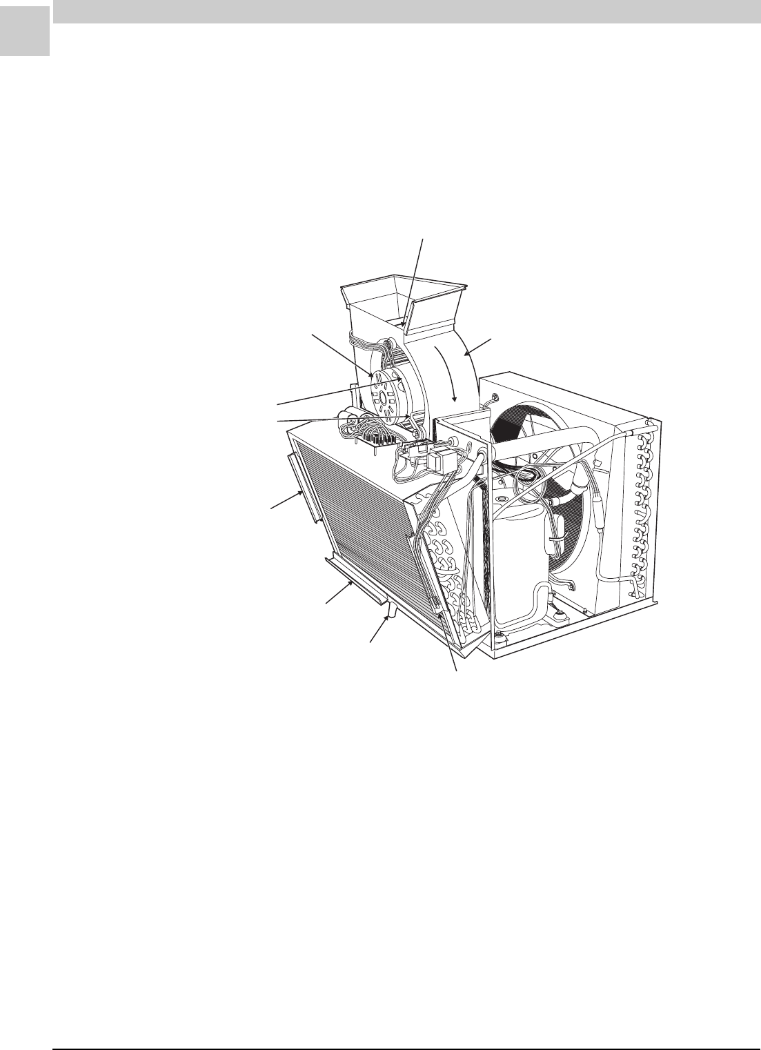
4-8
COMPONENT LOCATION ILLUSTRATIONS Magic-Pak: HW/HWC
SRM-HW/HWC 2/99
BLOWER WHEEL (*73)
ARMSTRONG P/N 34833B001
10.75" x 4"
CIRCULATING AIR BLOWER MOTOR (*69)
(12) ARMSTRONG P/N 39045B001
(24-30) 39046B001
MOTOR MOUNTING BRACKET (*71, 72)
BAND - ARMSTRONG P/N 07407B000 (1)
ARMS - ARMSTRONG P/N 07408B004 (3)
BLOWER HOUSING (*74)
ARMSTRONG P/N 39010B001
SEE FIGURE 4-6
FOR FAN CONDENSING
PARTS
FILTER RETAINER
ARMSTRONG P/N 38072B001
FILTER STOP
ARMSTRONG P/N 38703B001
FILTER RETAINER
ARMSTRONG P/N 38072B001
EVAPORATOR DRAIN
TUBE CONNECTION
.63" (5/8")*
FILTER (*127) SIZE
16.5" x 25" x .50"
ARMSTRONG P/N 06131B046
NOTE:
WHEN USING A REPLACEMENT FILTER WITH
A MANUFACTURED FRAME, THE DIMENSIONS
MAY NEED TO BE REDUCED FOR PROPER FIT.
TAKE AND RECORD MEASUREMENTS FOR
PROPER FIT.
R
OT
A
T
I
O
N
REQUIRES DRAIN HOSE
ARMSTRONG P/N 03613A001 (NOT SHOWN)
(5/8") I.D.
*
HWC Chassis Assembly -
Circulating Air Blower Partially Removed
FIGURE 4-7
The numbers in parentheses in the drawing above refer to the section number each part is assigned. These num-
bers are provided here to aid in locating the parts in the Parts List section found beginning on page 8-1.

Service Reference Manual UNIT COMPONENTS
5-1
SRM-HW/HWC 2/99
Section 5 - Unit Components
Transformer ........................................ 5-3
Gas Valves........................................... 5-4
White-Rodgers 25K49 ................................ 5-4
Honeywell 8105 ......................................... 5-5
Blower Control Boards ......................... 5-6
United Technologies Model 1010-611 .......... 5-6
Heatcraft Model IBC-H4C401 ..................... 5-7
Ignition Controls .................................. 5-8
Fenwal Triton 2461D.................................. 5-8
Fenwal 05-29 DSI .................................... 5-10
Integrated Blower/Ignition Controls .... 5-11
Induced Draft Blower.......................... 5-14
Burners............................................. 5-15
Manifold Orifices ................................ 5-17
Contactor .......................................... 5-18
Main (High) Limit Switch ..................... 5-19
Flame Rollout Switch .......................... 5-20
Pressure Switch ................................ 5-21
Pressure Switch Problems ........................ 5-23
Checking Pressure Switch Operation.......... 5-24
Compressors ..................................... 5-28
Tecumseh ................................................ 5-30
Copeland ................................................. 5-32
Drier-Filters....................................... 5-34

5-2
UNIT COMPONENTS Magic-Pak: HW/HWC
SRM-HW/HWC 2/99
HWC Capillary Tubes .......................... 5-35
Capacitors ......................................... 5-39
Evaporator Blower Motor ................... 5-40
Condenser Fan Motor ......................... 5-40
Capacitors-Run .................................. 5-41
Fan Blades......................................... 5-42
Exterior Grill Panels ........................... 5-44
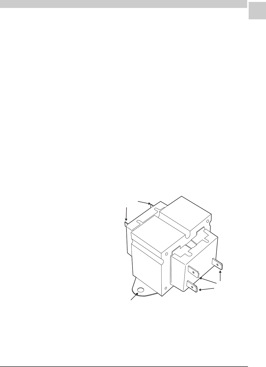
Service Reference Manual UNIT COMPONENTS
5-3
SRM-HW/HWC 2/99
Unit Components
This section provides a brief description of the most important compo-
nents within the Magic-Pak HW/HWC units. The information presented
here is not intended to take the place of the instructions and printed
literature packed with each component by the original manufacturer. The
section number for each component is listed in parentheses following the
component name. This number refers to the section number assigned to
each part in the Parts List section beginning on page 8-1.
Transformer (*1)
The transformer supplies 24 VAC from its secondary winding to operate
the blower control board, gas valve and ignition control depending on the
particular model. Transformers are typically rated at 40 VA, 50/60 Hz.
Note: Secondary leads may exit from top of transformer.
240V
COM
208V
208/240 VAC
Primary
24 VAC
Secondary
.25 x .032
Quick Connect
Terminals
""
.19 x .020
Quick Connect
Terminals
""
.188 Diameter Holes"
FIGURE 5-1 24-volt Transformer (Typical Configuration)
Transformer Specifications
Manufacturer: Basler Electric
Model: 31264-GEK
Armstrong P/N 39370B001
Primary: 208/240V
Secondary: 24V
Rating: 40VA
Dimensions: 2.28" W x 1.94" H x 3.12" D
Base - 3.25" W (2.81" between I.D. of holes)
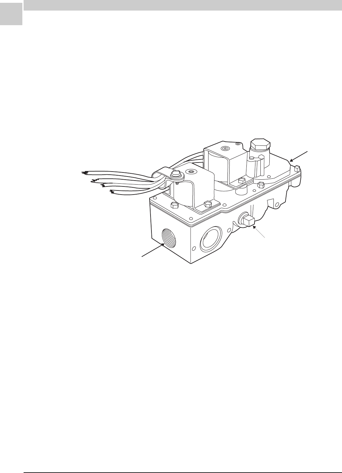
5-4
UNIT COMPONENTS Magic-Pak: HW/HWC
SRM-HW/HWC 2/99
Gas Valves (*7)
Gas Valve Specifications
Manufacturer: White-Rodgers
Model: 25K49-120
Armstrong P/N 43108-001
Dimensions: 1.97" W x 5.31" L
Nominal Operating Currents: 25VAC/60Hz/.5A
Regulator set at 3.50 +/– .02” W.C. at 55.6 cubic Ft./Hr of air at
standard conditions (with valve in vertical position, inlet up).
3/8 - 18 N.P.T."
Inlet
Pipe Plug
1/8 - 27 N.P.T."
3/8 - 18 N.P.T.
Out
"
let
FIGURE 5-2 White-Rodgers Gas Valve
White-Rodgers 25K49-120
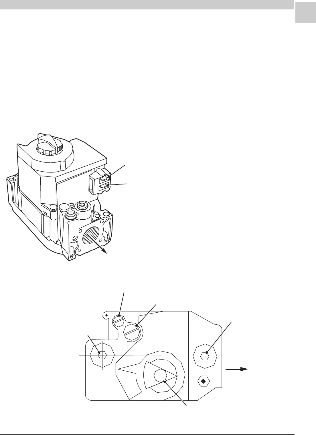
Service Reference Manual UNIT COMPONENTS
5-5
SRM-HW/HWC 2/99
Honeywell 8105 Series
Gas Valve Specifications
Manufacturer: Honeywell
Model: VR8105M8202
Armstrong P/N 44987-001
Dimensions: 2.70" W x 4.75" L
Nominal Operating Currents: 25VAC/60Hz/.5A
Regulator Setting: 3.50 +/– .3" W.C.
Pipe Size: .50" Inlet x .375" Outlet
Valve Amp Draw: .5 A
1" Drop Capacity: 85,000 Btuh
Max. Regulator Capacity: 120,000 Btuh
Temperature Rating: – 40°F to +175°F
FIGURE 5-3 Honeywell Gas Valve
Main Valve Terminal (Hot)
Main Valve Common Terminal
FLOW
OFF
ON
1/8 NPT Inlet Pressure Tap"
Reference Tube Vent
Manifold Pressure Adjustment
FLOW
On/Off Switch
1/8 NPT Outlet Pressure Tap"
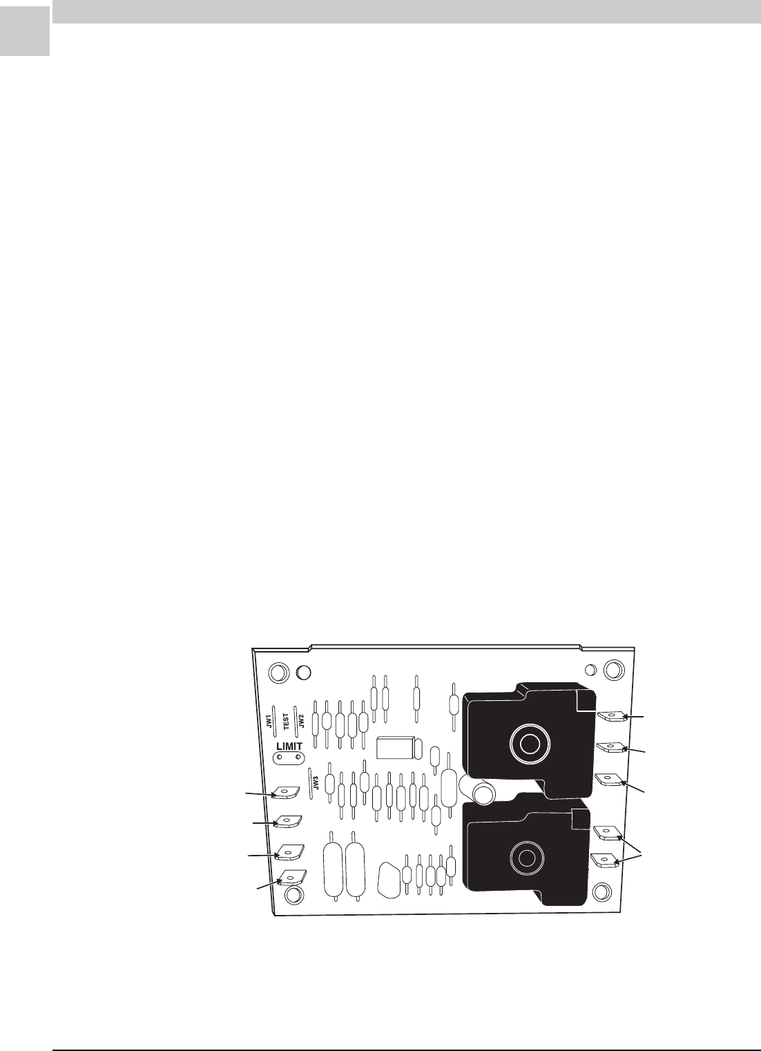
5-6
UNIT COMPONENTS Magic-Pak: HW/HWC
SRM-HW/HWC 2/99
Blower Control Boards (*5)
A separate blower control board is used in the Magic-Pak HW/HWC
models that do not use integrated ignition/blower control boards. Blower
control boards from two different manufacturers are used in these HW
and HWC units. The two blower control boards are explained in detail in
the following pages.
United Technologies Model 1010-611
9840A
R
W
G
C
L1
M1
M2
HEAT
COOL
39029B002
1010-83-611A
24VAC Power
24VAC Heat Call
24VAC Common
L1 Line Voltage
Cool Speed
L1 Power Out
Heat Speed
L1 Power Out
Dumb Terminals
(Park)
24VAC
Fan Call (Fan On)
Cooling Call (Fan Auto)
Blower Control Board Specifications
Manufacturer: United Technologies
Model: 1010-611
Armstrong P/N 39029B002
Operating Voltage: 18-30VAC 60 Hz
60 Hz Power Requirement: 4 VA max.
Operating Temperature: – 40°F to +170°F
Wiring Connections: All Male .250" x .032" Quick Connect Tabs
Performance Specifications (all timings +/– 1 second):
Heating: On Delay Timing - 60 seconds
Off Delay Timing - 90 seconds
Cooling: On Delay Timing - 15 seconds
Off Delay Timing - 90 seconds
Heating and Cooling Output Rating:
12 F.L.A., 30 L.R.A. at 120VAC for 100,000 Cycles
10 F.L.A., 30 L.R.A. at 240VAC for 100,000 Cycles
Both heat and cool outputs cannot be energized simultaneously.
FIGURE 5-4 United Technologies Blower Control Board 1010-611
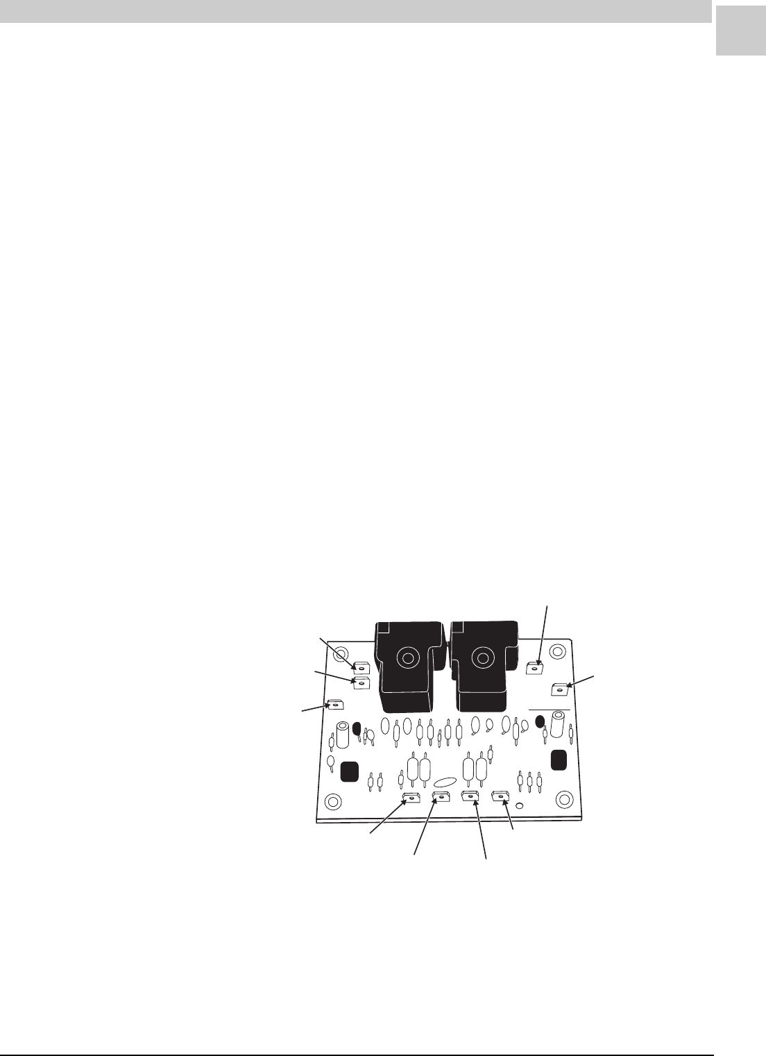
Service Reference Manual UNIT COMPONENTS
5-7
SRM-HW/HWC 2/99
Heatcraft Model IBC-H4C401
Blower Control Board Specifications
Manufacturer: United Technologies
Model: 1010-611
Armstrong P/N 39029B002
Operating Voltage: 18-30VAC 60 Hz
60 Hz Power Requirement: 4 VA max.
Operating Temperature: – 40°F to +170°F
Wiring Connections: All Male .250" x .032" Quick Connect Tabs
Performance Specifications (all timings +/– 1 second):
Heating: On Delay Timing - 60 seconds
Off Delay Timing - 90 seconds
Cooling: On Delay Timing - 15 seconds
Off Delay Timing - 90 seconds
Heating and Cooling Output Rating:
12 F.L.A., 30 L.R.A. at 120VAC for 100,000 Cycles
10 F.L.A., 30 L.R.A. at 240VAC for 100,000 Cycles
Both heat and cool outputs cannot be energized simultaneously.
HEATCRAFT
M2
COOL
HEAT
WCRG
L1
M1
39029B002
L1 Line Voltage
Heat Speed
L1 Power Out
Cool Speed
L1 Power Out
Dumb Terminal
(Park)
Dumb Terminal
(Park)
24 VAC Heat Call
24 VAC Common 24 VAC Power
24 VAC (Fan On/Cooling Fan Auto)
FIGURE 5-5 Heatcraft Blower Control Board IBC-H4C401
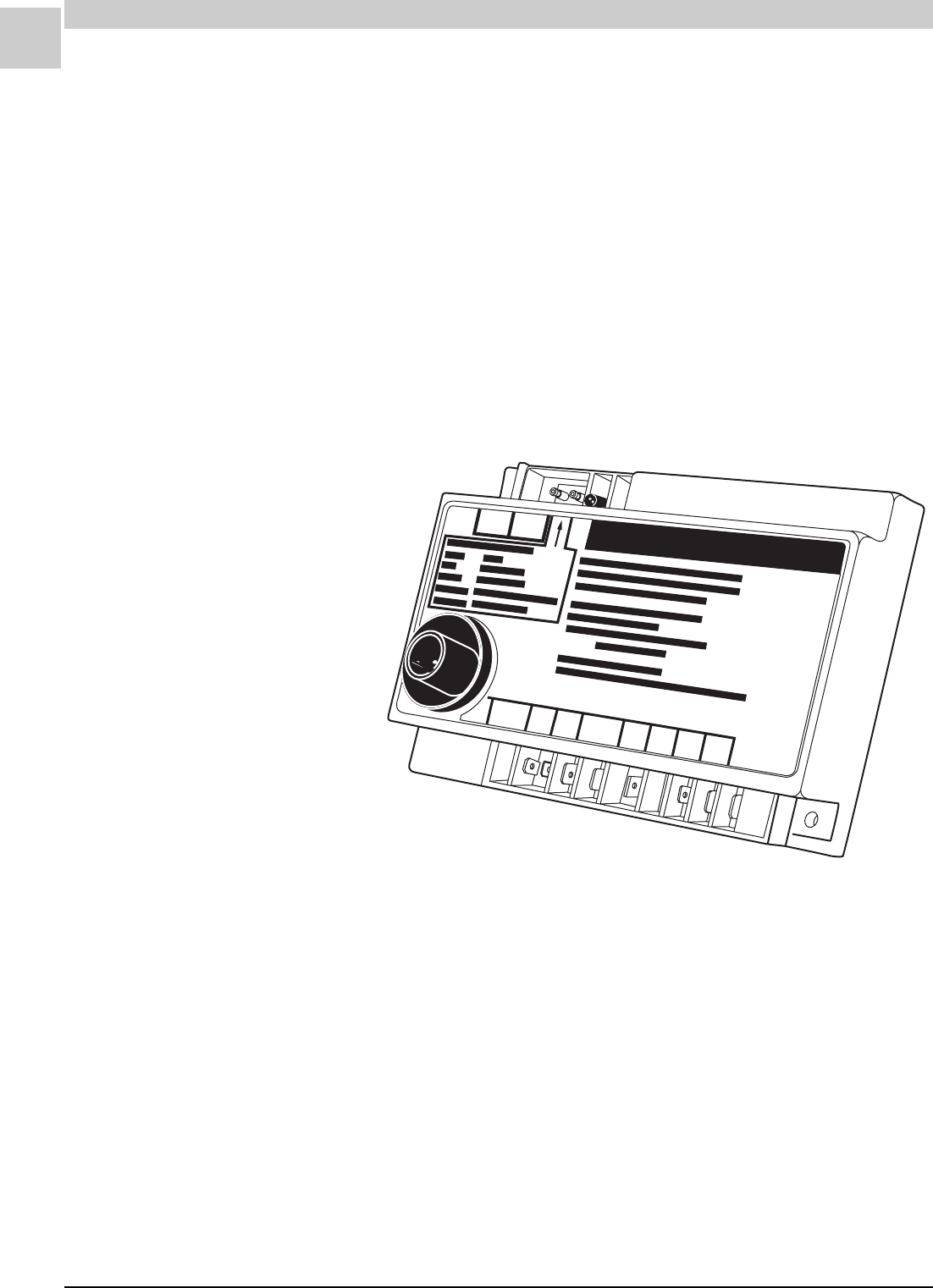
5-8
UNIT COMPONENTS Magic-Pak: HW/HWC
SRM-HW/HWC 2/99
Ignition Controls (*24)
FENWAL
®
¨
V2
GND
FC-
CAUTION: HIGH VOLTAGE DISCONNECT WIRING BEFORE SERVICING
FC+
24
VAC
L1
IND V1 PSW TH
Fenwal Triton 2461D
Ignition Control Specifications
Manufacturer: Fenwal
Model: Triton 2461D
Armstrong P/N 43110-002
Pre-purge: 30 seconds
Ignition: 15 seconds
Input: 24VAC, 50/60 Hz 300 mA
Valve: 24VAC, 2.0 A max.
Inducer: 120VAC, 3.0 A or 240VAC, 1.5 A, 1/4 HP
Ambient: – 40°F to +160°F
ANSI Z21.20-1993 CAN/CSA-C22.2 No. 199-M89
FIGURE 5-6 Fenwal Triton 2461D Ignition Control

Service Reference Manual UNIT COMPONENTS
5-9
SRM-HW/HWC 2/99
Diagnostics (Fenwal Triton 2461D)
1. Diagnostic LED flash rate is 1/4 second “ON”, 1/4 second “OFF”
followed by up to four seconds “OFF” before repeating the code.
2. Only one code is displayed at a time.
3. During a “STEADY ON” code, the LED may blink off momentarily.
4. Diagnostic codes may be reset by removing the power from the
control for three seconds, then reapplying power. (Cycle thermostat
“OFF” for three seconds, then back “ON”.)
The following ignition control board LED codes indicate normal or
abnormal operations:
TABLE 5-1 Triton 2461D Diagnostic Flash Code
NOYDAETS
otderewopsilortnocehtemithcaeputratstasdnocesruofotpurofdesusiedocsihT eht,detcetedsimelborpafI.kcehccitsongaidflesagnimrofrepsilortnocehttahtetacidni nosiDELfI.sdnocesytnewtslauqehcihwsemiteviffolatotaroftaeperlliwsisongaidfles .eruliaflortnocasetacidnisiht,sdnoces02rofydaets
HSALFENO
sihT.)WSP(tupnihctiwserusserpahtiwsledomnoylnodesU.tluafwolfrianasetacidnI .yaledemitdenimretederparetfaetatsreporpmiehtnisitupniWSPehtfiylnoevitcasiedoc ,)stcatnocdesolc(snigebtaehrofllacehtnehwderewopsawtupniWSPehtfI:elpmaxeroF lliwhsalfDELehtesiwrehtoffoogottupniWSPehtrofemitdexifawollalliwlortnoceht ehtretfaemityaleddexifanihtiwderewoptonsitupniWSPehfi,ylesrevnoC.ecnemmoc devomersitupniWSPehtfI.ecnemmoclliwhsalfDELeht,dezigrenesirotomrecudni WSPehtfI.yletaidemmievlavsagehtmorfdevomereblliwrewop,elcycgnitaehagnirud .ecnemmoclliwhsalfDELeht,emitdexifanihtiwdeilppaertonsitupnirewop
OWT
SEHSALF
saeciwthsalflliwDEL.taehrofllaconhtiwroecneuqesfotuodetcetedemalfasetacidnI .tneserpsiemalfehtsagnolsaeunitnocdnaecneuqesfotuodetcetedsiemalfsanoos siemalfnehwtiucricrecudniehtrewoposlalliwtiucriclortnocrecudninahtiwslortnoC .ecneuqesfotuodetceted
EERHT
SEHSALF
eunitnoclliwedocsihT.detelpmocneebevahseirtnoitingillaretfatuokcolnoitingisetacidnI eht,tesercitamotuaruohenohtiwdeppiuqesledomnO.sniamertaehrofllacehtsagnolsa .snigebtpmettanoitingiwenanehwpotslliwedoc
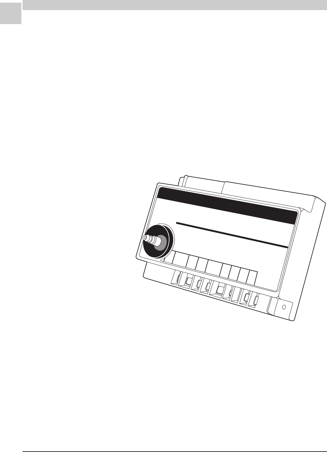
5-10
UNIT COMPONENTS Magic-Pak: HW/HWC
SRM-HW/HWC 2/99
Fenwal 05-29 DSI
G
N
D
V2 T2 S1 V1
P.
SW
L1 IND
FENWAL
®
Series 05-29 DSI
CAUTION
HIGH VOL TAGE
AUTOMATIC IGNITION SYSTEM
FIGURE 5-7 Fenwal 05-29 Ignition Control
Ignition Control Specifications
Manufacturer: Fenwal
Model: 05-29 DSI
Armstrong P/N 39048B001
Relative Humidity Rating: 5 to 90% RH at 95°F
Flame Current: 3 mA min.
Spark Gap: 1/8"
Trial for Ignition: 6.8 seconds
Pre-purge: 30 seconds
Input: 24VAC from TS and P.SW to ground
Gas Valve Contacts: 24VAC, 600 mA max.
Blower Output: Relay between L1 and IND, 10 A at 250VAC
Ambient: – 40°F to +150°F
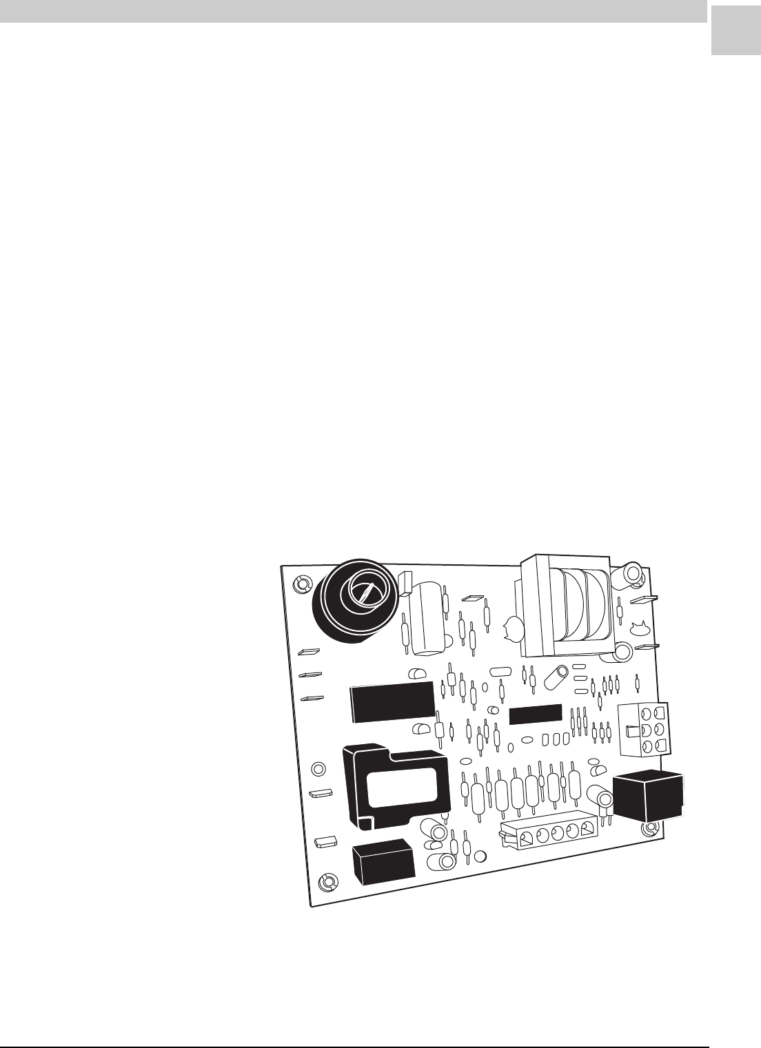
Service Reference Manual UNIT COMPONENTS
5-11
SRM-HW/HWC 2/99
Integrated Blower/Ignition Control (*24)
United Technologies Model 1097-400-1
The integrated control combines the actions and purposes of the indi-
vidual ignition and blower control boards found on other units. It automati-
cally monitors and controls the operation of the gas burners, gas valve,
induced draft blower and circulating blower.
The control has a built-in diagnostic function, quick gas valve shutoff and
automatic ignition retry when it detects that a fault condition has been
corrected. If a fault is detected, the controls goes into fault mode and
flashes the single LED indicator at a preset rate for that particular fault
condition. (See Diagnostic Flash Code found in Table 4-1 on page 4-8 or
Diagnostic Indicator code printed on unit label.)
UNUSED
ACB
HEAT
ACB
COOL
FLAME
24VAC
GROUND
CMB
BL WR
L1
YCWGR
FIGURE 5-8 United Technologies Model 1097 Integrated Control
Integrated Control Specifications
Manufacturer: United Technologies
Model: 1097-400-1
Armstrong P/N 44990-001
Operating Temperature: – 40°F to +175°F
Timing Tolerance: +/– 10%
Input Voltage: 18-30VAC, 50/60 Hz
Combustion Blower: 1/8 HP @ 120/240VAC
Circulating Blower: 1/2 HP @ 120VAC, 1 HP @ 240VAC
Gas Valve: 24VAC, 60 Hz, 1.0 A

5-12
UNIT COMPONENTS Magic-Pak: HW/HWC
SRM-HW/HWC 2/99
TABLE 5-2 UTech Model 1097 Diagnostic Flash Code
United Technologies Model 1097-400-1 (cont.)
Quick Connect Terminal Descriptions
1 24VAC HOT - from Transformer
2 GROUND = 24VAC Return
4 CMB BLWR = Combustion Blower (Line Voltage)
5 L1 = Line Voltage
9 ACB COOL = Air Circulating Blower Cool Speed (Line Voltage)
10 ACB HEAT = Air Circulating Blower Heat Speed (Line Voltage)
11 UNUSED (Park)
12 FLAME = Flame Probe
Molex/Amp Plug-in Description
1 Roll-out Switch Return
2 Hi Limit Return/Pressure Switch Out
3 Gas Valve Common
4 Gas Valve Out
5 Pressure Switch Return
6 Roll-out Switch Out
Thermostat Input
R 24VAC to Thermostat (RED)
G Manual Fan Input from Thermostat (GREEN)
W Heat Demand Input from Thermostat (WHITE)
C Common Ground to Thermostat
Y Cool Demand Input from Thermostat (YELLOW)
Diagnostics (United Technologies 1097-400-1)
The following blower/ignition control board LED codes indicate normal or
abnormal operations:
HSALFWOLStaeHrofllaCoN,noitarepOlamroN
HSALFTSAFtaeHrofllaC,noitarepOlamroN
HSALF2emalFniatsuSrotceteDotdeliaF-tuokcoLmetsyS
HSALF3desolCronepOhctiwSerusserP
HSALF4nepOhctiwStuolloRrotimiLhgiH
HSALF5dezigrenEtoNevlaVsaGdnadesneSemalF
YDAETS)kcehc-fleS;eruliaFrellortnoc-orciM(eruliaFlanretnI

Service Reference Manual UNIT COMPONENTS
5-13
SRM-HW/HWC 2/99
United Technologies Model 1097-400-1 (cont.)
Heat Mode
Pre-purge 30 seconds
Inter-purge 30 seconds
Post-purge 5 seconds
Trial Time 10 seconds
# of Trials 3
Board to reset from lockout after 60 minutes.
Fan On Delay
Cool 5 seconds (fixed)
Heat 30 seconds (fixed)
Fan Off Delay
Cool 90 seconds (fixed)
Heat 120 seconds (fixed)
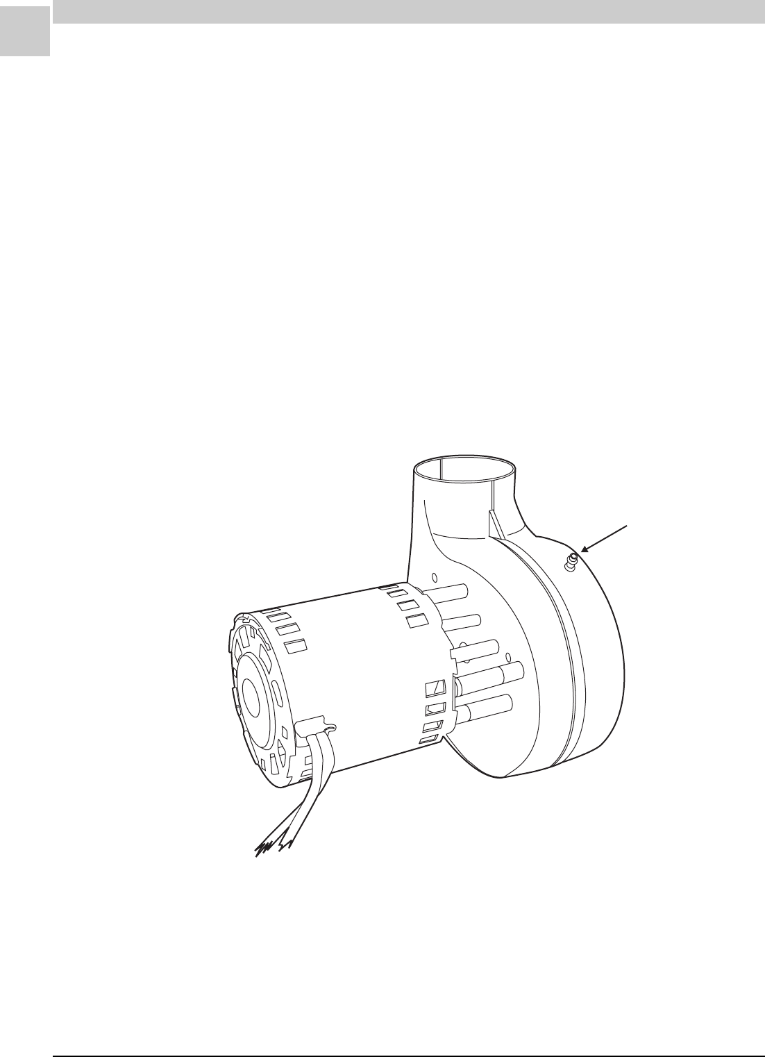
5-14
UNIT COMPONENTS Magic-Pak: HW/HWC
SRM-HW/HWC 2/99
Induced Draft Blower (*63)
The induced draft blower is also referred to as a “combustion” blower,
since its purpose is to establish flow of combustion air through the heat
exchanger. Mounted at the outlet of the secondary heat exchanger, the
blower establishes a negative pressure within the heat exchanger and
exhausts the flue products outside the structure.
Blower motors operate at a fixed speed.
.32 Extension Barbed Tube
for .096 (+/ .005 ) I.D.
Pressure Tap
"
"
"
FIGURE 5-9 Magnetek JBIMI37NS Induced Draft Blower
Induced Draft Blower Specifications
Manufacturer: Magnetek
Model: JBIMI37NS
Armstrong P/N 41144-001
208/240VAC, 60 Hz, Single Phase, .55 FLA, 3000 RPM, .031 HP
Rotation CW LE
Continuous Duty
Features: Ball Bearing; Stainless Steel Shaft;
Motor Grounded to Blower Housing
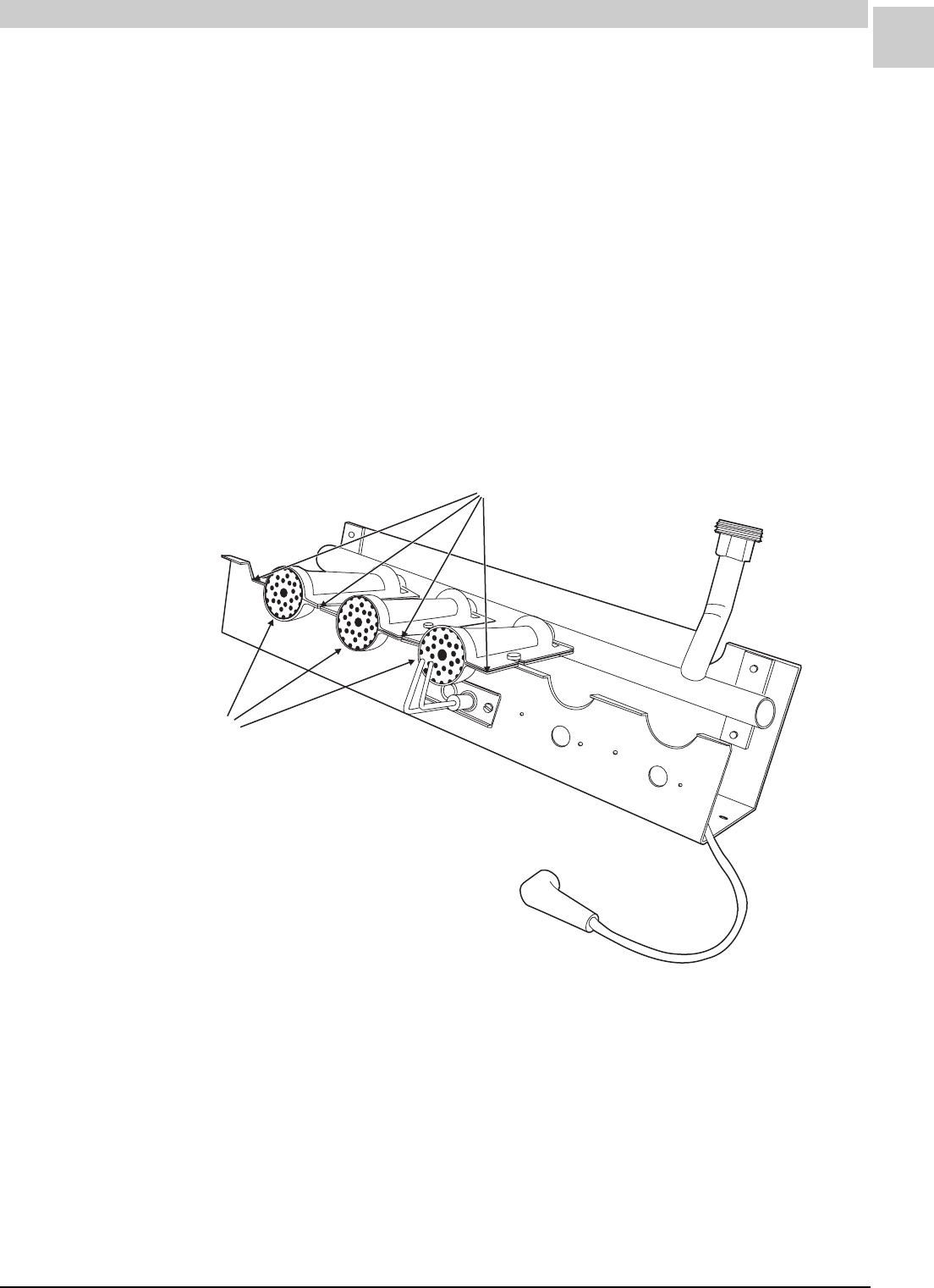
Service Reference Manual UNIT COMPONENTS
5-15
SRM-HW/HWC 2/99
Burners (*34)
The Magic-Pak HW and HWC units covered in this manual use a burner
design called the “inshot” type. No adjustment is provided for primary or
secondary air. For best operation, keep the burners clean. Use the
correct orifice size and adjust the manifold pressure for the fuel being
used and the operating altitude.
Burner Specifications
Manufacturer: Beckett Gas
Model: AR086
Armstrong P/N 41948-001
Burner Dimensions: 4.50" x 2.48"
FIGURE 5-10 Typical Burner Arrangement
Burners
Burner Carryover Gap
.025 (+/ .002 )""
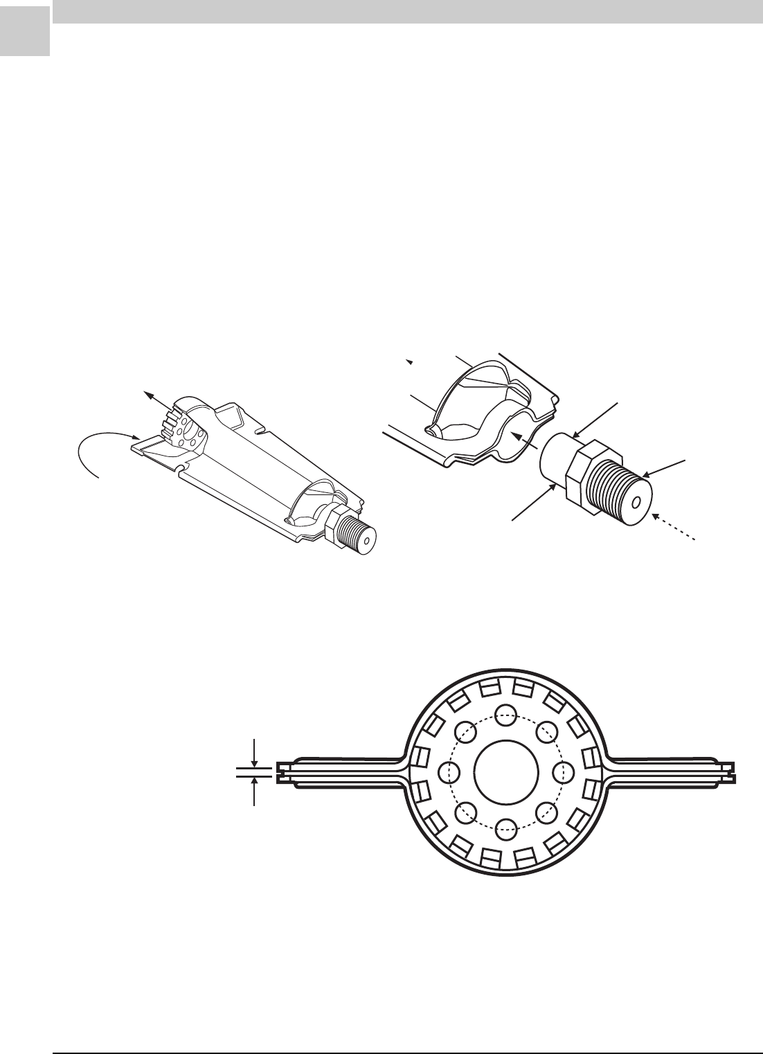
5-16
UNIT COMPONENTS Magic-Pak: HW/HWC
SRM-HW/HWC 2/99
Flame Carryover Problems
During ignition, the flame must travel uninterrupted from one burner to the
rest of the burners.
Causes:
• Carryover “wing” on burner is plugged with insects or debris
• Improper gap setting on wings
• Incorrect gas pressure
The burner wing has a specified gap (typically 0.025" +/– .002"), which
must carry gas and a small flame to allow flame carryover from one
burner to the next. Check the gap settings on all burners.
Orifice
Smooth end slips
into burner
Gas Entry
Threads
into manifold
Flame Exit
.025 gap (+/ .002 )
for flame carryover
""
FIGURE 5-11 Inshot Burners
FIGURE 5-12 Burner Wing Gap
Armstrong P/N: 41948-001
Gap = .025" +/– .002"
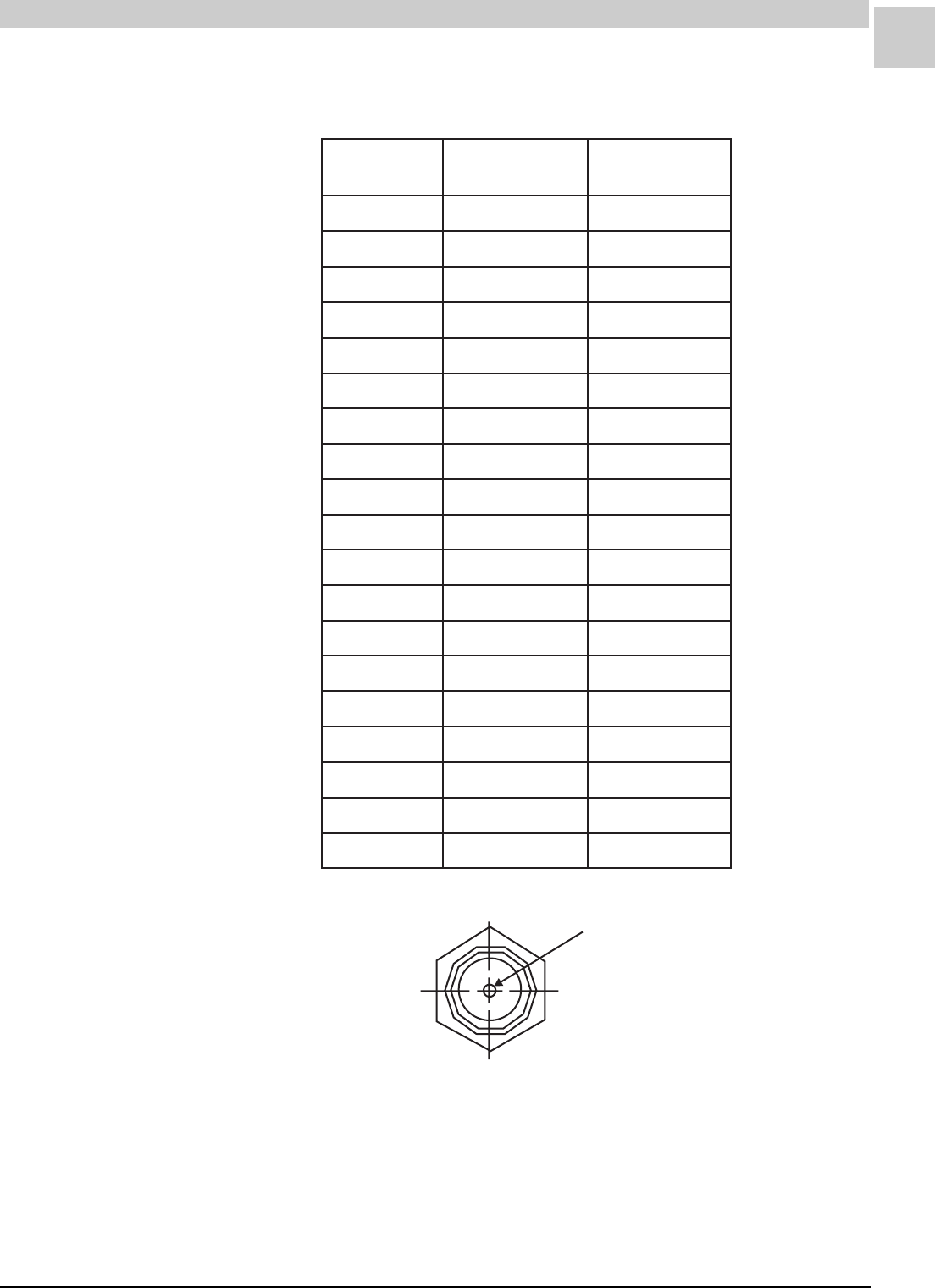
Service Reference Manual UNIT COMPONENTS
5-17
SRM-HW/HWC 2/99
Manifold Orifices (*13)
Hole Diameter
FIGURE 5-13 Manifold Orifice
TABLE 5-3 Manifold Orifice Specifications
gnortsmrA
N/P
retemaiDeloH
eziSllirD
retemaiDeloH
)sehcni(
100B03093knalBknalB
200B03093150760.
300B03093255360.
400B03093355950.
500B03093450550.
600B03093160930.
700B03093250830.
800B03093360730.
900B03093440680.
010B03093745870.
110B03093550250.
210B03093655640.
310B03093560530.
410B03093460630.
510B03093730401.
610B03093140690.
710B03093040890.
810B03093340980.
910B03093245390.
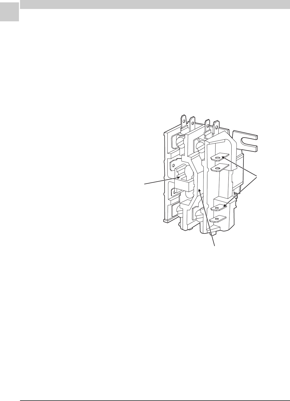
5-18
UNIT COMPONENTS Magic-Pak: HW/HWC
SRM-HW/HWC 2/99
Contactor (*278)
L1 L2
T1 T2
Open Contact
Closed Contact
Low Voltage
Coil Terminals
FIGURE 5-14 Honeywell Contactor Model R8242A-1008
Contactor Specifications
Manufacturer: Honeywell
Model: R8242A-1008
Armstrong P/N 7535C001
Single-phase, Single-pole, 25 F.L.A., 125 L.R.A
Coil: 24VAC, 50/60 Hz
Line Voltage: 240/277
Coil Resistance at 70°F: 8 - 10 ohms
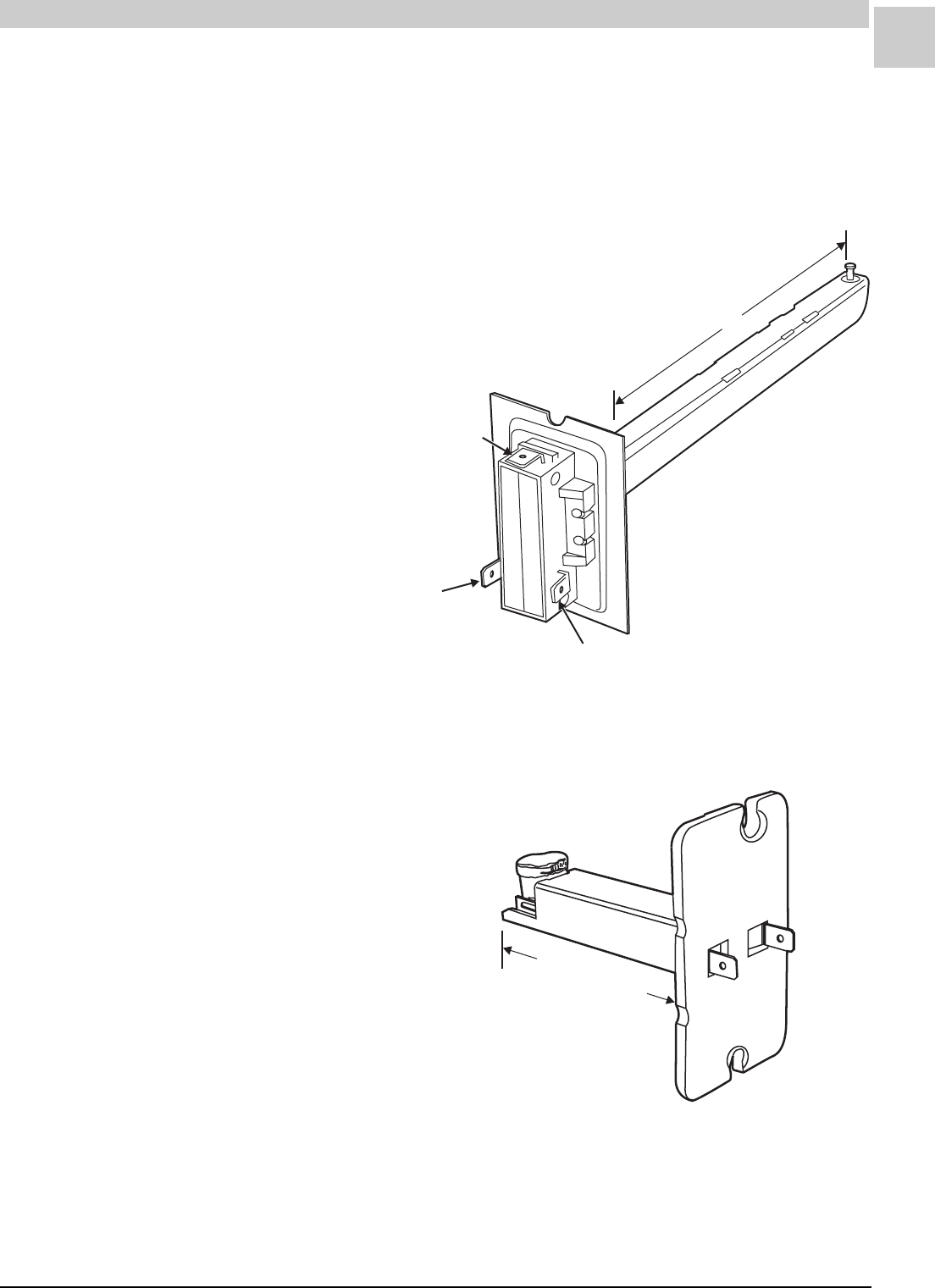
Service Reference Manual UNIT COMPONENTS
5-19
SRM-HW/HWC 2/99
Main (High) Limit Switch (*52)
A Normally Closed control that opens if abnormally high circulating air
temperatures occur. It is an automatic reset control.
Note: Several different main limit switches are used. Refer to the parts
list for the correct limit switch.
N.O. (Normally Open)
Terminal
N.C. (Normally Closed)
Terminal
Common Terminal
7"
FIGURE 5-15 Camstat Main Limit Switch
Camstat Model L59-7B-220-30
Armstrong P/N: 01150A008
Setting: 220°F
FIGURE 5-16 Main Limit Switch
3.05 (+/ .05 )""
Manufacturer P/N: INT17L-2107
Armstrong P/N: 40154B007
Open Setting: 190°F
Closed Setting: 160°F
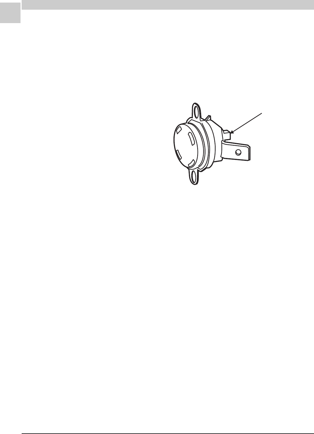
5-20
UNIT COMPONENTS Magic-Pak: HW/HWC
SRM-HW/HWC 2/99
Flame Rollout Switch (*55)
A Normally Closed switch that opens when abnormal temperatures occur
in the burner area, caused by a restricted heat exchanger, causing main
burner flame to “roll out” into the vestibule area.
To reset the switch, push the button on top. The button is a different color
from the body.
Reset Button
FIGURE 5-17 Flame Rollout Switch
Cutout Temperature:
Marked on body of switch
Nominal Switch Contact Rating:
15 A @ 120VAC
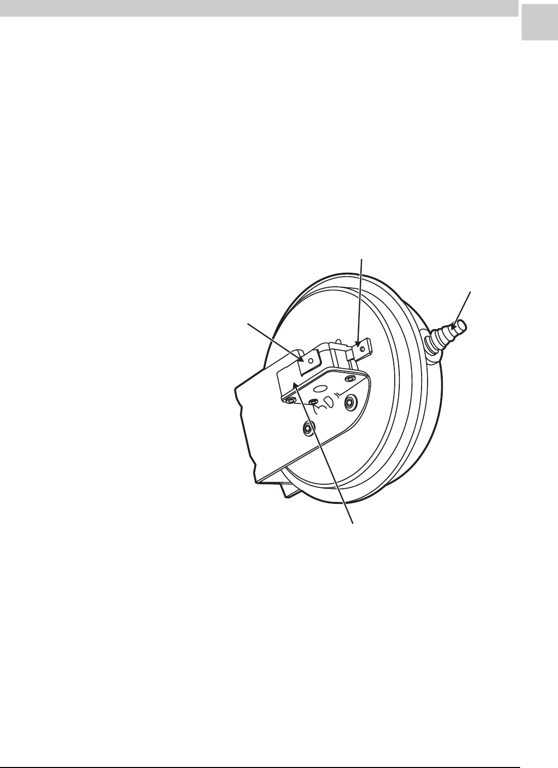
Service Reference Manual UNIT COMPONENTS
5-21
SRM-HW/HWC 2/99
Pressure Switch (*57)
These are Normally Open switches that react to a difference in pressure
on an internal diaphragm. It will not allow ignition to start if the induced
draft blower cannot produce sufficient negative pressure relative to
atmospheric pressure or pressure in a sealed burner box. Its electrical
contacts will open in reaction to inadequate negative pressure resulting
from excessive venting system restriction or a failed induced draft blower,
thus providing protection from a change in safe, stable furnace operation.
The Armstrong part number is stamped on the body of the switch. A label
on the switch carries the manufacturer’s model number. Always verify the
proper switch number from the parts list.
Connect to Port on
Induced Draft Blower
Electrical Switch
Common Terminal
Normally Open
Terminal
FIGURE 5-18 Pressure Switch
Pressure Switch Specifications
Manufacturer: Tridelta Industries
Electrical Rating:
SPDT Elec. Load: 28 VA Pilot Duty @ 24VAC
3 FLA, 18 LRA @ 24VAC
SPST Elec. Load: 5 A Resistive @ 24VAC
Electrical Switch: Single Pole, Normally Open, Snap
Acting Contacts
Electrical Connectors: Common (C), Normally Open
(NO) 1/4" x .032" thick quick connect terminals
Maximum Pressure: 3" W.C.
Operating Temperature Range: – 40° to 190°F
Sample Line Connector: Negative; barb type for use with
3/16" or 1/4" I.D. tubing with .016" +/– .004" bleed hole

5-22
UNIT COMPONENTS Magic-Pak: HW/HWC
SRM-HW/HWC 2/99
TABLE 5-4 Pressure Switches
Pressure Switch Problems
The negative pressure developed in the combustion chamber is directly
related to airflow. During furnace operation, the switch will react to
conditions that reduce airflow, such as: blocked or restricted intake
(combustion air piping), blockage of vent (flue) piping, blockage of the
condensate drain piping, plugged pressure tap ports, leaking hoses or a
failure of the induced draft blower motor.
If the pressure switch has already been replaced and problems are still
being experienced, follow the procedure, Checking Pressure Switch
Operation (found on page 5-24).
If the measured static pressure reading does not meet the switch specifi-
cations, check these items:
1. Pressure switch hose/tubing for cracks or loose connections
2. Induced draft blower wheel for corrosion or loose blades
3. Induced draft blower for tight bearings or loose inducer wheel
gnortsmrA
N/P rodneVrebmuNledoM snepOhctiwS
).C.Wsehcni(
roloC
edoC
100-26814seirtsudnIatledirT9881-A0806SF04.deR
200-26814seirtsudnIatledirT1981-A0806SF72.neerG
300-26814seirtsudnIatledirT0981-A0806SF54.etihW
100-91844seirtsudnIatledirT4162-09001SPP50.–/+52.elpruP
200-91844seirtsudnIatledirT5162-09001SPP50.–/+53.eulB
300-91844seirtsudnIatledirT6162-09001SPP50.–/+54.kniP
400-91844seirtsudnIatledirT7162-09001SPP50.–/+55.deR
500-91844seirtsudnIatledirT8162-09001SPP60.–/+06.neerG
600-91844seirtsudnIatledirT9162-09001SPP60.–/+07.etihW
700-91844seirtsudnIatledirT0262-09001SPP70.–/+08.yarG
800-91844seirtsudnIatledirT1262-09001SPP50.–/+05.deR
900-91844seirtsudnIatledirT2262-09001SPP50.–/+03.egnarO
010-91844seirtsudnIatledirT3262-09001SPP50.–/+01.wolleY
110-91844seirtsudnIatledirT4262-09001SPP50.–/+04.eulBthgiL
210-91844seirtsudnIatledirT5262-09001SPP50.–/+56.nworB

Service Reference Manual UNIT COMPONENTS
5-23
SRM-HW/HWC 2/99
Blocked Intake
Blocked intake is any condition that blocks or restricts the flow of intake
(combustion) air to a point where the pressure fall reaches the calibrated
open setting of the pressure switch.
Potential Causes:
• Rodents
• Spiders
• Nest building in the intake opening
• Debris or trash that has been pulled into the intake opening
Symptoms:
• Excessive negative pressure in the burner box area. The furnace
cycles on and off quite frequently, typically within 60 seconds or so.
• Inability of unit to stay on for a complete call for heat.
For a blocked intake or blocked flue, connect the incline manometer as
shown on in Figure 5-20 on page 5-27 for the specific model groups.
Never try to adjust a pressure switch or jumper the
switch to allow the furnace to operate. Doing so
could allow the furnace to operate under hazardous
conditions, potentially causing property damage,
personal injury or death.
WARNING
DO NOT try to repair a pressure switch. Use an
identical replacement. The use of an improperly
repaired or malfunctioning pressure switch could
result in property damage, personal injury or death.
WARNING
The measured static pressure reading should be compared to the pres-
sure switch specifications. If the measured static pressure meets or
exceeds the specifications and switch contacts will not transfer, check the
following items:
• Switch out of calibration
• Defective pressure switch
• Moisture in pressure switch tubing
• Incorrect switch installed

5-24
UNIT COMPONENTS Magic-Pak: HW/HWC
SRM-HW/HWC 2/99
Blocked Flue
Blocked flue is any condition that blocks or restricts the flue (vent) pipe to
a point where the pressure fall reaches the calibrated open setting of the
pressure switch.
Potential Causes:
• Rodents
• Spiders
• Nest building in the flue pipe
• Outlet screens with excessive restriction
• High wind conditions exceeding 40 mph
Symptoms:
• Low negative pressure on the induced draft (combustion) blower. The
unit cycles on and off quite frequently, typically coming back on within
60 seconds.
• Inability of unit to stay on for a complete call for heat.
Units cycling on pressure switch re-ignite sooner than a main limit switch
can reset.
Tip: With all wiring connected and unit running, use your volt meter
across the pressure switch terminals. No voltage reading = switch closed.
Voltage present = switch open.
Checking Pressure Switch Operation
It is easy to check a pressure switch as it operates within the overall
system. These test procedures make it possible to pinpoint the opening
and closing actions of the pressure switch.
Never try to adjust a pressure switch or jumper the
switch to allow the furnace to operate. Doing so
could allow the furnace to operate under hazardous
conditions, potentially causing property damage,
personal injury or death.
WARNING
DO NOT try to repair a pressure switch. Use an
identical replacement. The use of an improperly
repaired or malfunctioning pressure switch could
result in property damage, personal injury or death.
WARNING
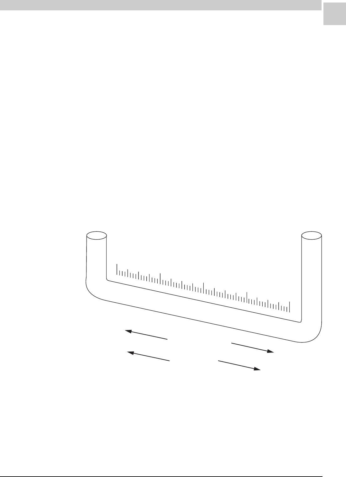
Service Reference Manual UNIT COMPONENTS
5-25
SRM-HW/HWC 2/99
What Is Needed for the Tests
• A good general-purpose incline manometer with a range of 0 - 3"
W.C. (Dwyer 1227 or equivalent).
• Use the parts list to verify that the proper pressure switch is installed
in the unit. Look for the Armstrong part number stamped on the
metal housing. A label on the housing shows the manufacturer’s
model number.
• Find the Switch Open value for the pressure switch in Table 5-4 on
page 22.
• Assorted lengths of plastic tubing and tees to make the connections
to the manometer including the following: 1/8" I.D. high temperature
silicone tubing, 1/4" I.D. vinyl tubing, 1/8" tee and 1/4" tee.
Note: For each procedure, the schematic shows the original factory
tubing with solid black lines. The tees to be installed for pressure
sampling are shown within the dashed circles.
Terminology
Terms related to pressure switch operation and incline manometer testing
are shown below in Figure 5-19.
FIGURE 5-19 Incline Manometer
0
-1"
1" 2"
3"
BA
“Negative” pressure
“Positive” pressure
“Pressure Rise”
“Pressure Fall”

5-26
UNIT COMPONENTS Magic-Pak: HW/HWC
SRM-HW/HWC 2/99
A Word About the “Switch Closed” Value
Switch Closed is the pressure at which the contacts close as the induced
draft blower comes up to speed. It is calculated by adding – 0.1" W.C. to
the sum of the switch’s Open value and its upper tolerance.
For example, for a Armstrong P/N 44819-005 switch:
– 0.1" + (– .60" + – .06") = – 0.76" W.C.
On a system operating correctly, it is likely that the manometer reading
will go to a value that is more than enough to close the switch.
A Word About the “Switch Open” Value
Switch Open is the pressure at which the contacts open as the negative
pressure decreases (pressure fall).
Procedure for Checking Pressure Switch
1. Position the manometer so it can be watched easily during testing.
Balance and zero the manometer according to the manufacturer’s
instructions.
2. Insert a test line with tee between the pressure switch and blower.
One piece of the tubing connects the pressure switch to the fitting at
the back side of the induced draft blower housing. Connect the tee to
the manometer as shown in Figure 5-20.
Note: Always keep the pressure switch in the circuit when measuring.
Switches incorporate internal bleeds to keep moisture out of
the pressure switch line.
3. Using Table 5-4 on page 5-22 and the formula provided above,
calculate the close value for the switch being worked with.
4. Start the furnace to call for heat. Observe the manometer reading
increase (increasing pressure rise) as the induced draft blower
comes up to speed. Ignition should start at a reading that is approxi-
mately the Close value that was earlier determined for the specific
switch in Step 3.
5. With the furnace running in the full heat cycle, observe the pressure
reading. Note this reading and compare it to the Open value shown
for that switch in Table 5-4 on page 5-22.
Using Armstrong P/N 44819-005 pressure switch for an example, the
reading on pressure fall when the contacts open can be between – 0.54"
W.C. and – 0.66" W.C.
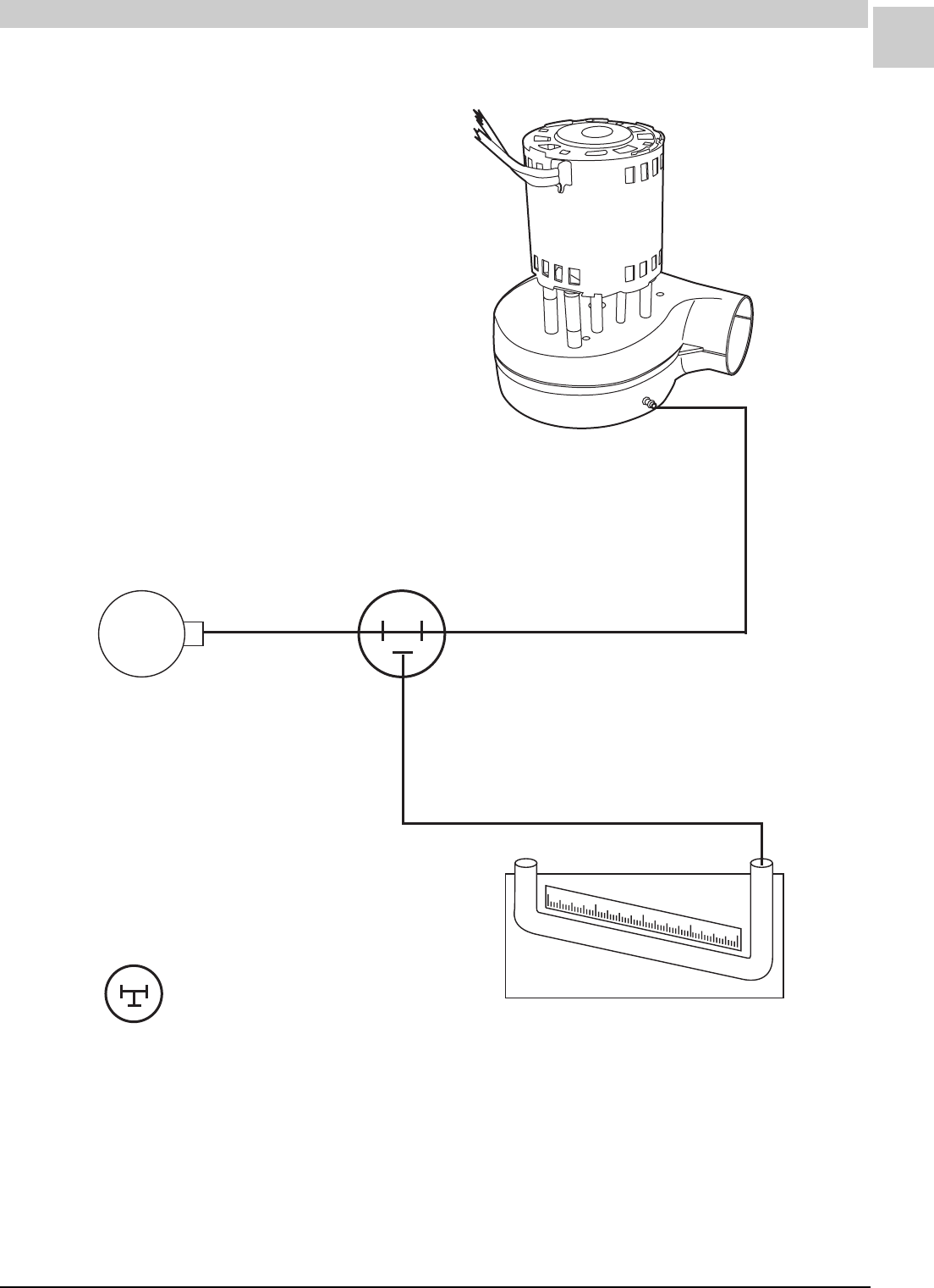
Service Reference Manual UNIT COMPONENTS
5-27
SRM-HW/HWC 2/99
0
-1"
1" 2"
3"
Pressure Switch 1/8" Tee
Induced Draft Blower
BA
Incline Manometer
= Tee installed for test
purposes only
FIGURE 5-20 Incline Manometer Connection

5-28
UNIT COMPONENTS Magic-Pak: HW/HWC
SRM-HW/HWC 2/99
Compressors (*262)
1
2
3
4
5
6
7
8
9
10
11
12
TABLE 5-5 Compressor Specifications (continued on next page)
ledoMepyTrosserpmoC rosserpmoC
ledoM
M/B
)ylnOhesmuceT(
gnortsmrA
N/P
1-321CWH)llA(yratoRhesmuceTDXE2155AKR4A-200-TE-741KR100C80093
1-381CWH)llA(gnitacorpirceRhesmuceTNXE7155FWA4A-980-TE-105WA900C52153
1-342CWH)llA(llorcSdnalepoC031-VFPCK42RZ--500-11824
1-303CWH)llA(llorcSdnalepoC031-VFPCK82RZ--600-11824
6-,7-,9-,11-281CWH)llA(gnitacorpirceRhesmuceTNXE7155FWA4A-980-TE-105WA900C52153
9-,11-242CWH)llA(llorcSdnalepoC031-VFPCK42RZ--500-11824
1-,3-,4-,5-,8-,01-221CWH)llA(yratoRhesmuceTDXE2155AKR4A-200-TE-741KR100C80093
1-,3-,4-,5-,8-,01-242CWH)llA(llorcSdnalepoCVFP1K32RZ--500C63153
9-203CWH)llA(llorcSdnalepoC031-VFPCK82RZ--600-11824
2-,3-,4-,5-,8-281CWH)llA(yratoRhesmuceTDXE8155AKR4A-900-TE-332KR200C80093
1-,3-,4-,5-,8-203CWH)llA(llorcSdnalepoCVFP1K82RZ--100C63153
1-281CWH)llA(llorcSdnalepoCVFP1K81RZ--400C63153

Service Reference Manual UNIT COMPONENTS
5-29
SRM-HW/HWC 2/99
1
2
3
4
5
6
7
8
9
10
11
12
egatloVesahPALRARL nuR
.paC
gnortsmrA
N/P
gnidniW
R/S.seR epyTliO liO
egrahC
noitcuS
eniL
egrahcsiD
eniL
032/8021 3.62073/52200D41583A/NytisocsiV002lareniM.zo21")2/1(05.")61/5(513.
032/8021 3.84073/53400D41583A/NytisocsiV002lareniM.zo23")4/3(357.")8/3(873.
032/80212.310.95073/53400D4158371.1/54.2ytisocsiV002lareniM.zo52")4/3(57.")2/1(05.
032/80217.510.37044/53010D4158339./47.2ytisocsiV002lareniM.zo83")4/3(57.")2/1(05.
032/8021 3.84073/53400D41583A/NytisocsiV002lareniM.zo23")4/3(357.")8/3(873.
032/80212.310.95073/53400D4158371.1/54.2ytisocsiV002lareniM.zo52")4/3(57.")2/1(05.
032/8021 3.62073/52200D41583A/NytisocsiV002lareniM.zo21")2/1(05.")61/5(513.
032/80219.215.26073/03300D4158389./30.3ytisocsiV002lareniM.zo62")4/3(57.")2/1(05.
032/80217.510.37044/53010D4158339./47.2ytisocsiV002lareniM.zo83")4/3(57.")2/1(05.
032/8021 0.54073/52200D41583A/NytisocsiV002lareniM.zo21")8/5(36.")61/5(513.
032/80210.510.67073/53400D4158377./35.2ytisocsiV002lareniM.zo62")4/3(57.")2/1(05.
032/80217.010.05073/52200D4158392.1/19.4ytisocsiV002lareniM.zo42")4/3(57.")2/1(05.
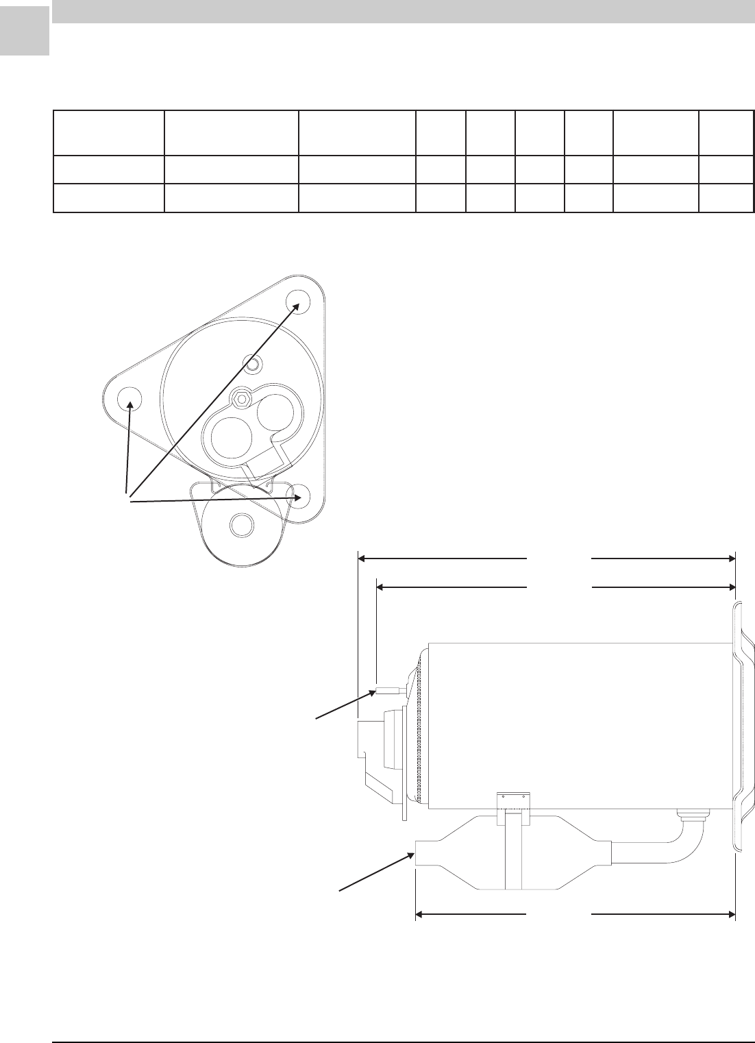
5-30
UNIT COMPONENTS Magic-Pak: HW/HWC
SRM-HW/HWC 2/99
A
B
C
D
I.D. Copper Tube
.(43 - .50"
Suction
" Deep)
.315 I.D.Copper
Tube
"
Discharge
.75 Diameter Holes"
C
SR
Manufacturer: Tecumseh
All measurements in inches unless otherwise specified.
Side View
Top View
TABLE 5-6 Tecumseh Rotary Compressor Specifications
FIGURE 5-21 Tecumseh Rotary Compressor
N/PgnortsmrA ledoMreilppuS
rebmuN
M/BreilppuS
rebmuN ABCD d'qeR.paC
CAV-FDM
liO
).zo(
100C80093DXE2155AKR4A-200-TE741KR26.0160.01005.65.8073/5221
200C80093DXE8155AKR4A-900-TE332KR05.1149.01036.87.8073/5221
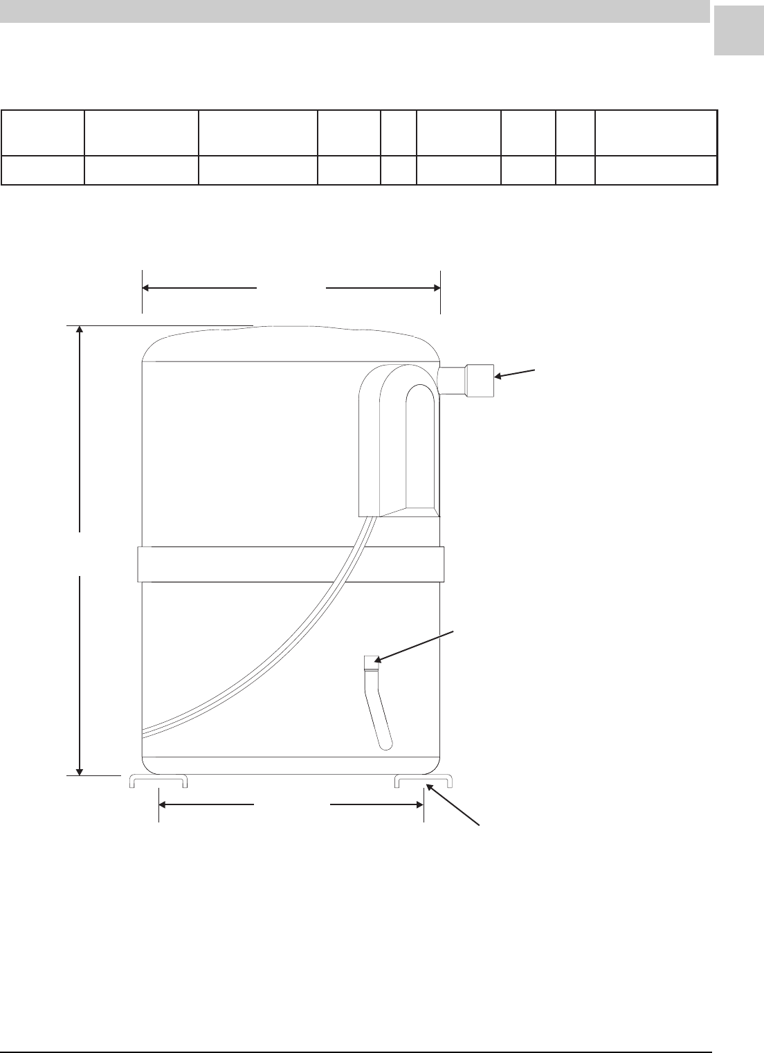
Service Reference Manual UNIT COMPONENTS
5-31
SRM-HW/HWC 2/99
TABLE 5-7 Tecumseh Reciprocating Compressor Specifications
Manufacturer: Tecumseh
.753"/.756" I.D.
Copper TubeSuction
12.647"
12.753”
.378"/.381" I.D. Copper TubeDischarge
7.475"
7.525"
(Between Centers of Holes)
.750 /.760 Diameter
(4 Holes)
""
9.38"
Side View
FIGURE 5-22 Tecumseh Reciprocating Compressor
gnortsmrA
N/P
ledoMreilppuS
rebmuN
M/BreilppuS
rebmuN egatloV.zH esacknarC
retaeH .A.R.L.H.P .paC
d'qeR
900C52153NXE7155FWA4A-980-TE105WA032/80206oN3.841 V073@DFM53
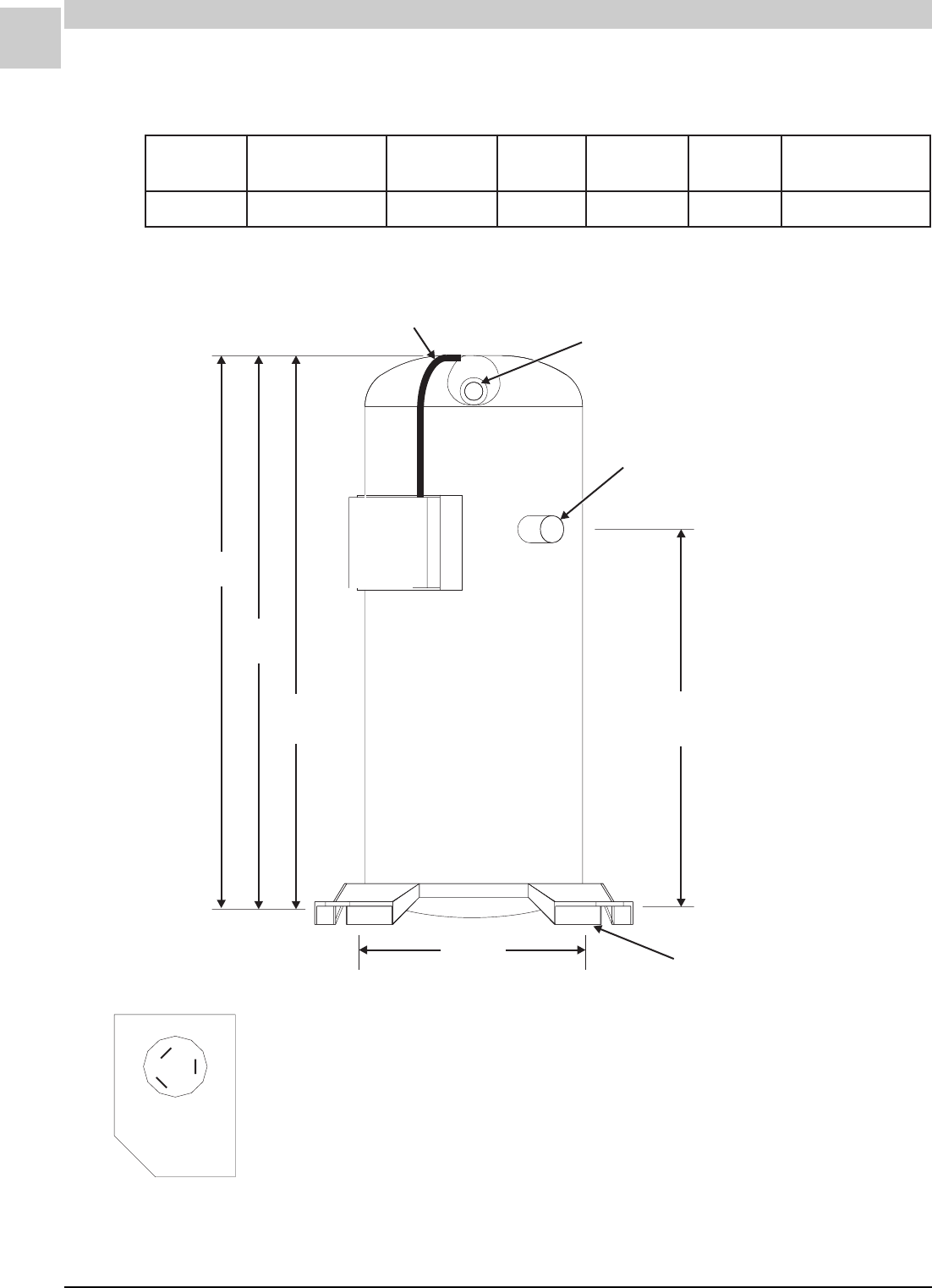
5-32
UNIT COMPONENTS Magic-Pak: HW/HWC
SRM-HW/HWC 2/99
Manufacturer: Copeland
A
B
CD
.500" I.D. Copper TubeDischarge
.750" I.D. Copper-Plated Steel TubeSuction
18 Ga. Thermal Protector Leads
(12.13" Long)
7.50"
(Between Centers of Holes)
.765 Diameter (4 Holes)"
FIGURE 5-23 Copeland Compressor
Side View
C
R
S
T
1
T
2
T
3
All measurements in inches unless otherwise specified.
Typical T’Box
Layout
TABLE 5-8 Copeland Compressor Specifications
gnortsmrA
N/P
ledoMreilppuS
rebmuN ABCD d'qeR.paC
CAV-DFM
100C63153VFP-1K82RZ13.41/60.4123.3159.7/27.736.9073/53
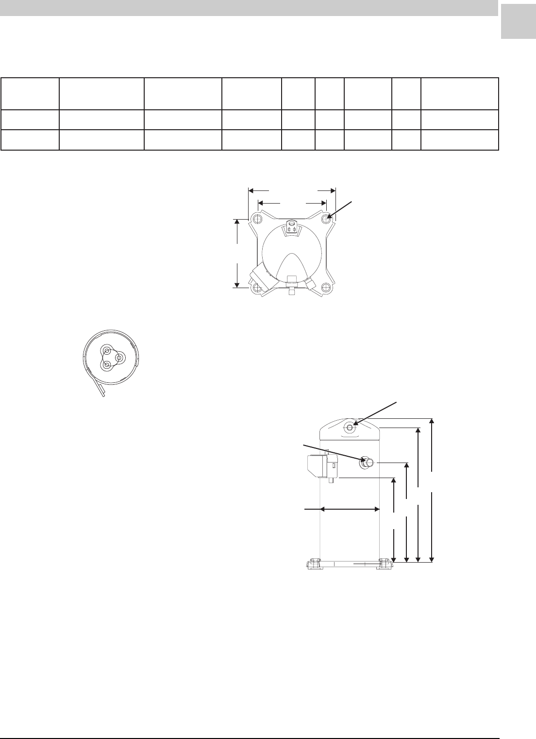
Service Reference Manual UNIT COMPONENTS
5-33
SRM-HW/HWC 2/99
Manufacturer: Copeland
C
S
R
T
1
T
3
T
2
9.41 /9.62""
7.50"
(Typ.)
7.50"
(Typ.)
.750 Dia.
(4 Holes)
"
A
B
C
D
.500" I.D. Copper
Discharge Fitting
.750" I.D. Copper-Plated
Steel Suction Fitting
E
FIGURE 5-24 Copeland Compressor
Side View
Top View
Top View
All measurements in inches unless otherwise specified.
TABLE 5-9 Copeland Compressor Specifications
gnortsmrA
N/P
ledoMreilppuS
rebmuN
gnitaR
zH-HP-egatloV ABCDE d'qeR.paC
CAV-DFM
500-11824031-VFP-CK42RZ06-1-032/80254.41/12.4123.3136.977.8/35.874.5073/53
600-11824031-VFP-CK82RZ06-1-032/80254.41/12.4123.3136.979.725.6073/53
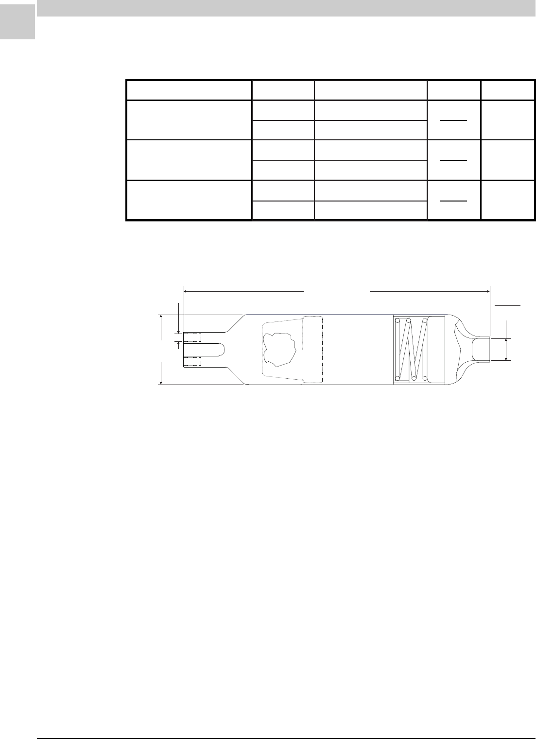
5-34
UNIT COMPONENTS Magic-Pak: HW/HWC
SRM-HW/HWC 2/99
Drier-Filters (*301)
.314"
.317"
4.38" +/– .13"
1.00"
B - # Holes
A - I.D. I.D.
FIGURE 5-25 Drier-Filter
Armstrong Part Number
39059B001
39059B002
39059B003
AB
.108"
.111"
.114"
.117"
.108"
.111"
2
3
4
TABLE 5-10 Drier-Filter Specifications
reilppuSrebmuNtraPreilppuS
ocnipS1-703001
rekraP00-151230
ocnipS2-703001
rekraP00-051230
ocnipS3-703001
rekraP00-181230

Service Reference Manual UNIT COMPONENTS
5-35
SRM-HW/HWC 2/99
HWC Capillary Tubes (*256)
* All part numbers provided are Armstrong part numbers.
** See page 5-34 for drier information.
*** See the figures beginning on page 5-36 for detailed drawings of the capillary tubes.
TABLE 5-11 HWC Capillary Tube Specification Tables*
sledoMreirD+.yssA**ylnOreirD***ylnOsebuT.paC .paC.dnI
ebuT
.paC
.D.I
.paC
.D.O
.paC
htgneL
#
sebuT
1-321100-17234100B95093100-76234100B20350"450.0"601.0"532
1-381200-17234200B95093200-76234520B20350"450.0"601.0"443
1-342300-17234200B95093300-76234420B20350"950.0"211.0"643
1-303100-57334300B95093100-08234,100-18234520B20350"450.0"601.0"444
01-221100-17234100B95093100-76234100B20350"450.0"601.0"532
8-ot1-221100B85093100B95093100B20193100B20350"450.0"601.0"532
9-ot1-281200B85093200B95093200B20193520B20350"450.0"601.0"443
8-ot4-242300B85093200B95093300B20193420B20350"950.0"211.0"643
11-ot9-242300-17234200B95093300-76234420B20350"950.0"211.0"643
3-ot1-203100B75093300B95093100B89293,100B30193520B20350"450.0"601.0"444
8-ot4-203100-05604300B95093100-15604,100-25604520B20350"450.0"601.0"444
9-203100-57334300B95093100-08234,100-18234520B20350"450.0"601.0"444
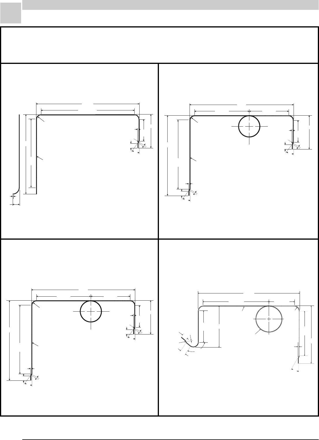
5-36
UNIT COMPONENTS Magic-Pak: HW/HWC
SRM-HW/HWC 2/99
30°
.75"
.25" Rad.
I.S. Typ.
.13"
.08"
3.81"
Ref.
6.00"
11.89" Ref.
14.00"
1.00 Rad. Typ."
5302B001 - 2 Req’d
14.88"
12.77"
Ref.
1.78"
.73"
Ref.
3.500 Diameter
1Turn
2.875 Diameter Mandrel
"
"
30°
.75"
.25" Rad.
I.S. Typ.
.13"
.12"
3.50"
Ref.
5.43"
6.75" Ref.
7.25" Ref.
15.60"
.75 Rad. Typ."
5302B025 - 3 Req’d
.13"
30°
.75" .12"
12.82"
10.88"
Ref.
3.500 Diameter
1Turn
2.875 Diameter Mandrel
"
"
30°
.75"
.25" Rad.
I.S. Typ.
.13"
.12"
3.63"
Ref.
5.57"
6.50" Ref.
9.00" Ref.
17.11"
.75 Rad. Typ."
5302B024 - 3 Req’d
.13"
30°
.75" .12"
13.19"
11.25"
Ref.
4.38"
Ref.
.13" Typ.
2.500" Diameter
2 Turns
2.125" Mandrel
30°
5.46"
.75 Rad.
Typ.
"
5.25 Ref."9.00" Ref.
15.86"
4.23"
2.62"
Ref.
.75" Ref.
130°
.250" Rad.
Typ.
.75" Typ. .12"
Typ.
5302B025
2 Req’d
Notes:
• All bends 90° unless otherwise noted.
• Do not kink or flatten during forming.
• Tape tubes together with masking tape.
FIGURE 5-26 43267-001 Capillary Tubes FIGURE 5-27 43267-002 Capillary Tubes
FIGURE 5-28 43267-003 Capillary Tubes FIGURE 5-29 43280-001 Capillary Tubes
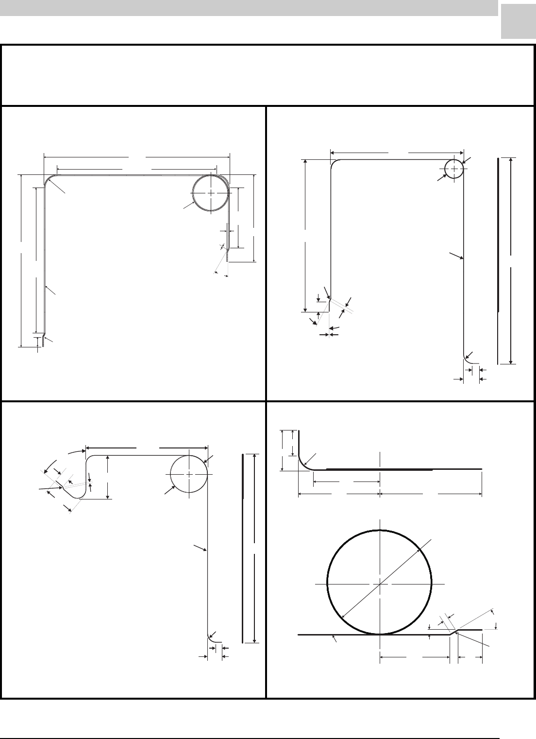
Service Reference Manual UNIT COMPONENTS
5-37
SRM-HW/HWC 2/99
30°
4.25"
Ref.
6.16"
.13" Typ.
.12" Typ.
13.13" Ref.
14.74"
3.500" Diameter
1Turn
3.00" Mandrel
11.00"
Ref.
12.91"
.25" Rad. I.S. Typ.
53025B025 - 2 Req’d
.75" Typ.
.75" Rad. Typ.
10.70"
1.446 Diameter"
1.25
Tur ns
5302B025 - 2 Req’d
.750 Rad.
Typica l
"
1.28"
.50" +/– .13"
16.40"
12.22 +/ .13" "
.75"
.13"
.08"
30°
.250"
Rad. I.S.
Typica l
16.40"
1.25
Turns
5302B025 - 2 Req’d
.750" Rad.
Typical
1.28"
.50" +/– .13"
10.70"
3.196" Diameter
3.81"
2.73"
.75"
.08"
50°
.250 Rad. I.S.
Typical
"
3.688 Diameter
3 Turns
"
5302B025 -2 Req’d
2.50" .75"
.25 Rad. I.S. Typ."
.13"
.08"
30°
3.05" 3.60"
2.25"
.75"
1.55" .75" Rad.
Notes:
• All bends 90° unless otherwise noted.
• Do not kink or flatten during forming.
• Tape tubes together with masking tape.
FIGURE 5-30 43281-001 Capillary Tubes FIGURE 5-31 40651-001 Capillary Tubes
FIGURE 5-32 40652-001 Capillary Tubes FIGURE 5-33 39103B001 Capillary Tubes
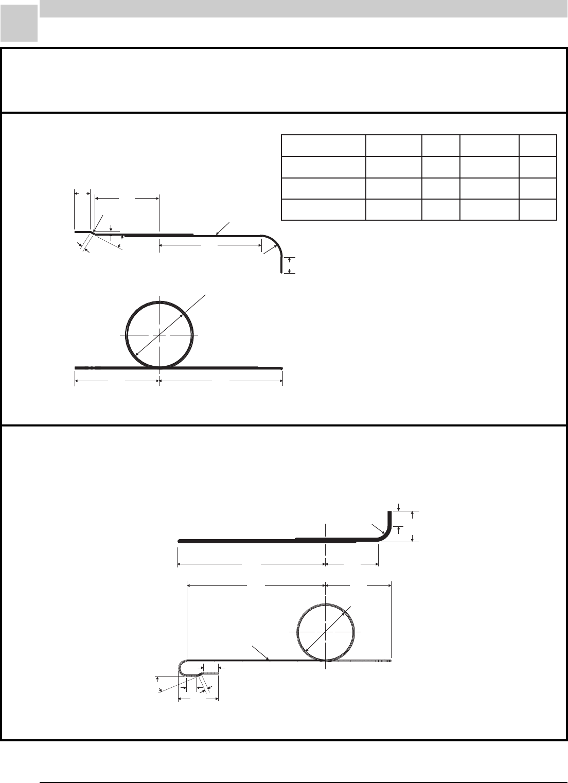
5-38
UNIT COMPONENTS Magic-Pak: HW/HWC
SRM-HW/HWC 2/99
A - Diameter
B - Turns
4.64" 6.76"
.75"
1.25"
C - D Req’d
.75" 2.79"
.13"
.25" Rad. I.S.Typ.
.08"
30° 5.42"
2.844" Diameter
3 Turns
53205B025 - 2 Req’d
7.00" 3.30"
7.43" 2.50"
.75" Rad. Typ. 1.55"
.75"
.75"
.50"
2.03"
.08"
30°
Notes:
• All bends 90° unless otherwise noted.
• Do not kink or flatten during forming.
• Tape tubes together with masking tape.
TABLE 5-12 39102B001 Specifications
FIGURE 5-34 39102B001 Capillary Tubes
FIGURE 5-35 39298B001 Capillary Tubes
N/PgnortsmrAABCD
100B20193"035.32 100B20352
200B20193"182.33 520B20353
300B20193"005.33 420B20353
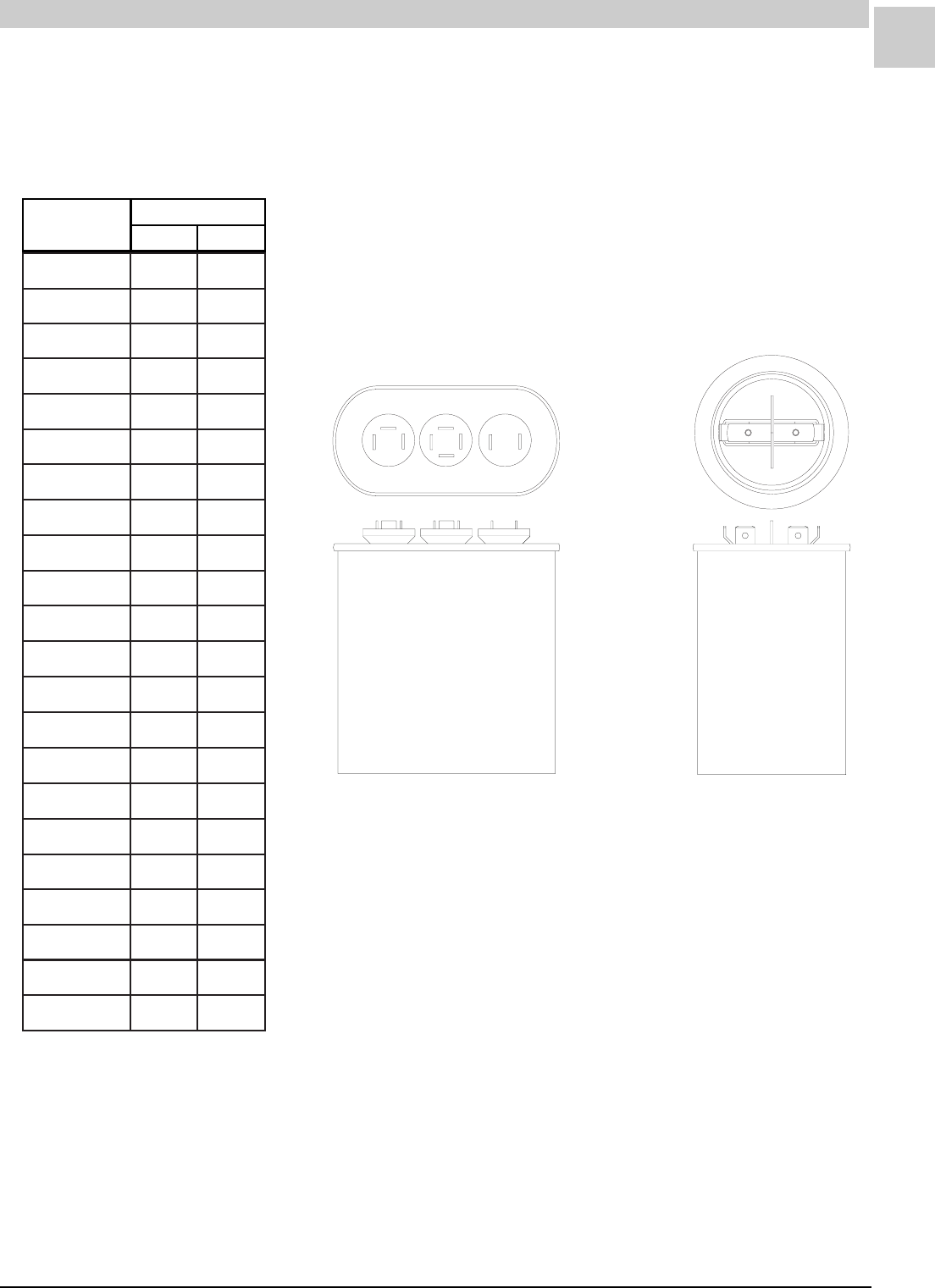
Service Reference Manual UNIT COMPONENTS
5-39
SRM-HW/HWC 2/99
Capacitors (*271)
FIGURE 5-36 Capacitors
Dual Single
Armstrong
P/N
Rating
Volts
MFD
TABLE 5-13 Capacitor Ratings
100D415835/02073
200D415835/52073
300D415835/03073
400D415835/53073
500D415835/04073
600D415835/04044
700D415835.7/04044
800D415835.7/54044
900D415835.7/53044
010D415835/53044
110D415835/54073
210D415835.7/55044
310D415835.7/06073
410D415835.7/08073
510D415835/54044
610D415835/06073
710D415835/08073
810D415835/05073
910D415835.7/05044
020D415835/55073
120D415835/07073
220D415835/06044

5-40
UNIT COMPONENTS Magic-Pak: HW/HWC
SRM-HW/HWC 2/99
Evaporator Blower Motor -
Indoor Blower (*69)
• FLA and capacitor ratings may vary. Always check FLA and
capacitor ratings on the motor data plate.
• Motor diameter - 5.70", shaft size - .50", rotatin - CW lead end
• See parts list for correct selection of motor and capacitor.
Condenser Fan Motor -
Outdoor Motor (*267)
Notes:
TABLE 5-14 Evaporator Blower Motor Specifications
gnortsmrA
N/P
ALF
)hp/zh/v( MPR fo#
sdeepS PHroticapaC
100B54093 1.1 )1/06/032-802( 000136/1073/4
100B64093 3.2 )1/06/032-802( 021133/1073/5.7
• FLA and capacitor ratings may vary. Always check FLA and
capacitor ratings on the motor data plate.
• Motor diameter - 5.70", shaft size - .50", rotatin - CW lead end
• See parts list for correct selection of motor and capacitor.
Notes:
TABLE 5-15 Condenser Fan Motor Specifications
gnortsmrA
N/P
ALF
)hp/zh/v( MPR fo#
sdeepS PHroticapaC
100B44093 8.1 )1/06/032-802( 570114/1073/5
100B48093 9. )1/06/032-802( 570118/1073/5
100-28214 9. )1/06/032-802( 570118/1073/5
100-45214 8.1 )1/06/032-802( 570114/1073/5
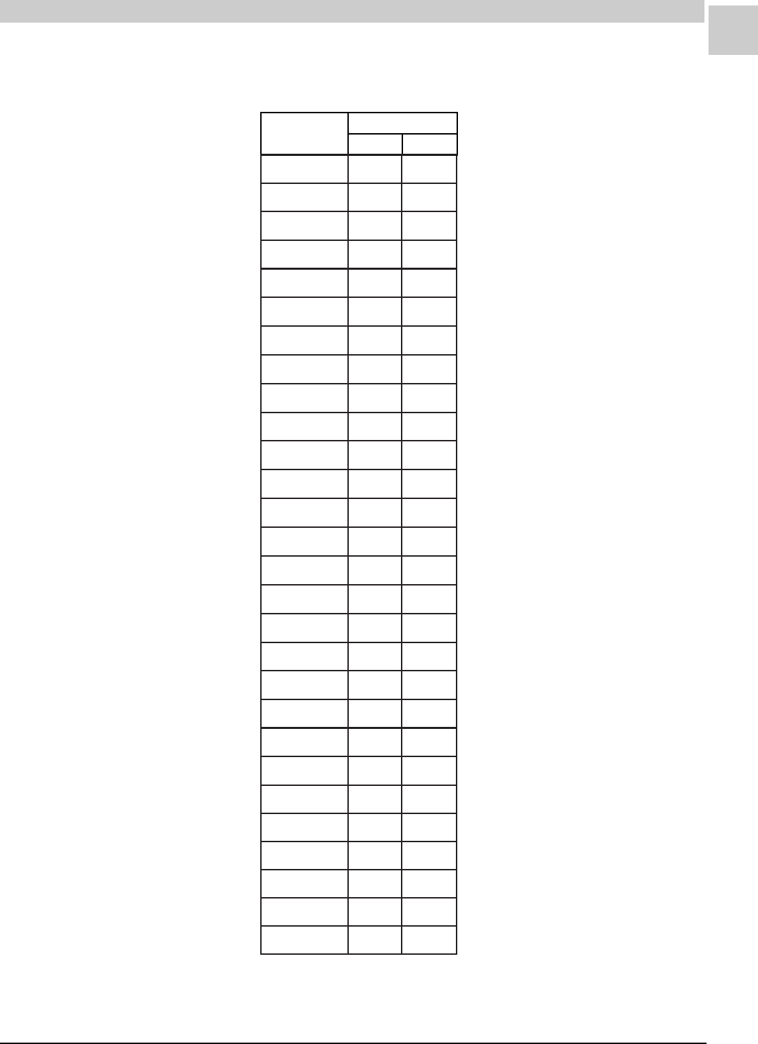
Service Reference Manual UNIT COMPONENTS
5-41
SRM-HW/HWC 2/99
Capacitors-Run (*86)
Armstrong
P/N
Rating
Volts
MFD
TABLE 5-16 Run Capacitor Ratings
100D100434073
200D100435073
300D100436073
400D100435.7073
500D100438073
600D100438044
700D1004301073
800D100435.21073
900D1004351044
010D1004302044
110D1004352073
210D1004352044
310D1004303044
410D1004353073
510D1004353044
610D1004304073
710D1004304044
810D1004354044
420D1004351073
520D1004302073
620D1004303073
720D1004301044
820D1004302073
920D1004352073
030D1004303073
130D1004353073
230D1004304073
330D1004355044
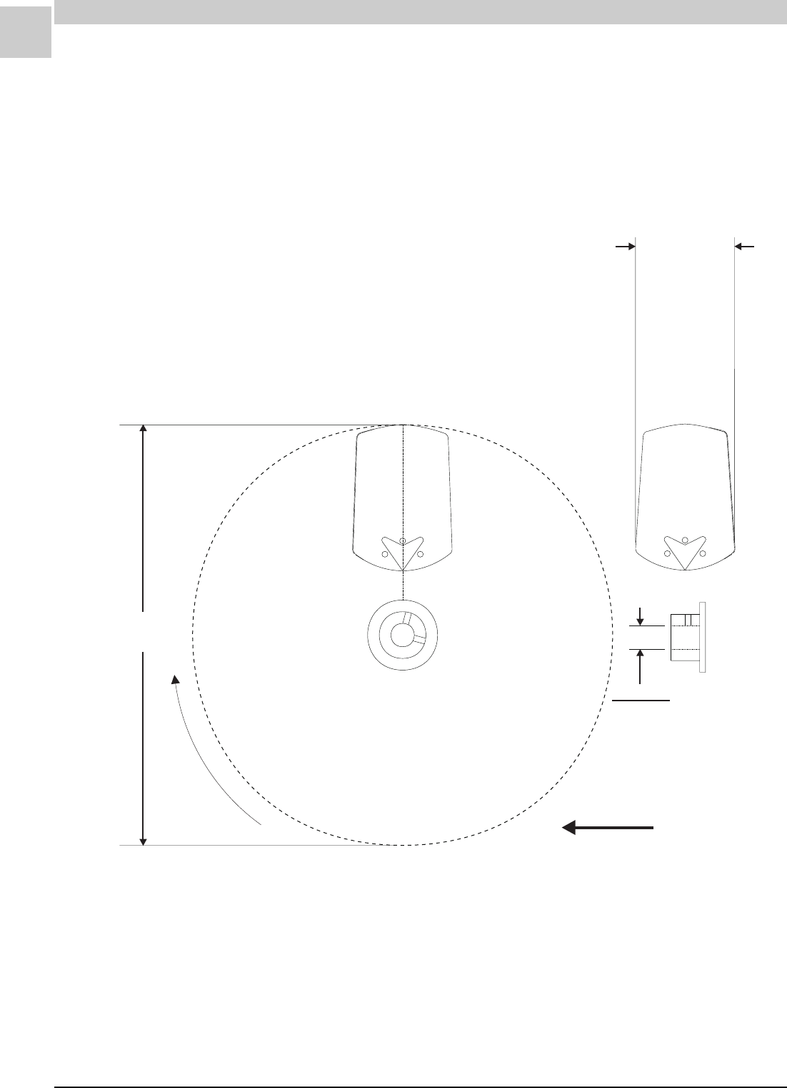
5-42
UNIT COMPONENTS Magic-Pak: HW/HWC
SRM-HW/HWC 2/99
Fan Blades (*268)
18.00 +/ .06" "
AIR FLOW
Rotation
Diameter Bore
.5002"
.5019"
3.79 +/ .09" "
Notes:
1. 26° Pitch, 5 Blades
2. Material: 24 Ga. Galvalume
3. Set Screw: (2) 5/16"-24 x 5/8" long square head, cup point
FIGURE 5-37 Fan Blades - HWC Models 122, 182 & 123, 183
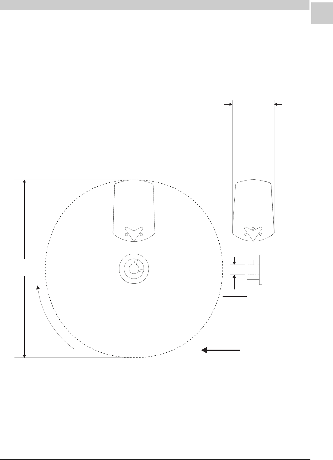
Service Reference Manual UNIT COMPONENTS
5-43
SRM-HW/HWC 2/99
18.00 +/ .06" "
AIR FLOW
Rotation
Diameter Bore
.5002"
.5019"
3.59 +/ .09" "
Notes:
1. 24° Pitch, 3 Blades
2. Material: 24 Ga. Galvalume
3. Set Screw: (2) 5/16"-24 x 5/8" long square head, cup point
FIGURE 5-38 Fan Blades - HWC Models 242, 302 & 243, 303
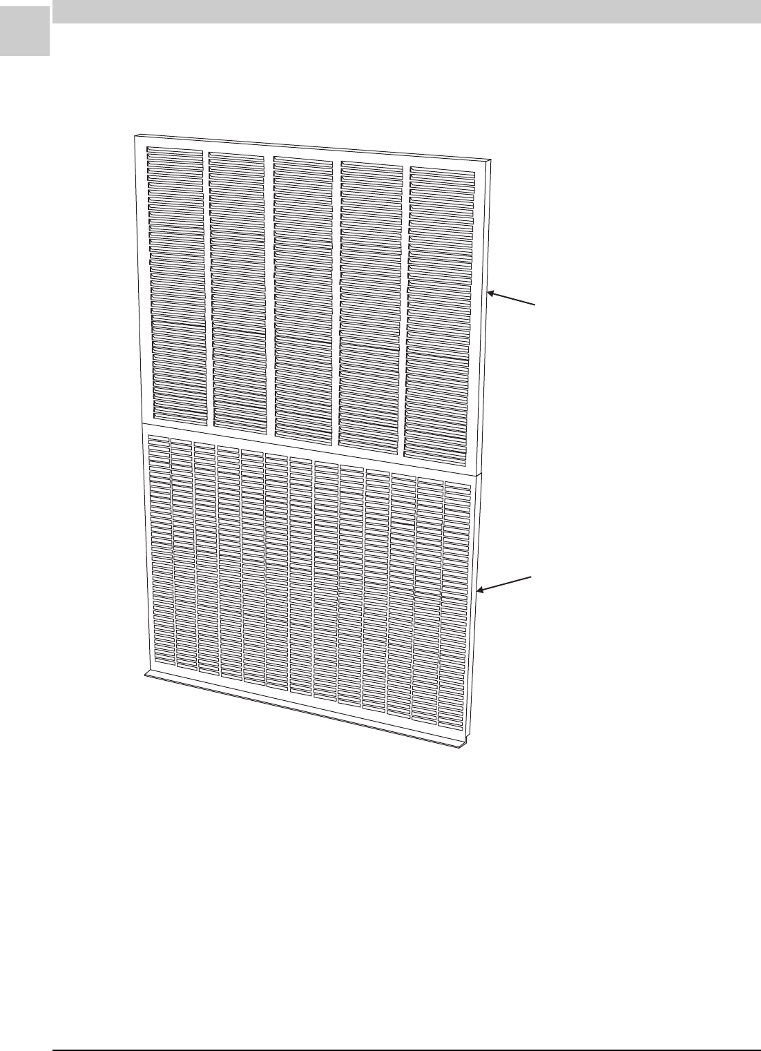
5-44
UNIT COMPONENTS Magic-Pak: HW/HWC
SRM-HW/HWC 2/99
Lower Grill Panel
Armstrong P/N 03551D100
Upper Louver Panel
Armstrong P/N 03545C000
Exterior Grill Panels
(Not Listed in the Parts Lists)
Refer to the Component Location Illustrations section beginning on page
4-1 for further detail of the exterior grill panels and other panels.
FIGURE 5-39 Exterior Grill Panels

Service Reference Manual INSTALLATION
6-1
SRM-HW/HWC 8/99
Section 6 - Installation
Location .............................................. 6-3
Installing With Wall Sleeve.................... 6-5
Installing Without Wall Sleeve ............... 6-6
Support............................................... 6-6
Condensate Drain ................................. 6-7
Venting ............................................... 6-7
Removal of Unit from Common
Venting System .................................... 6-9
Gas Connections .................................. 6-9
Electrical Connections ........................ 6-11
Thermostat ....................................... 6-12
Supply and Return Ducts .................... 6-12
Air Filter ........................................... 6-13
Adjustments (Heating Section) ............ 6-13
Adjustments (Cooling Section) ............. 6-14
Blower .............................................. 6-14
Limit Control ..................................... 6-14
High Altitude Adjustments (U.S.) ......... 6-14
High Altitude Adjustments (Canada)..... 6-14

6-2
INSTALLATION Magic-Pak: HW/HWC
SRM-HW/HWC 8/99
Installation and Operation in Extremely
Cold Weather Areas ........................... 6-15

Service Reference Manual INSTALLATION
6-3
SRM-HW/HWC 8/99
Installation
Information in this section is provided for the convenience of the service
technician, for the purpose of evaluating the installation during service
and troubleshooting. It does not take the place of the complete Arm-
strong Installation and Maintenance Instructions that are shipped with
every Magic-Pak unit. If you are installing an Armstrong product and
need a copy of the Installation and Maintenance Instructions, consult the
table below and contact the Armstrong factory.
IMPORTANT:
READ THIS FIRST
Location
Magic-Pak HW/HWC units are designed and certified for through-the-wall
installations only and must not be installed in any other type of applica-
tion. The interior portions of the unit may be surrounded by a closet with
clearances to combustible material held to 0" at sides, 2" top and 1" front
and plenum. Adequate clearance must be provided to install the union
and manual shutoff valve as well as providing accessibility to the field
wiring junction box. Do not install directly on carpeting, tile or other
combustible material other than wood flooring.
Magic-Pak HW/HWC units should be installed in an outside building wall
that is clear of obstructions which might impede the free intake and
discharge of condenser air.
A building wall should be no closer to an opposite building wall than 2' for
every floor or Magic-Pak unit in a vertical array facing the wall. For
example, a one-story building with a Magic-Pak HW/HWC unit should be
a minimum of 2' from the wall facing the unit, and if the facing wall also
has a Magic-Pak unit, the two walls should be at least 4' apart.
A six-story building with six Magic-Pak units in a vertical array should be
at least 12' from the opposite building wall, and if that building wall also
contains Magic-Pak units, the building should be at least 24' apart.
Buildings taller than six stories need not exceed the separation needed
for six-story buildings.
TABLE 6-1 HW/HWC Installation and Maintenance Instructions
gnortsmrA
noitacilbuP
N/P
etaDnoitpircseD
990B2405499/2 1-)303,342,381,321(CWH)llA( draoB7901hceTU/w9-WH&
790G5209379/7 )303,342,281,221(CWH)llA( WH&5-,6-,7-,8-,9-,01-,11- draoBD1642lawneF/w
490G5209349/7 )303,342,281,221(CWH)llA( WH&1-,2-,3-,4- draoB92-50lawneF/w

6-4
INSTALLATION Magic-Pak: HW/HWC
SRM-HW/HWC 8/99
If three or more adjacent walls form an air shaft with Magic-Pak HW/HWC
units facing each other in each wall, the separation between opposite
walls should be increased by 20%.
These “rule-of-thumb” dimensions are intended to minimize possibilities
for recirculation of condenser air, or interaction between units. However,
these numbers are not exact for every application, and other consider-
ations might suggest that the designer consult the factory about desired
alternatives.
The grille side of the unit may be flush with, or extend beyond, the face of
the exterior wall, but should not be recessed more than 2" from the face
of the building and should not be obstructed with trees, landscape materi-
als or building structure.
There is no minimum clearance required on locating the unit to an interior
corner of a building.
Due to the through-the-wall design, HW/HWC units will always have some
portion of the unit cabinet extending into the interior of the building. The
amount of cabinet exposed to the interior will depend on the wall thick-
ness and the depth the unit is installed into the wall.
Often mechanical rooms and closets are designed into the building
structure to accommodate the interior portions and duct connections.
These rooms or closets must allow ample clearance for regular service
and maintenance.
A 30" wide minimum clearance opening is required in front of the filter
access door. This will allow for easy removal of the door and replacement
of the filter. Electrical conduit, gas lines, duct work and building structures
places within this opening will complicate removal of the filter access door
that may result in a lack of proper maintenance and diminished perfor-
mance.
The cooling section of an HWC unit is built on a sliding chassis that can
only be removed through the filter access door. Any service that must be
done to the condenser section, evaporator fan or refrigeration circuit
requires removal of the chassis from the unit. Therefore, a 30" horizontal
minimum clear opening is required in front of the filter access door to
facilitate removal of the entire cooling chassis.
It is recommended that the doorway to any closet or room containing a
Magic-Pak HW/HWC unit be a minimum of 36" wide to allow some
tolerance for chassis removal and service.
If the unit is installed in a residential garage, it must be located or pro-
tected to avoid physical damage by vehicles. This unit must be installed
so that no electrical components are exposed to water.
Installing units in a relatively inaccessible location for easy chassis
removal should be avoided, if for no other reason than to keep the air filter
accessible for easy and timely cleaning by the occupants or maintenance
personnel.
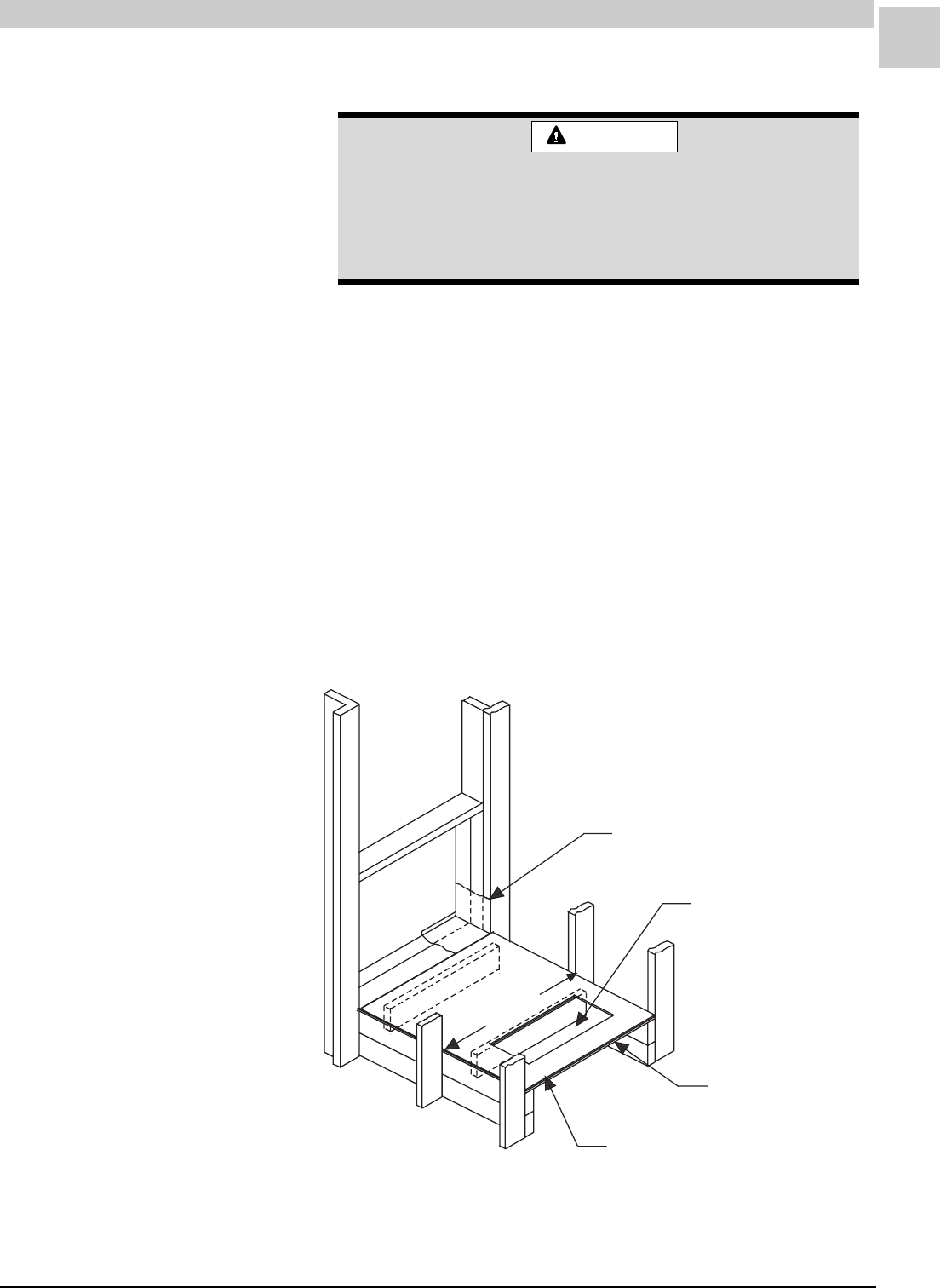
Service Reference Manual INSTALLATION
6-5
SRM-HW/HWC 8/99
Installing With a Wall Sleeve
FIGURE 6-1 HW/HWC Installation
Refer to the installation instructions packed with the wall sleeve and
Figure 6-1 for guidance in assembly and mounting using a wall sleeve.
See also the Accessories section beginning on page 7-3 for further
details on wall sleeve installations.
Refer to page 6-6 for information concerning additional support under the
HW/HWC unit.
Make sure the gaskets attached to the sleeve are not damaged.
Seal the space between the wall sleeve and the building opening with
non-hardening caulking compound. The seal must be weathertight to
prevent entrance of moisture and water into the building.
Assure that the unit is completely seated against the gaskets on the wall
sleeve.
The sleeve is not intended as the sole support for the
unit. Additional support must be provided near the
return opening on the unit for adequate support. The
use of vibration isolation material between the unit and
the support is recommended.
CAUTION
Wall Sleeve
FLOOR
6" X 22" Minimum Opening to
Align with Return Air Opening
In Unit.
Vibration Isolating Material
Plywood
28" Min.

6-6
INSTALLATION Magic-Pak: HW/HWC
SRM-HW/HWC 8/99
Installing Without a Wall Sleeve
Refer to the following directions and Figure 6-1 on page 6-5 for guidance
in installing the unit without a wall sleeve:
1. Measure the size of the unit and provide an opening in an outside
wall that will accept the unit. Local ordinances may require a steel
lintel to support the wall above the opening. The opening must be
square in all four corners.
2. Position the unit so that the grilles on the outside face of the unit are
flush or extend beyond the face of the exterior wall, but not recessed
more than 2" from the face of the building. Provide a support
under the unit, inside the building. Make sure that the inside
support does not block the return air. The unit should be installed
level or pitched slightly to the outside of the building so that rain water
will drain away.
3. Seal the space between the unit and building opening using a non-
hardening caulking compound. The seal must be weathertight to
prevent entrance of moisture and water into the building. Make sure
the drain holes in the base are not plugged with caulking.
Support
In general, the wall sleeves will support the Magic-Pak HW/HWC units on
any wall. The wall, however, must be adequate to support the unit.
Otherwise, one must provide additional support between the unit and the
floor. The center of gravity is between the bottom return-air opening rear
flange and the wall sleeve. When additional support for the unit is desir-
able, it should be near this center of gravity and applied evenly across the
bottom of the unit through adjustable legs to the floor.
A supplementary support can be made for this purpose. It should consist
of two steel channels, 28" long, one placed under the unit and one on the
floor. They are separated by 3/4" pipe and “all-thread” rod, with nuts and
washers, to provide the adjustment pressure. Vibration-isolation blocks or
pads are also required to minimize transmission of vibration into the floor.
Even though the wall may be adequate to support the unit, experience
has shown the desirability of supplementary support to reduce the
possibility of vibration being transmitted into the wall and to other parts of
the structure.
Two 1" diameter holes are located near the front of the Magic-Pak HW/
HWC units, on either side of the return-air opening. These holes are
intended to allow a condensate drain tube to exit the return-air duct cavity
whenever a closed return duct and flexible collar are used. These
should not be used to support the unit. The sheet metal in the
cabinet in this area is not heavy enough to act as a support without
distorting and interfering with proper retention of the filter access cover.
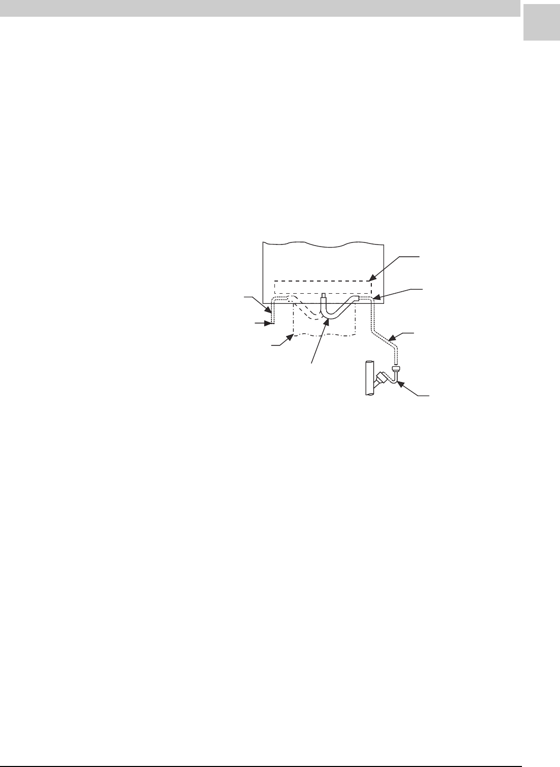
Service Reference Manual INSTALLATION
6-7
SRM-HW/HWC 8/99
Condensate Drain (HWC Models)
Install the plastic drain tube (furnished) over the 5/8" O.D. fitting welded to
the center of the condensate pan. Connect the other end of the drain
tube to the open trap (see Figure 6-2). The plastic drain connection is
provided so that it may be disconnected from the permanent drain tubing
in the building in the event it becomes necessary to remove the cooling
chassis assembly.
The drain line should pitch gradually downward at least 1" per 10 feet of
horizontal run to the open drain trap.
Be certain that the plastic drain tube has free drainage and is not crimped
or flattened at any bend.
Drain Pan
Top of Drain Tube
Must be Below
Bottom of Drain Pan
Drain Tube - Pitch 1" for
every 10 ft. (Installer
Supplied)
Open Drain Trap
5/8" I.D.
Plastic Tube
(Furnished)
Return Air Duct
To Open Drain Trap
Alternative Method
FIGURE 6-2 HWC Drain Installation
Venting
The venting system is an integral part of the appliance. The
venting system must not be modified or added on to.
HW/HWC units are direct vent forced air central furnaces which draw
fresh air from outside through a combustion air opening beneath the vent
into the combustion chamber. The combustion products are then drawn
out of the heat exchanger by an exhaust fan and are forced to the out-
doors.
No special provisions are required for supplying combustion air.
The vent outlet must not be altered or extended in any way.
This appliance should be installed in a location such that the vent system
complies with the National Fuel Gas Code Z223.1 or CAN/CGA-B149.1 &
.2.
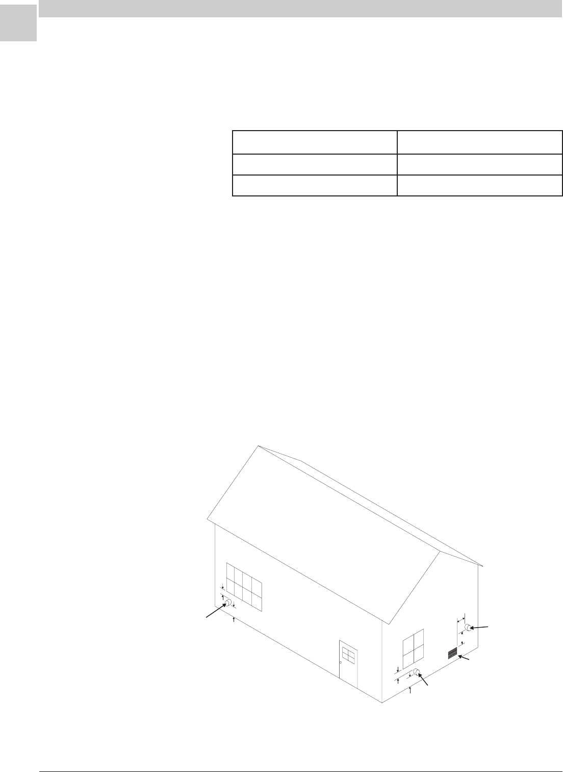
6-8
INSTALLATION Magic-Pak: HW/HWC
SRM-HW/HWC 8/99
The vent system must also terminate at least 3 feet above any forced air
inlet within 10 feet of it.
These clearances do not apply to the combustion air inlet of the appliance
because the combustion air does not enter the air of the building.
Clearance to windows applies to openable windows and not to windows
constructed only of glass with no movable parts such as picture windows.
The vent system must terminate a minimum horizontal distance of 4 feet
away from public walkways, electrical meters, regulators and relief
equipment.
The venting system is designed for proper operation under all weather
conditions and for winds up to 40 m.p.h.
Figure 6-3 shows the required clearances of direct vent to building air
inlets.
Special provisions must be made concerning the location of the vent
termination with relation to building air inlets. A building air inlet is consid-
ered to be any door, moveable window, gravity fresh air inlet or other
opening where fresh outdoor air can be brought into the building. See
Table 6-2 for the clearances required.
9"
12 min"
Direct Vent Terminal
10,000 - 50,000 Btu/hr
Direct Vent Terminal
more than 50,000 Btu/hr
12"
12" min
3min'
Less than
10'
Direct Vent
Terminal
Forced Air Inlet
FIGURE 6-3 Required Clearances for Direct Vent Terminals
TABLE 6-2 HW/HWC Installation and Maintenance Instructions
stinUecnaraelC
CWH/WH83,62sehcnI9
CWH/WH46,15sehcnI21

Service Reference Manual INSTALLATION
6-9
SRM-HW/HWC 8/99
Removal of Unit from Common Venting
System
When an existing furnace is removed from a common venting system
serving other appliances, the venting system is likely to be too large to
properly vent the remaining attached appliances. The following test
should be conducted with each appliance while the other appliances
connected to the common venting system are not in operation.
1. Seal any unused openings in the common venting system.
2. Visually inspect the venting system for proper size and horizontal
pitch and determine there is no blockage or restriction, leakage,
corrosion or other deficiencies which could cause an unsafe condi-
tion.
3. Insofar as is practical, close all building doors and windows between
the space in which the appliances remaining connected to the
common venting system are located and other spaces in the building.
Turn on clothes dryers and any appliance not connected to the
common venting system. Turn on exhaust fans, such as range hoods
and bathroom exhausts, so they will operate at maximum speed. Do
not operate a summer exhaust fan. Close fireplace dampers.
4. Following the lighting instructions, place the unit being inspected in
operation. Adjust the thermostat so the appliance will operate
continuously.
5. Test for spillage at the draft control relief opening after five minutes of
main burner operation. Use the flame of a match or candle.
6. Follow the preceding steps for each appliance connected to the
common venting system.
7. After it has been determined that each appliance remaining con-
nected to the common venting system properly vents when tested as
outlined above, return doors, windows, exhaust fans, fireplace
dampers and any other fuel burning appliance to their previous
condition of use.
8. If improper venting is observed during any of the above tests, the
common venting system must be corrected. See National Fuel
Gas Code, ANSI Z223.1 (latest edition) or CAN/CGA B149.1 & .2
Canadian Installation Codes to correct improper operation of
common venting system.
Gas Connections
The gas line to the unit should be adequately sized to prevent undue
pressure drop and should never be smaller than the manual valve used.
Consult the local utility or National Fuel Gas Code for complete details on
special requirements in sizing gas piping.
The units supplied for operation with natural gas contain a gas regulator
which must be operated with inlet gas pressures specified on the rating
plate. If gas line pressure exceeds this figure, an additional high pressure
regulator must be installed to reduce this pressure.
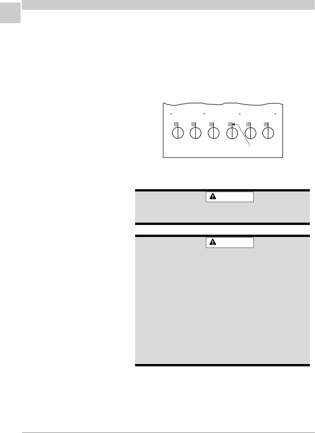
6-10
INSTALLATION Magic-Pak: HW/HWC
SRM-HW/HWC 8/99
Low NO Insert
x
FIGURE 6-4 NOx Insert Removal
Never use a flame to check for gas leaks. Explosion
causing injury or death may occur.
WARNING
Units for operation with propane must be converted with a kit supplied by
the manufacturer and require for operation an inlet pressure of 11" W.C.
minimum and 14" W.C. maximum. A regulator is also required on the
propane tank.
When converting a low NOx unit (designated by an L in the model num-
ber) to propane, the NOx inserts must be removed. After removing
the burners, remove the screw holding each insert and pull the insert from
the combustion chamber (see Figure 6-4). The screws must be rein-
stalled in the vest panel after the inserts are removed.
The furnace must be isolated from the gas supply
piping system by closing the individual manual shutoff
valve during any pressure testing of gas supply piping
system at test pressures equal to or less than 1/2 psig
or 14" W.C. If the piping system is to be tested at
pressures in excess of 1/2 psig, the furnace and its
individual shutoff valve must be disconnected from the
gas supply piping system. The gas valve supplied with
this furnace is rated at 1/2 psig. Any higher pressure
may rupture the pressure regulator diaphragm which
will cause over firing of the burners and improper
burner operation. This action may produce a high
concentration of carbon monoxide which can result in
asphyxiation.
WARNING
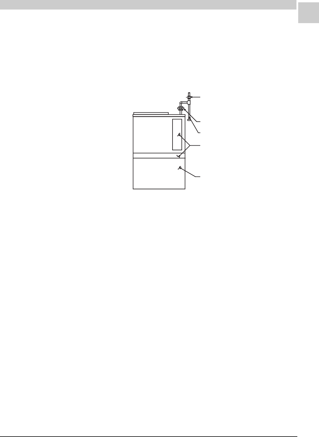
Service Reference Manual INSTALLATION
6-11
SRM-HW/HWC 8/99
Electrical Connections
All wiring must be done in accordance with the National Electrical
Code, ANSI/NFPA No. 70 (latest edition); Canadian Electrical
Code Part 1, CSA C22.1 (latest edition); or local codes, where they
prevail. Any alteration of internal wiring will void certification and
warranty.
The rating plate indicates the operating voltage, phase, ampacity, maxi-
mum fuse size and minimum voltage. Units must never be installed
where voltage exceeds 10% over the voltage indicated on the rating plate.
Units are factory wired for a 230 volt power supply. If power
supply is 208 volts, it will be necessary to change a wire connec-
tion on unit transformer from 240 volt terminal to 208 volt termi-
nal as shown on the wiring diagram.
Failure of the compressor as a result of operation on improper
voltage voids the compressor replacement warranty.
A separate electric line with wire having a temperature rating of 60°C
should be run directly from the main supply panel to the leads in the unit.
Refer to the rating plate located on the unit for proper fuse or breaker size.
Make sure the unit is electrically grounded in accordance with local codes
or, in the absence of local codes, with the National Electrical Code, ANSI/
NFPA No. 70 (latest edition) for installations in the U.S. or the Canadian
Electrical Code Part 1, CSA C22.1 (latest edition) for installations in
Canada.
A manual shutoff valve must be located outside the unit. The use of a
union located upstream of the controls is recommended, between the
controls and the manual shutoff valve. This will facilitate removal of
controls and manifold. See Figure 6-5 for recommended placement of the
union.
Provide a drip leg in the supply piping located exterior to the unit. Piping
must be tight and non-hardening. Pipe compound resistant to propane
must be used.
FIGURE 6-5 Gas Supply Piping
Manual Shutoff Valve w/ 1/8" NPT
plugged tapping, accessible for
test gauge connection (f supplied)ield-
Ground Joint Union (field-supplied)
Drip Leg (field-supplied)
Access Panels to
Controls and Burners
Access Panel To Filter
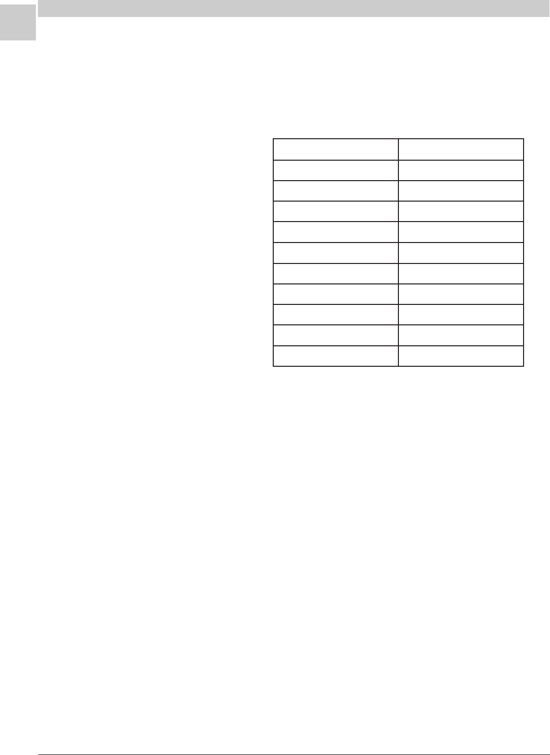
6-12
INSTALLATION Magic-Pak: HW/HWC
SRM-HW/HWC 8/99
TABLE 6-3 Minimum Circuit Ampacity
See Table 6-3 and the Specifications section beginning on page 1-1 for
correct wire ampacity for the cooling chassis required, and size the wire
accordingly.
For HW (heating only units): When sizing wire, keep in mind that
an air conditioning chassis may be added in the future.
Thermostat
Install the thermostat according to the directions furnished with it. The
thermostat must be located on an inside wall where it will not be affected
by drafts, sunlight or any other heat producing appliances. Connect the
thermostat wires to the low voltage leads on top of the unit following the
wiring diagram attached to the unit. The heat anticipator setting is 0.50
Amp.
Supply and Return Ducts
Provide ducts sized sufficiently to handle the larger of the air volumes for
heating or cooling provided by the unit.
Connect the supply duct to the top of the unit using canvas connections
or other flexible connections to prevent noise transmission into the duct
system.
The supply duct should have a removable access panel. The
opening should be accessible when the furnace is installed and
should be large enough and located such that the heat exchanger
can be inspected for leaks. The cover must be attached in such a
manner as to prevent air leaks.
To connect the return duct to the system, use a straight piece of duct 22"
wide by 6" deep. Insert the duct into the return opening in the bottom of
the unit and flange the duct over the existing flanges around the opening
ledoMsissahC.glCyticapmAtiucriC.niM
A8161
A4242
A0372
1813.31
14212
1036.32
321,2213.8
381,281llorcS4.51/yratoR6.31
342,2426.81
303,2034.22

Service Reference Manual INSTALLATION
6-13
SRM-HW/HWC 8/99
inside the unit. Make sure that all sides of the duct are flanged over to
permit removal of the cooling chassis if required. Use a flexible connec-
tion to attach the remainder of the return duct. The return duct should be
sealed to the unit casing and terminate outside the space containing the
furnace.
Air Filter
All indoor return air must be filtered. A permanent-type filter is furnished
with the unit, located directly behind the access panel. Removing the
panel permits access to the filter.
If an installation is made in which it is more desirable to mount the filter
exterior to the unit, in the return duct work or elsewhere, the permanent
filter can be used or replaced with a disposable filter. If a disposable filter
is used, refer to Table 6-4 when sizing the disposable filter.
TABLE 6-4 Minimum Required Surface Area for Disposable
Filters
Adjustments - Heating Section
Temperature Rise
At the time of installation, the temperature rise must be adjusted to be
within the range specified on the unit rating plate.
Pressure Regulator
The gas input must not exceed the figures shown on the rating plate. The
unit is equipped for rated inputs with manifold pressures of: 3.5" W.C. for
natural gas and 10.0" W.C. for propane.
The manifold pressure can be measured by removing the pipe plug in the
automatic gas valve. Connect a water manometer and measure the
pressure.
Only small variations in gas input may be made by adjusting the regulator.
In no case should the final manifold pressure vary more than 0.3"
W.C. for natural gas or 0.7" W.C. for propane.
rebmuNledoM)muminim(aerAretliFeziSretliFdeilppuS
321,221CWHsehcnierauqs003"05.x"5.52x"5.61
381,281CWHsehcnierauqs084"05.x"5.52x"5.61
342,242CWHsehcnierauqs084"05.x"5.52x"5.61
303,203CWHsehcnierauqs084"05.x"5.52x"5.61
WH62sehcnierauqs003"05.x"5.52x"5.61
WH83sehcnierauqs003"05.x"5.52x"5.61
WH15sehcnierauqs084"05.x"5.52x"5.61
WH46sehcnierauqs084"05.x"5.52x"5.61

6-14
INSTALLATION Magic-Pak: HW/HWC
SRM-HW/HWC 8/99
Adjustments - Cooling Section (HWC models)
No adjustments are required or should be attempted regarding any of the
components of the cooling chassis. The chassis should be checked to
see that none of the wiring is loose or missing.
Blower
The unit contains a direct-drive, multispeed blower. The proper speeds
have been preset at the factory for heating and cooling. Refer to the
wiring diagram for recommended heating/cooling speeds for specific
models. Direct-drive blower motors are permanently lubricated and do
not require oiling.
Limit Control
A fixed-temperature limit control is provided which will shut off the gas to
the main burners if the unit is overheated for any reason. The control
must not be adjusted or relocated.
High Altitude Adjustments (U.S. Installa-
tions)
Ratings shown on the rating plate are for elevations up to 2000 feet. For
elevations above 2000 feet, ratings should be reduced at a rate of 4% for
each 1000 feet above sea level. Refer to the National Fuel Gas Code
Z223.1 (latest edition) for further explanation.
High Altitude Adjustments (Canadian Instal-
lations)
High altitude conversions may be made by the manufacturer’s authorized
representative, in accordance with the requirement of the manufacturer,
provincial or territorial authorities having jurisdiction, and in accordance
with the requirements of CAN/CGA B149.1 or B149.2 Installation Code.
A high altitude conversion kit, available from the manufacturer and
approved for this purpose, must be used (see the Accessories section
beginning on page 7-15).
To adjust the regulator, turn the adjusting screw on the regulator clock-
wise to increase pressure and input or counterclockwise to decrease
pressure and input.
For natural gas installations, check the burner rate by observing the gas
meter (making sure that all other gas appliances are turned off). The test
hand on the meter should be timed for at least one revolution. Note the
number of seconds for one revolution.
BTU/HR
INPUT
Cubic Feet Per Revolution
# Seconds Per Revolution
Heating
Value
XX
=3600

Service Reference Manual INSTALLATION
6-15
SRM-HW/HWC 8/99
Installation and Operation in Extremely Cold
Weather Areas
In areas where extremely cold (below – 20°F) outdoor temperatures can
be expected, some additional installation and operating precautions
should be taken. The following precautions are taken to prevent possible
vent system ice blockage that could result in safety shutdown of the
burners:
1. Adjust to the highest achievable temperature rise within the rise and
static pressure ranges specified on the rating plate. Depending on
specific model, it may be possible to change to a lower heating blower
speed tap to get a higher temperature rise. This also increases
comfort.
2. Make sure there are no leaks of outside air into the return air system.
3. Keep the outside louver grille as free as possible of any ice that may
form and obstruct the flue outlet.

Service Reference Manual ACCESSORIES
7-1
SRM-HW/HWC 8/99
Section 7 - Accessories
HW/HWC Accessory Kit Index .............. 7-2
CA-239 Wall Sleeve Kit ................................... 7-3
A242-1 Wall Sleeve Adaptor Kit ...................... 7-7
ALVR42 Architectural Louver Facade ............. 7-10
34961A001 Vibration Isolator ...................... 7-12
ALPKT389-2 L.P. Gas Conversion Kit ............. 7-14
AHALT390-1 High Altitude Kit ....................... 7-15
ATIMR466-1 Nuisance Blower Repair Kit........ 7-17
ADAPT420-2 Chassis Conversion Kit .............. 7-18
Fenwal Triton Ignition Control Kit .................. 7-19
TL109 Burner Tray Kits ................................ 7-20
AMUFFKT494-1 Tecumseh “AW” Model
Compressor Sound Reduction Kit ................... 7-21

7-2
ACCESSORIES Magic-Pak: HW/HWC
SRM-HW/HWC 8/99
Accessories
There are a number of accessories available to increase the performance
or versatility of the Armstrong Magic-Pak HW/HWC units. This section
provides a general description of each.
Note: Complete instructions are packaged with each kit or its
components and accessories. These instructions should
be read carefully prior to installation. The instructions are
intended as a general guide only, for use by qualified
personnel, and do not supersede any national or local
codes in any way.
TABLE 7-1 HW/HWC Accessory Kit Index
REBMUNTRAPNOITPIRCSEDSLEDOMTINU
932-AC*tiKeveelSllaWnwoDdekconKsledoMCWH/WHllA
1-242AtiKrotpadAeveelSllaWsledoMCWH/WHllA
24RVLA*edacaFrevuoLmunimulAdedurtxElarutcetihcrA sledoMCWH/WHllA
100A16943tiKtemmorGnIgnirpS/rotalosInoitarbiVrosserpmoC sledoMCWH/WHllA
2-983TKPLA**tiKnoisrevnoCsaG.P.LsledoMCWH/WH46,15,83,62
1-093TLAHA**tiKnoisrevnoCedutitlAhgiH sledoMCWH/WH46,15,83,62
1-664RMITAtiKriapeRnoitarepOrewolBecnasiuN sledoM2seireSCWH/WHllA
2-024TPADAtiKnoisrevnoCsissahCsledoMCWH/WHllA
100-01134tiKnoisrevnoClortnoCnoitingI sledoM2seireSCWH/WHllA
A901LTtiKylbmessAyarTrenruBCWH/WH62
B901LTtiKylbmessAyarTrenruBCWH/WH83
C901LTtiKylbmessAyarTrenruBCWH/WH15
D901LTtiKylbmessAyarTrenruBCWH/WH46
1-494TKFFUMA tiKnoitcudeRdnuoSrosserpmoCledoM'WA'hesmuceT 281CWH
* Does not apply to 121, 181, 241 and 301 (48" tall series units use sleeve CA241).
** Does not apply to 12, 18, 24 and 30 or 121, 181, 241 and 301 units.

Service Reference Manual ACCESSORIES
7-3
SRM-HW/HWC 8/99
CA-239 Wall Sleeve Kit
The CA-239 wall sleeve kit is designed to facilitate the installation of
Magic-Pak units by providing an accurate opening to properly accept a
Magic-Pak unit. During the construction of a building, the wall sleeve
allows for the unit to remain off-site until the construction is completed.
The wall sleeve is comprised of four assemblies (top, bottom and left and
right sides) which assemble easily to form a correctly sized rectangular
box to receive a Magic-Pak unit.
When installed and securely fastened to the supporting wall, the wall
sleeve provides easy access to the finish wall for weather sealing.
The wall sleeve must always be fastened to the supporting wall
and never to the finished wall.
Inspection of Shipment
Upon receipt of equipment, carefully inspect it for possible shipping
damage. If damage is found, it should be noted on the carrier’s freight bill.
Damage claims should be filed with the carrier immediately. Claims of
shortages should be filed with the seller within five days.
Wall Sleeve Assembly
To assemble the wall sleeve, refer to the following directions and Figure 7-
1 on page 7-4.
1. Slide top panel over side panels until retaining clips are engaged in
slotted openings.
2. Place side and top assembly down with the front flange against floor
and slide bottom panel into side panel slip strips until tabs on bottom
panels are locked in place.
3. Attach squaring braces to top and side panels using existing holes.
(Do not remove braces until wall sleeve is secured to building.)
4. Attach the support angles to top and side panels using the #8 x 3/8"
screws provided. Two sets of holes are provided in the panels for
attaching the support angles. The row of holes nearest the front of
sleeve will locate the support angles for 1" spacing and the second
set of holes will locate the angles for 3-3/4" spacing.
5. Wall sleeve must be square in opening before securing sleeve
to building. This is required to assure Magic-Pak unit will slide into
the sleeve.
6. Caulk all seams where bottom panel joins to side panels including the
front corners of bottom panel and the top of side panel slip joints.
Caulk sealing is best accomplished after the wall sleeve is assembled
but before it is placed in the wall opening.
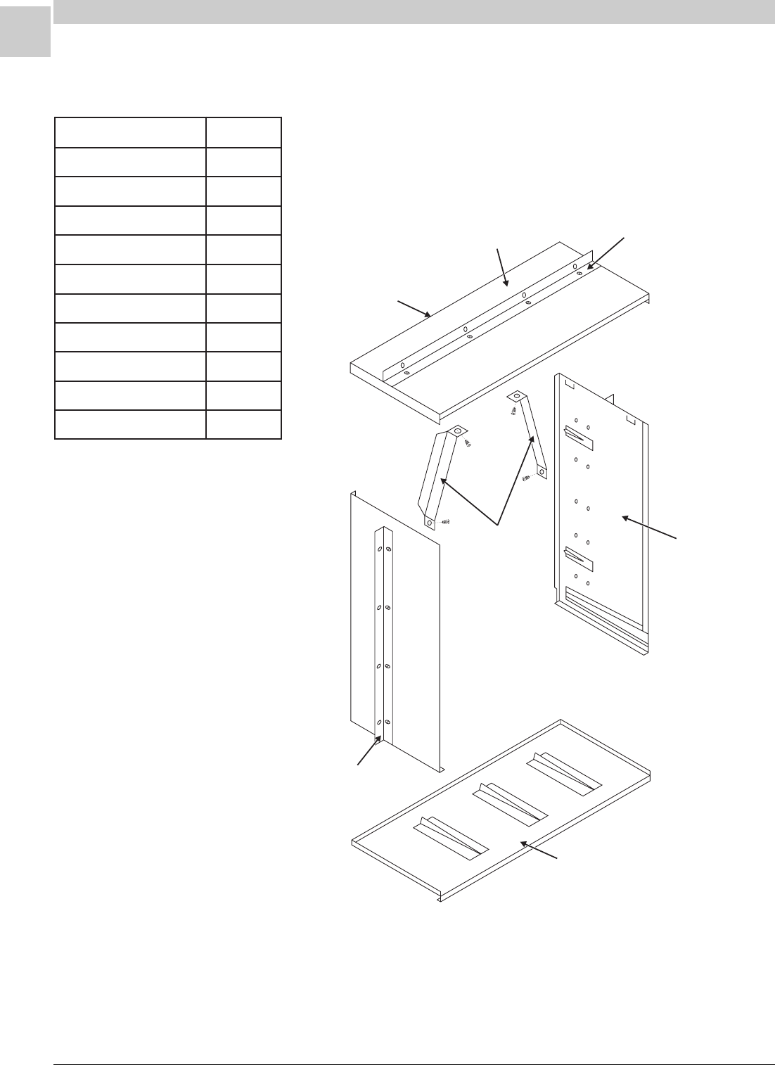
7-4
ACCESSORIES Magic-Pak: HW/HWC
SRM-HW/HWC 8/99
Top Panel
Front of
Sleeve
Support Angle - 8 Holes
Squaring
Braces
Left Side
Panel
Bottom Panel
Support Angle - 2 Sides
FIGURE 7-1 CA-239 Wall Sleeve Kit Assembly
TABLE 7-2 CA-239 Parts List
Assembled Wall Sleeve Dimensions: 45" high x 29" wide x 12.5" deep
noitpircseDytitnauQ
lenaPpoT1
lenaPmottoB1
lenaPediSthgiR1
lenaPediStfeL1
ecarBgnirauqS2
wercS"4/3x"4/15
wercS"8/3x8#42
rehsaWtalF"4/15
elgnAtroppuSediS2
elgnAtroppuSpoT1

Service Reference Manual ACCESSORIES
7-5
SRM-HW/HWC 8/99
Wall Sleeve Installation
The wall sleeve can be installed from either the inside or the outside of
the building. In any case, proper considerations must be made for final
weather sealing of the wall sleeve and the Magic-Pak unit.
Whether installing from the inside or outside of a building, the wall sleeve
may be secured to the supporting wall through the top and side support
angles or directly through the wall sleeve side panels. When securing the
wall sleeve directly through the side panels, the top and side angle
supports are often used as “stops” to assure proper alignment before final
securing of the wall sleeve is accomplished.
The top and side support angles can be adjusted to allow the unit to
protrude through the outside of the supporting wall by 1" or 3-3/4" inches.
This will also change the depth that the unit protrudes through the inside
wall. This adjustment is designed to allow for final sealing of the wall
sleeve to various finish types.
The top and side support angles can be removed altogether and the wall
sleeve secured directly through the side panels, provided that the installer
performs a proper alignment of the wall sleeve.
The further the wall sleeve is extended past the
finished wall the more difficult it becomes to accom-
plish final sealing from the inside of the building.
Adequate safety precautions must be considered to
protect personnel.
WARNING
Whether installing from the inside or the outside of the building, the wall
sleeve should extend at least 3/8" - 1" beyond the finished wall to allow for
proper weather sealing. When installing during wall construction, consid-
eration must be made to allow for final weather sealing to the type of
finish wall that will be constructed later.
Recessed Wall Sleeve Installation
In some applications, the thickness of the wall or architectural design will
dictate that the wall sleeve be recessed in the finished wall. This can be
done, but it is not recommended if the wall opening is required to be the
same size as the wall sleeve opening.
Recessed installation can be done if the wall opening is 2" larger verti-
cally than the wall sleeve. The wall sleeve may then be placed on a sill 2"
higher than the bottom of the finished wall opening.
The sill must be recessed 3/8" - 1" inside of the outer edge of the wall
sleeve. This permits weather sealing of the bottom edge without plugging
the drain holes in the bottom of the wall sleeve.
The top of the finished wall opening should extend above the top of the
wall sleeve by a dimension equal to or greater than the dimension that the
wall sleeve is recessed.

7-6
ACCESSORIES Magic-Pak: HW/HWC
SRM-HW/HWC 8/99
Magic-Pak Installation
Before installing the Magic-Pak unit in the wall sleeve, it is important to
consider the possibility of sound and vibration transmission through the
wall. It is recommended that vibration isolation pads be installed evenly
spaced across the outer edge of the bottom panel of the wall sleeve. The
vibration isolator pads should be approximately 4" x 4" x 7/8" and con-
structed of one piece of cork rubber with pieces of neoprene rubber
adhered to the top and bottom.
Once the wall sleeve is properly secured to the supporting wall and the
vibration isolators are in place, the Magic-Pak unit can be slid into the wall
sleeve. The unit must be slid completely forward so that the outer edges
of the unit touch the inside flanges of the wall sleeve. The unit can then
be secured to the wall sleeve by bolting the top flange of the unit to the
top turned-down flange of the wall sleeve with 1/4" x 3/4" bolts and
washers.
Note: In applications where vibration isolation is of particular importance,
rubber grommets (Armstrong P/N 9015A) can be inserted between
the top flanges.
The wall sleeve alone is not adequate support for the full weight of the
Magic-Pak unit. Additional, field-fabricated support must be provided
between the rear flange of the return opening and the wall sleeve.
The use of vibrator isolator pads is required between the unit and the
support and between the floor and the support.
Please refer to installation instructions and application manual for details
on field-fabricated additional supports.
Weather Sealing
After assembling the wall sleeve, it is recommended that all panel con-
nections and joints be sealed with caulk to prevent water and wind
infiltration into the building.
Once the Magic-Pak is installed and secured to the wall sleeve, it is
important to seal any gaps between the wall sleeve and the unit with
caulk. This includes both sides, top and bottom. Sealing these gaps will
prevent water and wind from leaking into the building between the unit
and wall sleeve.
The outside of the wall sleeve must also be sealed with caulk on all four
sides whether it is installed recessed or protruding.

Service Reference Manual ACCESSORIES
7-7
SRM-HW/HWC 8/99
A242-1 Wall Sleeve Adaptor Kit
The A242-1 wall sleeve adaptor kit is designed to allow for the installation
of current 43" tall HW/HWC units into 48" tall wall sleeves (CA241 wall
sleeve kits). The CA241 wall sleeve kits were designed for use with HW/
HWC121, 181, 241 and 301 units manufactured during the late 1980’s.
The HW/HWC series 1 units were approximately 48" tall.
If replacement of the wall sleeve is not feasible, use of the A-242-1
adaptor kit creates an insulated block-off panel at the top portion of the
CA241 wall sleeve.
The adaptor kit also allows for easy mounting of the HW/HWC unit to the
taller sleeve.
Whenever it is necessary to convert a CA241 wall sleeve to current unit
dimensions, use of the A242-1 adaptor kit is required.
Inspection of Shipment
Upon receipt of equipment, carefully inspect it for possible shipping
damage. If damage is found, it should be noted on the carrier’s freight bill.
Damage claims should be filed with the carrier immediately. Claims of
shortages should be filed with the seller within five days.
Wall Sleeve Adaptor Kit Assembly
Once assembled, the A242-1 adaptor kit will form a rectangular box
approximately 4-7/8" tall with approximately 7/8" overlapping the front and
side of the top panel of the HW/HWC unit (see Figure 7-2 on page 7-9).
To assemble the adaptor kit:
1. Set top flanges of side and front panels on the floor or ground so that
they are resting flat. The screw holes through the side flanges of front
panel should align with the pilot holes in side panel.
2. Fasten two #8 x 1/2" screws in each side.
3. Place rear panel against the rear flanges of the side panels. The
screw holes of the rear panel should align with the pilot holes in the
side panel rear flanges.
4. The top and bottom flanges of the rear panel should be facing the
front panel. The five 1/4" pilot holes should be positioned towards the
bottom of the kit and the five oval screw holes should be positioned
towards the top of the kit.
5. Fasten two #8 x 1/2" screws at each end of the rear panel.

7-8
ACCESSORIES Magic-Pak: HW/HWC
SRM-HW/HWC 8/99
Attachment to HW/HWC
After assembling the kit, it is ready to be attached to the top of the HW/
HWC unit. To attach the kit to the HW/HWC unit:
1. Remove the two front screws (each side) that fasten the top panel
side flanges to the side panels on each side of the HW/HWC unit.
2. Place the adaptor kit on top of the HW/HWC unit. The five pilot holes
positioned towards the bottom of the kit’s rear panel should align with
the five oval screw holes in the HW/HWC mounting bracket (see
Figure 7-2).
3. Fasten the five 1/4" x 3/4" screws and washers through the unit
mounting bracket to the kit pilot holes.
4. Align the kit side panel oval screw holes to the screw holes in the side
of the HW/HWC unit.
5. Re-fasten the screws that were removed in step 1.
Installing the HW/HWC Unit
After the adaptor kit is fastened to the HW/HWC unit, the unit is ready to
be slid into the wall sleeve.
The top flange of the adaptor kit is designed to overlap the top of the wall
sleeve. The five 1/4" x 3/4" mounting screws included with the wall sleeve
kit can be fastened through the top flange of the kit into the turned-down
flange of the wall sleeve.
The HW/HWC unit must be slid all the way forward so that the outer
edges of the adaptor kit and HW/HWC unit are touching the outer flanges
of the wall sleeve.
The HW/HWC unit and wall sleeve must be weather sealed according to
the wall sleeve kit instructions, unit installation instructions or unit applica-
tion manual.
For further information on installing HW/HWC units, refer to the Installa-
tion section beginning on page 6-1.
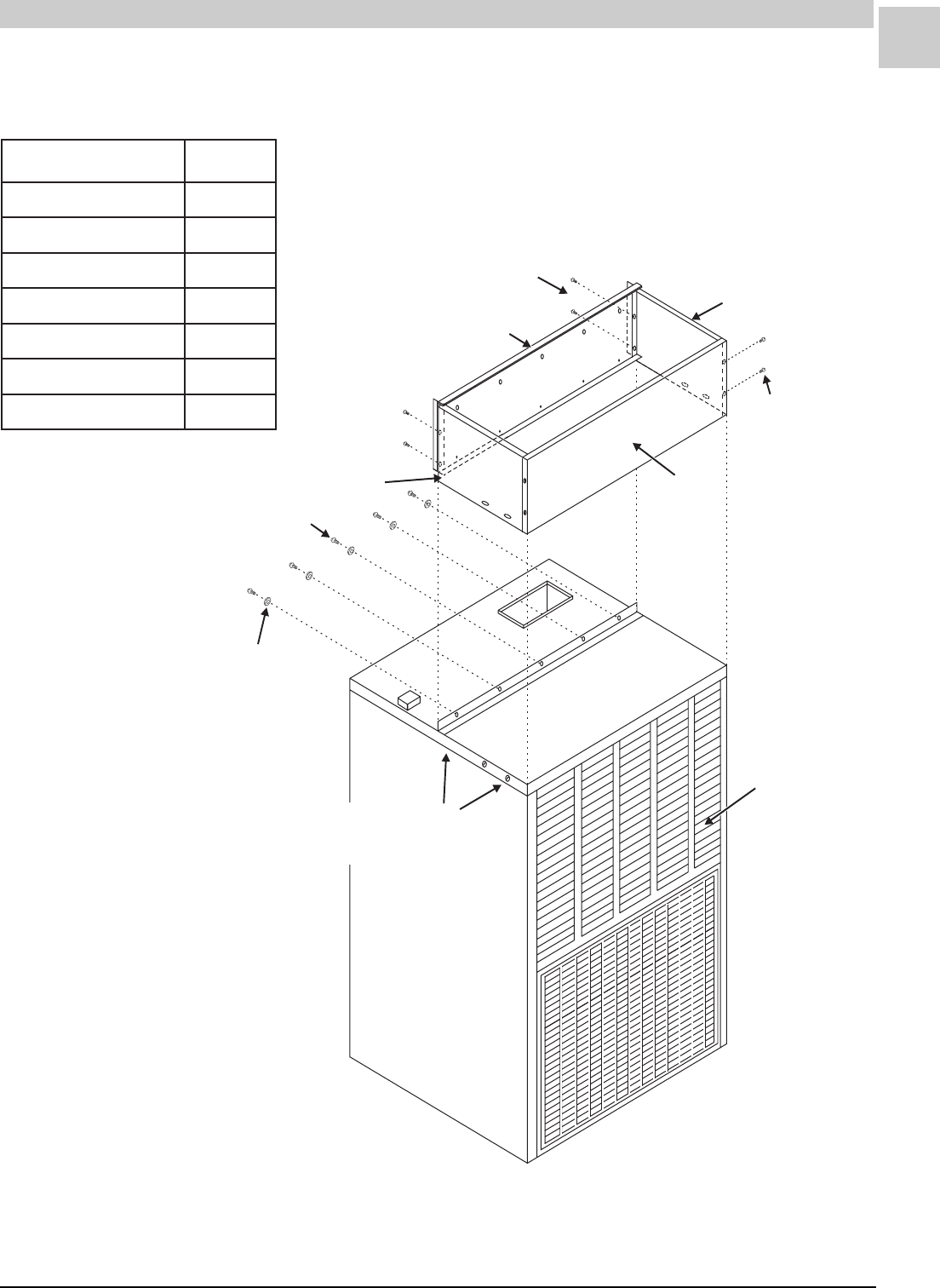
Service Reference Manual ACCESSORIES
7-9
SRM-HW/HWC 8/99
(2) #8 x ½" Screws
in each rear corner
(2) #8 x ½" Screws
in each side
Right Side
Front
1/4" x ¾" Screw
¼" Flat Washer
HW/HWC Unit
Rear
Left Side
Screws that are removed
and reinserted to attach adapter kit
to HW/HWC unit (both sides)
FIGURE 7-2 A242-1 Wall Sleeve Adaptor Kit Assembly
TABLE 7-3 A242-1 Parts List
traPytitnauQ
lenaPtnorF1
lenaPraeR1
lenaPediSthgiR1
lenaPediStfeL1
wercS"2/1x8#8
wercS"4/3x"4/15
rehsaWtalF"4/15

7-10
ACCESSORIES Magic-Pak: HW/HWC
SRM-HW/HWC 8/99
ALVR42 Architectural Aluminum Louver
Facade
In many applications, architects and installers will choose to use facades
over the front of Magic-Pak units. Often this is done to improve the
appearance of a building. Properly constructed louver facades may also
provide some degree of weather protection and sound deflection.
Louver facades can be designed by engineers and architects and inte-
grated into the building construction by contractors in the field. However
research and testing has shown that many designs may actually diminish
the performance of the Magic-Pak units and in some cases even damage
them.
For these reasons, Armstrong approved the ALVR42 architectural alumi-
num louver facade kit. The instructions provided with the kit should serve
as a general guide for installation of the kit. For guidelines on designing
louver facades, refer to the Magic-Pak Application Manual (Armstrong
P/N MPA-100).
The ALVR42 is designed to be integrated into the construction of the
finish wall or secured directly to the finish wall. Therefore, actual installa-
tion of the louvers will vary depending on the type of finish wall it is
applied to.
The ALVR42 kit is available is many different colors to match finish walls.
Color matching services are also available. For more information con-
cerning color matching, please contact your supplier or Armstrong.
Assembly
The ALVR42 kit consists of two sections of louver fins. The top section is
composed of fins angled approximately 30° upward while the bottom
section consists of fins angled approximately 30° downward (see Figure
7-3). This design allows flue gases and condenser discharge air to be
circulated away from the condenser inlet and burner compartment fresh
air intake.
There is also a sealing gasket between the two louver sections to allow
for separation of inlet and discharge air when the louver is secured
directly to the front of the unit. When the louver is secured away from the
unit, a separation bracket sealed to the unit and then to the louver kit
must be field-fabricated and installed.
The ALVR42 louver is 45" tall to accommodate proper drainage of the unit
and wall sleeve and proper discharge of condenser air and flue gases.
Installation
The ALVR42 is designed to be fastened to the finish wall, support wall or
wall sleeve using field-supplied materials and techniques.
Whenever installing a louver facade of any type, special considerations
must be made for proper drainage and air circulation. The drain holes of
the wall sleeve and the unit must never be obstructed.
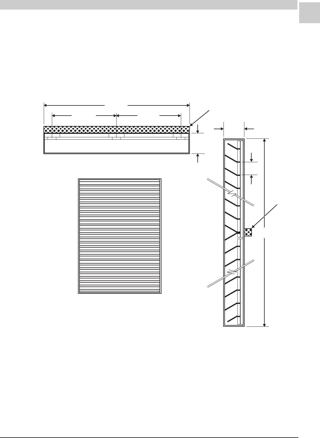
Service Reference Manual ACCESSORIES
7-11
SRM-HW/HWC 8/99
The louver will fit directly against the front of the unit. However, the lower
lip of the unit will protrude into the louver. The louver must be positioned
to accommodate the protruding lower lip.
The louver must be caulk sealed on all four sides and field-supplied
flashing should be installed across the bottom of the louver. This will
prevent water runoff directly onto the finish wall.
FIGURE 7-3 ALVR Architectural Aluminum Extended Louver
13.831" 13.831"
28.875"
1.225"
Ty p.
.500" x .375" x 28.875"
Polyether Gasket
1.225"
Ty p.
.775"
Ty p.
45.000"
Gasket

7-12
ACCESSORIES Magic-Pak: HW/HWC
SRM-HW/HWC 8/99
34961A001 Compressor Vibration Isolator
Kit
The 34961A001 spring/grommet kit is designed to isolate vibrations
common to most compressors away from the base of Magic-Pak units
and building walls.
Some types of wall construction will be especially susceptible to vibration
transmissions. In these instances, installers and building designers must
make special considerations for isolating vibration.
Designing and constructing walls and wall openings in a particular
manner to isolate vibration transmission is the recommended procedure
for dealing with these instances. However, if further vibration isolation is
necessary, the 34961A001 compressor vibration isolator kit should be
used.
For instructions and recommendations on designing and constructing
walls and wall openings, refer to the Magic-Pak Application Manual.
Installation
The Magic-Pak cooling chassis must be removed from the cabinet to
perform the following installation procedures. Refer to the Chassis
Removal section beginning on page 3-4 for instructions on proper chassis
removal.
To install the 34961A001 kit:
1. Remove the factory-installed compressor mounting leg bolts from the
base of the compressor.
2. Lift the compressor of the base of the chassis by inserting a large
screwdriver or pry bar under the belly of the compressor.
3. Support the compressor by sliding a 3/4" to 1-1/4" thick wooden block
or suitable material underneath the compressor belly.
The copper refrigerant tubing connected to the compressor will
have some free movement. However, be careful not to kink or
damage the tubing. Loss of refrigerant or lack of proper unit
performance may result.
4. Remove the factory-installed rubber grommets from the compressor
mounting legs.
5. Install the top rubber spacer in the compressor mounting legs.
6. Insert the bottom rubber spacer into the bottom of the spring and
slide the spring between the upper spacer and chassis base.
7. Insert the metal sleeve through the top of the upper spacer, spring
and lower spacer.
8. Re-install the bolts removed in step 1.

Service Reference Manual ACCESSORIES
7-13
SRM-HW/HWC 8/99
Use of spray lubricant or liquid soap will aid in the installation of rubber
parts.
Compressor belly is rounded and can be “rocked” on the belly support. It
is easiest to install one spring grommet at a time. Start with the most
difficult to access compressor mounting leg and work in a crisscross
pattern from back to front.
Compressor mounting bolts should be tightened down so that the metal
sleeve is secured fast to the chassis base and bolt head. Before securing
the final bolt, make sure that the wooden block or material supporting the
belly of the compressor has been removed.
TABLE 7-4 34961A001 Parts List
traPytitnauQ
recapSrebbuRreppU4
recapSrebbuRrewoL4
gnirpS4
eveelSlateM4
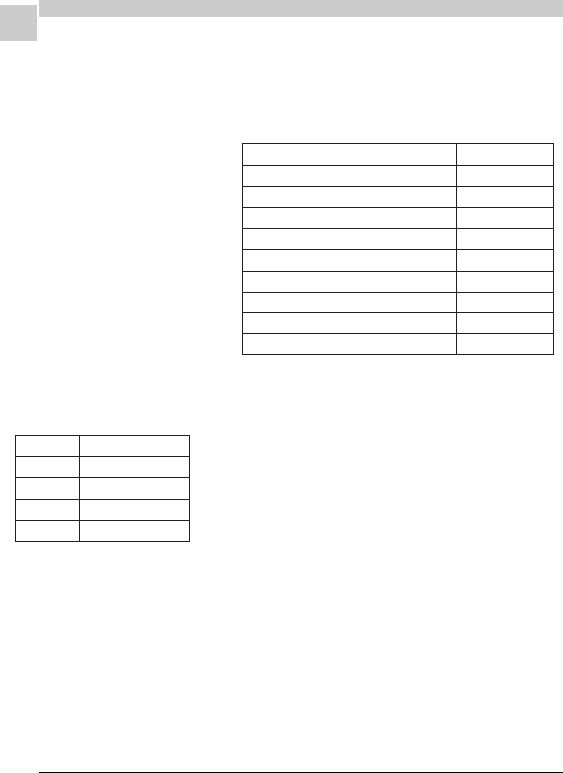
7-14
ACCESSORIES Magic-Pak: HW/HWC
SRM-HW/HWC 8/99
ALPKT389-2 L.P. Gas Conversion Kit
The ALPKT389-2 kit contains the following parts to convert the 26, 38, 51
and 64HW/HWC series gas furnace from natural gas to propane gas. For
altitudes from 2000 - 4500 feet, a high altitude kit as supplied by the
manufacturer must be used (see page 7-15).
Although the equipment is suitable for operation with propane gas (after
the conversion kit has been installed), certain precautions must be
observed because of the distinct burning characteristics of propane gas.
The following problems may be encountered:
1. Burning back at the orifices with a loud roar
2. Loud popping upon extinction of the burner
3. Flame rollout at the time of the ignition
These problems can be caused by:
1. Low gas pressure
2. Improper air adjustment
3. Incorrect burning rate
The furnace has a regulator in the gas valve. A regulator is also required
on the propane tank. Another regulator may be required at the house or
the unit.
The minimum permissible gas supply pressure to the furnace is 11" W.C.
for the purpose of input adjustment. The maximum permissible gas
pressure to the gas valve is 14" W.C.
TABLE 7-5 ALPKT389-2 Parts List
traPytitnauQ
etalPnoisrevnoC1
lebaLnoisrevnoCsaG1
lebaLtnemtsujdArettuhSriA1
snoitcurtsnInoitallatsnI1
evlaVsaGK52sregdoR-etihWroftiKretpadA1
secifirOrenruBniaM56#3
secifirOrenruBniaM46#4
secifirOrenruBniaM26#6
lebaLnoisrevnoCevlaVsaG1
ledoMeziSecifirOenaporP
CWH/WH6256#
CWH/WH8346#
CWH/WH1526#
CWH/WH4626#
TABLE 7-6 ALPKT389-2 Orifices
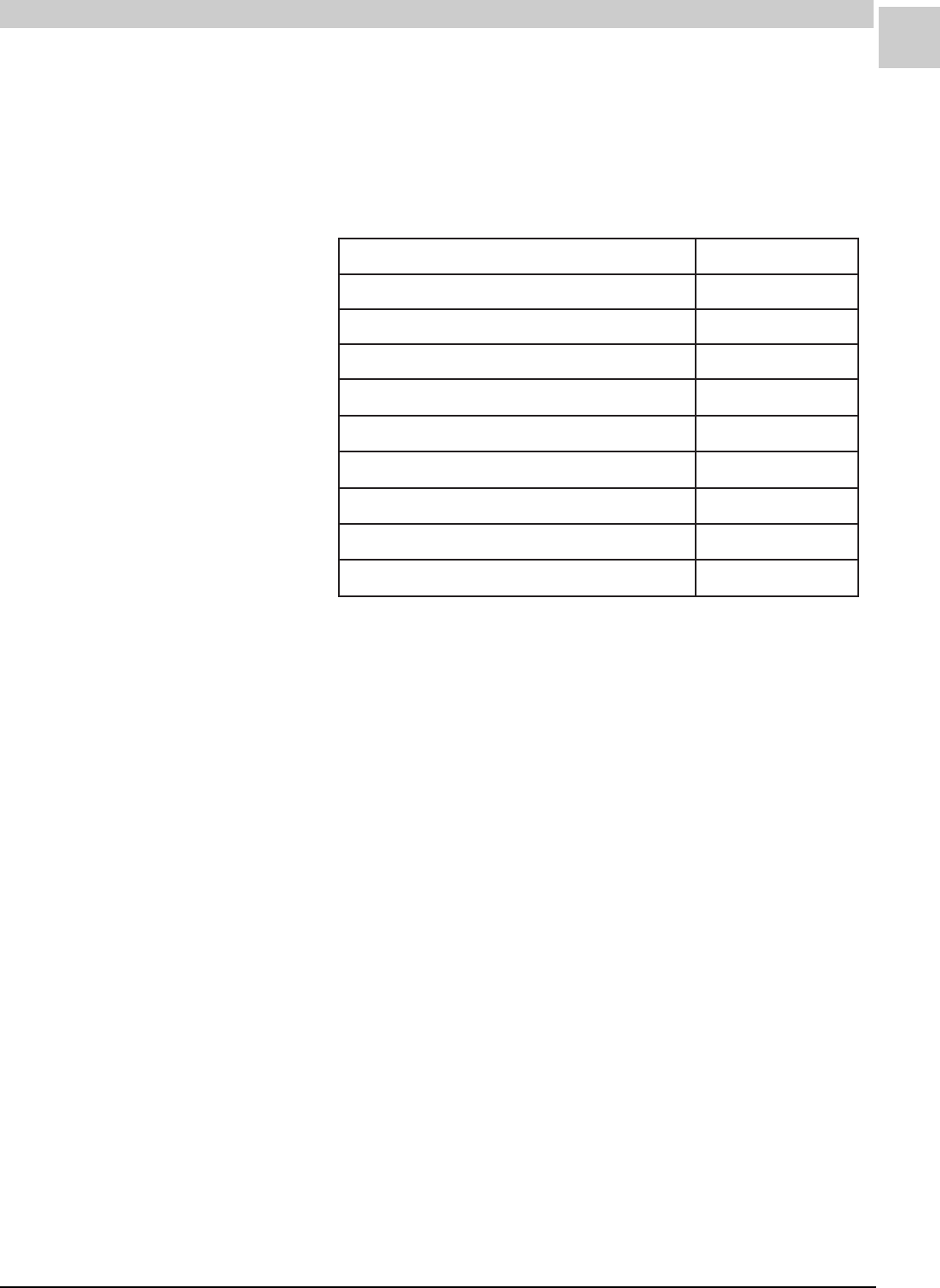
Service Reference Manual ACCESSORIES
7-15
SRM-HW/HWC 8/99
AHALT390-1 High Altitude Kit
The AHALT390-1 kit contains the following parts to convert the 26, 38, 51
and 64HW/HWC series units to high altitude for natural or propane gas. If
the field conversion is for high altitude propane gas, be sure to install the
appropriate gas valve conversion kit (see page 7-14).
Regulator - Natural Gas
The minimum permissible gas supply pressure is 5.0" W.C. for purpose of
input adjustment. Gas input must never exceed the input capacity shown
on the rating plate. The furnace is equipped for rated inputs with manifold
pressure of 3.5" W.C. for natural gas. Only small variations in gas input
may be made by adjusting the regulator. In no case should the final
manifold pressure vary more than 0.3" W.C. from the specified pressure.
To check this pressure:
1. Turn off the gas valve.
2. Remove the plug on the valve marked “OUTLET PRESSURE”.
3. Install a water manometer.
Turn gas valve “ON”. If manifold pressure must be adjusted, remove cap
from pressure regulator and turn adjustment screw clockwise to increase
pressure, counterclockwise to reduce pressure. After checking pressure,
turn gas off, remove the manometer fitting and replace the pipe plug and
regulator cap. Put furnace in operation and leak check plug for leaks
using a soapy solution.
Check the furnace rate by observing the gas meter, when available,
making sure all other gas appliances are turned off. The test hand on the
meter should be timed for at least one revolution. Note the number of
seconds for one revolution.
TABLE 7-7 AHALT390-1 Parts List
traPytitnauQ
snoitcurtsnInoitallatsnI1
etalPnoisrevnoCedutitlAhgiH1
lebaLtnemtsujdArettuhSriA1
)saGlarutaN(55#secifirOrenruB3
)saGlarutaN(45#secifirOrenruB5
)saGlarutaN(35#secifirOrenruB6
)saGenaporP(56#secifirOrenruB3
)saGenaporP(46#secifirOrenruB4
)saGenaporP(36#secifirOrenruB6

7-16
ACCESSORIES Magic-Pak: HW/HWC
SRM-HW/HWC 8/99
x 3600 x
=Cubic Feet Per RevolutionBTU/HR
INPUT # Seconds Per Revolution Heating
Value
The heating value of your gas can be obtained from your local utility.
With proper manifold pressure achieved, cycle main burners on and off.
Ignition and extinction should be smooth and quiet. Burning back at the
orifice or flame popping back to the orifice can be corrected by adjusting
the air shutter to soften the flame.
Regulator - Propane
The furnace has a regulator in the gas valve. A regulator is also required
on the propane tank. Another regulator may be required at the house or
the unit.
The minimum permissible gas supply pressure to the furnace is 11" W.C.
for the purpose of input adjustment.
If at any time ignition is slow and the burner does not seem to be operat-
ing correctly, check manifold pressure. It should be between 10" to 10.5"
W.C.
The furnace is designed to obtain rated input at 10.0" W.C.
To check this pressure:
1. Turn off the gas valve.
2. Remove the plug on the valve.
3. Install a water manometer.
Turn gas valve “ON”. If manifold pressure must be adjusted, remove cap
from pressure regulator and turn adjustment screw clockwise to increase
pressure, counterclockwise to reduce pressure. After checking pressure,
turn gas off, remove the manometer fitting and replace the pipe plug and
regulator cap. Put furnace in operation and leak check plug for leaks
using a soapy solution.
With proper manifold pressure achieved, cycle main burners on and off.
Ignition and extinction should be smooth and quiet. Burning back at the
orifice or flame popping back to the orifice can be corrected by adjusting
the air shutter to soften the flame.
Model
Size
Normal
Input
Btuh
High
Altitude
Input
Btuh
High
Altitude
Output
Btuh
Orifice Size
Natural Propane
TABLE 7-8 AHALT390-1 Orifices
CWH/WH62000,62004,32000,815556
CWH/WH83000,83002,42000,724546
CWH/WH15000,15009,54000,634536
CWH/WH46000,46006,75000,543536
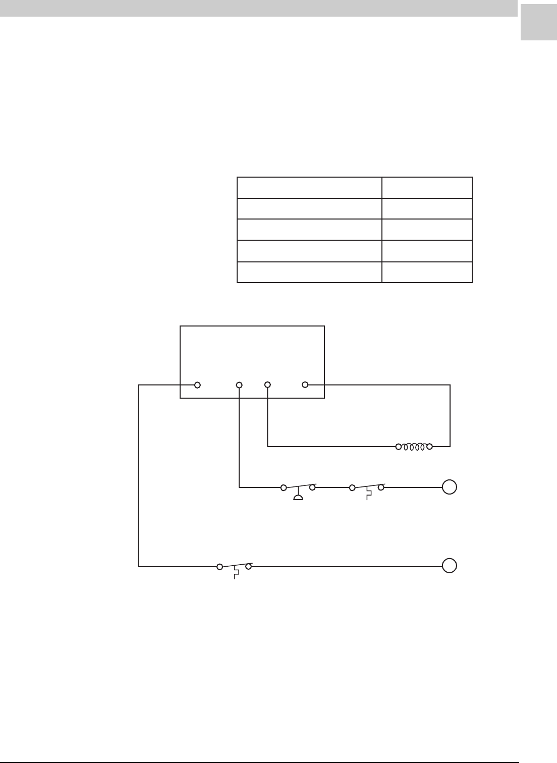
Service Reference Manual ACCESSORIES
7-17
SRM-HW/HWC 8/99
ATIMR466-1 Short Cycle Protector Kit
The ATIMR466-1 Short Cycle Protector Kit helps guard against compres-
sor failure due to repeated, short interval on/off cycles. It is also referred
to as the Nuisance Blower Operation Repair Kit.
The kit is designed to be used in conjunction with matching air conditioner
or heat pumps for comfort cooling/heating applications as shown in the
Armstrong specification information.
FIGURE 7-4 ATIMR466-1 Kit Wiring
TABLE 7-9 ATIMR466-1 Parts List
Time Delay
Relay
T’stat Common Load
Contactor
Coil
C
Y
Yellow
Blue
High Pressure
Cutout
(If Used)
Discharge
Thermostat
(If Used)
Discharge
Thermostat
(If Used)
Low Voltage Leads
to Contactor Coil
from Thermostat
traPytitnauQ
yaleRyaleDemiT1
renetsaF1
seriW3
snoitcurtsnInoitallatsnI1
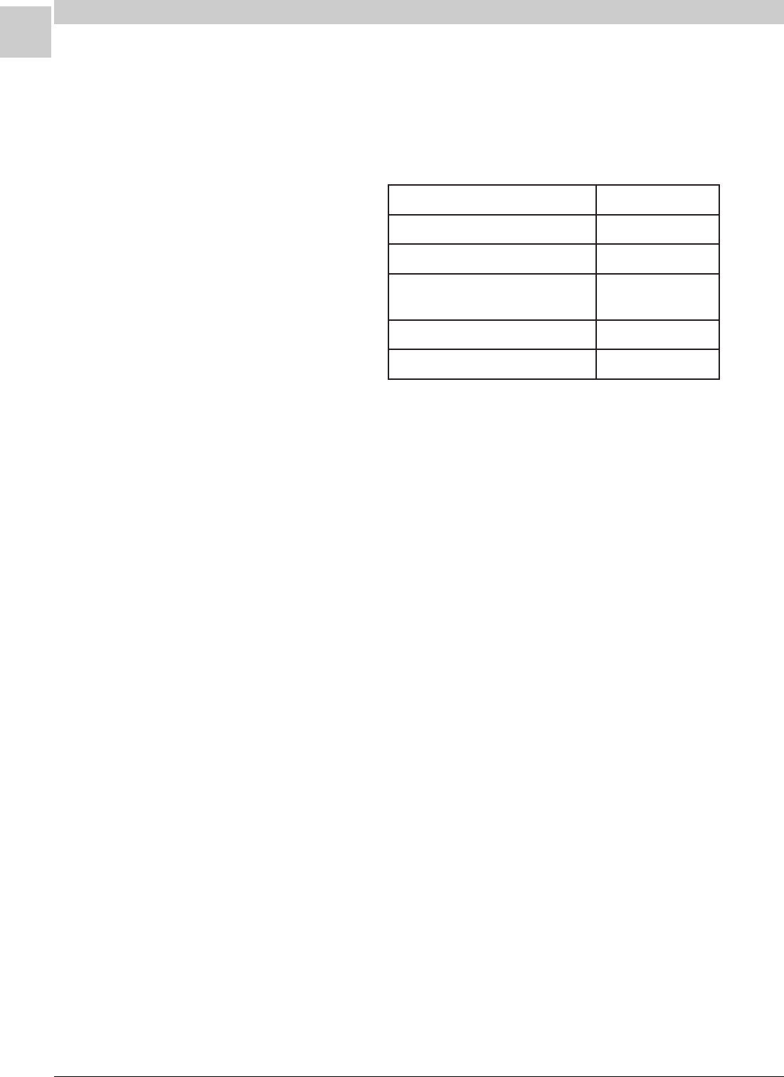
7-18
ACCESSORIES Magic-Pak: HW/HWC
SRM-HW/HWC 8/99
ADAPT420-2 Chassis Conversion Kit
The ADAPT420-2 kit was designed to retrofit an HWC122, 182, 242 or
302 chassis onto a cabinet originally equipped with an HWC12, 18, 24 or
30 chassis. This kit cannot be used to replace an HWC181, 241 or 301.
When replacing the old chassis, the new chassis must have the same
nominal cooling capacity. If the nominal cooing capacity of the new
chassis is larger than the original, both the appliance internal line voltage
wire and the field wiring must be checked for proper size. The fuse
and/or breaker size must also be checked.
TABLE 7-10 ADAPT420-2 Parts List
traPytitnauQ
snoitcurtsnInoitallatsnI1
lenaPrelliF1
lenaPraeRretneC
)troppuSlenaPsseccAretliF( 1
)sehcni21(epaTgnilaeSmaoF1
slebaLmargaiDgniriW2

Service Reference Manual ACCESSORIES
7-19
SRM-HW/HWC 8/99
Fenwal Triton Ignition Control Kit
This kit enables the Fenwal “Triton” local sense, one-hour retry, direct
spark ignition (DSI) control to be used as a service parts replacement for
earlier versions of Fenwal DSI controls used on HW/HWC models.
The operation and features of this ignition control differ from the other
types of DSI controls used. These features include:
• Longer trial for ignition (15 seconds nominal).
• One-hour retry feature (if main burner operation is not proved after
three trials for ignition, control goes into lockout for one hour, then
automatically initiates another ignition sequence; will repeat as long
as call for heat exists).
• Senses flame through spark electrode (local flame sense) instead of
through a separate flame sensor (remote flame sense).
• Diagnostic LED indicates certain ignition and venting system mal-
functions (refer to control label for specific diagnostic codes).
• Includes flame current (FC) test terminals.
TABLE 7-11 Triton Ignition Control Kit Parts List
traPytitnauQ
saGkrapStceriDseireSD1642"notirT"lawneF
lortnoCnoitingI 1
elbaCedortcelEegatloVhgiH1
eriWrepmuJegatloVwoL
)slanimreTlortnoCnoitingInodellatsni-erPeByaM( 1
lebaLgniriW1
snoitcurtsnInoitallatsnI1
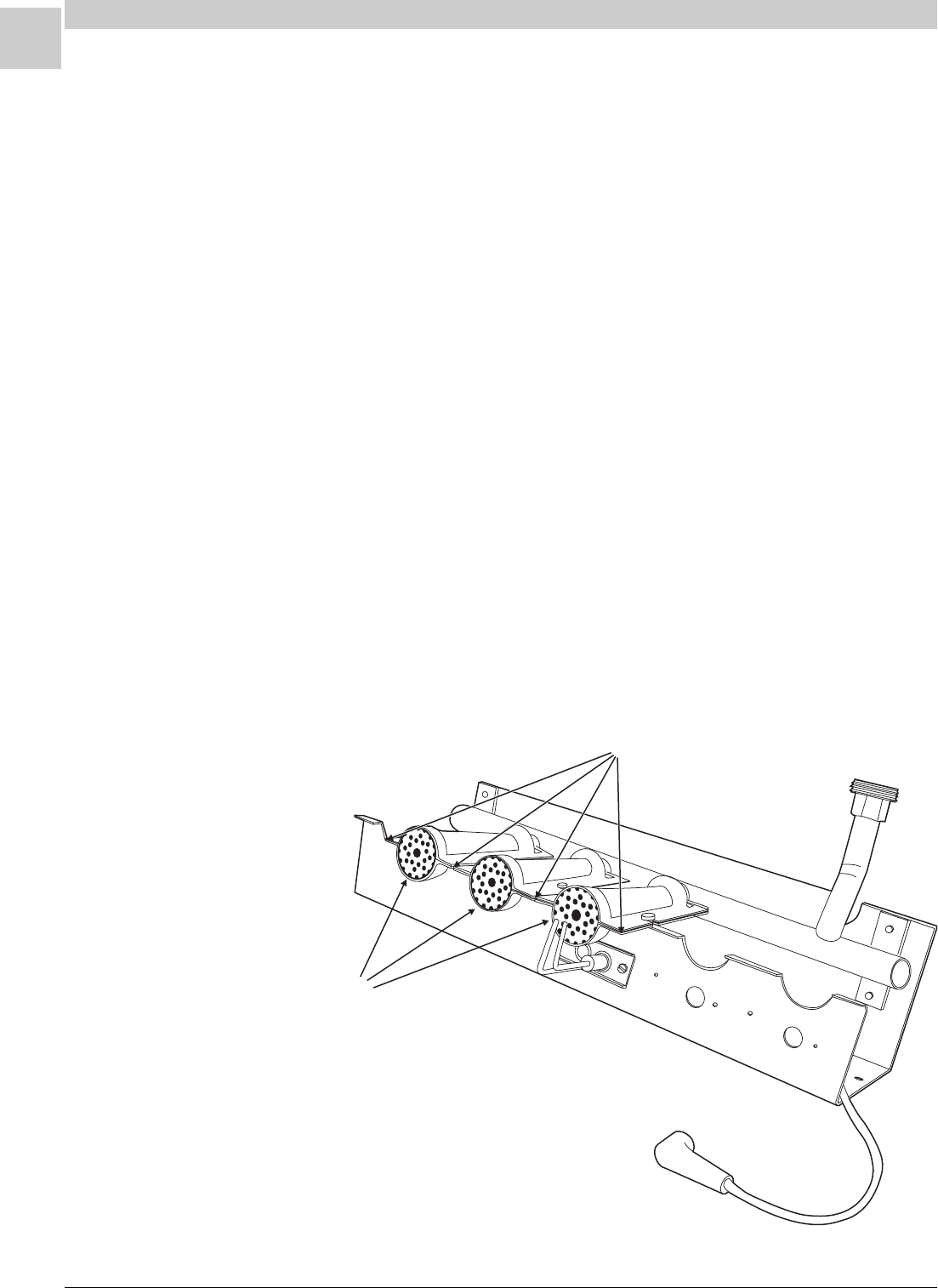
7-20
ACCESSORIES Magic-Pak: HW/HWC
SRM-HW/HWC 8/99
TL109 Burner Tray Kit
The TL109 Burner Tray Kit is designed for use in HW/HWC’s that were
originally equipped with single port inshot burners. Four kits are available,
one for each natural gas heating input rating as follows:
• 26,000 BTUH (3 main burners)
• 38,000 BTUH (4 main burners)
• 51,000 BTUH (5 main burners)
• 64,000 BTUH (6 main burners)
Each kit includes:
• An assembled burner tray including manifold, natural gas orifices and
3, 4, 5 or 6 main burners (depending on heating input rating
• A three-rod combination igniter/sensor
• Installation instructions
The burner tray assembly included in this kit can be used with either the
Fenwal remote sense ignition control (which uses a separate flame
sensor lead), or the more recent Fenwal local sense ignition control
(which does not use a separate flame sensor lead). When used with the
remote sense ignition control, the three-rod combination igniter/sensor in
the kit effectively makes this a “local sense” system.
FIGURE 7-5 TL109 Burner Tray
Burners
Burner Carryover Gap
.025 (+/ .002 )""
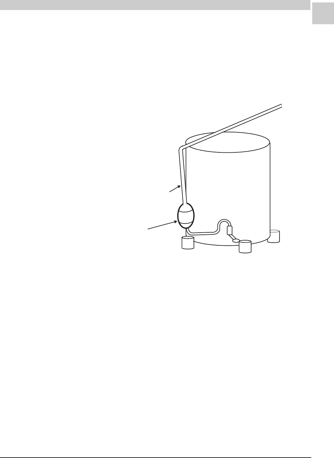
Service Reference Manual ACCESSORIES
7-21
SRM-HW/HWC 8/99
Discharge
Muffler
Discharge Line to
Condenser Coil
FIGURE 7-6 AMUFFKT494-1 Kit Discharge Muffler Installation
AMUFFKT494-1 Discharge Muffler Kit
In the event that during operation an unacceptable noise occurs, a muffler
kit (AMUFFKT494-1) may be installed in the discharge line*. The cham-
ber of the muffler acts as a sound-absorbing chamber reducing compres-
sor pulsation noises.
* AMUFFKT494-1 is designed to be used only with HWC182 units.

8-1
SRM-HW/HWC 8/99
Service Reference Manual PARTS LISTS
Section 8 - Parts Lists
HWC123, 183, 243, 303-1 .................. 8-2
HWC182, 242-11 ................................ 8-5
HWC122, 242-10 ................................ 8-7
HWC182-9 ........................................ 8-10
HWC242, 302-9 ................................ 8-12
HWC122, 182, 242, 302-8 ................ 8-14
HWC182-6/7 .................................... 8-17
HWC122, 282, 242, 302-5 ................ 8-19
HWC182, 302-4 ................................ 8-22
HWC122, 182, 242, 302-3 ................ 8-25
HWC182-2 ........................................ 8-28
HWC122, 182, 242, 302--1 ............... 8-30
HW-1 ................................................ 8-33
HWA-9 .............................................. 8-35
HWC123, 183, 243, 303S-1
(Low Ambient) .................................... 8-37
HWC123, 183, 243, 303H-1
(High Altitude) ................................... 8-40
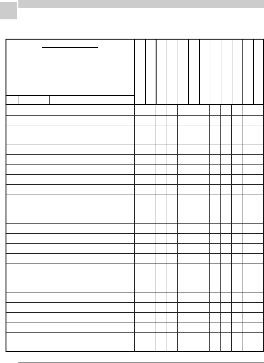
8-2
PARTS LISTS MAGIC-PAK: HW/HWC
SRM-HW/HWC 8/99
REC STOCKING PART
TO SELECT PART #
Last letter of the Model # is the Service Level.
64HWC303A-1A
First find Model #. ------------------------------------------------ >
64HWC303A-1(*)
Then match Service Level for desired part.---------------- >
SERVICE LEVEL = *
51HWC183A-1(*)
64HWC183A-1(*)
38HWC243A-1(*)
51HWC243A-1(*)
64HWC243A-1(*)
51HWC303A-1(*)
REF PART # PART DESCRIPTION
26HWC123A-1(*)
38HWC123A-1(*)
38HWC183A-1(*)
64HWC303A-1(*)
REVISED
4-26-99
HWC3-A-1
1100B07393REMROFSNART +A1111111111
7100-78944LLEWYENOHSAG-EVLAV +A1111111111
11100-47024DLOFINAMA1
11200-47024DLOFINAMA111
11300-47024DLOFINAMA111
11400-47024DLOFINAMA111
31300B03093SAGLARUTAN25#ECIFIROA666
31400B03093SAGLARUTAN35#ECIFIROA445455
31500B03093SAGLARUTAN45#ECIFIROA31
02100-29944EDORTCELE +A1111111111
12100-39944EDORTCELE-ERIW +A1111111111
42100-09944REWOLB/NOITINGI-LORTNOC +A1111111111
43100-84914RENRUBA3445645656
83900D99983REGNAHCXETAEH-YLBMESSAA1
83010D99983REGNAHCXETAEH-YLBMESSAA111
83110D99983REGNAHCXETAEH-YLBMESSAA111
83210D99983REGNAHCXETAEH-YLBMESSAA111
04100B14883SROTALUBRUTA3445645656
64100B77983REVOCEULF-TEKSAG +A1111111111
74100B87983DNE.LOCEULF-TEKSAG +A2222222222
25700B45104TIMIL-LORTNOC +A1111111111
55400B02573DERTUOLLOR-HCTIWS +A 111111111
55500B02573NEERGTUOLLOR-HCTIWS+A1
75010-91844DERERUSSERP-HCTIWS A1111111111
36100-44114TFARDDECUDNI-REWOLB +A1111111111
8-3
SRM-HW/HWC 8/99
Service Reference Manual PARTS LISTS
REC STOCKING PART
TO SELECT PART #
Last letter of the Model # is the Service Level.
64HWC303A-1A
First find Model #. ------------------------------------------------ >
64HWC303A-1(*)
Then match Service Level for desired part.---------------- >
SERVICE LEVEL = *
51HWC183A-1(*)
64HWC183A-1(*)
38HWC243A-1(*)
51HWC243A-1(*)
64HWC243A-1(*)
51HWC303A-1(*)
REF PART # PART DESCRIPTION
26HWC123A-1(*)
38HWC123A-1(*)
38HWC183A-1(*)
64HWC303A-1(*)
HWC3-A-1 (cont.) REVISED
4-26-99
96100B54093ESAHP1,PH6/1ROTOM+A11
96100B64093ESAHP1,PH3/1ROTOM +A 11111111
17000B70470GNITNUOMROTOM-DNAB A1111111111
27400B80470GNITNUOMROTOM-MRA A3333333333
37100-33843REWOLB-LEEHW A1111111111
47100B01093SGNISUOHREWOLB-YLBMESSA A1111111111
68100D10043CAV073@DFM4-ROTICAPAC+A11
68400D10043CAV073@DFM5.7-ROTICAPAC +A 11111111
111000B46720LANIMRET-DRAOB +A1111111111
421100-10054REPPUSSENRAHERIW-YLBMESSA A1111111111
521100-20054REWOLSSENRAHERIW-YLBMESSA A1111111111
721640B13160"05.X"52X"5.61RETLIF +A1111111111
031100-40054MARGAIDGNIRIW-LEBAL A1111111111
052100B28983ROODTUO-LIOCA11
052100B38983ROODTUO-LIOCA111
052100-94604ROODTUO-LIOCA11
052100-41114ROODTUO-LIOC A 111
552100B97983ROODNI-LIOCA11
552100B08983ROODNI-LIOC A 111111
552100-84604ROODNI-LIOCA11
652100-17234SREIRD-RETLIF/WEBUT.PAC-YSSAA11
652200-17234SREIRD-RETLIF/WEBUT.PAC-YSSA A 111
652300-17234SREIRD-RETLIF/WEBUT.PAC-YSSAA111
652100-57334SREIRD-RETLIF/WEBUT.PAC-YSSAA11
8-4
PARTS LISTS MAGIC-PAK: HW/HWC
SRM-HW/HWC 8/99
REC STOCKING PART
TO SELECT PART #
Last letter of the Model # is the Service Level.
64HWC303A-1A
First find Model #. ------------------------------------------------ >
64HWC303A-1(*)
Then match Service Level for desired part.---------------- >
SERVICE LEVEL = *
51HWC183A-1(*)
64HWC183A-1(*)
38HWC243A-1(*)
51HWC243A-1(*)
64HWC243A-1(*)
51HWC303A-1(*)
REF PART # PART DESCRIPTION
26HWC123A-1(*)
38HWC123A-1(*)
38HWC183A-1(*)
64HWC303A-1(*)
HWC3-A-1 (cont.) REVISED
4-26-99
262900C521534A-980-TE105WA-ROSSERPMOC A 111
262100C800934A-200-TE741KR-ROSSERPMOCA11
262500-11824031-VFP-CK42RZ-ROSSERPMOCA111
262600-11824031-VFP-CK82RZ-ROSSERPMOCA11
762100-45214ESAHP1,PH4/1ROTOM +A 11111
762100-28214ESAHP1,PH8/1ROTOM +A11111
862100B26093NAF-EDALB A 11111
862100B58093NAF-EDALB A11111
962400D28930TROPPUSROTOM-TEKCARB A1111111111
172200D41583CAV073@DFM5/52-ROTICAPAC+A11
172400D41583CAV073@DFM5/53-ROTICAPAC +A 11111111
672100-52724ROSSERPMOC-GULP +A 11111
872100C53570ROTCATNOC +A1111111111
103100B95093REIRD-RETLIF+A11
103200B95093REIRD-RETLIF +A 111111
103300B95093REIRD-RETLIF+A 11
8-5
SRM-HW/HWC 8/99
Service Reference Manual PARTS LISTS
REVISED
1-20-98
REC STOCKING PART
TO SELECT PART #
Last letter of the Model # is the Service Level.
38HWC242A-11A
First find Model #. -------------------------------------------------------------- >
38HWC242A-11(*)
Then match Service Level for desired part. ------------------------------ >
SERVICE LEVEL = *
38HWC182A-11(*)
38HWC242A-11(*)
REF PART # PART DESCRIPTION
HWC182-242A-11
1100B07393REMROFSNART+B-A11
5100B92093RETNECREWOLB-LORTNOC+B-A11
7100-80134SAG-EVLAV+B-A11
11200-47024DLOFINAMB-A11
31400B03093SAGLARUTAN35#ECIFIROB-A44
02100-75914EDORTCELE+B-A11
12100-38514EDORTCELE-ERIW+B-A11
42100-01134NOITINGI-LORTNOC+B-A11
43100-84914RENRUBB-A44
83010D99983REGNAHCXETAEH-YLBMESSAB-A11
04100B14883SROTALUBRUTB-A44
64100B77983REVOCEULF-TEKSAG+B-A11
74100B87983DNE.LOCEULF-TEKSAG+B-A22
25800A05110TIMIL-LORTNOC+B-A11
45100B31193HCTIWSTIMIL-TEKSAGB-A11
55400B02573DERTUOLLOR-HCTIWS+B-A11
75010-63334DERERUSSERP-HCTIWSB-A11
36100-44114TFARDDECUDNI-REWOLB+B-A11
96100B64093ESAHP1,PH3/1ROTOM+B-A11
17000B70470GNITNUOMROTOM-DNABB-A11
27400B80470GNITNUOMROTOM-MRAB-A33
37100B33843REWOLB-LEEHWB-A11
47100B01093SGNISUOHREWOLB-YSSAB-A11
68400D23293SCAV073@DFM5.7-ROTICAPAC+B-A11
421100-90134REPPUSSENRAHERIW-YSSAB-A11
8-6
PARTS LISTS MAGIC-PAK: HW/HWC
SRM-HW/HWC 8/99
REVISED
1-20-98
REC STOCKING PART
TO SELECT PART #
Last letter of the Model # is the Service Level.
38HWC242A-11A
First find Model #. -------------------------------------------------------------- >
38HWC242A-11(*)
Then match Service Level for desired part.------------------------------ >
SERVICE LEVEL = *
38HWC182A-11(*)
38HWC242A-11(*)
REF PART # PART DESCRIPTION
HWC182-242A-11 (cont.)
521100B50693REWOLSSENRAHERIW-YSSAB-A11
621100B08093FFO-TUHSSAG-EVLAVB-A11
721550B13160"05.X"52X"5.61RETLIF+B-A11
031600D70093MARGAIDGNIRIW-LEBALB-A11
052100B38983ROODTUO-LIOCB-A1
052100-41114ROODTUO-LIOCB-A1
552100B08983ROODNI-LIOCB-A11
652200-76234SEBUTYRALLIPAC-YSSAB-A1
652300-76234SEBUTYRALLIPAC-YSSAB-A1
262900C521534A-980-TE105WA-PMOCB-A1
262500-11824031-VFP-CK42RZ-PMOCB-A1
762100-45214ESAHP1,PH4/1ROTOM+B-A1
762100-28214ESAHP1,PH8/1ROTOM+B-A1
862100B26093NAF-EDALBB-A1
862100B58093NAF-EDALBB-A1
962400D28930TROPPUSROTOM-TEKCARBB-A11
172400D41583CAV073@DFM5/53-ROTICAPAC+B-A11
672100-52724GULPROSSERPMOC-YSSA+B-A1
872100C53570ROTCATNOC+B-A11
8-7
SRM-HW/HWC 8/99
Service Reference Manual PARTS LISTS
HWC122-242A-10
REC STOCKING PART
TO SELECT PART #
Last letter of the Model # is the Service Level.
38HWC242A-10A
First find Model #. -------------------------------------------------------------- >
38HWC242A-10(*)
Then match Service Level for desired part.------------------------------ >
SERVICE LEVEL = *
26HWC122A-10(*)
38HWC122A-10(*)
38HWC242A-10(*)
REF PART # PART DESCRIPTION
REVISED
4-26-99
1100B07393REMROFSNART+B-A111
5100B92093RETNECREWOLB-LORTNOC+B-A111
7100-80134SAG-EVLAV+B-A111
11100-47024DLOFINAMB-A1
11200-47024DLOFINAMB-A11
31400B03093SAGLARUTAN35#ECIFIROB-A44
31500B03093SAGLARUTAN45#ECIFIROB-A3
02100-75914EDORTCELE+B-A111
12100-38514EDORTCELE-ERIW+B-A111
42100-01134NOITINGI-LORTNOC+B-A111
43100-84914RENRUBB-A344
83900D99983REGNAHCXETAEH-YLBMESSAB-A1
83010D99983REGNAHCXETAEH-YLBMESSAB-A11
04100B14883SROTALUBRUTB-A344
64100B77983REVOCEULF-TEKSAG+B-A111
74100B87983DNE.LOCEULF-TEKSAG+B-A222
25800A05110TIMIL-LORTNOC+B-A111
45100B31193HCTIWSTIMIL-TEKSAGB-A111
55400B02573DERTUOLLOR-HCTIWS+B-A11
55500B02573NEERGTUOLLOR-HCTIWS+B-A1
75010-63334DERERUSSERP-HCTIWSB-A111
36100-44114TFARDDECUDNI-REWOLB+B-A111
96100B54093ESAHP1,PH6/1ROTOM+B-A11
96100B64093ESAHP1,PH3/1ROTOM+B-A1
17000B70470GNITNUOMROTOM-DNABB-A111
8-8
PARTS LISTS MAGIC-PAK: HW/HWC
SRM-HW/HWC 8/99
HWC122-242A-10 (cont.)
REC STOCKING PART
TO SELECT PART #
Last letter of the Model # is the Service Level.
38HWC242A-10A
First find Model #. -------------------------------------------------------------- >
38HWC242A-10(*)
Then match Service Level for desired part. ------------------------------ >
SERVICE LEVEL = *
26HWC122A-10(*)
38HWC122A-10(*)
38HWC242A-10(*)
REF PART # PART DESCRIPTION
REVISED
4-26-99
27400B80470GNITNUOMROTOM-MRAB-A333
37100B33843REWOLB-LEEHWB-A111
47100B01093SGNISUOHREWOLB-YLBMESSAB-A111
68100D23293SCAV073@DFM4-ROTICAPAC+B-A11
68400D23293SCAV073@DFM5.7-ROTICAPAC+B-A1
421100-90134REPPUSSENRAHERIW-YLBMESSAB-A111
521100B50693REWOLSSENRAHERIW-YLBMESSAB-A111
621100B08093FFO-TUHSSAG-EVLAVB-A111
721550B13160"05.X"52X"5.61RETLIF+B-A111
031600-70093MARGAIDGNIRIW-LEBALB-A111
052100B28983ROODTUO-LIOCB-A11
052100B38983ROODTUO-LIOCB-A1
552100B97983ROODNI-LIOCB-A11
552100B08983ROODNI-LIOCB-A1
652100-76234SEBUTYRALLIPAC-YLBMESSAB-A11
652300-76234SEBUTYRALLIPAC-YLBMESSAB-A1
262500C63153VFP-1K32RZ-ROSSERPMOCB-A1
262100C800934A-200-TE741KR-ROSSERPMOCB-A11
762100-45214ESAHP1,PH4/1ROTOM+B-A1
762100-28214ESAHP1,PH8/1ROTOM+B-A11
862100B26093NAF-EDALBB-A1
862100B58093NAF-EDALBB-A11
962400D28930TROPPUSROTOM-TEKCARBB-A111
8-9
SRM-HW/HWC 8/99
Service Reference Manual PARTS LISTS
HWC122-242A-10 (cont.)
REC STOCKING PART
TO SELECT PART #
Last letter of the Model # is the Service Level.
38HWC242A-10A
First find Model #. -------------------------------------------------------------- >
38HWC242A-10(*)
Then match Service Level for desired part.------------------------------ >
SERVICE LEVEL = *
26HWC122A-10(*)
38HWC122A-10(*)
38HWC242A-10(*)
REF PART # PART DESCRIPTION
REVISED
4-26-99
172200D41583CAV073@DFM5/52-ROTICAPAC+B-A11
172300D41583CAV073@DFM5/03-ROTICAPAC+B-A1
872100C53570ROTCATNOC+B-A111
8-10
PARTS LISTS MAGIC-PAK: HW/HWC
SRM-HW/HWC 8/99
REVISED
1-20-98
REC STOCKING PART
TO SELECT PART #
Last letter of the Model # is the Service Level.
64HWC182A-9A
First find Model #. -------------------------------------------------------------- >
64HWC182A-9(*)
Then match Service Level for desired part.------------------------------ >
SERVICE LEVEL = *
38HWC182A-9(*)
51HWC182A-9(*)
64HWC182A-9(*)
REF PART # PART DESCRIPTION
HWC182-9
1100B07393REMROFSNART+E-A111
5200B92093RETNECREWOLB-LORTNOC+E-A111
7100D13093SAG-EVLAV+C-A111
7100-80134SAG-EVLAV+E111
11200-47024DLOFINAME-A111
11300-47024DLOFINAME-A11
11400-47024DLOFINAME-A11
31300B03093SAGLARUTAN25#ECIFIROE-A6
31400B03093SAGLARUTAN35#ECIFIROE-A45
02100-75914EDORTCELE+E-A111
12100-38514EDORTCELE-ERIW+E-A111
42100-01134NOITINGI-LORTNOC+E-A111
43100-84914RENRUBE-A456
83010D99983REGNAHCXETAEH-YLBMESSAE-A1
83110D99983REGNAHCXETAEH-YLBMESSAE-A1
83210D99983REGNAHCXETAEH-YLBMESSAE-A1
04100B14883SROTALUBRUTE-A456
64100B77983REVOCEULF-TEKSAG+E-A111
74100B87983DNE.LOCEULF-TEKSAG+E-A222
25800A05110TIMIL-LORTNOC+E-A111
45100B31193HCTIWSTIMIL-TEKSAGE-A111
55400B02573DERTUOLLOR-HCTIWS+E-A111
75010-63334DERERUSSERP-HCTIWSE-A111
36100-44114TFARDDECUDNI-REWOLB+E-A111
96100B64093ESAHP1,PH3/1ROTOM+E-A111
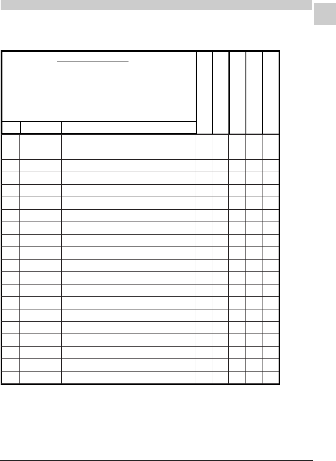
8-11
SRM-HW/HWC 8/99
Service Reference Manual PARTS LISTS
REVISED
1-20-98
REC STOCKING PART
TO SELECT PART #
Last letter of the Model # is the Service Level.
64HWC182A-9A
First find Model #. -------------------------------------------------------------- >
64HWC182A-9(*)
Then match Service Level for desired part. ------------------------------ >
SERVICE LEVEL = *
38HWC182A-9(*)
51HWC182A-9(*)
64HWC182A-9(*)
REF PART # PART DESCRIPTION
HWC182-9 (cont.)
17000B70470GNITNUOMROTOM-DNABE-A111
27400B80470GNITNUOMROTOM-MRAE-A333
37100B33843REWOLB-LEEHWE-A111
47100B01093SGNISUOHREWOLB-YSSAE-A111
68400D23293SCAV073@DFM5.7ROTICAPAC+E-A111
421100-90134REPPUSSENRAHERIW-YSSAE-A111
521100B50693REWOLSSENRAHERIW-YSSAE-A111
621100B08093FFO-TUHSSAG-EVLAVE-A111
721550B13160"05.X"52X"5.61RETLIF+E-A111
031600D70093MARGAIDGNIRIW-LEBALE-A111
052100-41114ROODTUO-LIOCE-A111
552100B08983ROODNI-LIOCE-A111
652200B85093SEBUTPAC-YSSAB-A111
652200-72634SEBUTPAC-YSSAE-C111
262900C521534A-330-TE102WA-PMOCE-A111
762100-28214ESAHP1,PH8/1ROTOM+E-A111
862100B58093NAF-EDALBE-A111
962400D28930TROPPUSROTOM-TEKCARBE-A111
172400D41583CAV073@DFM5/53ROTICAPAC+E-A111
872100C53570ROTCATNOC+E-A111
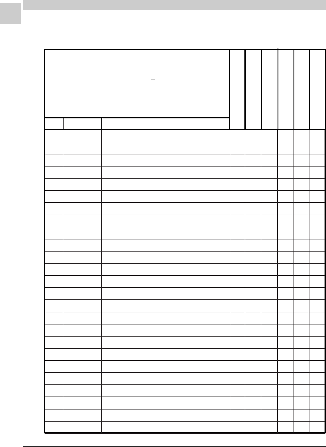
8-12
PARTS LISTS MAGIC-PAK: HW/HWC
SRM-HW/HWC 8/99
REVISED
1-20-98
REC STOCKING PART
TO SELECT PART #
Last letter of the Model # is the Service Level.
64HWC302A-9A
First find Model #. -------------------------------------------------------------- >
64HWC302A-9(*)
Then match Service Level for desired part.------------------------------ >
SERVICE LEVEL = *
51HWC242A-9(*)
64HWC242A-9(*)
51HWC302A-9(*)
REF PART # PART DESCRIPTION
HWC242-302-9
64HWC302A-9(*)
1100B07393REMROFSNART+B-A 1111
5200B92093RETNECREWOLB-LORTNOC+B-A 1111
7100-80134SAG-EVLAV+B-A 1111
11300-47024DLOFINAMB-A1 1
11400-47024DLOFINAMB-A11
31300B03093SAGLARUTAN25#ECIFIROB-A66
31400B03093SAGLARUTAN35#ECIFIROB-A5 5
02100-75914EDORTCELE+B-A 1111
12200-38514EDORTCELE-ERIW+B-A 1111
42100-01134NOITINGI-LORTNOC+B-A 1111
43100-84914RENRUBB-A5656
83110D99983REGNAHCXETAEH-YLBMESSAB-A1 1
83210D99983REGNAHCXETAEH-YLBMESSAB-A11
04100B14883SROTALUBRUTB-A5656
64100B77983REVOCEULF-TEKSAG+B-A 1111
74100B87983DNE.LOCEULF-TEKSAG+B-A 2222
25800A05110TIMIL-LORTNOC+B-A 1111
45100B31193HCTIWSTIMIL-TEKSAGB-A 1111
55400B02573DERTUOLLOR-HCTIWS+B-A 1111
36100-44114TFARDDECUDNI-REWOLB+B-A 1111
96100B64093ESAHP1,PH3/1ROTOM+B-A 1111
17000B70470GNITNUOMROTOM-DNABB-A 1111
27400B80470GNITNUOMROTOM-MRAB-A 3333
37100B33843REWOLB-LEEHWB-A 1111
47100B01093SGNISUOHREWOLB-YLBMESSAB-A 1111
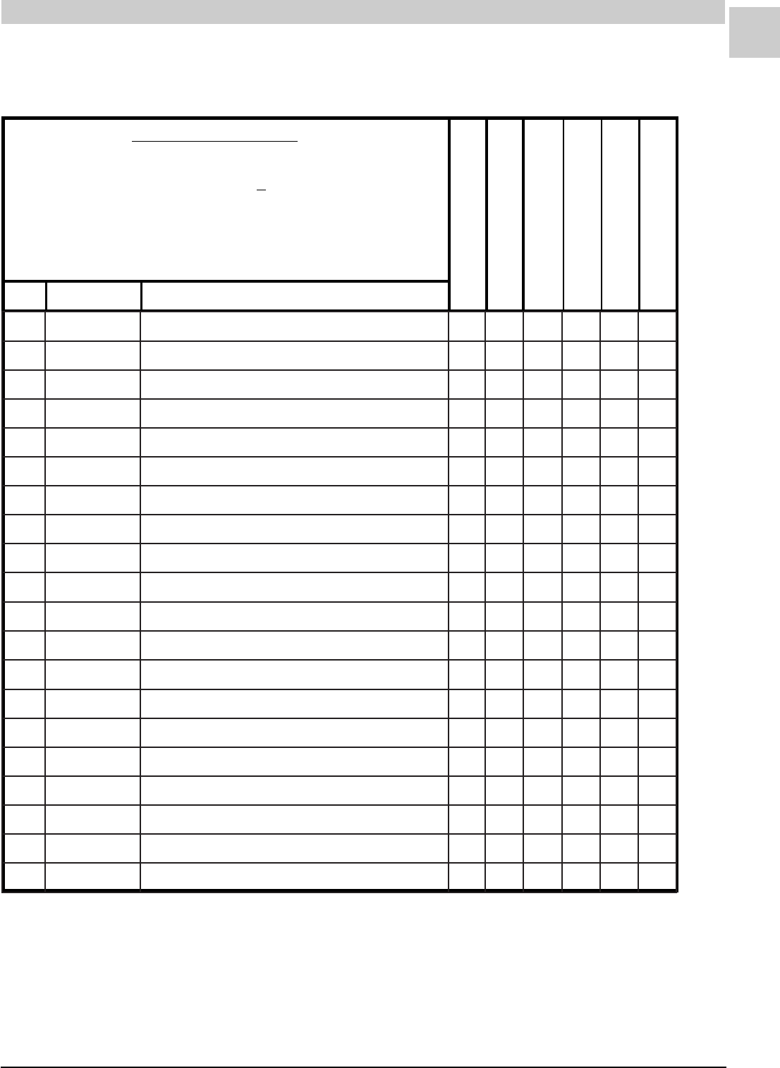
8-13
SRM-HW/HWC 8/99
Service Reference Manual PARTS LISTS
REVISED
1-20-98
REC STOCKING PART
TO SELECT PART #
Last letter of the Model # is the Service Level.
64HWC302A-9A
First find Model #. -------------------------------------------------------------- >
64HWC302A-9(*)
Then match Service Level for desired part.------------------------------ >
SERVICE LEVEL = *
51HWC242A-9(*)
64HWC242A-9(*)
51HWC302A-9(*)
REF PART # PART DESCRIPTION
HWC242-302-9 (cont.)
64HWC302A-9(*)
68400D23293SCAV073@DFM5.7ROTICAPAC+B-A 1111
421100-90134REPPUSSENRAHERIW-YSSAB-A 1111
521100B50693REWOLSSENRAHERIW-YSSAB-A 1111
621100B08093FFO-TUHSSAG-EVLAVB-A 1111
721550B13160"05.X"52X"5.61RETLIF+B-A 1111
031600D70093MARGAIDGNIRIW-LEBALB-A 1111
052100B38983ROODTUO-LIOCB-A11
052100-94604ROODTUO-LIOCB-A11
552100B08983ROODNI-LIOCB-A11
552100-84604ROODNI-LIOCB-A11
652200-17234SEBUTYRALLIPAC-YSSAB-A11
652100-08234SEBUTYRALLIPAC-YSSAB-A11
262500-11824031-VFP-CK42RZ-PMOCB-A11
262600-11824031-VFP-CK82RZ-PMOC 11
762100-45214ESAHP1,PH4/1ROTOM+B-A 1111
862100B26093NAF-EDALBB-A 1111
962400D28930TROPPUSROTOM-TEKCARBB-A 1111
172400D41583CAV073@DFM5/53ROTICAPAC+B-A 1111
672100-52724ROSSERPMOC-GULP+B-A 1111
872100C53570ROTCATNOC+B-A 1111
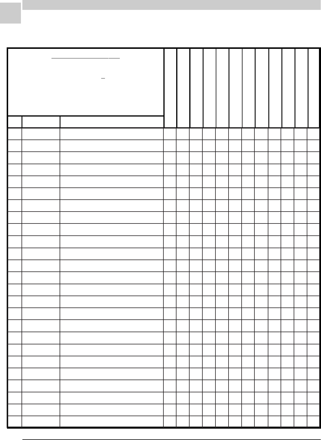
8-14
PARTS LISTS MAGIC-PAK: HW/HWC
SRM-HW/HWC 8/99
REVISED
1-20-98
REC STOCKING PART
TO SELECT PART #
Last letter of the Model # is the Service Level.
64HWC302-8A
First find Model #. ------------------------------------------------ >
64HWC302-8(*)
Then match Service Level for desired part.---------------- >
SERVICE LEVEL = *
51HWC182-8(*)
64HWC182-8(*)
38HWC242-8(*)
51HWC242-8(*)
64HWC242-8(*)
51HWC302-8(*)
REF PART # PART DESCRIPTION
26HWC122-8(*)
38HWC122-8(*)
38HWC182-8(*)
64HWC302-8(*)
HWC-8
1100B07393REMROFSNART +A1111111111
5200B92093RETNECREWOLB-LORTNOC +A1111111111
7100D13093SAG-EVLAV +A1111111111
11100-47024DLOFINAMA1
11200-47024DLOFINAMA111
11300-47024DLOFINAMA111
11400-47024DLOFINAMA111
31300B0309325#ECIFIROA666
31400B0309335#ECIFIROA445455
31500B0309345#ECIFIROA3
02100-75914EDORTCELE +A1111111111
12100-38514EDORTCELE-ERIW +A1111111111
42200-28514NOITINGI-LORTNOC +A1111111111
43100-84914RENRUBA3445645656
83900D99983REGNAHCXETAEH-YSSAA1
83010D99983REGNAHCXETAEH-YSSAA111
83110D99983REGNAHCXETAEH-YSSAA111
83210D99983REGNAHCXETAEH-YSSAA111
04100B14883ROTALUBRUTA3445645656
64100B77983REVOCEULF-TEKSAG +A1111111111
74100B87983DNELOCEULF-TEKSAG +A2222222222
25800A05110TIMIL-LORTNOC +A1111111111
45100B31193HCTIWSTIMIL-TEKSAG A1111111111
55400B02573DERTUOLLOR-HCTIWS +A 111111111
55500B02573NEERGTUOLLOR-HCTIWS+A1
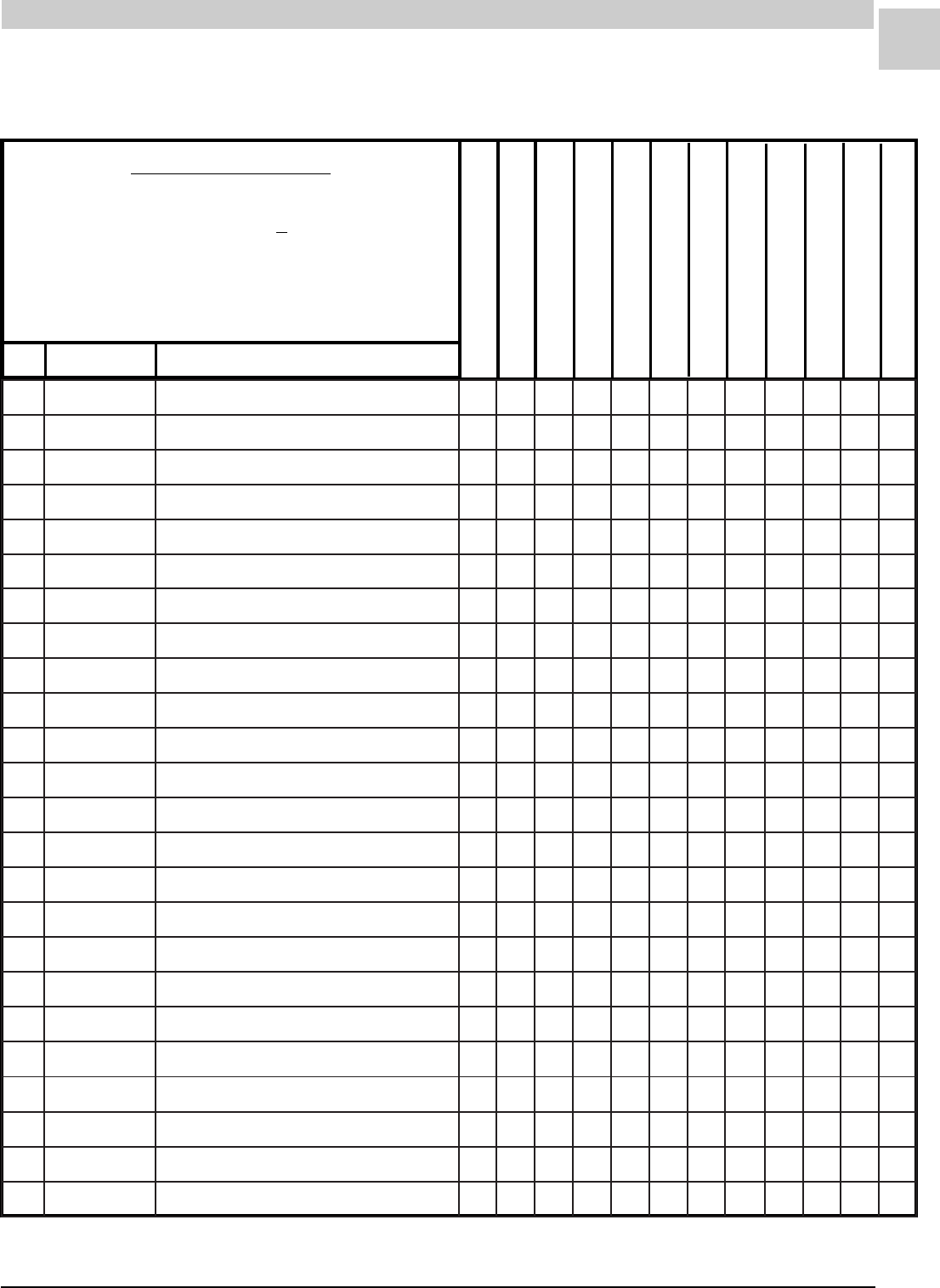
8-15
SRM-HW/HWC 8/99
Service Reference Manual PARTS LISTS
REVISED
1-20-98
REC STOCKING PART
TO SELECT PART #
Last letter of the Model # is the Service Level.
64HWC302-8A
First find Model #. ------------------------------------------------ >
64HWC302-8(*)
Then match Service Level for desired part.---------------- >
SERVICE LEVEL = *
51HWC182-8(*)
64HWC182-8(*)
38HWC242-8(*)
51HWC242-8(*)
64HWC242-8(*)
51HWC302-8(*)
REF PART # PART DESCRIPTION
26HWC122-8(*)
38HWC122-8(*)
38HWC182-8(*)
64HWC302-8(*)
HWC-8 (cont.)
75100-26814DERSSERP-HCTIWS A 111111111
75200-26814NEERGSSERP-HCTIWSA1
36100-44114TFARDDECUDNI-REWOLB +A1111111111
96100B54093ESAHP1,PH6/1ROTOM+A11
96100B64093ESAHP1,PH3/1ROTOM +A 11111111
17000B70470GNITNUOMROTOM-DNAB A1111111111
27400B80470GNITNUOMROTOM-MRA A3333333333
37100B33843REWOLB-LEEHW A1111111111
47100B01093GNISUOHREWOLB-YSSA A1111111111
68100D23293V073@DFM4-ROTICAPAC+A11
68400D23293V073@DFM5.7-ROTICAPAC +A 11111111
421100-86224REPPUSSENRAHERIW-YSSA A1111111111
521100B50693REWOLSSENRAHERIW-YSSA A1111111111
621100B08093FFO-TUHSSAG-EVLAV A1111111111
721640B13160"5.X"52X"5.61RETLIF +A1111111111
821100B23160RETLIF-DOR A1111111111
031500D70093MARGAIDGNIRIW-LEBAL A1111111111
052100B28983ROODTUO-LIOCA11
052100B38983ROODTUO-LIOCA111
052100-94604ROODTUO-LIOCA11
052100-41114ROODTUO-LIOC A 111
552100B97983ROODNI-LIOCA11
552100B08983ROODNI-LIOC A 111111
552100-84604ROODNI-LIOCA11
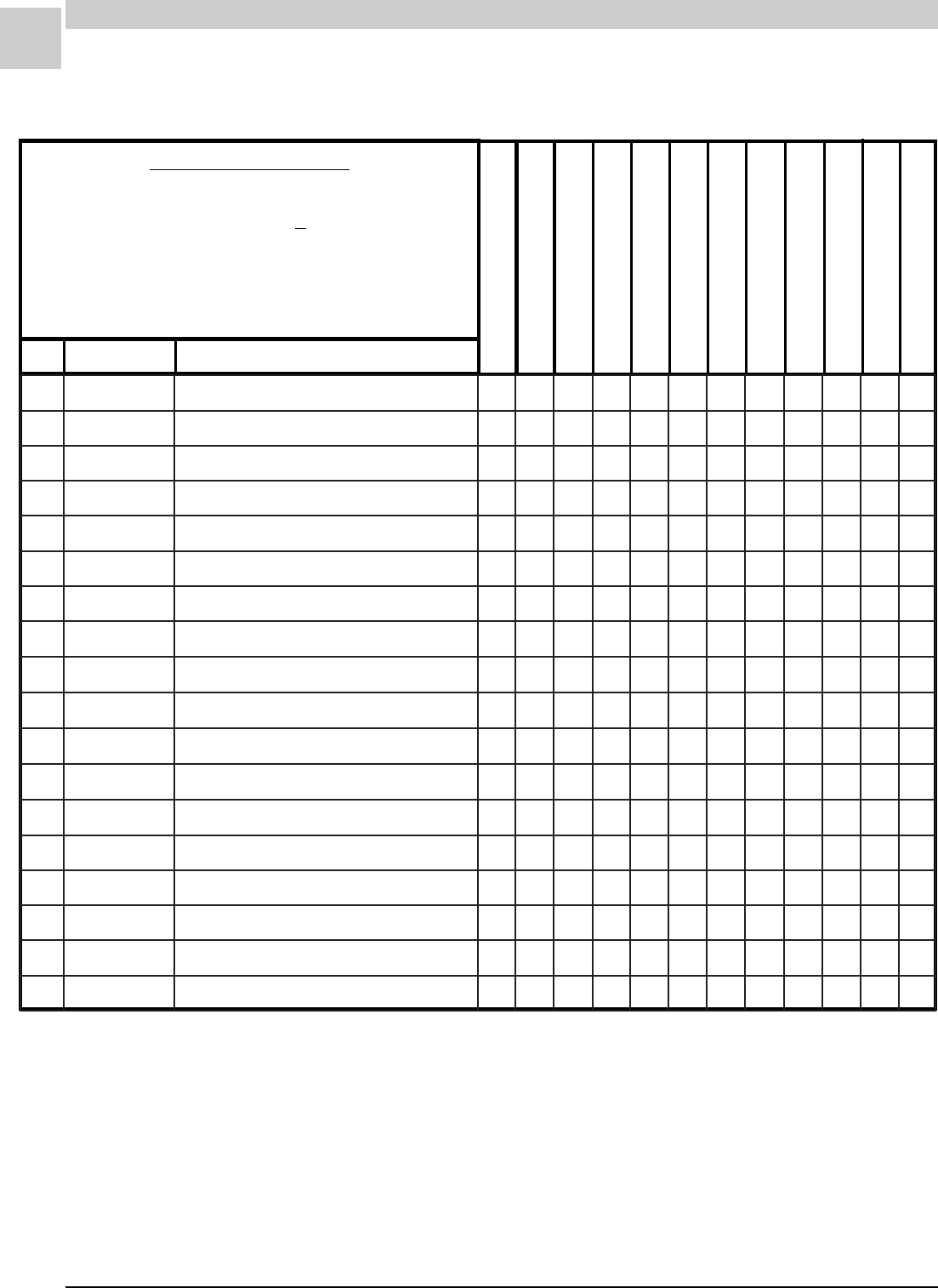
8-16
PARTS LISTS MAGIC-PAK: HW/HWC
SRM-HW/HWC 8/99
REVISED
1-20-98
REC STOCKING PART
TO SELECT PART #
Last letter of the Model # is the Service Level.
64HWC302-8A
First find Model #. ------------------------------------------------ >
64HWC302-8(*)
Then match Service Level for desired part.---------------- >
SERVICE LEVEL = *
51HWC182-8(*)
64HWC182-8(*)
38HWC242-8(*)
51HWC242-8(*)
64HWC242-8(*)
51HWC302-8(*)
REF PART # PART DESCRIPTION
26HWC122-8(*)
38HWC122-8(*)
38HWC182-8(*)
64HWC302-8(*)
HWC-8 (cont.)
652100B85093EBUTPAC-YSSAA11
652200B85093EBUTPAC-YSSA A 111
652300B85093EBUTPAC-YSSAA111
652100-05604EBUTPAC-YSSAA11
262100C63153VFP-1K82RZ-PMOCA11
262500C63153VFP-1K32RZ-PMOCA111
262100C800934A-200-TE741KR-PMOCA11
262200C800934A-900-TE332KR-PMOC A 111
762100-45214ESAHP1,PH4/1ROTOM +A 11111
762100-28214ESAHP1,PH8/1ROTOM +A11111
862100B26093NAF-EDALB A 11111
862100B58093NAF-EDALB A11111
962400D28930TROPPUSROTOM-TEKCARB A1111111111
172200D41583CAV073@DFM5/52-ROTICAPAC +A11111
172300D41583CAV073@DFM5/03-ROTICAPAC+A111
172400D41583CAV073@DFM5/53-ROTICAPAC+A 11
872100C53570ROTCATNOC +A1111111111
282100-51704YALEDEMIT-YALER +A 11111
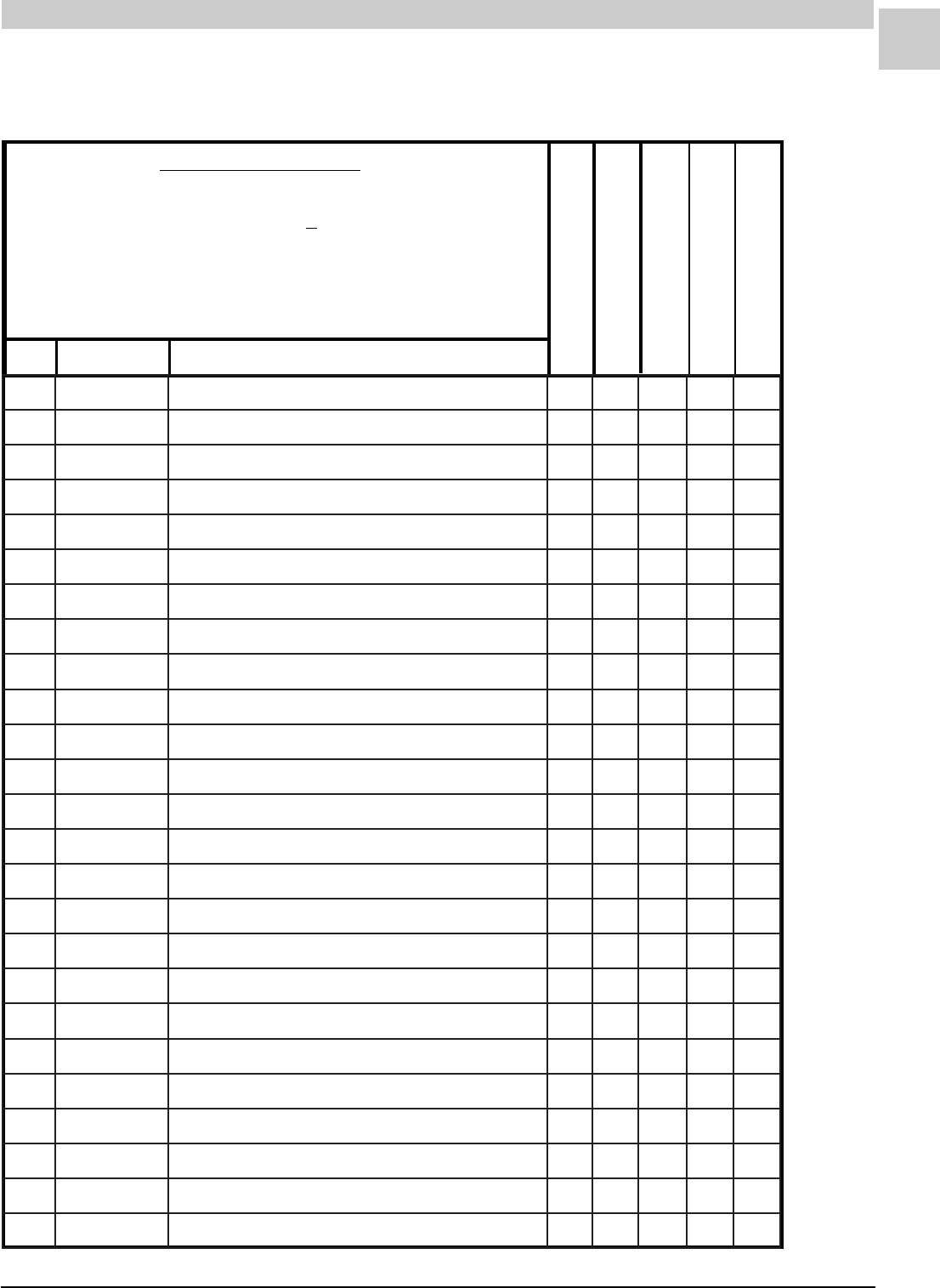
8-17
SRM-HW/HWC 8/99
Service Reference Manual PARTS LISTS
REVISED
1-20-98
REC STOCKING PART
TO SELECT PART #
Last letter of the Model # is the Service Level.
64HWC182-6A
First find Model #. -------------------------------------------------------------- >
64HWC182-6(*)
Then match Service Level for desired part.------------------------------ >
SERVICE LEVEL = *
38HWC182-7(*)
51HWC182-6(*)
64HWC182-6(*)
REF PART # PART DESCRIPTION
HWC-6/7
1100B07393REMROFSNART+A111
5100B92093RETNECREWOLB-LORTNOC+A111
7100D13093SAG-EVLAV+A111
11200B23883LLEC4-DLOFINAMA1
11300B23883LLEC5-DLOFINAMA1
11400B23883LLEC6-DLOFINAMA1
31300B03093SAGLARUTAN25#ECIFIROA6
31400B03093SAGLARUTAN35#ECIFIROA45
02100B05093EDORTCELE+A111
12100-38514EDORTCELE-ERIW+A111
42200-28514NOITINGI-LORTNOC+A111
43100B60093RENRUB-YSSAA456
83010D99983REGNAHCXETAEH-YLBMESSAA1
83110D99983REGNAHCXETAEH-YLBMESSAA1
83210D99983REGNAHCXETAEH-YLBMESSAA1
04100B14883ROTALUBRUTA456
64100B77983REVOCEULF-TEKSAG+A111
74100B87983DNE.LOCEULF-TEKSAG+A222
25800A05110TIMIL-LORTNOC+A111
45100B31193HCTIWSTIMIL-TEKSAGA111
55400B02573DERTUOLLOR-HCTIWS+A111
75100-26814DERSSERP-HCTIWSA111
36100-44114TFARDDECUDNI-REWOLB+A111
96100B64093ESAHP1,PH3/1ROTOM+A111
17000B70470GNITNUOMROTOM-DNABA111
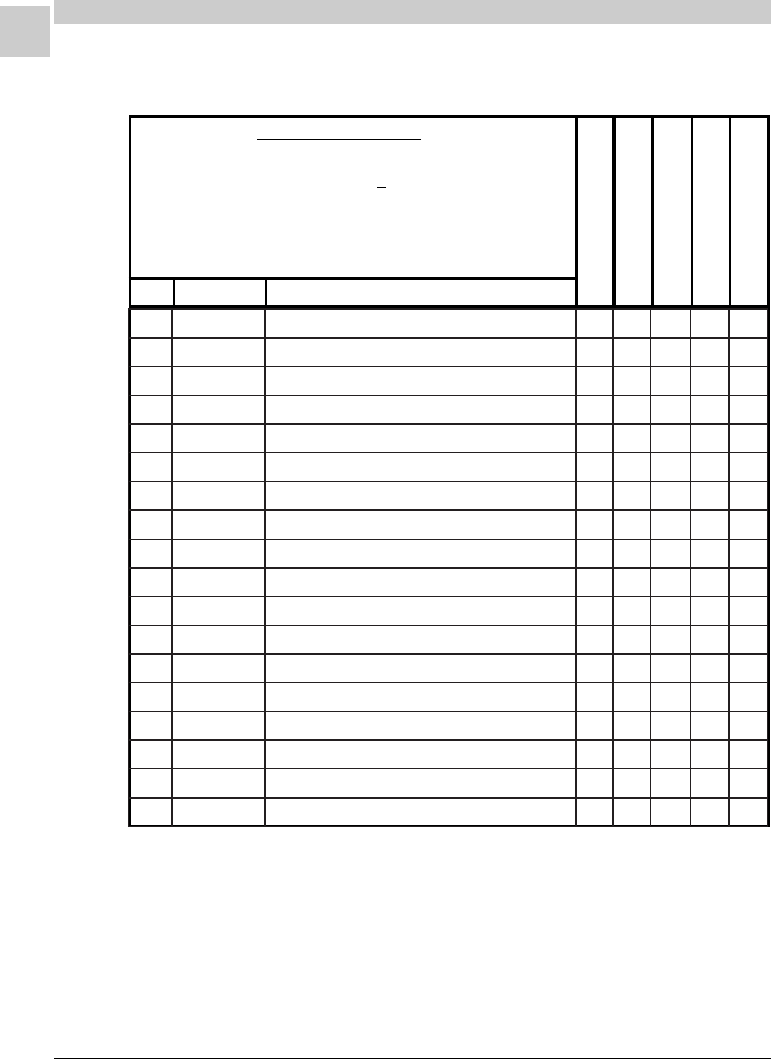
8-18
PARTS LISTS MAGIC-PAK: HW/HWC
SRM-HW/HWC 8/99
REVISED
1-20-98
REC STOCKING PART
TO SELECT PART #
Last letter of the Model # is the Service Level.
64HWC182-6A
First find Model #. -------------------------------------------------------------- >
64HWC182-6(*)
Then match Service Level for desired part.------------------------------ >
SERVICE LEVEL = *
38HWC182-7(*)
51HWC182-6(*)
64HWC182-6(*)
REF PART # PART DESCRIPTION
HWC-6/7 (cont.)
27400B80470GNITNUOMROTOM-MRAA333
37100B33843REWOLBLEEHWA111
47100B01093GNISUOHREWOLB-YSSAA111
68400D23293CAV073@DFM5.7ROTICAPAC+A111
421100B13204ELAMEFSSENRAHERIW-YSSAA111
521100B50693ELAMSSENRAHERIW-YSSAA111
621100B08093FFO-TUHSSAG-EVLAVA111
721640B13160"05.X"52X"5.61RETLIF+A111
821100B23160RETLIF-DORA111
031500D70093MARGAIDGNIRIW-LEBALA111
052100-41114ROODTUO-LIOCA111
552100B08983ROODNI-LIOCA111
262900C52153G7155WA-PMOCA111
762100-28214ESAHP1,PH8/1ROTOMA111
862100B58093NAF-EDALBA111
962400D28930TROPPUSROTOM-TEKCARBA111
172400D41583CAV073@DFM5/53ROTICAPAC+A111
872100C53570ROTCATNOC+A111
8-19
SRM-HW/HWC 8/99
Service Reference Manual PARTS LISTS
REVISED
1-20-98
REC STOCKING PART
TO SELECT PART #
Last letter of the Model # is the Service Level.
64HWC302-5A
First find Model #. ------------------------------------------------ >
64HWC302-5(*)
Then match Service Level for desired part.---------------- >
SERVICE LEVEL = *
51HWC182-5(*)
64HWC182-5(*)
38HWC242-5(*)
51HWC242-4(*)
64HWC242-4(*)
51HWC302-5(*)
REF PART # PART DESCRIPTION
26HWC122-5(*)
38HWC122-5(*)
38HWC182-6(*)
64HWC302-5(*)
HWC-5
1100B07393REMROFSNART +A1111111111
5200B92093RETNECREWOLB-LORTNOC +A1111111111
7100D13093SAG-EVLAV +A1111111111
11100B23883LLEC3-DLOFINAMA1
11200B23883LLEC4-DLOFINAMA111
11300B23883LLEC5-DLOFINAMA111
11400B23883LLEC6-DLOFINAMA111
31300B0309325#ECIFIROA666
31400B0309335#ECIFIROA445455
31500B0309345#ECIFIROA3
02100B05093EDORTCELE +A1111111111
12100-38514EDORTCELE-ERIW +A1111111111
42200-28514NOITINGI-LORTNOC +A1111111111
43100B60093RENRUB-YSSAA3445645656
83900D99983REGNAHCXETAEH-YSSAA1
83010D99983REGNAHCXETAEH-YSSAA111
83110D99983REGNAHCXETAEH-YSSAA111
83210D99983REGNAHCXETAEH-YSSAA111
04100B14883ROTALUBRUTA3445645656
64100B77983REVOCEULF-TEKSAG +A1111111111
74100B87983DNELOCEULF-TEKSAG +A2222222222
25800A05110TIMIL-LORTNOC +A1111111111
45100B31193HCTIWSTIMIL-TEKSAG +A1111111111
55400B02573DERTUOLLOR-HCTIWS +A1111111111
8-20
PARTS LISTS MAGIC-PAK: HW/HWC
SRM-HW/HWC 8/99
REVISED
1-20-98
REC STOCKING PART
TO SELECT PART #
Last letter of the Model # is the Service Level.
64HWC302-5A
First find Model #. ------------------------------------------------ >
64HWC302-5(*)
Then match Service Level for desired part.---------------- >
SERVICE LEVEL = *
51HWC182-5(*)
64HWC182-5(*)
38HWC242-5(*)
51HWC242-4(*)
64HWC242-4(*)
51HWC302-5(*)
REF PART # PART DESCRIPTION
26HWC122-5(*)
38HWC122-5(*)
38HWC182-6(*)
64HWC302-5(*)
HWC-5 (cont.)
75100-26814DERSSERP-HCTIWS A 111111111
75200-26814NEERGSSERP-HCTIWSA1
36100-44114TFARDDECUDNI-REWOLB +A1111111111
96100B54093ESAHP1,PH6/1ROTOM+A11
96100B64093ESAHP1,PH3/1ROTOM +A 11111111
17000B70470GNITNUOMROTOM-DNAB A1111111111
27400B80470GNITNUOMROTOM-MRA A3333333333
37100B33843REWOLB-LEEHW A1111111111
47100B01093GNISUOHREWOLB-YSSA A1111111111
68100D23293V073@DFM4-ROTICAPAC+A11
68400D23293V073@DFM5.7-ROTICAPAC +A 11111111
421100B13204ELAMEFSSENRAHERIW-YSSA A1111111111
521100B50693ELAMSSENRAHERIW-YSSA A1111111111
621100B08093FFO-TUHSSAG-EVLAV +A1111111111
721640B13160"5.X"52X"5.61RETLIF +A1111111111
821100B23160RETLIF-DOR A1111111111
031500D70093MARGAIDGNIRIW-LEBAL A1111111111
052100B28983ROODTUO-LIOCA11
052100B38983ROODTUO-LIOCA111
052100-94604ROODTUO-LIOCA11
052100-41114ROODTUO-LIOC A 111
552100B97983ROODNI-LIOCA11
552100B08983ROODNI-LIOC A 111111
552100-84604ROODNI-LIOCA11
8-21
SRM-HW/HWC 8/99
Service Reference Manual PARTS LISTS
REVISED
1-20-98
REC STOCKING PART
TO SELECT PART #
Last letter of the Model # is the Service Level.
64HWC302-5A
First find Model #. ------------------------------------------------ >
64HWC302-5(*)
Then match Service Level for desired part.---------------- >
SERVICE LEVEL = *
51HWC182-5(*)
64HWC182-5(*)
38HWC242-5(*)
51HWC242-4(*)
64HWC242-4(*)
51HWC302-5(*)
REF PART # PART DESCRIPTION
26HWC122-5(*)
38HWC122-5(*)
38HWC182-6(*)
64HWC302-5(*)
HWC-5 (cont.)
652100B85093EBUTPAC-YSSAA11
652200B85093EBUTPAC-YSSA A 111
652300B85093EBUTPAC-YSSAA111
652100-05604EBUTPAC-YSSAA11
262100C63153VFP-1K82RZ-PMOCA11
262500C63153VFP-1K32RZ-PMOCA111
262100C800934A-200-TE741KR-PMOCA11
262200C800934A-900-TE332KR-PMOC A 111
762100-45214ESAHP1,PH4/1ROTOM +A 11111
762100-28214ESAHP1,PH8/1ROTOM +A11111
862100B26093NAF-EDALB A 11111
862100B58093NAF-EDALB A11111
962400D28930TROPPUSROTOM-TEKCARB A1111111111
172200D41583CAV073@DFM5/52-ROTICAPAC +A11111
172300D41583CAV073@DFM5/03-ROTICAPAC+A111
172400D41583CAV073@DFM5/53-ROTICAPAC+A 11
872100C53570ROTCATNOC +A1111111111
282100-51704YALEDEMIT-YALER +A 11111
8-22
PARTS LISTS MAGIC-PAK: HW/HWC
SRM-HW/HWC 8/99
REVISED
1-20-98
REC STOCKING PART
TO SELECT PART #
Last letter of the Model # is the Service Level.
38HWC182-4A
First find Model #. -------------------------------------------------------------- >
38HWC182-4(*)
Then match Service Level for desired part.------------------------------ >
SERVICE LEVEL = *
51HWC182-4(*)
64HWC182-4(*)
51HWC302-4(*)
REF PART # PART DESCRIPTION
64HWC302-4(*)
38HWC182-4(*)
HWC-4
1100B07393REMROFSNART +A11111
5200B92093RETNECREWOLB-LORTNOC +A11111
7100D13093SAG-EVLAV +A11111
11200B23883DLOFINAMA1
11300B23883DLOFINAMA11
11400B23883DLOFINAMA11
31300B03093SAGLARUTAN25#ECIFIROA66
31400B03093SAGLARUTAN35#ECIFIROA455
91100B37093EMALF-ROSNES +A11111
02100B05093EDORTCELE +A11111
12100B94093EDORTCELE-ERIW+A1
12200B94093EDORTCELE-ERIW +A 1111
42100B84093NOITINGI-LORTNOC +A11111
43100B60093TOHSDNERENRUBA45656
83200D99983REGNAHCXETAEHA1
83300D99983REGNAHCXETAEHA11
83400D99983REGNAHCXETAEH 11
04100B14883SROTALUBRUTA45656
64100B77983TNORFEULF-TEKSAG +A11111
74100B87983EDISEULF-TEKSAG +A22222
25800A05110TIMIL-LORTNOC +A11111
45100B31193HCTIWSTIMIL-TEKSAG +A11111
55400B02573TUOLLOR-HCTIWS +A11111
75100B98093ERUSSERP.O.N-HCTIWS A11111
36100B50093TFARDDECUDNI-REWOLB +A11111
8-23
SRM-HW/HWC 8/99
Service Reference Manual PARTS LISTS
REVISED
1-20-98
REC STOCKING PART
TO SELECT PART #
Last letter of the Model # is the Service Level.
38HWC182-4A
First find Model #. -------------------------------------------------------------- >
38HWC182-4(*)
Then match Service Level for desired part.------------------------------ >
SERVICE LEVEL = *
51HWC182-4(*)
64HWC182-4(*)
51HWC302-4(*)
REF PART # PART DESCRIPTION
64HWC302-4(*)
38HWC182-4(*)
HWC-4 (cont.)
96100B64093PH3/1ROTOM +A11111
17000B70470GNITNUOMROTOM-DNAB A11111
27400B80470GNITNUOMROTOM-MRA A33333
37100B33843REWOLB-LEEHW A11111
47100B01093REWOLB-GNISUOH A11111
68400D23293CAV073@DFM5.7ROTICAPAC +A11111
421100B13204.TPCERELAMEF-YSSA A11111
521100B056093.TPCERELAM-YSSA A11111
621100B08093FFO-TUHSSAG-EVLAV +A11111
721640B13160"05.X"52X"5.61RETLIF +A11111
821100B23160RETLIF-DOR A11111
031300D70093MARGAIDGNIRIW A11111
052100-94604ROODTUO-LIOCA11
052100-41114ROODTUO-LIOCA111
552100B08983ROODNI-LIOCA111
552100-84604ROODNI-LIOCA11
652200B85093REIRD-YSSAEBUTPACA111
652100-05604REIRD-YSSAEBUTPACA11
262100C63153ROSSERPMOCA11
262200C80093ROSSERPMOCA111
762100B44093PH4/1ROTOM+A11
762100B48093PH8/1ROTOM+A111
862100B26093NAF-EDALBA11
862100B58093NAF-EDALBA111
962400D28930TROPPUSROTOM-TEKCARB A11111
8-24
PARTS LISTS MAGIC-PAK: HW/HWC
SRM-HW/HWC 8/99
REVISED
1-20-98
REC STOCKING PART
TO SELECT PART #
Last letter of the Model # is the Service Level.
38HWC182-4A
First find Model #. -------------------------------------------------------------- >
38HWC182-4(*)
Then match Service Level for desired part.------------------------------ >
SERVICE LEVEL = *
51HWC182-4(*)
64HWC182-4(*)
51HWC302-4(*)
REF PART # PART DESCRIPTION
64HWC302-4(*)
38HWC182-4(*)
HWC-4 (cont.)
172200D41583CAV073@DFM5/52ROTICAPAC+A111
172400D41583CAV073@DFM5/53ROTICAPAC+A11
872100C53570ROTCATNOC +A11111
282100A56083YALEDEMIT-YALER+A11
103200B95093REIRD+A111
103300B95093REIRD+A11
8-25
SRM-HW/HWC 8/99
Service Reference Manual PARTS LISTS
REVISED
1-20-98
REC STOCKING PART
TO SELECT PART #
Last letter of the Model # is the Service Level.
64HWC302-3A
First find Model #. ------------------------------------------------ >
64HWC302-3(*)
Then match Service Level for desired part.---------------- >
SERVICE LEVEL = *
51HWC182-3(*)
64HWC182-3(*)
38HWC242-3(*)
51HWC242-3(*)
64HWC242-3(*)
51HWC302-3(*)
REF PART # PART DESCRIPTION
26HWC122-3(*)
38HWC122-3(*)
38HWC182-3(*)
64HWC302-3(*)
HWC-3
1100B07393REMROFSNART +A1111111111
5100B92093.TNOC.OLBRETNEC +A1111111111
7100D13093SAG-EVLAV +A1111111111
11100B23883SAGDLOFINAMA1
11200B23883SAGDLOFINAMA111
11300B23883SAGDLOFINAMA111
11400B23883SAGDLOFINAMA111
31300B0309325#ECIFIROA666
31400B0309335#ECIFIROA445455
31500B0309345#ECIFIROA3
91100B37093EMALF-ROSNES +A1111111111
02100B05093.I.S.D-EDORTCELE +A1111111111
12100B94093EDORTCELE-ERIW+A1111
12200B94093EDORTCELE-ERIW +A 11 1111
42100B84093NOITINGI-LORTNOC +A1111111111
43100B60093TOHSDNERENRUBA3445645656
83100D99983REGNAHCXETAEHA1
83200D99983REGNAHCXETAEHA111
83300D99983REGNAHCXETAEHA111
83400D99983REGNAHCXETAEHA111
04100B14883ROTALUBRUTA3445645656
64100B77983TNORFEULFTEKSAG +A1111111111
74100B87983EDISEULFTEKSAG +A2222222222
25800A05110TIMIL-LORTNOC +A1111111111
45100B31193HCTIWSTIMIL-TEKSAG +A1111111111

8-26
PARTS LISTS MAGIC-PAK: HW/HWC
SRM-HW/HWC 8/99
REVISED
1-20-98
REC STOCKING PART
TO SELECT PART #
Last letter of the Model # is the Service Level.
64HWC302-3A
First find Model #. ------------------------------------------------ >
64HWC302-3(*)
Then match Service Level for desired part.---------------- >
SERVICE LEVEL = *
51HWC182-3(*)
64HWC182-3(*)
38HWC242-3(*)
51HWC242-3(*)
64HWC242-3(*)
51HWC302-3(*)
REF PART # PART DESCRIPTION
26HWC122-3(*)
38HWC122-3(*)
38HWC182-3(*)
64HWC302-3(*)
HWC-3 (cont.)
55400B02573TUOLLOR-HCTIWS
+
A1111111111
75100B68093ERUSSERP.O.NHCTIWS A 111111111
75200B68093ERUSSERP.O.NHCTIWSA1
36100B50093TFARDDECUDNI-REWOLB +A1111111111
96100B54093PH6/1ROTOM+A11
96100B64093PH3/1ROTOM +A 11111111
17000B70470GNITNUOMROTOM-DNAB A1111111111
27400B80470GNITNUOMROTOM-MRA A3233333333
37100B33843REWOLB-LEEHW A1111111111
47100B01093REWOLB-GNISUOH A1111111111
68100D100434OLBROTICAPAC+A11
68400D100435.7OLBROTICAPAC +A 11111111
421100B66393.TPCERELAMEF-YSSA A1111111111
521100B50693YSSA.PCERELAM A1111111111
621100B08093FFO-TUHSSAG-EVLAV +A1111111111
721640B13160RIA-RETLIF +A1111111111
821100B23160RETLIF-DOR A1111111111
031200D70093MARGAIDGNIRIW-LEBAL A1111111111
052100B28983ROODTUO-LIOCA11
052100B38983ROODTUO-LIOC A 111111
052100B48983ROODTUO-LIOCA11
552100B97983ROODNI-LIOCA11
552100B08983ROODNI-LIOC A 111111
552100B18983ROODNI-LIOCA11
8-27
SRM-HW/HWC 8/99
Service Reference Manual PARTS LISTS
REVISED
1-20-98
REC STOCKING PART
TO SELECT PART #
Last letter of the Model # is the Service Level.
64HWC302-3A
First find Model #. ------------------------------------------------ >
64HWC302-3(*)
Then match Service Level for desired part.---------------- >
SERVICE LEVEL = *
51HWC182-3(*)
64HWC182-3(*)
38HWC242-3(*)
51HWC242-3(*)
64HWC242-3(*)
51HWC302-3(*)
REF PART # PART DESCRIPTION
26HWC122-3(*)
38HWC122-3(*)
38HWC182-3(*)
64HWC302-3(*)
HWC-3 (cont.)
652100B75093YSSAEBUTPACA11
652100B85093YSSAEBUTPACA11
652200B85093YSSAEBUTPAC A 111
652300B85093YSSAEBUTPACA111
262100C63153ROSSERPMOCA11
262500C63153ROSSERPMOCA111
262100C80093ROSSERPMOCA11
262200C80093ROSSERPMOC A 111
762100B44093PH4/1NAFROTOM +A 11111
762100B48093PH8/1NAFROTOM +A11111
862100B26093NAF-EDALB A 11111
862100B58093NAF-EDALB A11111
962400D28930TROPPUSROTOM-TEKCARB A1111111111
172200D41583CAV073@DFM5/52-ROTICAPAC +A11111
172300D41583CAV073@DFM5/03-ROTICAPAC+A111
172400D41583CAV073@DFM5/53-ROTICAPAC+A 11
872100B85653ROTCATNOC +A1111111111
282100A56083YALEDEMIT-YALER +A1111111111
103100B95093REIRD-RETLIF+A11
103200B95093REIRD-RETLIF +A 111111
103300B95093REIRD-RETLIF+A 11
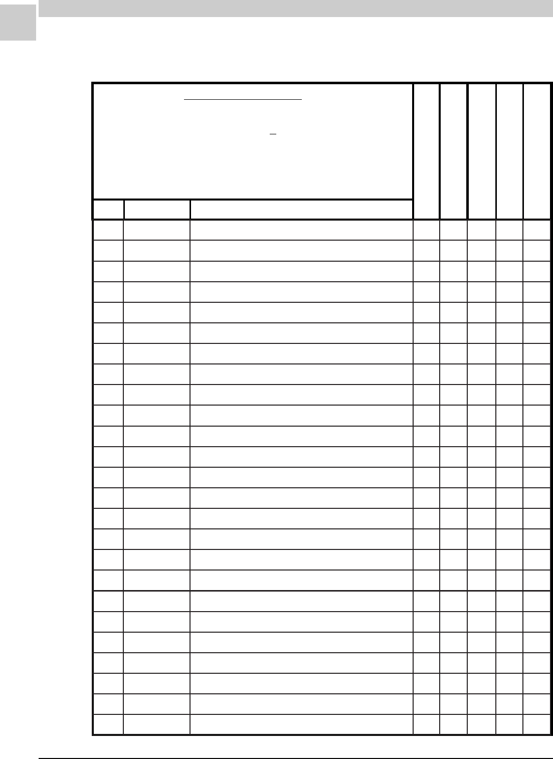
8-28
PARTS LISTS MAGIC-PAK: HW/HWC
SRM-HW/HWC 8/99
REVISED
1-20-98
REC STOCKING PART
TO SELECT PART #
Last letter of the Model # is the Service Level.
64HWC182-2A
First find Model #. -------------------------------------------------------------- >
64HWC182-2(*)
Then match Service Level for desired part.------------------------------ >
SERVICE LEVEL = *
38HWC182-2(*)
51HWC182-2(*)
64HWC182-2(*)
REF PART # PART DESCRIPTION
HWC-2
1100D13093SREGDOR-ETIHWSAG-EVLAV+A111
3100B94093EDORTCELE-ERIW+A1
3200B94093EDORTCELE-ERIW+A11
4100B92093.TNOC.OLBRETNEC+A111
5100B84093NOITINGI-LORTNOC+A111
6100B37093EMALF-ROSNES+A111
01100B05093.I.S.D-EDORTCELE+A111
61800A05110TIMIL-LORTNOC+A111
81100B01663REMROFSNART+A111
52100B08983ROODNI-LIOCA111
62200B85093YSSAEBUTPACA111
82300B0309325#ECIFIROA56
82400B0309335#DUPSECIFIROA4
33200D99983REGNAHCXETAEHA1
33300D99983REGNAHCXETAEHA1
33400D99983REGNAHCXETAEHA1
53100B14883ROTALUBRUTA456
83100B77983TNORFEULFTEKSAG+A111
83100B87983EDISEULFTEKSAG+A222
74100B60093TOHSDNERENRUBA456
84200B23883SAGDLOFINAMA1
84300B23883SAGDLOFINAMA1
84400B23883SAGDLOFINAMA1
55100B68093ERUSSERP.O.NHCTIWSA111
65100B50093.D.IREWOLB+A111
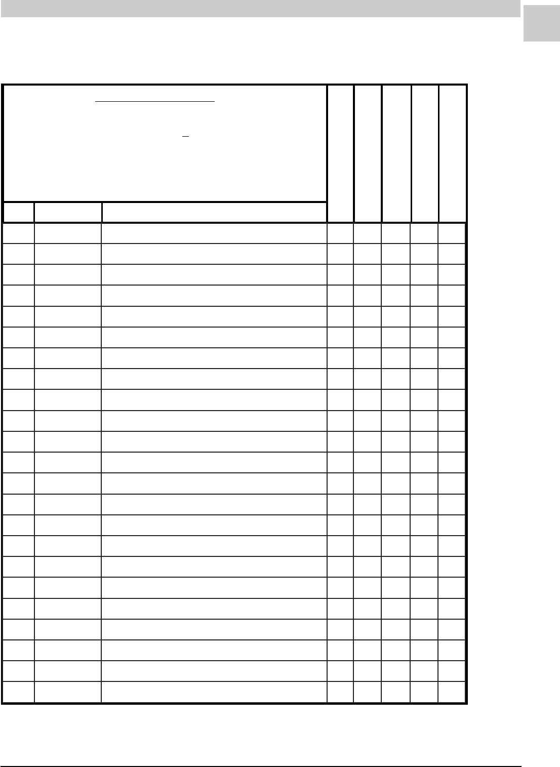
8-29
SRM-HW/HWC 8/99
Service Reference Manual PARTS LISTS
REVISED
1-20-98
REC STOCKING PART
TO SELECT PART #
Last letter of the Model # is the Service Level.
64HWC182-2A
First find Model #. -------------------------------------------------------------- >
64HWC182-2(*)
Then match Service Level for desired part.------------------------------ >
SERVICE LEVEL = *
38HWC182-2(*)
51HWC182-2(*)
64HWC182-2(*)
REF PART # PART DESCRIPTION
HWC-2 (cont.)
26400B02573TUOLLORHCTIWS+A111
96100B66393SSENRAHERIW-YSSAA111
37100B08093FFO-TUHSSAG-EVLAV+A111
47100B31193HCTIWSTIMIL-TEKSAG+A111
67400D100435.7OLBROTICAPAC+A111
08100B64093PH3/1ROTOM+A111
18000B70470GNITNUOMROTOM-DNABA111
28400B80470GNITNUOMROTOM-MRAA333
38100B33843REWOLB-LEEHWA111
48100B01093REWOLB-GNISUOHA111
69100D70093MARGAIDGNIRIWA111
79640B13160RETLIFRIA+A111
89100B23160RETLIF-DORA111
052100B38983ROODTUO-LIOCA111
552100B85653ROTCATNOC+A111
062200C80093ROSSERPMOCA111
072200D415835/52ROTICAPAC+A111
272100B44093PH4/1NAFROTOM+A111
372400D28930TROPPUSROTOMTEKCARBA111
972100B26093NAF-EDALBA111
092100B81193.YSSA.PCERELAMA111
823200B95093REIRD+A111
843100A56083YALEDEMIT-YALER+A111
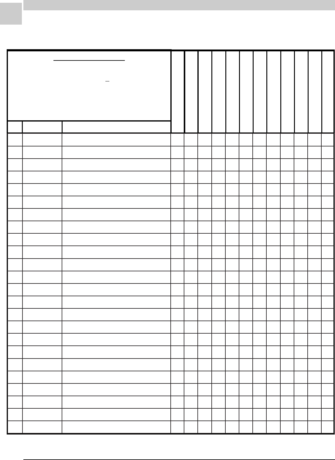
8-30
PARTS LISTS MAGIC-PAK: HW/HWC
SRM-HW/HWC 8/99
REC STOCKING PART
TO SELECT PART #
Last letter of the Model # is the Service Level.
64HWC302-1A
First find Model #. ------------------------------------------------ >
64HWC302-1(*)
Then match Service Level for desired part.---------------- >
SERVICE LEVEL = *
51HWC182-1(*)
64HWC182-1(*)
38HWC242-1(*)
51HWC242-1(*)
64HWC242-1(*)
51HWC302-1(*)
REF PART # PART DESCRIPTION
26HWC122-1(*)
38HWC122-1(*)
38HWC182-1(*)
64HWC302-1(*)
REVISED
1-20-98
HWC-1
1100D13093SREGDOR-ETIHWSAG-EVLAV +A1111111111
3100B94093EDORTCELE-ERIW+A1111
3200B94093EDORTCELE-ERIW +A 11 1111
4100B92093.TNOC.OLBRETNEC +A1111111111
5200B84093NOITINGI-LORTNOC +A1111111111
6100B37093EMALF-ROSNES +A1111111111
01100B05093.I.S.D-EDORTCELE +A1111111111
61800A05110TIMIL-LORTNOC +A1111111111
81100B01663REMROFSNART +A1111111111
52100B97983ROODNI-LIOCA11
52100B08983ROODNI-LIOC A 111111
52100B18983ROODNI-LIOCA11
62100B75093YSSAEBUTPACA11
62100B85093YSSAEBUTPACA11
62200B75093YSSAEBUTPAC A 111
62300B75093YSSAEBUTPACA111
82300B0309325#ECIFIRO A 56 5656
82400B0309335#DUPSECIFIROA444
82500B0309345#DUPSECIFIROA3
33100D99983REGNAHCXETAEHA1
33200D99983REGNAHCXETAEHA111
33300D99983REGNAHCXETAEHA111
33400D99983REGNAHCXETAEHA111
53100B14883ROTALUBRUTA3445645656
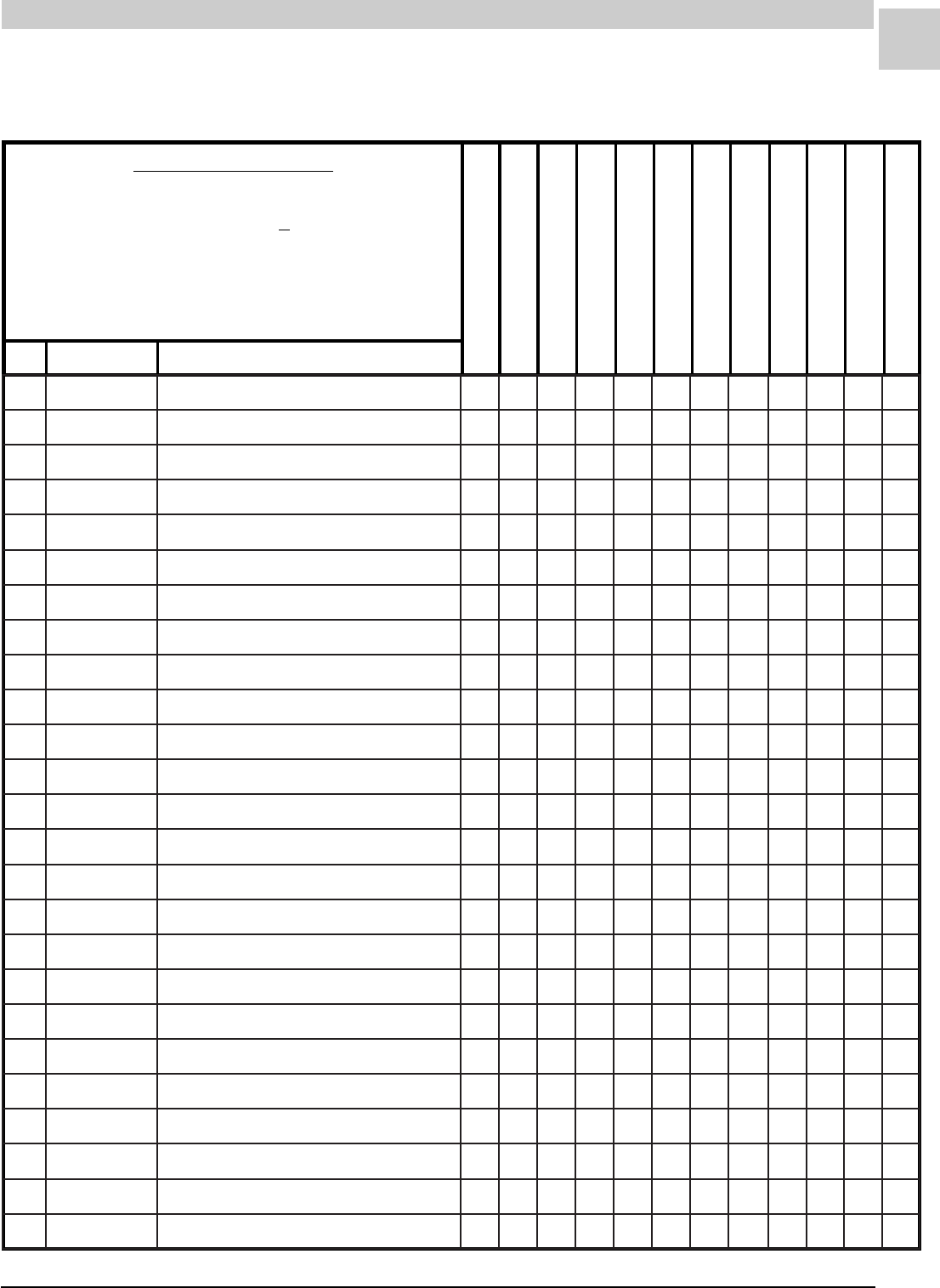
8-31
SRM-HW/HWC 8/99
Service Reference Manual PARTS LISTS
REVISED
1-20-98
REC STOCKING PART
TO SELECT PART #
Last letter of the Model # is the Service Level.
64HWC302-1A
First find Model #. ------------------------------------------------ >
64HWC302-1(*)
Then match Service Level for desired part.---------------- >
SERVICE LEVEL = *
51HWC182-1(*)
64HWC182-1(*)
38HWC242-1(*)
51HWC242-1(*)
64HWC242-1(*)
51HWC302-1(*)
REF PART # PART DESCRIPTION
26HWC122-1(*)
38HWC122-1(*)
38HWC182-1(*)
64HWC302-1(*)
HWC-1 (cont.)
83100B77983TNORFEULFTEKSAG A1111111111
83100B87983EDISEULFTEKSAG A2222222222
74100B60093TOHSDNERENRUBA3445645656
84100B23883SAGDLOFINAMA1
84200B23883SAGDLOFINAMA111
84300B23883SAGDLOFINAMA111
84400B23883SAGDLOFINAMA111
55100B68093ERUSSERP.O.NHCTIWS A 111111111
55200B68093ERUSSERP.O.NHCTIWSA1
65100B50093.D.IREWOLB +A1111111111
26400B02573TUOLLOR-HCTIWS +A1111111111
96100B66393SSENRAHERIW-YSSA A1111111111
37100B08093FFO-TUHSSAG-EVLAV +A1111111111
47100B31193HCTIWSTIMIL-TEKSAG +A1111111111
67100D100434OLBROTICAPAC+A11
67400D100435.7OLBROTICAPAC +A 11111111
08100B54093PH6/1ROTOM+A11
08100B64093PH3/1ROTOM +A 11111111
18000B70470GNITNUOMROTOM-DNAB A1111111111
28400B80470GNITNUOMROTOM-MRA A3233333333
38100B33843REWOLB-LEEHW A1111111111
48100B01093REWOLB-GNISUOH A1111111111
69100D70093MARGAIDGNIRIW A1111111111
79640B13160RIA-RETLIF +A1111111111
89100B23160RETLIF-DOR A1111111111
8-32
PARTS LISTS MAGIC-PAK: HW/HWC
SRM-HW/HWC 8/99
REC STOCKING PART
TO SELECT PART #
Last letter of the Model # is the Service Level.
64HWC302-1A
First find Model #. ------------------------------------------------ >
64HWC302-1(*)
Then match Service Level for desired part.---------------- >
SERVICE LEVEL = *
51HWC182-1(*)
64HWC182-1(*)
38HWC242-1(*)
51HWC242-1(*)
64HWC242-1(*)
51HWC302-1(*)
REF PART # PART DESCRIPTION
26HWC122-1(*)
38HWC122-1(*)
38HWC182-1(*)
64HWC302-1(*)
REVISED
1-20-98
HWC-1 (cont.)
052100B28983ROODTUOLIOCA11
052100B38983ROODTUOLIOC A 111111
052100B48983ROODTUOLIOCA11
552100B85653ROTCATNOC A1111111111
062100C63153ROSSERPMOCA11
062400C63153ROSSERPMOC A 111
062500C63153ROSSERPMOCA111
062100C80093ROSSERPMOCA11
072200D41583CAV073@DFM5/52-ROTICAPAC +A11111
072300D41583CAV073@DFM5/03-ROTICAPAC+A111
072400D41583CAV073@DFM5/53-ROTICAPAC+A 11
272100B44093PH4/1NAFROTOM +A 11111111
272100B48093PH8/1NAFROTOM+A11
372400D28930.PUSROTOMTEKCARB A1111111111
972100B26093NAF-EDALB A 11111111
972100B58093NAF-EDALBA11
092100B81193YSSA.PCERELAM A1111111111
823100B95093REIRD-RETLIF+A11
823200B95093REIRD-RETLIF +A 111111
823300B95093REIRD-RETLIF+A 11
843100A56083YALEDEMIT-YALER +A1111111111
8-33
SRM-HW/HWC 8/99
Service Reference Manual PARTS LISTS
REVISED
1-20-98
REC STOCKING PART
TO SELECT PART #
Last letter of the Model # is the Service Level.
64HW-1A
First find Model #. -------------------------------------------------------------- >
64HW-1(*)
Then match Service Level for desired part.------------------------------ >
SERVICE LEVEL = *
26HW-1(*)
38HW-1(*)
REF PART # PART DESCRIPTION
HW-1
51HW-1(*)
64HW-1(*)
1100D13093SREGDOR-ETIHWSAG-EVLAV 1111
3100B94093EDORTCELE-ERIW11
3200B94093EDORTCELE-ERIW 11
4100B84293.TNOC.OLBRETNEC 1111
5100B84093NOITINGI-LORTNOC 1111
6100B37093EMALF-ROSNES 1111
01100B05093.I.S.D-EDORTCELE 1111
61800A05110TIMIL-LORTNOC 1111
81100B07393REMROFSNART 1111
82300B0309325#ECIFIRO 56
82400B03093DUPSECIFIRO4
82500B03093DUPSECIFIRO3
33100D99983REGNAHCXETAEH1
33200D99983REGNAHCXETAEH1
33300D99983REGNAHCXETAEH 1
33400D99983REGNAHCXETAEH 1
53100B14883ROTALUBRUT3456
83100B77983TNORFEULFTEKSAG 1111
83100B87983EDISEULFTEKSAG 2222
74100B60093TOHSDNERENRUB3456
84100B23883SAGDLOFINAM1
84200B23883SAGDLOFINAM1
84300B23883SAGDLOFINAM 1
84400B23883SAGDLOFINAM 1
8-34
PARTS LISTS MAGIC-PAK: HW/HWC
SRM-HW/HWC 8/99
REVISED
1-20-98
HW-1 (cont.)
REC STOCKING PART
TO SELECT PART #
Last letter of the Model # is the Service Level.
64HW-1A
First find Model #. -------------------------------------------------------------- >
64HW-1(*)
Then match Service Level for desired part.------------------------------ >
SERVICE LEVEL = *
26HW-1(*)
38HW-1(*)
REF PART # PART DESCRIPTION
51HW-1(*)
64HW-1(*)
55100B68093ERUSSERP.O.NHCTIWS 111
55200B68093ERUSSERP.O.NHCTIWS1
65100B50093TFARDDECUDNI-REWOLB 1111
26400B02573TUOLLORHCTIWS 1111
96100B66393SSENRAHERIW-YSSA 1111
37100B08093FFO-TUHSSAG-EVLAV 1111
47100B31193HCTIWSTIMIL-TEKSAG 1111
67100D100434OLBROTICAPAC11
67400D100435.7OLBROTICAPAC 11
08100B54093PH6/1ROTOM11
08100B64093PH3/1ROTOM 11
18000B70470GNITNUOMROTOM-DNAB 1111
28400B80470GNITNUOMROTOM-MRA 3333
38100B33843REWOLB-LEEHW 1111
48100B01093REWOLB-GNISUOH 1111
69100D74293MARGAIDGNIRIW 1111
79640B13160RETLIFRIA 1111
89100B23160RETLIF-DOR 1111
8-35
SRM-HW/HWC 8/99
Service Reference Manual PARTS LISTS
HWA-9 REVISED
4-26-99
REC STOCKING PART
TO SELECT PART #
Last letter of the Model # is the Service Level.
64HWA-9A
First find Model #. -------------------------------------------------------------- >
64HWA-9(*)
Then match Service Level for desired part. ------------------------------ >
SERVICE LEVEL = *
26HWA-9(*)
38HWA-9(*)
51HWA-9(*)
64HWA-9(*)
REF PART # PART DESCRIPTION
1100B07393REMROFSNART +A1111
7100-78944LLEWYENOHSAG-EVLAV +A1111
11100-47024DLOFINAMA1
11200-47024DLOFINAMA1
11300-47024DLOFINAMA1
11400-47024DLOFINAMA1
31300B03093SAGLARUTAN25#ECIFIROA6
31400B03093SAGLARUTAN35#ECIFIROA45
31500B03093SAGLARUTAN45#ECIFIROA3
02100-29944EDORTCELE +A1111
12100-39944EDORTCELE-ERIW +A1111
42100-09944REWOLB/NOITINGI-LORTNOC +A1111
43100-84914RENRUBA3456
83900D99983REGNAHCXETAEH-YLBMESSAA1
83010D99983REGNAHCXETAEH-YLBMESSAA1
83110D99983REGNAHCXETAEH-YLBMESSAA1
83210D99983REGNAHCXETAEH-YLBMESSAA1
04100B14883SROTALUBRUTA3456
64100B77983REVOCEULF-TEKSAG +A1111
74100B87983DNE.LOCEULF-TEKSAG +A2222
25700B45104TIMIL-LORTNOC +A1111
55400B02573DERTUOLLOR-HCTIWS +A 111
55500B02573NEERGTUOLLOR-HCTIWS+A1
75010-91844DERERUSSERP-HCTIWS A1111
36100-44114TFARDDECUDNI-REWOLB +A1111
8-36
PARTS LISTS MAGIC-PAK: HW/HWC
SRM-HW/HWC 8/99
HWA-9 (cont.) REVISED
4-26-99
REC STOCKING PART
TO SELECT PART #
Last letter of the Model # is the Service Level.
64HWA-9A
First find Model #. -------------------------------------------------------------- >
64HWA-9(*)
Then match Service Level for desired part. ------------------------------ >
SERVICE LEVEL = *
26HWA-9(*)
38HWA-9(*)
51HWA-9(*)
64HWA-9(*)
REF PART # PART DESCRIPTION
96100B54093ESAHP1,PH6/1ROTOM+A11
96100B64093ESAHP1,PH3/1ROTOM+A11
17000B70470GNITNUOMROTOM-DNAB A1111
27400B80470GNITNUOMROTOM-MRA A3333
37100B33843REWOLB-LEEHW A1111
47100B01093SGNISUOHREWOLB-YLBMESSA A1111
68100D10043CAV073@DFM4-ROTICAPAC+A11
68400D10043CAV073@DFM5.7-ROTICAPAC+A11
111000B46720LANIMRET-DRAOB +A1111
421100-10054REPPUSSENRAHERIW-YLBMESSA A1111
721640B13160"05.X"52X"5.61RETLIF +A1111
031100-80054MARGAIDGNIRIW-LEBAL A1111
8-37
SRM-HW/HWC 8/99
Service Reference Manual PARTS LISTS
HWC3-S-1 REVISED
4-26-99
REC STOCKING PART
TO SELECT PART #
Last letter of the Model # is the Service Level.
64HWC303SA-1A
First find Model #. ------------------------------------------------ >
64HWC303SA-1(*)
Then match Service Level for desired part.---------------- >
SERVICE LEVEL = *
51HWC183SA-1(*)
64HWC183SA-1(*)
38HWC243SA-1(*)
51HWC243SA-1(*)
64HWC243SA-1(*)
51HWC303SA-1(*)
REF PART # PART DESCRIPTION
26HWC123SA-1(*)
38HWC123SA-1(*)
38HWC183SA-1(*)
64HWC303SA-1(*)
1100B07393REMROFSNART +A1111111
1
11
7100-78944LLEWYENOHSAG-EVLAV +A1111111111
11100-47024DLOFINAMA1
11200-47024DLOFINAMA111
11300-47024DLOFINAMA111
11400-47024DLOFINAMA111
31300B03093SAGLARUTAN25#ECIFIROA666
31400B03093SAGLARUTAN35#ECIFIROA445455
31500B03093SAGLARUTAN45#ECIFIROA3
02100-29944EDORTCELE +A1111111111
12100-39944EDORTCELE-ERIW +A1111111111
42100-09944REWOLB/NOITINGI-LORTNOC +A1111111111
43100-84914RENRUBA3445645656
83900D99983REGNAHCXETAEH-YLBMESSAA1
83010D99983REGNAHCXETAEH-YLBMESSAA111
83110D99983REGNAHCXETAEH-YLBMESSAA111
83210D99983REGNAHCXETAEH-YLBMESSAA111
04100B14883SROTALUBRUTA3445645656
64100B77983REVOCEULF-TEKSAG +A1111111111
74100B87983DNE.LOCEULF-TEKSAG +A2222222222
25700B45104TIMIL-LORTNOC +A1111111111
55400B02573DERTUOLLOR-HCTIWS +A 111111111
55500B02573NEERGTUOLLOR-HCTIWS+A1
75010-91844DERERUSSERP-HCTIWS A1111111111
36100-44114TFARDDECUDNI-REWOLB +A1111111111
8-38
PARTS LISTS MAGIC-PAK: HW/HWC
SRM-HW/HWC 8/99
REC STOCKING PART
TO SELECT PART #
Last letter of the Model # is the Service Level.
64HWC303SA-1A
First find Model #. ------------------------------------------------ >
64HWC303SA-1(*)
Then match Service Level for desired part.---------------- >
SERVICE LEVEL = *
51HWC183SA-1(*)
64HWC183SA-1(*)
38HWC243SA-1(*)
51HWC243SA-1(*)
64HWC243SA-1(*)
51HWC303SA-1(*)
REF PART # PART DESCRIPTION
26HWC123SA-1(*)
38HWC123SA-1(*)
38HWC183SA-1(*)
64HWC303SA-1(*)
HWC3-S-1 (cont.) REVISED
4-26-99
96100B54093ESAHP1,PH6/1ROTOM+A11
96100B64093ESAHP1,PH3/1ROTOM +A 11111111
17000B70470GNITNUOMROTOM-DNAB A1111111111
27400B80470GNITNUOMROTOM-MRA A3333333333
37100B33843REWOLB-LEEHW A1111111111
47100B01093SGNISUOHREWOLB-YLBMESSA A1111111111
68100D10043CAV073@DFM4-ROTICAPAC+A11
68400D10043CAV073@DFM5.7-ROTICAPAC +A 11111111
111000B46720LANIMRET-DRAOB +A1111111111
421100-10054REPPUSSENRAHERIW-YLBMESSA A1111111111
521100-20054REWOLSSENRAHERIW-YLBMESSA A1111111111
721640B13160"05.X"52X"5.61RETLIF +A1111111111
031100-50054MARGAIDGNIRIW-LEBAL A1111111111
052100B28983ROODTUO-LIOCA11
052100B38983ROODTUO-LIOCA111
052100-94604ROODTUO-LIOCA11
052100-41114ROODTUO-LIOC A 111
552100B97983ROODNI-LIOCA11
552100B08983ROODNI-LIOC A 111111
552100-84604ROODNI-LIOCA11
652100-17234SREIRD-RETLIF/WEBUT.PAC-YSSAA11
652200-17234SREIRD-RETLIF/WEBUT.PAC-YSSA A 111
652300-17234SREIRD-RETLIF/WEBUT.PAC-YSSAA111
652100-57334SREIRD-RETLIF/WEBUT.PAC-YSSAA11
8-39
SRM-HW/HWC 8/99
Service Reference Manual PARTS LISTS
REC STOCKING PART
TO SELECT PART #
Last letter of the Model # is the Service Level.
64HWC303SA-1A
First find Model #. ------------------------------------------------ >
64HWC303SA-1(*)
Then match Service Level for desired part.---------------- >
SERVICE LEVEL = *
51HWC183SA-1(*)
64HWC183SA-1(*)
38HWC243SA-1(*)
51HWC243SA-1(*)
64HWC243SA-1(*)
51HWC303SA-1(*)
REF PART # PART DESCRIPTION
26HWC123SA-1(*)
38HWC123SA-1(*)
38HWC183SA-1(*)
64HWC303SA-1(*)
HWC3-S-1 (cont.) REVISED
4-26-99
262900C521534A-980-TE105WA-ROSSERPMOC A 111
262100C800934A-200-TE741KR-ROSSERPMOCA11
262500-11824031-VFP-CK42RZ-ROSSERPMOCA111
262600-11824031-VFP-CK82RZ-ROSSERPMOCA11
762100-45214ESAHP1,PH4/1ROTOM +A 11111
762100-28214ESAHP1,PH8/1ROTOM +A11111
862100B26093NAF-EDALB A 11111
862100B58093NAF-EDALB A11111
962400D28930TROPPUSROTOM-TEKCARB A1111111111
172200D41583CAV073@DFM5/52-ROTICAPAC+A11
172400D41583CAV073@DFM5/53-ROTICAPAC +A 11111111
672100-52724ROSSERPMOC-GULP +A 11111
872100C53570ROTCATNOC +A1111111111
082700B98470ROTOMNAFRESNEDNOC-YALER +A1111111111
192700B72363NAFRESNEDNOC-HCTIWS +A1111111111
103100B95093REIRD-RETLIF+A11
103200B95093REIRD-RETLIF +A 111111
103300B95093REIRD-RETLIF+A 11
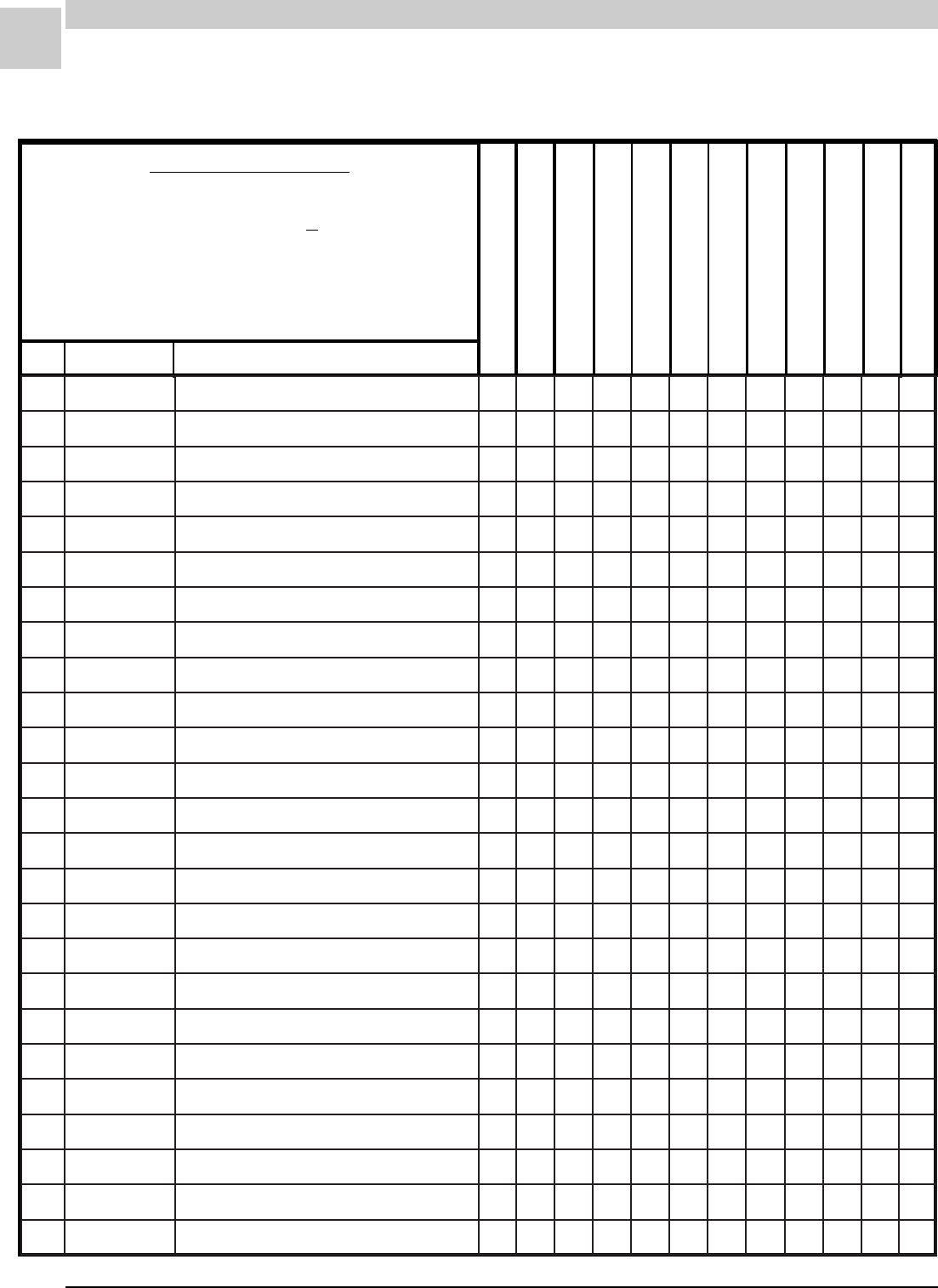
8-40
PARTS LISTS MAGIC-PAK: HW/HWC
SRM-HW/HWC 8/99
HWC3-H-1 REVISED
4-26-99
REC STOCKING PART
TO SELECT PART #
Last letter of the Model # is the Service Level.
64HWC303HA-1A
First find Model #. ------------------------------------------------ >
64HWC303HA-1(*)
Then match Service Level for desired part.---------------- >
SERVICE LEVEL = *
51HWC183HA-1(*)
64HWC183HA-1(*)
38HWC243HA-1(*)
51HWC243HA-1(*)
64HWC243HA-1(*)
51HWC303HA-1(*)
REF PART # PART DESCRIPTION
26HWC123HA-1(*)
38HWC123HA-1(*)
38HWC183HA-1(*)
64HWC303HA-1(*)
1100B07393REMROFSNART +A1111111111
7100-78944LLEWYENOHSAG-EVLAV +A1111111111
11100-47024DLOFINAMA1
11200-47024DLOFINAMA111
11300-47024DLOFINAMA111
11400-47024DLOFINAMA111
31400B03093SAGLARUTAN35#ECIFIROA666
31500B03093SAGLARUTAN45#ECIFIROA445455
31110B03093SAGLARUTAN55#ECIFIROA3
02100-29944EDORTCELE +A1111111111
12100-39944EDORTCELE-ERIW +A1111111111
42100-09944REWOLB/NOITINGI-LORTNOC +A1111111111
43100-84914RENRUBA3445645656
83900D99983REGNAHCXETAEH-YLBMESSAA1
83010D99983REGNAHCXETAEH-YLBMESSAA111
83110D99983REGNAHCXETAEH-YLBMESSAA111
83210D99983REGNAHCXETAEH-YLBMESSAA111
04100B14883SROTALUBRUTA3445645656
64100B77983REVOCEULF-TEKSAG +A1111111111
74100B87983DNE.LOCEULF-TEKSAG +A2222222222
25700B45104TIMIL-LORTNOC +A1111111111
55400B02573DERTUOLLOR-HCTIWS +A 111111111
55500B02573NEERGTUOLLOR-HCTIWS+A1
75010-91844DERERUSSERP-HCTIWS A1111111111
36100-44114TFARDDECUDNI-REWOLB +A1111111111
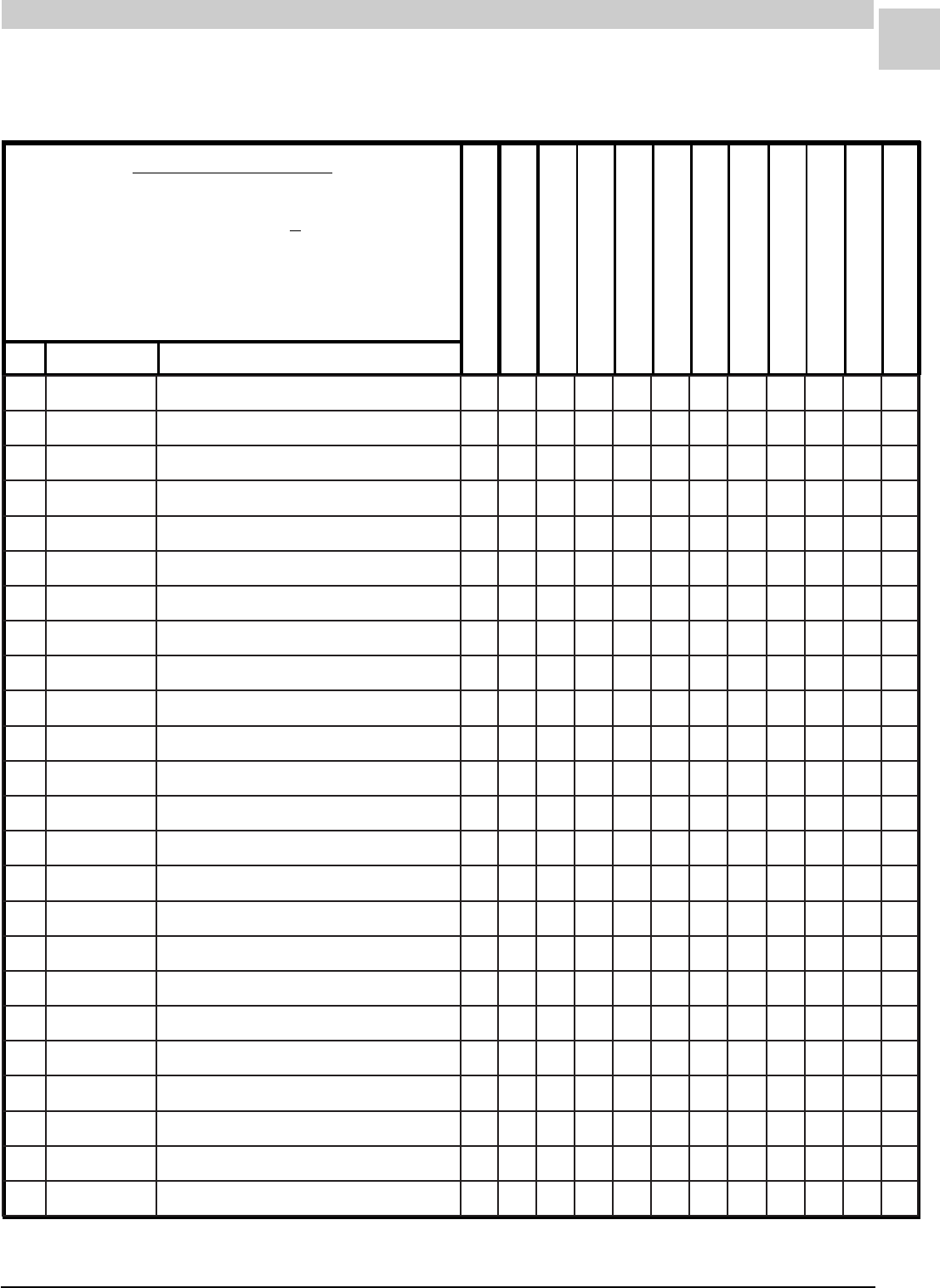
8-41
SRM-HW/HWC 8/99
Service Reference Manual PARTS LISTS
REC STOCKING PART
TO SELECT PART #
Last letter of the Model # is the Service Level.
64HWC303HA-1A
First find Model #. ------------------------------------------------ >
64HWC303HA-1(*)
Then match Service Level for desired part.---------------- >
SERVICE LEVEL = *
51HWC183HA-1(*)
64HWC183HA-1(*)
38HWC243HA-1(*)
51HWC243HA-1(*)
64HWC243HA-1(*)
51HWC303HA-1(*)
REF PART # PART DESCRIPTION
26HWC123HA-1(*)
38HWC123HA-1(*)
38HWC183HA-1(*)
64HWC303HA-1(*)
HWC3-H-1 (cont.) REVISED
4-26-99
96100B54093ESAHP1,PH6/1ROTOM+A11
96100B64093ESAHP1,PH3/1ROTOM +A 11111111
17000B70470GNITNUOMROTOM-DNAB A1111111111
27400B80470GNITNUOMROTOM-MRA A3333333333
37100B33843REWOLB-LEEHW A1111111111
47100B01093SGNISUOHREWOLB-YLBMESSA A1111111111
68100D10043CAV073@DFM4-ROTICAPAC+A11
68400D10043CAV073@DFM5.7-ROTICAPAC +A 11111111
111000B46720LANIMRET-DRAOB +A1111111111
421100-10054REPPUSSENRAHERIW-YLBMESSA A1111111111
521100-20054REWOLSSENRAHERIW-YLBMESSA A1111111111
721640B13160"05.X"52X"5.61RETLIF +A1111111111
031100-40054MARGAIDGNIRIW-LEBAL A1111111111
052100B28983ROODTUO-LIOCA11
052100B38983ROODTUO-LIOCA111
052100-94604ROODTUO-LIOCA11
052100-41114ROODTUO-LIOC A 111
552100B97983ROODNI-LIOCA11
552100B08983ROODNI-LIOC A 111111
552100-84604ROODNI-LIOCA11
652100-17234SREIRD-RETLIF/WEBUT.PAC-YSSAA11
652200-17234SREIRD-RETLIF/WEBUT.PAC-YSSA A 111
652300-17234SREIRD-RETLIF/WEBUT.PAC-YSSAA111
652100-57334SREIRD-RETLIF/WEBUT.PAC-YSSAA11
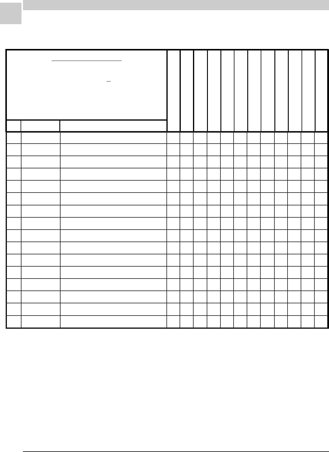
8-42
PARTS LISTS MAGIC-PAK: HW/HWC
SRM-HW/HWC 8/99
REC STOCKING PART
TO SELECT PART #
Last letter of the Model # is the Service Level.
64HWC303HA-1A
First find Model #. ------------------------------------------------ >
64HWC303HA-1(*)
Then match Service Level for desired part.---------------- >
SERVICE LEVEL = *
51HWC183HA-1(*)
64HWC183HA-1(*)
38HWC243HA-1(*)
51HWC243HA-1(*)
64HWC243HA-1(*)
51HWC303HA-1(*)
REF PART # PART DESCRIPTION
26HWC123HA-1(*)
38HWC123HA-1(*)
38HWC183HA-1(*)
64HWC303HA-1(*)
HWC3-H-1 (cont.) REVISED
4-26-99
262900C521534A-980-TE105WA-ROSSERPMOC A 111
262100C800934A-200-TE741KR-ROSSERPMOCA11
262500-11824031-VFP-CK42RZ-ROSSERPMOCA111
262600-11824031-VFP-CK82RZ-ROSSERPMOCA11
762100-45214ESAHP1,PH4/1ROTOM +A 11111
762100-28214ESAHP1,PH8/1ROTOM +A11111
862100B26093NAF-EDALB A 11111
862100B58093NAF-EDALB A11111
962400D28930TROPPUSROTOM-TEKCARB A1111111111
172200D41583CAV073@DFM5/52-ROTICAPAC+A11
172400D41583CAV073@DFM5/53-ROTICAPAC +A 11111111
672100-52724ROSSERPMOC-GULP +A 11111
872100C53570ROTCATNOC +A1111111111
103100B95093REIRD-RETLIF+A11
103200B95093REIRD-RETLIF +A 111111
103300B95093REIRD-RETLIF+A 11

Service Reference Manual TROUBLESHOOTING
9-1
SRM-HW/HWC 8/99
Section 9 - Troubleshooting/
Performance/
Charge Weights
Troubleshooting ................................... 9-2
Compressor Checkout ................................ 9-2
Capacitor Checkout .................................... 9-6
Performance ........................................ 9-9
Performance Tests (Installed)...................... 9-9
Performance Tests (Bench Tested) ............. 9-11
Charge Weights ................................. 9-11

9-2
TROUBLESHOOTING Magic-Pak: HW/HWC
SRM-HW/HWC 8/99
Troubleshooting
Compressor Checkout
The objective of this section is to help in diagnosing compressor prob-
lems. It presents a series of tests that should be conducting before a
determination on the condition of the compressor is made. This section
has been organized so that the simplest checks are done first, followed by
the more detailed tests (if necessary).
Initial Testing
If a compressor failure is suspected, several simple checks should be
done initially to make sure that the right course of action is being taken.
The following is a list of items and points that should be looked at before a
determination is made of the condition of the compressor.
•Is the correct voltage available at the unit? Using a volt/ohm meter,
check the voltage and compare with the voltage specified by the
manufacturer (found on the data plate on the unit). Many compres-
sors are replaced only to find later that there was either no power or
incorrect power available to the unit.
•Is the contactor closing? Check to make sure that there is 24 volts at
the coil side of the contactor. Check to make sure the points in the
contactor are in good condition. Are they pitted or corroded to the
point where they no longer conduct electricity?
•Is the capacitor in good condition? Does it have the correct rating for
the application? Using a meter, determine if it still has the correct
capacitance.
•The last of these initial tests to do is a touch test. This should be
done very carefully as the compressor can become very hot in
certain situations. This information may be helpful if further tests are
needed to determine the condition of the compressor.
Further Testing
Use extreme caution when conducting the following tests. The power
must be turned off before continuing with the testing.
Checking Continuity
1. Remove wires from the fusite plug in the compressor, recording the
location of each wire as it is removed. If a wire is misplaced when the
test is complete, serious damage could be done to the compressor.
Use extreme caution when performing maintenance or
troubleshooting operations. Electrical shock could
cause personal injury or death.
WARNING

Service Reference Manual TROUBLESHOOTING
9-3
SRM-HW/HWC 8/99
2. Set an ohm meter to the lowest possible setting. On a note pad,
write the following: “C to ground”, “S to ground” and “R to ground.”
3. Using the ohm meter, check for continuity between C terminal on the
fusite plug and the case of the compressor (a spot may have to be
cleaned on the compressor to get a good reading.) Record what was
observed on the note pad next to the heading “C to ground”. Do the
same to the other two terminals and record the findings in the proper
places.
4. If any sign of continuity between any of the terminals and ground was
observed, recheck the terminal to confirm that the readings were
correct. Any indication of continuity between any of the terminals and
ground would point to an internal winding being shorted to the
compressor case. This suggests that the compressor has an internal
failure and it would need to be replaced.
5. If no continuity is noted between any of the terminals and ground, the
compressor must be checked out further.
Checking Windings
The following test is used to check the condition of the internal start and
run windings.
1. Write the following down: “C to S”, “C to R” and “S to R.”
2. Using the volt/ohmmeter, measure the resistance between terminals
C and S. Record the findings on the note pad in the correct place.
Measure and record the resistance between the remaining terminals
in the same manner.
The following examples show how this information can be used to deter-
mine if there is an internal failure.
Example #1
C to S (Common through Start Windings) 3.5 ohms
C to R (Common through Run Windings) 1.5 ohms
S to R (Start Windings through Common and Run Windings) 5.0 ohms
A resistance measurement between C to S shows that there is continuity
between the common and start terminals. The reading between terminals
C and R proves that there is continuity between the terminals through the
windings. The resistance recorded between S and R is actually a reading
of the entire circuit within the motor (S through C to R).
A determination of the condition of the motor windings can be made with
the information just collected. The following steps show how this is done.
1. Add the readings from “C to S” and “C to R.”
C to S (3.5 ohms) + C to R (1.5 ohms) = 5 ohms

9-4
TROUBLESHOOTING Magic-Pak: HW/HWC
SRM-HW/HWC 8/99
When the resistance of “C to S” is added to the resistance of “C to R”,
the combination is the total resistance of the entire motor windings
circuit.
2. Compare the total to the reading taken between “S to R.” If the
windings are in good condition, the sum of “C to S” and “C to R”
should be the same as the reading between “S to R” (S through C to
R). (In this example, they are equal.)
If the numbers are the same, this suggests that the windings are intact
and that there are no internal shorts between the start and run windings.
Example #2
In the following example, the measurements taken provide different
results from the earlier example. These results would indicate that there
is a problem with the compressor.
C to S (Common through Start Windings) 3.5 ohms
C to R (Common through Run Windings) 1.5 ohms
S to R (Start Windings through Common and Run Windings) 4.3 ohms
Using the procedure followed in Example #1:
C to S (3.5 ohms) + C to R (1.5 ohms) = 5 ohms
In this example, the actual reading of “S to R” is 4.3 ohms. In comparing
the readings taken, the resistance measured between “S to R” (the
resistance of the entire motor windings circuit) is not equal to the sum of
“C to S” and “C to R.”
A short between the windings of the start and run coils would reduce the
length of the wire being measured and would result in less resistance
between the two points. Instead of measuring the resistance from “S to C
to R”, the resistance is actually being measured through an internal short
in the windings to the R terminal, bypassing the C terminal. This results
in a lower resistance reading and indicates that the compressor has failed
and the windings are shorted.
Checking the Thermal Overload Device
If during the time that resistance was being checked in the previous test
infinity was ever registered (meter indicated no continuity), the assump-
tion could be made that there is an open winding (or a break in the wires
of the winding). This may indicate that the windings had burned out and
that the compressor had failed.
In the motor windings there is a thermal overload device. This device is
designed to open if the internal temperature of the windings exceed a
preset limit. Since the resistance reading of a winding where the thermal
overload device has opened would show no resistance, the assumption
would most likely be made that the winding was burned out. This is
where the temperature of the compressor as noted in the touch test
becomes very important. If at the time of the touch test the compressor
was found to be very hot, then there is a good chance that the thermal

Service Reference Manual TROUBLESHOOTING
9-5
SRM-HW/HWC 8/99
overload protector has opened. Before the compressor can be con-
demned as having a burned out start or run winding, it must be deter-
mined that the overload switch is in fact closed. It may take several hours
for the compressor to cool down enough to guarantee that the switch has
closed. After enough time has elapsed for the switch to close, the resis-
tance between each of the terminals should be measured. It may be
found that with the overload switch closed, the compressor checks out
electrically sound. If this is the case, then other possibilities have to be
looked at as to what caused the compressor to overheat.*
There are several reasons why a compressor would overheat.
• If the capacitor was incorrect or failing, the amp draw (current flow)
would be increased. This could cause the motor to heat up very
rapidly, activating the thermal overload protection device. This would
interrupt power and protect the motor windings from damage.
• A loss of charge could also cause the operating temperature of the
compressor to rise and open the thermal overload switch.
• Restricted airflow through the coil could also cause the operating
temperature of the unit to rise.
It is important to perform these checks before making a decision as to the
condition of the compressor.
* An open thermal overload device in a motor does not mean that the
motor was damaged or harmed in any way.

9-6
TROUBLESHOOTING Magic-Pak: HW/HWC
SRM-HW/HWC 8/99
Capacitor Checkout
Before starting the checkout of the capacitor, it is important to understand
what a capacitor is, how it works and what its function is in relation to a
motor.
A capacitor is a storage device similar to a battery, only unlike a battery
a capacitor wants to give up its energy all at once. This ability to store and
release energy is used to make motors run more efficiently, with more
power in a smaller size and to start easier. There are many types of
capacitors but they all serve one common purpose, to store electrons.
Capacitance refers to the capacitor’s ability to store electrons. Different
size capacitors hold different amounts of charge.
Capacitance is measured in farads. A 1-farad capacitor connected to a
1-volt power supply will store 6,280,000,000,000,000,000, or (6.28 x 10 to
the 18th power) electrons. Most capacitors store a much smaller quantity
of electrons. Smaller capacitors have different terms to indicate the
quantity of electrons that they can store. A picofarad is one trillionth of a
farad; a microfarad is one millionth of a farad. The microfarad is the
term most often used in the HVAC business, this is marked on a capacitor
as “MFD”.
The capacitor that is most often used in the HVAC business is known as
an electrolytic capacitor. The electrolytic capacitor is unique in that a
thin layer of oxide is formed on the aluminum sheets used to make up its
internal parts. The electrons that are supplied to the capacitor are stored
in this layer of oxide. But by doing this, nature is being forced to do
something that it doesn’t want to do. Nature likes to be in equilibrium. The
fact that nature prefers to return to a steady state is the idea behind the
use of capacitors. By storing a fixed amount of energy in the capacitor, it
provides the reserve of extra power needed to start and run a motor.
Without this energy source, motors would have to be much bigger and
more complex.
A capacitor can store a charge for a considerable
length of time after the power has been turned off.
This charge can be very dangerous. An electrolytic
capacitor charged with only 10 or 15 volts can melt
the tip of the end of a screwdriver when placed
across the terminals. A high voltage capacitor can
store a charge that could be lethal. Never touch the
terminals of a capacitor without first discharging it.
WARNING
Capacitor Testing
Capacitors are an integral part of the system and must be checked along
with the motor when a problem occurs.
Check to make sure that the capacitor is correctly rated for the applica-
tion. Confirm that the right capacitor is being used for the application.

Service Reference Manual TROUBLESHOOTING
9-7
SRM-HW/HWC 8/99
The following information is found on a capacitor: the MFD (microfarad
rating) and the working voltage. Compare this to the rating plate on the
motor or the information provided with the unit.
The following are some of the problems that could be caused by a
defective or incorrect capacitor:
• Motor overheating (internal thermal overload tripped)
• Motor refuses to start
• Intermittent problems with blown fuses or breaker tripped
• High electrical consumption
• Motor rotates in the wrong direction
• Contactor overheating or melted contacts
• Motor vibration
Any one of the above faults could be attributed to the capacitor. There-
fore, the capacitor must be checked out before a determination is made of
the problem.
In the past, the old method of swinging the meter needle to tell if the
capacitor was good or not could be used. When the terminal of the
capacitor was touched with the meter probes, the meter needle would
swing over than back to zero. If it didn’t, it could be assumed that the
capacitor had failed. There are many problems with this technique.
Swinging the meter needle only proves that the capacitor will take a
charge, but not how much of a charge. In some cases, when a capacitor
starts to break down it still will take a charge (but the number of electrons
that it can hold is greatly reduced). The capacitor must take the correct
charge as originally designed so that the motor will work as it should. A
much more accurate method must be used to determine the condition of
the capacitor before the decision on its condition can be made.
The best method is to use a meter that is capable of reading capacitance.
This gives a very accurate indication of the condition of the capacitor. If a
meter that is able to do this is not available, then another way to deter-
mine the condition of the capacitor must be found.
In order to do this, several things will be needed: a volt ohm meter, an
amp meter and a calculator. A set of test leads will also need to prepared
to do this test. Make the test leads with a loop (10 loops) in one of the
leads. The ten loops in the lead will cause the amp meter reading to be
multiplied by “ten”. This will make it much easier to read very low amp
meter readings and will be helpful when doing the following test.
Connect the alligator clips of the test leads to the terminals on the capaci-
tor. Hook the amp meter through the 10 loops of wire on the test lead
(see Figure 9-1 on page 9-8).

9-8
TROUBLESHOOTING Magic-Pak: HW/HWC
SRM-HW/HWC 8/99
Before starting the test, take a reading of the line voltage at the outlet that
will be used.
Double check the connections, making sure that the amp meter is on.
Plug the test leads into the wall outlet. Wait a few seconds and read the
amp meter (CAUTION: there is only approximately ten seconds to do this
or the capacitor could be damaged). Unplug the jumper and record the
readings.
Using the calculator, divide the amp meter reading by ten (the number of
loops in one of the test leads). This is the correct amp reading which is
needed to finish the calculations. This information and the voltage at the
outlet is all that is needed to calculate the capacitance of the capacitor.
Nominal
Voltage
Source
Fuse
(10 Loops)
Voltmeter Capacitor
To Be Tested
V
A
Ammeter
FIGURE 9-1 Determining Capacitance (MFD) Rating with a Test
Cord
Example
This calculation provides the actual capacitance of the capacitor. Com-
pare this reading to the listed rating on the capacitor. It should be within
+/– 10% of the actual capacitor rating. If it does not fall within this range,
the capacitor is defective and should be replaced.
The capacitor should always be checked before replacing an electric
motor. Eliminate the capacitor as a possible cause of the problems
before the decision is made to replace the motor. A good practice is also
to replace the capacitor whenever a motor is replaced, as the capacitor
does have a service life cycle. The capacitor is a very important part of
the motor electrical system. Always check the capacitor along with the
motor when a fault is noted.
*For 50 Hz electrical systems, use 3180 as the constant multiplier.
2650 x 1 Amp
115 Volts = 23 MFD
2650 x Amps
Volts = Capacitance (MFD)
In the following calculation, a constant multiplier (2650) is used for 60 Hz
electrical systems.*
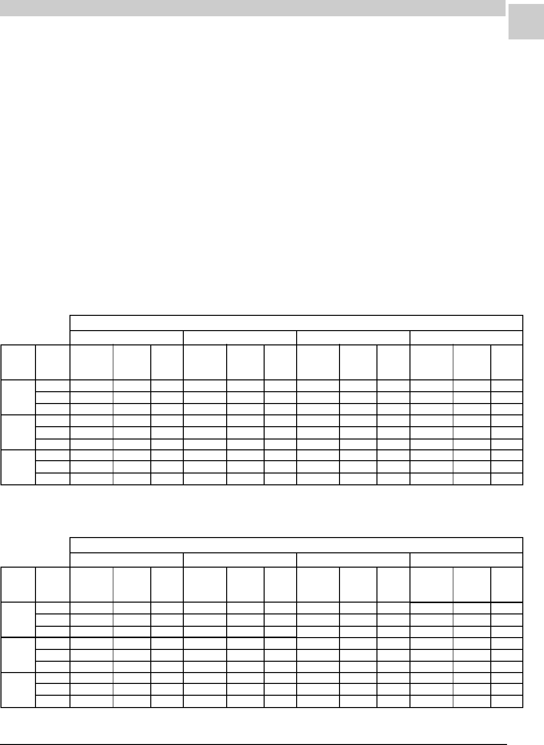
Service Reference Manual TROUBLESHOOTING
9-9
SRM-HW/HWC 8/99
Performance
Performance Checkout
HW/HWC chassis come with a pre-charged chassis assembly. The
chassis assembly is designed in a way that the unit may be run indepen-
dently of the HWC unit. When the chassis is run on a floor or bench, the
performance measurements will be affected due to the change in static
pressures, recirculated air, excessive temperatures and equal ambient
temperatures from indoor to outdoor.
Two sets of tables are provided in this section to address these issues.
Tables 9-1 to 9-4 are to be used when the chassis is still installed in the
complete unit. Tables 9-5 and 9-6 are to be used when the chassis is run
independently outside of the unit.
Note: Pressures may vary +/– 10 psi. Temperatures may vary =/– 2-3°F.
Performance Tests (Chassis Installed in Unit)
Total
Air Vol.
(CFM)
Enter.
DB/WB
Suction
Pressure
Suction
Tem p.
Liquid
Tem p.
Suction
Pressure
Suction
Te m p .
Liquid
Te m p .
Suction
Pressure
Suction
Te m p .
Liquid
Te m p .
Suction
Pressure
Suction
Tem p.
Liquid
Tem p.
Outdoor Air Temperature Entering Outdoor Coil
85° 95° 105° 115°
400
450
500
400
450
500
400
450
500
75°/63°
80°/67°
85°/71°
81 49 87 82 49 97 84 50 107 85 51 117
83 54 87 84 50 97 86 51 107 87 52 117
85 60 87 86 52 97 88 52 107 89 53 117
87 63 87 88 53 97 89 53 107 91 54 117
88 68 88 90 58 97 91 54 107 93 55 117
90 73 88 92 63 97 93 57 107 95 56 117
92 74 88 93 64 97 94 56 108 96 57 117
94 79 88 95 71 97 96 62 108 98 58 117
96 84 88 97 74 97 98 65 108 100 59 117
Based on a normally installed cooling chassis
TABLE 9-1 HWC122 Performance Test (Chassis Installed)
Total
Air Vol.
(CFM)
Enter.
DB/WB
Suction
Pressure
Suction
Tem p.
Liquid
Tem p.
Suction
Pressure
Suction
Te m p .
Liquid
Te m p .
Suction
Pressure
Suction
Te m p .
Liquid
Te m p .
Suction
Pressure
Suction
Tem p.
Liquid
Tem p.
Outdoor Air Temperature Entering Outdoor Coil
85° 95° 105° 115°
550
600
650
550
600
650
550
600
650
75°/63°
80°/67°
85°/71°
80 49 96 81 48 106 84 50 114 86 51 123
82 54 96 83 50 106 86 51 114 88 52 123
84 59 96 85 52 106 88 52 114 90 54 124
86 62 98 88 53 106 90 54 115 92 55 124
87 67 98 89 58 107 91 54 116 94 56 125
99 72 98 91 62 107 93 57 116 95 56 125
91 73 99 93 64 107 95 56 116 97 58 125
93 78 99 95 70 108 97 63 117 99 59 126
95 83 99 97 74 108 99 66 117 101 60 126
Based on a normally installed cooling chassis
TABLE 9-2 HWC182 Performance Test (Chassis Installed)
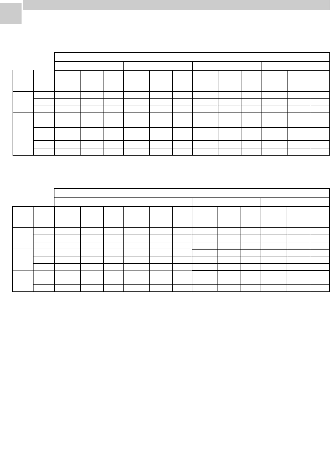
9-10
TROUBLESHOOTING Magic-Pak: HW/HWC
SRM-HW/HWC 8/99
Performance Tests (Chassis Installed in Unit) - cont.
Total
Air Vol.
(CFM)
Enter.
DB/WB
Suction
Pressure
Suction
Tem p.
Liquid
Tem p.
Suction
Pressure
Suction
Tem p.
Liquid
Tem p.
Suction
Pressure
Suction
Te m p .
Liquid
Te m p .
Suction
Pressure
Suction
Te m p .
Liquid
Tem p.
Outdoor Air Temperature Entering Outdoor Coil
85° 95° 105° 115°
775
850
925
775
850
925
775
850
925
75°/63°
80°/67°
85°/71°
76 46 100 77 46 110 78 46 120 79 47 129
78 51 100 79 47 110 80 48 120 81 48 129
80 57 100 81 49 111 82 49 120 83 50 130
82 60 102 84 51 111 85 51 121 87 52 131
84 65 102 85 56 112 87 52 121 88 53 131
85 70 102 87 60 112 88 54 121 89 53 131
89 72 103 90 63 112 92 55 122 93 55 132
91 77 104 92 69 113 94 61 123 95 57 133
93 82 104 94 72 113 96 64 123 97 58 133
Based on a normally installed cooling chassis
TABLE 9-4 HWC302 Performance Test (Chassis Installed)
Total
Air Vol.
(CFM)
Enter.
DB/WB
Suction
Pressure
Suction
Tem p.
Liquid
Tem p.
Suction
Pressure
Suction
Tem p.
Liquid
Tem p.
Suction
Pressure
Suction
Tem p.
Liquid
Tem p.
Suction
Pressure
Suction
Te m p .
Liquid
Te m p .
Outdoor Air Temperature Entering Outdoor Coil
85° 95° 105° 115°
700
800
900
700
800
900
700
800
900
75°/63°
80°/67°
85°/71°
77 47 98 78 46 108 79 47 117 80 48 128
79 52 98 80 47 108 81 48 117 82 49 128
81 57 99 82 50 109 83 49 118 84 50 128
82 60 99 83 51 109 85 50 118 86 51 128
84 65 100 85 56 109 87 52 119 88 52 129
86 70 100 87 60 110 89 55 119 90 53 129
87 71 100 88 61 110 89 53 119 90 54 129
89 76 101 90 68 110 91 59 120 92 55 130
91 81 101 92 71 110 93 62 120 94 56 130
Based on a normally installed cooling chassis
TABLE 9-3 HWC242 Performance Test (Chassis Installed)
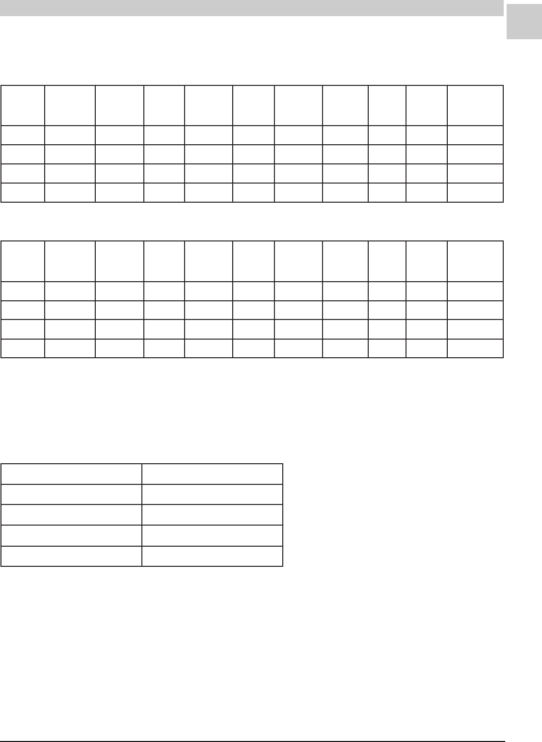
Service Reference Manual TROUBLESHOOTING
9-11
SRM-HW/HWC 8/99
Performance Tests (Chassis Bench Tested)
TABLE 9-6 95° Ambient Temperature Chassis Bench Test
TABLE 9-5 70 - 80° Ambient Temperature Chassis Bench Test
sissahC
ledoM
tneibmA
.pmeT
BW/BD
.hcsiD
erusserP
.hcsiD
.pmeT
diuqiL
erusserP
diuqiL
.pmeT
noitcuS
erusserP
noitcuS
.pmeT
latoT
spmA
.pmoC
HS gniloocbuS
321,221°36/°57isp571°021isp071°87isp87°350.57 31
381,281°36/°57isp002°701isp091°08isp28°453.85 81
342,242°36/°57isp502°99isp002°18isp17°057.018 12
303,203°36/°57isp502°351isp002°48isp07°265.311281
sissahC
ledoM
tneibmA
.pmeT
BW/BD
.hcsiD
erusserP
.hcsiD
.pmeT
diuqiL
erusserP
diuqiL
.pmeT
noitcuS
erusserP
noitcuS
.pmeT
latoT
spmA
.pmoC
HS gniloocbuS
321,221°97/°59isp072°451isp072°99isp011°380.68152
381,281°97/°59isp013°141isp503°601isp011°862.013 52
342,242°97/°59isp523°351isp013°411isp101°962.419 91
303,203°97/°59isp503°771isp003°501isp88°684.612352
Charge Weights
TABLE 9-7 HWC Refrigerant Charge Weights
ledoMegrahCtnaregirfeR
321/221CWH.zo24
381/281CWH.zo65
342/242CWH.zo85
303/203CWH.zo95
