Array Solutions Array Solutions OM4000HF External Power Amplifier User Manual Exhibit6 OM4000HF

Array Solutions dba Array Solutions External Power Amplifier Exhibit6 
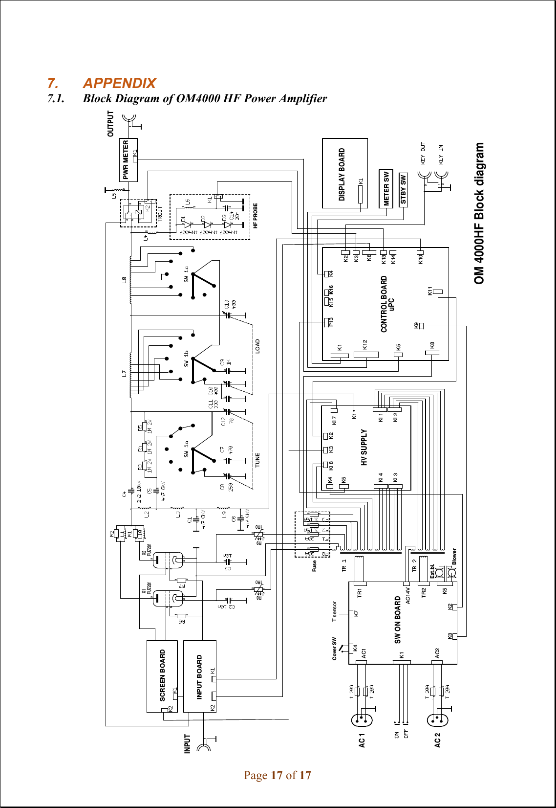
OM4000HF

User Manual

Exhibit 6: User’s Manual External Radio Frequency Power Amplifier OM4000HF Model 4000HF Array Solutions 2611 North Beltline Rd  Suite 109 Sunnyvale, Texas 75182 USA Tel: 214 954 7140 fax: 214 954 7142 E-mail: info@arraysolutions.com
Page 2 of 17 TABLE OF CONTENTS 1. GENERAL INFORMATION1.1.     Introduction   ………………………………………………………………..      4 1.2.     Specification   ……………………………………………………………....    4 1.2.1. Parameters   ………………………………………………………………….     4 1.2.2. Protection Circuits   …………………………………………………………      4 1.2.3. Indicators   …………………………………………………………………..      5 2. SAFETY INSTRUCTIONS   ………………………………………………     53. GENERAL DESCRIPTION ……………………………………………….     63.1.      HF part   …………………………………………………………………….     6 3.2.      Power Supply    ……………………………………………………………..     7 3.3.      Safety Devices   …………………………………………………………….     8 4. INSTALLATION   …………………………………………………………     84.1.      Grounding   …………………………………………………………………     8 4.2.      Coaxial Cable   ………………………………………………………….......     8 4.3.      Control Cable   ………………………………………………….…………...    9 4.4.      Mains Supply   ………………………………………………………………    10 4.5.      Cooling   …………………………………………………………………….    10 5. OPERATION   ………………………………………………………………   105.1.      Operation Elements   ………………………………………………………..    11 5.2.     Tuning of Power Amplifier      ……………………………………………..      12 6. MAINTENANCE     ……………………………………………………….     156.1.      Indication of Fault Conditions     ………………………………………….      15 6.2.      Fuse Replacement      . .…………………………………………………....      16 6.3.      Tube Replacement     ………………………………………………….......      16 6.4.      Cleaning     ……………………………………………………………......       16
Page 3 of 17 7. APPENDIX    ……………………………………………………………...      177.1.      Block Diagram of OM4000 HF Power Amplifier   ……………...………...     17
Page 4 of 17 1. GENERAL INFORMATION1.1.    Introduction The OM Power model OM4000 HF is a manual tuning power amplifier, designed for use on all short wave amateur bands from 1.8 to 29.7 MHz (including WARC bands) and all modes. . It is equipped with a two pieces of ceramic tetrode FU728F.  1.2. Specification 1.2.1. Parameters Frequency Coverage  Amateur Bands 1.8 – 29.7 MHz including WARC Power Output   1500W PEP continuous output – no time limit  Input Power    Usually 50 to 70W for full Output Power Input power can not exceed 100W !  Input Impedance  50 Ohm, VSWR < 1.5 : 1 Power Gain    15 dB Output Impedance    50 Ohm unbalanced Maximum Output SWR  2 : 1 SWR protection  Automatic switching to STBY, when reflected power is 350W or higher Intermodulation distortion  31dB below nominal output Suppression of harmonics  < -50 dBc Tubes    2x FU728F Ceramic tetrode Cooler   Centrifugal blower + Axial blower Power supply    240V – 60Hz Transformers    2 pcs of toroidal transformer 3kVA Dimensions    485x200x455mm (width x height x depth) (19”x8”x18”) Weight   43 kg (94.8 lbs) 1.2.2. Protection Circuits There are 11 special protection circuits used in the amplifier. They are activated when one or more of next parameters exceed defined values or some unwanted occasion occurs. •VSWR too high•Input power too high•Output power too high•Plate voltage too low•Anode current too high•Screen current too high•Grid current too high•Mistuning of PA•Hot switching protection•Soft start for protecting your fuses•“switch-on blocking “ at opened amplifier
Page 5 of 17 1.2.3. Indicators There are couples of LED and bar graph indicators visible on the front panel to inform you about value of some parameters or operation status: Bar graph indicators  Power output -  50 LED Reflected power – 20 LED Current at screen Ig2 – 10 LED Anode voltage, anode current, tuning – 30 LED LED Indicators  Current at control grid (Ig1 – 2 LED) WAIT – preheating of tube (180 sec) STBY – standby OPR – operation condition FAULT – failure, switching off for abt. 2 sec 2. SAFETY   INSTRUCTIONSWARNING! DANGEROUS HIGH VOLTAGE! The power amplifier is using high voltage up to 3400V DC, which is very dangerous for human life! Read next safety instructions carefully first, before you will start to install and operate power amplifier!    NEVER VIOLATE NEXT RULES! WARNING!        NEVER  ALLOW  CHILDREN  to  play  around  PA  or  to  touch  power amplifier  or  connected  cables  in  working  condition,  or  to  push  anything  into  the  case holes! WARNING!  The amplifier contains high voltage circuits. Never turn the amplifier on without the upper lid in place.  DO NOT  ATTEMPT  TO SHORT OR BYPASS safety switch under upper lid! WARNING!      The  OM4000  HF  amplifier  is  neither  to  be  used  in  a  WET  or  HUMID environment nor to be exposed to RAINFALL! WARNING!  Do not turn the amplifier on without having connected the ANTENNA or properly rated DUMMY LOAD! A hazardous HF voltage may build up on the antenna connector after turning the amplifier on with no antenna or dummy load connected!
Page 6 of 17 WARNING!  Before opening the upper lid of the amplifier make sure that power supply has  been  disconnected  AT  LEAST  5  minutes,  allowing  the  electrolytic  capacitors  to discharge fully. Disconnect power cord from the outlet!  WARNING!  OM4000 HF amplifier can be operated ONLY if both of supply cables are connected!   WARNING!  Make sure that all screws holding the case together are properly in place and tightened before carrying the amplifier with the handles! CAUTION!  The amplifier must be installed in such a way that free flow of hot air from the  tube  is  allowed.  The  amplifier  must  not  be  installed  in  a constrained  surrounding (i.e. tight shelves etc.). During long operation the upper lid and the vent grid can reach high temperature! CAUTION! The amplifier must be properly grounded during operation. CAUTION!    During  operation  the  amplifier  must  be  installed  in such  a way  that  the back of the amplifier remains accessible. CAUTION!  The  amplifier  is  an  A category  product.  In  a household  it  can  influence other electric appliances. In such cases the user is responsible to take proper actions to mitigate this disturbance. CAUTION!  Read  this  manual  carefully.  Fallow  all  of  instructions  during  installation and  operation  to  avoid  damage  to  the  amplifier  not  covered  by  manufacturer´s warranty!  Do not attempt to perform any change of hardware or software!  3. GENERAL DESCRIPTION3.1.  HF part his  amplifier  is  using two  pieces  of  ceramic  tetrode  FU728F in  a  grounded-cathode circuit  (input  into  control  grids).  OM4000  HF  achieves  excellent  linearity  by  the voltage stabilization of the control grid bias and the screen voltage. The power input is given to the control grid, using a broadband input circuit with an input impedance of 50 Ohms.  This  adaptable  input  circuitry  ensures  a  good  input  SWR  (better than  1.5:1)  on  all amateur bands. The output of the amplifier is a Pi-L circuit. The ceramic capacitor for TUNE and LOAD are divided. This enables the amplifier to be tuned exactly and makes it possible to easily return to the previously set positions after band changes. T WARNING! The installation of this device must be compliant with CFR 47, 1.1310 of the Federal Communications Commission rules. Refer to guidance in OET Bulletin 65, Supplement B for more information on evaluation of the installation.
Page 7 of 17 Top view on the opened OM4000 HF       Tetrode FU728F            PWR meter            Blower            Switch-on board     Output Pi-L Circuit   Tuning capacitor             Power supply board   Subpanel 3.2. Power Supply Power supply of the amplifier is comprised of two of 3 kVA toroidal transformers. A soft start is provided using relays and resistors. The high anode voltage is made by combining 8 x 420 V (total 3360V) @ 2.5A. Each has its own rectifier and filter. In the high voltage circuit, safety resistors are employed to protect the amplifier against overload.  The source for screen grid is regulated by parallel stabilization and delivers a voltage of 350V at 200mA. The -120V for the control grid is regulated with Zener diodes.
Page 8 of 17 3.3. Safety Devices Control  and  monitoring  circuits  ensure  control  and  safety  during  malfunctions  of  the  PA. These are on the Control board, which is located on the chassis subpanel. 4. INSTALLATIONNOTE Read this chapter carefully prior you will start installation. Before unpacking inspect shipping woody  container  first,  if  it  is  not  damaged.  Keep  all  of  packing  parts  for  possible  future shipment. Check unpacked power amplifier. If you find some damaging, contact your dealer immediately to keep full warranty. During installation go step by step according to next  parts. 4.1.    Grounding CAUTION The amplifier has to be grounded properly! Connect the screw on the rear panel of the amplifier to your local  grounding system with a  copper  cable, use a cross-section  of  4 mm2 at least.  Connect your transceiver to the same grounding system of your shack carefully! Use minimum length cables and make certain that the connections are both physically and electrically sound. With poor grounding, you may risk damaging your equipment, having problems with TVI/BCI or your transmitted signal may be distorted. 4.2.     Coaxial Cable The  output  of  the  transceiver  is  to  be  connected  to  the  input  of  the  amplifier  via  RG58  or similar  cable.  For  the  connection  between  the  power  amplifier  and  the  antenna,    RG213  or similar coaxial cable suited for high power is recommended. Both the INPUT and OUTPUT SO-239 sockets with Teflon insulation is used.
Page 9 of 17 Rear view of the amplifier OM4000 HF AC SOCKETS FUSES    OUTPUT  CONTROL  INPUT  4.3.     Control Cable Control cable maintains TX / RX switching of the PA  (TX GND). The cable is shielded. On the side of the power amplifier a CINCH-socket is used. On the side of your transceiver you have  to  use  a  socket  suitable  for  this  transceiver.  During  transmitting  the  middle  pin  is connected to the ground. The relays of the OM4000 HF have to be switched earlier than HF is applied (cold switching). Modern transceivers they have a time delay between PTT switching and power output. CAUTION If  you  are  using  and  older  transceiver  or  transmitters  without  time  delay,  we recommend to connect the PA in such a way that the transmit/receive switch (foot switch for  example)  is  connected  with  the  KEY  IN  socket  of  the  amplifier.  The  KEY  OUT socket is to be connected with the PTT socket at the transceiver. The amplifier is equipped with two safety devices, which ensure that the output relay is not switched under power mistakenly (hot switching). KEY IN  RCA Phono - Input signal PTT  switching voltage / current   5V /2 mA) KEY OUT  RCA Phono - Output signal PTT (maximum switching of  30V / 50mA)
Page 10 of 17 4.4.     Mains  Supply CAUTION Be  sure  you  got  PA  with  properly  terminated  mains  cables,  corresponding  with  your power system’s outlet. If  not, contact your dealer. In  such a case you  should make the necessary changes using a licensed electrician. WARNING! Be  sure  that  your  power  system  is  correctly  wired  and  properly  rated!  To  use adequately sized and connected grounding system is also very important. 4.5.     Cooling CAUTION The amplifier must be installed in such a way that free flow of hot air from the tube is allowed. Do not obstruct air intake and exhaust areas of the PA. The  centrifugal  blowers  provide  the  necessary  cooling  of  the  amplifier,  even  during  long contests.  The  main  blower  is  activated  by  switching  the  PA  on  and  it  is  turned  off  when cooling is finished (approx. 1-5 min after switching off the PA depending on the temperature of the tube). The supplemental fan is turned on depending on the temperature of the air exiting from the amplifier. It is switched on at 158°F and switched off at 140°F.  5. OPERATIONWARNING! Before switching PA on, make sure that amplifier is grounded, antenna or dummy load is connected, and line cord is putted to the outlet. CAUTION Before switching PA on, check all connections between PA and TCVR.
Page 11 of 17  CAUTION Do not turn PA on for at least 2 hours after unpacking it and locating in its operating location. Especially when amplifier is moved from a  cold place to a warm one because not  visible  condensation  may  develop,  and  this  could  result  in  damage  to  the  high voltage circuits of the PA.   CAUTION Never try to change antenna output during a transmission to avoid warranty loss.  NOTE When  you  decide  to  have  a  short  operating  break,  place  the  amplifier  in  the  standby  mode rather than switch it off.     5.1.     Operation Elements  There is couple of operational elements accessible or visible on the front panel.     BAND-  Band selector switch  (not in the picture).  TUNE -   Anode capacitor for tuning, tuning of higher frequencies to "0", lower frequencies to „100“.  LOAD -          Output capacitor tunes antenna load resistance to amplifier.                          Capacity is low at „100“ and high at "0" on the scale.  OFF -             You switch off the amplifier by pressing this button.  ON -             You switch on the amplifier by pressing this button.                        After 3min of warm-up delay, the amplifier will be ready for operation.  OPR/STBY      „OPERATE“  sets the amplifier ready for transmit operation.
Page 12 of 17  In  STBY,  if  WAIT-LED  is  on  or  the  amplifier  is  OFF,  the  amplifier                 is  in  bypass-mode  and  your  transceiver  is  directly  connected  to  the     antenna. Maximum allowed  power in bypass mode is 200 Watts!                             RF OUTPUT   Bar graph – shows output power .  REFLECTED POWER           Bar graph –  shows reflected power from the antenna.              Maximum  level  is  350W  otherwise  amplifier  switches  to             STANDBY mode.  Ig2  Bar  graph  –  measures  the  current  of  the  second  grid  from  -80mA  to +120mA.  HV/IP/TUNE           Bar graph – measure the anode voltage, anode currency or tuning of  PA.    5.2. Tuning of Power Amplifier  The OM4000 HF amplifier is operated in class AB. Thus it’s possible to obtain a maximum output power at excellent linearity. For this purpose the amplifier has to be tuned carefully.   WARNING! Before  starting  tuning  you  have  to  check  if  the  right  antenna  or  a  50  Ohms  load resistance is connected at the antenna output!  CAUTION The  operation  of  a  mistuned  PA  will  cause  malfunctions,  the  increase  of  grid  current (the GRID-MAX-LED will light up) and problems with TVI/BCI.   CAUTION The grid-current is shown with 2 LED diodes. It’s normal if the green LED is flashing or may  be  shining  a  little  bit  during  peak  operation.  If  you  overload  the  amplifier  the output  power  increases  the  grid  current  at  very  small  rates  and  the  red  GRID-MAX-LED  is  shining  and the  safety  devices  switch  the  PA  to  STBY.  You  must  decrease  the input power.  CAUTION In  SSB  mode  you  will  have  good  output  power  if  the  green  LED  lights  up  a  bit.  The current of screen grid is measured and shown in a Bar graph Indicator. The amplifier has  to  be  tuned  in  such  a  way  that  the  current  is  between  -  80  mA  to  +80  mA.    At currents beyond these values the operating point will be shifted and IM-products will be rapidly increased. If a value of + 100mA  is exceeded, the safety devices will switch the amplifier to STBY mode.
Page 13 of 17  1.  Set the multimeter switch to  the HV  position 2. Set the OPR/STBY switch to  the STBY position 3. Press the  ON button    The amplifier is prepared for operation with the following automatic steps:  • The toroidal transformers are switched on step by step. • The cooling blower for the final tube is switched on. • The multi-meter bar graph measures the high voltage; the normal value is 3.3 kV  • The WAIT LED lights up   CAUTION After switching on, please confirm  that the blower is operating  properly.  Air must be flowing from the ventilating aperture above the tube. If there is any concern, or no air flow, press the “OFF”-button immediately !   Heating the tube takes about 180 seconds. After this time the WAIT LED goes out and  the amplifier is ready for operation.   4. Reduce the power output of your transceiver to the minimum! 5. Switch OPR/STBY to OPR position (OPR LED lights up) 6. Choose the  TUNE position of multi-meter 7. Transmit (mode CW) and increase driver power to 10W        CAUTION If the input  power is  higher than 15W  and the power  amplifier is not  correctly tuned, the  safety  devices  will  switch  to  STBY.  After  switching  the  amplifier  to  STBY,  the amplifier will automatically reset and switch back to OPR mode after abt. 2 seconds.   A  tuning  table  is  delivered  with  the  power  amplifier.  Select  a  band  with  band  switch  and choose the setting of  “TUNE” and “LOAD” according to the table.   NOTE Delivered tuning  table was  made for 50  Ohm loading  of PA  (dummy  load). Each  amplifier should have  different values  depending on  used frequency  and used  type of  antenna. Make your own table valid for your real conditions.    Tuning Table shows proper tuning values for 50 Ohm termination.
Page 14 of 17   Band Tune Load 1.8 30 50 3.5 65 55 7 50 85 10 60 25 14 70 40 18 70 45 21 30 65 24 45 60 28 15 75   8.   Set TUNE  knob in such a way, that the TUNE-LED lights up maximum left. 9.   Set LOAD in such a way, that the TUNE LED on the TUNE scale lights up under         the “V” sign. If it is possible to obtain the LOAD in 2 positions, set the position         that is more to the right. 10.  Repeat tuning several times according to 8 and 9, power output should be abt. 400W 11.    Increase  the  input  power  (to  about  50-70  W)  until  an  output  power  of  approximately                                              1500W will be reached. 12.  Repeat steps 8 and 9 13.  Set TUNE to maximum output power (RF POWER LED lights up maximum right)  WARNING! Input power can not exceed 100W, otherwise PA will be damaged !   After this procedure the amplifier is tuned correctly and ready to give 1500W output power in all operation modes.  At  optimal  tuning  and  full  output  power  a  positive  max.  80mA  current  goes  through  the second grid. On 24 and 28 MHz bands optimal tuning can be achieved when one or two LEDs are lit up to the right from the position “V”. If less output is desired you can simply decrease the load of the transceiver.    CAUTION Should  the  amplifier  demonstrate  any  malfunctions  during  tuning  or  should  it  not behave in accordance witch the description, interrupt the tuning procedure immediately and  check  the  amplifier!  Be  sure  to  have  not  done  any  mistakes  in  choosing  bands  or TUNE/LOAD  values!  Be  sure  that  VSWR  is  not  higher  than  2:1  and  input  power  is LOW!   After  excluding  possible  human  mistakes  you  will  be  able  to  work  for  long  time  with  this amplifier!
Page 15 of 17   6.   MAINTENANCE 6.1.     Indication of fault conditions  OM4000 HF has the following indication LED on the front panel:   GRID MIN    -  Indication of first gird current GRID MAX    -  Max. First grid current exceeded  HV      -  Measuring of anode voltage by bar graph IP      -  Measuring of anode currency by bar graph  FAULT    -  Fault OPR      -  Amplifier in operation mode STBY      -  Amplifier in standby mode WAIT     -  Heating of tube after switching on the amplifier     NOTE Should  a  fault  condition  appear  during  the  tuning  or  operation  of  the  amplifier,  the  safety circuits of OM4000 HF will react. The amplifier will be turned to STBY mode. After abt. 2 sec the control circuits will switch the amplifier back to OPR.    CAUTION If the fault will repeat 3 times after each other the control circuits will turn the amplifier to STBY. Bringing the amplifier to OPR is enabled by using the OPR/STBY switch only.    After reaction of safety circuits, the FAULT LED will be lit up for approx. 5 sec, depending on the nature of the fault.     Flashing LED signalizes:  IP      -  Anode currency exceeded HV      -  Low anode voltage FAULT    -  Reflected output exceeded GRID MAX    -  Grid currency exceeded -  Screen currency exceeded GRID MAX + HV  -  Maximum load power exceeded GRID MAX + IP  -  Zero output power during tuning  HV + IP    -  Tuning fault, incorrect tuning of the Pi-L output circuit    In the case when your OM4000 HF amplifier is not working correctly, please contact the manufacturer or your dealer.
Page 16 of 17              Dealer in USA:   Array Solutions 2611 North Belt Line Road Suite # 109 Sunnyvale, TX 75182 Tel: (214)954-7140 Email: sales@arraysolutions.com    6.2. Fuse  Replacemeent  The user is allowed to change mains fuses (6,3 x 32mm),  accesible from the rear panel, only. In the case of interrupted fuse (fuses) inside the power amplifier, contact your dealer, please.    6.3. Tube Replacement  In the  case of  vacuum  tube damaging,  contact the  manufacturer  or your  dealer for  ordering new one. You will get instructuions how to change tube and how to preset proper parameters, too. Be very careful, you will do it only on your own risk!  If you are not comfortable to replace vacuum tube itself, contact your Service Center, please.     6.4. Cleaning  To  prevent  damage  of  amplifier  surfaces  and  plastic  components  do  not  use  aggressive chemicals for cleaning. Do not open the amplifier for cleaning. Outer surface may be safely accomplished  by  using  piece  of  soft  cotton  cloth  moistured  with  clean  water  or  window cleaner.
Page 17 of 17    7. APPENDIX 7.1.  Block Diagram of OM4000 HF Power Amplifier   LOADTUNEK7T sensorExt.bl.uPCK16K15K14K11K8K9K5K12K1K10K13K6K3K2K4P13K2K3Kl 8 Kl 7K1Kl 3Kl 4Kl 2Kl 1K5K4K1K2K3K5TR2TR1AC14VAC2AC1K4Cover SWOM 4000HF Block diagram HF PROBEFuseBlowerSW ON BOARDHV SUPPLYCONTROL BOARDDISPLAY BOARDOUTPUTAC 2AC 1INPUTMETER SWSTBY SWPWR METERSCREEN BOARDINPUT BOARD213J1R0R9 21J1R0R8 212121212121X2FU728f754322 112X1FU728f75432122121212121212121122121211453211212212121212121212121212121212112122 11212121

Navigation menu