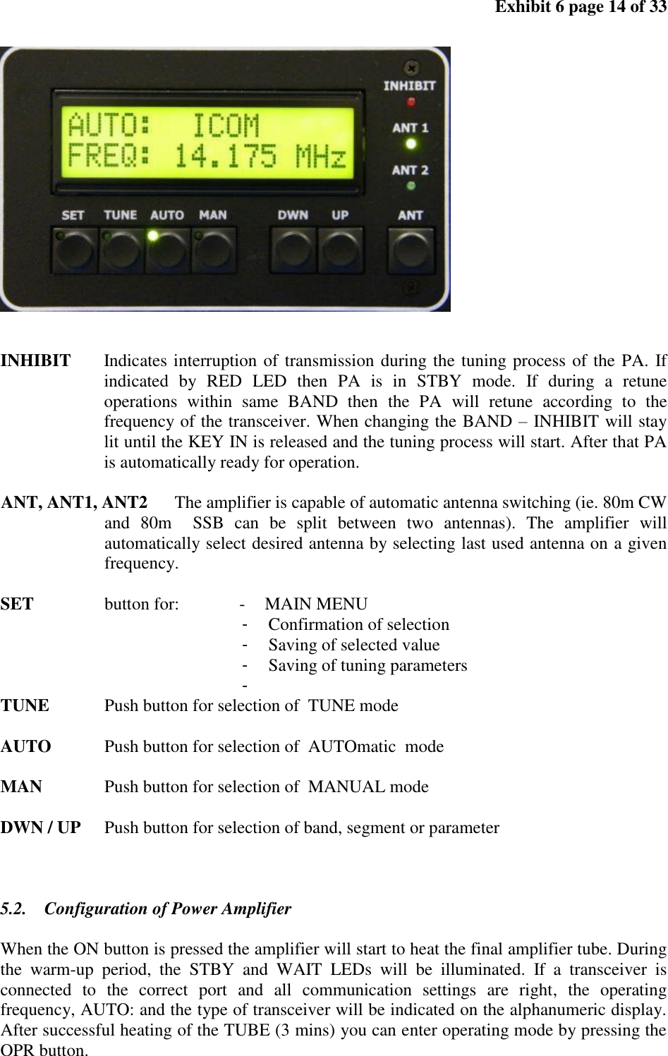
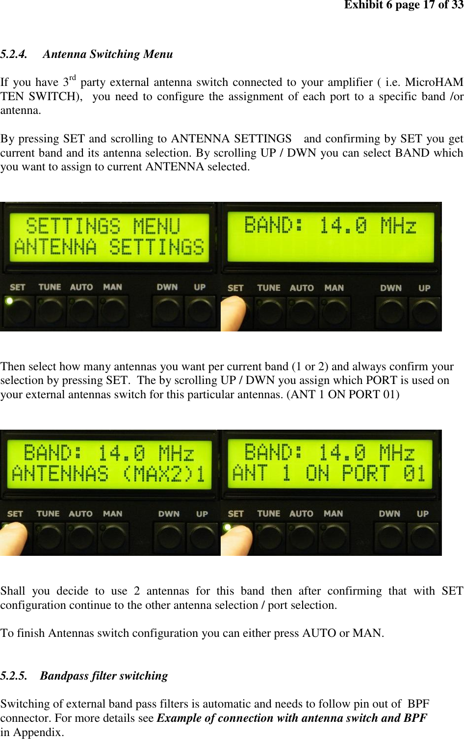
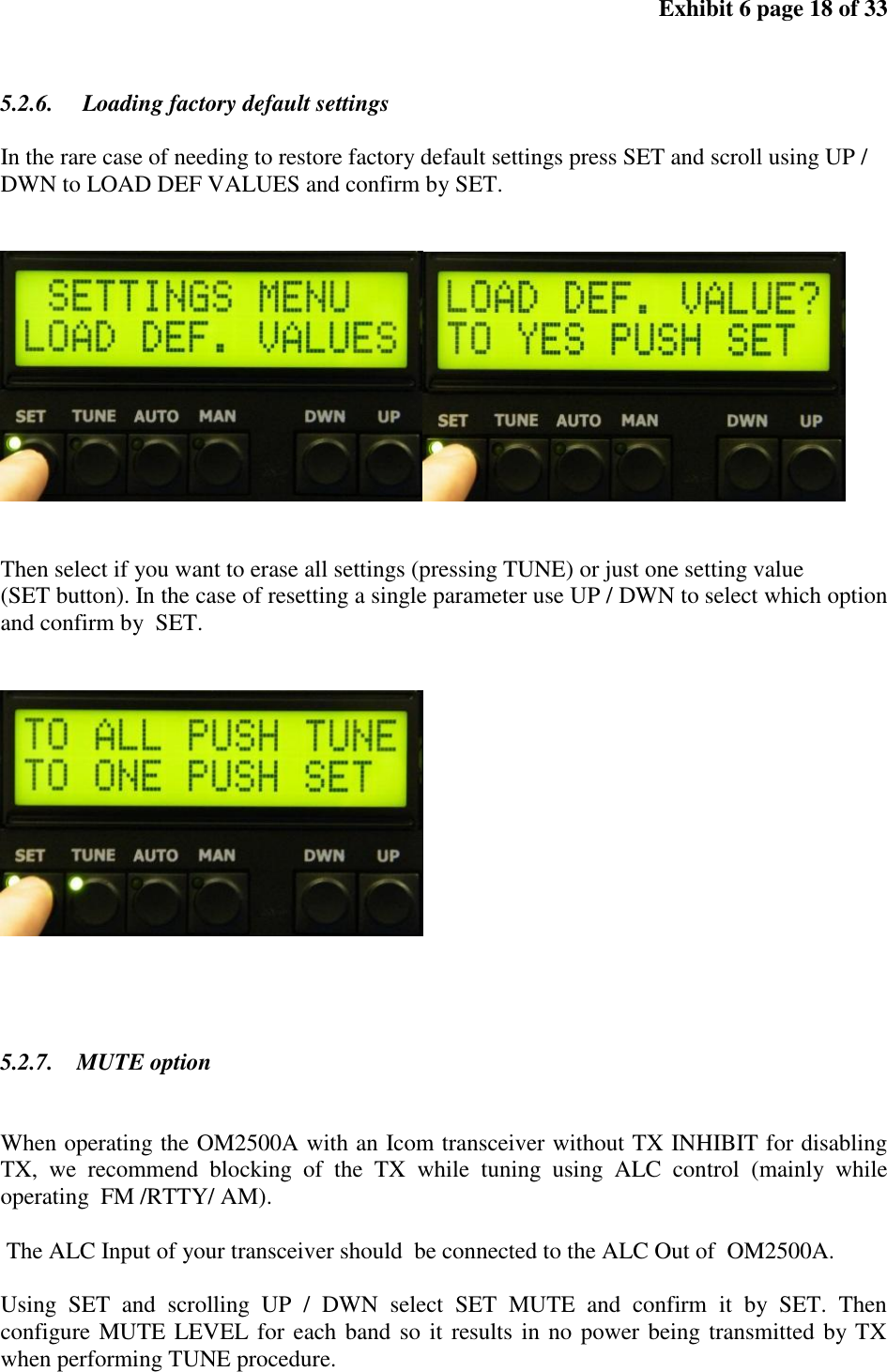
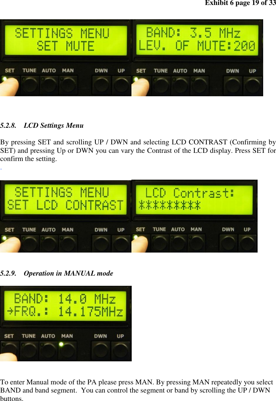
Array Solutions Array Solutions X8NOM2500A Amateur Radio High Frequency Linear Amplifier User Manual V eobecn popis KV zosilnovaca OM2500
Array Solutions dba Array Solutions Amateur Radio High Frequency Linear Amplifier V eobecn popis KV zosilnovaca OM2500
Contents
- 1. User's Manual EX 6
- 2. OM2500 Manual version of OM2500A
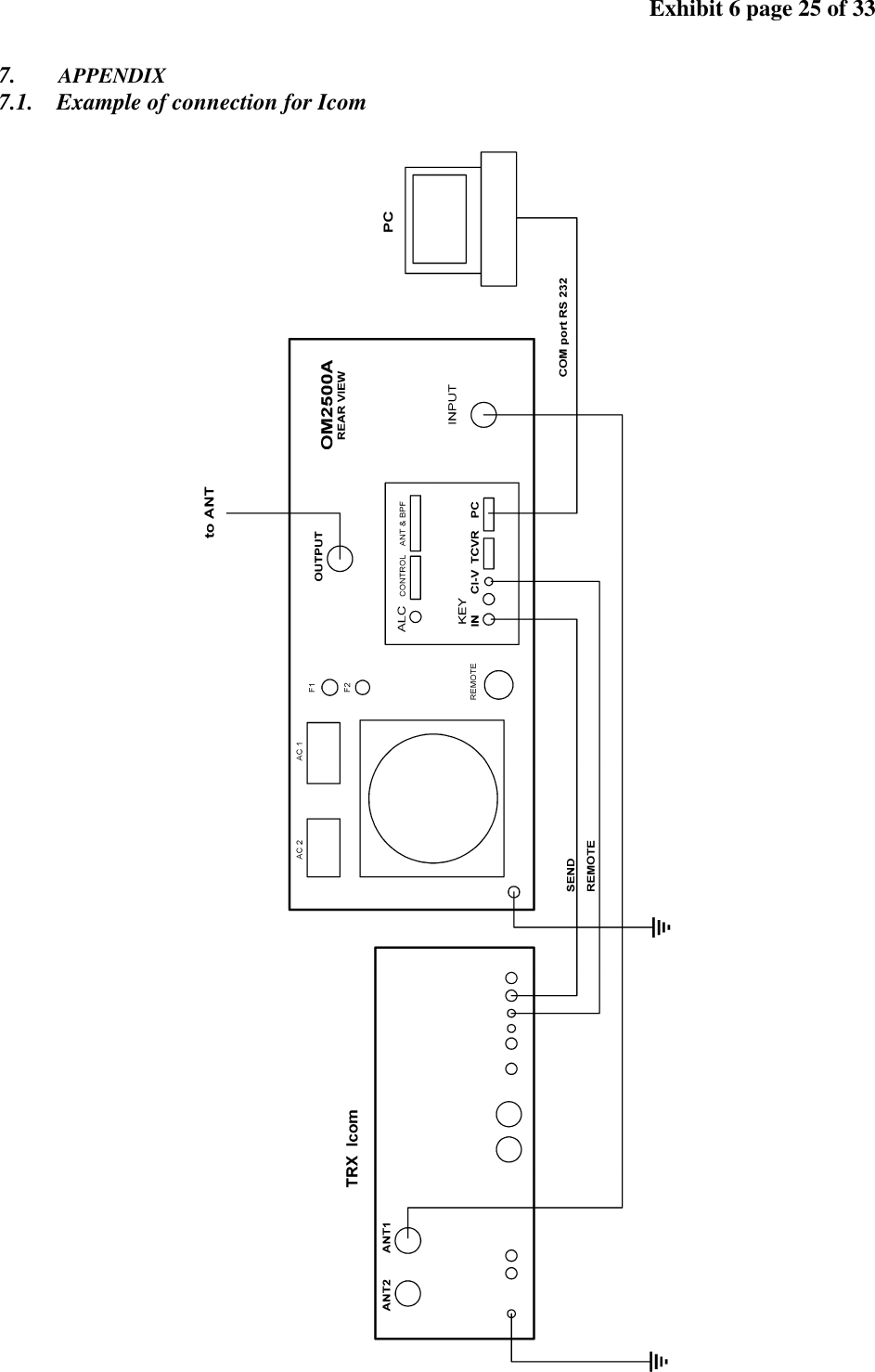
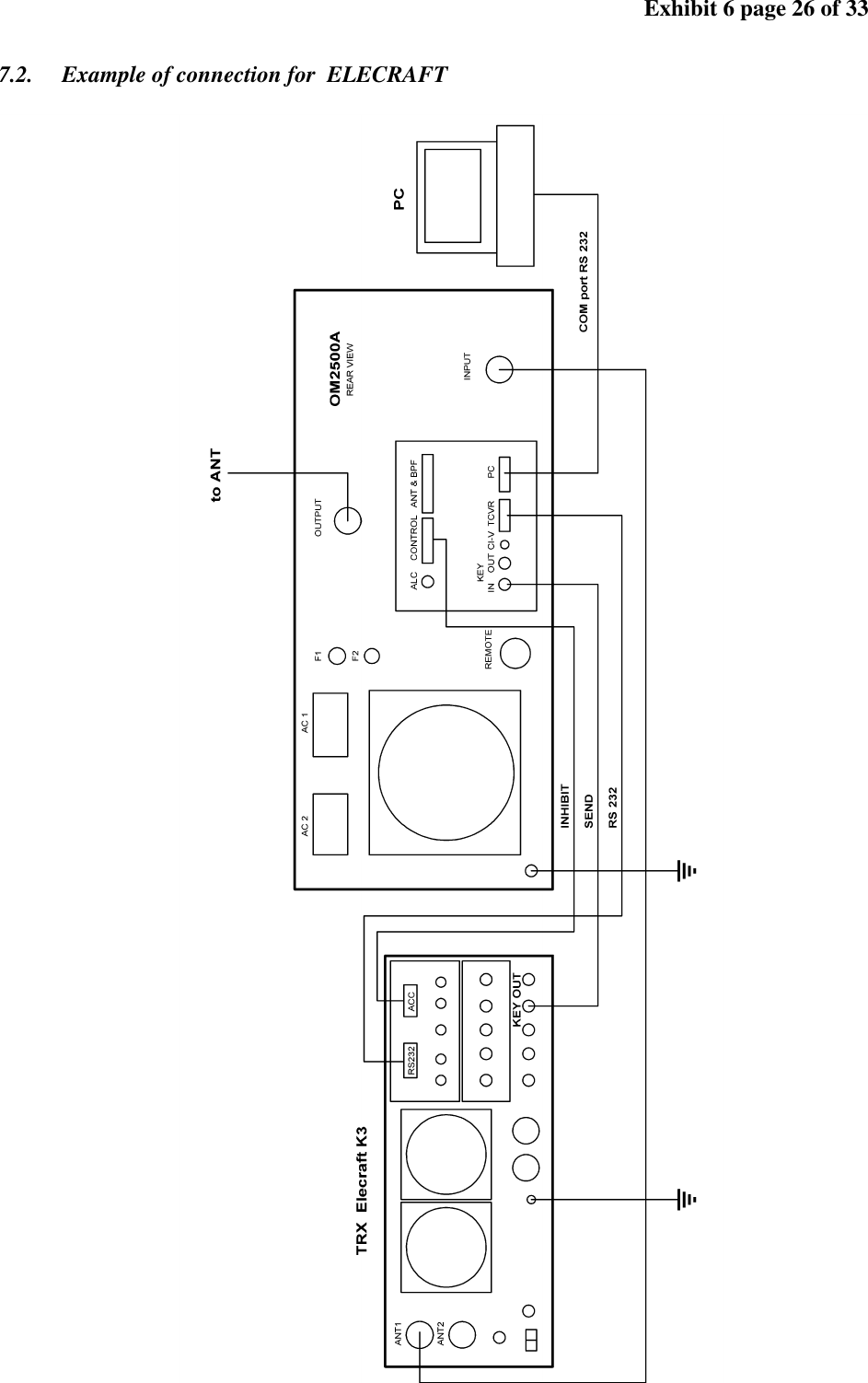
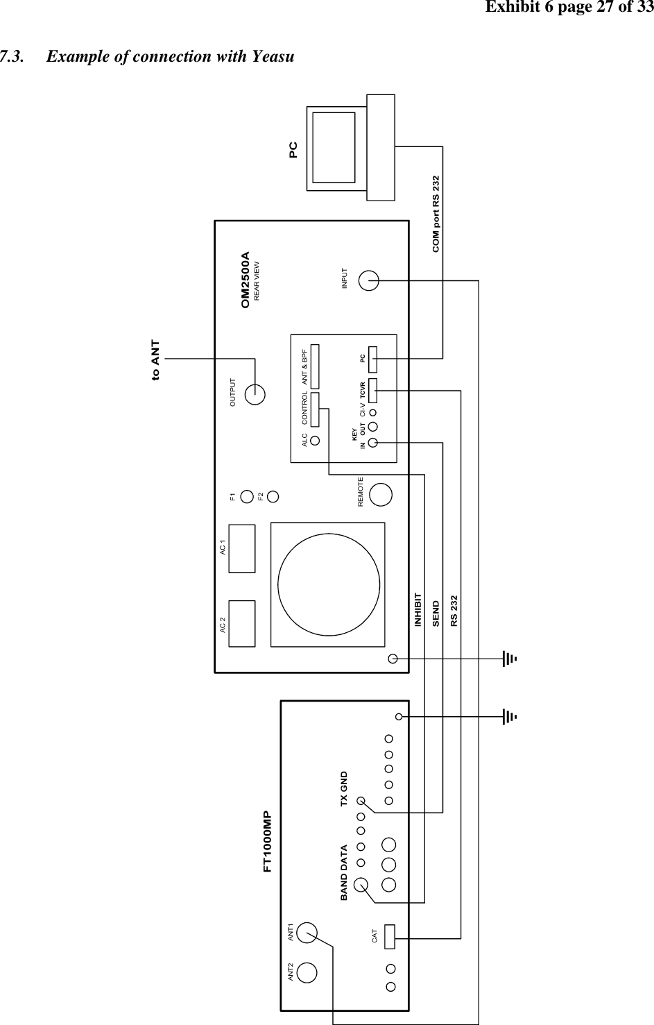
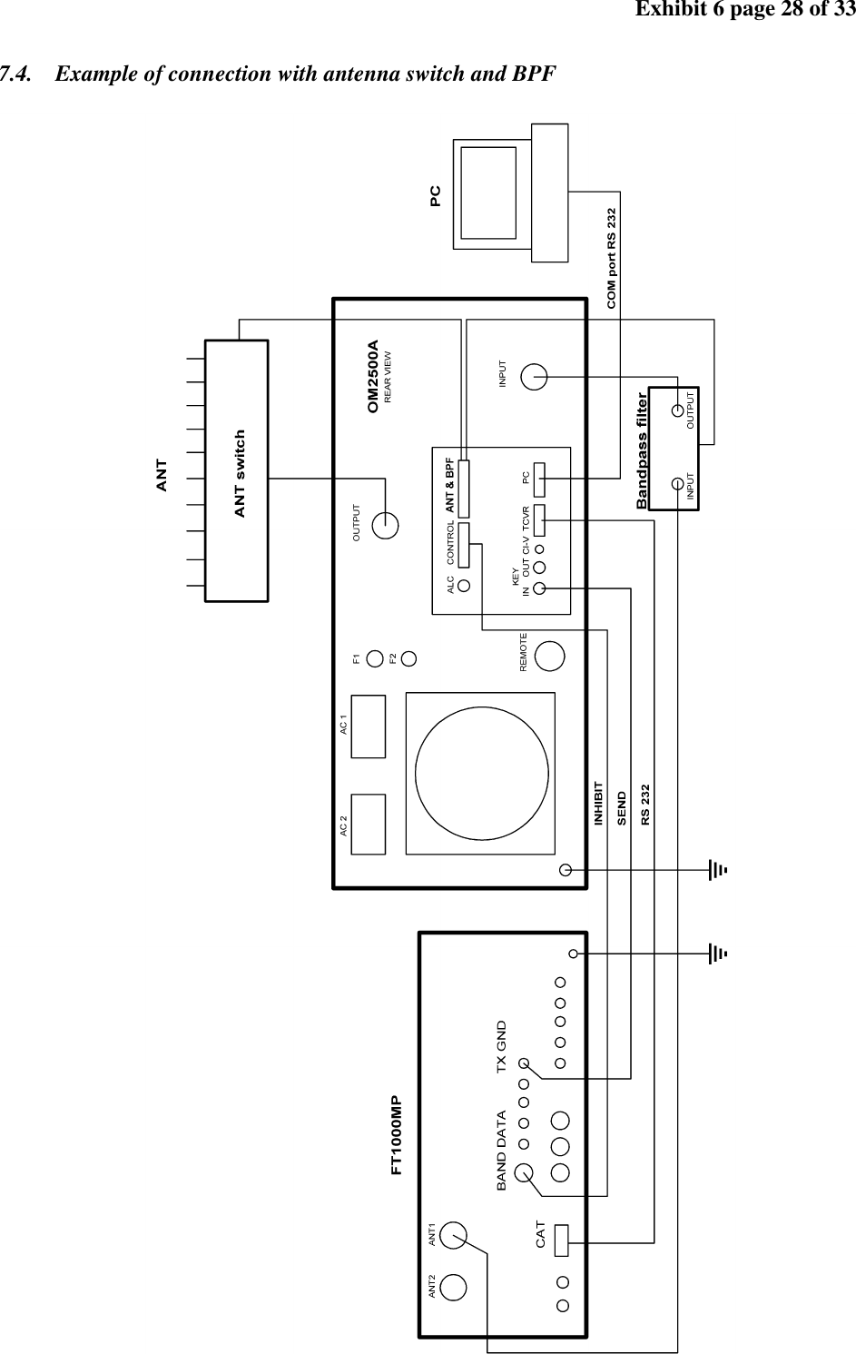
User's Manual EX 6
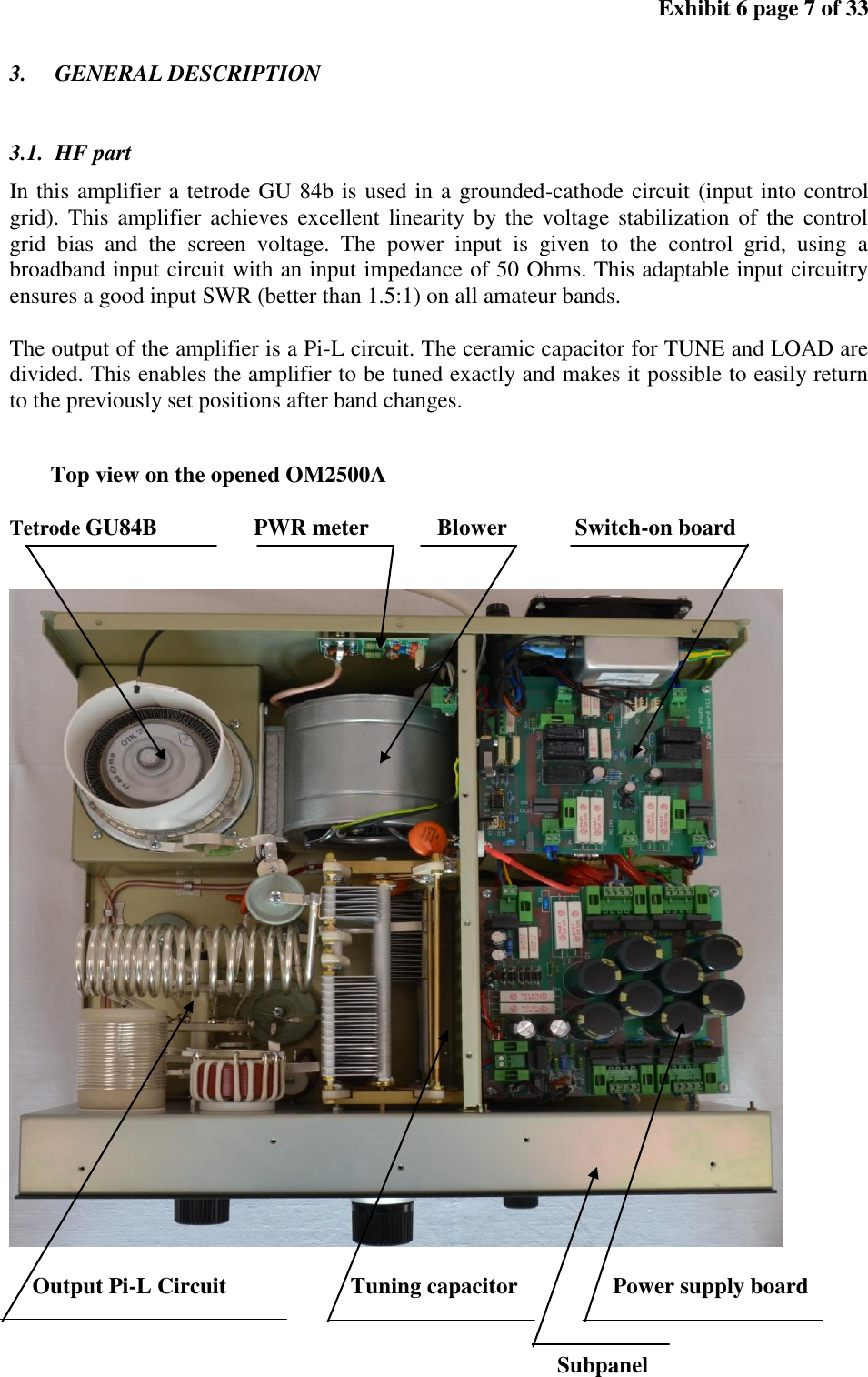
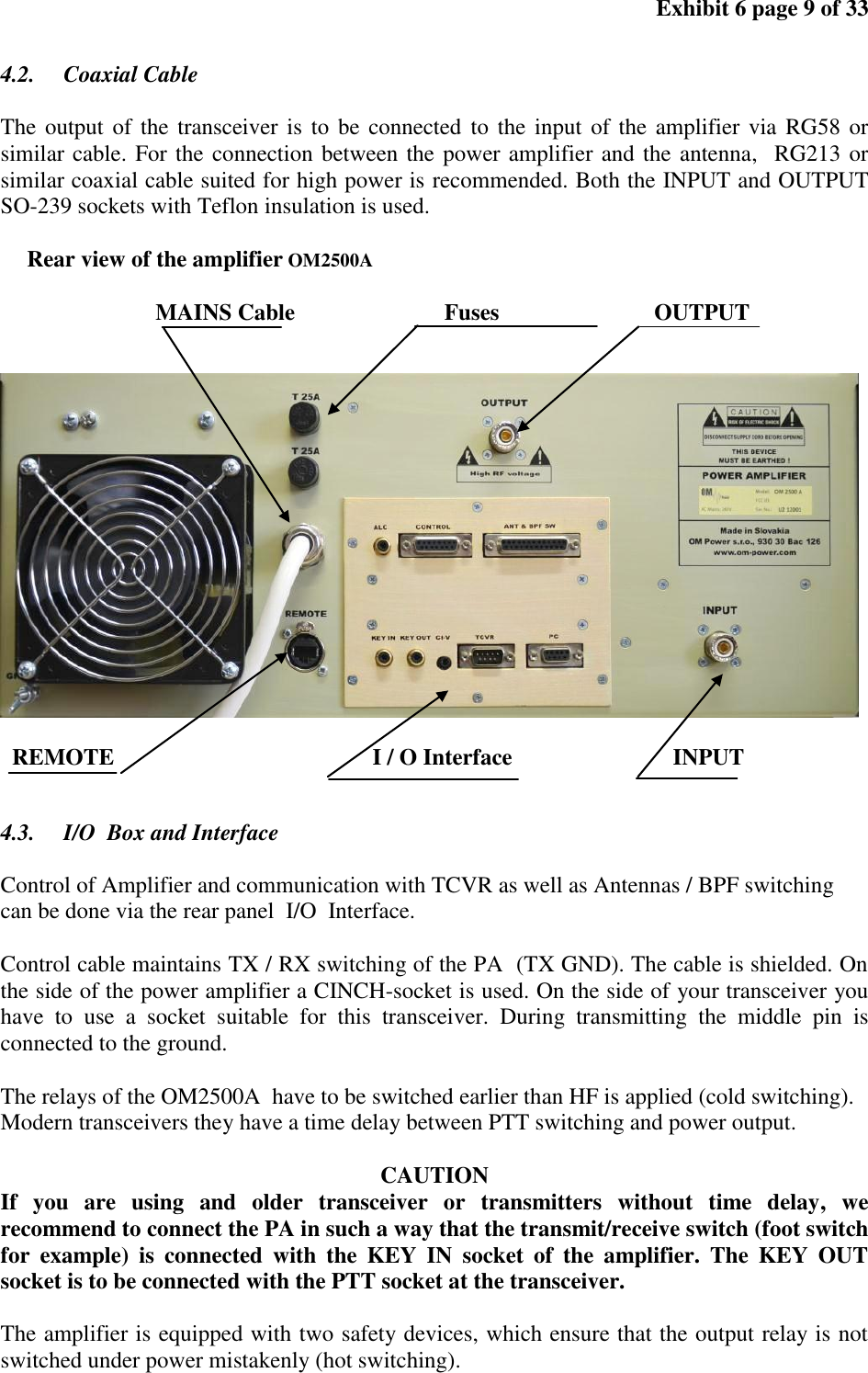
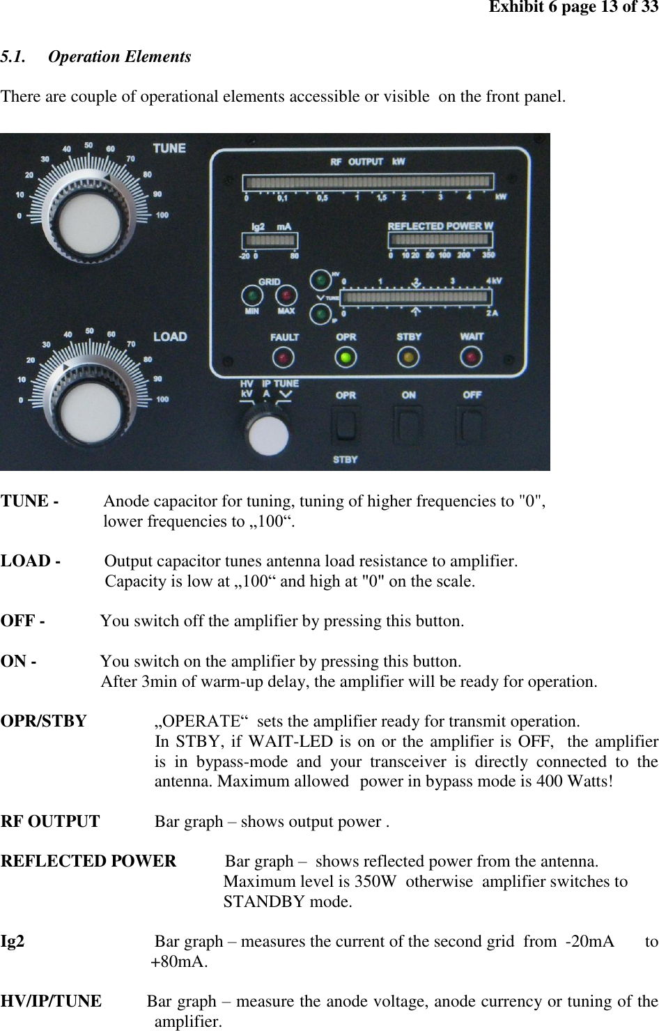
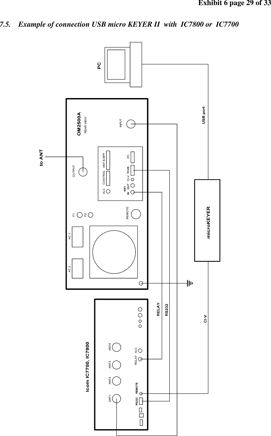
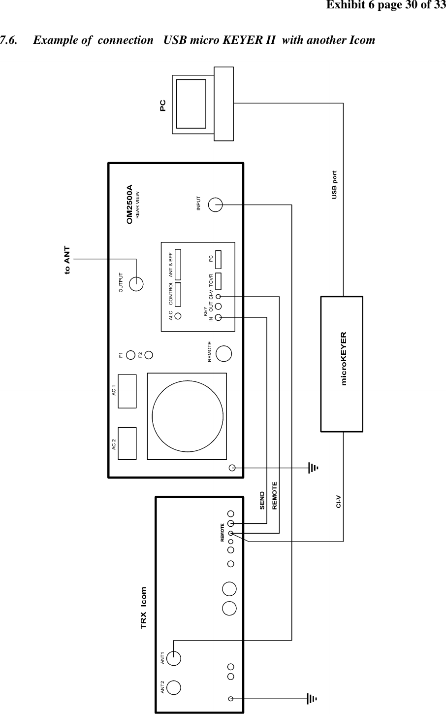
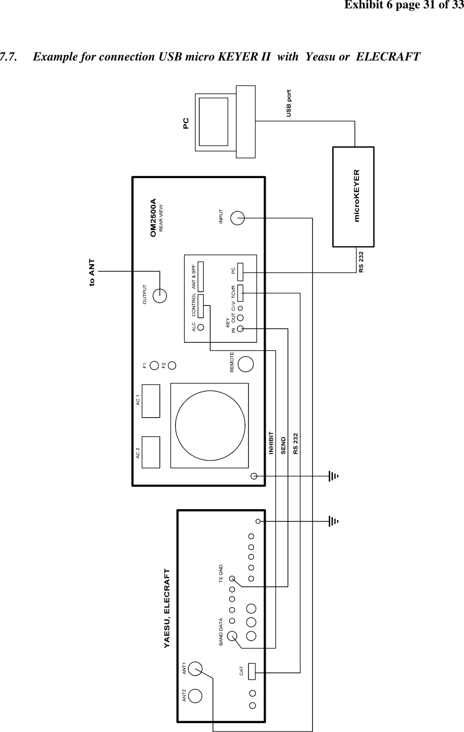
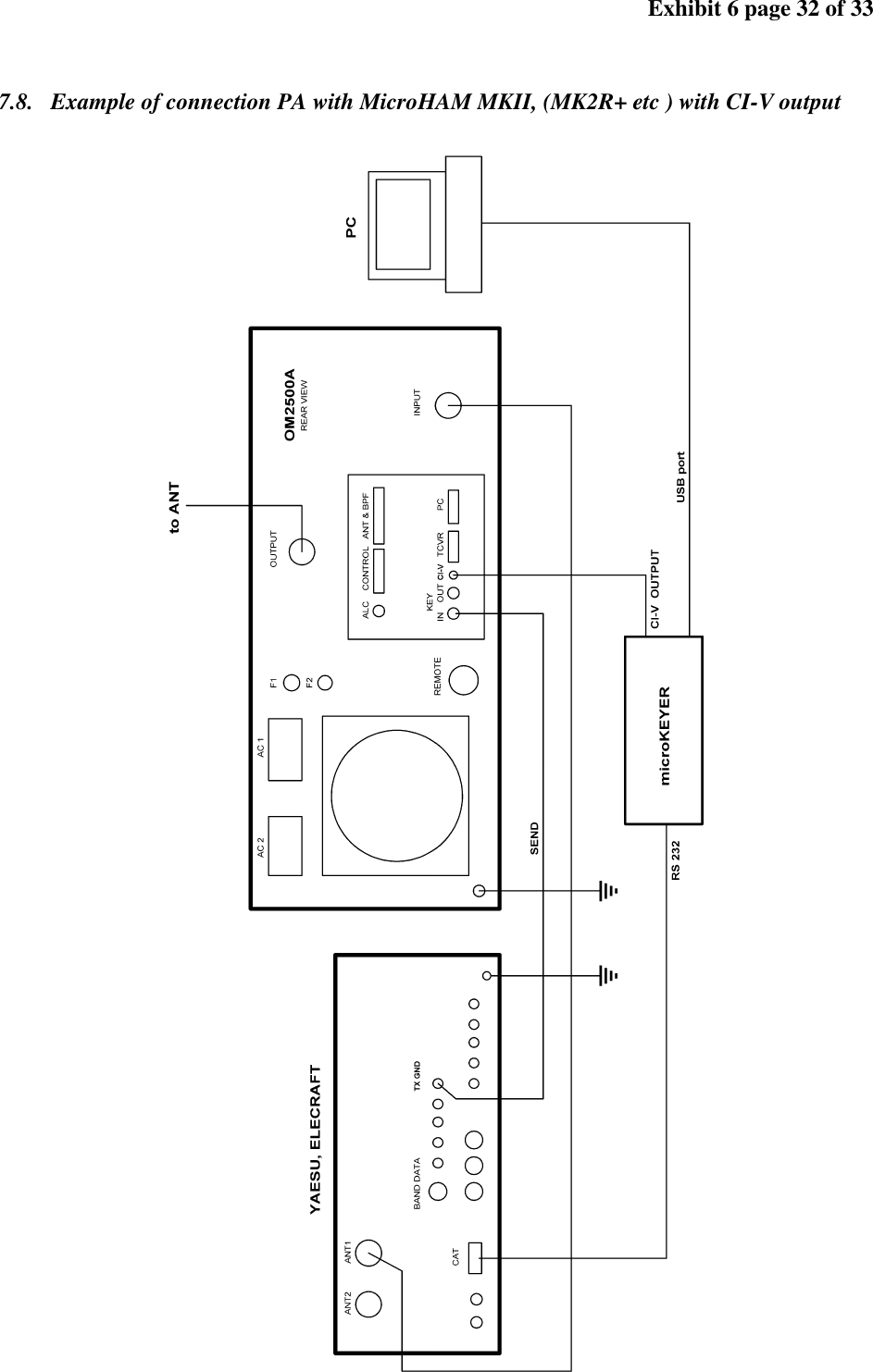
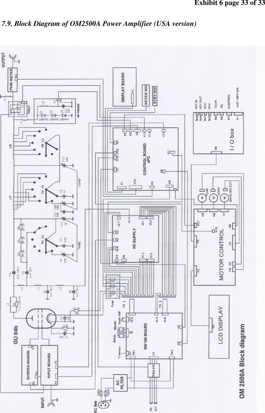
![Exhibit 6 page 4 of 33 1. GENERAL INFORMATION 1.1. Introduction The OM Power model OM2500A is a fully automatic, full legal limit amplifier, designed for heavy duty use on all short wave amateur bands from 1.8 to 29.7 MHz (including WARC bands) and all modes with no time limit. It is equipped with one GU84b ceramic tetrode. THE ADVANTAGES OF OM2500 A Full compatibility with: ICOM, ELECRAFT ,KENWOOD, TEN-TEC ORION , Yaesu and CI-V data. Automatic switching between bands Automatic tuning with the band according to segments Automatic switching of band pass filter Automatic switching of antenna switches The possibility to use 2 different antennas within one band or segment 1.2. Specification 1.2.1. Parameters Frequency Coverage Amateur Bands 1.8 – 29.7 MHz including WARC Power Output 1500w PEP continuous output all modes - *no time limit* Input Power 60 – 80W for full output power Input Impedance 50 Ohm, VSWR < 1.2 : 1 Power Gain 15 dB Output impedance 50 Ohm unbalanced Maximum output SWR 2:1 SWR protection: automatic switching to STBY , when reflected power is 350Wor higher Intermodulation distortion 36 dB below nominal output Suppression of harmonics < -52 dBc second, < -65 dBc third Tube GU84b Ceramic tetrode Cooler Centrifugal blower + axial blower Power supply 240 V - 60 Hz Transformers 2 pcs of toroidal transformer 2,0 kVA Parameters 485 mm x 200 mm x 455 mm [19.1” x 7.9” x 17.9”] (width x height x depth) Weight 41,5 kg ( 92 lb ) 1.2.2. Protection Circuits There are 8 special protection circuits used in the amplifier. They are activated when one or more of next parameters exceed defined values or some unwanted occasion occurs. VSWR too high Anode current too high](https://usermanual.wiki/Array-Solutions-Array-Solutions/X8NOM2500A.User-s-Manual-EX-6/User-Guide-1792475-Page-4.png)