Arris TM822R User Guide Manual TM822R:
User Manual: Arris TM822R TM822R: User Guide
Open the PDF directly: View PDF ![]() .
.
Page Count: 44

TM822R DOCSIS® 3.0 Telephony
Modem For XFINITY Customers
User Guide
STANDARD PN 365-095-31188 x.1
October 2016
SURFboard TM822R Telephony Modem User Guide
Release 8 STANDARD 1.0
ARRIS Copyrights and Trademarks
© 2016 ARRIS Enterprises LLC. All Rights Reserved.
No part of this publication may be reproduced in any form or by any means or used to make
any derivative work (such as translation, transformation, or adaptation) without written
permission from ARRIS Enterprises LLC. (“ARRIS”). ARRIS reserves the right to revise this
publication and to make changes in content from time to time without obligation on the part
of ARRIS to provide notification of such revision or change.
ARRIS and the ARRIS logo are all trademarks of ARRIS Enterprises LLC. Other trademarks and
trade names may be used in this document to refer to either the entities claiming the marks
or the names of their products. ARRIS disclaims proprietary interest in the marks and names
of others.
ARRIS provides this guide without warranty of any kind, implied or expressed, including, but
not limited to, the implied warranties of merchantability and fitness for a particular purpose.
ARRIS may make improvements or changes in the product(s) described in this manual at any
time.
The capabilities, system requirements and/or compatibility with third-party products
described herein are subject to change without notice.
Patent Notice
Protected under one or more of the following U.S. patents: http://www.arris.com/legal
Other patents pending.

STANDARD PN 365-095-31188 x.1 TM822R DOCSIS® 3.0 Telephony Modem For XFINITY Customers User Guide
© 2016 ARRIS Enterprises LLC. All Rights Reserved. 3
Table of Contents
1. Overview ................................................................................................................ 5
Introduction ....................................................................................................................... 5
Getting Support ................................................................................................................. 5
2. Safety Requirements ............................................................................................... 6
FCC Part 15 ........................................................................................................................ 7
RF Exposure ............................................................................................................... 8
Industry Canada Compliance ............................................................................................. 8
For Mexico ......................................................................................................................... 8
3. Getting Started ....................................................................................................... 9
About Your New Telephony Modem ................................................................................. 9
What's in the Box ............................................................................................................... 9
Items You Need ................................................................................................................. 9
Getting Service ................................................................................................................. 11
System Requirements ...................................................................................................... 11
Recommended Hardware ....................................................................................... 12
Windows ................................................................................................................. 12
Mac OS .................................................................................................................... 12
Linux/Unix ............................................................................................................... 12
About this Manual ........................................................................................................... 13
What About Security? ...................................................................................................... 13
Ethernet Connection ....................................................................................................... 14
4. Battery Installation and Removal .......................................................................... 15
Introduction ..................................................................................................................... 15
Basic Battery Installation and Replacement .................................................................... 17
Extended Battery Installation and Replacement ............................................................. 18
Maximum Battery Installation and Replacement............................................................ 20
Battery Usage and Storage Conditions ............................................................................ 22
Battery Disposal Guidelines .................................................................................... 22
Getting Battery Status ..................................................................................................... 22
5. Installing and Connecting your Telephony Modem ................................................ 23
Front Panel ...................................................................................................................... 24
Rear Panel ........................................................................................................................ 25
Selecting an Installation Location .................................................................................... 25
Mounting the Telephony Modem ................................................................................... 26

STANDARD PN 365-095-31188 x.1 TM822R DOCSIS® 3.0 Telephony Modem For XFINITY Customers User Guide
© 2016 ARRIS Enterprises LLC. All Rights Reserved. 4
Tools and Materials ................................................................................................ 26
Location ................................................................................................................... 26
Wall Mounting Instructions .................................................................................... 26
Desktop Mounting Instructions .............................................................................. 28
Connecting the Telephony Modem ................................................................................. 29
6. Configuring Your Ethernet Connection ................................................................... 31
Requirements .................................................................................................................. 31
How to use this Chapter .................................................................................................. 31
TCP/IP Configuration for Windows Vista ......................................................................... 31
TCP/IP Configuration for Windows 7, Windows 8, or Windows 10 ................................ 32
TCP/IP Configuration for Mac OS X ................................................................................. 32
7. Using the Telephony Modem................................................................................. 34
Setting up Your Computer to Use the Telephony Modem .............................................. 34
Indicator Lights for the TM822R ...................................................................................... 34
Battery Mismatch ................................................................................................... 35
Wiring Problems ..................................................................................................... 35
Patterns: Normal Operation ................................................................................... 35
Patterns: Startup Sequence .................................................................................... 36
Using the Reset Button ........................................................................................... 37
Booting from Battery .............................................................................................. 37
8. Troubleshooting .................................................................................................... 38
The Telephony Modem is plugged in, but the Power light is Off .................................... 38
I'm not getting on the Internet ........................................................................................ 38
I'm not getting on the Internet (Ethernet) ...................................................................... 38
I can get on the Internet, but everything is slow ............................................................ 39
I don't have a dial tone when I pick up the phone - why? .............................................. 39
9. Glossary ................................................................................................................ 41
STANDARD PN 365-095-31188 x.1 TM822R DOCSIS® 3.0 Telephony Modem For XFINITY Customers User Guide
© 2016 ARRIS Enterprises LLC. All Rights Reserved. 5
Chapter 1
Overview
Introduction
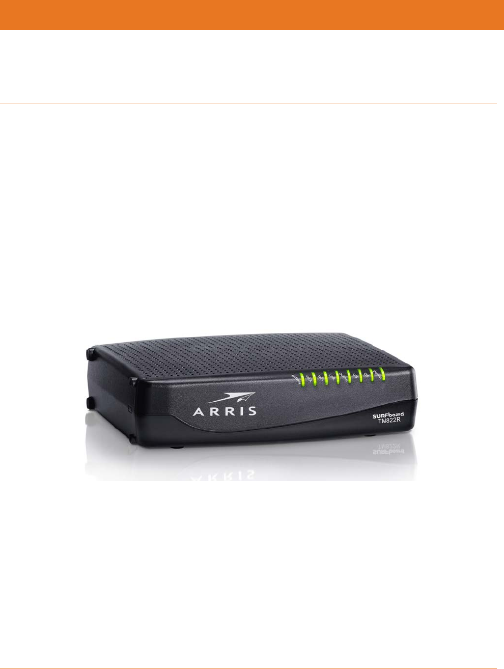
Get ready to experience the Internet’s express lane! Whether you’re checking out streaming
media, downloading new software, checking your email, or talking with friends on the
phone, the SURFboard TM822R Telephony Modem brings it all to you faster and more
reliably. All while providing toll quality Voice over IP telephone service. It also provides
Lithium-Ion battery backup capability to provide continued telephone service during power
outages.
The SURFboard TM822R Telephony Modem provides an Ethernet connection for use with
either a single computer or home/office Local Area Network (LAN). In addition, the TM822R
provides for up to two separate lines of telephone service.
Installation is simple and your service provider will provide assistance to you for any special
requirements.
Getting Support
If you need assistance with your ARRIS product please contact your service provider.
For additional technical information and product User Guides please visit the ARRIS Support
website at http://www.arris.com/consumers.

STANDARD PN 365-095-31188 x.1 TM822R DOCSIS® 3.0 Telephony Modem For XFINITY Customers User Guide
© 2016 ARRIS Enterprises LLC. All Rights Reserved. 6
Chapter 2
Safety Requirements
The ARRIS Telephony Modem complies with the applicable requirements for performance,
construction, labeling, and information when used as outlined below:
CAUTION
Potential equipment damage
Potential loss of service
Connecting the Telephony Modem to existing telephone wiring should only be performed by
a professional installer. Physical connections to the previous telephone provider must be
removed and the wiring must be checked; there must not be any voltages. Cancelation of
telephone service is not adequate. Failure to do so may result in loss of service and/or
permanent damage to the Telephony Modem.
CAUTION
Risk of shock
Mains voltages inside this unit. No user serviceable parts inside. Refer service to qualified
personnel only!
CAUTION
Risk of explosion
Replacing the battery with an incorrect type, heating a battery above 75°C, or incinerating a
battery, can cause product failure and a risk of fire or battery explosion. Do not dispose of in
fire. Recycle or dispose of used batteries responsibly and in accordance with local
ordinances.
The Telephony Modem is designed to be connected directly to a telephone.
Connecting the Telephony Modem to the home’s existing telephone wiring should only
be performed by a professional installer.
Do not use product near water (i.e. wet basement, bathtub, sink or near a swimming
pool, etc.), to avoid risk of electrocution.
Do not use the telephone to report a gas leak in the vicinity of the leak.
The product shall be cleaned using only a damp, lint-free, cloth. No solvents or cleaning
agents shall be used.
Do not use spray cleaners or aerosols on the device.
Avoid using and/or connecting the equipment during an electrical storm, to avoid risk of
electrocution.

Chapter 2: Safety Requirements
STANDARD PN 365-095-31188 x.1 TM822R DOCSIS® 3.0 Telephony Modem For XFINITY Customers User Guide
© 2016 ARRIS Enterprises LLC. All Rights Reserved. 7
Do not locate the equipment within 6 feet (1.9 m) of a flame or ignition source (i.e. heat
registers, space heaters, fireplaces, etc.).
Use only the AC power adapter (if provided) and power cord included with the
equipment.
Equipment should be installed near the power outlet and should be easily accessible.
The shield of the coaxial cable must be connected to earth (grounded) at the entrance to
the building in accordance with applicable national electrical installation codes. In the
U.S., this is required by NFPA 70 (National Electrical Code) Article 820. In the European
Union and in certain other countries, CATV installation equipotential bonding
requirements are specified in IEC 60728-11, Cable networks for television signals, sound
signals and interactive services, Part 11: Safety. This equipment is intended to be
installed in accordance with the requirements of IEC 60728-11 for safe operation.
If the equipment is to be installed in an area serviced by an IT power line network, as is
found in many areas of Norway, special attention should be given that the installation is
in accordance with IEC 60728-11, in particular Annex B and Figure B.4.
In areas of high surge events or poor grounding situations and areas prone to lightning
strikes, additional surge protection may be required (i.e. PF11VNT3 from American
Power Conversion) on the AC, RF, Ethernet and Phone lines.
When the Telephony Modem is connected to a local computer through Ethernet cables,
the computer must be properly grounded to the building/residence AC ground network.
All plug-in cards within the computer must be properly installed and grounded to the
computer frame per the manufacturer’s specifications.
Ensure proper ventilation. Position the Telephony Modem so that air flows freely around
it and the ventilation holes on the unit are not blocked.
Do not mount the Telephony Modem on surfaces that are sensitive to heat and/or which
may be damaged by the heat generated by the modem, its power supply, or other
accessories.
FCC Part 15
This equipment has been tested and found to comply with the requirements for a Class B
digital device under Part 15 of the Federal Communications Commission (FCC) rules. These
requirements are intended to provide reasonable protection against harmful interference in
a residential installation. This equipment generates, uses and can radiate radio frequency
energy and, if not installed and used in accordance with the instructions, may cause harmful
interference to radio communications. However, there is no guarantee that interference will
not occur in a particular installation. If this equipment does cause harmful interference to
radio or television reception, which can be determined by turning the equipment off and on,
the user is encouraged to try to correct the interference by one or more of the following
measures:
Reorient or relocate the receiving antenna.
Increase the separation between the equipment and receiver.
Connect the equipment into an outlet on a circuit different from that to which the
receiver is connected.

Chapter 2: Safety Requirements
STANDARD PN 365-095-31188 x.1 TM822R DOCSIS® 3.0 Telephony Modem For XFINITY Customers User Guide
© 2016 ARRIS Enterprises LLC. All Rights Reserved. 8
Consult the dealer or an experienced radio/TV technician for help.
FCC Caution
Changes or modifications to this equipment not expressly approved by the party responsible
for compliance could void the user’s authority to operate the equipment.
RF Exposure
This equipment complies with FCC radiation exposure limits set forth for an uncontrolled
environment. This equipment should be installed and operated with minimum distance of
11.8 inches (30 cm) between the radiator and your body. This transmitter must not be co-
located or operating in conjunction with any other antenna or transmitter.
Industry Canada Compliance
Under Industry Canada regulations, this radio transmitter may only operate using an
antenna of a type and maximum (or lesser) gain approved for the transmitter by Industry
Canada. To reduce potential radio interference to other users, the antenna type and its gain
should be so chosen that the equivalent isotropically radiated power (e.i.r.p.) is not more
than that necessary for successful communication.
This device complies with Industry Canada license-exempt RSS standard(s). Operation is
subject to the following two conditions: (1) this device may not cause interference, and (2)
this device must accept any interference, including interference that may cause undesired
operation of the device.
For Mexico
The operation of this equipment is subject to the following two conditions: (1) This
equipment or device cannot cause harmful interference and (2) this equipment or device
must accept any interference, including interference that may cause some unwanted
operation of the equipment.

STANDARD PN 365-095-31188 x.1 TM822R DOCSIS® 3.0 Telephony Modem For XFINITY Customers User Guide
© 2016 ARRIS Enterprises LLC. All Rights Reserved. 9
Chapter 3
Getting Started
About Your New Telephony Modem
The SURFboard TM822R Telephony Modem is DOCSIS 3.0 compliant with the following
features:
Speed: much faster than dialup or ISDN service; up to eight times faster than DOCSIS 2.0
cable modems.
Connectivity: supports Ethernet connection.
Flexibility: provides two independent lines of telephone service as well as high speed
data.
Compatibility:
• Data services: DOCSIS 3.0 compliant and backward-compatible with DOCSIS 2.0 or
1.1; supports tiered data services (if offered by your service provider).
• Telephony services: PacketCable™ 1.5 or 1.0 compliant.
What's in the Box
Make sure you have the following items before proceeding. Call your service provider for
assistance if anything is missing.
Telephony Modem.
Power Cord.
Battery.
Quick Installation Guide.
Wall-Mounting Template and Instructions.
Ethernet Cable (CAT5e).
End User License Agreement.
Items You Need
If you are installing the Telephony Modem yourself, make sure you have the following items
on hand before continuing:
Telephony Modem package: see What's in the Box (page 9) for a list of items in the
package.
Chapter 3: Getting Started
STANDARD PN 365-095-31188 x.1 TM822R DOCSIS® 3.0 Telephony Modem For XFINITY Customers User Guide
© 2016 ARRIS Enterprises LLC. All Rights Reserved. 10
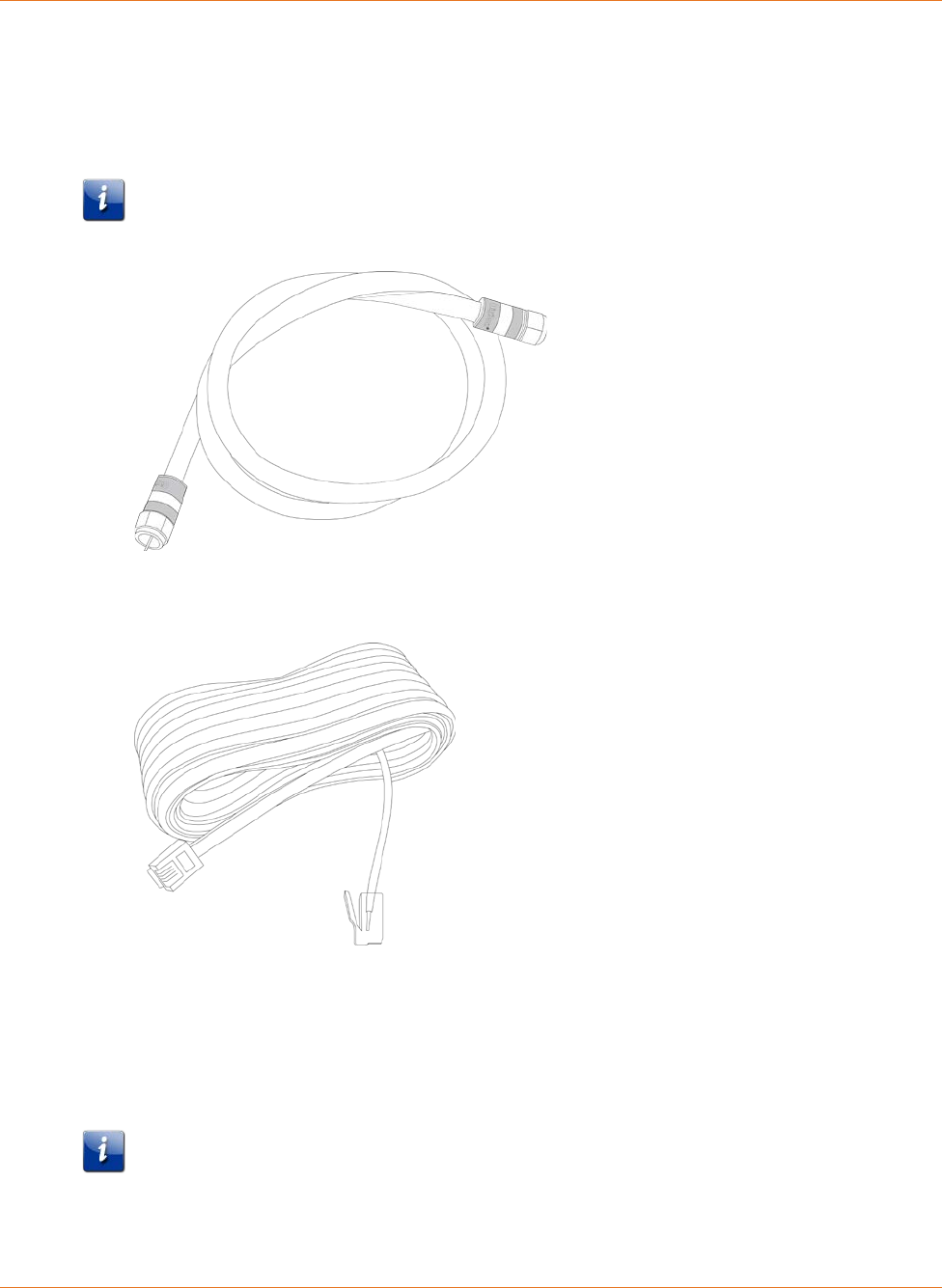
Coaxial cable (coax): This is a round cable with a connector on each end. It is the same
kind of wire used to connect to your television for cable TV. You can buy coax from any
electronics retailer and many discount stores; make sure it has connectors on both ends.
Be sure that the coax cable you choose has screw-on connectors. The coax should be
long enough to reach from your Telephony Modem to the nearest cable outlet.
Note: For best performance, use high-quality RG-6 type coax cable and minimize or
eliminate splitters between the cable jack and the Telephony Modem.
Phone Cable: This is a standard phone cable with standard phone connectors (RJ11 type)
on both ends. You can buy phone cables from any electronics retailer and many discount
stores.
Splitter (optional): provides an extra cable connection by splitting a single outlet into
two. You may need a splitter if you have a TV already connected to the cable outlet that
you want to use. You can buy a splitter from any electronics retailer and most discount
stores; you may also need a short piece of coax cable (with connectors); use it to connect
the splitter to the cable outlet and then connect the Telephony Modem and TV to the
splitter.
Note: A splitter effectively cuts the signal in half and sends each half to its two outputs.
Using several splitters in a line may deteriorate the quality of your television, telephone,
and/or internet connection.

Chapter 3: Getting Started
STANDARD PN 365-095-31188 x.1 TM822R DOCSIS® 3.0 Telephony Modem For XFINITY Customers User Guide
© 2016 ARRIS Enterprises LLC. All Rights Reserved. 11
Wall-mounting hardware (optional): if you want to wall-mount your Telephony Modem,
you need to obtain two drywall anchors or wood screws.
Information packet: your service provider should furnish you with a packet containing
information about your service and how to set it up. Read this information carefully and
contact your service provider if you have any questions.
Getting Service
Before trying to use your new Telephony Modem, contact your local service provider to
establish an Internet account and telephone service. When you call, have the following
information ready:
the Telephony Modem serial number and cable MAC addresses of the unit (printed on a
sticker on the bottom of the Telephony Modem).
the model number of the Telephony Modem.
If the Telephony Modem was provided by your service provider, they already have the
required information.
In addition, you should ask your service provider the following questions:
Do you have any special system requirements or files that I need to download after I am
connected?
When can I start using my Telephony Modem?
Do I need a user ID or password to access the Internet or my e-mail?
Will my phone number(s) change?
What new calling features will I have and how do I use them?
System Requirements
The Touchstone Telephony Modem operates with most computers. The following describes
requirements for each operating system; see the documentation for your system for details
on enabling and configuring networking.
To use the Telephony Modem, you need DOCSIS high-speed Internet service from your
service provider, as appropriate. Telephone service requires that the service provider has
PacketCable support.

Chapter 3: Getting Started
STANDARD PN 365-095-31188 x.1 TM822R DOCSIS® 3.0 Telephony Modem For XFINITY Customers User Guide
© 2016 ARRIS Enterprises LLC. All Rights Reserved. 12
Recommended Hardware
The following hardware configuration is recommended. Computers not meeting this
configuration can still work with the TM822R, but may not be able to make maximum use of
TM822R throughput.
CPU: P4, 3GHz or faster.
RAM: 1GB or greater.
Hard drive: 7200 RPM or faster.
Ethernet: Gig-E (1000BaseT).
Windows
Windows Vista, Windows 7, Windows 8, or Windows 10. A supported Ethernet LAN
connection must be available.
Mac OS
System 7.5 to Mac OS 9.2 (Open Transport recommended) or Mac OS X. A supported
Ethernet LAN connection must be available.
Linux/Unix
Hardware drivers, TCP/IP, and DHCP must be enabled in the kernel. A supported Ethernet
LAN connection must be available.
Chapter 3: Getting Started
STANDARD PN 365-095-31188 x.1 TM822R DOCSIS® 3.0 Telephony Modem For XFINITY Customers User Guide
© 2016 ARRIS Enterprises LLC. All Rights Reserved. 13
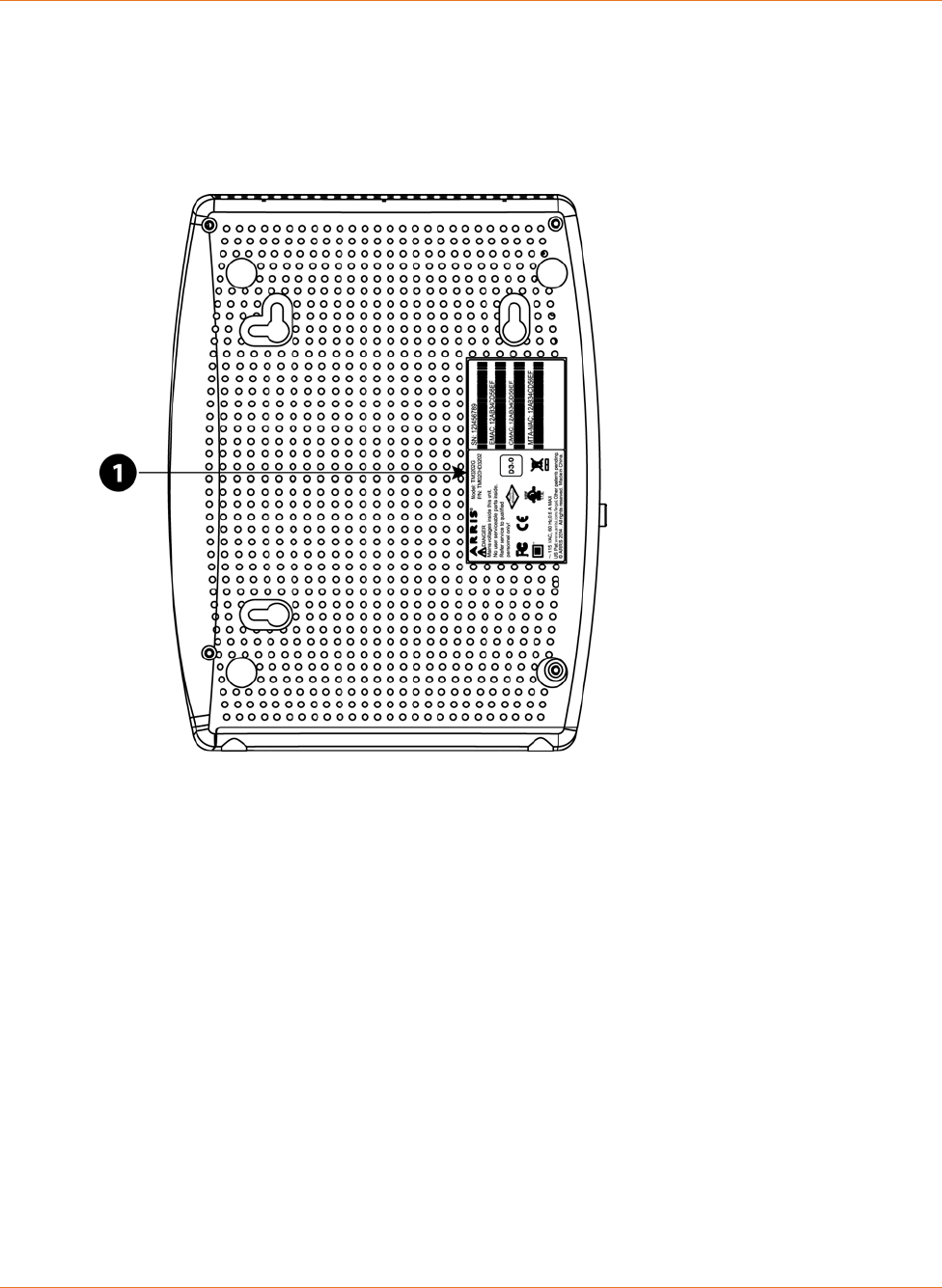
About this Manual
This manual covers the Touchstone TM822R Telephony Modem. The model number is on
the label affixed to the Telephony Modem.
1. Model Number
What About Security?
Having a high-speed, always-on connection to the Internet requires a certain amount of
responsibility to other Internet users—including the need to maintain a reasonably secure
system. While no system is 100% secure, you can use the following tips to enhance your
system’s security:
Keep the operating system of your computer updated with the latest security patches.
Run the system update utility at least weekly.
Keep your email program updated with the latest security patches. In addition, avoid
opening email containing attachments, or opening files sent through chat rooms,
whenever possible.
Install a virus checker and keep it updated.
Avoid providing web or file-sharing services over your Telephony Modem. Besides
certain vulnerability problems, most cable companies prohibit running servers on
consumer-level accounts and may suspend your account for violating your terms of
service.
Chapter 3: Getting Started
STANDARD PN 365-095-31188 x.1 TM822R DOCSIS® 3.0 Telephony Modem For XFINITY Customers User Guide
© 2016 ARRIS Enterprises LLC. All Rights Reserved. 14
Use the service provider’s mail servers for sending email.
Avoid using proxy software unless you are certain that it is not open for abuse by other
Internet users (some are shipped open by default). Criminals can take advantage of open
proxies to hide their identity when breaking into other computers or sending spam. If
you have an open proxy, your service provider may suspend your account to protect the
rest of the network.
Ethernet Connection
Ethernet is a standard method of connecting two or more computers into a Local Area
Network (LAN). You can use the Ethernet connection if your computer has built-in Ethernet
hardware.
Note: To connect more than one computer to the TM822R through the Ethernet port, you
need an Ethernet hub (available at computer retailers).
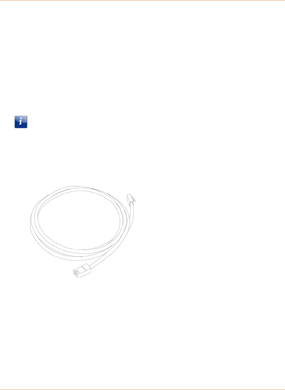
The Telephony Modem package comes with one Ethernet cable (the connectors look like
wide telephone connectors); you can purchase more cables if necessary at a computer
retailer. If you are connecting the Telephony Modem directly to a computer, or to an
Ethernet hub with a cross-over switch, ask for Category 5e (CAT5e) straight-through cable.
CAT5e cable is required for gigabit Ethernet (Gig-E), not regular CAT5 cable.
STANDARD PN 365-095-31188 x.1 TM822R DOCSIS® 3.0 Telephony Modem For XFINITY Customers User Guide
© 2016 ARRIS Enterprises LLC. All Rights Reserved. 15
Chapter 4
Battery Installation and Removal
Introduction
The TM822R Telephony Modem supports a Lithium-Ion backup battery to provide continued
telephone service during power outages. The battery backup is not intended to take the
place of AC power.
Note: The battery is intended only to provide emergency telephone service in the case of a
power outage. LED operation is reduced when the Telephony Modem is operating on battery
power.
Note: For safety and regulatory purposes, batteries are shipped outside of the Telephony
Modem and must be installed.
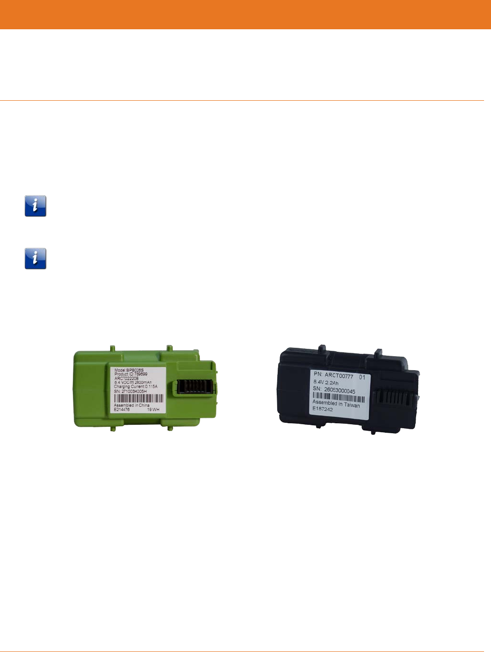
The TM822R supports the following battery models:
Basic backup battery: provides up to 6 hours (black) or 8 hours (green) of backup time,
depending on your Telephony Modem model and usage. It may be green or black.
Basic Backup Battery (Green) Basic Backup Battery (Black)
Refer to Basic Battery Installation and Replacement (page 17).
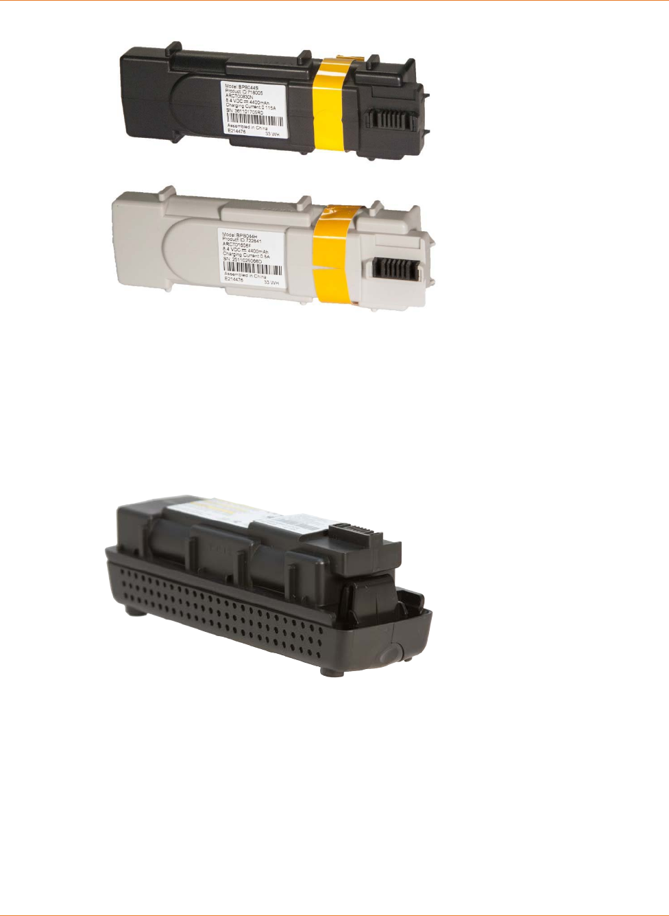
Extended backup battery: provides up to 12 hours of backup time, depending on model
and usage. It has a strap between the battery guides. It may be light gray or black.
Chapter 4: Battery Installation and Removal
STANDARD PN 365-095-31188 x.1 TM822R DOCSIS® 3.0 Telephony Modem For XFINITY Customers User Guide
© 2016 ARRIS Enterprises LLC. All Rights Reserved. 16
Extended Backup Battery
Refer to Extended Battery Installation and Replacement (page 18).
Maximum backup battery: provides up to 18 hours (6-cell) or 24 hours (8-cell) of backup
time, depending on model and usage. It replaces the battery door, and increases the
height of the Telephony Modem by about 5/8" (16 mm).
Maximum Backup Battery
Refer to Maximum Battery Installation and Replacement (page 20)
Your service provider may include a backup battery with your Telephony Modem. If you
wish, you can purchase an additional battery at http://shop.surfboard.com/. The website will
list the recommended battery type for your Telephony Modem.
Note: The backup times shown here are only an estimate and assume that your battery is
fully charged. If your battery is partially discharged (for example, if it is in the middle of a
self-test or is not yet fully charged), then your backup time will be reduced.
Chapter 4: Battery Installation and Removal
STANDARD PN 365-095-31188 x.1 TM822R DOCSIS® 3.0 Telephony Modem For XFINITY Customers User Guide
© 2016 ARRIS Enterprises LLC. All Rights Reserved. 17
Basic Battery Installation and Replacement
This model of the Telephony Modem has the ability to provide continued telephone service
during power outages. The battery backup is not intended to take the place of AC power.
Use this procedure to install and to replace the backup battery.
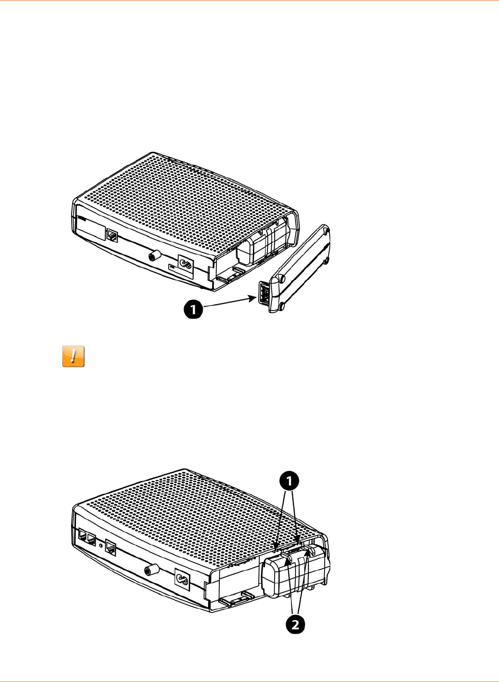
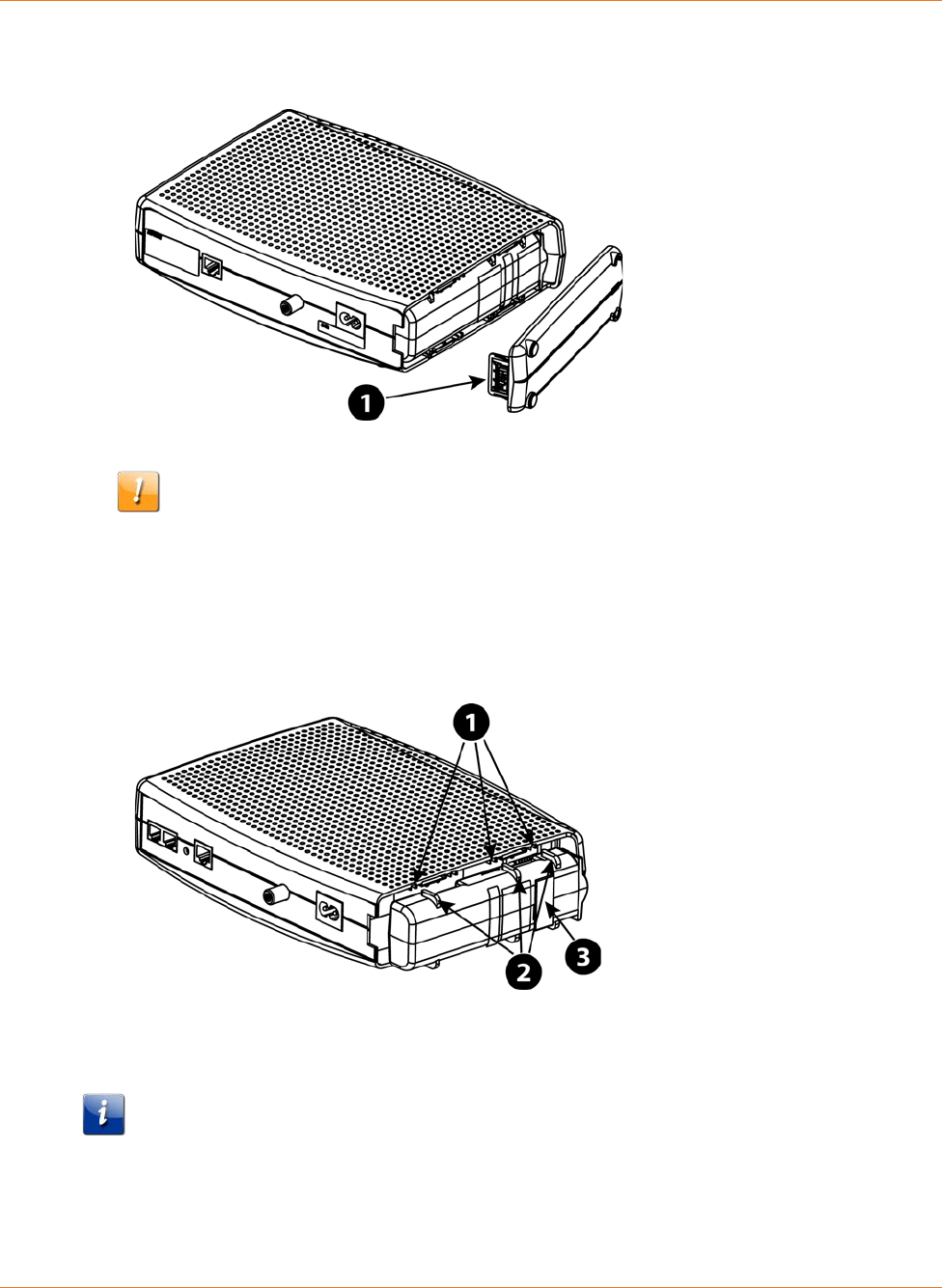
1. Press down and pull back on the latch holding the battery door (on the bottom of the
Telephony Modem). Pull the door toward you. Set the door aside in a safe place.
1 - Latch End
CAUTION
Risk of equipment damage
Improperly inserting the battery may damage the battery connector in the
Telephony Modem. Carefully follow the instructions in the next step to avoid
damage.
2. Hold the battery pack so that the guides on the battery align with the slots on the
Telephony Modem and slide the battery into the bay.
1 - Battery Slots
2 - Battery Guides
Chapter 4: Battery Installation and Removal
STANDARD PN 365-095-31188 x.1 TM822R DOCSIS® 3.0 Telephony Modem For XFINITY Customers User Guide
© 2016 ARRIS Enterprises LLC. All Rights Reserved. 18
Note: Batteries will not insert completely into the Telephony Modem if not oriented
correctly. The battery should slide into the bay without significant force. Line up the
guides on the battery with the slots in the battery bay.
3. Push the battery pack into the bay until it seats into place. If you are taking the battery
out of the Telephony Modem, position your finger in the battery opening area and use
leverage to dislodge the battery while pulling it straight back.
Note: The Telephony Modem will not begin operating until you apply AC power.
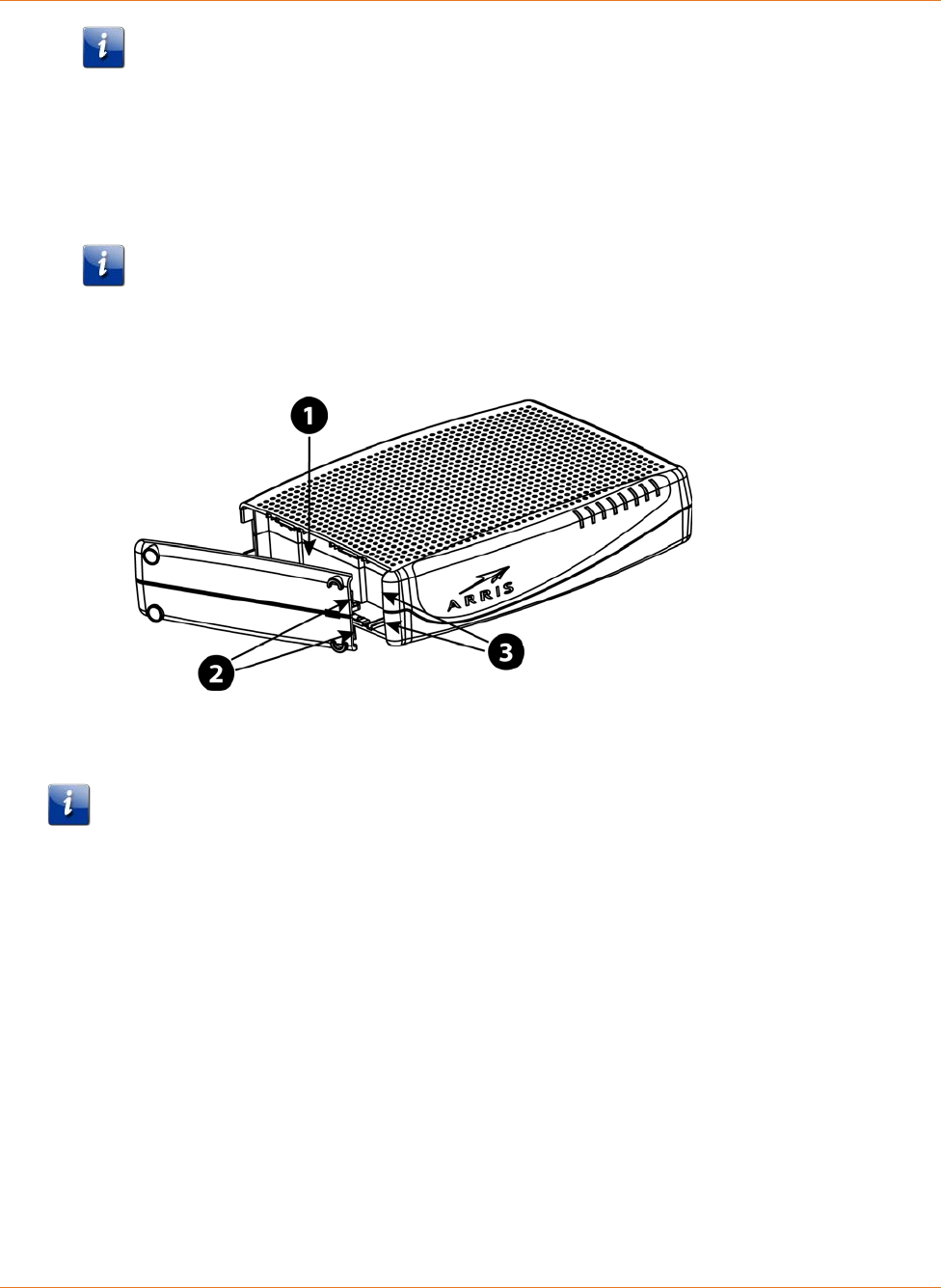
4. Replace the door. To do so, place the hinge tabs of the battery door into the receiver
slots inside the Telephony Modem battery compartment on the -opposite end of the
battery opening. Rotate the door toward the unit until the latch snaps back into place.
1 - Battery Compartment
2 - Hinge Tabs
3 - Receiver Slots
Note: Telephony Modems use a Lithium-Ion battery pack. Please recycle or dispose of the
battery responsibly and in accordance with local ordinances.
Extended Battery Installation and Replacement
This model of the Telephony Modem has the ability to provide continued telephone service
during power outages. The battery backup is not intended to take the place of AC power.
Use this procedure to install or replace the backup battery.
Chapter 4: Battery Installation and Removal
STANDARD PN 365-095-31188 x.1 TM822R DOCSIS® 3.0 Telephony Modem For XFINITY Customers User Guide
© 2016 ARRIS Enterprises LLC. All Rights Reserved. 19
1. Press down and pull back on the latch holding the battery door (on the bottom of the
Telephony Modem). Pull the door toward you. Set the door aside in a safe place.
1 - Latch End
CAUTION
Risk of equipment damage
Improperly inserting the battery may damage the battery connector in the
Telephony Modem. Carefully follow the instructions in the next step to avoid
damage.
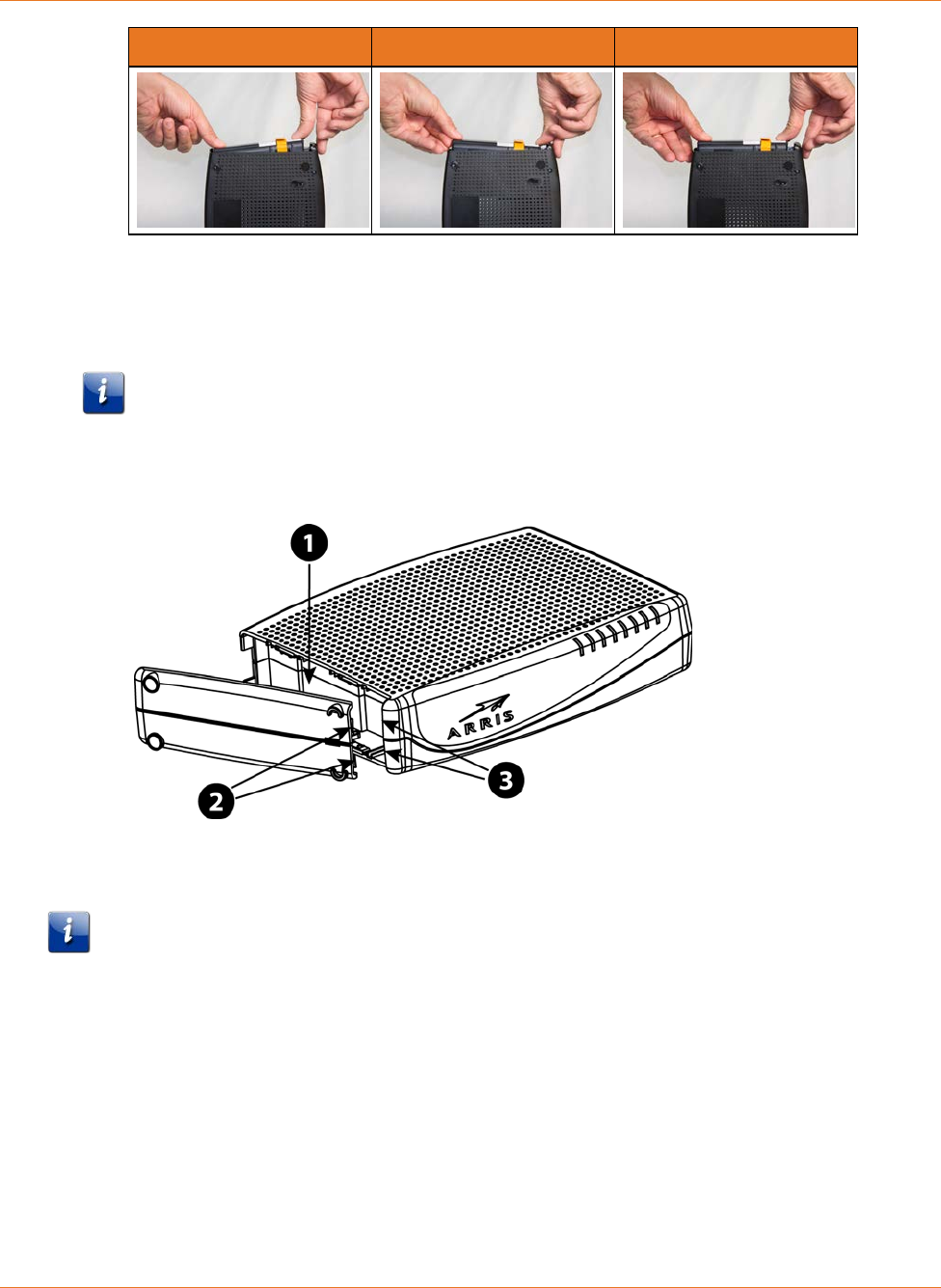
2. Hold the battery pack so that the guides on the battery align with the slots on the
Telephony Modem and slide the battery into the bay.
1 - Battery Slots
2 - Battery Guides
3 - Battery Pull Strap
Note: Batteries will not insert completely into the Telephony Modem if not oriented
correctly. The battery should slide into the bay without significant force. Line up the slots
in the battery bay with the guides on the battery and apply even pressure on both ends
of the battery.
Chapter 4: Battery Installation and Removal
STANDARD PN 365-095-31188 x.1 TM822R DOCSIS® 3.0 Telephony Modem For XFINITY Customers User Guide
© 2016 ARRIS Enterprises LLC. All Rights Reserved. 20
WRONG WRONG RIGHT
3. Push the battery pack into the bay until it latches into place. If you are taking the
battery out of the Telephony Modem, use the battery pull strap to dislodge the
battery.
Note: The Telephony Modem will not begin operating until you apply AC power.
4. Replace the door. To do so, place the tabs of the battery door into the slot inside the
Telephony Modem battery compartment. Rotate the door toward the front of the
Telephony Modem until the latch snaps back into place.
1 - Battery Compartment
2 - Hinge Tabs
3 - Receiver Slots
Note: Telephony Modems use a Lithium-Ion battery pack. Please recycle or dispose of the
battery responsibly and in accordance with local ordinances.
Maximum Battery Installation and Replacement
This model of the Telephony Modem has the ability to provide continued telephone service
during power outages. The battery backup is not intended to take the place of AC power.
Use this procedure to install and to replace the backup battery.
Chapter 4: Battery Installation and Removal
STANDARD PN 365-095-31188 x.1 TM822R DOCSIS® 3.0 Telephony Modem For XFINITY Customers User Guide
© 2016 ARRIS Enterprises LLC. All Rights Reserved. 21
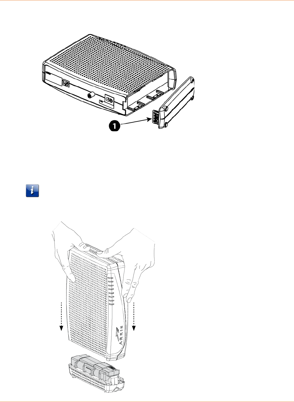
1. Press down and pull back on the latch holding the battery door (on the bottom of the
Telephony Modem). Pull the door toward you. Set the door aside in a safe place.
1 - Latch End
2. Place the battery on a firm horizontal surface.
3. Position the Telephony Modem over the battery, aligning the slots on the battery bay
with the tabs on the battery. Push straight down on the Telephony Modem until the
battery latch clicks into place.
Note: You may need to push down gently on the front of the Telephony Modem to latch
the battery into place. The Telephony Modem will not begin operating until you apply AC
power.

Chapter 4: Battery Installation and Removal
STANDARD PN 365-095-31188 x.1 TM822R DOCSIS® 3.0 Telephony Modem For XFINITY Customers User Guide
© 2016 ARRIS Enterprises LLC. All Rights Reserved. 22
4. To remove the battery, grasp the battery and pull back on the latch at the front of the
battery. Then gently rock the battery out of the bay.
Note: Telephony Modems use a Lithium-Ion battery pack. Please recycle or dispose of the
battery responsibly and in accordance with local ordinances.
Battery Usage and Storage Conditions
The life expectancy of your battery should be several years, provided that it was
purchased from an approved source.
Your battery goes through a calibration procedure when it is first installed or replaced.
This procedure can take up to 72 hours to complete and is repeated every six months.
If your battery becomes fully drained during a power outage, the calibration procedure
will need to be repeated.
Your battery should be installed in your Telephony Modem and kept there at all times.
Do not store the battery separately from the Telephony Modem for any prolonged
period of time.
Battery Disposal Guidelines
To ensure compliance with current and future rechargeable battery take-back laws, ARRIS
has joined Call2Recycle, a collection program for rechargeable batteries throughout North
America. US and Canadian customers should visit http://www.call2recycle.org to properly
recycle your lithium-ion battery backup units (BBUs).
Getting Battery Status
To assess whether the battery needs to be replaced, the Telephony Modem charges,
discharges, and recharges the battery pack as part of a battery test. The Telephony Modem
re-tests the battery periodically afterwards, usually every 180 days. The Battery LED and the
Registration Status screen indicate the status of the battery.
To view the Registration Status screen:
1. Using a web browser, access http://192.168.100.1/ You may have to manually adjust
your computer's IP address to (for example) 192.168.100.6 to access the HSD pages.
2. Click the CM State link below the ARRIS banner.
3. Scroll down, if necessary, to see the Power Supply Telemetry and Battery Test State
information at the bottom of the page. The expected states are:
• Power Supply Telemetry: TELEMETRY NORMAL
• Battery Test State: Not Currently Under Battery Test

STANDARD PN 365-095-31188 x.1 TM822R DOCSIS® 3.0 Telephony Modem For XFINITY Customers User Guide
© 2016 ARRIS Enterprises LLC. All Rights Reserved. 23
Chapter 5
Installing and Connecting your Telephony
Modem
Before you start, make sure that:
You have contacted your service provider and verified that they provide data and
telephone service using standard DOCSIS technology.
You have all the Items You Need (page 9).
Cable, phone, and power outlets are available near the computer. If a cable outlet is not
conveniently located, your service provider can install a new one.
If you have ordered service, your service provider should configure the Telephony Modem
automatically. You need only follow the instructions in this section to install and connect the
Telephony Modem.
CAUTION
Risk of equipment damage
Only qualified installation technicians should connect the Telephony Modem to house
wiring. Incumbent telephone service must be physically disconnected at the outside
interface box before making any connections.
Chapter 5: Installing and Connecting your Telephony Modem
STANDARD PN 365-095-31188 x.1 TM822R DOCSIS® 3.0 Telephony Modem For XFINITY Customers User Guide
© 2016 ARRIS Enterprises LLC. All Rights Reserved. 24
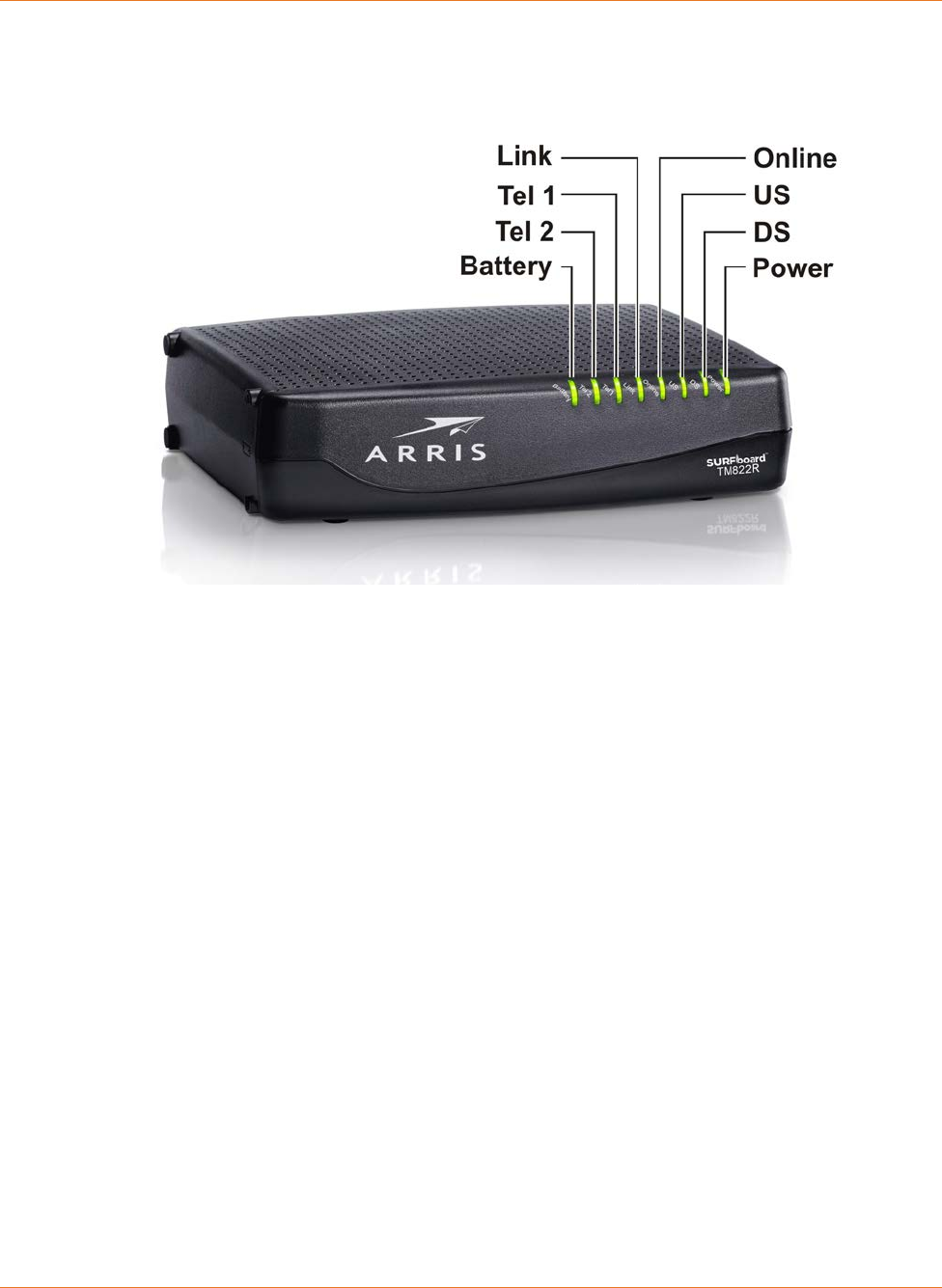
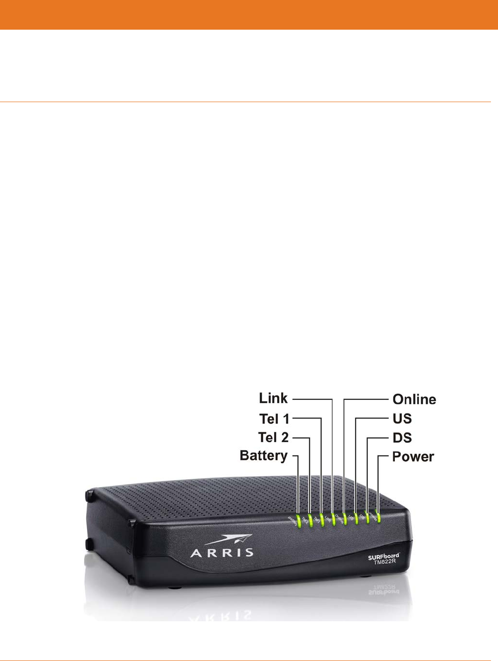
Front Panel
The front of the Telephony Modem has the following indicators.
Battery: indicates the battery status.
Tel 2: indicates the status of telephone line 2.
Tel 1: indicates the status of telephone line 1.
Link: indicates Ethernet connectivity between the Telephony Modem and computer. it may
be yellow or green to indicate the connection speed.
Online: indicates internet data transmission status.
US: indicates upstream connectivity. It may be yellow or green to indicate the connection
speed.
DS: indicates downstream connectivity. It may be yellow or green to indicate the connection
speed.
Power: indicates whether AC power is available to the unit.
Chapter 5: Installing and Connecting your Telephony Modem
STANDARD PN 365-095-31188 x.1 TM822R DOCSIS® 3.0 Telephony Modem For XFINITY Customers User Guide
© 2016 ARRIS Enterprises LLC. All Rights Reserved. 25
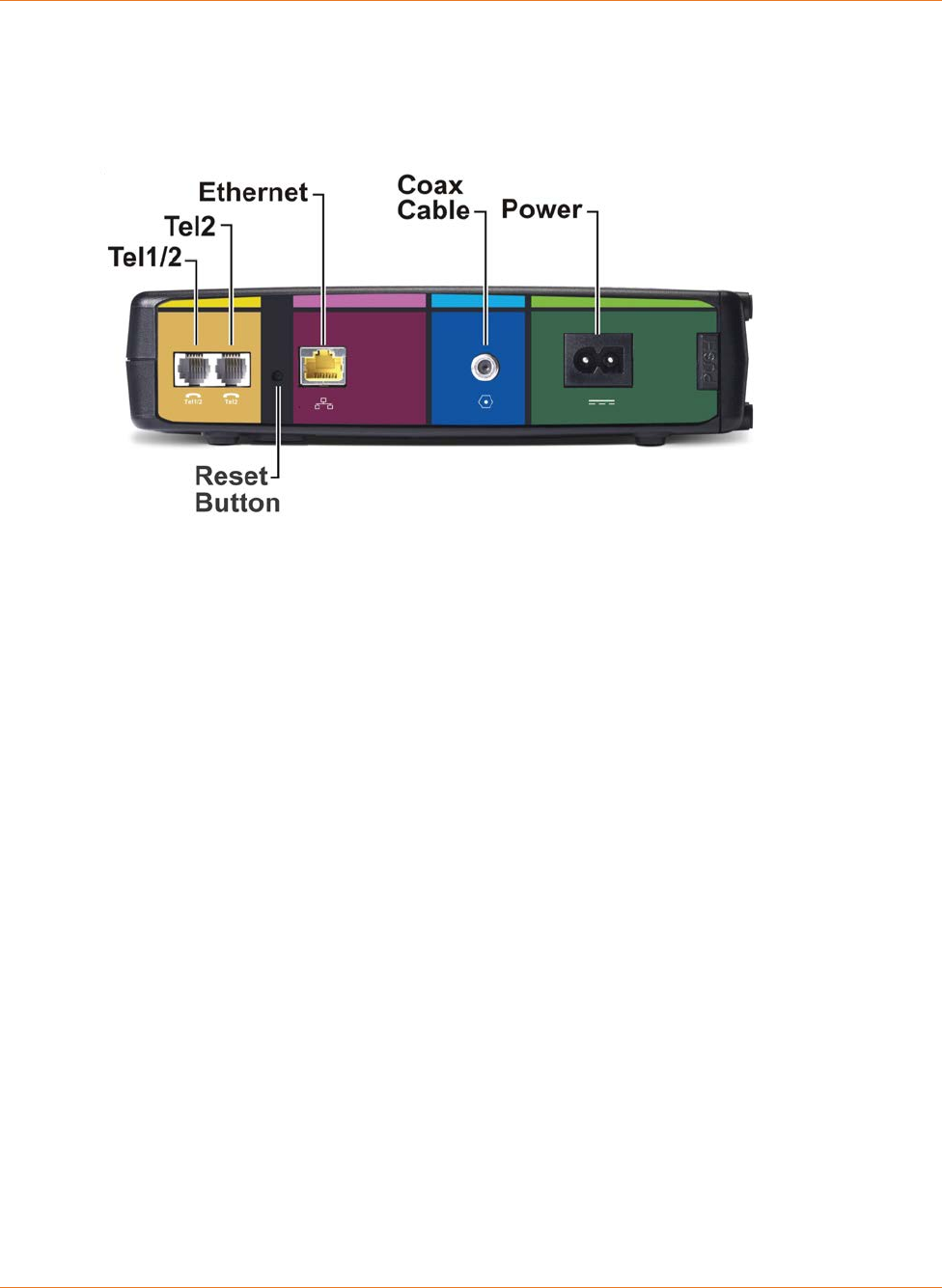
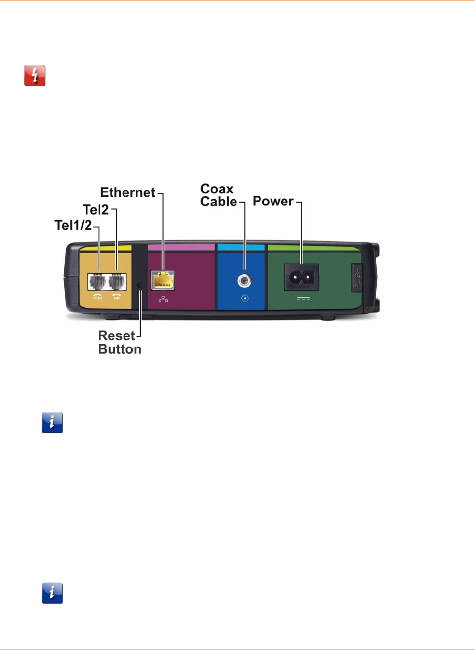
Rear Panel
The rear of the Telephony Modem has the following connectors and controls.
Tel 1/2: connector for the first phone line (or both lines of a 2-line phone).
Tel 2: connector for the second phone line.
Ethernet: connector for use with a computer LAN port.
Coax Cable: connector for the coaxial cable.
Power: connector for the power cord.
Reset button: resets the Telephony Modem as if you power cycled the unit. Use a pointed
non-metallic object to press this button.
Selecting an Installation Location
There are a number of factors to consider when choosing a location to install your Telephony
Modem:
Is an AC outlet available nearby? For best results, the outlet should not be switched and
should be close enough to the Telephony Modem that extension cords are not required.
Is a cable jack available? For best performance, keep the number of splitters between
the jack and cable drop to a minimum. Each splitter attenuates (reduces) the signal
available to the Telephony Modem. A large number of splitters can slow down the
Internet connection and even affect your telephone service.
Can you easily run cables between the Telephony Modem’s location and the phones?
If you are connecting devices to an Ethernet port, can you easily run cables between the
Telephony Modem’s location and those devices?

Chapter 5: Installing and Connecting your Telephony Modem
STANDARD PN 365-095-31188 x.1 TM822R DOCSIS® 3.0 Telephony Modem For XFINITY Customers User Guide
© 2016 ARRIS Enterprises LLC. All Rights Reserved. 26
If you want to mount the Telephony Modem on a wall, does the location provide a solid
surface for secure attachment? For best results when mounting the Telephony Modem
on drywall, position the Telephony Modem so at least one of the screws are fastened to
a stud. This may prevent the Telephony Modem from pulling out of the wall in the
future.
If you want to install the Telephony Modem on a desktop, is there enough space on
either side to keep the vents clear? Blocking the vents may cause overheating.
Mounting the Telephony Modem
You can either mount the Telephony Modem on a wall or place it on a desktop. For wall-
mount applications, you can mount the Telephony Modem with the indicators facing upward
(vertical) or to the side (horizontal).
Tools and Materials
For wall-mounted installations, make sure you have the following tools and materials before
proceeding:
for mounting on drywall: Two 1/4” (6mm) drywall anchors (not included), two #6 x 1.5”
(38.1 mm) self-tapping panhead screws (not included), and a drill with 1/4” (6mm) bit
(not included).
for mounting on plywood or studs: two #6 x 1.5” (38.1 mm) self-tapping panhead wood
screws (not included).
screwdriver (flat-blade or Phillips, depending on what kind of screws you use).
wall-mount template (included with the Telephony Modem Quick Installation Guide.
transparent tape: for temporarily securing the mounting template to the wall (not
included).
Location
Always position the Telephony Modem:
within reach of an AC outlet. The power cord must reach the outlet without stretching
and without adding extension cords.
near a cable outlet (to avoid long cable runs).
Wall Mounting Instructions
Note: When mounting the Telephony Modem on drywall, try to position the Telephony
Modem so at least one of the screws is fastened to a stud. This may prevent the Telephony
Modem from pulling out of the wall in the future. To prevent overheating of the Telephony
Modem, do not block the ventilation holes on the sides of the unit.
Chapter 5: Installing and Connecting your Telephony Modem
STANDARD PN 365-095-31188 x.1 TM822R DOCSIS® 3.0 Telephony Modem For XFINITY Customers User Guide
© 2016 ARRIS Enterprises LLC. All Rights Reserved. 27
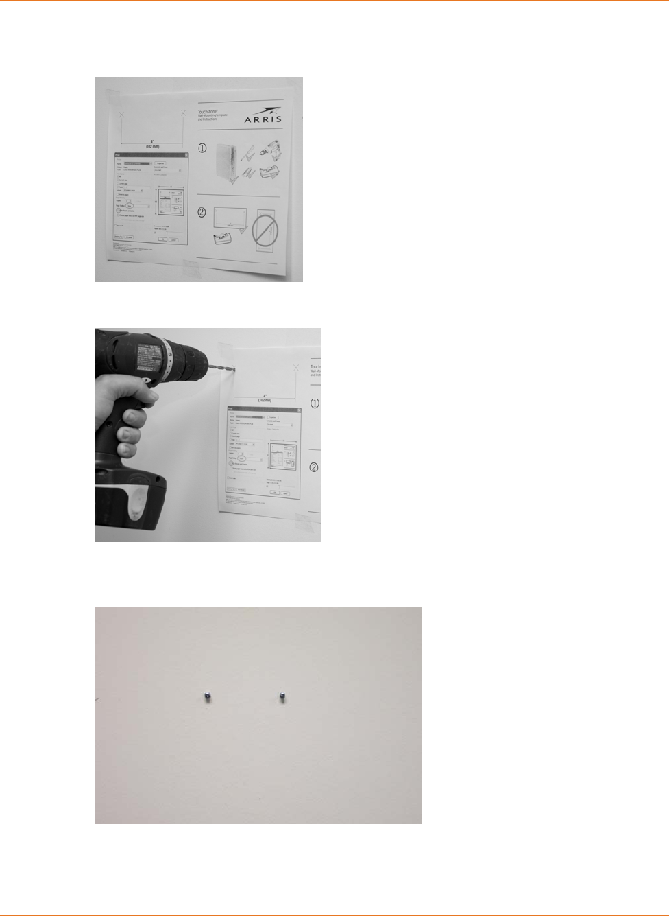
1. Position the mounting template on the surface where you intend to mount the
Telephony Modem and sercure in place with transparent tape.
2. Drill holes through the template in the specified locations for the mounting screws. After
drilling holes, remove the template from the service.
3. If using drywall anchors, set them into the wall. Then, drive the screws into the wall
leaving a gap of about 1/8” (3 mm) between the screw head and the wall. If not using
anchors, just drive the screws.
Chapter 5: Installing and Connecting your Telephony Modem
STANDARD PN 365-095-31188 x.1 TM822R DOCSIS® 3.0 Telephony Modem For XFINITY Customers User Guide
© 2016 ARRIS Enterprises LLC. All Rights Reserved. 28
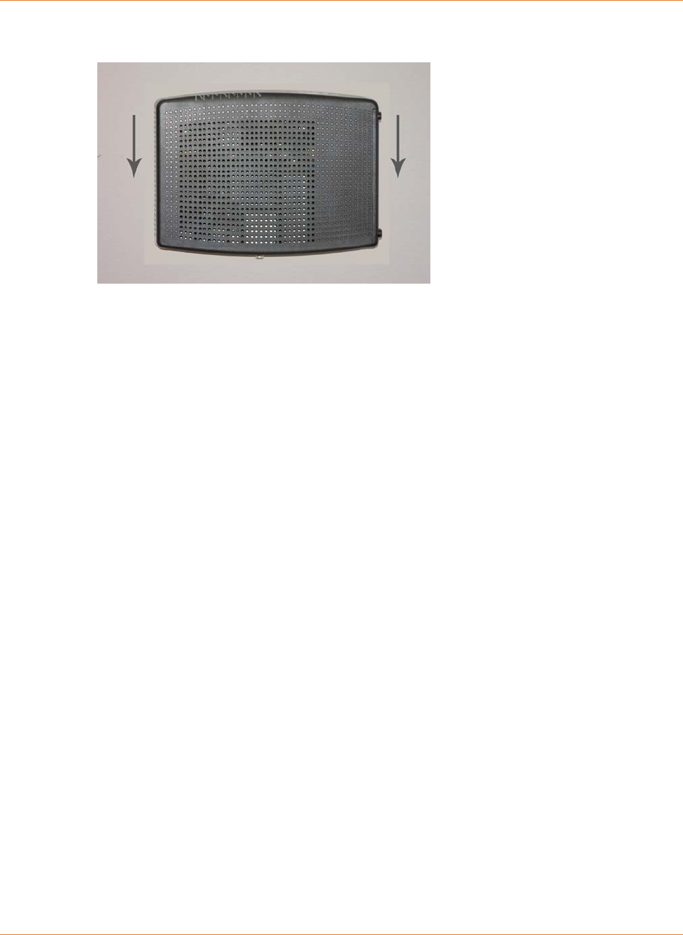
4. Slip both mounting slots in the back of the Telephony Modem over the screws, then slide
the case down until the narrow end of the keyhole slot contacts the screw shaft.
5. Proceed to Connecting the Telephony Modem.
Desktop Mounting Instructions
1. Position the Telephony Modem so that:
• air flows freely around it
• the back faces the nearest wall
• it will not fall to the floor if bumped or moved
• the ventilation holes on the sides of the unit are not blocked
2. Proceed to Connecting the Telephony Modem.
Chapter 5: Installing and Connecting your Telephony Modem
STANDARD PN 365-095-31188 x.1 TM822R DOCSIS® 3.0 Telephony Modem For XFINITY Customers User Guide
© 2016 ARRIS Enterprises LLC. All Rights Reserved. 29
Connecting the Telephony Modem
WARNING
Risk of injury or equipment damage
Connecting the Telephony Modem to the home’s existing telephone wiring should only be
performed by a professional installer. Physical connections to the previous telephone
provider must be removed and the wiring must be checked; there must not be any voltage.
Cancelation of telephone service is not adequate. Failure to do so may result in loss of
service and/or permanent damage to the Telephony Modem.
1. Connect one end of the coax cable to the cable outlet or splitter, and the other end to
the Telephony Modem’s Cable connector. Tighten the connections by hand, then tighten
an additional 1/8 turn with a wrench.
Note: For best performance, use high-quality coax cable and minimize or eliminate
splitters between the cable jack and the Telephony Modem.
2. Insert the plug from the power cord into the Power connector on the back of the
Telephony Modem and insert the power cord into a convenient AC outlet.
The Power light on the front of the Telephony Modem lights up, then flashes once (refer
to the LED tables shown in Using the Telephony Modem (page 34)). See Troubleshooting
(page 38) if the Power light does not turn on.
3. Connect one end of the Ethernet cable to the Ethernet port on the back of the Telephony
Modem, and the other end to the Ethernet port on a computer, hub, or broadband
router.
Note: If you are connecting to a computer, use the Ethernet cable included in the
Telephony Modem package.

Chapter 5: Installing and Connecting your Telephony Modem
STANDARD PN 365-095-31188 x.1 TM822R DOCSIS® 3.0 Telephony Modem For XFINITY Customers User Guide
© 2016 ARRIS Enterprises LLC. All Rights Reserved. 30
4. Connect one end of the telephone cable to the telephone port on the back of the
Telephony Modem. Connect the other end to the telephone.

STANDARD PN 365-095-31188 x.1 TM822R DOCSIS® 3.0 Telephony Modem For XFINITY Customers User Guide
© 2016 ARRIS Enterprises LLC. All Rights Reserved. 31
Chapter 6
Configuring Your Ethernet Connection
If your computer is equipped with a LAN card providing an Ethernet connection, you may
have to configure your computer’s TCP/IP settings. The steps that follow will guide you
through setting your computer’s TCP/IP settings to work with the Telephony Modem.
Requirements
Make sure you have the following before attempting to configure your Ethernet connection:
Computer with Ethernet interface.
Ethernet cable (supplied).
IP address, subnet, gateway, and DNS information for installations not using DHCP.
How to use this Chapter
The following list shows the procedures for modifying the TCP/IP settings on the computer.
The procedure is slightly different depending on the operating system that you are using.
Please ensure you are using the correct steps for the operating system on your computer.
Follow the links below for instructions to configure your Ethernet connection on your
operating system.
TCP/IP Configuration for Windows Vista (page 31)
TCP/IP Configuration for Windows 7, Windows 8, or Windows 10 (page 32)
TCP/IP Configuration for Mac OS X (page 32)
TCP/IP Configuration for Windows Vista
Follow these steps to configure the Ethernet interface on a Windows Vista operating system.
1. Open the Vista Control Panel.
2. Double-click Network and Sharing Center to display the Network and Sharing Center
Window.
3. Click Manage network connections. If prompted for a connection, choose Local Area
Connection.
The Network Connections window displays.

Chapter 6: Configuring Your Ethernet Connection
STANDARD PN 365-095-31188 x.1 TM822R DOCSIS® 3.0 Telephony Modem For XFINITY Customers User Guide
© 2016 ARRIS Enterprises LLC. All Rights Reserved. 32
4. Double-click the Local Area Connection to open the Properties window:
Note: If Windows requests permission to continue, click Continue.
5. Double-click Internet Protocol Version 4 (TCP/IPv4) to configure TCP/IPv4.
Note: If your cable provider requires TCP/IP version 6, double-click Internet Protocol
Version 6 (TCP/IPv6) to configure TCP/IPv6.
The TCP/IP properties window for the version you selected displays.
6. For either TCP/IPv4 or TCP/IPv6, select Obtain an IP address automatically and Obtain
DNS server address automatically, unless instructed otherwise by your cable provider.
7. Click OK to accept the new settings and close the Properties window.
TCP/IP Configuration for Windows 7, Windows 8,
or Windows 10
Follow these steps to configure the Ethernet interface on a Windows 7, Windows 8, or
Windows 10 operating system.
1. Click the Start menu and type network and sharing into the Search box.
2. Select Network and Sharing Center when it appears.
3. Click Change adapter settings from the left-side menu.
4. Right-click on your local area connection icon and select Properties to open the
Properties window.
5. Select Internet Protocol Version 4 (TCP/IPv4) and click Properties to configure TCP/IPv4.
Note: If your cable provider requires TCP/IP version 6, select Internet Protocol Version 6
(TCP/IPv6) and click Properties to configure TCP/IPv6.
The TCP/IP properties window for the version you selected displays.
6. For either TCP/IPv4 or TCP/IPv6, select Obtain an IP address automatically and Obtain
DNS server address automatically, unless instructed otherwise by your cable provider.
7. Click OK to accept the new settings and close the Properties window. Then click Close to
back out of the remaining setup screens.
TCP/IP Configuration for Mac OS X
Follow these steps to configure the Ethernet interface on a Mac OS X operating system.
1. Open System Preferences, either by choosing System Preferences from the Apple menu
or by clicking the System Preferences icon in the dock.

Chapter 6: Configuring Your Ethernet Connection
STANDARD PN 365-095-31188 x.1 TM822R DOCSIS® 3.0 Telephony Modem For XFINITY Customers User Guide
© 2016 ARRIS Enterprises LLC. All Rights Reserved. 33
2. Click the Network icon.
3. Choose Automatic from the Location drop-down menu, and Built-in Ethernet from the
Show menu.
4. Choose the TCP/IP tab, if necessary.
If you are using TCP/IPv4, go to step 5.
If your cable provider requires TCP/IPv6, go to step 8.
5. Choose Using DHCP from the Configure IPv4 menu.
6. If necessary, click the Renew DHCP Lease button.
7. Close the System Properties application.
TCP/IPv4 configuration is completed.
8. If you are using TCP/IPv6, click Configure IPv6 near the bottom of the previous window.
9. Choose Automatically from the Configure IPv6 drop-down menu and click OK.
10. Close the System Properties application.
STANDARD PN 365-095-31188 x.1 TM822R DOCSIS® 3.0 Telephony Modem For XFINITY Customers User Guide
© 2016 ARRIS Enterprises LLC. All Rights Reserved. 34
Chapter 7
Using the Telephony Modem
This chapter describes the controls and features available on the Telephony Modem, and
covers basic troubleshooting procedures.
Setting up Your Computer to Use the Telephony Modem (page 34)
Indicator Lights for the TM822R (page 34)
Using the Reset Button (page 37)
Booting from Battery (page 37)
Setting up Your Computer to Use the Telephony
Modem
Follow the instructions in the information packet supplied by your service provider. Contact
your service provider if you need help setting up your computer.
Indicator Lights for the TM822R
The Telephony Modem has LED indicator lights to assist in troubleshooting.

Chapter 7: Using the Telephony Modem
STANDARD PN 365-095-31188 x.1 TM822R DOCSIS® 3.0 Telephony Modem For XFINITY Customers User Guide
© 2016 ARRIS Enterprises LLC. All Rights Reserved. 35
Battery Mismatch
If the Telephony Modem alternates flashing the Battery light and all other lights, the
installed battery is incompatible with the Telephony Modem. Remove the battery and install
one of the batteries described in Battery Installation and Removal (page 15).
Wiring Problems
If the Telephony Modem begins flashing all its lights for more than 10 seconds, this indicates
a problem with the telephone wiring — the red and green wires may be shorted (touching),
or there may be undesired voltage on the lines. If this pattern persists for more than 10
seconds, disconnect the telephone lines from the Telephony Modem, then call a wiring
technician for assistance.
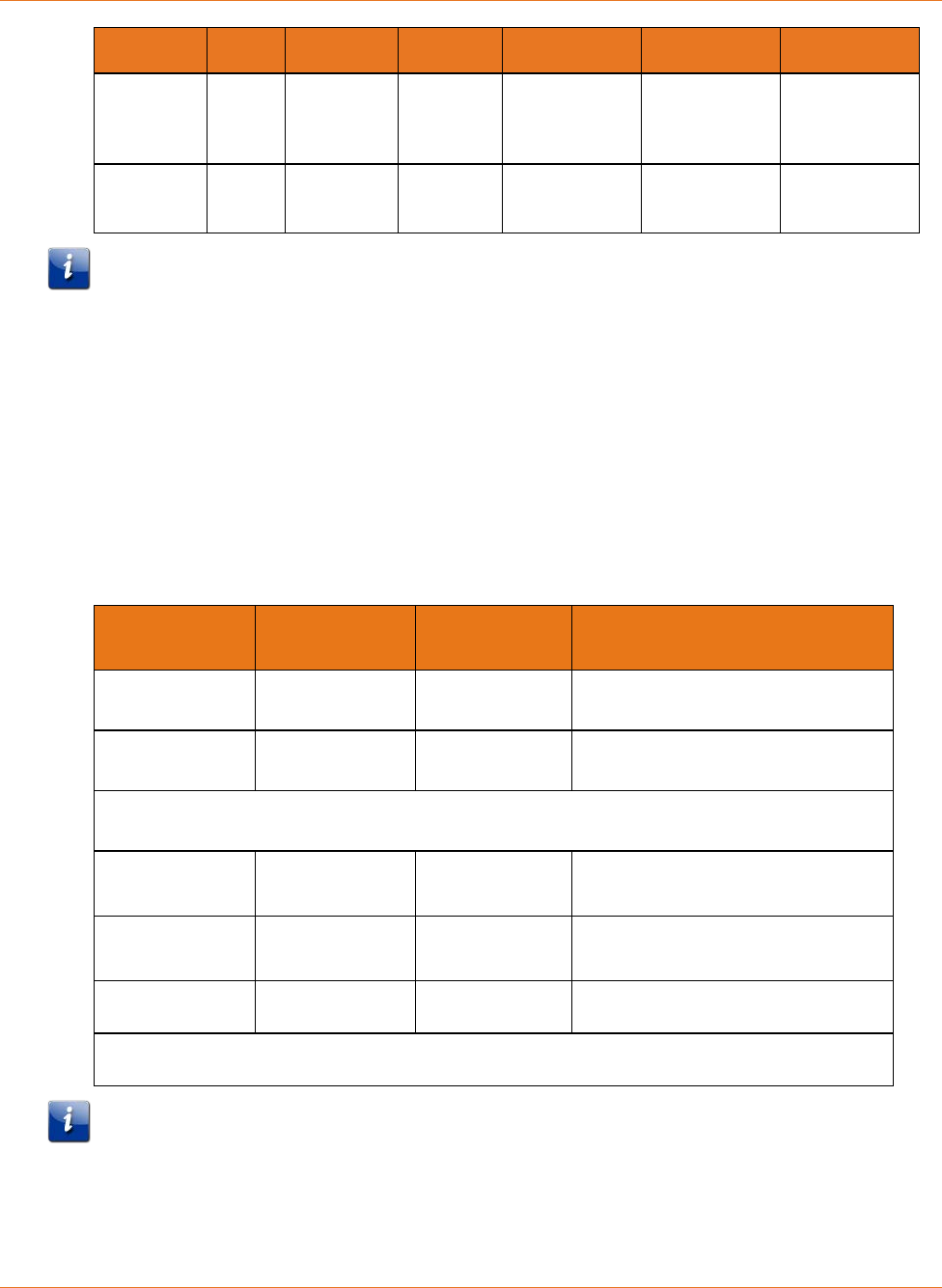
Patterns: Normal Operation
The following table shows light patterns during normal operation.
Mode Power US/DS Online Link Tel 1 / Tel 2 Battery
AC Power On Yellow1 =
Connected
to the
Internet
(high
speed)
Green1 =
Connected
to the
Internet
(ultra-high
speed)
Flash =
Not
connected
to the
Internet
On =
Internet
available
Off =
Internet
not
available
Yellow1 =
Connected to
the Internet
(high speed)
Green1 =
Connected to
the Internet
(ultra-high
speed)
Flash = Not
connected to
the Internet
Off =
Computer not
connected
On = On-hook
Flash = Off-
hook
Off = disabled
On = Battery
good or low
Off = Battery
missing or
MTA not
registered
Flash =
Battery bad
No AC
Power
Battery
Installed
Flash Off Off Off On = On-hook
Flash = Off-
hook
Off = disabled
Off = Battery
power
Flash =
Battery bad
or low
Chapter 7: Using the Telephony Modem
STANDARD PN 365-095-31188 x.1 TM822R DOCSIS® 3.0 Telephony Modem For XFINITY Customers User Guide
© 2016 ARRIS Enterprises LLC. All Rights Reserved. 36
Mode Power US/DS Online Link Tel 1 / Tel 2 Battery
No AC
Power
No Battery
Off Off Off Off Off Off
Firmware
Upgrade
On Flash On (normal
operation)
(normal
operation)
(normal
operation)
Note 1: Your service provider may configure the Telephony Modem to always display the DS,
US, and Link indicators in green regardless of the connection speed or swap the meaning
(speed indication) of yellow and green.
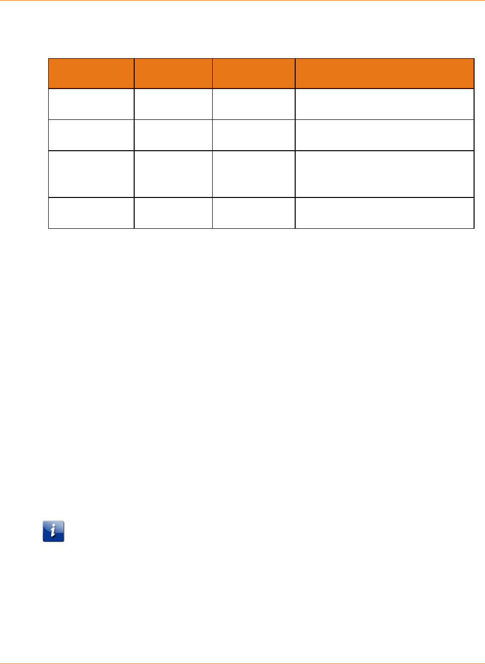
Patterns: Startup Sequence
The following tables show the Telephony Modem light patterns during each phase of the
startup sequence. There are two phases of startup; the telephony phase and the cable
modem phase. Both are outlined below.
Telephony Startup Sequence
Power, US/DS,
Online
Telephone 1 Telephone 2 Description
Off Off Off No power to modem
Flash Flash Flash Power-on Self Test
See Cable Modem Startup Sequence (page 37)
On Flash Off Retrieving telephone network
information
On Off Flash Retrieving telephone network
information
On Flash Flash Activating telephone service
Normal Operation
Note: The US/DS indicator flashes yellow during startup and turns green if the Telephony
Modem establishes an ultra-high speed connection. For some service providers, these colors
may be reversed.
Chapter 7: Using the Telephony Modem
STANDARD PN 365-095-31188 x.1 TM822R DOCSIS® 3.0 Telephony Modem For XFINITY Customers User Guide
© 2016 ARRIS Enterprises LLC. All Rights Reserved. 37
Cable Modem Startup Sequence
DS US Online Description
Flash Off Off Downstream search
On Flash Off Downstream found; upstream search
On On Flash Downstream and Upstream found;
retrieving setup information from
service provider
On On On Ready for service
Using the Reset Button
Use the Reset button, on the back of the Telephony Modem, to reset the modem and
perform initialization as if you power cycled the unit. You may need to reset the Telephony
Modem if you are having problems connecting to the Internet. Using this button will be rare.
Use a pointed non-metallic object to press this button. The Reset button is recessed to
prevent accidental resets.
Booting from Battery
The TM822R supports a “Boot from Battery” feature that allows the Telephony Modem to
provide continued telephone service during power outages.
To start the TM822R from its battery, follow these steps:
1. If a battery is already installed in the Telephony Modem, remove it.
2. Re-insert the battery into the Telephony Modem. See Battery Installation and Removal
(page 15) for details.
3. Press the Reset button; the Power light should turn on immediately.
Note: If the Telephony Modem does not turn on, the battery may not be charged.

STANDARD PN 365-095-31188 x.1 TM822R DOCSIS® 3.0 Telephony Modem For XFINITY Customers User Guide
© 2016 ARRIS Enterprises LLC. All Rights Reserved. 38
Chapter 8
Troubleshooting
The Telephony Modem is plugged in, but the
Power light is Off
Check all power connections. Is the power cord plugged in firmly at both ends?
If you plugged the power cord into a power strip, make sure the strip is switched on.
Try to plug the power cord into a different outlet. If the outlet is controlled by a wall switch,
make sure the switch is on.
Finally, check the fuse or circuit breaker panel.
I'm not getting on the Internet
It may take over 30 minutes to establish a connection the first time you power up your
Telephony Modem, especially when many people are online. Always leave your Telephony
Modem plugged into AC power and connected to the cable system.
Check the front panel lights:
The Power and Online lights should be on.
The Link light should either be on or blinking.
If the Power light blinks for more than 30 minutes, call your service provider for
assistance.
Check your cable connections. Connectors should be tight. The coax cable should not be
pinched, kinked, or bent sharply—any of these can cause a break or short in the cable (you
may have to replace the cable). If you have one or more splitters between the Telephony
Modem and CATV outlet, remove the splitters and connect the Telephony Modem directly
to the outlet.
Proceed to the Ethernet solution if necessary.
I'm not getting on the Internet (Ethernet)
If you are using a hub, is the hub turned on?
Are you using the right type of Ethernet cable? Use the supplied cable for direct connection
to a computer; use a cross-over cable for connection to a hub.

Chapter 8: Troubleshooting
STANDARD PN 365-095-31188 x.1 TM822R DOCSIS® 3.0 Telephony Modem For XFINITY Customers User Guide
© 2016 ARRIS Enterprises LLC. All Rights Reserved. 39
Press the Reset button on the back of the Telephony Modem.
I can get on the Internet, but everything is slow
If the Web site you are visiting is very popular, that site may be having trouble servicing all
the requests. If other sites download quickly, wait for a few minutes and try again. Usage
during peak hours may also affect the connection speed.
Other communications on the LAN may slow down the connection.
I don't have a dial tone when I pick up the phone
- why?
In order for telephone service to be functional on the Telephony Modem, telephone service
must have been purchased from the service provider and configured on your Telephony
Modem. The following steps should help in identifying the source of the problem.
1. Is the Power LED lit?
• If not, check to make sure the Telephony Modem is plugged in and the outlet has
power. Use only the external AC power adapter (if provided) and power cord
included with the equipment.
• If the LED is lit, go to the next step.
2. Is the Online LED lit?
• If not, check the coax connection at the Telephony Modem and the wall. Ensure they
are connected and tight. If they are and you do not have dial tone, contact your
service provider.
• If the Online LED is lit, go to the next step.
3. Is the Telephone (Tel 1 or Tel 2) LED lit?
• If not, phone service has not been set up on that line. Contact your service provider.
• If it is blinking, there is a phone off hook somewhere in the house. Find that phone
and hang it up.
• If it is lit, go to the next step.
4. Is the phone plugged directly into the Telephony Modem?
• Make sure the phone is plugged into the port on the back of the Telephony Modem
labeled “Tel 1” for line 1, and “Tel 2” for line 2.
• If so, try a different phone. Make sure the new phone is a working phone.
• If a known good phone is used and you still don’t have dial tone, try a different
phone cable. If a new phone and cable do not restore dial tone, call your service
provider.
5. Is the Telephony Modem plugged into a wall outlet?

Chapter 8: Troubleshooting
STANDARD PN 365-095-31188 x.1 TM822R DOCSIS® 3.0 Telephony Modem For XFINITY Customers User Guide
© 2016 ARRIS Enterprises LLC. All Rights Reserved. 40
• If so, unplug the phone connector at the back of the Telephony Modem and plug in a
known working phone. If you now have dial tone, the problem is with the house
wiring. Contact your service provider or a qualified wiring technician to correct the
house wiring. If you still do not have dial tone, contact your service provider.

STANDARD PN 365-095-31188 x.1 TM822R DOCSIS® 3.0 Telephony Modem For XFINITY Customers User Guide
© 2016 ARRIS Enterprises LLC. All Rights Reserved. 41
Glossary
A
Amp-Hour
A measure of battery capacity. For
example, a 1.0Ah battery can nominally
supply one Ampere of current for one
hour.
C
Category 5e (Cat5e)
A high-quality type of cable, used for
gigabit Ethernet (1000BaseT) connections.
When purchasing Ethernet cables, always
look for Category 5e cable.
Coaxial cable (coax)
A thin wire, used to connect your television
and Telephony Modem to the cable TV
system. You can buy coax from any
electronics retailer and many discount
stores.
CPE
Customer Premise Equipment. This is the
equipment that is plugged in to the
Telephony Modem; typically a computer or
hub.
Cross-over
An Ethernet cable used to connect two
hubs (or a hub and a cable modem)
together. Also, some Ethernet hubs may
have built-in cross-over on one or more
ports (which eliminates the need for a
cross-over cable).
D
DHCP
Dynamic Host Configuration Protocol. An
IP protocol used to provide an IP address
and location of services (such as DNS and
TFTP) needed by a device connecting to
the network. DHCP allows the cable
company to configure your computer’s
networking software for you.
DNS
Domain Name Service (Server). An IP
service that associates a domain name
(such as www.example.com) with an IP
address.
DOCSIS
Data Over Cable System Interface
Specification. The interoperability
standards used for data communications
equipment on an HFC network.
Downstream
In an HFC network, the direction from the
head-end to the subscriber. Some older
cable documentation may refer to this as
the forward path.
E
EMTA
Embedded Multimedia Terminal Adapter.
An MTA device that is integrated with a
cable modem.
Ethernet
A standard method of connecting two or
more computers into a Local Area Network
(LAN).

STANDARD PN 365-095-31188 x.1 TM822R DOCSIS® 3.0 Telephony Modem For XFINITY Customers User Guide
© 2016 ARRIS Enterprises LLC. All Rights Reserved. 42
Event
An informational message used for
monitoring network status.
F
F-connector
The type of connector used on coax cable.
There are two common types of F-
connector, slip-on and screw-on. Use coax
with screw-on connectors for connecting
your Telephony Modem.
Firewall
A hardware or software device that
prevents unauthorized access to a private
network from the Internet. The TM822R
provides a built-in firewall.
G
Gateway
The device, usually a router, that connects
devices on a given IP subnet to other IP
subnets.
H
Headend
The “central office” in an HFC network. The
headend houses both video and data
equipment. In larger cable networks, a
“master” headend often feeds several
“remote” headends to provide distributed
services.
HTTP
HyperText Transfer Protocol.
Hub
A box with several Ethernet connectors.
Ethernet hubs provide a common point of
contact for all connected devices.
I
IP address
A number assigned to your computer by
your service provider, used to identify your
computer to other systems on the
Internet.
ISDN
Integrated Services Digital Network. A
digital telephony standard that provides
communication speeds about twice as fast
as standard dialup.
L
LAN
Local Area Network. A network that allows
computers in a single location (such as a
building) to communicate with one
another.
LED
Light Emitting Diode. A semi-conductor
diode that emits light when current is
passed through it.
M
MAC address
A number that uniquely identifies any
device connected to a network. Your
service provider uses your Telephony
Modem’s MAC address to authorize access
to the Internet. The MAC address is printed
on a label on the bottom of your
Telephony Modem.
P
Protocol
A set of rules and formats that determines
the communication behavior of network
entities at a given layer.
Proxy
A device or program that stands in
between a server (for example, a web site)
and a client (your browser), providing a
way to relieve some of the burden from
the server. For example, your service
provider may have a web proxy that keeps
copies of popular web pages; the proxy can
send you those pages instead of fetching
them directly from the web site, resulting
in faster page loading and less network
congestion.
R
RF
Abbreviation for Radio Frequency. Some
literature refers to coax as “RF cable” and
the connectors as “RF connectors.”
RJ-11
A standard 2-conductor modular
connector, commonly used in North
America for connecting telephones.
RJ-45
A standard 8-conductor modular
connector, commonly used on Ethernet
cable. An RJ-45 connector looks like a wide
RJ-11 (telephone) connector.
S
Splitter
A small box with three cable connectors:
one input and two outputs. You may need
a splitter if you have a TV already
connected to the cable outlet that you
want to use for your Telephony Modem.
You can buy a splitter from any electronics
retailer and most discount stores.
Switched outlet
A power outlet that may be turned on and
off using a wall switch. Usually intended
for lamps. Avoid plugging your computer
or Telephony Modem into a switched
outlet to avoid disruptions.
T
TCP/IP
Transmission Control Protocol/Internet
Protocol. The protocols used to facilitate
communications across one or more
connected networks.
TDMA
Time Division Multiple Access. A method
used by DOCSIS-compliant cable modems
for sending upstream data with minimal
interference.
U
Upstream
The path from a subscriber device to the
headend. Some older cable documentation
may refer to this as the return path or
reverse path.

Corporate Headquarters
ARRIS · Suwanee · Georgia · 30024 · USA
T: 1-678-473-2000 F: 1-678-473-8470
www.arris.com
