Arris Touchstone Battery BPB026S (Orderable SKU: 794068) Reference Guide User Manual BPB026S: Quick Start
User Manual: Arris Touchstone Battery BPB026S (Orderable SKU: 794068) BPB026S: Quick Start Guide
Open the PDF directly: View PDF ![]() .
.
Page Count: 66
- Touchstone® Battery Reference Guide STANDARD 1.0
- Publication History
- About this Document
- Safety Considerations
- Core Functions
- System Performance
- Provisioning
- Troubleshooting
- Extended Outage Handling
- Appendix A: Ordering Codes

Touchstone
Battery Reference Guide
© 2008
-2016 ARRIS Enterprises LLC. All Rights Reserved.
STANDARD Revision 2.5
August 2016

Touchstone® Battery Reference Guide
STANDARD 1.0
ARRIS Copyrights and Trademarks
© 2008-2016 ARRIS Enterprises LLC. All Rights Reserved. No part of this publication may be
reproduced in any form or by any means or used to make any derivative work (such as
translation, transformation, or adaptation) without written permission from ARRIS
Enterprises LLC. (“ARRIS”). ARRIS reserves the right to revise this publication and to make
changes in content from time to time without obligation on the part of ARRIS to provide
notification of such revision or change.
ARRIS and the ARRIS logo are all trademarks of ARRIS Enterprises LLC. Other trademarks and
trade names may be used in this document to refer to either the entities claiming the marks
and the names of their products. ARRIS disclaims proprietary interest in the marks and
names of others.
ARRIS provides this guide without warranty of any kind, implied or expressed, including, but
not limited to, the implied warranties of merchantability and fitness for a particular purpose.
ARRIS may make improvements or changes in the product(s) described in this manual at any
time.
The capabilities, system requirements and/or compatibility with third-party products
described herein are subject to change without notice.
Publication History
August 2016
Release 2.5 Standard 1.0 version of this manual. New models: TM1602, TG1652, TG1682,
TG2472, TM3202. New compliance information.
April 2015
Release 2.4 Standard 1.0 version of this manual. New batteries, corrected hold-up time
tables.
June 2009
Release 2.0 Standard 1.0 version of this document.
July 2008
Release 1.0 Standard 1.0 version of this document.

STANDARD Revision 2.5 Touchstone Release 2.5 Reference Guide
© 2008-2016 ARRIS Enterprises LLC. All Rights Reserved. 3
Table of Contents
1. Publication History .................................................................................................. 2
2. About this Document .............................................................................................. 6
Audience ............................................................................................................................ 6
In this Document ............................................................................................................... 6
47 CFR 12.5 Compliance .................................................................................................... 6
3. Safety Considerations ............................................................................................. 8
Handling ............................................................................................................................. 8
Transportation ................................................................................................................... 8
Storage ............................................................................................................................... 9
Environmental ........................................................................................................... 9
Extended Storage ...................................................................................................... 9
Disposal .............................................................................................................................. 9
4. Core Functions ...................................................................................................... 11
Charger Initialization Times ............................................................................................. 11
Battery Gauge Calibration and Accuracy ......................................................................... 12
Scheduling and Maintenance .......................................................................................... 13
Booting from Battery (Model 6 and newer) .................................................................... 13
Specifications ................................................................................................................... 14
Replacing a Battery .......................................................................................................... 16
Installing or Replacing a 2-cell Battery ................................................................... 16
Installing or Replacing a 4-cell Battery ................................................................... 18
Installing or Replacing a 6-cell or 8-cell Battery (2- and 4-line modems) ............... 19
Installing or Replacing a 8-cell Battery (TM608) ..................................................... 21
5. System Performance ............................................................................................. 22
Typical Lifetimes .............................................................................................................. 22
Temperature vs. Battery Capacity .......................................................................... 22
Power Failure Operation ................................................................................................. 23
Power Outage Recovery and Timing....................................................................... 24
Typical Hold-up Times ..................................................................................................... 24
Factors Affecting Hold-up Times ............................................................................. 25
Estimated Hold-up Times by Model ....................................................................... 27
6. Provisioning .......................................................................................................... 36
SNMP Interface ................................................................................................................ 36
CLI Interface ..................................................................................................................... 36

STANDARD Revision 2.5 Touchstone Release 2.5 Reference Guide
© 2008-2016 ARRIS Enterprises LLC. All Rights Reserved. 4
Configuration File Settings............................................................................................... 36
Controlling Data Shutdown Functionality ............................................................... 36
Setting the Replace Battery Threshold ................................................................... 37
Scheduling Tests ..................................................................................................... 37
Configuring Battery Temperature Protection ......................................................... 38
7. Troubleshooting .................................................................................................... 40
Logs and Alarms ............................................................................................................... 40
Battery States .......................................................................................................... 40
Power Supply Telemetry Alarm .............................................................................. 40
Power Supply Telemetry Log .................................................................................. 41
MIB Objects ..................................................................................................................... 41
Power-related MIB Objects .................................................................................... 42
RFC 1628 MIB Objects ............................................................................................. 42
ARRIS Battery MIB Objects ..................................................................................... 43
Web-based Troubleshooting Interface ............................................................................ 49
Power Supply Telemetry Field ................................................................................ 50
Battery Test State Field ........................................................................................... 52
LEDs ................................................................................................................................. 52
TM502/504/602/WTM552/652 LED Status ............................................................ 52
TM7xx/TM8xx/TG852/TG16xx/TG2472 LED Status ............................................... 53
TG862 LED Status .................................................................................................... 53
TM1602/TM3202 LED Status .................................................................................. 54
Battery Mismatch ................................................................................................... 54
Performing Hold-up Testing ............................................................................................ 54
Requirements .......................................................................................................... 54
Action ...................................................................................................................... 55
8. Extended Outage Handling .................................................................................... 57
Battery Charge Data ........................................................................................................ 57
Preparing for Extended Outages ..................................................................................... 58
Setting Full Charge .................................................................................................. 58
Charging Replacement Batteries ............................................................................ 58
Servicing Customers During Extended Outages .............................................................. 58
9. Appendix A: Ordering Codes .................................................................................. 59
2-cell Batteries ................................................................................................................. 61
4-cell Batteries ................................................................................................................. 62
6-cell Battery.................................................................................................................... 63
8-cell Battery.................................................................................................................... 64

STANDARD Revision 2.5 Touchstone Release 2.5 Reference Guide
© 2008-2016 ARRIS Enterprises LLC. All Rights Reserved. 5

STANDARD Revision 2.5 Touchstone Release 2.5 Reference Guide
© 2008-2016 ARRIS Enterprises LLC. All Rights Reserved. 6
Chapter 1
About this Document
This document provides detailed information about the Touchstone® battery charging and
backup power system for Model 5 and newer Telephony Modems.
Audience
This manual assumes you have a basic understanding of Touchstone products, and a working
knowledge of cable data and telephony products.
In this Document
This document contains the following information:
Chapter 1, ‘‘Safety Considerations,’’ provides instructions for safe battery handling,
transportation, storage, and disposal.
Chapter 2, ‘‘Core Functions,’’ describes the core functionality of the Touchstone battery
charging system.
Chapter 3, ‘‘System Performance,’’ discusses typical battery lifetimes and hold-up times,
and operation of the Touchstone battery system during power failures.
Chapter 4, ‘‘Provisioning,’’ describes battery monitoring and charging features that can be
controlled through provisioning.
Chapter 5, ‘‘Troubleshooting,’’ discusses the available battery monitoring and charger
troubleshooting interfaces.
Chapter 6, ‘‘Extended Outage Handling,’’ provides information for preparing, monitoring,
and servicing customers during extended power outages.
Appendix A, ‘‘Ordering Codes,’’ lists ordering codes for each available battery.
47 CFR 12.5 Compliance
New FCC regulations, released in October 2015 and effective August 2016, include the
Ensuring Continuity of 911 Communications Report and Order FCC 15-98. The Order states, in
part:
…to promote continued access to 911 during commercial power outages, by requiring
providers of facilities-based, fixed residential voice services that are not line powered to
offer subscribers the option to purchase a backup power solution capable of 8 hours of
standby power, and within three years, an additional solution capable of 24 hours of
backup power. The Order also promotes consumer education and choice by requiring
covered providers to disclose to subscribers, information about: (a) Availability of backup

Chapter 1: About this Document
STANDARD Revision 2.5 Touchstone Release 2.5 Reference Guide
© 2008-2016 ARRIS Enterprises LLC. All Rights Reserved. 7
power sources; (b) service limitations with and without backup power during a power
outage; (c) purchase and replacement options; (d) expected backup power duration; (e)
proper usage and storage conditions for the backup power source; (f) subscriber backup
power self-testing and monitoring instructions; and (g) backup power warranty details, if
any.
All Touchstone products with battery backup support batteries are capable of providing 8 or
more hours of standby power. Several Touchstone products already provide 24 hour options
as well. See Typical Hold-up Times for details for each model.
You may use the information in this manual to provide information to subscribers needed to
comply with the Order. The following links may help to find the proper information for
disclosure:
Availability of backup power sources: Depends on which Touchstone devices are
approved for the network. In general, all Touchstone devices with a "G" suffix support a
backup battery.
Service limitations with and without backup power during a power outage:
• With backup power, see Power Failure Operation.
• Without backup power, data and telephone services are unavailable for the duration
of the outage unless the subscriber uses an external UPS. A UPS provides limited
service, usually less than two hours, and is solely the responsibility of the subscriber to
maintain.
Purchase and replacement options: see ARRIS Modems (http://shop.surfboard.com/).
Expected backup power duration: see Estimated Hold-up Times by Model.
Proper usage and storage conditions: see Safety Considerations.
Subscriber backup power self-testing and monitoring instructions: none; self-testing is
performed automatically. See Battery Gauge Calibration and Accuracy for details. Some
Touchstone models may display a "Replace Battery" indication using front panel LEDs; see
the documentation for your Touchstone product for details.
Backup power warranty details, if any: ARRIS battery packs purchased at the SURFstore
have a one-year limited warranty.

STANDARD Revision 2.5 Touchstone Release 2.5 Reference Guide
© 2008-2016 ARRIS Enterprises LLC. All Rights Reserved. 8
Chapter 2
Safety Considerations
For best results, and to avoid risk of product damage and possible injury, observe and follow
the recommendations in this chapter.
Handling
Observe the following cautions and warnings to prevent battery damage and possible injury.
WARNING
Risk of explosion
Observe the following guidelines to prevent battery explosion and possible injury:
Do not incinerate batteries or heat above 75°C.
Replace battery packs only with the correct battery type.
Charge battery packs only with an approved Touchstone device.
Avoid storing batteries where they may be exposed to sparks, flames, or high heat.
Avoid shorting battery terminals with any metal object.
CAUTION
Risk of injury
Observe the following guidelines to prevent injury or battery damage:
Do not attempt to open or modify battery packs.
Properly dispose of batteries if cracked or leaking. Avoid contact with skin.
Do not drop battery packs onto hard surfaces.
Do not submerge battery packs in water or other liquids.
Do not allow battery packs to come into contact with solvents or other potentially
damaging substances.
Do not store batteries in direct sunlight.
Store batteries only as recommended in this chapter.
Transportation
All Touchstone batteries have an Equivalent Lithium Content (ELC) of less than 8.0g and
energy ratings of less than 100 watt*hours.
The following requirements govern local and international shipment of Lithium-Ion batteries:
IATA DGR, Section 5.9, Packing Instructions 965 or 966
Chapter 2: Safety Considerations
STANDARD Revision 2.5 Touchstone Release 2.5 Reference Guide
© 2008-2016 ARRIS Enterprises LLC. All Rights Reserved. 9
49 CFR, Special Provision 172.102, part 188
USPS Publication 52, Appendix C, Packing instruction 9D
To properly ship a Touchstone battery, follow the instructions in the above references.
Contact ARRIS Technical Support if you need more information.
Storage
ARRIS recommends the following guidelines to minimize battery degradation during storage.
Environmental
Store Touchstone batteries in their protective plastic bags to prevent airborne contaminants
from damaging the batteries.
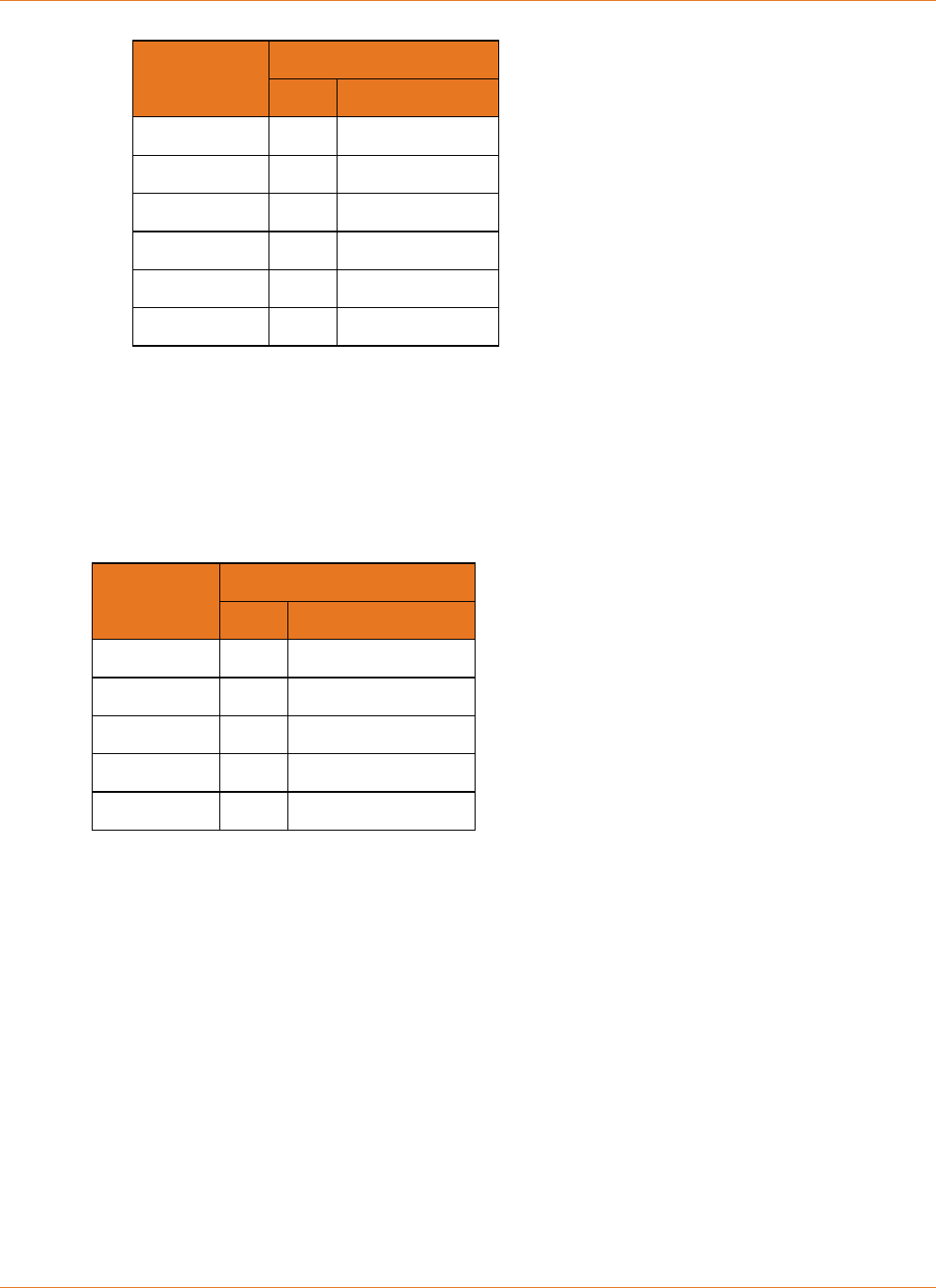
The following table shows rated and recommended storage temperatures for Touchstone Li-
Ion batteries.
Temperature
Min Max
Rated −20°C (−4°F) 60°C (140°F)
Recommended 10°C (50°F) 25°C (77°F)
Extended Storage
ARRIS recommends that you deploy batteries as soon as possible. If batteries are stored
before deployment, the following considerations apply.
Note: Storage at temperatures above 25°C (77°F) results in reduced battery life and is not
recommended.
If batteries have been in storage, recharge and test the batteries in an ARRIS device before
deploying. Recycle bad batteries.
The maximum recommended storage time for Li-Ion batteries is 16 months from date of
manufacture. Contact ARRIS Technical Support with the battery serial number to determine
the approximate date of manufacture.
Disposal
Some locales may require recycling of Li-Ion batteries. ARRIS recommends recycling all
batteries regardless of local ordinances.
In Europe, battery disposal is governed by Directive 2002/96/EC of the European Parliament
and of the Council on Waste Electrical and Electronic Equipment (WEEE). WEEE could

Chapter 2: Safety Considerations
STANDARD Revision 2.5 Touchstone Release 2.5 Reference Guide
© 2008-2016 ARRIS Enterprises LLC. All Rights Reserved. 10
potentially prove harmful to the environment; as such, batteries must not be disposed as
unsorted municipal waste, but rather collected separately and disposed of in accordance with
local WEEE ordinances.

STANDARD Revision 2.5 Touchstone Release 2.5 Reference Guide
© 2008-2016 ARRIS Enterprises LLC. All Rights Reserved. 11
Chapter 3
Core Functions
This chapter describes the core functionality of the Touchstone battery charging system.
Charger Initialization Times
When a Touchstone device is connected to AC power, whether for the first time or after
replacing a battery, it begins a battery test. The battery test has three phases:
1. Initial charging
2. Discharging
3. Recharging
The time required for this initial charge/test/recharge cycle depends on both the model and
installed battery type, as shown in the following tables.
Total Initialization Time (hours) per Battery Type and 10-pack Ordering Code
BPB022S BPB024S BPB026S BPB044S BPB044H BPB052H BPB066H BPB088S BPC088S BPD088H
Model 718003 721944 789699 718005 722841 801190 785170 721192 722842 785171
TM502G 72 85 85 144 144 170 - - - -
TM504G 72 85 85 144 144 170 - 288 - -
TM552G 72 85 85 144 144 170 - - - -
TM602G 72 85 85 144 144 170 - 288 - -
WTM652G 72 85 85 144 144 170 - 288 - -
TM604G 72 85 85 144 144 170 - 288 - -
TM608G - - - 144 144 170 - - 288 -
TM702G 72 85 85 144 78 92 - - - -
TM722G 72 85 85 144 78 92 120 - - 160
TM802G 72 85 85 144 78 92 120 - - 160
TM804G 72 85 85 144 78 92 120 - - 160
TM822G 72 85 85 144 78 92 120 - - 160
TG852G 72 85 85 144 78 92 - - - -
TG862G 72 85 85 144 78 92 - - - -
TG1602G 72 85 85 144 78 92 120 - - 160
TG1652G 72 85 85 144 78 92 - - - -
TG1662G 72 85 85 144 78 92 - - - -

Chapter 3: Core Functions
STANDARD Revision 2.5 Touchstone Release 2.5 Reference Guide
© 2008-2016 ARRIS Enterprises LLC. All Rights Reserved. 12
Total Initialization Time (hours) per Battery Type and 10-pack Ordering Code
BPB022S BPB024S BPB026S BPB044S BPB044H BPB052H BPB066H BPB088S BPC088S BPD088H
Model 718003 721944 789699 718005 722841 801190 785170 721192 722842 785171
TG1672G 72 85 85 144 78 92 - - - -
TG1682G 72 85 85 144 78 92 - - - -
MG2402G 72 85 85 144 78 92 - - - -
TG2472G 72 72 85 144 78 92 - - - -
TM3202G 72 85 85 144 78 92 120 - - 160
MG5125G - - - 144 78 92 - - 288 -
MG5225G - - - 144 78 92 - - 288 -
MG6225G - - - 144 78 92 - - - -
MG6325G - - - 144 78 92 - - - -
MG6425G - - - 144 78 92 - - - -
The battery test checks the battery safety, validity, and capacity, and calibrates the battery
gauge. Note that the battery gauge (described below) has degraded accuracy until the test
completes. While testing, the arrisMtaDevBatteryOperState object has a value of
testInProgress
(13).
Battery Gauge Calibration and Accuracy
Touchstone firmware uses several MIB objects to provide an estimate of battery power:
upsEstimatedMinutesRemaining
When the eMTA is running on AC power, this object provides estimated hold-up time if
the eMTA switches to battery power. When running on battery power, this object
provides the estimated hold-up time remaining.
upsEstimatedChargeRemaining
Provides an estimate of the current battery charge as a percentage of the full charge.
The eMTA calibrates the battery gauge under the following conditions:
Whenever a battery pack is installed.
Every 180 days (see "see "Scheduling Tests (page 37)" for details).
When commanded to perform a test (see "see "Scheduling Tests (page 37)" for details).
The calibration process measures the capacity of the battery pack (called the Battery Capacity
Test) and uses that data along with the Idle Power of the eMTA
(arrisMtaDevPwrSupplyTypicalIdlePwr) to populate the battery gauge MIB objects
mentioned above. The calibration process always assumes that the
arrisMtaDevPwrSupplyEnableDataShutdown object has not been modified from its default
setting (15 minutes). If data shutdown is modified or disabled, the battery gauge accuracy is
impacted.

Chapter 3: Core Functions
STANDARD Revision 2.5 Touchstone Release 2.5 Reference Guide
© 2008-2016 ARRIS Enterprises LLC. All Rights Reserved. 13
During the Battery Capacity Test, the arrisMtaDevBatteryOperState and
arrisMtaDevBatteryOperSubState MIB objects normally progress through the following states
in the following order:
arrisMtaDevBatteryOperState arrisMtaDevBatteryOperSubState
normal
(12) Test in Progress, Battery is Charging
normal
(12) Test in Progress, Battery Test Load ON
normal
(12) Test in Progress, Battery Test Load ON & Bat
Low
normal
(12) Test in Progress, Battery is Charging & Bat
Low
normal
(12) Test in Progress, Battery is Charging
normal
(12) Test in Progress
normal
(12) Battery Backup Normal
When the calibration process completes, the battery gauge accuracy is about ±5%. If the
battery capacity test has been delayed for a long period of time, or if the
arrisMtaDevPwrSupplyEnableDataShutdown object is adjusted, the accuracy degrades. If the
battery capacity test has not been performed at all on the installed battery (which can be
done by setting the arrisMtaDevPwrSupplyFullChargeTime object to a value between
1
and
16
when the eMTA is first powered up), the Fuel Gauge accuracy could be extremely poor
depending on the condition of the installed battery.
Scheduling and Maintenance
To assess whether the battery needs to be replaced, the Telephony Modem periodically
performs a battery test. During the battery test, the Telephony Modem charges, discharges,
and recharges the battery pack.
The Telephony Modem re-tests the battery every 180 days afterwards (default value).
However, the scheduling of this test may be paused or accelerated through provisioning. See
the Touchstone Firmware Guide for your current release for more information.
Booting from Battery (Model 6 and newer)
Model 6 and newer Telephony Modems support a "Boot from Battery" feature that allows the
Telephony Modem to begin service without AC power.
To start a Telephony Modem from its battery, insert the battery (if necessary) and press and
hold the Reset button on the back of the Telephony Modem for at least 1 second. The battery
gauge will not be accurate until AC voltage is applied and the Telephony Modem has
performed the battery calibration test.

Chapter 3: Core Functions
STANDARD Revision 2.5 Touchstone Release 2.5 Reference Guide
© 2008-2016 ARRIS Enterprises LLC. All Rights Reserved. 14
Specifications
The following are general specifications for batteries and the charging system.
Physical:
Operating Temperature °F (°C) 32 to 122
(0 to 50)
Operating Relative Humidity (Min.-Max.) 5-95% (non-condensing)
Storage Temperature °F (°C) -4 to 140
(-20 to 60)
Storage above 77°F (25°C) reduces battery life and is not recommended.
Operating and Storage Altitude ft (m) -200 to 12,000
(-61 to 3,658)
Battery Shelf Life
(without recharge, 25°C) 16 months
Battery Life Expectancy
(with 2 discharge cycles per year, 25°C) 6 to 10 years
Color
BPB022S Black
BPB024S Light Grey
BPB026S Green
BPB044S Black
BPB044H Light Grey
BPB052H Green
BPD066H Black
BPB088S Black
BPC088S Black
BPD088H Black
Dimensions
(H x W x D)
BPB022S,
BPB024S,
BPB026S
1.2 x 3.1 x 1.8 in.
(3.1 x 7.9 x 4.7 cm)
BPB044S,
BPB044H,
BPB052H
1.2 x 5.7 x 1.8 in.
(3.1 x 14.5 x 4.7 cm)
BPD066H 6.3 x 2.0 x 2.1 in.
(16.0 x 5.1 x 5.3 cm)
BPB088S 2.0 x 6.9 x 2.0 in.
(5.1 x 17.6 x 5.1 cm)
BPC088S 2.0 x 2.0 x 6.9 in.
(5.0 x 4.7 x 14.4 cm)
BPD088H 6.3 x 2.0 x 2.1 in.
(16.0 x 5.1 x 5.3 cm)
Weight:
BPB022S ~4.1 oz (111–117 g)
BPB024S ~4.1 oz (111–117 g)

Chapter 3: Core Functions
STANDARD Revision 2.5 Touchstone Release 2.5 Reference Guide
© 2008-2016 ARRIS Enterprises LLC. All Rights Reserved. 15
BPB026S ~4.1 oz (111–117 g)
BPB044S ~7.8 oz (214–222 g)
BPB044H ~7.8 oz (214–222 g)
BPB052H ~7.8 oz (214–222 g)
BPD066H ~12.8 oz (360–365 g)
BPB088S ~16.0 oz (455–457 g)
BPC088S ~14.5 oz (410–411 g)
BPD088H ~16.0 oz (455–457 g)
Interface Connector Type: 5-Pin, 2.0 mm
Electrical:
Output Voltage Range +6.0 to +8.4 V DC
Output Power (Max. continuous) 16.8 W at 45°C
Cell Type Lithium-Ion 18650
Number of Cells
BPB022S 2
BPB024S 2
BPB026S 2
BPB044S 4
BPB044H 4
BPB052H 4
BPD066H 6
BPB088S 8
BPC088S 8
BPD088H 8
Pack Capacity
BPB022S 2200 mAh
BPB024S
(older) 2400 mAh
BPB024S 2600 mAh
BPB026S 2600 mAh
BPB044S 4400 mAh
BPB044H 4400 mAh
BPB052H 5200 mAh
BPD066H 6600 mAh
BPB088S 8800 mAh
BPC088S 8800 mAh
Charge Current (Max.)
BPB022S 115 mA
BPB024S 115 mA

Chapter 3: Core Functions
STANDARD Revision 2.5 Touchstone Release 2.5 Reference Guide
© 2008-2016 ARRIS Enterprises LLC. All Rights Reserved. 16
BPB026S 115 mA
BPB044S 115 mA
BPB044H 500 mA
BPB052H 500 mA
BPD066H 500 mA
BPB088S 115 mA
BPC088S 115 mA
BPD088H 500 mA
Standards:
Hazardous Materials Regulations and Procedures CFR Title 49, Section 173, Subsection 185
EN 300386
FCC Part 15, Subpart B
UL 60950
EN 60950
IEC 60950
SA AS/NZS 60950
RoHS Compliant 2002/95/EC
Replacing a Battery
Use this procedure to replace or install a battery.
• Installing or Replacing a 2-cell Battery .............................................. 16
• Installing or Replacing a 4-cell Battery .............................................. 18
• Installing or Replacing a 6-cell or 8-cell Battery (2- and 4-
line modems) ..................................................................................... 19
•
Installing or Replacing a 8-cell Battery (TM608) ............................... 21
Installing or Replacing a 2-cell Battery
Follow these steps to replace a 2-cell battery in a supported Telephony Modem.
Chapter 3: Core Functions
STANDARD Revision 2.5 Touchstone Release 2.5 Reference Guide
© 2008-2016 ARRIS Enterprises LLC. All Rights Reserved. 17
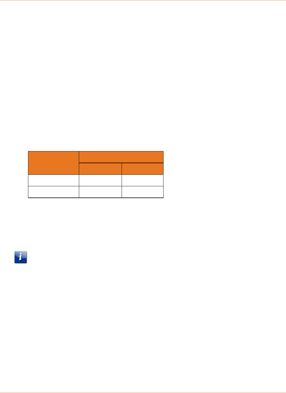
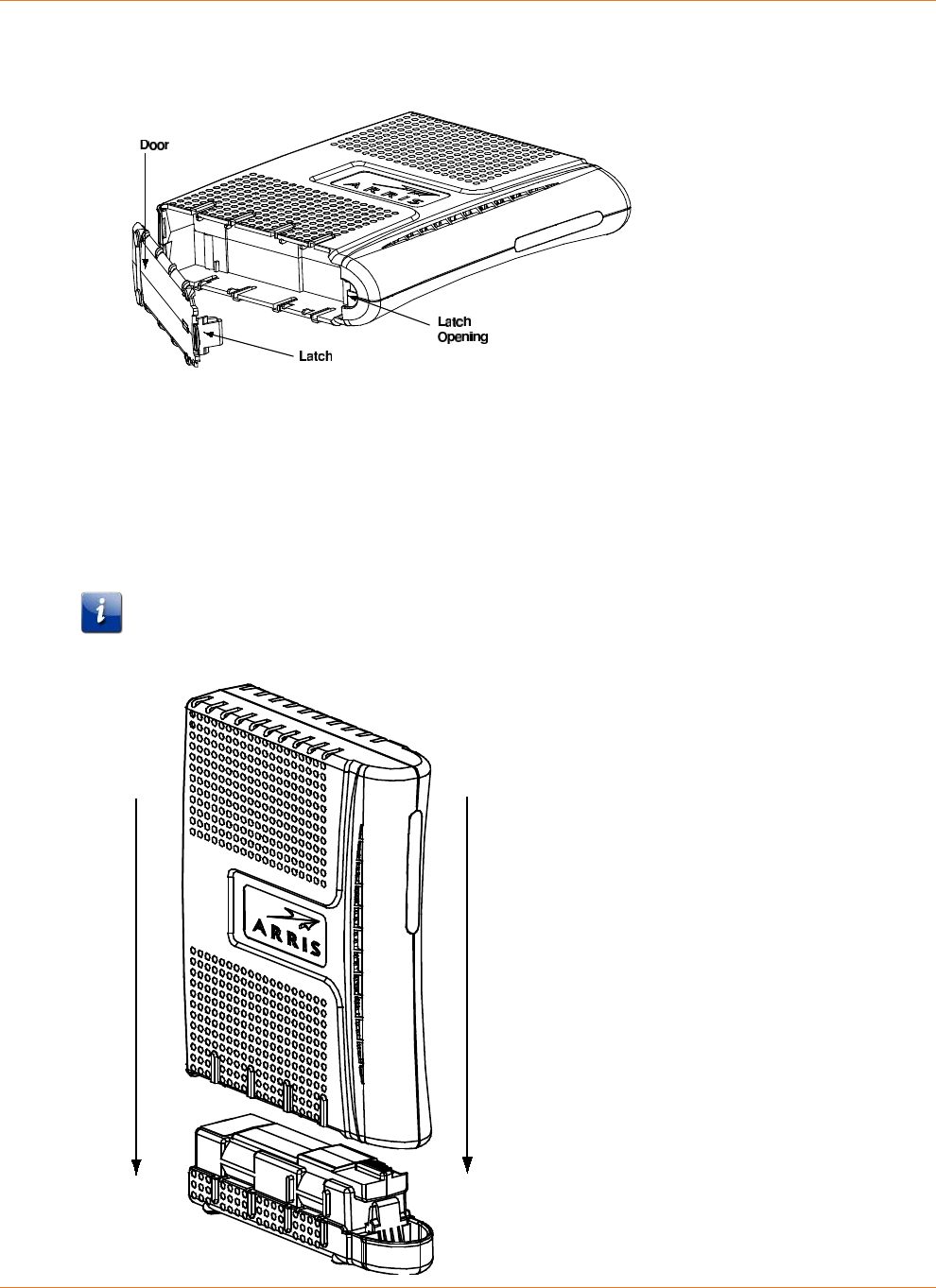
1. Insert a finger into the latch opening, press down and pull back on the latch holding the
battery door (on the bottom of the Telephony Modem). Pull the door toward you. Set the
door aside in a safe place.
2. If you are installing a new battery, skip to step 4.
3. To remove the battery from the Telephony Modem, position your finger in the battery
opening area and use leverage to dislodge the battery while pulling it straight back.
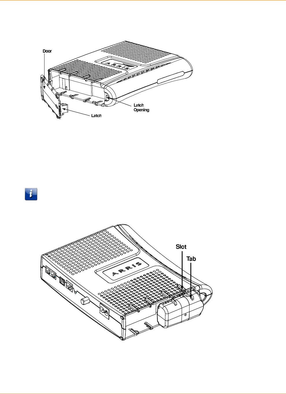
4. Hold the battery pack so that the guides on the battery align with the slots on the
Telephony Modem and slide the battery into the bay. The diagram below shows the
proper orientation.
Note: Batteries will not insert completely into the Telephony Modem if not oriented
correctly. The battery should slide into the bay without significant force. Line up the slots
in the battery bay with the guides on the battery.
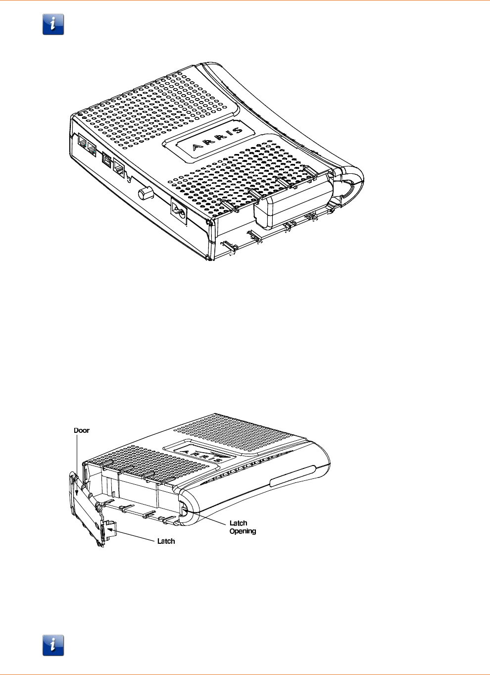
5. Push the battery pack into the bay until it seats into place. The following diagram shows a
Telephony Modem with a 2-cell battery pack installed.
Chapter 3: Core Functions
STANDARD Revision 2.5 Touchstone Release 2.5 Reference Guide
© 2008-2016 ARRIS Enterprises LLC. All Rights Reserved. 18
Note: The Telephony Modem will not begin operating until you apply AC power or press
the Reset button.
6. Replace the door. To do so, place the hinge tabs of the battery door into the receiver slots
inside the Telephony Modem battery compartment on the opposite end of the battery
opening slot. Rotate the door toward the unit until the latch snaps back into place.
Installing or Replacing a 4-cell Battery
Follow these steps to replace a 4-cell battery in a supported Telephony Modem.
1. Insert a finger into the latch opening, press down and pull back on the latch holding the
battery door (on the bottom of the Telephony Modem). Pull the door toward you. Set the
door aside in a safe place.
2. If you are installing a new battery, skip to step 4.
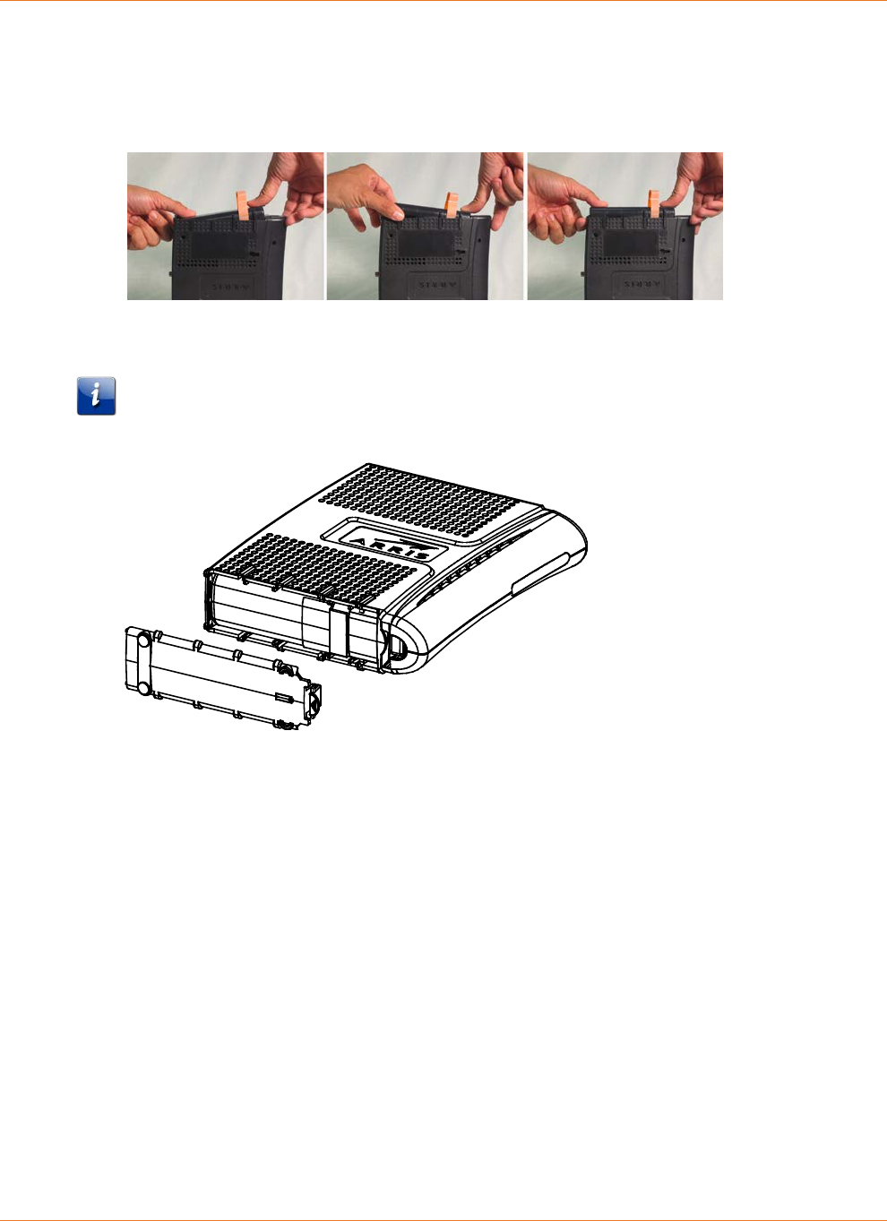
3. To remove a 4-cell battery, use the pull strap to pull the battery out of the bay.
4. Hold the battery pack so that the guides on the battery align with the slots on the
Telephony Modem and slide the battery into the bay. The diagram below shows the
proper orientation.
Note: Batteries will not insert completely into the Telephony Modem if not oriented
correctly. The battery should slide into the bay without significant force. Line up the slots
Chapter 3: Core Functions
STANDARD Revision 2.5 Touchstone Release 2.5 Reference Guide
© 2008-2016 ARRIS Enterprises LLC. All Rights Reserved. 19
in the battery bay with the guides on the battery and apply even pressure on both ends of
the battery.
WRONG
WRONG
RIGHT
1. Push the battery pack into the bay until it seats into place. The following diagram shows a
Telephony Modem with a 4-cell battery pack installed.
Note: The Telephony Modem will not begin operating until you apply AC power or press
the Reset button.
2. Replace the door. To do so, place the hinge tabs of the battery door into the receiver slots
inside the Telephony Modem battery compartment on the opposite end of the battery
opening slot. Rotate the door toward the unit until the latch snaps back into place.
Installing or Replacing a 6-cell or 8-cell Battery (2- and 4-line
modems)
Follow these steps to replace a 6-cell or 8-cell battery in a supported 2- or 4-line Telephony
Modem. Note that not all Telephony Modems support the 8-cell battery. Only TM722 and
Model 8 (TM802, TM804, TM822) Telephony Modems support the 6-cell battery.
Chapter 3: Core Functions
STANDARD Revision 2.5 Touchstone Release 2.5 Reference Guide
© 2008-2016 ARRIS Enterprises LLC. All Rights Reserved. 20
1. Remove the battery door. Insert a finger into the latch opening, press down and pull back
on the latch holding the battery door (on the bottom of the Telephony Modem). Pull the
door toward you. Set the door aside in a safe place.
2. If you are installing a new battery, skip to step 4.
3. To remove a 6-cell or 8-cell battery, grasp the battery, pull back on the latch, and gently
rock the battery out of the bay.
4. Place the new (or replacement) 6-cell or 8-cell battery on a firm horizontal surface.
5. Position the Telephony Modem over the battery, making sure to line up the slots on the
battery bay with the tabs on the battery. Push straight down on the Telephony Modem
until the battery latch clicks into place.
Note: You may need to push down gently on the front of the Telephony Modem to latch
the battery into place.
Chapter 3: Core Functions
STANDARD Revision 2.5 Touchstone Release 2.5 Reference Guide
© 2008-2016 ARRIS Enterprises LLC. All Rights Reserved. 21
6. If the Telephony Modem is wall-mounted, replace it on the mounting screws.
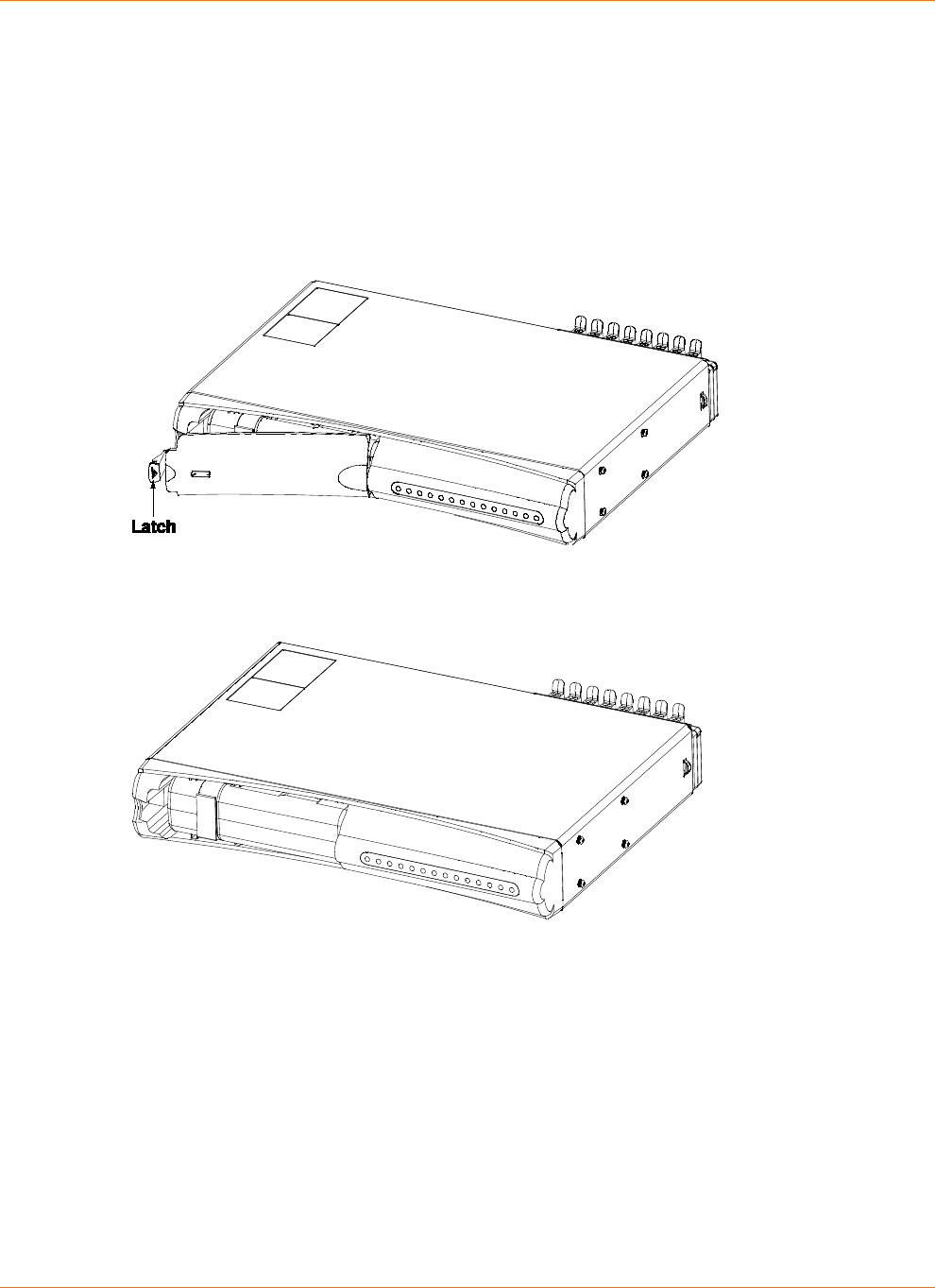
Installing or Replacing a 8-cell Battery (TM608)
Follow these steps to replace an 8-cell battery in a TM608. The TM608 has a battery bay in the
front panel.
1. Pull the battery door latch toward the center of the Telephony Modem and remove the
battery door. Set the battery door aside.
2. If necessary, remove the existing battery. Some batteries have a pull strap as shown in the
example below.
3. Insert the backup battery as shown below.
4. Replace the battery door:
1. Insert the battery door tab into the slot in the right side of the battery bay.
2. Swing the battery door closed and press gently until it latches.

STANDARD Revision 2.5 Touchstone Release 2.5 Reference Guide
© 2008-2016 ARRIS Enterprises LLC. All Rights Reserved. 22
Chapter 4
System Performance
The Telephony Modem charging system is designed to maximize battery life and optimize
hold-up times. This chapter describes important features about the charging system.
Typical Lifetimes
Li-Ion batteries used in Touchstone products typically have a lifetime of 6 to 10 years when
deployed immediately.
The following factors may impact battery lifetime:
High temperatures:
Extended exposure to temperatures above 25°C (77°F) reduces battery life. Warehouses
(pre-deployment) and garage or attic installations can exceed this temperature, especially
during summer months.
Frequent discharging:
Telephony Modems powered by switched outlets, or installed in areas with unreliable
utility power, may experience reduced battery life. Whenever possible, use an unswitched
outlet to power the Telephony Modem.
Note: The Telephony Modem partially discharges the battery during periodic capacity
testing. Estimated battery lifetimes include this testing. By default, the Telephony Modem
performs capacity testing every 180 days; you can change the interval by changing a MIB
object in an SNMP browser or the configuration file. See "see "Scheduling Tests (page 37)"
for more information.
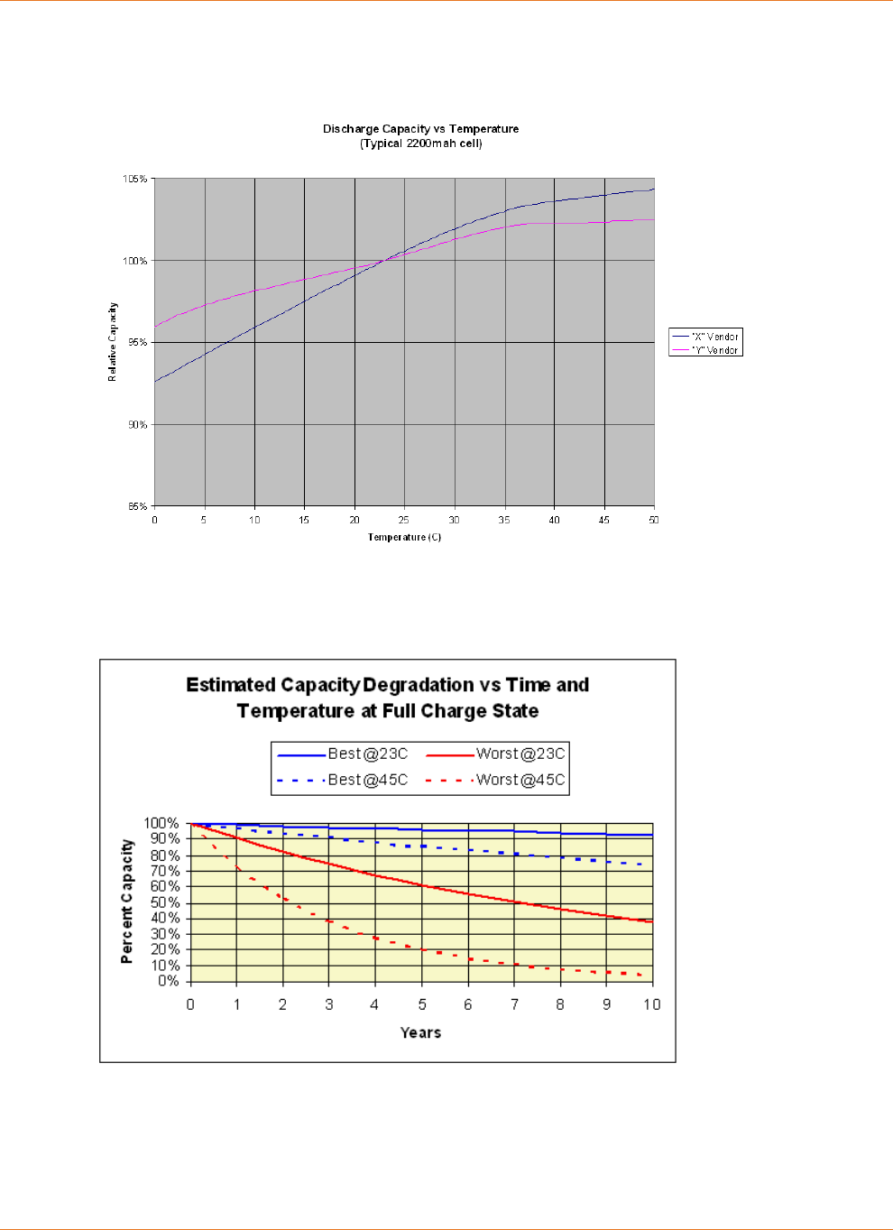
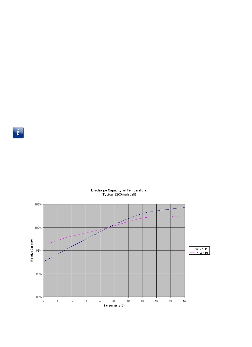
Temperature vs. Battery Capacity
Touchstone battery capacity figures assume:
a storage temperature of 25 °C
two discharge cycles per year
Chapter 4: System Performance
STANDARD Revision 2.5 Touchstone Release 2.5 Reference Guide
© 2008-2016 ARRIS Enterprises LLC. All Rights Reserved. 23
In general, hold-up times decrease with lower battery temperature, and increase slightly at
higher temperatures (up to 40 °C) as shown in the following chart:
Batteries lose capacity over time, losing capacity faster at higher temperatures or when
discharged more often. The following graph shows capacity loss per year at various
temperatures.
Power Failure Operation
When a Telephony Modem with battery backup capabilities loses AC power, it immediately
takes the following actions:
Chapter 4: System Performance
STANDARD Revision 2.5 Touchstone Release 2.5 Reference Guide
© 2008-2016 ARRIS Enterprises LLC. All Rights Reserved. 24
1. Shuts off some LEDs to conserve battery power. The Power LED flashes and the Telephone
and DOCSIS LEDs continue to operate normally.
2. Disables the ability to download new firmware until the AC power is restored.
Downloading firmware would cause a reset (and terminate service) upon completion of
the download.
In addition, the Telephony Modem by default shuts down the data services running over wifi,
and the Ethernet and USB ports, after a set amount of time. You can change the amount of
time before the Telephony Modem disables data services, or disable data shutdown
altogether. See the Touchstone Firmware Guide for details.
Note: Disabling data shutdown reduces battery hold-up time. The reduction depends on the
model type (DTM602 and Gateway products, for example, have a much higher reduction than
a TM602 or TM702).
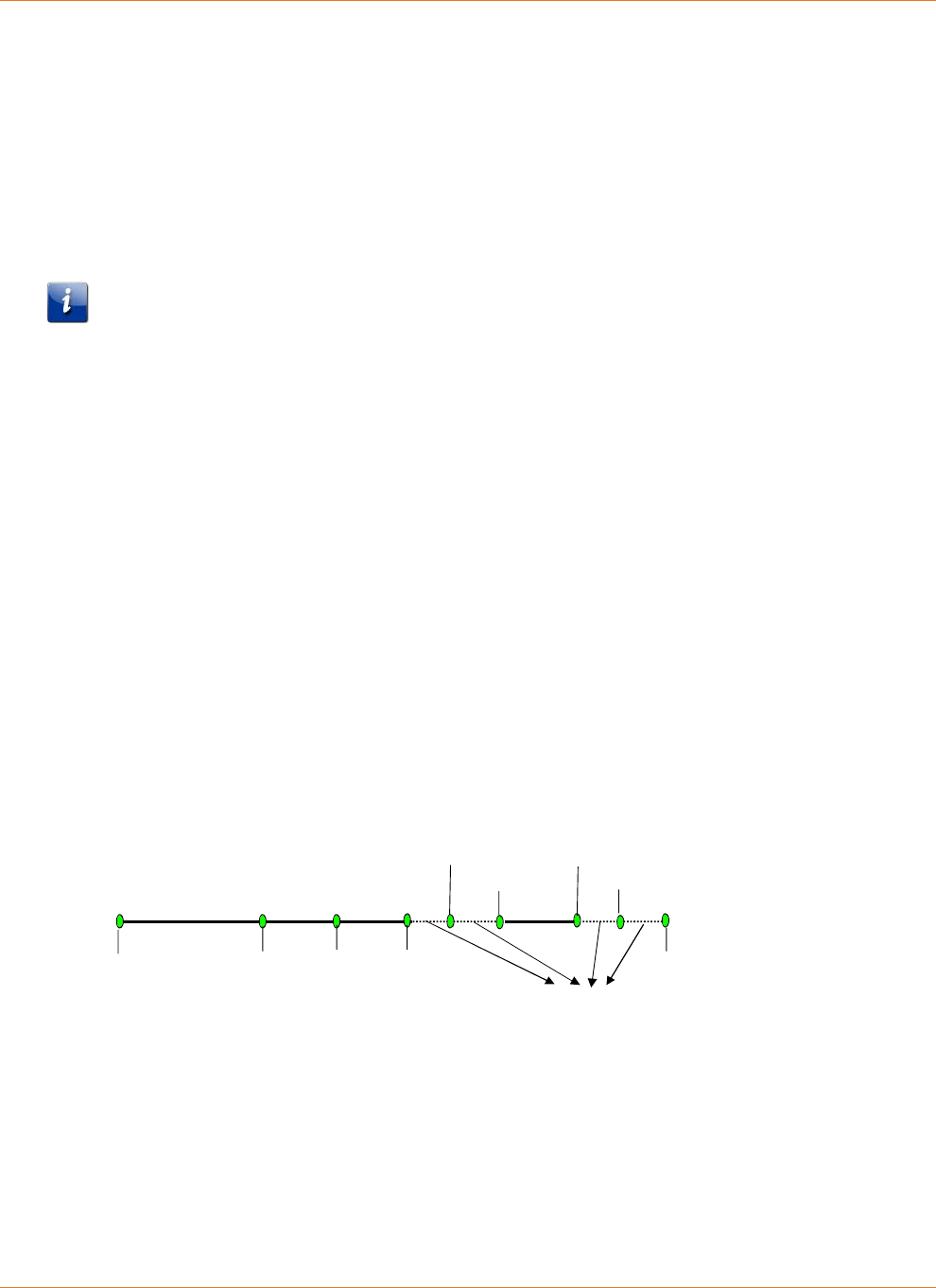
Power Outage Recovery and Timing
Telephony Modems with battery backup automatically switch to DC power upon loss of the
AC power supply. There is no interruption to the modem operation as a result of the switch to
battery power. Note that there are certain changes to modem functions while operating on
battery power, as described above.
Telephony Modems without battery backup, including units deployed without batteries, and
battery-backed units which experience loss of AC power durations which exceed installed
battery capacity, cease to operate upon loss of AC power. Recovery timing from power loss
events depends largely on the recovery capability of network components. However, there is
a small eMTA contribution to the amount of time required to fully recover. For DOCSIS 2.0
ARRIS Touchstone products, this time is approximately 25 to 30 seconds. DOCSIS 3.0 product
recovery time is often longer, as they range on several upstreams and downstreams.
The following figure shows a representation of this recovery timing.
varies 5 seconds 5 seconds <5 seconds
Power
restored
Boot Up
Sequence
Complete
Locked to
cached
Downstream
Frequency
Ranged on
cached
Upstream
with cached
power level
Frequency
Time dependent on network response
DT Restored
CM
DHCP
Discover
CM TFTP
Download
EMTA
DHCP
Discover
EMTA TFTP
Download
Typical Hold-up Times
Use the following information to estimate battery hold-up times for different Telephony
Modem models. Note that any hold-up time predictions are necessarily estimates, given the
number of variables involved.
Chapter 4: System Performance
STANDARD Revision 2.5 Touchstone Release 2.5 Reference Guide
© 2008-2016 ARRIS Enterprises LLC. All Rights Reserved. 25
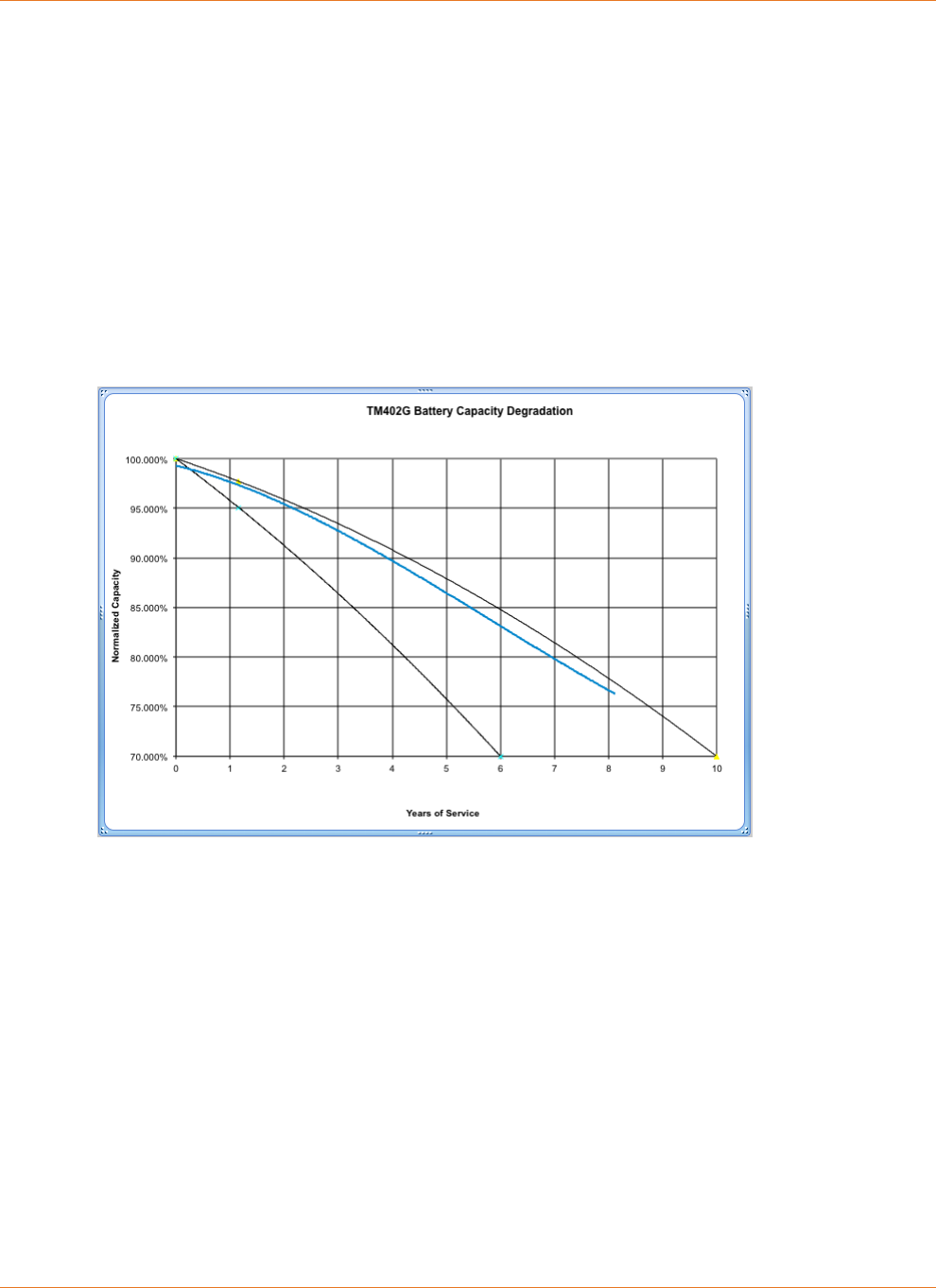
Factors Affecting Hold-up Times
The following factors can affect hold-up times:
Capacity vs. Age
The following graph shows typical battery degradation with age. The area between the black
curved lines shows the predicted capacity range over time; for example, after four years, a
typical Li-Ion battery should have roughly 82% to 91% of its rated capacity.
The blue line shows actual test results averaged over 8 years of testing. Note that advances in
battery technology and manufacturing, since this long-term test began, have improved both
capacity and reliability for current batteries.
Touchstone Model 5 and newer eMTAs generate a "Battery Replace" log when the battery has
degraded to the point where it can provide 1 hour (2- or 4-cell batteries) or 2 hours (8-cell
batteries) of holdup time. The actual holdup time threshold can be changed by setting the
arrisMtaDevPwrSupplyReplaceBatTime object to the desired charge level.
Boost Current Mode
High ("boost") loop current may be required for proper operation with certain CPE devices.
Loop current settings are:
20mA (standard): all models
34mA (boost): all models
40mA (boost): Model 6/7/8 using NorthAmerica-High template
Some firmware loads set boost current as the default; see the Touchstone Firmware Guide for
the firmware version deployed in your network for details.
Boost current mode can affect hold-up times depending on the number of lines in use.
Chapter 4: System Performance
STANDARD Revision 2.5 Touchstone Release 2.5 Reference Guide
© 2008-2016 ARRIS Enterprises LLC. All Rights Reserved. 26
no lines in use: negligible impact
1 line in use: approx. 5% reduction in hold-up time
2 lines in use: approx. 10% reduction in hold-up time
Data Shutdown
By default, Touchstone firmware shuts down all data interfaces (Ethernet, USB, wireless) after
power remains off for a set time (the default depends on the model). Set the
arrisMtaDevPwrSupplyEnableDataShutdown MIB object to
disabled
(2) to disable data
shutdown. Some subscribers may prefer to have data services available at the expense of
reduced hold-up times.
Disabling data shutdown entirely results in a 10% to 20% reduction in hold-up time, depending
on:
network activity
Telephony Modem model
number of lines off-hook
Note: For the WTM552 and WTM652, and all Data Gateway and Telephony Gateway
products, disabling data shutdown reduces hold-up times by 30% to 50%.
Battery Pack Temperature
Hold-up times increase slightly above 25°C (while reducing battery lifetime). Temperatures
below 15°C reduce hold-up times.
Other Factors
Other factors that can affect hold-up time include:

Chapter 4: System Performance
STANDARD Revision 2.5 Touchstone Release 2.5 Reference Guide
© 2008-2016 ARRIS Enterprises LLC. All Rights Reserved. 27
Number of battery charge/discharge cycles — the default configuration completely
discharges the battery every six months for testing and calibration purposes. Frequent
extended power outages, or subscribers removing power (using a power strip or switched
outlet), can cause premature battery deterioration.
eMTA configuration — in addition to boost current and data shutdown changes described
above, Touchstone firmware allows a number of changes to the charging system. See the
"Provisioning" chapter for details.
Lines off-hook — lines in use require more power than at idle, even without a connection
(for example, receivers jarred off-hook during an earthquake).
Estimated Hold-up Times by Model
The following tables provide estimated hold-up times for each Telephony Modem model,
assuming:
new batteries
room temperature
data shutdown enabled
boost current disabled
Note: The "Lines off-hook" measurements assume the lines remain off-hook constantly while
running on battery power. Thus, the tables provide an estimated range of hold-up times based
on subscriber telephone usage during the power outage.
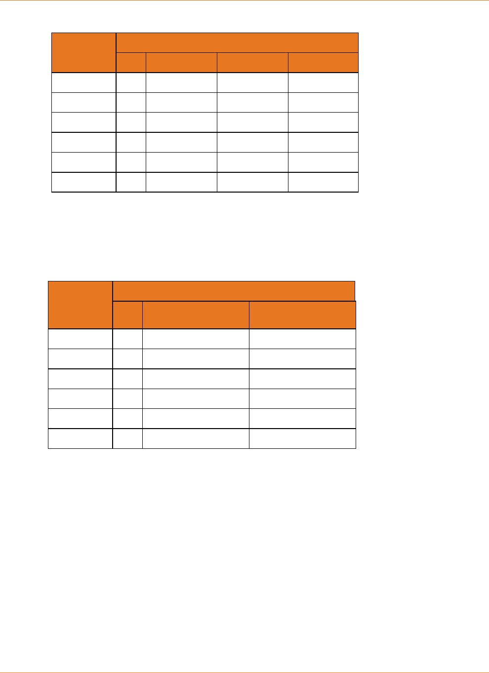
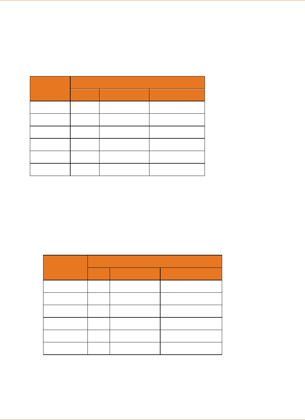
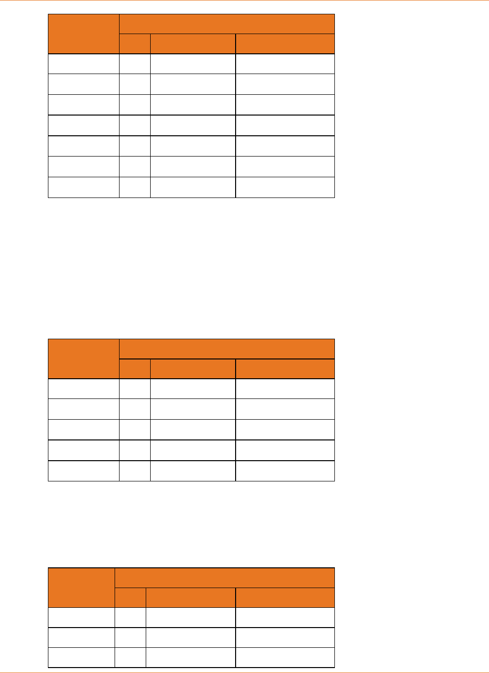
TM502
The following table shows typical hold-up times for the TM502 Telephony Modem, with:
data shutdown after 15 minutes
23 mA loop current
Battery
Model
Hold-up Time (hours)
Idle 1 Line Off-hook
BPB022S 5 3
BPB024S 5 3
BPB026S 5 3
BPB044S/H 10 6
BPB052H 10 6
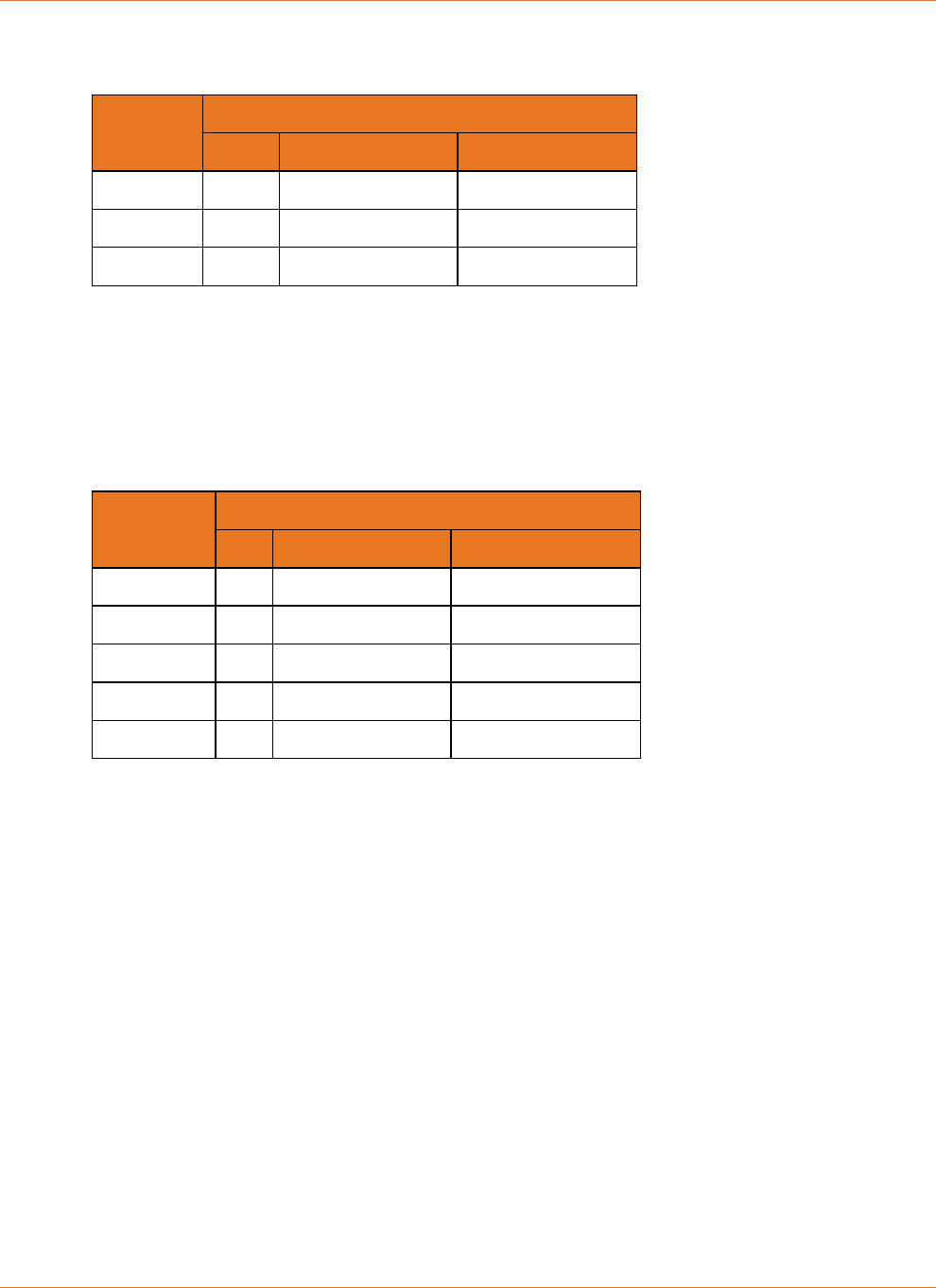
TM504
The following table shows typical hold-up times for the TM504 Telephony Modem, with:
data shutdown after 15 minutes
23 mA loop current
Chapter 4: System Performance
STANDARD Revision 2.5 Touchstone Release 2.5 Reference Guide
© 2008-2016 ARRIS Enterprises LLC. All Rights Reserved. 28
Battery
Model
Hold-up Times (hours)
Idle 1 Line Off-hook
BPB022S 4 3
BPB024S 4 3
BPB026S 4 3
BPB044S/H 8 6
BPB052H 8 6
BPB088S/H 16 12
WTM552
The following table shows typical hold-up times for the WTM552 Telephony Modem, with:
data shutdown after 5 minutes
23 mA loop current
Battery
Model
Hold-up Times (hours)
Idle 1 Line Off-hook
BPB022S 5 3
BPB024S 5 3
BPB026S 5 3
BPB044S/H 10 6
BPB052H 10 6
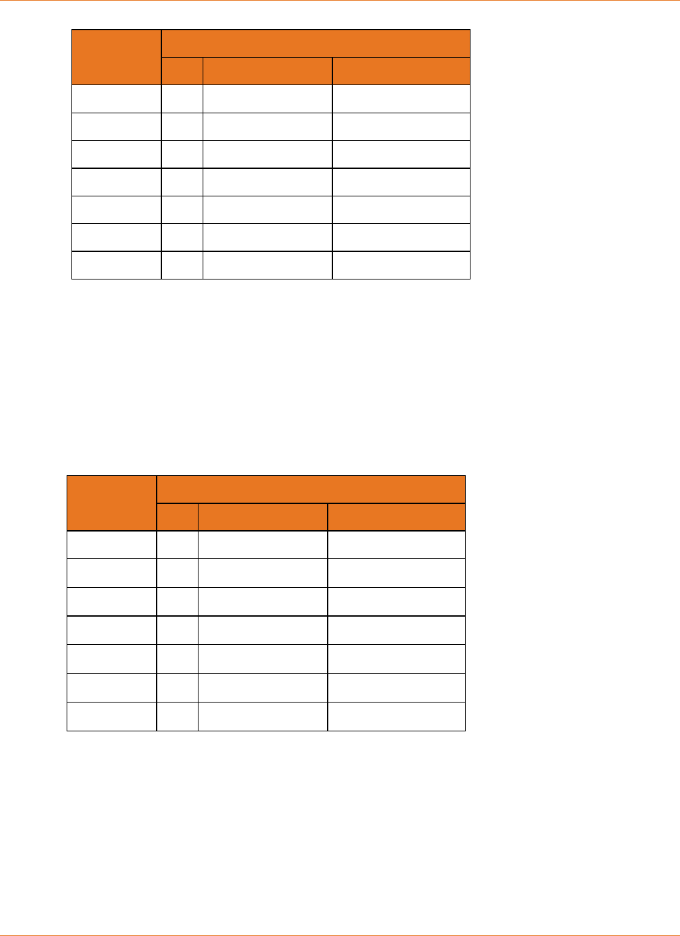
TM602
The following table shows typical hold-up times for the original TM602 Telephony Modem,
with:
data shutdown after 15 minutes
one line off-hook
various loop current settings
Chapter 4: System Performance
STANDARD Revision 2.5 Touchstone Release 2.5 Reference Guide
© 2008-2016 ARRIS Enterprises LLC. All Rights Reserved. 29
Battery
Model
Hold-up Times (hours) (1 Line Off-hook)
Idle 23 mA Loop 33 mA Loop 40mA Loop
BPB022S 6 3.5 3.33 3
BPB024S 8 5 4.5 4
BPB026S 8 5 4.5 4
BPB044S/H 12 7.66 6.66 6
BPB052H 12 7.66 6.66 6
BPB088S/H 24 15.33 13.33 12
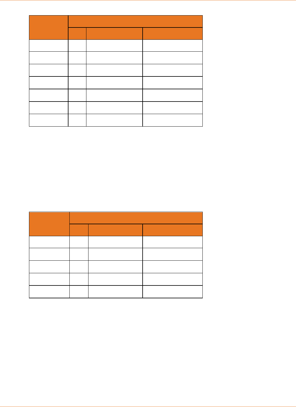
The following table shows typical hold-up times for the Phase 2 TM602 Telephony Modem,
with:
data shutdown after 15 minutes
one line off-hook
various loop current settings
Battery
Model
Hold-up Times (hours) (1 Line Off-hook)
Idle 23 mA Loop 40mA Loop
BPB022S 8 5 4
BPB024S 8 5 4
BPB026S 8 5 4
BPB044S/H 12 7.66 6
BPB052H 12 7.66 6
BPB088S/H 24 15.33 12
Chapter 4: System Performance
STANDARD Revision 2.5 Touchstone Release 2.5 Reference Guide
© 2008-2016 ARRIS Enterprises LLC. All Rights Reserved. 30
TM604
The following table shows typical hold-up times for the TM604 Telephony Modem, with:
data shutdown after 15 minutes
no lines or all four lines off-hook
various loop current settings
Battery
Model
Hold-up Times (hours) (4 Lines Off-hook)
Idle 23 mA Loop 40 mA Loop
BPB022S 6 2.5 1.5
BPB024S 7 3 2
BPB026S 7 3 2
BPB044S/H 12 5 3
BPB052H 12 5 3
BPB088S/H 24 10 6
WTM652, TG662
The following table shows typical hold-up times for the WTM652 Telephony Modem, with:
data shutdown after 5 minutes
no lines or one line off-hook
various loop current settings
Battery
Model
Hold-up Times (hours) (1 Line Off-hook)
Idle 23 mA Loop 40 mA Loop
BPB022S 6 3.5 3
BPB024S 8 5 4
BPB026S 8 5 4
BPB044S/H 12 7.66 6
BPB052H 12 7.66 6
BPB088S/H 24 15.33 12
TM608
The following table shows typical hold-up times for the TM608 Telephony Modem, with:
data shutdown after 15 minutes
no lines or all eight lines off-hook
Chapter 4: System Performance
STANDARD Revision 2.5 Touchstone Release 2.5 Reference Guide
© 2008-2016 ARRIS Enterprises LLC. All Rights Reserved. 31
various loop current settings
Battery
Model
Hold-up Times (hours) (8 Lines Off-hook)
Idle 23 mA Loop 40 mA Loop
BPB044S 8 2.75 1.5
BPB044H 8 2.75 1.5
BPC088S 16 5.5 3
TM702
The following table shows estimated hold-up times for the TM702 Telephony Modem, with:
data shutdown after 15 minutes
no lines or one line off-hook
various loop current settings
Battery
Model
Hold-up Times (hours) (1 Line Off-Hook)
Idle 23 mA Loop 40 mA Loop
BPB022S 4 3.25 2.75
BPB024S 4 3.5 3
BPB026S 4 3.5 3
BPB044S/H 8 6.5 5.5
BPB052H 8 6.5 5.5
TM722
The following table shows typical hold-up times for the TM722 Telephony Modem, with:
data shutdown after 15 minutes
no lines or one line off-hook
various loop current settings
Chapter 4: System Performance
STANDARD Revision 2.5 Touchstone Release 2.5 Reference Guide
© 2008-2016 ARRIS Enterprises LLC. All Rights Reserved. 32
Battery
Model
Hold-up Times (hours) (1 Line Off-hook)
Idle 23 mA Loop 40 mA Loop
BPB022S 4 3.25 2.75
BPB024S 4 3.5 3
BPB026S 4 3.5 3
BPB044S/H 8 6.5 5.5
BPB052H 8 6.5 5.5
BPD066H 12 9.5 8
BPD088H 16 13 11
TM802, TM822
The following table shows typical hold-up times for the TM802 and TM822 Telephony
Modems, with:
data shutdown after 15 minutes
no lines or one line off-hook
various loop current settings
Battery
Model
Hold-up Times (hours) (1 Line Off-Hook)
Idle 23 mA Loop 40 mA Loop
BPB022S 6 4 3.5
BPB024S 6 4 3.5
BPB026S 8 6 5
BPB044S/H 12 8 7
BPB052H 12 8 7
BPD066H 18 12 10.5
BPD088H 24 16 14
TM804
The following table shows typical hold-up times for the TM804 Telephony Modem, with:
data shutdown after 15 minutes
no lines or one line off-hook
various loop current settings
Chapter 4: System Performance
STANDARD Revision 2.5 Touchstone Release 2.5 Reference Guide
© 2008-2016 ARRIS Enterprises LLC. All Rights Reserved. 33
Battery
Model
Hold-up Times (hours) (1 Line Off-Hook)
Idle 23 mA Loop 40 mA Loop
BPB022S 6 4 3.5
BPB024S 6 4 3.5
BPB026S 6 4 3.5
BPB044S/H 12 8 7
BPB052H 12 8 7
BPD066H 18 12 10.5
BPD088H 24 16 14
TG852, TG862
The following table shows typical hold-up times for the TG852 and TG862 Telephony
Gateways, with:
data shutdown after 5 minutes
no lines or one line off-hook
various loop current settings
Battery
Model
Hold-up Times (hours) (1 Line Off-hook)
Idle 23 mA Loop 40 mA Loop
BPB022S 6 4 3.5
BPB024S 6 4 3.5
BPB026S 8 6 5
BPB044S/H 12 8 7
BPB052H 12 8 7
TM1602, TG1652, TG1662, TG1672, TG1682, TM3202
The following table shows typical hold-up times for the TM1602 and TM3202 Telephony
Modems, and the TG1652, TG1662 TG1672, and TG1682 Telephony Gateways, with:
data shutdown after 5 minutes
one line off-hook
various loop current settings
Chapter 4: System Performance
STANDARD Revision 2.5 Touchstone Release 2.5 Reference Guide
© 2008-2016 ARRIS Enterprises LLC. All Rights Reserved. 34
Battery
Model
Hold-up Times (hours) (1 Line Off-hook)
Idle 23 mA Loop 40 mA Loop
BPB022S 4 3 2.5
BPB024S 4 3 2.5
BPB026S 4 3 2.5
BPB044S/H 8 6 5
BPB052H 8 6 5
BPB066H* 12 9 7.5
BPB088H* 16 12 10
*TM1602/TM3202 only
TG1682, TG2472, MG2402
The following table shows typical hold-up times for the TG1682 Telephony Gateway and
MG2402 Media Gateway, with:
immediate data shutdown
no lines or one line off-hook
various loop current settings
Battery
Model
Hold-up Times (hours) (1 Line Off-hook)
Idle 23 mA Loop 40 mA Loop
BPB022S 4 3 2.5
BPB024S 4 3 2.5
BPB026S 4 3 2.5
BPB044S/H 8 6 5
BPB052H 8 6 5
MG5125, MG5225
The following table shows typical hold-up times for the MG5125 and MG5225 Media
Gateways.
Battery
Model
Hold-up Times (hours)
Idle 1 Line Off-hook 2 Lines Off-hook
BPB044S/H 8 6 5
BPB052H 8 6 5
BPC088S 16 12 10

Chapter 4: System Performance
STANDARD Revision 2.5 Touchstone Release 2.5 Reference Guide
© 2008-2016 ARRIS Enterprises LLC. All Rights Reserved. 35
MG6125, MG6225, MG6325, MG6425
The following table shows typical hold-up times for the MG6125, MG6225, MG6325, and
MG6425 Media Gateways, with:
immediate data shutdown
no lines or one line off-hook
various loop current settings
Battery
Model
Hold-up Times (hours) (1 Line Off-hook)
Idle 23 mA Loop 40 mA Loop
BPB022S 4 3 2.5
BPB024S 4 3 2.5
BPB026S 5 4 3.5
BPB044S/H 8 6 5
BPB052H 8 6 5

STANDARD Revision 2.5 Touchstone Release 2.5 Reference Guide
© 2008-2016 ARRIS Enterprises LLC. All Rights Reserved. 36
Chapter 5
Provisioning
You can control several power-related features through provisioning.
SNMP Interface
Touchstone products provide a subset of the RFC 1628-compliant CLAB-UPS-MIB, required by
PacketCable 1.5. In addition, the ARRIS-MTA-DEVICE-MIB provides more power-related
information. The Touchstone Firmware Guide provides detailed descriptions of the supported
MIB objects.
CLI Interface
The CLI interface is available using telnet or SSH to either the CM or MTA IP address. You can
make temporary changes to the charging system using the CLI.
To access or use the CLI, see the Touchstone Firmware Guide.
Configuration File Settings
You can control several power-related features by adding MIB object settings to a
configuration file.
Controlling Data Shutdown Functionality
When the Telephony Modem loses AC power, one of the default actions it takes to conserve
battery power is to shut down the data services running over the Ethernet and USB ports after
running on the battery for a specific amount of time.
Enable or disable data shutdown by setting the value of the
arrisMtaDevPwrSupplyEnableDataShutdown object. The allowed values are:
enabled
(1)—The Telephony Modem discontinues data services after the period of time
defined in the arrisMtaDevPwrSupplyDataShutdownTime object. This is the default
value.
disabled
(2)—The Telephony Modem allows the subscriber to continue using data
services while the modem is running on battery power. Disabling data shutdown can
reduce the battery holdup time.

Chapter 5: Provisioning
STANDARD Revision 2.5 Touchstone Release 2.5 Reference Guide
© 2008-2016 ARRIS Enterprises LLC. All Rights Reserved. 37
Set the time between initial loss of AC power and data shutdown by changing the value of the
arrisMtaDevPwrSupplyDataShutdownTime object. Specify the timeout period in seconds.
The default setting varies by model.
Setting the Replace Battery Threshold
The arrisMtaDevPwrSupplyConfigReplaceBatTime MIB object sets the minimum acceptable
battery charge, in minutes, needed to achieve the desired End of Life holdup time based on
typical idle power. If the Tested Battery Capacity minus the Charge Hysteresis (20%) is less
than this value, the eMTA raises a Replace Battery alarm. The default value provides 1 hour (2-
or 4-cell batteries) or 2 hours of holdup time; you may change the threshold as needed.
Scheduling Tests
Touchstone firmware periodically performs a battery capacity test to determine whether the
battery needs to be replaced. The capacity test is performed when the Telephony Modem is
powered up (either for the first time or after replacing a battery), and every 180 days
afterward. The capacity test may last up to 10 days, depending on the battery type installed.
Use the following MIB objects to view the testing interval, pause the interval timer, or
immediately start or resume a test.
arrisMtaDevPwrSupplyBatteryTestTime
A read-only object that shows the time (in days) to the next capacity test. A value of
0xff
(255) indicates that the timer has been paused.
arrisMtaDevPwrSupplyBatteryTest
The object that controls the battery test schedule. It can take the following values:
testScheduled
(0)
When written, resumes the battery test scheduler at its current value. When read,
indicates that the battery test runs when the scheduled time expires.
disableAutoTesting
(1)
When written, pauses the battery test interval timer at its current value.
When read, indicates that the battery test never runs — except when the battery is
removed and replaced, the test runs immediately. Once the test completes, the pause
status is still in effect. Therefore, the battery test does not run a second time.
testInProgress
(2)
When written, starts the battery test cycle immediately and resets the test scheduler
to its default value of 180 days. This command is ignored if there is a test in progress.
When read, indicates that a test is in progress.
testPending
(3)
This is a read-only value.
If a battery test is in progress, and either AC power is lost or a full charge is requested,
the battery test is paused and the status is reported as pending. When AC power is
Chapter 5: Provisioning
STANDARD Revision 2.5 Touchstone Release 2.5 Reference Guide
© 2008-2016 ARRIS Enterprises LLC. All Rights Reserved. 38
restored, or the full charge period expires, the battery test that was in progress before
the event resumes.
Use the arrisMtaDevPwrSupplyBatAvailableMinutes MIB object to view the measured
battery capacity. The Telephony Modem uses this value to determine when to send a Replace
Battery event.
Configuring Battery Temperature Protection
Battery temperature protection controls battery charging and discharging, based on various
temperature thresholds.
Model 5 Behavior
The Model 5 disables battery charging and discharging if the temperature reaches 90°C. The
Telephony Modem reports a "Telemetry Unavailable" status with a "Charger Failure" sub-
status. The charger failure status indicates "check temperature," code
0x00
. Charging and
discharging remain disabled until you power-cycle the Telephony Modem.
Model 6 and Newer Settings
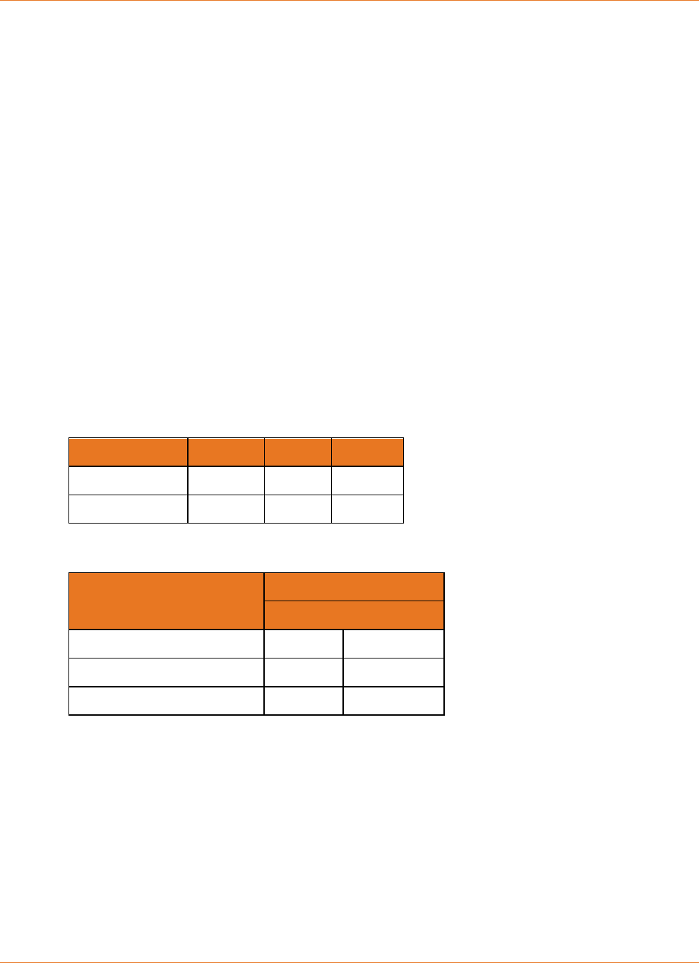
The default settings for Model 6 and newer are:
Temperature: Too Low OK Too Hot
Charging Disabled Enabled Disabled
Discharging Enabled Enabled Enabled
The following table shows the high and low temperature thresholds for disabling and re-
enabling charging and discharging for Model 6 and newer Telephony Modems:
Function
Threshold
Disabled Re-Enabled
Low Temp Charging ≤5°C ≥10°C
High Temp Charging ≥60°C ≤45°C
High Temp Discharging ≥75°C ≤65°C
Discharge protection is disabled by default, but can be enabled through provisioning. For
Model 6 and newer Telephony Modems, charging protection is always enabled. Use the
following MIB objects to control the battery discharge temperature protection feature.
arrisMtaDevPwrSupplyHiTempBatteryShutdownControl
(Model 6 and newer Telephony Modems) Enables or disables the high-temperature
battery shutdown function. This feature is disabled by default.
The valid settings for this object are:
disable
(0),
enable
(1).
When enabled, the Telephony Modem shuts off the battery when the battery
temperature exceeds 75°C ±10°. The Telephony Modem turns on the battery once battery
temperature has fallen to 65°C ±10°.

Chapter 5: Provisioning
STANDARD Revision 2.5 Touchstone Release 2.5 Reference Guide
© 2008-2016 ARRIS Enterprises LLC. All Rights Reserved. 39
Note 1: Consider carefully potential impacts before enabling the over-temperature
protection system. While the protection system may prevent battery damage, a
functioning Telephony Modem may shut down during an emergency situation and prevent
calls to emergency services.
Note 2: Use the arrisMtaDevPwrSupplyOverTempAlarmControl object to control over-
temperature behavior on Model 5 Telephony Modems.
arrisMtaDevPwrSupplyOverTempAlarmControl
Controls the battery over-temperature function for Model 5 Telephony Modems.
The valid settings for this object are:
•
disable
(0): (default for Model 5 Telephony Modems) Disables battery thermal
protection and the over-temperature alarm. Reading the
arrisMtaDevPwrSupplyTemperature object always returns "unavailable."
•
enable
(1): (default for Model 6 and newer Telephony Modems) Enables battery
thermal protection and the over-temperature alarm. Reading the
arrisMtaDevPwrSupplyTemperature object returns the current charger temperature.
Note that Model 6 and newer Telephony Modems disallow settings other than
enable
.
•
pendingenable
(2): (read-only) Battery thermal protection has been enabled but is
not yet active. This value may be seen immediately after enabling thermal protection
if there is some system delay.
•
pendingdisable
(3): (read-only) Battery thermal protection has been disabled but is
not yet inactive. This value may be seen immediately after disabling thermal
protection if there is some system delay.
Note 1: The setting for this object is not stored in non-volatile memory, so the feature is
disabled when the MTA is reset.
Note 2: Model 6 and newer Telephony Modems permanently set this object to
enable
(1),
since they do not allow the over-temperature alarm to be disabled.
arrisMtaDevPwrSupplyOverTempAlarmThreshold
Sets the over-temperature threshold. Valid range:
50
to
70
(degrees C). Default:
60
.
Note: The normal operating temperature for Touchstone eMTAs is 0°C to 50°C.

STANDARD Revision 2.5 Touchstone Release 2.5 Reference Guide
© 2008-2016 ARRIS Enterprises LLC. All Rights Reserved. 40
Chapter 6
Troubleshooting
This chapter discusses the available battery monitoring and charger troubleshooting
interfaces:
Logs and alarms
MIB objects
LED patterns
Logs and Alarms
Touchstone firmware provides a "Power Supply Telemetry" message through both the alarm
(SNMP TRAP) and log (Syslog) functionality.
Battery States
The following is a list of valid battery states for Telephony Modems with battery backup.
Normal—the Telephony Modem is operating on AC power, and is not in any of the other
states listed below.
Battery Replace—the Telephony Modem is operating on AC power, but the battery has
deteriorated below the tested capacity indicated by the
arrisMtaDevPwrSupplyConfigReplaceBatTime object. The battery should be replaced.
Battery Missing—the battery has been removed or has failed in such a way to appear to
be removed.
Telemetry Unavailable—indicates either a communication problem between the battery
charger and modem controller, or a general charger failure.
AC Fail Battery Low—the Telephony Modem is operating from battery power, and has
entered the "Battery Low" condition described above.
AC Fail Battery Replace—the Telephony Modem is operating from battery power. In
addition, the battery has deteriorated as described in "Battery Replace" above and should
be replaced.
AC Fail Battery Low Replace Battery—the Telephony Modem is operating from battery
power, and has entered the "Battery Low" condition described above. In addition, the
battery has deteriorated as described in "Battery Replace" above and should be replaced.
Power Supply Telemetry Alarm
Severity:
Major, non-service affecting

Chapter 6: Troubleshooting
STANDARD Revision 2.5 Touchstone Release 2.5 Reference Guide
© 2008-2016 ARRIS Enterprises LLC. All Rights Reserved. 41
Cause:
The eMTA has lost AC power or has encountered a problem in the battery charging
circuitry. The alarm includes one of the following battery status codes:
• AC Fail—the eMTA has detected an AC power failure.
• Charger Temperature High—the battery temperature alarm is enabled, and the
charger temperature has exceeded the temperature set either using the alarm CLI
command, or the arrisMtaDevPwrSupplyOverTempAlarmThreshold MIB object. This
alarm clears itself when the charger temperature falls to 10°C below the threshold
temperature.
Note: The normal operating temperature for Touchstone eMTAs is 0°C to 50°C.
• Charger OverTemp Shutdown—the battery high-temperature discharge protection
feature is enabled, and the charger temperature has exceeded the thresholds shown
in "see "Configuring Battery Temperature Protection (page 38)." The eMTA has shut
down the charger and disconnected the battery.
• Battery Mismatch—the battery installed is of the wrong type for the eMTA (for
example, an 8-cell battery pack installed in a TM502 or WTM552). The associated
Telemetry Log messages are "TELEMETRY NORMAL" and "BATTERY REPLACE." Remove
the battery to clear the alarm.
• Battery Charger Disabled—the eMTA has disabled the battery charger. Backup battery
power is not available. Power-cycle or reset the eMTA to re-enable the charger.
• Charger Download Failed—the eMTA has twice failed (initial attempt and one retry) to
download charger firmware. This indicates a hardware problem with the eMTA. The
battery charger is disabled and backup battery power is not available.
The logs provide more information about the battery status.
Impact:
None at time of alarm. Depending on the condition of the battery and the nature of the
power failure, the eMTA may exhaust the battery before AC power is restored.
Action:
Depends on the scope of the power outage.
Power Supply Telemetry Log
Event ID: 14
This event is used to report power supply related events, including state changes related to
battery functionality.
MIB Objects
The following battery-related MIB objects are supported in Touchstone firmware. See the
Touchstone Firmware Guide for your firmware version for complete details.

Chapter 6: Troubleshooting
STANDARD Revision 2.5 Touchstone Release 2.5 Reference Guide
© 2008-2016 ARRIS Enterprises LLC. All Rights Reserved. 42
Power-related MIB Objects
The CLAB-UPS-MIB lists RFC 1628 MIB objects that are required by PacketCable 1.5. ARRIS
implements a subset of this MIB, and provides more power-related information in the ARRIS-
MTA-DEVICE-MIB.
RFC 1628 MIB Objects
upsIdentManufacturer
The name of the UPS manufacturer. For Touchstone Telephony Modems, this object
always contains the string "ARRIS Interactive, L.L.C."
upsIdentModel
The model name or number of the UPS.
upsIdentAgentSoftwareVersion
The UPS agent software version.
upsIdentName
A customer-designated string identifying the UPS.
upsIdentAttachedDevices
A customer-designated string identifying devices attached to the UPS output.
upsBatteryStatus
The current battery charge status, one of:
•
batteryNormal
(2)—the remaining hold-up time is greater than the configured
upsConfigLowBattTime.
•
batteryLow
(3)—the remaining hold-up time is less than the configured
upsConfigLowBattTime.
•
batteryDepleted
(4)—if AC power is present, the battery does not have enough
charge to sustain the load if AC power is lost. If AC power is not present, shutdown is
imminent.
upsSecondsOnBattery
If the unit is on battery power, the elapsed time since the UPS last switched to battery
power, or the time since the network management subsystem was last restarted,
whichever is less. If AC power is present, this object returns
0
.
upsEstimatedMinutesRemaining
The estimated time, in minutes, to battery charge depletion under the current load
conditions if AC power is off and remains off, or if AC power were to be lost and remain
off. The accuracy of this and the following object depend on the eMTA completing a
capacity test.
Note: When AC power is present, the estimate is based on the typical idle power value,
not current load conditions.
upsEstimatedChargeRemaining
The estimated battery charge remaining, expressed as a percentage of full charge.
Chapter 6: Troubleshooting
STANDARD Revision 2.5 Touchstone Release 2.5 Reference Guide
© 2008-2016 ARRIS Enterprises LLC. All Rights Reserved. 43
upsInputNumLines
The number of input lines; also the number of rows in the upsInputTable.
upsOutputNumLines
The number of output lines; also the number of rows in the upsOutputTable.
upsAlarmsPresent
The number of active alarm conditions.
upsAlarmDescr
A reference to an alarm description object.
upsAlarmTime
Stores the sysUpTime value when the alarm condition was detected. A value of
0
indicates that the alarm condition was present before the eMTA’s SNMP agent started up.
upsConfigLowBattTime
Sets the low battery threshold, expressed in remaining minutes of holdup time. The initial
default value is 60 minutes for 2- or 4-cell batteries, or 120 minutes for 8-cell batteries.
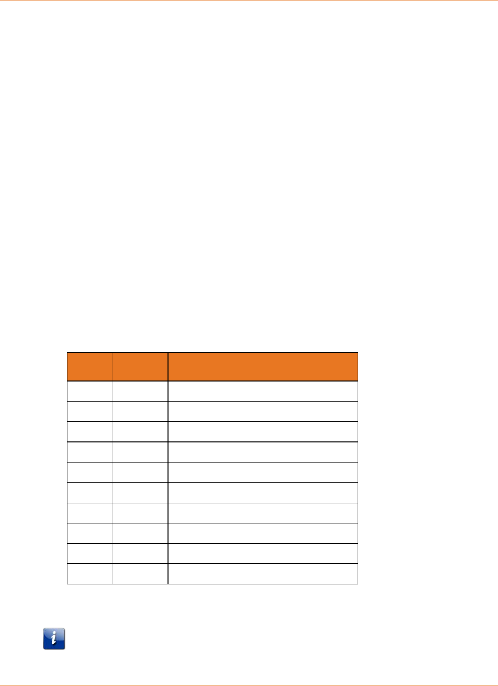
ARRIS Battery MIB Objects
arrisMtaDevBatteryOrderingCode
The ordering code of the installed battery. The following table lists the current battery
types:
Code Model # Description
718003 BPB022S 2.2Ah Battery
721944 BPB024S 2.4Ah Battery
789699 BPB026S 2.6Ah Battery
718005 BPB044S 4.4Ah Battery
722841 BPB044H 4.4Ah High-charge Battery
801190 BPB052H 5.2Ah High-charge Battery
785170 BPD066H 6.6Ah High-charge Battery
721192 BPB088S 8.8Ah Battery
722842 BPC088S Model 608 8.8Ah Battery
785171 BPD088H 8.8Ah High-charge Battery
The same information is available in the CM State troubleshooting web page. See the
Touchstone Firmware Guide for other information about the web interface.
Note: TS6.1 and newer versions of Touchstone firmware read the ordering code from the
battery EPROM. Batteries whose serial number begins with
1706
or higher have an
EPROM.

Chapter 6: Troubleshooting
STANDARD Revision 2.5 Touchstone Release 2.5 Reference Guide
© 2008-2016 ARRIS Enterprises LLC. All Rights Reserved. 44
Older firmware versions derive the ordering code from the rated battery capacity.
arrisMtaDevBatteryEprom
Contains manufacturing information about the battery. To read EPROM data, the
following must be true:
• The hardware must be Model 6 or newer, a TM504, or a TM502 manufactured after
November 2, 2006 (serial number begins with
6B2
).
• The battery pack must have an EPROM built in (serial number begins with
1706
or
higher).
arrisMtaDevBatteryChargerFWRev
The battery charger firmware revision.
arrisMtaDevPwrSupplyEnableDataShutdown
Enables or disables automatic shutdown of data services, but not telephony services, after
the Telephony Modem has been using battery power for a specified period of time. The
default value for this object is
enabled
(1). Set to
disabled
(2) to maintain data
communications during a power outage.
arrisMtaDevPwrSupplyEnableDataShutdownTime
Indicates the timeout period, in seconds, that the Telephony Modem continues to provide
data services after loss of AC power. The timer starts when the Telephony Modem loses
AC power. After the timer expires, the Telephony Modem shuts down data services
(Ethernet and USB) to conserve battery power. The default value for this object is
900
seconds (15 minutes).
arrisMtaDevPwrSupplyConfigReplaceBatTime
The replace battery threshold (i.e. the minimum acceptable battery capacity), expressed in
minutes of holdup time. If the tested battery capacity has degraded to a point where it
can no longer provide more than the specified amount of run-time, the eMTA raises a
Replace Battery alarm. The default value provides 1 hour of holdup time for 2- or 4-cell
batteries, or 2 hours for 8-cell batteries. You can change the threshold as needed, in
multiples of 5 minutes.
arrisMtaDevPwrSupplyBatteryTest
Controls scheduling of the battery test. See see "Scheduling Tests (page 37) for details.
arrisMtaDevPwrSupplyConfigRunTime
The provisioned battery hold-up time, in minutes, based upon the unit’s typical idle
power.
You can adjust the battery hold-up time using this value. Setting the hold-up time to a
lower value extends the total service life of the battery. Increasing the hold-up time in
turn decreases the total service life of the battery.
Setting this value greater than arrisMtaDevPwrSupplyBatAvailableMinutes does not
provide a run-time greater than arrisMtaDevPwrSupplyBatAvailableMinutes. This object
may be set only in multiples of 5 minutes.
arrisMtaDevPwrSupplyFullChargeTime
The time, in days, that the battery is charged and maintained at its maximum charge level.

Chapter 6: Troubleshooting
STANDARD Revision 2.5 Touchstone Release 2.5 Reference Guide
© 2008-2016 ARRIS Enterprises LLC. All Rights Reserved. 45
After this time has elapsed, the battery charge level is returned to the value specified by
arrisMtaDevPwrSupplyConfigRunTime.
Valid range:
1
to
16
(days).
arrisMtaDevPwrSupplyTemperature
The current charger temperature, in degrees C. This object is valid only when the
arrisMtaDevPwrSupplyOverTempAlarmControl object is enabled.
arrisMtaDevBatteryOperState
Current operational status of the Lithium-Ion battery pack:
unavailable
(0)
Indicates a possible charger failure. The charger and battery are disabled. Try:
o allowing the charger to reset itself (which may clear an illegal instruction
situation).
o power-cycling the Telephony Modem.
o upgrading the firmware.
if the state persists after the above actions, replace the unit.
invalid
(1)
(Model 4 only) Indicates a possible charger failure. See the actions for
unavailable
(0).
batteryReversedShorted
(3)
Unused.
batteryLowreplaceBatteryacFail
(4)
The Telephony Modem is running on battery power. The battery pack is low, and the
user should replace the battery pack.
batteryLowreplaceBattery
(5)
The battery pack is low, and the user should replace the battery pack.
batteryLowacFail
(6)
The Telephony Modem is running on battery power. In addition, the battery is low
(the calculated value of upsEstimatedMinutesRemaining has fallen below the value
set in upsConfigLowBattTime).
batteryLow
(7)
The battery is low (the calculated value of upsEstimatedMinutesRemaining has fallen
below the value set in upsConfigLowBattTime).
batteryMissing
(8)
The Telephony Modem cannot detect a battery. If a battery is present, make sure it is
inserted properly.
acFailreplaceBattery
(9)
The Telephony Modem is running on battery power. The user should replace the
battery pack.
replaceBattery
(10)
The tested battery capacity has degraded to a point where it can no longer provide a

Chapter 6: Troubleshooting
STANDARD Revision 2.5 Touchstone Release 2.5 Reference Guide
© 2008-2016 ARRIS Enterprises LLC. All Rights Reserved. 46
hold-up time greater than what is specified in the
arrisMtaDevPwrSupplyConfigReplaceBatTime object, or some other battery fault has
been detected, or an unsupported battery was installed. Replace the installed battery
for optimal battery-backup.
acFail
(11)
The Telephony Modem is running on battery power.
Note: Removing the battery during any AC Fail condition turns off the modem.
normal
(12)
The Telephony Modem is running on AC power. The battery and charger are
functioning properly.
testInProgress
(13)
The eMTA is testing the battery.
arrisMtaDevBatteryLastStateChange
The value of sysUpTime when the battery entered its current operational state. If the
current state has not changed since the eMTA last re-initialized, this object contains a zero
value.
arrisMtaDevBatteryOperSubState
A string containing the current sub-state of the battery, which provides more details about
the current operational status. See the table on the next page for details.
The current sub-state is not intended to match the arrisMtaDevBatteryOperState, but to
provide supplemental information indicating the current state of the battery.
arrisMtaDevPwrSupplyBatteryTestTime
The value of the battery test scheduler, in days. If the value is 0xFF (
255
), the scheduler
has been paused.
arrisMtaDevPwrSupplyReadBatteryPwr
The present load power, as an eight-second moving average, in 50-milliwatt units. When
AC power is not present, this is the power being removed from the battery. When the
eMTA is charging the battery, this is the power being applied.
arrisMtaDevPwrSupplySecondsOnBattery
The amount of time, in seconds, that the eMTA has been running on battery power.
arrisMtaDevPwrSupplyBatRatedMinutes
The estimated battery hold-up time, in minutes, based upon the typical idle power and the
rated capacity of the battery when fully charged. This is a fixed value based on the
capacity of a typical new battery.
arrisMtaDevPwrSupplyBatAvailableMinutes
The estimated available battery hold-up time, in minutes, based upon the typical idle
power and the tested capacity of the battery when fully charged. This value may change
after each battery test.
arrisMtaDevPwrSupplyHighestTemperature
A read-only string, containing the highest recorded battery charger temperature, in
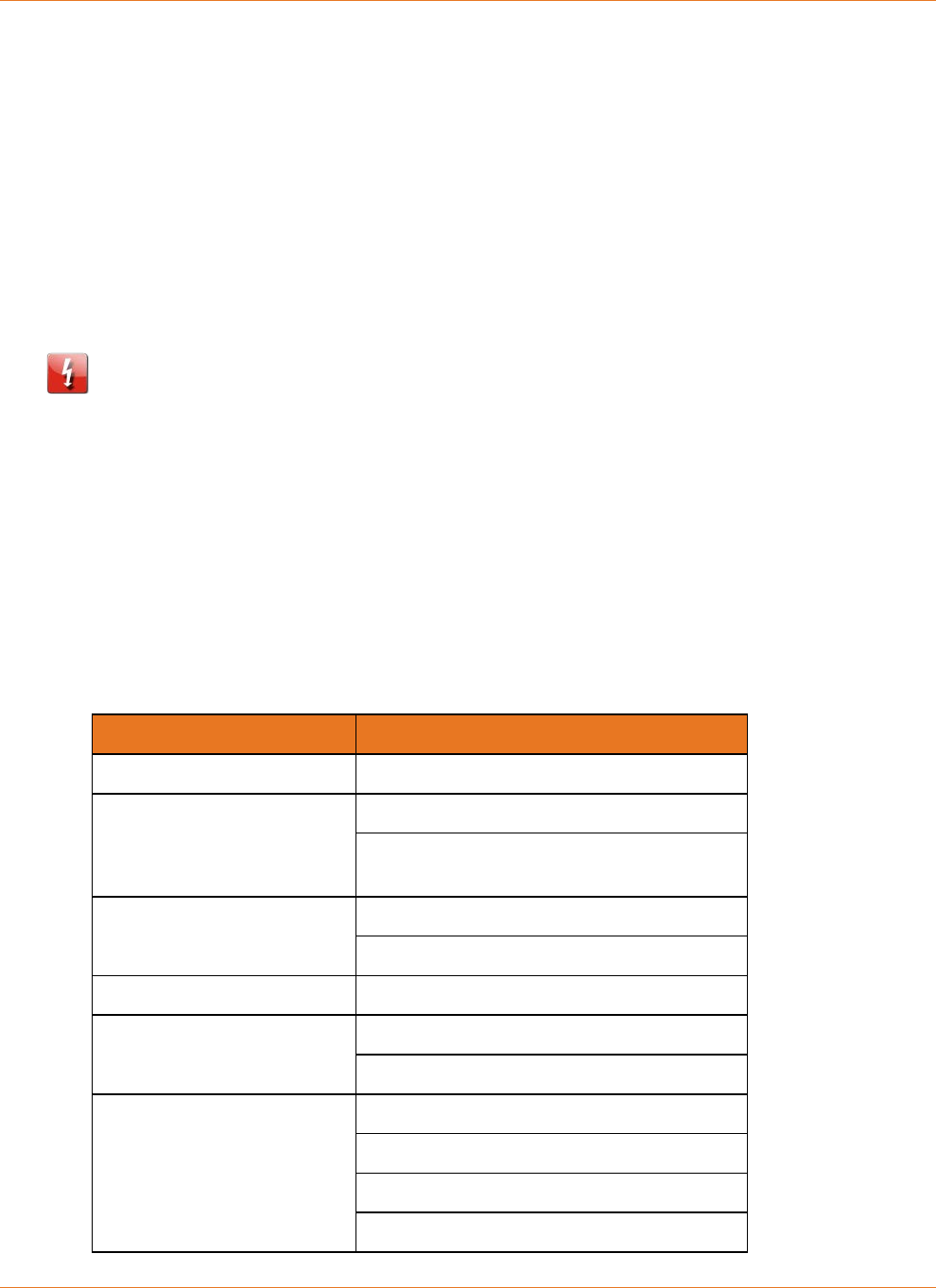
Chapter 6: Troubleshooting
STANDARD Revision 2.5 Touchstone Release 2.5 Reference Guide
© 2008-2016 ARRIS Enterprises LLC. All Rights Reserved. 47
degrees C. This is only available when arrisMtaDevPwrSupplyOverTempAlarmControl is
enabled.
arrisMtaDevPwrSupplyHighestTemperatureTime
A read-only string, displaying the time and date when the highest temperature was
recorded.
arrisMtaDevPwrSupplyHighestTemperatureClear
Set to
clear
(1) to clear the arrisMtaDevPwrSupplyHighestTemperature and
arrisMtaDevPwrSupplyHighestTemperatureTime objects. After clearing these objects,
their values become valid within 4 seconds, when the eMTA calculates the current
temperature.
CAUTION
Potential loss of service
Resetting the battery charger when the eMTA is in an AC Fail condition immediately shuts
down the eMTA.
arrisMtaDevPwrSupplyControlChargerReset
Set this object to
true
(1) to reset the battery charger.
SNMP Battery Telemetry States
Battery telemetry states can be completely described by using the
arrisMtaDevBatteryOperState and arrisMtaDevBatteryOperSubState MIB objects. The
following table shows which sub-states are associated with each state.
State Sub-State
unavailable
(0) Charger Failure
batteryLow-
replaceBattery-
acFail
(4)
AC-Fail & Replace Bat & Bat Low
Test is Pending, AC-Fail, Replace Battery,
Battery Low
batteryLow-acFail
(6)
AC-Fail & Battery Low
Test is Pending, AC-Fail, Battery Low
batteryMissing
(8) Battery Missing
acFail-
replaceBattery
(9)
AC-Fail & Replace Battery
Test is Pending, AC-Fail, Replace Battery
replaceBattery
(10)
Battery OFF & Replace Battery
Replace Battery
Replace Battery & Battery Low
Battery is Charging & Replace Battery

Chapter 6: Troubleshooting
STANDARD Revision 2.5 Touchstone Release 2.5 Reference Guide
© 2008-2016 ARRIS Enterprises LLC. All Rights Reserved. 48
State Sub-State
unavailable
(0) Charger Failure
Battery is Charging & Replace Battery &
Battery Low
Battery Test Load ON & Replace Battery
Battery Test Load ON & Replace Battery &
Battery Low
Test in Progress, Replace Battery
Test in Progress, Replace Battery, Battery
Low
Test in Progress, Battery is Charging & Rpl
Bat
Test in Progress, Battery is Charging & Rpl
Bat & Bat Low
Test is Pending, Replace Battery
Test is Pending, Replace Battery, Battery
Low
Test is Pending, Battery is Charging & Rpl
Bat
Test is Pending, Battery is Charging & Rpl
Bat & Bat Low
Battery OFF & Replace Battery & Battery
Low
acFail
(11)
AC-Fail
Test is Pending, AC-Fail
normal
(12)
Battery is Turned OFF
Battery Backup Normal
Battery Low
Battery is Charging & Backup is Normal
Battery is Charging & Battery Low
Battery Test Load ON & Backup is Normal
Battery Test Load ON & Battery Low
Test in Progress
Test in Progress, Battery Low
Test in Progress, Battery is Charging
Chapter 6: Troubleshooting
STANDARD Revision 2.5 Touchstone Release 2.5 Reference Guide
© 2008-2016 ARRIS Enterprises LLC. All Rights Reserved. 49
State Sub-State
unavailable
(0) Charger Failure
Test in Progress, Battery is Charging & Bat
Low
Test is Pending
Test is Pending, Battery Low
Test is Pending, Battery is Charging
Test is Pending, Battery is Charging & Bat
Low
testInProgress
(13)
Test in Progress, Battery Test Load ON
Test in Progress, Battery Test Load ON & Rpl
Bat
Test in Progress, Battery Test Load ON &
Bat Low
Test in Progress, Battery Test Load ON & Rpl
Bat & Bat Low
Web-based Troubleshooting Interface
Telephony Modems provide a web-based troubleshooting interface that can be accessed from
either the CM or MTA IP addresses.
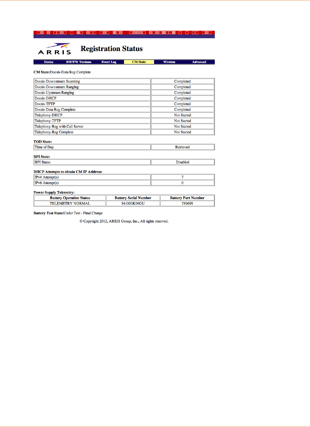
Chapter 6: Troubleshooting
STANDARD Revision 2.5 Touchstone Release 2.5 Reference Guide
© 2008-2016 ARRIS Enterprises LLC. All Rights Reserved. 50
The Registration Status screen displays the current battery telemetry state and serial number.
To display this screen, choose the CM State link.
The last two sections of this page provide information about the charging system, as described
below.
Power Supply Telemetry Field
The Power Supply Telemetry section provides the following information:
Battery Operation Status
The operational status of the charging system:
TELEMETRY NORMAL
The battery and charging system are functioning normally.
BATTERY MISSING
Either no battery is installed, or the battery has completely failed.
AC FAIL
The Touchstone device is running on battery power, but otherwise functioning
normally.
AC FAIL BATTERY LOW
The Touchstone device is running on battery power, but the battery charge level is
below a pre-defined charge level.
BATTERY REPLACE
The tested battery capacity is below 80% of its rated capacity and should be replaced

Chapter 6: Troubleshooting
STANDARD Revision 2.5 Touchstone Release 2.5 Reference Guide
© 2008-2016 ARRIS Enterprises LLC. All Rights Reserved. 51
as soon as possible. If the battery is less than a year old, it might be replaced under
warranty.
AC FAIL BATTERY REPLACE
The Touchstone device is running on battery power. The tested battery capacity is
below 80% of its rated capacity, and thus may not be able to provide the rated hold-up
time.
AC FAIL BATTERY LOW REPLACE
The Touchstone device is running on battery power. The tested battery capacity is
below 80% of its rated capacity, and the battery charge level is below a pre-defined
charge level.
BATTERY TEST IN PROGRESS
The Touchstone device is testing its battery. This happens every six months (or the
cable operator can set a different interval). The battery may not be able to provide its
rated hold-up time if AC power fails during the test. When this state is active, the
Battery Test State field shows the progress of the test.
TELEMETRY UNAVAILABLE
Wait a few minutes, then refresh the page. If this state persists, call your cable
operator support for assistance.
No Status Reported
The charging system has been disabled. Try resetting the device to clear this issue. If
that does not work, power-cycle the device. If this state persists, call your cable
operator support for assistance.
Invalid Code from Charger
Wait a few minutes, then refresh the page. If this state persists, the battery may have
a problem.
Battery Serial Number
The battery serial number is available on most Telephony Modems. The following is a list
of other messages that may appear in the Battery Serial Number field:
Battery Serial Number Not Supported
The Telephony Modem is an early Model 5 Telephony Modem, or another non-
supported modem or battery pack.
Battery Missing
No battery is installed.
AC Failed. S/N Temporarily Unavailable
The Telephony Modem is running on battery power, and has disabled reading the
battery serial number as part of the data services shutdown function to conserve
power. Not all Telephony Modems disable reading the battery serial number upon
data shutdown (for example, Model 7 Telephony Modems).
Unable to obtain Battery Serial Number(s)
Appears in cases where the serial number is missing or unreadable.

Chapter 6: Troubleshooting
STANDARD Revision 2.5 Touchstone Release 2.5 Reference Guide
© 2008-2016 ARRIS Enterprises LLC. All Rights Reserved. 52
Battery Part Number
The ordering code of the installed battery.
If the Battery Part Number is "Contact ARRIS," the battery is either defective or the Telephony
Modem has an unsupported battery installed (for example, a model BPB088S battery installed
in a TM502).
Battery Test State Field
The Battery Test State field indicates whether the charging system is testing the battery; and if
so, the current progress of the test. This field provides one of the following indications:
Not Currently Under Battery Test
The normal operating state.
Under Test - Initial Charge
The battery is being charged to full capacity to begin the test.
Under Test - Initial Discharge
The battery was fully charged, and the E-UE is now running on battery power.
Under Test - Final Charge
The battery was fully charged, then discharged, and now the E-UE is charging the battery
to its operational capacity.
LEDs
The Power LED and Battery LED provide a quick indication of power and battery status. The
following table describes LED behavior for each power status.
TM502/504/602/WTM552/652 LED Status
Power
Mode
LED
Power Battery
AC Power Good On
On: battery good or low
Off: battery not installed
Flash: replace battery
AC Power Fail Flash
On: battery good
Flash: battery bad or low
Chapter 6: Troubleshooting
STANDARD Revision 2.5 Touchstone Release 2.5 Reference Guide
© 2008-2016 ARRIS Enterprises LLC. All Rights Reserved. 53
TM7xx/TM8xx/TG852/TG16xx/TG2472 LED Status
Note: See sections following for TG862 and TM1602 LED status.
Power
Mode
LED
Power Battery
AC Power Good On
On: battery good or low
Off: battery not installed
Flash: replace battery
AC Power Fail Flash
Off: battery good or low
Flash: replace battery
TG862 LED Status
Power
Mode
LED
Power Battery
AC Power Good On
On: battery good or low
Off: battery not installed
Flash: replace battery
AC Power Fail Flash
On: battery good or low
Flash: replace battery
Chapter 6: Troubleshooting
STANDARD Revision 2.5 Touchstone Release 2.5 Reference Guide
© 2008-2016 ARRIS Enterprises LLC. All Rights Reserved. 54
TM1602/TM3202 LED Status
Power
Mode
LED
Power Battery
AC Power Good On
On: battery good or low
Off: battery not installed
Flash: replace battery
AC Power Fail Flash
Off: battery good
Flash: replace battery or battery
low
Battery Mismatch
When an unsupported battery is inserted in a Telephony Modem (for example, a model
BPB088S battery inserted in a TM502 or WTM552), it repeats the following sequence:
Battery LED on, all others off
Battery LED off, all others on
The MTA also sets a "Battery Mismatch" alarm. To clear this issue, replace the battery with
one of the proper type.
Performing Hold-up Testing
Use this procedure to test Telephony Modem hold-up times. The hold-up times shown in "see
"Estimated Hold-up Times by Model" are reasonably accurate for the conditions specified; you
may wish to test hold-up times with a different set of initial conditions.
See Charger Initialization Times for the total time needed for charger initialization and battery
tests for each model and battery type.
Requirements
Actual requirements for a hold-up test depend on the conditions you wish to set up. The
Telephony Modem must be ranged and registered, with the appropriate battery inserted
before powering on the modem. If you are planning to test hold-up times with lines off-hook,
you need to connect telephones to the Telephony Modem.
An SNMP browser is useful but not strictly necessary; you can use it to display battery and
charger status during the hold-up test.

Chapter 6: Troubleshooting
STANDARD Revision 2.5 Touchstone Release 2.5 Reference Guide
© 2008-2016 ARRIS Enterprises LLC. All Rights Reserved. 55
If you want to run the test with different parameters such as data shutdown times or changing
MIB objects that control charger behavior, you need to set up a configuration file with the
desired changes.
Temperature-related tests may require an environmental chamber.
Action
Follow these steps to test hold-up times.
1. Prepare the Telephony Modem:
1. Install the battery.
2. Connect as many telephones as necessary to test hold-up times with activity.
3. Connect RF and (if needed) Ethernet or USB.
4. Apply AC power and allow the Telephony Modem to range and register.
2. Verify that the Telephony Modem has started its battery test cycle using one of the
following methods:
• Check the event log for a "Power Supply Telemetry Log - Battery Test in Progress"
message. You can use SNMP or the web-based interface (see the "Event Log" page) to
display the event log.
• Using SNMP, check the status of the arrisMtaDevBatteryOperState object. The object
value should be
testInProgress
(13).
3. Wait for the Telephony Modem to complete its initial charger initialization and battery
test. See "Charger Initialization Times" above for the time required.
When the test is complete, the Telephony Modem adds a "Power Supply Telemetry Log -
Telemetry Normal" message to the event log and sets the value of the
arrisMtaDevBatteryOperSubState object to
BatteryBackupNormal
.
Note 1: If the charger status is not
BatteryBackupNormal
, replace the battery (or the
Telephony Modem) and start the test again.
Note 2: Begin the hold-up test within 24 hours after the battery test cycle completes (the
charger status reads
BatteryBackupNormal
).
4. Place unit in the desired mode:
• Idle mode: all lines on hook and no transmit or receive data traffic.
• Talk mode: one or more lines off-hook with no data traffic.
5. Remove AC power.
Note: When testing in Talk mode, verify that the call is not dropped when removing AC
power.
6. Record the length of time that it takes for the battery to completely discharge (all LEDs
turn off).

Chapter 6: Troubleshooting
STANDARD Revision 2.5 Touchstone Release 2.5 Reference Guide
© 2008-2016 ARRIS Enterprises LLC. All Rights Reserved. 56
If practical, read and record upsEstimatedMinutesRemaining and upsSecondsOnBattery
values at 15-minute intervals. When the Telephony Modem logs a "Battery Low" message,
read and record data at 1-minute intervals.
Expected Results:
• The Telephony Modem should operate for the times specified in above, while running
on battery, adjusted for configuration changes. See "see "Factors Affecting Hold-up
Times (page 25)" for selected effects on hold-up time.
• The final value of upsSecondsOnBattery should be approximately equal to the actual
recorded time.
• Comparing the sampled upsEstimatedMinutesRemaining times to the actual time
remaining should match within ±5%.
Note: Any change in load (for example, taking a line off-hook or hanging up) has an
immediate effect on the value of upsEstimatedMinutesRemaining. While the value should
accurately reflect the remaining time under current load conditions, keeping the load
constant minimizes fluctuations in the reported value.

STANDARD Revision 2.5 Touchstone Release 2.5 Reference Guide
© 2008-2016 ARRIS Enterprises LLC. All Rights Reserved. 57
Chapter 7
Extended Outage Handling
While most power outages are brief, some outages can last for hours or over a day. This
chapter provides tips for maximizing hold-up times during extended outages.
For the purpose of this manual, the duration of an "extended outage" is at least as long as the
typical estimated hold-up time for the normal customer installation in your network. See "see
"Estimated Hold-up Times by Model" for a list of typical hold-up times for each Telephony
Modem model.
Note: Subscribers that want extended hold-up times may order spare or higher-capacity
batteries from http://www.yourbroadbandstore.com (http://shop.surfboard.com/).
Battery Charge Data
You can use the following MIB objects to check the current and potential battery charge status
of any Telephony Modem.
arrisMtaDevPwrSupplyBatRatedMinutes
The estimated battery hold-up time, in minutes, based upon the typical idle power and the
rated capacity of the battery when fully charged. This is a fixed value based on the
capacity of a typical new battery.
arrisMtaDevPwrSupplyBatAvailableMinutes
The estimated available battery hold-up time, in minutes, based upon the typical idle
power and the tested capacity of the battery when fully charged. This value may change
after each battery test.
arrisMtaDevPwrSupplyConfigRunTime
The provisioned battery hold-up time, in minutes, based upon the unit’s typical idle
power.
Setting this value greater than arrisMtaDevPwrSupplyBatAvailableMinutes does not
provide a run-time greater than arrisMtaDevPwrSupplyBatAvailableMinutes. This object
may be set only in multiples of 5 minutes.
upsEstimatedMinutesRemaining
The estimated time, in minutes, to battery charge depletion under the current load
conditions if AC power is off and remains off, or if AC power were to be lost and remain
off. The accuracy of this and the following object depend on the eMTA completing a
capacity test.
Note: When AC power is present, the estimate is based on the typical idle power value,
not current load conditions.

Chapter 7: Extended Outage Handling
STANDARD Revision 2.5 Touchstone Release 2.5 Reference Guide
© 2008-2016 ARRIS Enterprises LLC. All Rights Reserved. 58
Preparing for Extended Outages
In many cases, you can anticipate and prepare for weather-related outages. Weather events
that can cause extended outages include:
hurricanes (or other high winds)
severe thunderstorms
ice storms/blizzards
heat waves
The following techniques may be useful to maximize hold-up times during an anticipated
extended outage. When changing MIB objects, making the same changes in a configuration
file ensures that subscribers do not inadvertently revert the settings by power-cycling the
Telephony Modem.
Setting Full Charge
Set the arrisMtaDevPwrSupplyFullChargeTime object to the number of days that you wish to
charge and maintain the battery at 100% of its rated voltage. Valid range:
1
to
16
days.
Note: The Telephony Modem disables battery testing during this period.
Charging Replacement Batteries
A bank of Telephony Modems can be employed to pre-charge quantities of batteries to be
used in battery swaps during the outage. The modems should be provisioned as described
above to charge the batteries completely and to disable battery testing.
Servicing Customers During Extended Outages
Some MSOs provide battery swaps to subscribers during extended power outages. The
following tips may be helpful to facilitate battery swaps.
Model 6 and newer products can be started from the backup battery by installing a
charged battery and pressing the Reset button on the back on the modem. Use a pointed,
non-metallic tool to press the Reset button.
Model 5 Telephony Modems do not support the "boot from battery" feature. However,
you can plug these modems into an external AC source to start them. Once the modem
begins ranging, you can disconnect it from the AC source.

STANDARD Revision 2.5 Touchstone Release 2.5 Reference Guide
© 2008-2016 ARRIS Enterprises LLC. All Rights Reserved. 59
Chapter 8
Appendix A: Ordering Codes
ARRIS provides the following backup battery packs. The following tables show which devices
are compatible with each battery type.
Battery
Model
Telephony Modem/Telephony Gateway
502 504 552 602 604 608 652
BPB022S ✓ ✓ ✓ ✓ ✓ - ✓
BPB024S ✓ ✓ ✓ ✓ ✓ - ✓
BPB026S ✓ ✓ ✓ ✓ ✓ - ✓
BPB044S ✓ ✓ ✓ ✓ ✓ ✓ ✓
BPB044H ✓ ✓ ✓ ✓ ✓ ✓ ✓
BPB052H ✓ ✓ ✓ ✓ ✓ ✓ ✓
BPD066H - - - - - - -
BPB088S - ✓ - ✓ ✓ - ✓
BPC088S - - - - - ✓ -
BPD088H - - - - - - -
Battery
Model
Telephony Modem/Telephony Gateway
702 722 802 804 822 852 862
BPB022S ✓ ✓ ✓ ✓ ✓ ✓ ✓
BPB024S ✓ ✓ ✓ ✓ ✓ ✓ ✓
BPB026S - - ✓ ✓ ✓ ✓ ✓
BPB044S ✓ ✓ ✓ ✓ ✓ ✓ ✓
BPB044H ✓ ✓ ✓ ✓ ✓ ✓ ✓
BPB052H ✓ ✓ ✓ ✓ ✓ ✓ ✓
BPD066H - ✓ ✓ ✓ ✓ - -
BPB088S - - - ✓ ✓ - ✓
BPC088S - - - - - - -
BPD088H - ✓ ✓ ✓ ✓ - -

Chapter 8: Appendix A: Ordering Codes
STANDARD Revision 2.5 Touchstone Release 2.5 Reference Guide
© 2008-2016 ARRIS Enterprises LLC. All Rights Reserved. 60
Battery Model Gateway
1602 1652 1662 1672 1682 2402 2472 3202
BPB022S ✓ ✓ ✓ ✓ ✓ ✓ ✓ xxx
BPB024S ✓ ✓ ✓ ✓ ✓ ✓ ✓
BPB026S ✓ ✓ ✓ ✓ ✓ ✓ ✓
BPB044S ✓ ✓ ✓ ✓ ✓ ✓ ✓
BPB044H ✓ ✓ ✓ ✓ ✓ ✓ ✓
BPB052H ✓ ✓ ✓ ✓ ✓ ✓ ✓
BPD066H - - - - - - -
BPB088S - - - - - - -
BPC088S - - - - - - -
BPD088H - - - - - - -
Battery
Model
Media Gateway
5125 5225 6125 6225 6325 6425
BPB022S - - ✓ ✓ ✓ ✓
BPB024S - - ✓ ✓ ✓ ✓
BPB026S - - ✓ ✓ ✓ ✓
BPB044S ✓ ✓ ✓ ✓ ✓ ✓
BPB044H ✓ ✓ ✓ ✓ ✓ ✓
BPB052H ✓ ✓ ✓ ✓ ✓ ✓
BPD066H - - - - - -
BPB088S - - - - - -
BPC088S ✓ ✓ - - - -
BPD088H - - - - - -
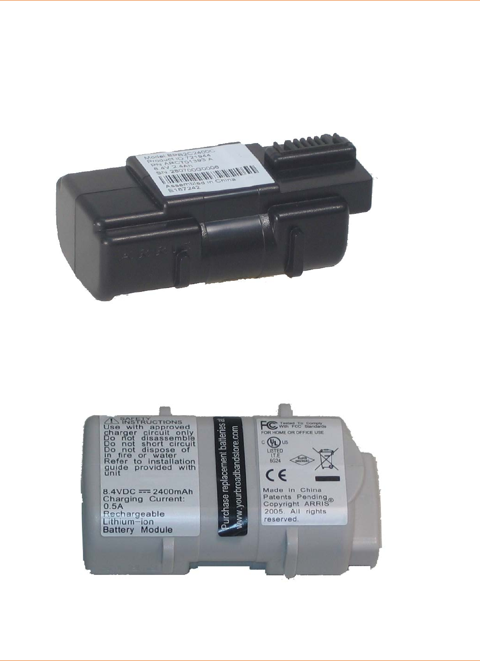
Chapter 8: Appendix A: Ordering Codes
STANDARD Revision 2.5 Touchstone Release 2.5 Reference Guide
© 2008-2016 ARRIS Enterprises LLC. All Rights Reserved. 61
2-cell Batteries
Model BPB022S 2.2 Ah battery pack ordering codes:
10-pack: 718003
Single: 790513
Model BPB024S ordering codes:
10-pack: 721944
Single: 790515
Model BPB026S ordering codes:
10-pack: 789699
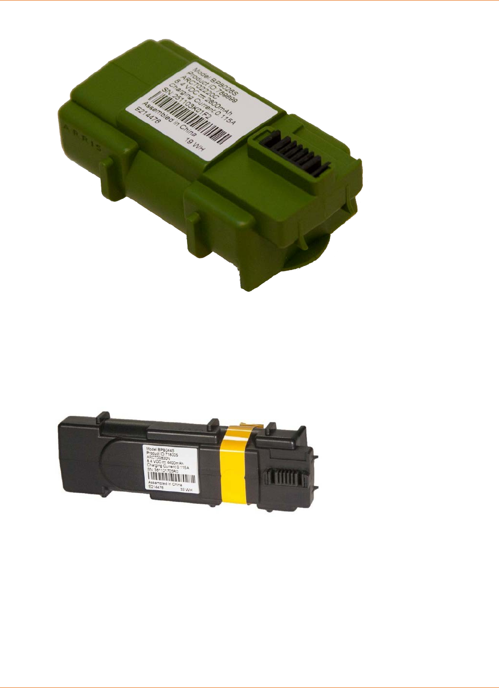
Chapter 8: Appendix A: Ordering Codes
STANDARD Revision 2.5 Touchstone Release 2.5 Reference Guide
© 2008-2016 ARRIS Enterprises LLC. All Rights Reserved. 62
Single: 794068
4-cell Batteries
Model BPB044S ordering codes:
10-pack: 718005
Single: 790512
Model BPB044H ordering codes:
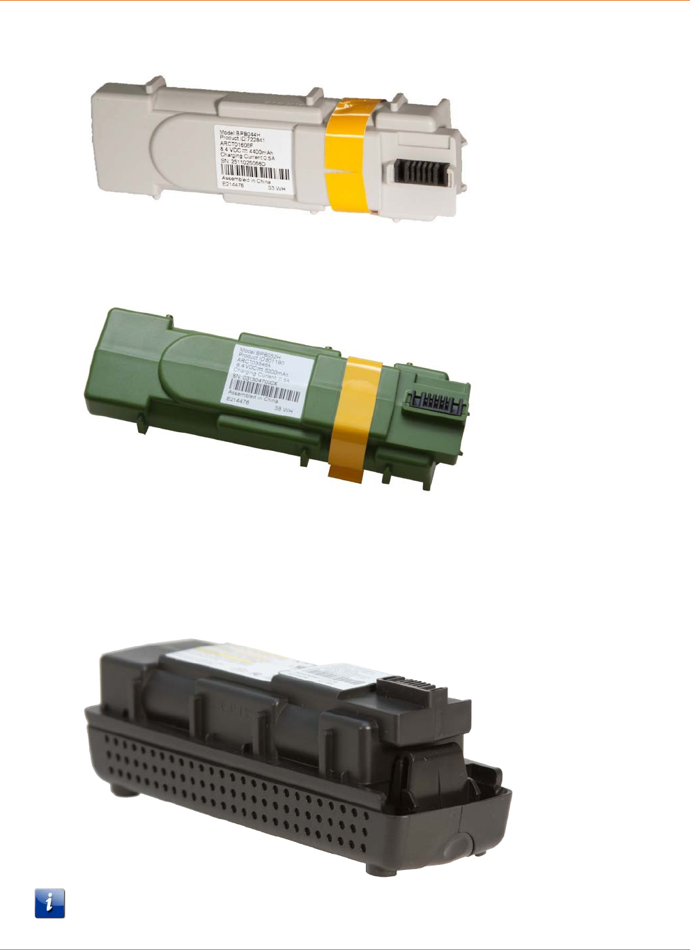
Chapter 8: Appendix A: Ordering Codes
STANDARD Revision 2.5 Touchstone Release 2.5 Reference Guide
© 2008-2016 ARRIS Enterprises LLC. All Rights Reserved. 63
10-pack: 722841
Model BPB052H ordering codes:
10-pack: 801190
6-cell Battery
Model BPD066H ordering codes:
10-pack: 785170
Note: The BPD066H 6-cell battery is compatible only with the TM722, Model 8 (TM802,
TM804, TM822), and TM1602 Telephony Modems.
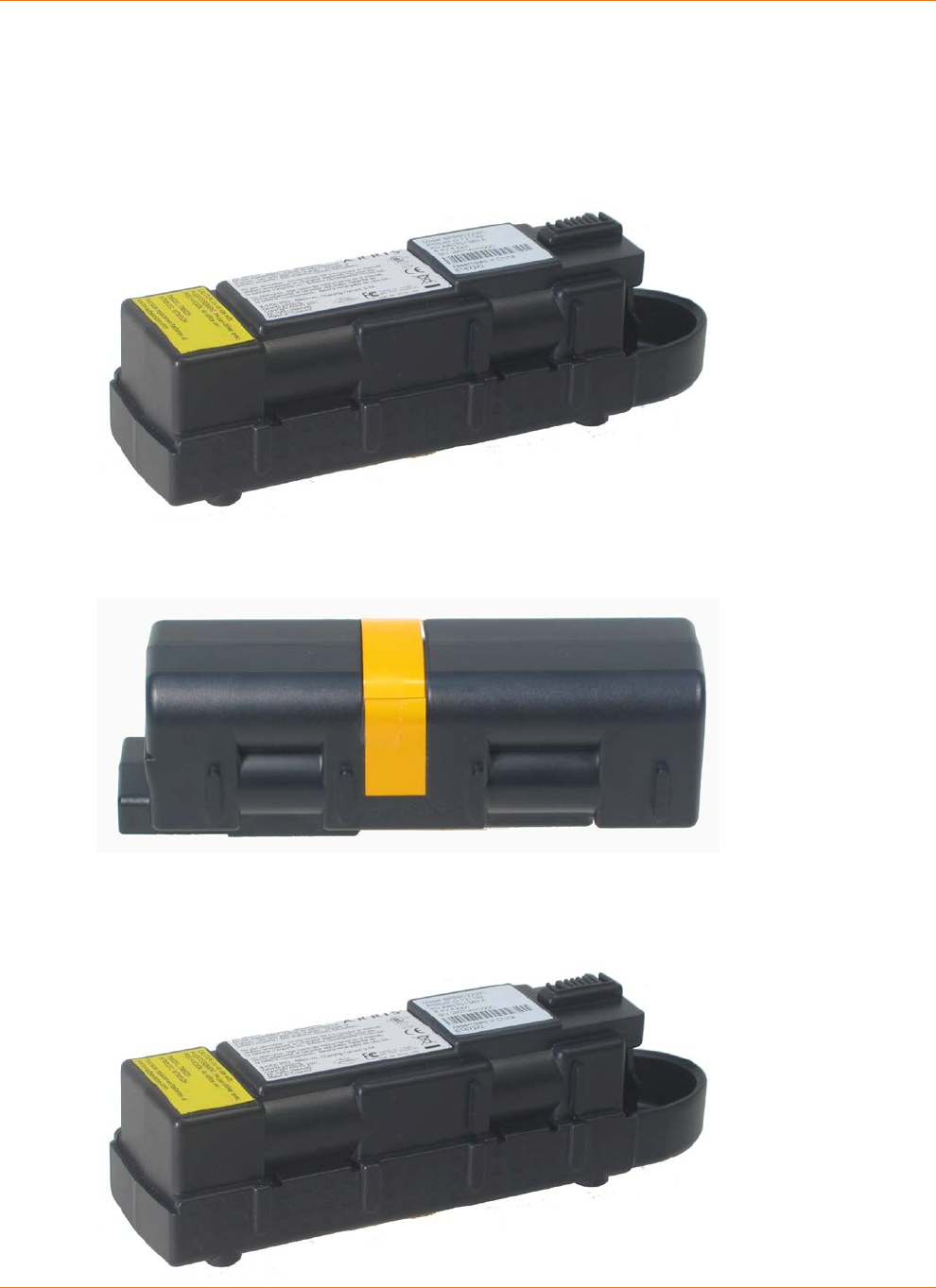
Chapter 8: Appendix A: Ordering Codes
STANDARD Revision 2.5 Touchstone Release 2.5 Reference Guide
© 2008-2016 ARRIS Enterprises LLC. All Rights Reserved. 64
8-cell Battery
Model BPB088S ordering codes:
10-pack: 721192
Single: 790514
Model BPC088S ordering codes:
10-pack: 722842
Model BPD088H ordering codes:
10-pack: 785171
Single: 802251

Chapter 8: Appendix A: Ordering Codes
STANDARD Revision 2.5 Touchstone Release 2.5 Reference Guide
© 2008-2016 ARRIS Enterprises LLC. All Rights Reserved. 65
Note 1: The BPB088S 8-cell battery replaces the battery bay door on the bottom of the
Telephony Modem, and increases the height of the Telephony Modem by about 5/8 inch
(16 mm).
Note 2: The BPB088S 8-cell battery is compatible only with the TM504, and Model 6 (except
TM608) Telephony Modems. The battery fits physically in TM502 and WTM552 modems, but
installation in these modems results in a "Battery Mismatch" alarm. Use the BPC088S 8-cell
battery in a TM608 multi-line Telephony Modem.
Note 3: The BPD088H 8-cell battery is compatible only with the TM722, Model 8 (TM802,
TM804, TM822), and TM1602 Telephony Modems.

Corporate Headquarters
ARRIS · Suwanee · Georgia · 30024 · USA
T: 1-678-473-2000 F: 1-678-473-8470
www.arris.com
