Aruba Networks APIN0228 Wireless Access Point User Manual AP 228 IG Rev 02
Aruba Networks, Inc. Wireless Access Point AP 228 IG Rev 02
Contents
- 1. AP228_datasheet
- 2. User guide_1
User guide_1
AP-228 Wireless Access Point
Installation Guide
0511728-02 | February 2015 1
The Aruba AP-228 is a fully temperature hardened, water resistant, indoor rated, dual-radio IEEE
802.11ac wireless access point. This access point use MIMO (Multiple-in, Multiple-out) technology and
other high-throughput mode techniques to deliver high-performance, 802.11ac 2.4 GHz and 5 GHz
functionality while simultaneously supporting existing 802.11a/b/g/n wireless services. The AP-228
access point works only in conjunction with an Aruba Controller.
AP-228 Operations
Wireless transceiver
Wireless access point (IEEE 802.11 a/b/g/n/ac)
Wireless air monitor (IEEE 802.11 a/b/g/n/ac)
Protocol-independent networking functionality
Compatibility with IEEE 802.3at PoE
Central management configuration and upgrades with an Aruba Controller.
Guide Overview
“AP-228 Hardware Overview” on page3 provides a detailed hardware overview of the AP-228.
“Before You Begin” on page5 provides key questions to ask and items to consider when deploying
a wireless network.
“Installing the AP” on page7 describes the multi-step process for a successful installation and
deployment of the AP-228.
“Safety and Regulatory Compliance” on page12 provides an overview of safety and regulatory
compliance information.
Package Contents
AP-228 Access Point
Cable Glands x2
USB Console Cable
Copper Lug x1
M4 x 6 Screw x1
Installation Guide (this document)
The weatherproof caps for Ethernet and Console interfaces are connected to the AP, not loose in the package.
Mounting kits for use with the AP-228 access points are sold separately. Contact your Aruba sales
representative for details.

2AP-228 Wireless Access Point | Installation Guide
Inform your supplier if there are any incorrect, missing, or damaged parts. If possible, retain the carton,
including the original packing materials. Use these materials to repack and return the unit to the supplier if
needed.
AP-228 Wireless Access Point | Installation Guide 3
AP-228 Hardware Overview
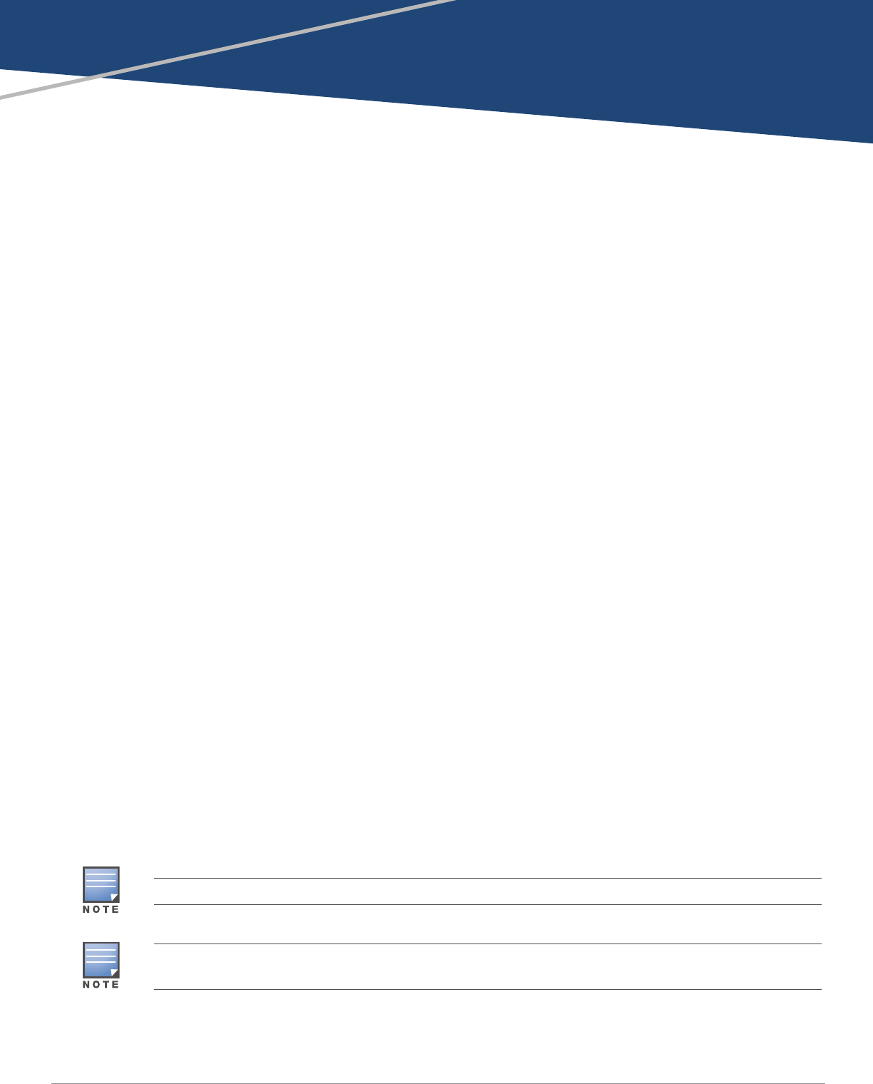
Figure 1 AP-228 Front View
Figure 2 AP-228 Bottom View
LED
The AP-228 is equipped with one LED that indicates the system status of the AP.
Table 1 AP-228 LED Meanings during Boot Up
LED Color/State Meaning
System LED Off No power to AP
Red Initial power-up
Green - Flashing AP booting
Green - Steady AP ready and 1000Mbps Ethernet link established. The LED
turns off after 1200 seconds
Green - Yellow, 6 seconds
period AP ready and 10/100Mbps Ethernet link established. The LED
turns off after 1200 seconds
2G0
2G1
2G2
5G0
5G1
5G2
LAN
WAN
Grounding Point
USB Console Port, Reset button and LED
4AP-228 Wireless Access Point | Installation Guide
Table 2 AP-228 LED Meanings during Operation
USB Console Port
The USB Micro-B console port allows you to connect the AP to a terminal or a laptop for direct local
management. Use the included USB console cable to connect the AP. You can download the
necessary driver for USB-UART adapter from support.arubanetworks.com under the Tools &
Resources tab.
Use the following setting to access the terminal:
Ethernet Ports
AP-228 is equipped with two10/100/1000Base-T (RJ-45) Gigabit Ethernet ports (WAN and LAN port)
for wired network connectivity. The WAN port supports 802.3at Power over Ethernet (PoE), accepting
48 VDC (nominal) as a standard defined Powered Device (PD) from a Power Sourcing Equipment (PSE)
such as a PoE midspan injector.
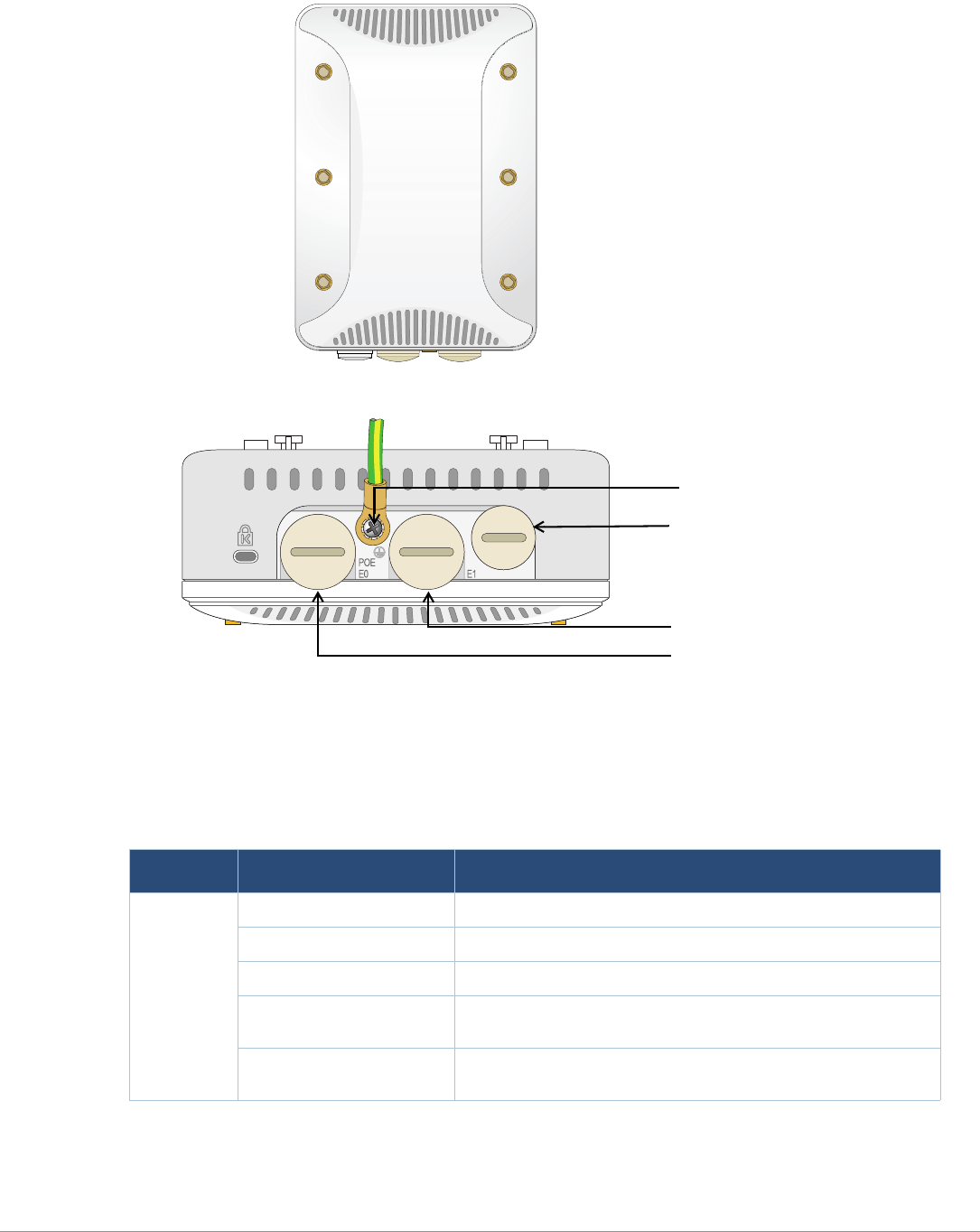
These ports have RJ-45 female connectors with the pin-outs shown in Figure 3.
Figure 3 Gigabit Ethernet Port Pin-Out
Reset Button
The reset button can be used to return the AP to factory default settings. To reset the AP:
1. Power off the AP.
2. Press and hold the reset button using a small, narrow object, such as a paperclip.
3. Power-on the AP without releasing the reset button. The system LED will flash within 5 seconds.
4. Release the reset button.
The system LED will flash again within 15 seconds indicating that the reset is completed. The AP will
now continue to boot with the factory default settings.
LED Color/State Meaning
System LED Solid Red General fault
One blink off every 3
seconds Radio 0 fault (5 GHz)
Two quick blink off 0.5
seconds apart cycled every
3 seconds
Radio 1 fault (2.4GHz)
Table 3 Console Settings
Baud Rate Data Bits Parity Stop Bits Flow Control
9600 8 None 1 None
1000Base-T Gigabit
Ethernet Port
RJ-45 Female
Pin-Out
Signal Name
1
2
3
4
5
6
7
8
BI_DC+
BI_DC-
BI_DD+
BI_DD-
BI_DA+
BI_DA-
BI_DB+
BI_DB-
Function
Bi-directional pair +C, POE Positive
Bi-directional pair -C, POE Positive
Bi-directional pair +D, POE Negative
Bi-directional pair -D, POE Negative
Bi-directional pair +A, POE Negative
Bi-directional pair -A, POE Negative
Bi-directional pair +B, POE Positive
Bi-directional pair -B, POE Positive
AP-228 Wireless Access Point | Installation Guide 5
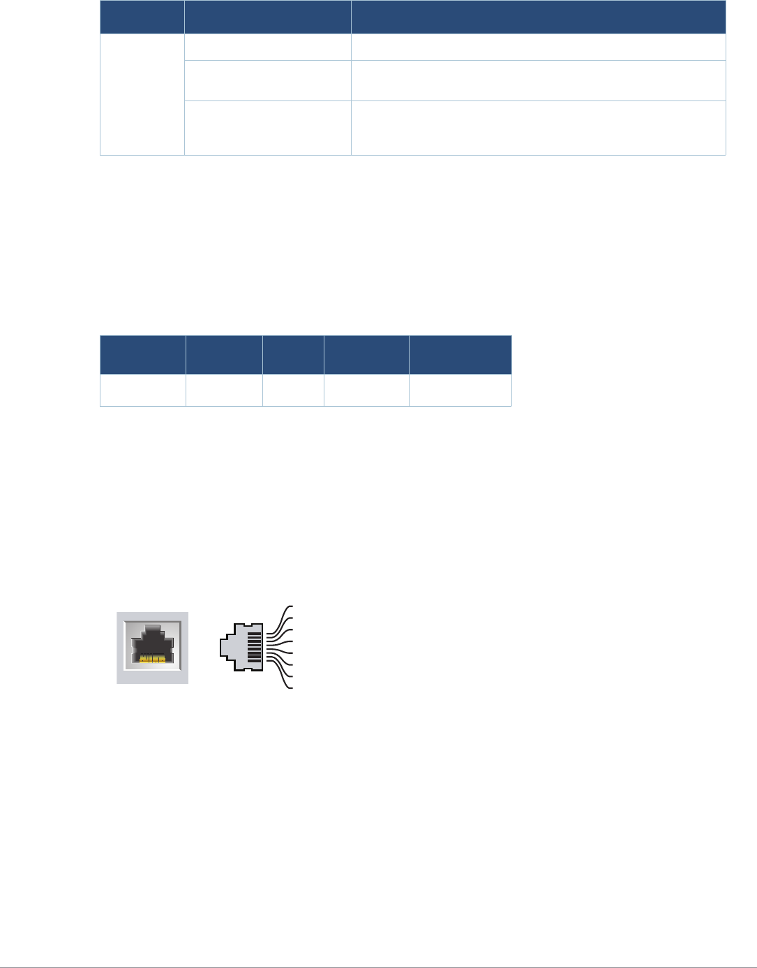
Grounding Point
Always remember to protect the AP by installing grounding lines. The ground connection must be
complete before connecting power to the AP enclosure.
Figure 4 AP-228 Rear View
Before You Begin
Pre-Installation Network Requirements
After WLAN planning is complete and the appropriate products and their placement have been
determined, the Aruba controller(s) must be installed and initial setup performed before the Aruba
APs are deployed.
!
CAUTION
FCC Statement: Improper termination of access points installed in the United States configured to non-US
model controllers will be in violation of the FCC grant of equipment authorization. Any such willful or
intentional violation may result in a requirement by the FCC for immediate termination of operation and may
be subject to forfeiture (47 CFR 1.80).
!
CAUTION
EU Statement:
Lower power radio LAN product operating in 2.4 GHz and 5 GHz bands. Please refer to the ArubaOS User Guide
for details on restrictions.
Produit réseau local radio basse puissance operant dans la bande fréquence 2.4 GHz et 5 GHz. Merci de vous
referrer au ArubaOS User Guide pour les details des restrictions.
Low Power FunkLAN Produkt, das im 2.4 GHz und im 5 GHz Band arbeitet. Weitere Informationen bezlüglich
Einschränkungen finden Sie im ArubaOS User Guide.
Apparati Radio LAN a bassa Potenza, operanti a 2.4 GHz e 5 GHz. Fare riferimento alla ArubaOS User Guide per
avere informazioni detagliate sulle restrizioni.
!
CAUTION
To meet regulatory restrictions, the access point must be professionally installed.
6AP-228 Wireless Access Point | Installation Guide
For initial setup of the controller, refer to the ArubaOS Quick Start Guide for the software version
installed on your controller.
Pre-Installation Checklist
Before installing your AP, be sure that you have the items listed below:
Gigabit Ethernet cable of required length
IEEE 802.3at compliant PoE source
Aruba Mobility Controller configured and installed on the network
Layer 2/3 network connectivity to your AP
One of the following network services:
Aruba Discovery Protocol (ADP)
DNS server with an “A” record
DHCP Server with vendor specific options
Verifying Pre-Installation Connectivity
Before you install APs in a network environment, make sure that the APs will be able to locate and
connect to the controller when they are powered on.
Specifically, you must verify the following conditions:
When connected to the network, each AP is assigned a valid IP address.
APs can locate the controller.
Refer to the ArubaOS Quick Start Guide for instructions on locating and connecting to the controller.
Identifying Specific Installation Locations
Use the AP placement map generated by Aruba’s RF Plan software application to determine the
proper installation location(s). Each location should be as close as possible to the center of the
intended coverage area and should be free from obstructions or obvious sources of interference.
These RF absorbers/reflectors/interference sources will impact RF propagation and should have been
accounted for during the planning phase and adjusted for in RF plan.
Identifying Known RF Absorbers/Reflectors/Interference Sources
Identifying known RF absorbers, reflectors, and interference sources while in the field during the
installation phase is critical. Make sure that these sources are taken into consideration when you
attach an AP to its fixed location. Examples of sources that degrade RF performance include:
Cement and brick
Objects that contain water
Aruba Networks, Inc. in compliance with governmental requirements, has designed the AP-228 such that only
authorized network administrators can change configuration settings. For more information about AP
configuration, refer to the ArubaOS Quick Start Guide and ArubaOS User Guide.
!
CAUTION
Access points are radio transmission devices and as such are subject to governmental regulation. Network
administrators responsible for the configuration and operation of access points must comply with local
broadcast regulations. Specifically, access points must use channel assignments appropriate to the location in
which the access point will be used.
AP-228 Wireless Access Point | Installation Guide 7
Metal
Microwave ovens
Wireless phones and headsets
Installing the AP
Using the AP-220-MNT-W1 Mount Kit
The AP-228 access point can be installed on a wall by using AP-220-MNT-W1 mount kit.
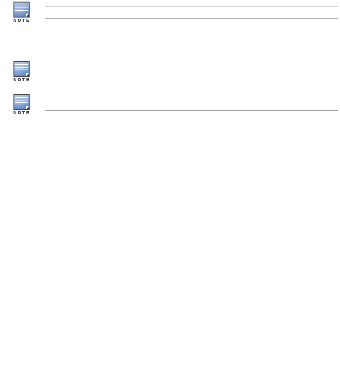
1. Begin by attaching the wall mount adapter to the wall.
a. Install any necessary wall anchors. Wall anchors are not included in this kit.
b. Align the screw holes in the mounting bracket with the previously installed anchors or
demarcated screw points.
c. Insert the screws to secure the mounting bracket. Screws are not included in this kit.
Service to all Aruba products should be performed by trained service personnel only.
The AP-228 access point does not ship with any mount kit. The AP-220-MNT-W1 mount kit is available as
accessories and must be ordered separately.
For details on AP-220-MNT-W1, please refer to the AP-220-MNT-W1 Installation Guide.
8AP-228 Wireless Access Point | Installation Guide
Figure 5 Attaching the Adapter to a Wall
Figure 6 Attaching the Adapter to a Wall (Alternate)
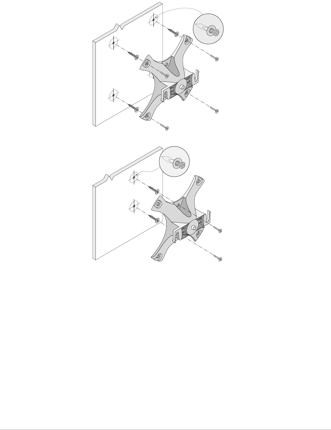
2. Attach necessary cables and/or antennas to the AP.
3. Attach the AP to the secured mounting adapter as shown in Figure 7.
a. Align the AP with a mounting adapter, placing the AP so that it’s mounting tabs are at an angle
of approximately 30 degrees to the adapter.
4. Pushing toward the wall, rotate the AP clockwise until it clicks into place (see Figure 7).
AP-220_11
AP-220_14
AP-228 Wireless Access Point | Installation Guide 9
Figure 7 Attaching the AP to the Mounting Bracket
Figure 8 Completed Installation
Grounding the AP
The grounding must be completed before powering up the AP. The grounding wire should be #8
AWG.
1. Peel the cover of one end of the grounding wire and place the bare grounding wire into the
included copper lug, and press firmly with the crimping pliers.
2. Fasten the copper lug to the grounding hole on the AP with the included M4 x6 screw.
Connecting the Ethernet Cable
To connect the Ethernet cable to the AP, perform the following steps using the cable glands that ships
with your AP.
WARNING
Failure to use the included Ethernet cable glands can lead to connectivity and POE issues.
10 AP-228 Wireless Access Point | Installation Guide
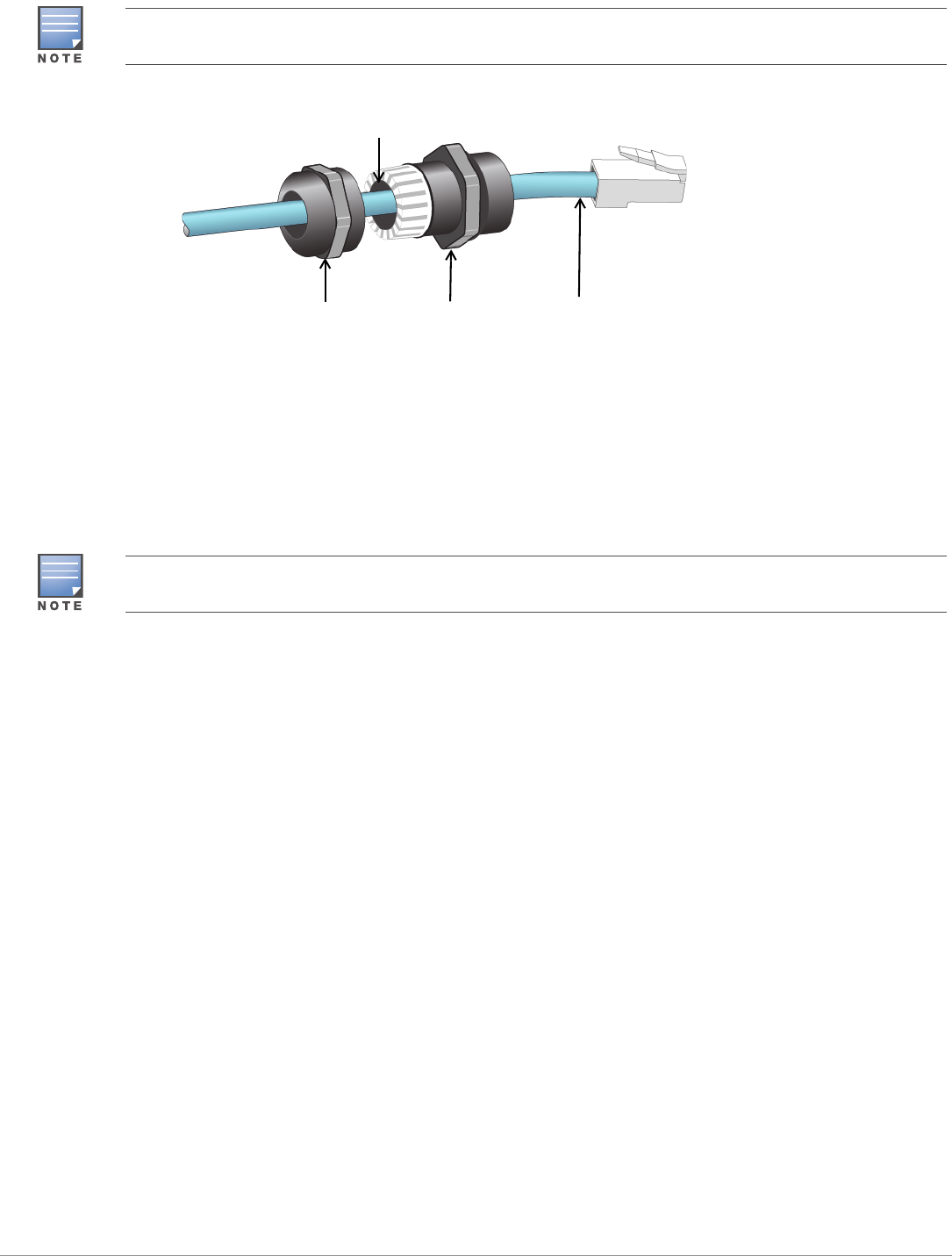
Figure 9 Installing a Cable Gland
1. Slide the sealing nut over the cable (without the RJ45 connector attached to the end).
2. Slide the clamping ring over the cable.
3. Using a crimping tool, attach the shielded RJ45 connector to the end of the cable.
4. Remove the weatherproof cap on the Ethernet port.
5. Insert the RJ45 connector to the Ethernet port.
6. Screw the clamping ring onto the Ethernet port.
7. Screw the sealing nut onto the clamping ring.
Verifying Post-Installation Connectivity
The integrated LEDs on the AP can be used to verify that the AP is receiving power and initializing
successfully (see Table 1 and Table 2). Refer to the ArubaOS Quick Start Guide for further details on
verifying post-installation network connectivity.
Configuring the AP
AP Provisioning/Reprovisioning
Provisioning parameters are unique to each AP. These local AP parameters are initially configured on
the controller which are then pushed out to the AP and stored on the AP itself. Aruba recommends
that provisioning settings be configured via the ArubaOS Web UI only. Refer to the ArubaOS User
Guide for complete details.
AP Configuration
Configuration parameters are network or controller specific and are configured and stored on the
controller. Network configuration settings are pushed out to the AP(s) but remain stored on the
controller.
Configuration settings can be configured via the ArubaOS Web UI or ArubaOS CLI. Refer to the
ArubaOS User Guide for complete details.
The cable is not included and must be purchased separately. Purchase a suitable UV-resistant, outdoor rated,
CAT 5E or better RJ45 cable for use with the AP.
Sealing Nut Clamping Ring CAT 5E or Better Cable
Seals
The seals inside the clamping ring by factory default is applicable for cables with 5-8.5 mm diameter. In the
cable gland kit, another seals is provided for use with the cables with 7-10 mm diameter.

AP-228 Wireless Access Point | Installation Guide 11
Product Specifications
Mechanical:
Device Dimensions (HxWxD): 8.7 inches x 5.9 inches x 2.6 inches (221mm x 150mm x 66mm)
Electrical
Ethernet
2 x 10/100/1000Base-T auto-sensing Ethernet RJ-45 Interfaces
MDI/MDX
Power over Ethernet (IEEE 802.3at compliant), 48VDC(nominal) /0.6A
Power
POE support on WAN port: 802.3at-compliant POE sourcing devices
Environmental
Operating
Temperature: -40ºC to 60ºC (-40ºF to 140ºF)
Humidity: 5% to 95% non-condensing
Storage
Temperature: -40ºC to 85ºC (-40ºF to 185ºF)
For additional specifications on this product, please refer to the data sheet. The data sheet can be
found at www.arubanetworks.com.
12 AP-228 Wireless Access Point | Installation Guide
Safety and Regulatory Compliance
Aruba Networks provides a multi-language document that contains country-specific restrictions and
additional safety and regulatory information for all Aruba access points. This document can be
viewed or downloaded from the following location: www.arubanetworks.com/safety_addendum
Regulatory Model Name
The regulatory model name of AP-228 is APIN0228.
FCC
This device is electronically labeled. To view the FCC ID:
1. Log into the controller WebUI
2. Navigate to Maintenance > Controller > About.
FCC Class B Part 15
This device complies with Part 15 of the Federal Communications Commission (FCC) Rules. Operation
is subject to the following two conditions:
This device may not cause harmful interference.
This device must accept any interference received, including interference that may cause
undesired operation.
This equipment has been tested and found to comply with the limits for a Class B digital device,
pursuant to Part 15 of the FCC Rules. This equipment generates, uses and can radiate radio
frequency energy and, if not installed and used in accordance with the manufacturer’s instructions,
may cause interference harmful to radio communications.
If this equipment does cause interference, which can be determined by turning the equipment off
and on, the user is encouraged to try to correct the interference by one or more of the following
measures:
Reorient or relocate the receiving antenna.
Increase the separation between the equipment and receiver.
Connect the equipment to an outlet on a circuit different from that to which the receiver is
connected.
Consult the dealer or an experienced radio or TV technician for help.
!
CAUTION
Aruba access points must be installed by a professional installer. The professional installer is responsible for
ensuring that grounding is available and it meets applicable local and national electrical codes.
!
CAUTION
RF Radiation Exposure Statement: This equipment complies with FCC RF radiation exposure limits. This
equipment should be installed and operated with a minimum distance of 9.84 inches (25 cm) between the
radiator and your body for 2.4 GHz and 5 GHz operations. This transmitter must not be co-located or operating
in conjunction with any other antenna or transmitter.
!
CAUTION
Changes or modifications to this unit not expressly approved by the party responsible for compliance could
void the user’s authority to operate this equipment.
AP-228 Wireless Access Point | Installation Guide 13
EU Regulatory Conformance
Aruba Networks, Inc., hereby declares that the APIN0228 device model is in compliance
with the essential requirements and other relevant provisions of Directive 1999/5/EC -CE(!). The
Declaration of Conformity made under Directive 1999/5/EC is available for viewing at
www.arubanetworks.com.
Proper Disposal of Aruba Equipment
For the most current information about Global Environmental Compliance and Aruba products, see
our website at www.arubanetworks.com.
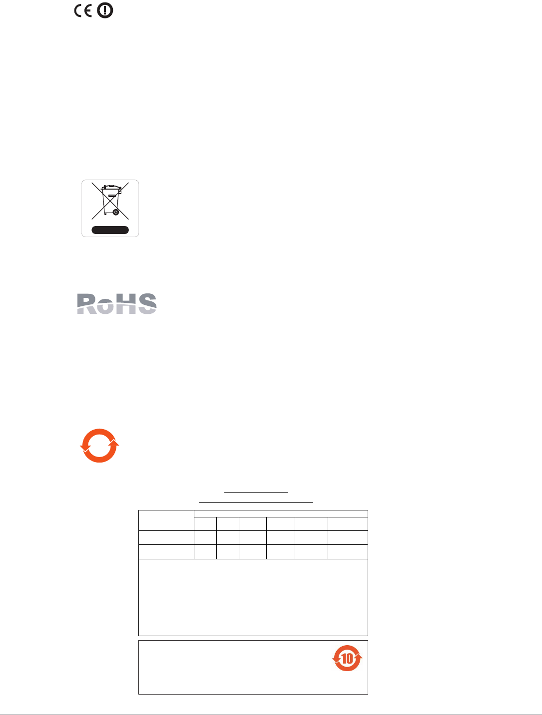
Waste of Electrical and Electronic Equipment
Aruba products at end of life are subject to separate collection and treatment in the
EU Member States, Norway, and Switzerland and therefore are marked with the
symbol shown at the left (crossed-out wheelie bin). The treatment applied at end of
life of these products in these countries shall comply with the applicable national
laws of countries implementing Directive 2002/96EC on Waste of Electrical and
Electronic Equipment (WEEE).
European Union RoHS
Aruba products also comply with the EU Restriction of Hazardous Substances
Directive 2011/65/EC (RoHS). EU RoHS restricts the use of specific hazardous
materials in the manufacture of electrical and electronic equipment. Specifically,
restricted materials under the RoHS Directive are Lead (including Solder used in printed circuit
assemblies), Cadmium, Mercury, Hexavalent Chromium, and Bromine. Some Aruba products are
subject to the exemptions listed in RoHS Directive Annex 7 (Lead in solder used in printed circuit
assemblies). Products and packaging will be marked with the “RoHS” label shown at the left indicating
conformance to this Directive.
China RoHS
Aruba products also comply with China environmental declaration requirements and
are labeled with the “EFUP 10” label shown at the left.
10
᳝↦᳝ᆇ⠽䋼ໄᯢ
Hazardous Materials Declaration
᳝↦᳝ᆇ⠽䋼ܗ㋴(Hazardous Substance)
䚼ӊৡ⿄
(Parts) 䪙
3E
∲
+J
䬝
&G
݁Ӌ䫀
&U
⒈㘨㣃
3%%
⒈Ѡ㣃䝮
3%'(
⬉䏃ᵓ
(PCA Boards) hƻƻ ƻ ƻ ƻ
ᴎẄ㒘ӊ
(Mechanical Sub-Assemblies)
hƻƻ ƻ ƻ ƻ
ƻ˖ 㸼⼎䆹᳝↦᳝ᆇ⠽䋼䆹䚼ӊ᠔᳝ഛ䋼ᴤ᭭Ёⱘ䞣ഛ SJ/T11363-2006 ᷛޚ㾘ᅮⱘ䰤䞣㽕∖ҹϟDŽ
Indicates that the concentration of the hazardous substance in all homogeneous materials in the parts is
below the relevant threshold of the SJ/T11363-2006 standard.
h˖ 㸼⼎䆹᳝↦᳝ᆇ⠽䋼㟇ᇥ䆹䚼ӊⱘᶤϔഛ䋼ᴤ᭭Ёⱘ䞣䍙ߎ6-7ᷛޚ㾘ᅮⱘ䰤䞣㽕∖DŽ
Indicates that the concentration of the hazardous substance of at least one of all homogeneous materials
in the parts is above the relevant threshold of the SJ/T11363-2006 standard.
ᇍ䫔ଂП᮹ⱘ᠔ଂѻકᴀ㸼ᰒ⼎կᑨ䫒ⱘ⬉ᄤֵᙃѻકৃ㛑ࣙ䖭ѯ⠽䋼DŽ
This table shows where these substances may be found in the supply chain of electronic information
products, as of the date of sale of the enclosed product.
ℸᷛᖫЎ䩜ᇍ᠔⍝ঞѻકⱘ⦃ֱՓ⫼ᳳᷛᖫᶤѯ䳊䚼ӊӮ᳝ϔϾϡৠⱘ⦃ֱՓ⫼ᳳ
՟བ⬉∴ऩܗഫ䌈݊ѻકϞ
ℸ⦃ֱՓ⫼ᳳ䰤া䗖⫼ѢѻકᰃѻકݠЁ᠔㾘ᅮⱘᴵӊϟᎹ
The Environment- Friendly Use Period (EFUP) for all enclosed products and their parts are
per the symbol shown here. The Environment- Friendly Use Period is valid only when the
product is operated under the conditions defined in the product manual.

14 AP-228 Wireless Access Point | Installation Guide
Canadian Statement
Under Industry Canada regulations, this radio transmitter may only operate using an antenna of a
type and maximum (or lesser) gain approved for the transmitter by Industry Canada. To reduce
potential radio interference to other users, the antenna type and its gain should be so chosen that
the equivalent isotropically radiated power (e.i.r.p.) is not more than that necessary for successful
communication.
This device complies with Industry Canada licence-exempt RSS standard(s).
Operation is subject to the following two conditions: (1) this device may not cause interference, and
(2) this device must accept any interference, including interference that may cause undesired
operation of the device.
The device for operation in the band 5150-5250 MHz is only for indoor use to reduce the potential for
harmful interference to co-channel mobile satellite systems;
The maximum antenna gain permitted for devices in the bands 5250-5350 MHz and 5470-5725 MHz
shall comply with the e.i.r.p. limit; and the maximum antenna gain permitted for devices in the band
5725-5825 MHz shall comply with the e.i.r.p. limits specified for point-to-point and non point-to-point
operation as appropriate.
Users should also be advised that high-power radars are allocated as primary users (i.e. priority
users) of the bands 5250-5350 MHz and 5650-5850 MHz and that these radars could cause
interference and/or damage to LE-LAN devices.

AP-228 Wireless Access Point | Installation Guide 15
This page is intentionally left blank.
© 2015 Aruba Networks, Inc. All rights reserved.
www.arubanetworks.com
1344 Crossman Avenue
Sunnyvale, California 94089
Phone: 408.227.4500
Fax 408.227.4550
16 AP-228 Wireless Access Point | Installation Guide
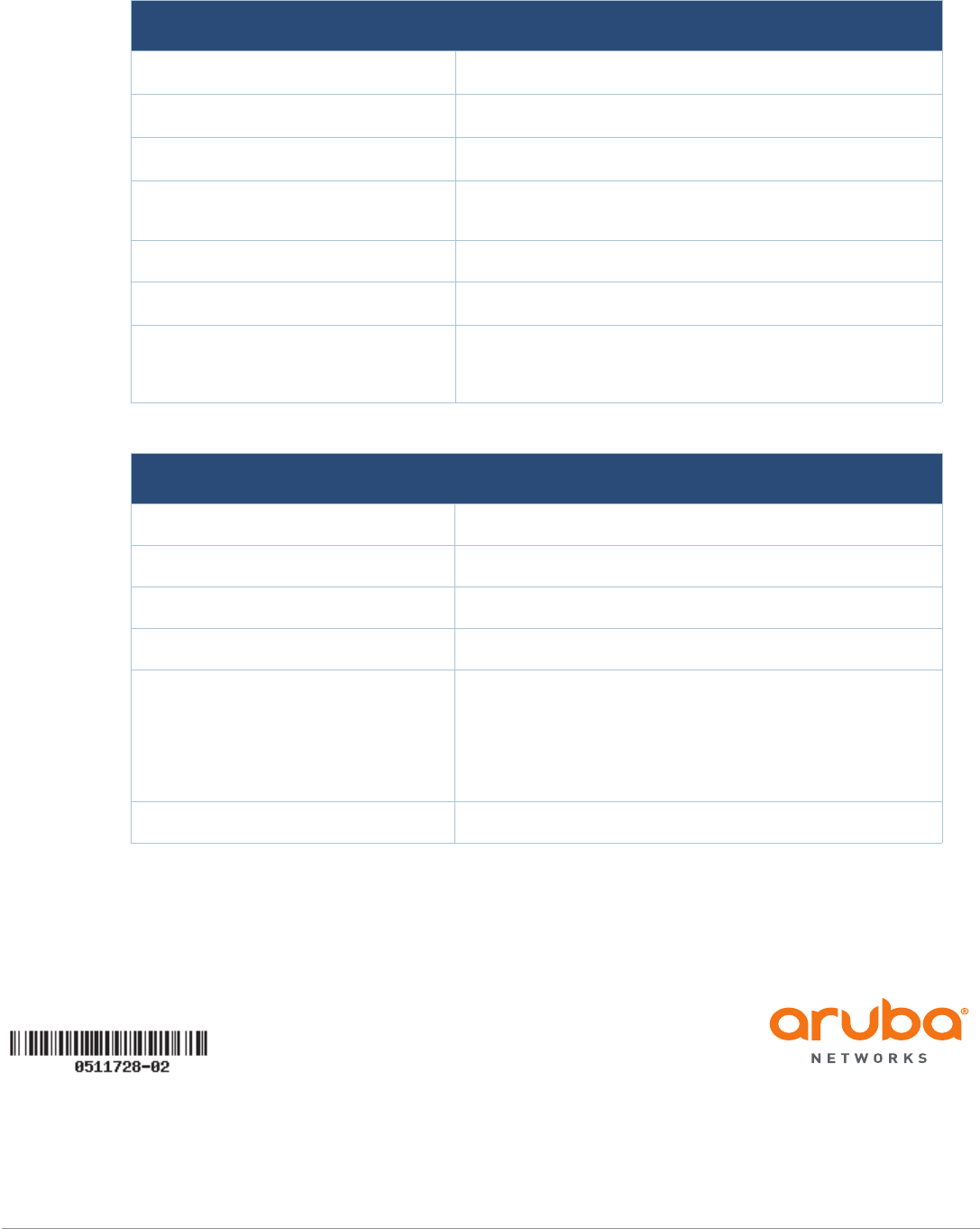
Contacting Aruba Networks
Web Site Support
Main Site http://www.arubanetworks.com
Support Site https://support.arubanetworks.com
Software Licensing Site https://licensing.arubanetworks.com/login.php
Wireless Security Incident
Response Team (WSIRT) http://www.arubanetworks.com/support/wsirt.php
Support Emails
Americas, APAC and EMEA support@arubanetworks.com
WSIRT Email
Please email details of any security
problem found in an Aruba product.
sirt@arubanetworks.com
Telephone Support
Aruba Corporate +1 (408) 227-4500
FAX +1 (408) 227-4550
Support
United States 800-WI-FI-LAN (800-943-4526)
Universal Free Phone Service
Number (UIFN): Australia, Canada,
China, France, Germany, Hong Kong,
Ireland, Israel, Japan, Korea,
Singapore, South Africa, Taiwan, and
the UK.
+800-4WIFI-LAN (+800-49434-526)
All Other Countries +1 (408) 754-1200