Asiatelco Technologies ALM-N245 LTE Mobile hotspot User Manual KTHY NF210
Asiatelco Technologies Co. LTE Mobile hotspot KTHY NF210
Contents
- 1. ALM-N245 Instructions v1_1-20150626
- 2. ALM-N245 Instructions v1.1-20150626
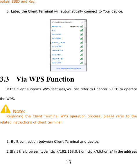
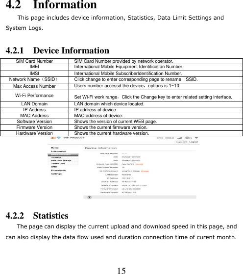
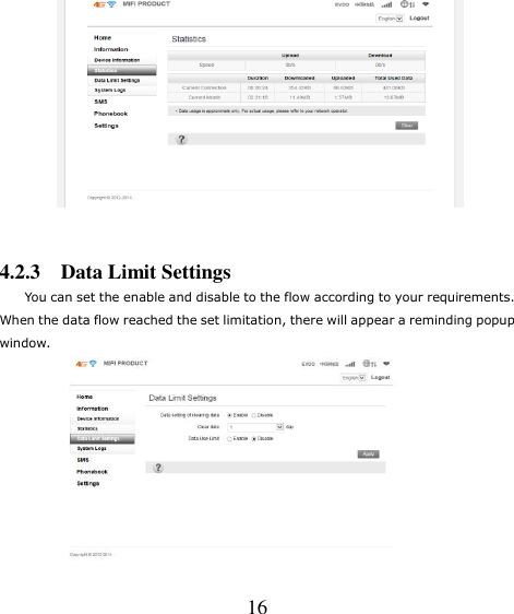
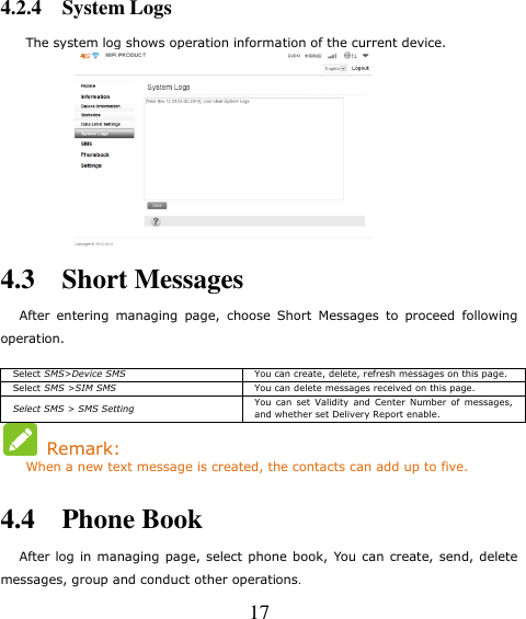
ALM-N245 Instructions v1_1-20150626


ALM-N245 Instructions v1.1-20150626