Asiatelco Technologies ALM-N245 LTE Mobile hotspot User Manual KTHY NF210
Asiatelco Technologies Co. LTE Mobile hotspot KTHY NF210
Contents
- 1. ALM-N245 Instructions v1_1-20150626
- 2. ALM-N245 Instructions v1.1-20150626
ALM-N245 Instructions v1_1-20150626

ALM-N245 4G MiFi
User Manual
v1.0

content
Chapter 1 Introduction ................................. 1
1.1 Introduction ........................................ 1
1.2 Appearances and Parts ......................... 1
1.3 LCD Display ...................................... 2
1.4 Packing Lists ...................................... 3
1.5 Application Scene ............................... 3
1.6 Sleep Mode ........................................ 4
Chapter 2 Installation Instruction ................. 4
2.1 Install SIM Card and Battery ................ 4
2.2 Power on/off Your Device .................... 6
2.3 Charging ............................................ 6
Chapter 3 Connect to Your Device .............. 7
3.1 Via USB ............................................ 7
3.2 Via Wi-Fi ........................................... 9
3.3 Via WPS Function ............................ 13
Chapter 4 WebUI Managing Page ............. 14

4.1 managing page .................................. 14
4.2 Information ...................................... 15
4.2.1 Device Information ...................... 15
4.2.2 Statistics ................................... 15
4.2.3 Data Limit Settings ...................... 16
4.2.4 System Logs .............................. 17
4.3 Short Messages ................................. 17
4.4 Phone Book ...................................... 17
4.5 Settings ............................................ 18
4.5.1 Quick Settings ............................ 18
4.5.2 Network Settings ......................... 19
4.5.3 WIFI Setting .............................. 22
4.5.4 Device settings ........................... 25
4.5.5 Firewall .................................... 31
4.5.6 Router Settings ........................... 33
4.5.7 Update ..................................... 33
Chapter 5 LCD display ............................... 34
5.1 1th main screen .............................. 34
5.2 2nd WiFi ....................................... 35

5.3 3rd Data flow and Battery volume .... 35
5.4 4th SMS ........................................... 35
5.5 5th WPS ........................................ 36
5.6 6th Reset Factory Settings .................. 36
Chapter 6 Safety Instruction ....................... 37
Chapter 7 Q&A .......................................... 40

1
Chapter 1 Introduction
1.1 Introduction
ALM-N245 is one of the MiFi products that supports CDMA /TD-LTE/LTE FDD
network. The Client Terminal can be connected to ALM-N245 via Wi-Fi or USB,
enabling you to enjoy the fun of high speed internet surfing anytime anywhere.
This User Manual introduces how to install and use this device. For more
information about network connection service, please consult Your network
operator.
Note:
Long time working of this device can cause sectional environmental
temperature rising and heat generation, in that case, the device may automatically
power off to realize self safety preservation. Therefore, do not place the device in a
closed environment or environment with small cooling space. When this situation
happens, please place the device in a ventilating space to cool it adequately, and
then start the device normally.
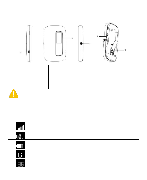
1.2 Appearances and Parts
The appearances and parts of this product are shown in the following picture.
This picture is for reference only, please prevail in kind.

2
1. Charger/USB
Interface
Charger interface;
USB interface between device and Client Terminal.
2. LCD Display
To instruct device conditions.
3. Power Button
Press Power Buton to power on/off the device.
Awake the device when it is in Steep Mode.
Double click power key quickly to switch screen.
4. Reset
Hardware restore factory settings,long press 3 seconds.
5. SIM Card Slot
Used to insert the SIM card.
Note:
When the device is turned on,the LCD screen will be closed after 1 minute.
1.3 LCD Display
Indicator
Description
Indicates network signal.
Number of users connected through WLAN.
Indicates battery capacity.
Connect to CDMA-1X network.
Connect to CDMA 2000 network.
3
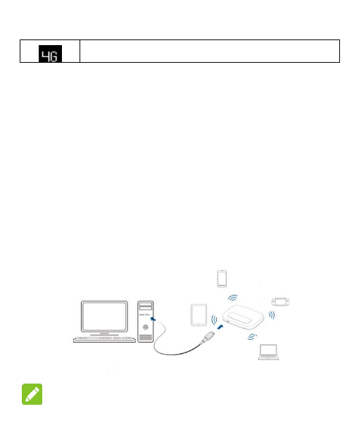
Connect to TD-LTE/LTE FDD 4G network.
1.4 Packing Lists
A host
A USB cable
A guarantee card
A certificate
1.5 Application Scene
This device support multiple Client Terminals share the internet via Wi-Fi or USB.
The following picture is for reference.
Remark:

4
1.Connect the Client Terminal to this device via Wi-Fi or USB.
2.Before connecting via Wi-Fi, make sure the Client Terminal supports Wi-Fi
function.
1.6 Sleep Mode
When the WLAN function is turned on and the device is powered only by battery,
if no Client Terminals are connected to the device within 10 minutes, the device will
enter into Sleep Mode, and the LCD display will be off. In Sleep Mode, WLAN
function will be turned off, awake the device by pressing Power button, and then the
LCD display will be on.
Chapter 2 Installation
Instruction
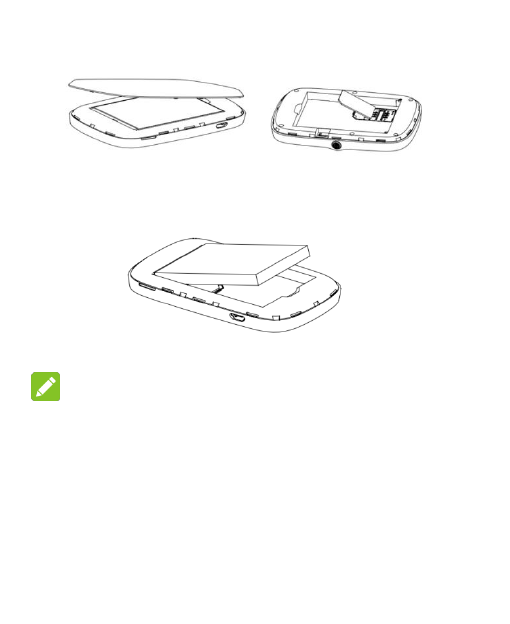
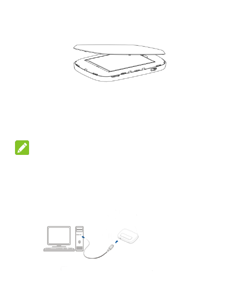
2.1 Install SIM Card and Battery
1.Lift up the back cover as shown in the following picture, remove the back
cover after it detaches from the clip.As shown in the following picture, insert the
SIM card into SIM card slot.
5
2. As shown in the following picture, place the battery into battery slot.
Remark
Please insert the metal contact end of the battery first.
3. Align the back cover with the clip, place the back cover on the device, and close
the back cover as shown in the following picture.

6
2.2 Power on/off Your Device
Press the Power button to turn on/off Your device.
Remark:
When the LCD display is on, Your device has already been powered on.
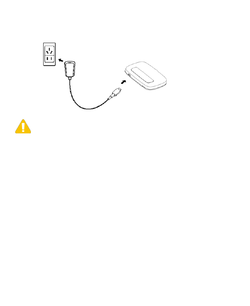
2.3 Charging
1. Connect Your device to the computer via USB line directly.
7
2. Connect the device to AC power socket via charger and USB line.
Note:
The plug of USB line can only be inserted into Your device in particular direction,
please do not insert and pull it in an inappropriate way.
Chapter 3 Connect to Your
Device
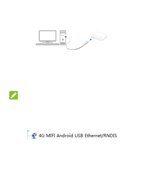
3.1 Via USB
1. Use a USB line to connect Your device to the Client Terminal.

8
2.Turn on Your device.
3.Choose an installing language.
4. Complete installation according to system prompts . (Skip this step for
drive-free version)
Remark:
1.If the system does not support automatic installation, please run
DriverSetup.exe program in My Computer> CD-ROM drive to start software
installation.
2.After the software is installed successfully, the device driver will be installed
successfully at the same time. Meanwhile in the Device Manager shows:
5. After installation, in Start> Program menu will show kfi-driver Client Terminal
Program Group, meanwhile there will be a Shortcut icon on the desk (if Create a
shortcut is clicked during installation). Later, connection between Client Terminal
and the device will be created successfully.

9
3.2 Via Wi-Fi
1.Turn on the device, wait for 1~2 minutes till the device initialization is
completed.
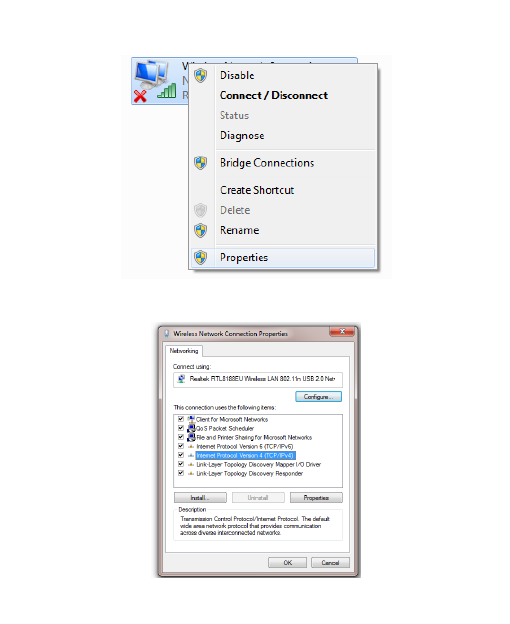
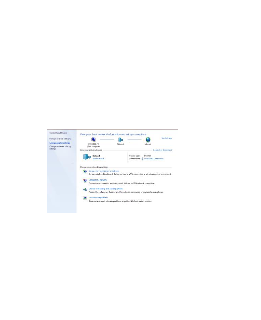
2. Before connecting via Wi-Fi, please configure the computer. Take Windows 7
as an instance, configure Wi-Fi connection Internet Protocol.
A)Click Start->Control Panel->Network and Internet->Network and Sharing
Center, choose Change Adapter Settings.
B)Right-click on Local Connection, choose Property.
10
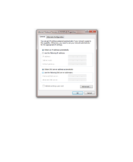
C)Click Internet Protocol (TCP/IP), choose Property.

11
D)Select Obtain an IP Address Automatically and Obtain DNS Server Address
Automatically, click Confirm to complete configuration.
3.Select the corresponding SSID of the device, click Connect.
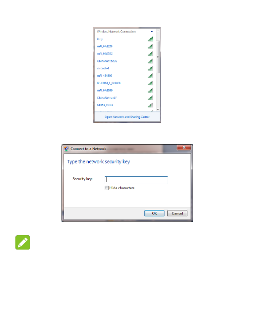
12
4. Enter the Key and click Connect.
Remark:
In order to prevent the device from being used illegally, there may appear a
prompt during installation and demanding the Key. Please refer to the device label
to obtain the default SSID and Key info, or double-click WPS function button to
13
obtain SSID and Key.
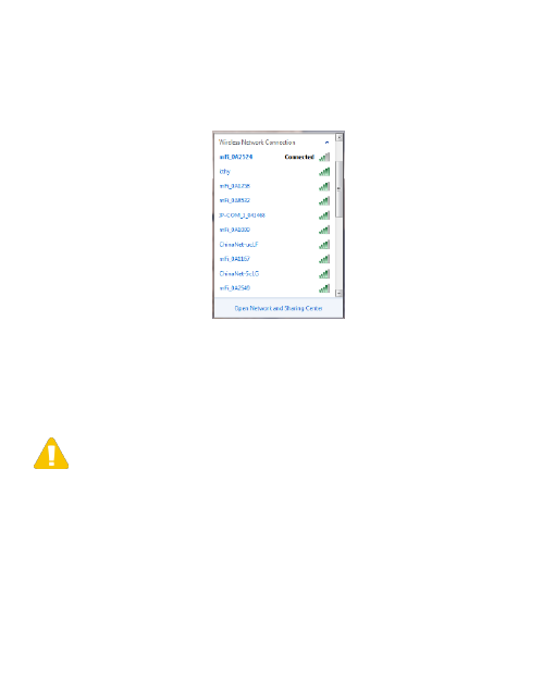
5. Later, the Client Terminal will automatically connect to Your device,
3.3 Via WPS Function
If the client supports WPS features,you can refer to Chapter 5 LCD to operate
the WPS.
Note:
Regarding the Client Terminal WPS operation process, please refer to the
related instructions of client terminal.
1. Built connection between Client Terminal and device.
2.Start the browser, type http://192.168.0.1 or http://kfi.home/ in the address
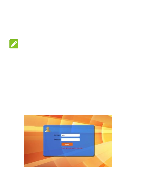
14
bar to enter managing page.
Remark:
Advise to use the following browsers: IE (7.0 or higher), Firefox (3.0 or higher),
Opera (10.0 or higher), Safari (4.0 or higher) or Chrome (5.0 or higher).
Chapter 4 WebUI Managing
Page
4.1 managing page
The Login interface of managing page is shown as follows.
15
4.2 Information
This page includes device information, Statistics, Data Limit Settings and
System Logs.
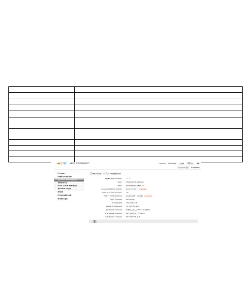
4.2.1 Device Information
SIM Card Number
SIM Card Number provided by network operator.
IMEI
International Mobile Equipment Identification Number.
IMSI
International Mobile SubscriberIdentification Number.
Network Name(SSID)
Click change to enter corresponding page to rename SSID.
Max Access Number
Users number accessd the device,options is 1~10.
Wi-Fi Performance
Set Wi-Fi work range,Click the Change key to enter related setting interface.
LAN Domain
LAN domain which device located.
IP Address
IP address of device.
MAC Address
MAC address of device.
Software Version
Shows the version of current WEB page.
Firmware Version
Shows the current firmware version.
Hardware Version
Shows the current hardware version.
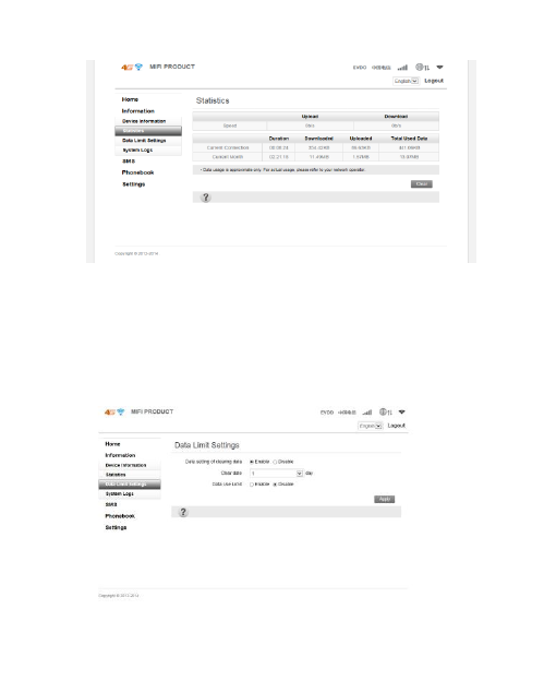
4.2.2 Statistics
The page can display the current upload and download speed in this page, and
can also display the data flow used and duration connection time of curent month.
16
4.2.3 Data Limit Settings
You can set the enable and disable to the flow according to your requirements.
When the data flow reached the set limitation, there will appear a reminding popup
window.
17
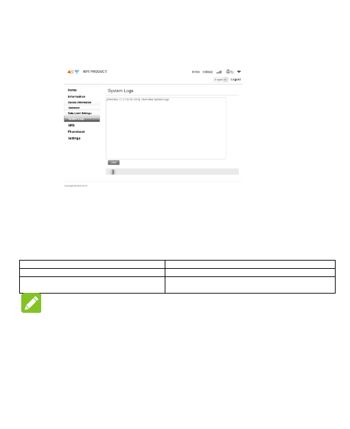
4.2.4 System Logs
The system log shows operation information of the current device.
4.3 Short Messages
After entering managing page, choose Short Messages to proceed following
operation.
Select SMS>Device SMS
You can create, delete, refresh messages on this page.
Select SMS >SIM SMS
You can delete messages received on this page.
Select SMS > SMS Setting
You can set Validity and Center Number of messages,
and whether set Delivery Report enable.
Remark:
When a new text message is created, the contacts can add up to five.
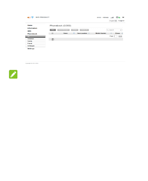
4.4 Phone Book
After log in managing page, select phone book, You can create, send, delete
messages, group and conduct other operations.

18
Remark:
Please note the capacity of contacts in the phonebook。
4.5 Settings
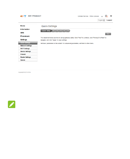
4.5.1 Quick Settings
After log in the managing page, select Quick Settings.

19
Quick Settings will instruct you how to configure Your device in a safe method,
please operate according to the page prompts. After correct configuration is
completed, You will be enabled to use the internet service.
Remark:
All the parameters may be set by default; in that case, you can use the
Internet directly. If you need to change the parameters, please consult your
network operator.
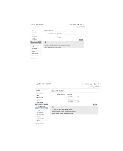
4.5.2 Network Settings
In the Network settings page,you can operate dial settings, network settings,
APN configuration.

20
1.Dial settings
In this page,two wan connection modes are optional:auto and manual.
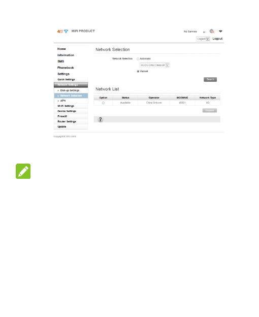
2. Network Selection
Two kinds of Network Selection: auto and manual.
Auto:There are four network selections in this mode,which are 4G/3G/2G、
4G/3G、3G/2G、4G etc., user can choose favorable network mode according to
specific circumstances of network.
Manual:select manual>search,entering the status of search network. After
searching,there will show a network list that the device can register,as shown in the
following:

21
Select network available> register,After registering,network will be
connected automatically again.
Remark:
When manual is selected,you should disconnect network on the home page or
operate according to tips.
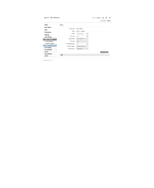
3.APN settings
In auto mode,the APN information will be configured automatically on the
basis of SIM card inserted.
Generally,APN is configured automatically,if auto configure don't success,
select manual please. For detail configuration information, please refer to your
network operator.
22
The following is the way to set APN manually.
1)Disconnect data service manually,select manual> add on the APN page.
2)Input the profile name and IPV4 APN of APN added manually,then click
Apply.
3)Back to APN page>manual ,select profile added ,then click set as default.
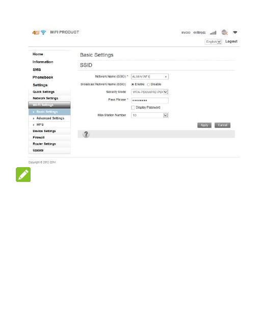
4.5.3 WIFI Setting
1. Basic setting
Wi-Fi basic setting includes: network name (SSID), safe mode, pass word
selection and setting.

23
Remark:
For the network safe,please modify password timely.
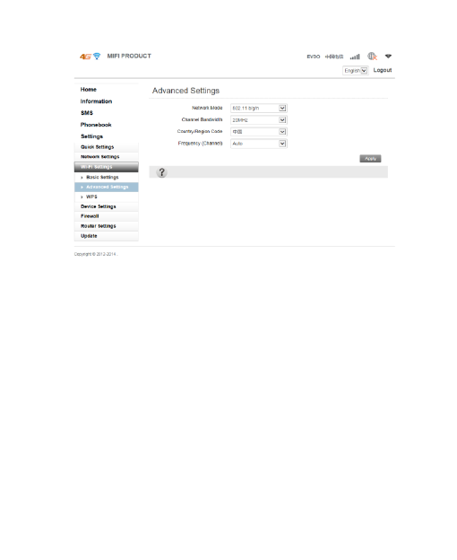
2.Advance Setting
Including network mode、Channel Bandwidth、Country/Region Code、
Frequency (Channel).

24
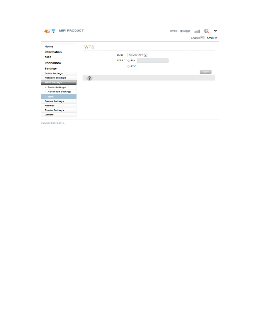
3.WPS Settings
You can enable Wi-Fi Protected Setup(WPS) by PIN(PIN code) or
PBC(push-button) mode on this page.
PIN: Enter PIN that is generated by wireless access client.
PBC: Select PBC or press PBC button on the device.
25
4.5.4 Device settings
Device settings includes Account Management,PIN Management,Reset Factory
Settings,Restart,Power save,Date Management.
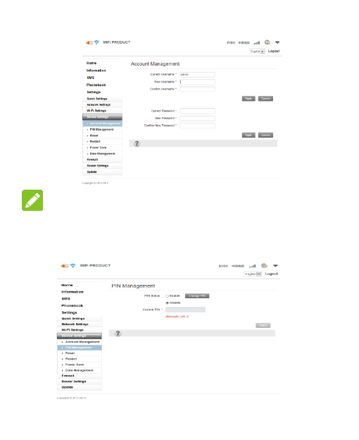
1. Account Management
Account management is used to set WenUI login username and password for
administrator,both of the initial value are admin.
26
Remark:
For protecting network,please modify login username and password of WebUI.
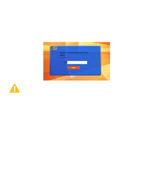
2. PIN Management
Select settings>device settings > pin management to modify pin status.

27
When pin validate service is enabled,it is necessary to input pin code while
entering login page first time.
Note:
SIM card will be locked if you input pin code three times incorrectly. For this
case, please refer to your network operator.
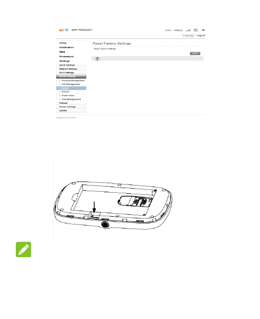
3.Reset to Factory Default
There are two ways to reset to factory default:
a). In software,select settings>device settings>reset.

28
b). In hardware,press the position shown by the arrow for 3 seconds to restore
to factory default.
Remark:
If forget the WebUI login password,you can reset factory default by the
hardware way,and login WebUI according to initial username and password.
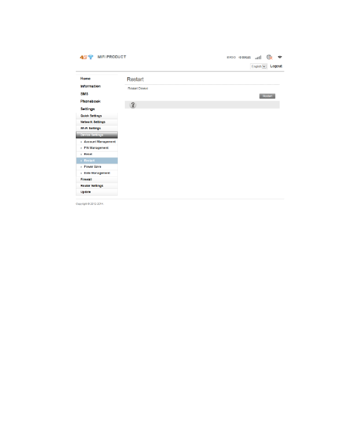
4.Restart
29
In restart page, you can click on the restart button to restart the device.
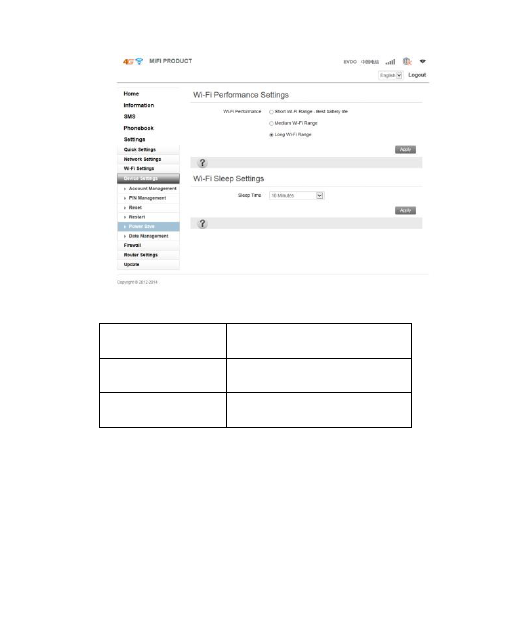
5. Power save
Because Wi-Fi coverage directly affect the device power consumption, please
select the appropriate Wi-Fi performance settings and the sleep time。

30
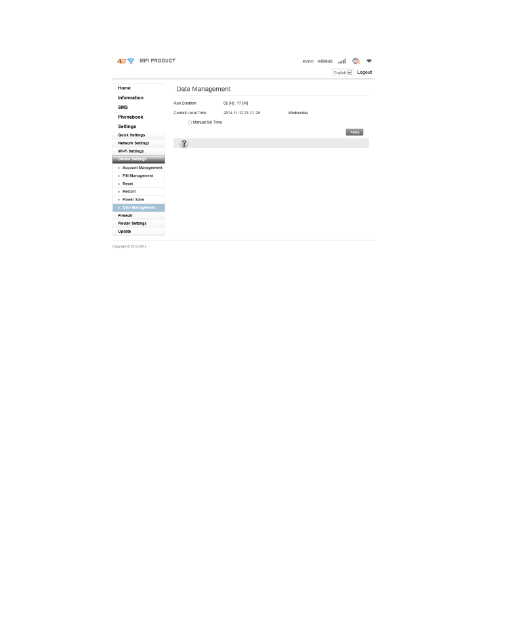
6.Date Management.
Run Duration
Shows the time device is turned on.
Current Local Time
Shows the current time of device.
Manual Set Time
Set the local time manually, take effect
after application.

31
4.5.5 Firewall
You can set firewall policies to protect your network from viruses, worms and
malicious activities on the Internet, to make the device running on a secure
network.
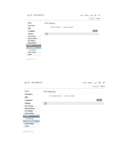
1. Port Filtering
when port filtering is enabled, you can set MAC/IP/Port Filtering by yourself,
default setting is disabled.

32
2. Port Mapping
Configure a Port Mapping to enable external computers to access WWW, FTP
or other services provided by LAN.
33
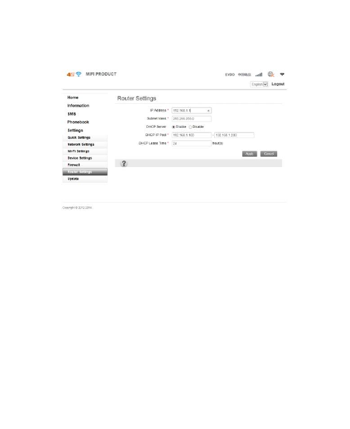
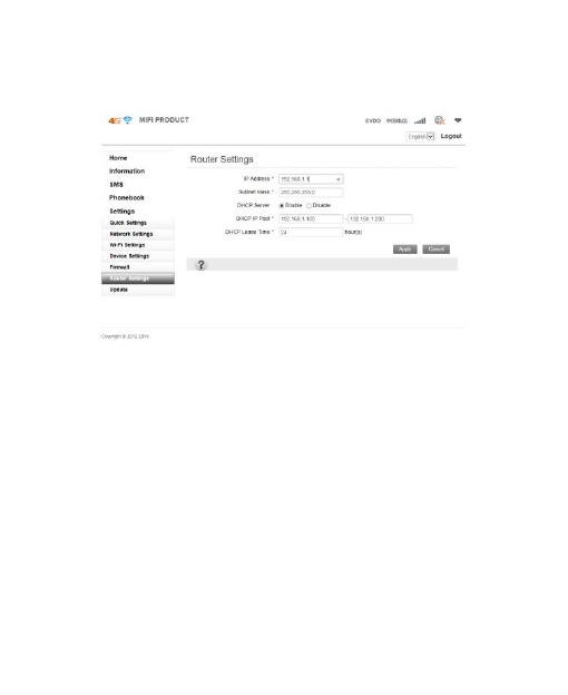
4.5.6 Router Settings
You can set IP address, subnet mask,DHCP in this page.
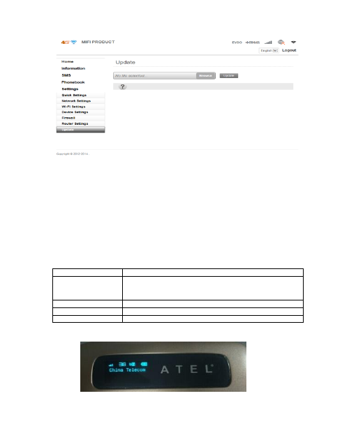
4.5.7 Update
Please download the latest installation package corresponding to device models
on the website. Click Browse, select the upgrade program you have downloaded at
local client, click on the upgrade, the system will automatically upgrade the device
to optimize the use of the product.
34
Chapter 5 LCD display
LCD has main screen and five sub screen,on the power on status,you can
double click power key quickly to switch each screen.
5.1 1th main screen
Display four status icon and network operator.
Signal strength
Using signal bar to display signal strength.
Network mode
LTE 4G
EVDO 3G
CDMA1× 1×
WiFi
Using wifi icon to express whether wifi is enabled or not.
Battery capacity
Using battery icon to express current battery capacity.
Main body
Display the name of current network operator.

35
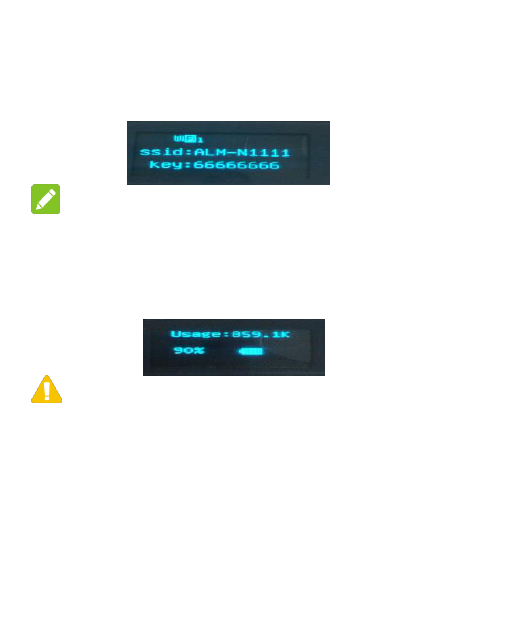
5.2 2nd WiFi
After entering this screen,it will diaplay SSID、KEY and the numbers of WiFi
accessed.
Remark:
While ssid and key is modified, lcd will update both of them synchronously.
5.3 3rd Data flow and Battery volume
After entering this screen,it will diaplay the cumulative use of data flow and
battery volume.
note:
Date setting of clearing data is enabled in default. System will clear data flow of
last month to zero automatically at t 1th day of every month ,and start to count
current data flow again.
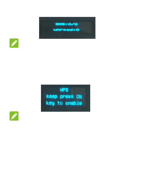
5.4 4th SMS
This screen display sms information.
SMS:0/0:current sms numbers /sms capacity
Unread: sms unreaded

36
Remark:
LCD only display current sms numbers、sms capacity and sms unreaded,the
content of sms received can only read on the WebUI.
5.5 5th WPS
In this screen, you can long press power key can make LCD flicker and open wps .
Remark:
In this screen, long press power key can not let device power off,but to light the
LED green and open wps .
5.6 6th Reset Factory Settings
After entering this screen, you can long press power key to reset all settings to
defaults.

37
Chapter 6 Safety Instruction
Personal Use
● Using this device and other RF equipment may cause interference to some
equipment that has a bad performance for shielding, such as some electronic
system in motor vehicle. When necessary, please consult the device manufacturer
before using this device.
● When use this device near some medical device such as audiphones, cochlear
implants and pacemaker, please keep at least 20 cm distance between this device
and the medical devices; when necessary please power off this device. In You have
other questions, please consult manufacturing factories of the medical device
before using.
● When use in oil warehouse, chemical plant and other explosive production
process, in hospital and other places that have special requirements, please pay
attention to the using restriction to this device. If required, please do not use this
device.
● Please place this device beyond children’ reach, so that children will not treat it
as a toy, and prevent personal injury.

38
● Please power off this device before plane taking off. In order to prevent
interference to the plane communication system, during flight, it is forbidden to use
this device. Using this device before plane taking off shall follow the safety
regulation and get permission from the crew.
● When this device is working, please do not touch the built-in antenna area of the
device, otherwise device performance will be affected.
Your Device
Please use accessories only from the original factory or approved factories. Using
any unauthorized accessories will affect the performance of this device, and will be
against product warranty terms and related national regulations about
communication terminal products.
● Avoid to use this device near metal structure or devices that emit
electromagnetic waves, otherwise it will affect signal acceptance.
● This device does not have waterproof performance, please keep it dry and store
it in dry and cool environment.
● Please do not use this device after the temperature is rapidly changing. In that
case, there may be condensation in or outside the device. Please wait for some time
till the condensation disappears then use the device.
● Please take and place the device with caution. Do not drop, bend or crash the
device, otherwise may cause irreparable damages to the device.

39
● Non-professional are forbidden to disassemble the device. If You need to repair it,
please go to designated repair place for maintenance. Only qualified maintaining
personnel can repair this device.
● The suggested using environment is 0℃~35℃, moisture is 5%~95%.
● Please do not short-circuit the battery to prevent battery damages, generation of
heat and fire.
● It is forbidden to place the battery under high temperature environment or drop
it in fire to prevent explosion.
● Please do not try to disassemble the battery.
● If the battery will not be used for some time, please discharge it and store it in a
dry and cool place without light.
● When the battery and charger have been damaged or have been aging obviously,
please stop using them.
● Please send back the aged battery to the supplier or place it in designated
collection points, and do not drop it in household wastes.
Warning:
If the battery is broke and damaged, please do not touch the substances inside,
if these substances contaminate skins, please flush with large amount of water, and
seek medical help if necessary.

40
Chapter 7 Q&A
Q: ALM-N245 can be connected to wireless network, but has no data connection
service, how to deal with it?
A: Please check the device APN setting first. Procedures are as follows:
Log in device WebUI page---->Click Setting---->Click Network
Setting---->Click APN---->Check or set APN
APN setting is divided into manual and automatic methods. If in automatic setting
and no network connection, please consult Your network operator to obtain the
correct APN parameters, and select manual setting to add the correct APN.
Q: What is this icon for in website?
A: This icon is for showing related settings of each web pages.
FCC Compliance
This device complies with part 15 of the FCC Rules. OPERATION IS SUBJECT TO THE
FOLLOWING TWO CONDITIONS: (1) THIS DEVICE MAY NOT CAUSE HARMFUL
INTERFERENCE, AND (2) THIS DEVICE MUST ACCEPT ANY INTERFERENCE
RECEIVED, INCLUDING INTERFERENCE THAT MAY CAUSE UNDESIRED OPERATION.
Operation is subject to the condition that this device does not cause harmful
interference.
Caution: Changes or modifications not expressly approved by the manufacturer
could void the user’s authority to operate the equipment.

41
Note: This equipment has been tested and found to comply with the limits for a
Class B digital device, pursuant to part 15 of the FCC Rules. These limits are
designed to provide reasonable protection against harmful interference in a
residential installation. This equipment generates, uses and can radiate radio
frequency energy and, if not installed and used in accordance with the instructions,
may cause harmful interference to radio communications. However, there is no
guarantee that interference will not occur in a particular installation. If this
equipment does cause harmful interference to radio or television reception, which
can be determined by turning the equipment off and on, the user is encouraged to
try to correct the interference by one or more of the following measures:
—Reorient or relocate the receiving antenna.
—Increase the separation between the equipment and receiver.
—Connect the equipment into an outlet on a circuit different from that to which the
receiver is connected.
—Consult the dealer or an experienced radio/ TV technician for help.
Health and safety information
Radio Frequency (RF) Energy
This model LTE Mobile hotspot meets the government’s requirements for
exposure to radio waves.
This LTE Mobile hotspot is designed and manufactured not to exceed the emission
limits for exposure to radio frequency (RF) energy set by the Federal
Communications Commission of the U.S. Government:
The exposure standard for wireless LTE Mobile hotspot employs a unit of
measurement known as the Specific Absorption Rate, or SAR. The SAR limit set by

42
the FCC is 1.6W/kg. Tests for SAR are conducted using standard operating positions
accepted by the FCC with the LTE Mobile hotspot transmitting at its highest certified
power level in all tested frequency bands. Although the SAR is determined at the
highest certified power level, the actual SAR level of the LTE Mobile hotspot while
operating can be well below the maximum value. This is because the LTE Mobile
hotspot is designed to operate at multiple power levels so as to use only the poser
required to reach the network. In general, the closer you are to a wireless base
station antenna, the lower the power output.
The highest SAR value for the model LTE Mobile hotspot as reported to the FCC
when worn on the body, as described in this user guide, is 1.28 W/kg (Body-worn
measurements differ among LTE Mobile hotspot models, depending upon available
enhancements and FCC requirements).
While there may be differences between the SAR levels of various LTE Mobile
hotspots and at various positions, they all meet the government requirement.
The FCC has granted an Equipment Authorization for this model LTE Mobile hotspot
with all reported SAR levels evaluated as in compliance with the FCC RF exposure
guidelines. SAR information on this model LTE Mobile hotspot is on file with the
FCC and can be found under the Display Grant section of
http://www.fcc.gov/oet/fccid after searching on
FCC ID: XYOALM-N245
For body worn operation, this LTE Mobile hotspot has been tested and meets the
FCC RF exposure guidelines for use with an accessory that contains no metal and
the positions the handset a minimum of 10 mm from the body. Use of other
enhancements may not ensure compliance with FCC RF exposure guidelines. If
you do not use a body-worn accessory and are not holding the LTE Mobile hotspot
at the ear, position the handset a minimum of 10 mm from your body when the LTE

43
Mobile hotspot is switched on.
ALM-N245 Instructions v1.1-20150626

ALM-N245 4G MiFi
User Manual
v1.0

content
Chapter 1 Introduction ................................. 1
1.1 Introduction ........................................ 1
1.2 Appearances and Parts ......................... 1
1.3 LCD Display ...................................... 2
1.4 Packing Lists ...................................... 3
1.5 Application Scene ............................... 3
1.6 Sleep Mode ........................................ 4
Chapter 2 Installation Instruction ................. 4
2.1 Install SIM Card and Battery ................ 4
2.2 Power on/off Your Device .................... 6
2.3 Charging ............................................ 6
Chapter 3 Connect to Your Device .............. 7
3.1 Via USB ............................................ 7
3.2 Via Wi-Fi ........................................... 9
3.3 Via WPS Function ............................ 13
Chapter 4 WebUI Managing Page ............. 14

4.1 managing page .................................. 14
4.2 Information ...................................... 15
4.2.1 Device Information ...................... 15
4.2.2 Statistics ................................... 15
4.2.3 Data Limit Settings ...................... 16
4.2.4 System Logs .............................. 17
4.3 Short Messages ................................. 17
4.4 Phone Book ...................................... 17
4.5 Settings ............................................ 18
4.5.1 Quick Settings ............................ 18
4.5.2 Network Settings ......................... 19
4.5.3 WIFI Setting .............................. 22
4.5.4 Device settings ........................... 25
4.5.5 Firewall .................................... 31
4.5.6 Router Settings ........................... 33
4.5.7 Update ..................................... 33
Chapter 5 LCD display ............................... 34
5.1 1th main screen .............................. 34
5.2 2nd WiFi ....................................... 35

5.3 3rd Data flow and Battery volume .... 35
5.4 4th SMS ........................................... 35
5.5 5th WPS ........................................ 36
5.6 6th Reset Factory Settings .................. 36
Chapter 6 Safety Instruction ....................... 37
Chapter 7 Q&A .......................................... 40

1
Chapter 1 Introduction
1.1 Introduction
ALM-N245 is one of the MiFi products that supports CDMA /TD-LTE/LTE FDD
network. The Client Terminal can be connected to ALM-N245 via Wi-Fi or USB,
enabling you to enjoy the fun of high speed internet surfing anytime anywhere.
This User Manual introduces how to install and use this device. For more
information about network connection service, please consult Your network
operator.
Note:
Long time working of this device can cause sectional environmental
temperature rising and heat generation, in that case, the device may automatically
power off to realize self safety preservation. Therefore, do not place the device in a
closed environment or environment with small cooling space. When this situation
happens, please place the device in a ventilating space to cool it adequately, and
then start the device normally.
1.2 Appearances and Parts
The appearances and parts of this product are shown in the following picture.
This picture is for reference only, please prevail in kind.
2
1. Charger/USB
Interface
Charger interface;
USB interface between device and Client Terminal.
2. LCD Display
To instruct device conditions.
3. Power Button
Press Power Buton to power on/off the device.
Awake the device when it is in Steep Mode.
Double click power key quickly to switch screen.
4. Reset
Hardware restore factory settings,long press 3 seconds.
5. SIM Card Slot
Used to insert the SIM card.
Note:
When the device is turned on,the LCD screen will be closed after 1 minute.
1.3 LCD Display
Indicator
Description
Indicates network signal.
Number of users connected through WLAN.
Indicates battery capacity.
Connect to CDMA-1X network.
Connect to CDMA 2000 network.

3
Connect to TD-LTE/LTE FDD 4G network.
1.4 Packing Lists
A host
A USB cable
A guarantee card
A certificate
1.5 Application Scene
This device support multiple Client Terminals share the internet via Wi-Fi or USB.
The following picture is for reference.
Remark:

4
1.Connect the Client Terminal to this device via Wi-Fi or USB.
2.Before connecting via Wi-Fi, make sure the Client Terminal supports Wi-Fi
function.
1.6 Sleep Mode
When the WLAN function is turned on and the device is powered only by battery,
if no Client Terminals are connected to the device within 10 minutes, the device will
enter into Sleep Mode, and the LCD display will be off. In Sleep Mode, WLAN
function will be turned off, awake the device by pressing Power button, and then the
LCD display will be on.
Chapter 2 Installation
Instruction
2.1 Install SIM Card and Battery
1.Lift up the back cover as shown in the following picture, remove the back
cover after it detaches from the clip.As shown in the following picture, insert the
SIM card into SIM card slot.

5
2. As shown in the following picture, place the battery into battery slot.
Remark
Please insert the metal contact end of the battery first.
3. Align the back cover with the clip, place the back cover on the device, and close
the back cover as shown in the following picture.
6
2.2 Power on/off Your Device
Press the Power button to turn on/off Your device.
Remark:
When the LCD display is on, Your device has already been powered on.
2.3 Charging
1. Connect Your device to the computer via USB line directly.

7
2. Connect the device to AC power socket via charger and USB line.
Note:
The plug of USB line can only be inserted into Your device in particular direction,
please do not insert and pull it in an inappropriate way.
Chapter 3 Connect to Your
Device
3.1 Via USB
1. Use a USB line to connect Your device to the Client Terminal.
8
2.Turn on Your device.
3.Choose an installing language.
4. Complete installation according to system prompts . (Skip this step for
drive-free version)
Remark:
1.If the system does not support automatic installation, please run
DriverSetup.exe program in My Computer> CD-ROM drive to start software
installation.
2.After the software is installed successfully, the device driver will be installed
successfully at the same time. Meanwhile in the Device Manager shows:
5. After installation, in Start> Program menu will show kfi-driver Client Terminal
Program Group, meanwhile there will be a Shortcut icon on the desk (if Create a
shortcut is clicked during installation). Later, connection between Client Terminal
and the device will be created successfully.
9
3.2 Via Wi-Fi
1.Turn on the device, wait for 1~2 minutes till the device initialization is
completed.
2. Before connecting via Wi-Fi, please configure the computer. Take Windows 7
as an instance, configure Wi-Fi connection Internet Protocol.
A)Click Start->Control Panel->Network and Internet->Network and Sharing
Center, choose Change Adapter Settings.
B)Right-click on Local Connection, choose Property.

10
C)Click Internet Protocol (TCP/IP), choose Property.
11
D)Select Obtain an IP Address Automatically and Obtain DNS Server Address
Automatically, click Confirm to complete configuration.
3.Select the corresponding SSID of the device, click Connect.

12
4. Enter the Key and click Connect.
Remark:
In order to prevent the device from being used illegally, there may appear a
prompt during installation and demanding the Key. Please refer to the device label
to obtain the default SSID and Key info, or double-click WPS function button to

13
obtain SSID and Key.
5. Later, the Client Terminal will automatically connect to Your device,
3.3 Via WPS Function
If the client supports WPS features,you can refer to Chapter 5 LCD to operate
the WPS.
Note:
Regarding the Client Terminal WPS operation process, please refer to the
related instructions of client terminal.
1. Built connection between Client Terminal and device.
2.Start the browser, type http://192.168.0.1 or http://kfi.home/ in the address

14
bar to enter managing page.
Remark:
Advise to use the following browsers: IE (7.0 or higher), Firefox (3.0 or higher),
Opera (10.0 or higher), Safari (4.0 or higher) or Chrome (5.0 or higher).
Chapter 4 WebUI Managing
Page
4.1 managing page
The Login interface of managing page is shown as follows.

15
4.2 Information
This page includes device information, Statistics, Data Limit Settings and
System Logs.
4.2.1 Device Information
SIM Card Number
SIM Card Number provided by network operator.
IMEI
International Mobile Equipment Identification Number.
IMSI
International Mobile SubscriberIdentification Number.
Network Name(SSID)
Click change to enter corresponding page to rename SSID.
Max Access Number
Users number accessd the device,options is 1~10.
Wi-Fi Performance
Set Wi-Fi work range,Click the Change key to enter related setting interface.
LAN Domain
LAN domain which device located.
IP Address
IP address of device.
MAC Address
MAC address of device.
Software Version
Shows the version of current WEB page.
Firmware Version
Shows the current firmware version.
Hardware Version
Shows the current hardware version.
4.2.2 Statistics
The page can display the current upload and download speed in this page, and
can also display the data flow used and duration connection time of curent month.

16
4.2.3 Data Limit Settings
You can set the enable and disable to the flow according to your requirements.
When the data flow reached the set limitation, there will appear a reminding popup
window.

17
4.2.4 System Logs
The system log shows operation information of the current device.
4.3 Short Messages
After entering managing page, choose Short Messages to proceed following
operation.
Select SMS>Device SMS
You can create, delete, refresh messages on this page.
Select SMS >SIM SMS
You can delete messages received on this page.
Select SMS > SMS Setting
You can set Validity and Center Number of messages,
and whether set Delivery Report enable.
Remark:
When a new text message is created, the contacts can add up to five.
4.4 Phone Book
After log in managing page, select phone book, You can create, send, delete
messages, group and conduct other operations.
18
Remark:
Please note the capacity of contacts in the phonebook。
4.5 Settings
4.5.1 Quick Settings
After log in the managing page, select Quick Settings.
19
Quick Settings will instruct you how to configure Your device in a safe method,
please operate according to the page prompts. After correct configuration is
completed, You will be enabled to use the internet service.
Remark:
All the parameters may be set by default; in that case, you can use the
Internet directly. If you need to change the parameters, please consult your
network operator.
4.5.2 Network Settings
In the Network settings page,you can operate dial settings, network settings,
APN configuration.
20
1.Dial settings
In this page,two wan connection modes are optional:auto and manual.
2. Network Selection
Two kinds of Network Selection: auto and manual.
Auto:There are four network selections in this mode,which are 4G/3G/2G、
4G/3G、3G/2G、4G etc., user can choose favorable network mode according to
specific circumstances of network.
Manual:select manual>search,entering the status of search network. After
searching,there will show a network list that the device can register,as shown in the
following:
21
Select network available> register,After registering,network will be
connected automatically again.
Remark:
When manual is selected,you should disconnect network on the home page or
operate according to tips.
3.APN settings
In auto mode,the APN information will be configured automatically on the
basis of SIM card inserted.
Generally,APN is configured automatically,if auto configure don't success,
select manual please. For detail configuration information, please refer to your
network operator.

22
The following is the way to set APN manually.
1)Disconnect data service manually,select manual> add on the APN page.
2)Input the profile name and IPV4 APN of APN added manually,then click
Apply.
3)Back to APN page>manual ,select profile added ,then click set as default.
4.5.3 WIFI Setting
1. Basic setting
Wi-Fi basic setting includes: network name (SSID), safe mode, pass word
selection and setting.
23
Remark:
For the network safe,please modify password timely.
2.Advance Setting
Including network mode、Channel Bandwidth、Country/Region Code、
Frequency (Channel).
24
3.WPS Settings
You can enable Wi-Fi Protected Setup(WPS) by PIN(PIN code) or
PBC(push-button) mode on this page.
PIN: Enter PIN that is generated by wireless access client.
PBC: Select PBC or press PBC button on the device.

25
4.5.4 Device settings
Device settings includes Account Management,PIN Management,Reset Factory
Settings,Restart,Power save,Date Management.
1. Account Management
Account management is used to set WenUI login username and password for
administrator,both of the initial value are admin.

26
Remark:
For protecting network,please modify login username and password of WebUI.
2. PIN Management
Select settings>device settings > pin management to modify pin status.
27
When pin validate service is enabled,it is necessary to input pin code while
entering login page first time.
Note:
SIM card will be locked if you input pin code three times incorrectly. For this
case, please refer to your network operator.
3.Reset to Factory Default
There are two ways to reset to factory default:
a). In software,select settings>device settings>reset.
28
b). In hardware,press the position shown by the arrow for 3 seconds to restore
to factory default.
Remark:
If forget the WebUI login password,you can reset factory default by the
hardware way,and login WebUI according to initial username and password.
4.Restart

29
In restart page, you can click on the restart button to restart the device.
5. Power save
Because Wi-Fi coverage directly affect the device power consumption, please
select the appropriate Wi-Fi performance settings and the sleep time。
30
6.Date Management.
Run Duration
Shows the time device is turned on.
Current Local Time
Shows the current time of device.
Manual Set Time
Set the local time manually, take effect
after application.
31
4.5.5 Firewall
You can set firewall policies to protect your network from viruses, worms and
malicious activities on the Internet, to make the device running on a secure
network.
1. Port Filtering
when port filtering is enabled, you can set MAC/IP/Port Filtering by yourself,
default setting is disabled.
32
2. Port Mapping
Configure a Port Mapping to enable external computers to access WWW, FTP
or other services provided by LAN.
33
4.5.6 Router Settings
You can set IP address, subnet mask,DHCP in this page.
4.5.7 Update
Please download the latest installation package corresponding to device models
on the website. Click Browse, select the upgrade program you have downloaded at
local client, click on the upgrade, the system will automatically upgrade the device
to optimize the use of the product.

34
Chapter 5 LCD display
LCD has main screen and five sub screen,on the power on status,you can
double click power key quickly to switch each screen.
5.1 1th main screen
Display four status icon and network operator.
Signal strength
Using signal bar to display signal strength.
Network mode
LTE 4G
EVDO 3G
CDMA1× 1×
WiFi
Using wifi icon to express whether wifi is enabled or not.
Battery capacity
Using battery icon to express current battery capacity.
Main body
Display the name of current network operator.
35
5.2 2nd WiFi
After entering this screen,it will diaplay SSID、KEY and the numbers of WiFi
accessed.
Remark:
While ssid and key is modified, lcd will update both of them synchronously.
5.3 3rd Data flow and Battery volume
After entering this screen,it will diaplay the cumulative use of data flow and
battery volume.
note:
Date setting of clearing data is enabled in default. System will clear data flow of
last month to zero automatically at t 1th day of every month ,and start to count
current data flow again.
5.4 4th SMS
This screen display sms information.
SMS:0/0:current sms numbers /sms capacity
Unread: sms unreaded
36
Remark:
LCD only display current sms numbers、sms capacity and sms unreaded,the
content of sms received can only read on the WebUI.
5.5 5th WPS
In this screen, you can long press power key can make LCD flicker and open wps .
Remark:
In this screen, long press power key can not let device power off,but to light the
LED green and open wps .
5.6 6th Reset Factory Settings
After entering this screen, you can long press power key to reset all settings to
defaults.

37
Chapter 6 Safety Instruction
Personal Use
● Using this device and other RF equipment may cause interference to some
equipment that has a bad performance for shielding, such as some electronic
system in motor vehicle. When necessary, please consult the device manufacturer
before using this device.
● When use this device near some medical device such as audiphones, cochlear
implants and pacemaker, please keep at least 20 cm distance between this device
and the medical devices; when necessary please power off this device. In You have
other questions, please consult manufacturing factories of the medical device
before using.
● When use in oil warehouse, chemical plant and other explosive production
process, in hospital and other places that have special requirements, please pay
attention to the using restriction to this device. If required, please do not use this
device.
● Please place this device beyond children’ reach, so that children will not treat it
as a toy, and prevent personal injury.

38
● Please power off this device before plane taking off. In order to prevent
interference to the plane communication system, during flight, it is forbidden to use
this device. Using this device before plane taking off shall follow the safety
regulation and get permission from the crew.
● When this device is working, please do not touch the built-in antenna area of the
device, otherwise device performance will be affected.
Your Device
Please use accessories only from the original factory or approved factories. Using
any unauthorized accessories will affect the performance of this device, and will be
against product warranty terms and related national regulations about
communication terminal products.
● Avoid to use this device near metal structure or devices that emit
electromagnetic waves, otherwise it will affect signal acceptance.
● This device does not have waterproof performance, please keep it dry and store
it in dry and cool environment.
● Please do not use this device after the temperature is rapidly changing. In that
case, there may be condensation in or outside the device. Please wait for some time
till the condensation disappears then use the device.
● Please take and place the device with caution. Do not drop, bend or crash the
device, otherwise may cause irreparable damages to the device.

39
● Non-professional are forbidden to disassemble the device. If You need to repair it,
please go to designated repair place for maintenance. Only qualified maintaining
personnel can repair this device.
● The suggested using environment is 0℃~35℃, moisture is 5%~95%.
● Please do not short-circuit the battery to prevent battery damages, generation of
heat and fire.
● It is forbidden to place the battery under high temperature environment or drop
it in fire to prevent explosion.
● Please do not try to disassemble the battery.
● If the battery will not be used for some time, please discharge it and store it in a
dry and cool place without light.
● When the battery and charger have been damaged or have been aging obviously,
please stop using them.
● Please send back the aged battery to the supplier or place it in designated
collection points, and do not drop it in household wastes.
Warning:
If the battery is broke and damaged, please do not touch the substances inside,
if these substances contaminate skins, please flush with large amount of water, and
seek medical help if necessary.

40
Chapter 7 Q&A
Q: ALM-N245 can be connected to wireless network, but has no data connection
service, how to deal with it?
A: Please check the device APN setting first. Procedures are as follows:
Log in device WebUI page---->Click Setting---->Click Network
Setting---->Click APN---->Check or set APN
APN setting is divided into manual and automatic methods. If in automatic setting
and no network connection, please consult Your network operator to obtain the
correct APN parameters, and select manual setting to add the correct APN.
Q: What is this icon for in website?
A: This icon is for showing related settings of each web pages.
FCC Compliance
This device complies with part 15 of the FCC Rules. OPERATION IS SUBJECT TO THE
FOLLOWING TWO CONDITIONS: (1) THIS DEVICE MAY NOT CAUSE HARMFUL
INTERFERENCE, AND (2) THIS DEVICE MUST ACCEPT ANY INTERFERENCE
RECEIVED, INCLUDING INTERFERENCE THAT MAY CAUSE UNDESIRED OPERATION.
Operation is subject to the condition that this device does not cause harmful
interference.
Caution: Changes or modifications not expressly approved by the manufacturer
could void the user’s authority to operate the equipment.

41
Note: This equipment has been tested and found to comply with the limits for a
Class B digital device, pursuant to part 15 of the FCC Rules. These limits are
designed to provide reasonable protection against harmful interference in a
residential installation. This equipment generates, uses and can radiate radio
frequency energy and, if not installed and used in accordance with the instructions,
may cause harmful interference to radio communications. However, there is no
guarantee that interference will not occur in a particular installation. If this
equipment does cause harmful interference to radio or television reception, which
can be determined by turning the equipment off and on, the user is encouraged to
try to correct the interference by one or more of the following measures:
—Reorient or relocate the receiving antenna.
—Increase the separation between the equipment and receiver.
—Connect the equipment into an outlet on a circuit different from that to which the
receiver is connected.
—Consult the dealer or an experienced radio/ TV technician for help.
Health and safety information
Radio Frequency (RF) Energy
This model LTE Mobile hotspot meets the government’s requirements for
exposure to radio waves.
This LTE Mobile hotspot is designed and manufactured not to exceed the emission
limits for exposure to radio frequency (RF) energy set by the Federal
Communications Commission of the U.S. Government:
The exposure standard for wireless LTE Mobile hotspot employs a unit of
measurement known as the Specific Absorption Rate, or SAR. The SAR limit set by

42
the FCC is 1.6W/kg. Tests for SAR are conducted using standard operating positions
accepted by the FCC with the LTE Mobile hotspot transmitting at its highest certified
power level in all tested frequency bands. Although the SAR is determined at the
highest certified power level, the actual SAR level of the LTE Mobile hotspot while
operating can be well below the maximum value. This is because the LTE Mobile
hotspot is designed to operate at multiple power levels so as to use only the poser
required to reach the network. In general, the closer you are to a wireless base
station antenna, the lower the power output.
The highest SAR value for the model LTE Mobile hotspot as reported to the FCC
when worn on the body, as described in this user guide, is 1.28 W/kg (Body-worn
measurements differ among LTE Mobile hotspot models, depending upon available
enhancements and FCC requirements).
While there may be differences between the SAR levels of various LTE Mobile
hotspots and at various positions, they all meet the government requirement.
The FCC has granted an Equipment Authorization for this model LTE Mobile hotspot
with all reported SAR levels evaluated as in compliance with the FCC RF exposure
guidelines. SAR information on this model LTE Mobile hotspot is on file with the
FCC and can be found under the Display Grant section of
http://www.fcc.gov/oet/fccid after searching on
FCC ID: XYOALM-N245
For body worn operation, this LTE Mobile hotspot has been tested and meets the
FCC RF exposure guidelines for use with an accessory that contains no metal and
the positions the handset a minimum of 10 mm from the body. Use of other
enhancements may not ensure compliance with FCC RF exposure guidelines. If
you do not use a body-worn accessory and are not holding the LTE Mobile hotspot
at the ear, position the handset a minimum of 10 mm from your body when the LTE

43
Mobile hotspot is switched on.