Asis Technologies NAVIKEY Reader User Manual P908 manualx
Asis Technologies Pte Ltd Reader P908 manualx
Users Manual

Revision1.3 / Jul 2015
P908 Controller
User Manual
Document History
Description
June 2017 Revision 1
Federal Communication Commission Interference Statement
This equipment has been tested and found to comply with the limits for a Class B digital device, pursuant
to Part 15 of the FCC Rules. These limits are designed to provide reasonable protection against harmful
interference in a residential installation.
This equipment generates uses and can radiate radio frequency energy and, if not installed and used in
accordance with the instructions, may cause harmful interference to radio communications. However,
there is no guarantee that interference will not occur in a particular installation. If this equipment does
cause harmful interference to radio or television reception, which can be determined by turning the
equipment off and on, the user is encouraged to try to correct the interference by one of the following
measures:
. Reorient or relocate the receiving antenna.
. Increase the separation between the equipment and receiver.
. Connect the equipment into an outlet on a circuit different from that to which the receiver is connected.
. Consult the dealer or an experienced radio/TV technician for help.
FCC Caution: To assure continued compliance, any changes or modifications not expressly approved by
the party responsible for compliance could void the user's authority to operate this equipment. (Example -
use only shielded interface cables when connecting to computer or peripheral devices).
This device complies with Part 15 of the FCC Rules. Operation is subject to the following two conditions:
(1) This device may not cause harmful interference, and (2) This device must accept any interference
received, including interference that may cause undesired operation.

Foreword
This manual is used with P900 Controller version. It contains all technical information pertaining to the
installation of the access control system: wiring requirement, connection to devices and controller
parameter settings.
ASIS Technologies reserve the right to change product design at any time for product improvement.
Information in this manual is subjected to change without further notice.
ASIS Technologies make all efforts to ensure this Manual is up to date and corresponds to the product
being shipped. However, ASIS Technologies assumes no responsibility for any errors that may occur in
this manual.
This manual contains proprietary information that is protected by copyright. Neither this manual nor any
part of it may be reproduced, photocopied, translated, or electronically transmitted in any way without the
prior written permission of ASIS Technologies.
For enquiries and support in installing the P900 Controller, please contact ASIS Technologies or any
representative in your region.
Limited Warranty
ASIS Technologies warrants its products to be defect free in material and workmanship when they have
been installed in accordance with the manufacturer’s instructions.
The warranty will not apply if the product is tampered with or misused, unauthorized modification and
improper maintenance. Consumables items, such as batteries, have no warranty.
ASIS Technologies does not assume any responsibility for damage or injury to person or property due to
improper care, storage handling, abuse, misuse, normal wear and tear, or an act of God.
The product warranty shall expire one (1) year after shipping date. Except as stated above, ASIS
Technologies makes no other warranty or condition, whether written or oral, expressed or implied, as to
any matter whatsoever, including their merchantability, or fitness for any particular application.

Table of Contents
Document History ....................................................................................................................................... 1
Federal Communication Commission Interference Statement .................................................................. 1
Foreword .................................................................................................................................................... 2
Limited Warranty ........................................................................................................................................ 2
Table of Contents ....................................................................................................................................... 3
1.1
P908 Professional Series Web Based Controller Overview ......................................................... 2
1.2
Key Features of P908 Professional Controller .............................................................................. 2
1.3 P908 Termination layout ...................................................................................................................... 3
1.4
Installer to NOTE ........................................................................................................................... 4
1.5 Dimensions ........................................................................................................................................ 5
1.6 P908 Card Access Single Line diagram .............................................................................................. 6
1.7 Termination Port P908 8 Doors Card Access ...................................................................................... 6
1.8
Power and Data Connectivity for P908 ......................................................................................... 7
1.9 Termination Port Description ............................................................................................................... 8
2.0
Product Specification .................................................................................................................. 10
2.1
Status LED and InstaStart Button ............................................................................................... 11
3.1
P908 Wiegand Interface.............................................................................................................. 13
3.2
P908 RS-485 Reader Interface ................................................................................................... 15
4.1
Anti-Passback Mode ................................................................................................................... 17
4.2
Arm Mode Setting ....................................................................................................................... 18
4.3
High Security Door Setting .......................................................................................................... 19
4.4
Other Door Settings .................................................................................................................... 21
5.1
Input Configuration ...................................................................................................................... 23
5.2
Input Type ................................................................................................................................... 23
5.3
Supervised Input ......................................................................................................................... 23
5.4
End of Line Resistor .................................................................................................................... 24
5.5
Non-Supervised Input ................................................................................................................. 26
5.6
P908 Input Setting ....................................................................................................................... 26
5.7
Input Arm Setting ........................................................................................................................ 27
6.1
Output Connection ...................................................................................................................... 30
6.2
Output Select for Relay ............................................................................................................... 31
6.3
Output Mode ............................................................................................................................... 33
6.3 Relay Output Jumper setting ............................................................................................................. 37
7.1 WebENTRA Utility .............................................................................................................................. 40
8.1 NaviKey Operation ............................................................................................................................. 41
Page | 1
Introduction
Page | 2
1.1 P908 Professional Series Web Based Controller Overview
P908 a multi door access controller with additional input zone for intrusion monitoring
and output zone for door locking, device triggering. Build in with LCD display with a
card reader.
Controllers Features I/O onboard Wiegand port
on boards
Max
Reader
Support
P908 Single mode
controller
24/12 8 16
1.2 Key Features of P908 Professional Controller
• 8 Doors In-Out Readers support
• Built-in LCD display with card reader for easy setup and diagnostic at controller
panel and quick credential enrolment. (Navi Key)
• CAN BUS interface for future expansion module
• Reader Interface (ADNET,OSDP & Wiegand)
• Support 8x Readers via Wiegand or 16 x RS485 via RS485
• 150,000 cardholder capacity
• 2,500,00 event buffer
• “InstaSTART” button for easy and quick setup
• AES and SHA1 encryption communication to Host
• Simple Wiring Diagram
• Compatible with IBSS.web
• Flash memory design for easy upgrade of controller software
Page | 3
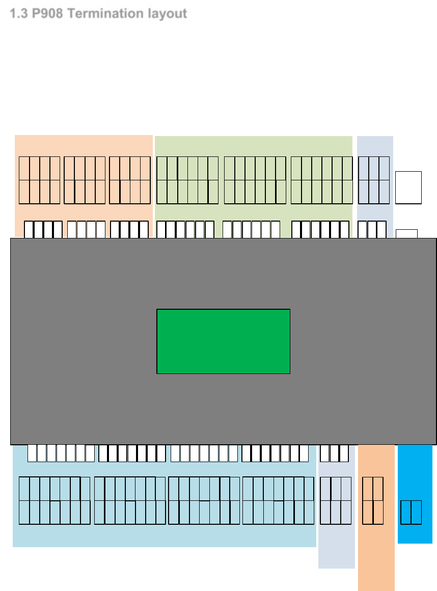
1.3 P908 Termination layout
P908 has 16 readers, 24 inputs, 12 outputs terminal points. It comes with CAN BUS, and LAN Port
connection. Navikey mounted on the controller display vital functional information of the controller. It
doubles up as enrollment readers when necessary.
Relay Input CAN
Wiegand
CAN
RS485
(Dev)
P908
WEBENTRA
Professional Series
R11-
R11+
R12-
R12+
R9-
R9+
R10-
R10+
R7-
R7+
R8-
R8+
R5-
R5+
R6-
R6+
R3-
R3+
R4-
R4+
R1-
R1+
R2-
R2+
G ND
V+
IN23
IN24
G ND
V+
IN19
IN20
IN21
IN22
IN17
IN18
G ND
V+
IN15
IN16
G ND
V+
IN11
IN12
IN13
IN14
IN 9
IN10
G ND
V+
IN7
IN8
G ND
V+
IN 3
IN 4
IN5
IN6
IN 1
IN 2
D0
D1
G ND
V+
D0
D1
G ND
V+
OKL
ERL
OKL
ERL
BUZ BUZ
D0
D1
G ND
V+
D0
D1
G ND
V+
OKL
ERL
OKL
ERL
BUZ BUZ
D0
D1
G ND
V+
D0
D1
G ND
V+
OKL
ERL
OKL
ERL
BUZ BUZ
D0
D1
G ND
V+
D0
D1
G ND
V+
OKL
ERL
OKL
ERL
BUZ BUZ
CAN-
SCN
CAN+
CAN-
SCN
CAN+
AC Fail
Batt
Low
Fire
Alarm
FIRE
GND
BTYL
ACF
DC12V
GND
DC IN
LAN
Port
DEV-
SCN
DEV+
CAN-
SCN
CAN+

Page | 4
1.4 Installer to NOTE
The Installation and Mounting should observe the following:
• The controller should be kept at least 6 feet from any other RF emitting device.
• The controller should be mounted away possible of water leaking location or if in
exterior location sealed to prevent water from seeping into the electronic.
• The controller should be protected from extreme heat and sunlight.
Page | 5
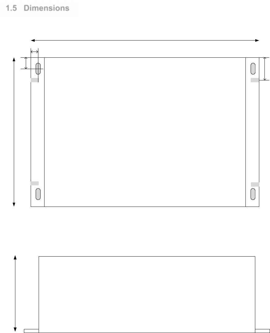
1.5 Dimensions
6mm
10mm
203mm
132mm
20 mm
Top View
63mm
Side View
Page | 6
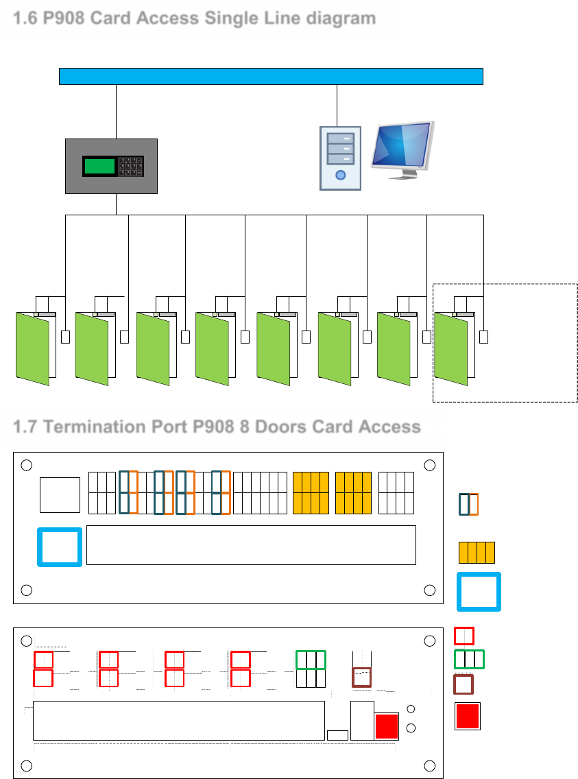
1.6 P908 Card Access Single Line diagram
Typical 8 Doors card access setup with P908 controller and network link back to host software server.
P908
LOCAL AREA NETWORK
Single Door
Entry Exit
Reader
complete with
Door sensor
and Locking
Mechnism
1.7 Termination Port P908 8 Doors Card Access
2
1
INPUT INPUT INPUT RELAY RELAY RELAY
CANbus2
CANbus1
R11-
R11+
R12-
R12+
R9-
R9+
R10-
R10+
R7-
R7+
R8-
R8+
R5-
R5+
R6-
R6+
R3-
R3+
R4-
R4+
R1-
R1+
R2-
R2+
IN22
V+
GND
IN23
IN24
IN21
IN18
V+
GND
IN19
IN20
IN17
IN14
V+
GND
IN15
IN16
IN13
IN10
V+
GND
IN11
IN12
IN9
IN6
V+
GND
IN7
IN8
IN5
IN2
V+
GND
IN3
IN4
IN1
SCN
CAN+
CAN-
SCN
CAN+
CAN-
LAN1
LAN2
P908
2
1
WIEGAND1 WIEGAND3 WIEGAND5 WIEGAND7 USB
CANbus( DEV)
RS485(DEV) POWERFIRE
DETECT ST ATUS
InstaStart
WIEGAND2 WIEGAND4 WIEGAND6 WIEGAND8
FIRE
GND
BTYL
ACF
GND
DC IN
GND
D0
D1
ERL
OKL
BUZ
V+
GND
D0
D1
ERL
OKL
BUZ
V+
GND
D0
D1
ERL
OKL
BUZ
V+
GND
D0
D1
ERL
OKL
BUZ
V+
GND
D0
D1
ERL
OKL
BUZ
V+
GND
D0
D1
ERL
OKL
BUZ
V+
GND
D0
D1
ERL
OKL
BUZ
V+
GND
D0
D1
ERL
OKL
BUZ
V+
DEV +
S CN
DEV -
CA N +
SCN
CAN-
GND
V+
Reader Power
DE V+
SCN
DEV -
RS485 for Readers
FIRE
GND
Fire Alarm Input
DC Input for P908
IN2
IN1
Door Sensor / Exit
Push Button Input
R1-
R1+
R2-
R2+
Relay Output to
Lock
LA N1
Ethernet Port
Page | 7
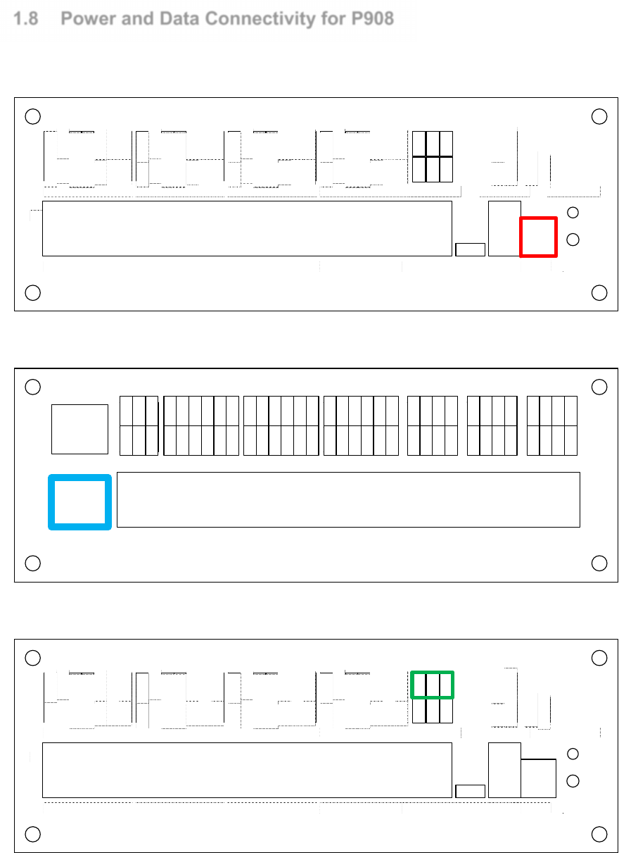
1.8 Power and Data Connectivity for P908
Using DC power supply 13.8VDC 10 Amp, terminate to Connector input label as Power.
P908
2
1
WIEGAND1 WIEGAND3 WIEGAND5 WIEGAND7 USB
CANbus(DEV)
RS485(DEV) POWERFIRE
DETECT STATUS
InstaStart
WIEGAND2 WIEGAND4 WIEGAND6 WIEGAND8
FIRE
GND
BTYL
ACF
GND
DC IN
GND
D0
D1
ERL
OKL
BUZ
V+
GND
D0
D1
ERL
OKL
BUZ
V+
GND
D0
D1
ERL
OKL
BUZ
V+
GND
D0
D1
ERL
OKL
BUZ
V+
GND
D0
D1
ERL
OKL
BUZ
V+
GND
D0
D1
ERL
OKL
BUZ
V+
GND
D0
D1
ERL
OKL
BUZ
V+
GND
D0
D1
ERL
OKL
BUZ
V+
DEV +
S C N
DE V -
CA N+
SCN
CAN-
Communicate to P908 via Ethernet port on LAN1 port.
2
1
INPUT INPUT INPUT RELAY RELAY RELAY
CANbus2
CANbus1
R11-
R1 1+
R12-
R1 2+
R9-
R9+
R10-
R1 0+
R7-
R7+
R8-
R8+
R5-
R5+
R6-
R6+
R3-
R3+
R4-
R4+
R1-
R1+
R2-
R2+
IN22
V+
GND
IN23
IN24
IN21
IN18
V+
GND
IN19
IN20
IN17
IN14
V+
GND
IN15
IN16
IN13
IN10
V+
GND
IN11
IN12
IN9
IN6
V+
GND
IN7
IN8
IN5
IN2
V+
GND
IN3
IN4
IN1
SCN
CAN+
CAN-
SCN
CAN+
CA N-
LAN1
LAN2
Communication RS485 device port to Readers
P908
2
1
WIEGAND1 WIEGAND3 WIEGAND5 WIEGAND7 USB
CANbus(DEV)
RS485(DEV) POWERFIRE
DETECT STATUS
InstaStart
WIEGAND2 WIEGAND4 WIEGAND6 WIEGAND8
FIRE
GND
BTYL
ACF
GND
DC IN
GND
D0
D1
ERL
OKL
BUZ
V+
GND
D0
D1
ERL
OKL
BUZ
V+
GND
D0
D1
ERL
OKL
BUZ
V+
GND
D0
D1
ERL
OKL
BUZ
V+
GND
D0
D1
ERL
OKL
BUZ
V+
GND
D0
D1
ERL
OKL
BUZ
V+
GND
D0
D1
ERL
OKL
BUZ
V+
GND
D0
D1
ERL
OKL
BUZ
V+
D EV +
S CN
DE V -
CA N+
SCN
CAN-
Page | 8
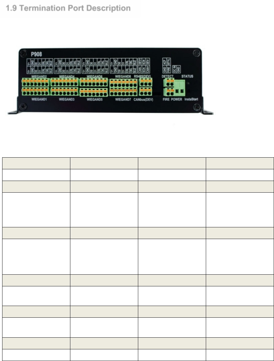
1.9 Termination Port Description
CAN BUS
Description
Access Control
CAN +
,
SCN
,
CAN
-
Future
Future
RS485(DEV)
Description
Access Control
DEV +
SCN
DEV -
RS485 Device Port
Communication port
to Card Reader
WIEGAND
Description
Access Control
+V, GND,
D0,D1,ERL,
OKL,BUZ
Wiegand Reader
connection Port and
Reader Power Point
Connect
wiegand
reader to this port. V+
and GND is also use
for RS485 reader.
FIRE
Description
Access Control
FIRE,GND
Fire signal input
Dry contact from fire
alarm panel
POWER Detection
Description
Access Control
ACF,BYTL
AC Fail, Battery Low
AC Fail,
Battery Low
detection
POWER
Description
Access Control
DC IN, GND
13.8V DC
Power supply to P908
Page | 9
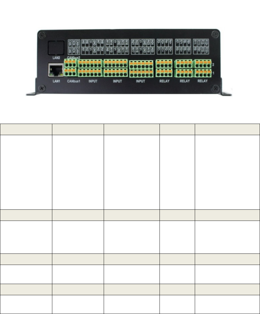
INPUT
Description
Access Control
Aux
INP1
–
INP24
Input 1
-
24
Input
1,3,5,7,9,11,13,15
Exitbutton Input
for Door 1 - 8
Input
2,4,6,8,10,12,14,16
Door Sensor Input
for Door 1 - 8
Input 17
-
24
RELAY
Description
Access Control
R1
+
,R1
-
to
R8+,R8-
Relay Output 1
to
Relay Output 8
Lock output for
Door 1 to Door 8
R9+,R9
-
to
R12+,R12-
CANbus
Description
CANbus1,
CANbus2
Future
LAN
Description
LAN1, LAN2
Ethernet port
Connect to switch
as Host port
LAN2
-
future
h

Page | 10
2.0 Product Specification
Specification P908
Ethernet Host Link 1000Base T x 2
CAN Bus CAN Bus 1 and
CAN Bus 2
(future)
InstaSTART Wizard Yes
DC Power Input 13.8VDC
RS485 (Device Port) Up to 16x Readers
Wiegand Interface 8
Alarm Input/Relay
Output
24/12
Cardholders 150,000 card
capacity
Event Buffers 2,500,000 event
buffer
User Access Groups 1024 group
Holidays 120 holidays date
Weekly Schedules 128 schedules
Data Encryption
Algorithm
128 bit AES or
3DS or SAM
ISO/IEC 7810
Current Consumption
(excluding lock)
Dimensions 230mm x 132mm
x 63mm
Weight 1Kg
Page | 11
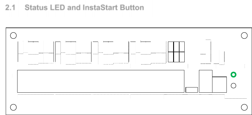
2.1 Status LED and InstaStart Button
P908
2
1
WIEGAND1 WIEGAND3 WIEGAND5 WIEGAND7 USB
CANbus(DEV)
RS485(DEV) POWERFIRE
DETECT STATUS
InstaStart
WIEGAND2 WIEGAND4 WIEGAND6 WIEGAND8
FIRE
GND
BTYL
ACF
GND
DC IN
GND
D0
D1
ERL
OKL
BUZ
V+
GND
D0
D1
ERL
OKL
BUZ
V+
GND
D0
D1
ERL
OKL
BUZ
V+
GND
D0
D1
ERL
OKL
BUZ
V+
GND
D0
D1
ERL
OKL
BUZ
V+
GND
D0
D1
ERL
OKL
BUZ
V+
GND
D0
D1
ERL
OKL
BUZ
V+
GND
D0
D1
ERL
OKL
BUZ
V+
DEV +
S C N
DE V -
CA N+
SCN
CAN-
STATUS LED gives quick glance information about the P908. In operation the STATUS LED blinks
slow in Steady Green. When P908 get a power restart it will blink fast for 30 secs, then when initialize it
will blink slow.
InstarStart Button is use for factory default setting, when unit is power on, depress button will clear all
event, cardholder database, uag config, schedule config.

Page | 12
Reader Connection
Page | 13
Two types of Reader Interface are provided, Wiegand interface and ASIS RS485
protocol. Note that each has a different terminal point and methods.
The P908 Controller auto detect the type of Reader in use. No software or hardware
setting is required.
For Wiegand Interface, 4 standard card bit format is supported. Wiegand 26bit, 35bit,
37bit and 32bit. The 32bit supports the Asis Mifare 4 byte (32bit) Type A Card. A
custom card bit format is available to define by user and must be defined in IBSS
software.
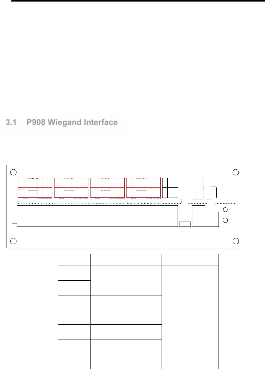
3.1 P908 Wiegand Interface
Wiegand reader termination points are on the right panel label Wiegand 1 to Wiegand
8.
P908
2
1
WIEGAND1 WIEGAND3 WIEGAND5 WIEGAND7 USB
CANbus(DEV)
RS485(DEV) POWERFIRE
DETECT STATUS
InstaStart
WIEGAND2 WIEGAND4 WIEGAND6 WIEGAND8
FIRE
GND
BTYL
ACF
GND
DC IN
GND
D0
D1
ERL
OKL
BUZ
V+
GND
D0
D1
ERL
OKL
BUZ
V+
GND
D0
D1
ERL
OKL
BUZ
V+
GND
D0
D1
ERL
OKL
BUZ
V+
GND
D0
D1
ERL
OKL
BUZ
V+
GND
D0
D1
ERL
OKL
BUZ
V+
GND
D0
D1
ERL
OKL
BUZ
V+
GND
D0
D1
ERL
OKL
BUZ
V+
DEV +
S CN
DE V -
CA N+
SCN
CAN-
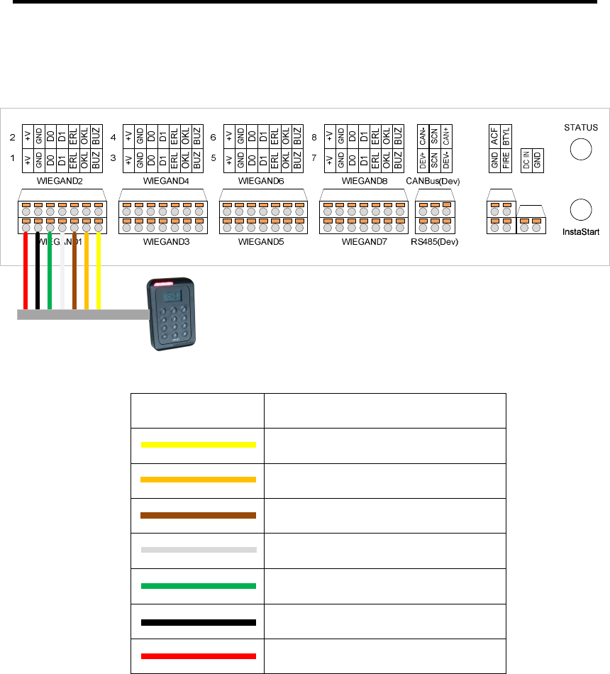
Signal Function For
12V
Supply to reader
Wiegand Reader 1
to Wiegand Reader
8
GND
WDO Wiegand DO Signal In
WD1 Wiegand D1 Signal In
OKL Green LED Out
ERL Red LED Out
BUZ Buzzer Out
Page | 14
The figure below shows the Wiegand Reader connection for P908. The color code for
various wires may differ with Reader vendors. Refer to READERS manufacturer
documentation for more information.
Wire Color Legend Description
Buzzer
Green LED
Red LED
Data 1
Data 0
Ground
12V
Page | 15
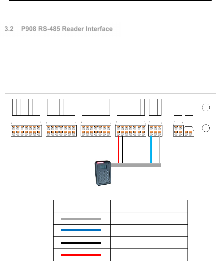
3.2 P908 RS-485 Reader Interface
With ASIS AMR17x series readers, the wiring terminates at (Port Device) on P2. It is
recommended to use 1 pair twisted screen cable for the RS485 network and 1 pair
1.5mm cable for DC12V supply.
Note: The RS-485 connection is polarized; user has to ensure correct polarity during
installation.
WIEGAND1
2
1
4
3
6
5
8
7
BUZBUZ
OKLOKL
ERLERL
D1D1
D0D0
GNDGND
+V+V
BUZBUZ
OKLOKL
ERLERL
D1D1
D0D0
GNDGND
+V+V
BUZBUZ
OKLOKL
ERLERL
D1D1
D0D0
GNDGND
+V+V
BUZBUZ
OKLOKL
ERLERL
D1D1
D0D0
GNDGND
+V+V
BTYLFIRE
ACF
GND
GND
DC IN
InstaStart
STATUS
InstaStart
WIEGAND2
WIEGAND3
WIEGAND4
WIEGAND5
WIEGAND6
WIEGAND7
WIEGAND8
CAN+
CAN-
SCN
RS485(Dev)
CANBus(Dev)
DEV-
DEV+
SCN
Wire Color Legend Description
RS485 -
RS485 +
Ground
12V
It is advisable to ground the screen cable to eliminate possible noise interferences. For
the same communication loop, all screen cable should tie in to make a continuous link.
Do not leave the screen wire un-terminated as it may short accidentally to on-board
components.

Page | 16
Controller Operation

Page | 17
4.1 Anti-Passback Mode
There are three operating modes: Soft Mode , Hard Mode and Time Reset.
Hard Mode: This mode enforces the anti-passback function. Consider the case of a
Cardholder who enters the facility (card read by the entry reader). If the cardholder
exits together with other staff members (without registering) the P908 will have only his
entry record. When the cardholder tries to enter the facility again, P908 will find no
previous exit record and therefore, entry will be denied.
Soft Mode: The anti-passback function limits to monitoring and alarm reporting. In the
soft mode, users are still allowed entry with the event reported.
Time Reset: The anti-pass back time reset mode allow flexible antipass back rule to be
apply based individual operation needs. When antipass violation occurs cardholder will
be denied entry for a preset period of time before access is allow again. Unlike Soft
Mode, time reset mode relax the rule yet remind cardholder of inconvenient encounter
when violate security rules
Note: When APB Hard mode is in use, often users who do not follow the entry/exit
procedure may assume the system malfunctions when entry is denied. Therefore it is
important all Cardholders be aware and follows the procedure.
Page | 18
Mode Function
Disable Disable the APB Mode
Soft Allow Entry/Exit with event reporting when there is APB violation
Hard Disallowed Entry/Exit with event reporting when there is APB violation
Time reset
Time Disallowed Entry/Exit with event report when APB violation
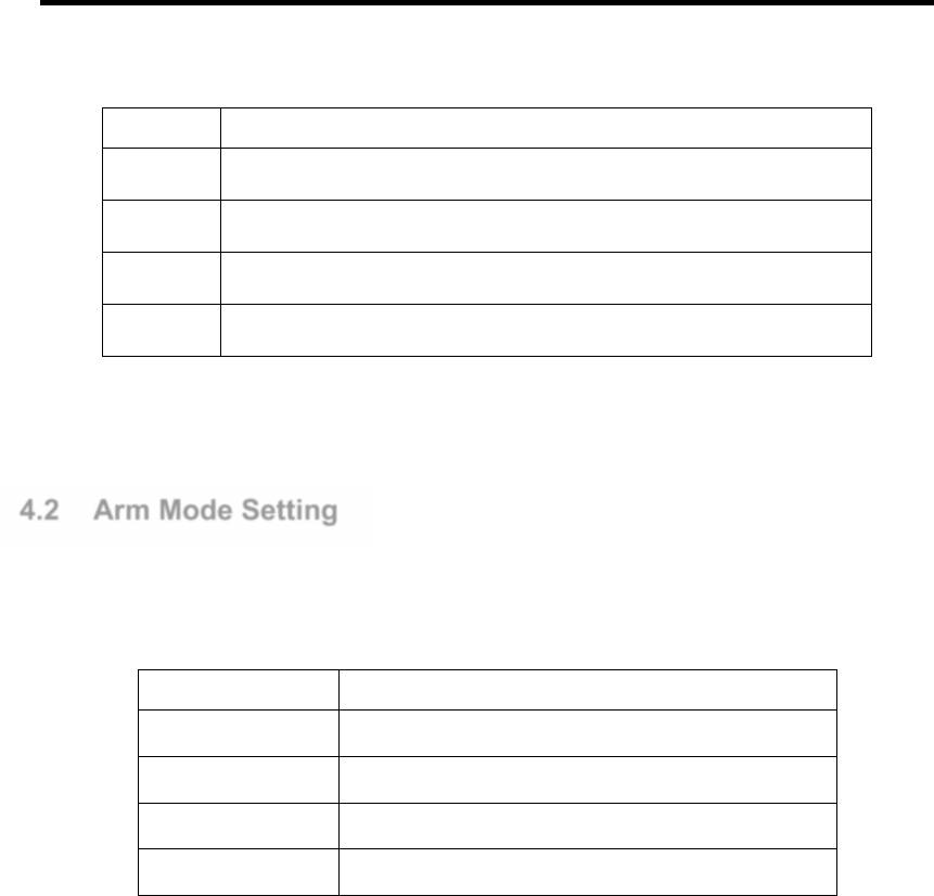
4.2 Arm Mode Setting
P908 has 4 Arm Modes setting. This may be set via the Web UI.
Mode Function
Arm Normal operation
Lock Permanent lock the door
Unlock Permanent unlock the door
Disarm by schedule
Unlock the door during the time zone set in schedule
Arm Mode:
This mode is for normal operation. The door will be locked and monitored until a valid
card is presented and P908 unlock the door with a time defined by Unlock Time setting
in the Reader Configuration.
Lock Mode:
This will permanently lock the door. It denies entry to all valid Cardholders. It remains in
this mode until changed.
Unlock Mode:
This mode will unlock the door all the time until the mode is changed.
Page | 19
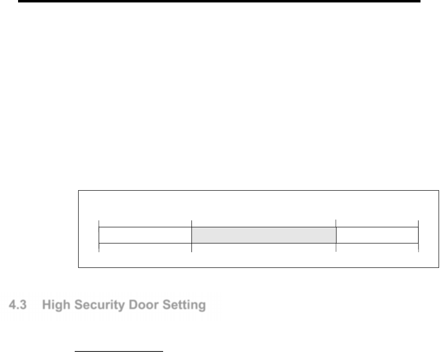
Disarm By Schedule Mode: (Timed unlock)
This mode unlocks the door during active period of the DisArm Schedule. It can be set
from IBSS.
The table below is an example where a time zone in the schedule is set to “09:00 to
17:00”. Prior to 9:00 AM, the door control in Arm mode, this means access via a valid
card. From 9:00 AM to 5:00 PM, the door is unlocked for free access. After 5:00 PM,
door is lock and under Arm Mode again.
Door is unlocked and
no event report
DisArmBySchedule Mode
00:00
09:00
16:59
23:59
Arm
Arm
DisArm
4.3 High Security Door Setting
Multi Card Access
For highly secured areas, it may require the presence of more than one staff to unlock
the door. P908 allows multiple cards to grant access. This mode may be set from the
IBSS software.
P900 allows multi-card access with up to 4-cards, and a number of authorized cards
must be present before access is granted.
For example, if the number of cards is set to “4”, after the 1
st
card is read, the Green
LED will blink at a faster rate. This indicates the reader expects the next card. Until all
the 4 valid cards are read, P908 unlocks the door.
Note: Please note that the multi-card reader only check the validity of the card being
read, the sequence of the cards presentation does not matter.
The following are situations possible for error conditions in multi-card operation. Users
have to exercise caution to avoid these situations.
Timeout:
There is a time out period of 15 sec for each user to present card. If the next card is not
presented within next 15 seconds then the P908 will void the operation. The time out
period is fixed at 15 sec. and cannot be changed.
Invalid card:
If any of the cards presented is an invalid card, then the P908 will void the operation.

Page | 20
PIN Access
Pin Access is requiring for Main entrance to a facility. Using Pin Access at Main
Entrance ensure the right person is gaining access as PIN is issue as a password to
individual so only authorize personal with the right credential knows. Pin Access can be
set to operate for 24/7 or in a more relax environment only during off peak hour so that
as to ensure integrity and availability.
Page | 21
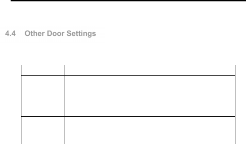
4.4 Other Door Settings
There are some parameters that affect the door control setting.
Mode Function
Unlock Time The door release time upon presenting a valid card
Pre-Alarm Time
Warning beeps from the reader buzzer after the time expires
DOTL Reader buzzer sounds to indicate that the door is opened for too long
Toggle Mode Door operate in toggle mode with card flash, suitable for auditorium
Door interlock Man-trap operation. One room 2 doors, only 1 door allow to open.
Unlock Time:
This is the time that P908 will unlock the door upon a valid card presentation. It can be
set from 0 to 255 seconds.
Pre-Alarm Time:
P908 connected reader will sound the buzzer with a warning tone when the door is held
open beyond this time. It can be set from 0 to 255 seconds. This time period should
always be set longer than Unlock Time. No alarm event is reported if the door closes
before Pre-Alarm Time expires, the warning tone will stop once the door is closed.
DOTL:
This is known as Door Open Too Long. The P908 connected reader will sound buzzer
continuously when the door is held open longer than his period. It can be set from 1 to
255 seconds. This time setting should always be longer than Unlock Time and Pre-
Alarm Time. A DOTL alarm event is reported when an alarm tone is triggered. The
alarm tone will stop once the door is closed.
Toggle Mode:
When set to this mode the door when toggle from open to close between valid card
flash. In this mode door have to be disarm by 24hrs schedule, and Pre-alarm and
DOTL will be disable.
Door interlock:
Man-trap operation. 2 door program to be monitoring each other status. If door 1 door
sensor is activated, door 2 lock output will not be activated by card flash on Reader 2 or
exit push button on Reader 2.

Page | 22
Input
Page | 23
5.1 Input Configuration
This section provides information on input functions and wiring connection.
The inputs 1 to 24 are software configurable to provide flexibility to suit application
requirements. These inputs have factory default setting when shipped.
There is 200ms noise filtering for inputs 1 to 24. When input is activated within 200ms
and then restored back to normal, the activation of this input will be ignored.
5.2 Input Type
Inputs 1 to 24 are analog input designed to detect 4-state events in the “Supervised
Mode”. It may be configured to detect 2-state events in the “Non-Supervised Mode”.
DIP Switch 1- Position 6 “LSS” - ON for supervised mode and OFF for non-supervised
mode.
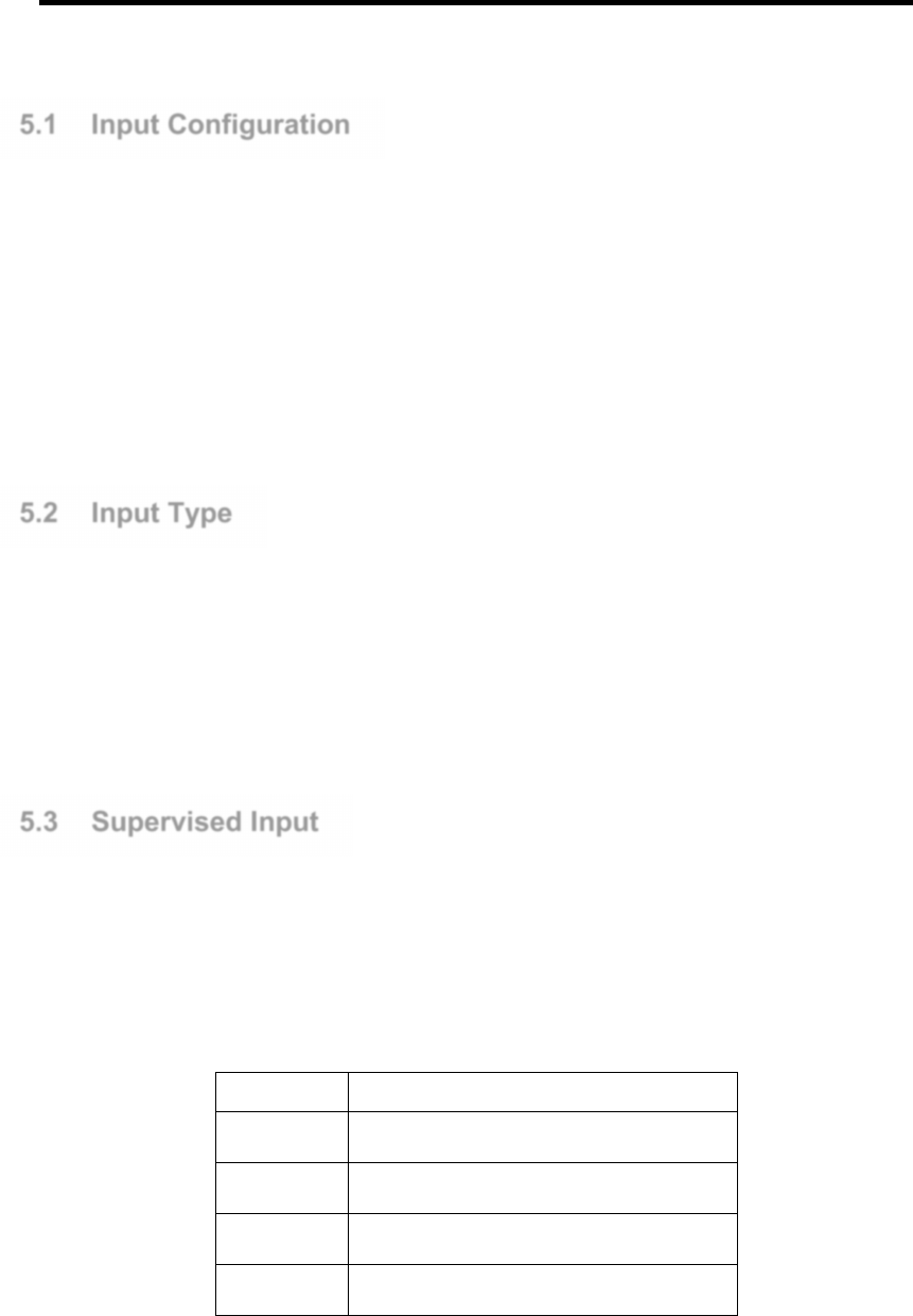
5.3 Supervised Input
In Supervised Input Mode, the end of line resistors must be used to terminate the line
(refer to Figure 6.1). Line fault conditions can be monitored in addition to the device
status. All these event occurrences are reported to the IBSS management software.
Mode Function
Normal Normal condition; device contact - Closed
Activate Input device triggered - Open
Open Circuit
Input line is open circuit
Short Circuit Input line is short circuit

Page | 24
Normal State:
This state indicates a NC external device is in normal condition.
Activate State:
This state indicated the NC external device is triggered i.e. become open circuit.
Open Circuit:
This indicates the line connection to the external device has been broken/open circuit.
Short Circuit:
This indicates that the line connection is short circuit.
5.4 End of Line Resistor
For operation in the line Supervised Mode, end of line resistors is required. This
establishes different voltages at the input depending on the device status and line fault
conditions. The input circuit compares the voltage differential on the line to internal
thresholds to determine the line status. The end of line resistor value shall be 10Kohm.
The figure below shows the typical connection for Exit Button 1 and Door Sensor 1. It
also applies to inputs 5 to 8.
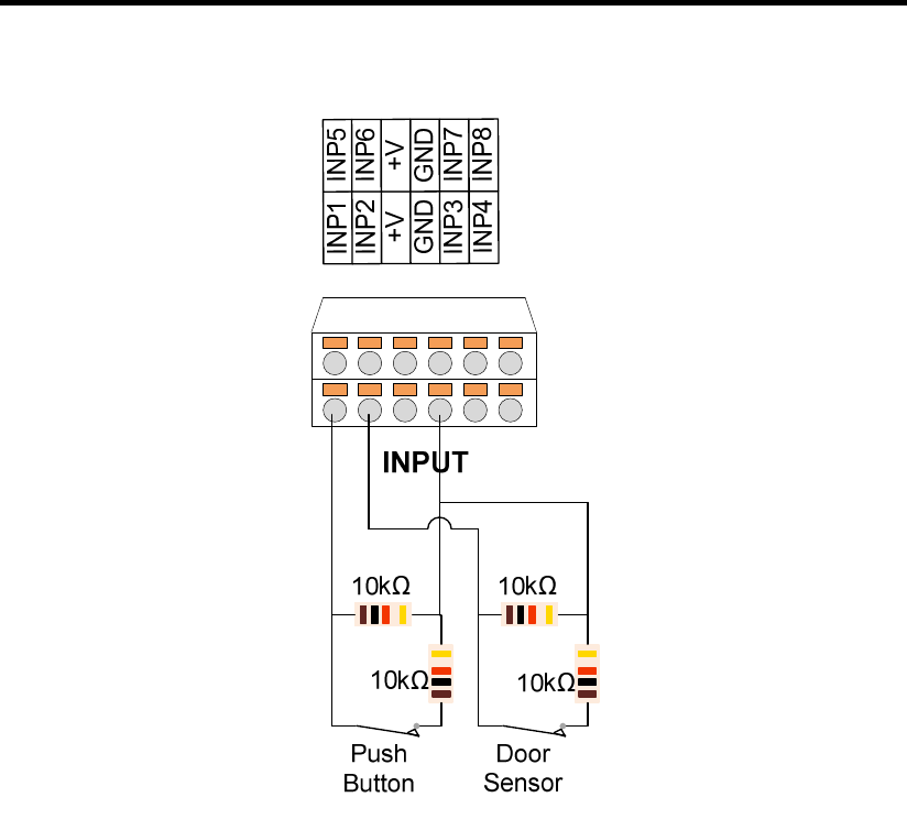
Page | 25
Note: Use Normally Closed (NC) type input devices, such as Exit Button, Door Contact,
etc., because Normally Open (NO) device is not suitable. If the device is faulty on open
circuit, no detection is possible.
Page | 26
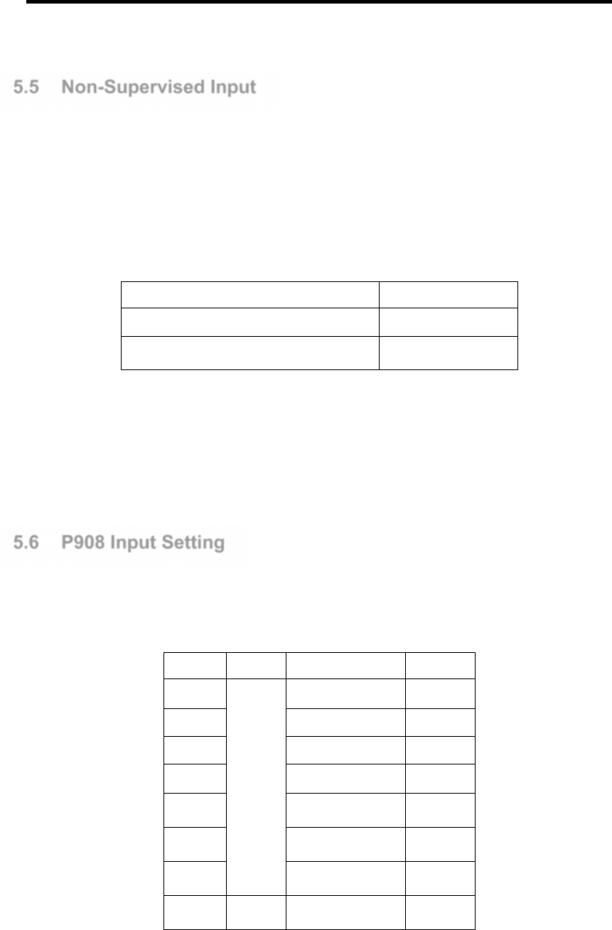
5.5 Non-Supervised Input
If the requirement is to detect ON/ OFF signal and line fault monitoring is not required,
non-supervised mode may be used. To enable this mode, set DIP SW 1 and Switch 6
(LSS) should be turned “OFF”. No end of line resistor is required.
Non-supervised input setting can detect 2 states:
State Function
Normal (Device in NC) Normal condition
Activate (Device activates in open circuit)
Input line is triggered
Note: Setting of this switch applies to all analog 8 inputs. If there is any input requires
line supervision, then ALL inputs have to operate in the same mode. This setting has
no effect on Fire Alarm input.
5.6 P908 Input Setting
When P908 is configured as access control, the following default input settings applies:
Input Header
Default Function
For
Input 1
INPUT
Exit Button Reader 1
Input 2 Door Sensor Reader 1
Input 3 Exit Button Reader 2
Input 4 Door Sensor Reader 2
Input 5 Exit Button Reader 3
Input 6 Door Sensor Reader 3
Input 7 Exit Button Reader 4
Input 8 Door Sensor Reader 4

Page | 27
Input 9 Exit Button Reader 5
Input 10
Door Sensor Reader 5
Input 11
Exit Button Reader 6
Input 12
Door Sensor Reader 6
Input 13
Exit Button Reader 7
Input 14
Door Sensor Reader 7
Input 15
Exit Button Reader 8
Input 16
Door Sensor Reader 8
Input 17
Input zone Input
Input 18
Input zone Input
Input 19
Input zone Input
Input 20
Input zone Input
Input 21
Input zone Input
Input 22
Input zone Input
Input 23
Input zone Input
Input 24
Input zone Input
5.7 Input Arm Setting
Input 17 to Input 24 of P908 can be wired to monitoring device with Dry contact
normally close input for triggering monitoring.
Mode Function
Arm Normal operation
Disarm Disable arm operation
Disarm By Schedule
Disarm during the time period defined by the Disarm Schedule

Page | 28
Arm:
This is the default mode and all inputs activation will have alarm event report back to
IBSS.
Disarm:
This is to disable the alarm function. Inputs activation will not have any alarm event
report to the IBSS.
Disarm By Schedule:
This mode is to disable the input alarm function during the time zone defined by the
Schedule.
If the time zone is set to “09:00 – 16:59”, the table below illustrates the operation.
Input Unarmed and
no event report
DisarmBySchedule Mode
00:00
09:00
16:59
23:59
Arm
Arm
Disarm
Prior to 09:00, the input is in “Arm” mode, this means any activation of the input will
trigger an alarm event.
From 9:00am to 17:00pm P908 is unlocked by “Disarm” mode. No alarm event will be
reported. At 17:00, P908 is revert back to arm mode.

Page | 29
Output
Page | 30
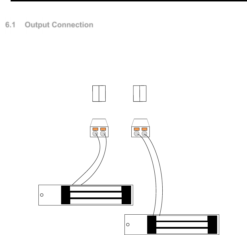
6.1 Output Connection
This section provides information on the Output connection to external devices. The
Outputs has software configurable settings.
The following figure shows the P908 output connection to EM Lock.
RELAY1 RELAY2
OP1-
OP1+
OP2-
OP2+
Page | 31
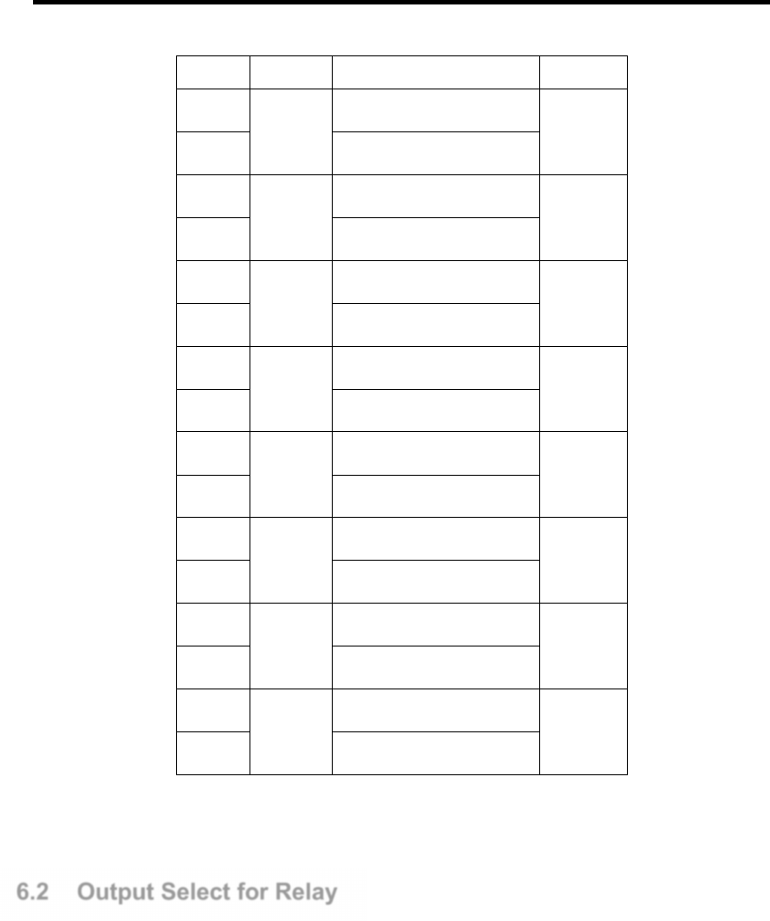
Output
Header Default Function Defaults
OP1 +
RELAY1
Door Lock Output 1 (+ve)
Reader 1
OP1 - Door Lock Output 1 (-ve)
OP2+
RELAY2
Door Lock Output 2 (+ve)
Reader 2
OP2- Door Lock Output 2 (-ve)
OP3+
RELAY3
Door Lock Output 3 (+ve)
Reader 3
OP3- Door Lock Output 3 (-ve)
OP4+
RELAY4
Door Lock Output 4 (+ve)
Reader 4
OP4- Door Lock Output 4 (-ve)
OP5+
RELAY5
Door Lock Output 5 (+ve)
Reader 5
OP5- Door Lock Output 5 (-ve)
OP6+
RELAY6
Door Lock Output 6 (+ve)
Reader 6
OP6- Door Lock Output 6 (-ve)
OP7+
RELAY7
Door Lock Output 7 (+ve)
Reader 7
OP7- Door Lock Output 7 (-ve)
OP8+
RELAY8
Door Lock Output 8 (+ve)
Reader 8
OP8- Door Lock Output 8 (-ve)
RELAY1 to RELAY8 are set by default to function as door lock output for Reader 1 and
Reader 8. All relay function as 12V voltage output normally open relay setting
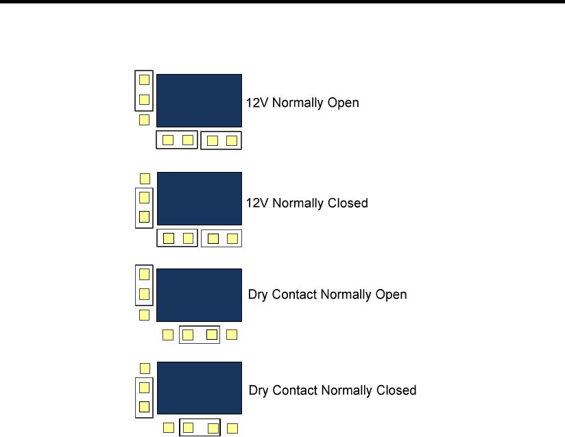
6.2 Output Select for Relay
Relay can be set to different output configurations via jumper settings:
• NO (Normally Open)
• NC (Normally Close)
• 12V output in NO configuration
• 12V output in NC configuration
The 4-pin header is for 12VDC or dry-contact (voltage free) output setting. The 3-pin
header is for normally closed (NC)/ normally open (NO) output setting. The following
figure depicts the output setting for Relays. There are 4-pin header and 3-pin header by
the side of each relay for jumper selection.
Page | 32
Note: Contact rating at 30V, 1A
The supply voltage to Relay is unregulated 12VDC with maximum of 1A. This is
adequate for most locking devices. The factory default is 12V Output in NO
Configuration.
Page | 33
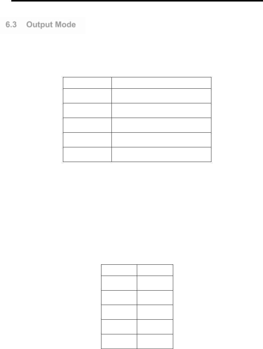
6.3 Output Mode
An output may be set in any of the 5 Output modes. User must set the output mode to
suit the application
.
Output Mode Function
Latch Output in activate mode
Toggle Output set to toggle mode
Pulse Output is in pulse mode
Cycle Output cycles with ON and OFF time
Act By Schedule
Output activated by a schedule
Example: Input 3 is set to trigger Output 1
Latch mode:
When Input 3 is in normal state, Output 1 will be in “OFF” state. When Input 3 activates,
Output 1 will now switch to “ON” state, it remains at this state even after Input 3 is
restored to normal.
Input 3 Output 1
Normal OFF
1
st
Activate
ON
2
nd
Activate
Remain ON
3
rd
Activate Remain ON
4
th
Activate Remain ON
Page | 34
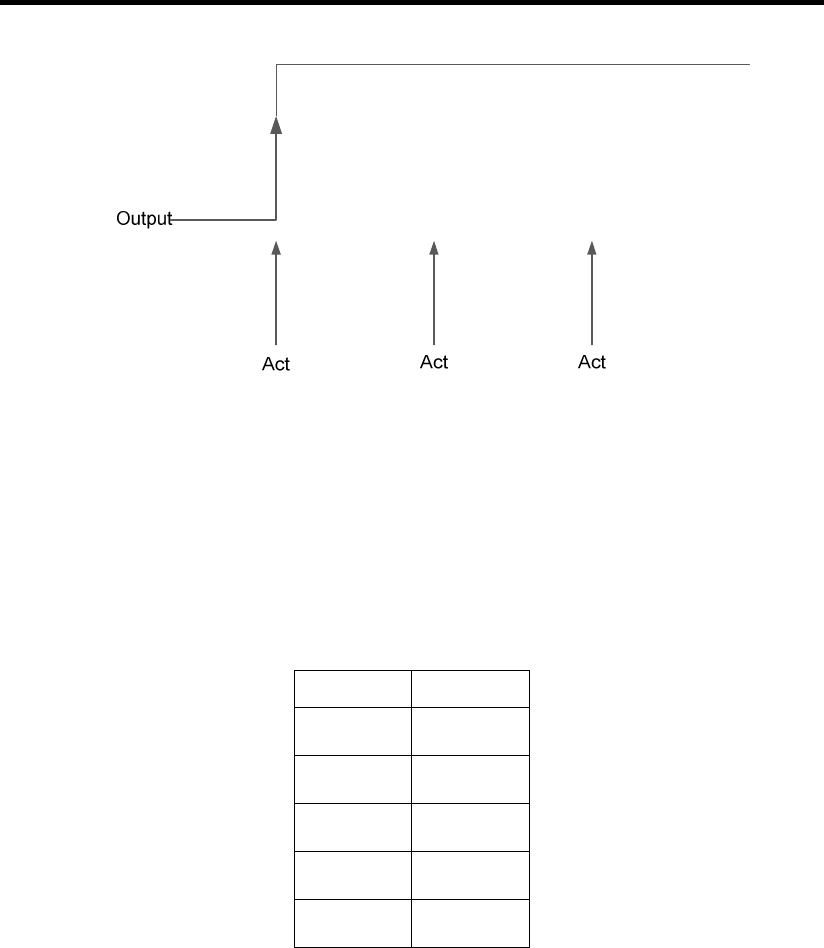
Toggle mode:
The output toggles between “On” and “OFF” states upon each input activation (or
triggering). When Input 3 returns to normal state after each trigger, Output 1 remains at
the state until the next activation.
Input 3 Output 1
Normal OFF
1
st
Activate
ON
2
nd
Activate
OFF
3
rd
Activate ON
4
th
Activate Remain ON
Page | 35
Figure 7.5 Toggle Mode Operation
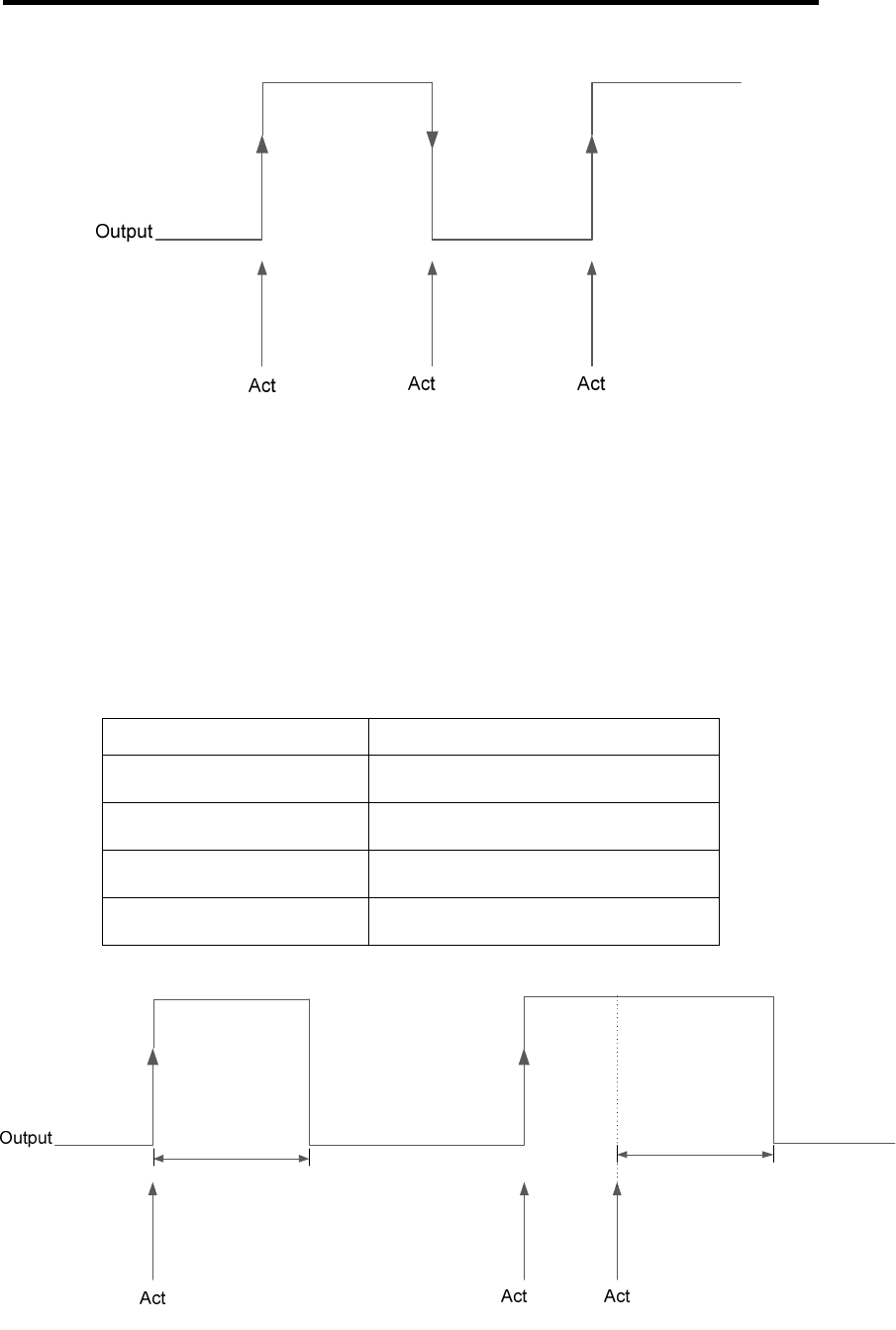
Pulse mode:
Upon Input 3 activate, the Output 1 turns “ON” for a preset period (1 to 255 sec) and
then “OFF” again.
Input 3 Output 1
Normal OFF
1
st
Activate Turn “ON” for 10 sec, then turn “OFF”
2
nd
Activate Turn “ON” for 10 sec, then turn “OFF”
3
rd
Activate within 10 seconds
Pulse Output period extended by 10 sec
Page | 36
Figure 7.6 Pulse Mode Timing Operation
Note: An input activation before the pulse period expires extends the pulse period for
the next 10 seconds.
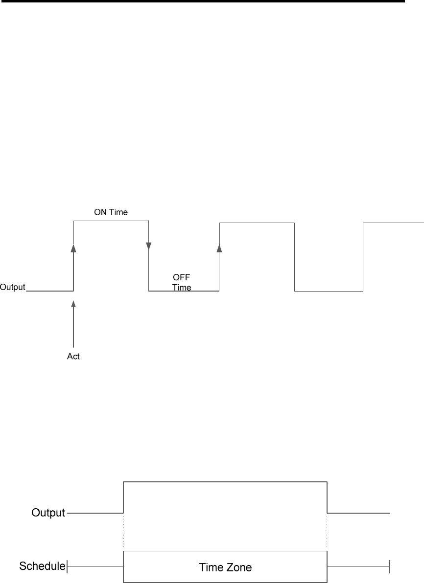
Cycle Mode:
The Output cycles continuously with an “On Time” and “Off Time” (between 1 – 255
seconds). The cycle mode stops only when output is deactivated.
Act by Schedule:
This is timer control function by a weekly Schedule. The Output is activated by the Time
Zones set in the Schedule. When there is activation prior to the start time, Output turns
ON and will be turned OFF at the end time of the Time Zone.
Page | 37
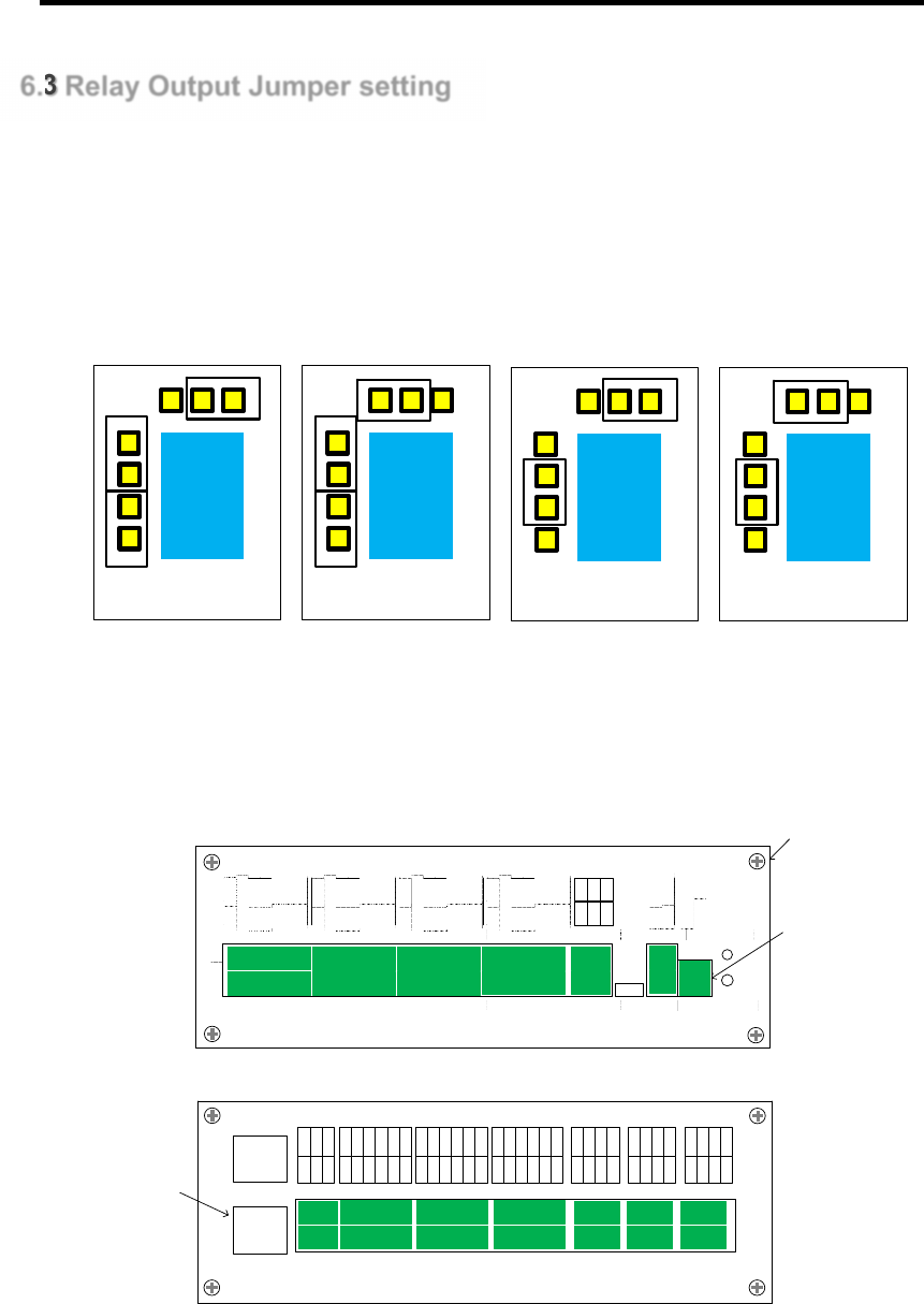
6.3 Relay Output Jumper setting
P908, relay output can operate in 4 states.
Normally open 12V
Normally Close 12V
Normally open Dry contact
Normally Close Dry contact
Normally close 12V Normally open 12V Normally close Dry
Contact
Normally open Dry
Contact
P908 relay setting can be change, but required dismantling of the case.
Steps to dismantle P908 casing
Remove all Green connectors on front and back panels, remove LAN cable.
P908
2
1
WI EGAND1 WIEGAND3 WIEGAND5 WIEGAND7 U SB
CANbu s(DEV)
RS485(DEV) POWERFI RE
DET ECT STATU S
InstaStart
WI EGAND2 WIEGAND4 WIEGAND6 WIEGAND8
FIRE
GND
BTYL
ACF
GND
DC IN
GND
D0
D1
ERL
OKL
BUZ
V+
GND
D0
D1
ERL
OKL
BUZ
V+
GND
D0
D1
ERL
OKL
BUZ
V+
GND
D0
D1
ERL
OKL
BUZ
V+
GND
D0
D1
ERL
OKL
BUZ
V+
GND
D0
D1
ERL
OKL
BUZ
V+
GND
D0
D1
ERL
OKL
BUZ
V+
GND
D0
D1
ERL
OKL
BUZ
V+
DE V+
SCN
DEV-
CA N +
SCN
CA N-
2
1
INPUT INPUT INPUT RELAY RELAY REL AY
CANbu s2
CANbu s1
R11-
R11+
R12-
R12+
R9-
R9+
R10-
R10+
R7-
R7+
R8-
R8+
R5-
R5+
R6-
R6+
R3-
R3+
R4-
R4+
R1-
R1+
R2-
R2+
IN22
V+
GND
IN23
IN24
IN21
IN18
V+
GND
IN19
IN20
IN17
IN14
V+
GND
IN15
IN16
IN13
IN10
V+
GND
IN11
IN12
IN9
IN6
V+
GND
IN7
IN8
IN5
IN2
V+
GND
IN3
IN4
IN1
SCN
CAN+
CAN-
SCN
CAN+
CAN-
LAN1
LAN2
Screw
Green Connector
LAN CABLE
Unscrew all four screws from front panels and remove front panels
Slide out the PCBA

Page | 38
Set the jumper setting as requirement
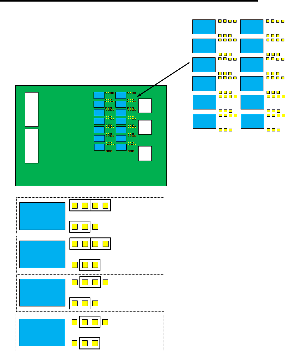
Page | 39
10 12
11 9
6 8
7 5
2 4
3 1
1
1
1
1
Normally
Open
12V
Normally
Close
12V
Normally
Open Dry
Contact
Normally
Close Dry
Contact
Slide back the PCBA place back front panels
Plug back all connector then screw back the 4 screw from front panel
Page | 40
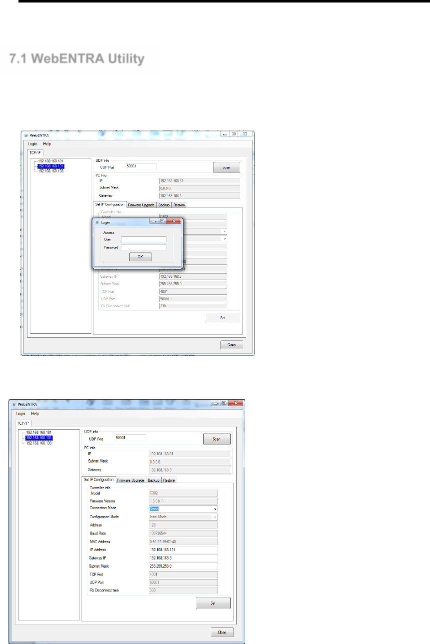
7.1 WebENTRA Utility
WebENTRA utility is use for changing of network parameter (IP address, Subnet, Gateway. Use Scan
Button to search for Local network connected P908
To start Login to connected controller for configuration. UserID: admin, Password: admin
To change Network parameter, edit the IP Address field and click Set.
Page | 41
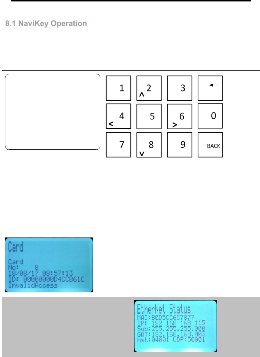
8.1 NaviKey Operation
Navikey allow localize configuration of Controller without the need to external peripherals. All is needed
is finger to touch the keypad to get info of controller and make configuration.
Features of Navi key includes, live event display, device control, card enroll (csn only), controller
parameter setting.
Navigate the Navikey using the keypad KEY 2 = UP, KEY 8 = DOWN, KEY 4 = LEFT, KEY 6 = RIGHT.
Back and Enter KEY is use to get into an function or exit from the function.
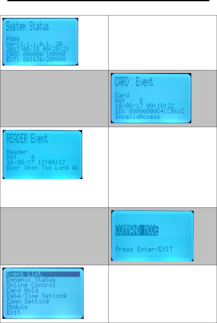
Default Screen of Navi key always show latest
controller generated event
From default screen press [KEY 4] 2 x to view it
configured network parameters.
Page | 42
From default screen press [KEY 4] 3 x to view
system operating parameters.
Firmware version
Date / Time
Card
Event
To view recent Card event
Press [[<4 key]] left 4 times.
Use key 2 to navigate up or key 8 to navigate
down.
To exit press BACK key
To view recent Reader event
Continue from Card Event after the BACK key
press <4 key will bring to Output, press BACK key
and press <4 key, will bring to Input Event, press
BACK and press <4 key will bring to READER
event
Use key 2 to navigate up or key 8 to navigate
down.
To exit press BACK key
To get into Command Mode press <4 key 1 time.
Press ENTER key
You will be prompt with password press 123456
and press ENTER key
In Command Mode Navigate Up using 2 KEY or
Down using 8 KEY to exit press BACK KEY
Press ENTER KEY to get into the selected
function
Page | 43
In Event List Navigate Up using 2 KEY or Down
using 8 KEY to exit press BACK KEY
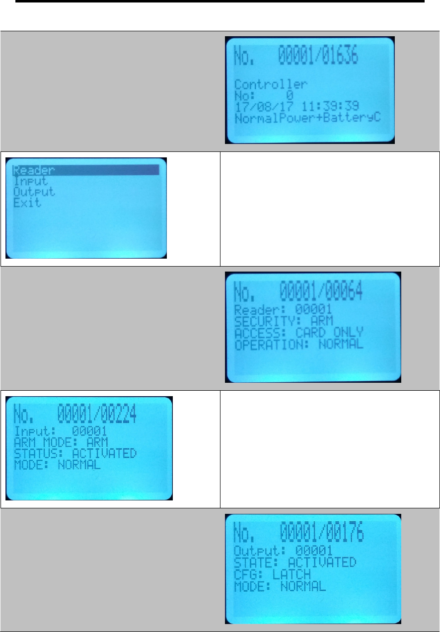
In Event List Navigate Up using 2 KEY or Down
using 8 KEY to exit press BACK KEY
Press ENTER to view device dynamic status
In Dynamic Status: Reader Navigate Up using 2
KEY or Down using 8 KEY to exit press BACK
KEY
In Dynamic Status: Input Navigate Up using 2
KEY or Down using 8 KEY to exit press BACK
KEY
In Dynamic Status: Output Navigate Up using 2
KEY or Down using 8 KEY to exit press BACK
KEY
Page | 44
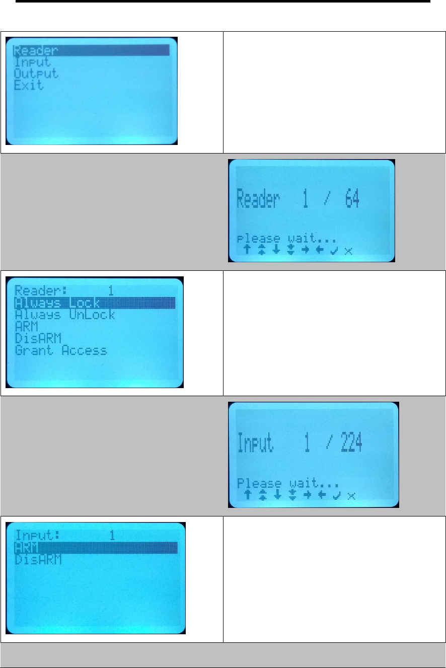
In Online Control Navigate Up using 2 KEY or
Down using 8 KEY to exit press BACK KEY
Press enter KEY to control the device
In Online Control : Reader Navigate Up using 2
KEY or Down using 8 KEY to exit press BACK
KEY
Press ENTER KEY to select the reader to control
In Online Control : Reader Navigate Up using 2
KEY or Down using 8 KEY to exit press BACK
KEY
Press ENTER KEY to issue the selected
command to control the reader
In Online Control : Input Navigate Up using 2 KEY
or Down using 8 KEY to exit press BACK KEY
Press ENTER KEY to select the Input to control
In Online Control : Input Navigate Up using 2 KEY
or Down using 8 KEY to exit press BACK KEY
Press Enter KEY to issue the selected command
to control the input
Page | 45
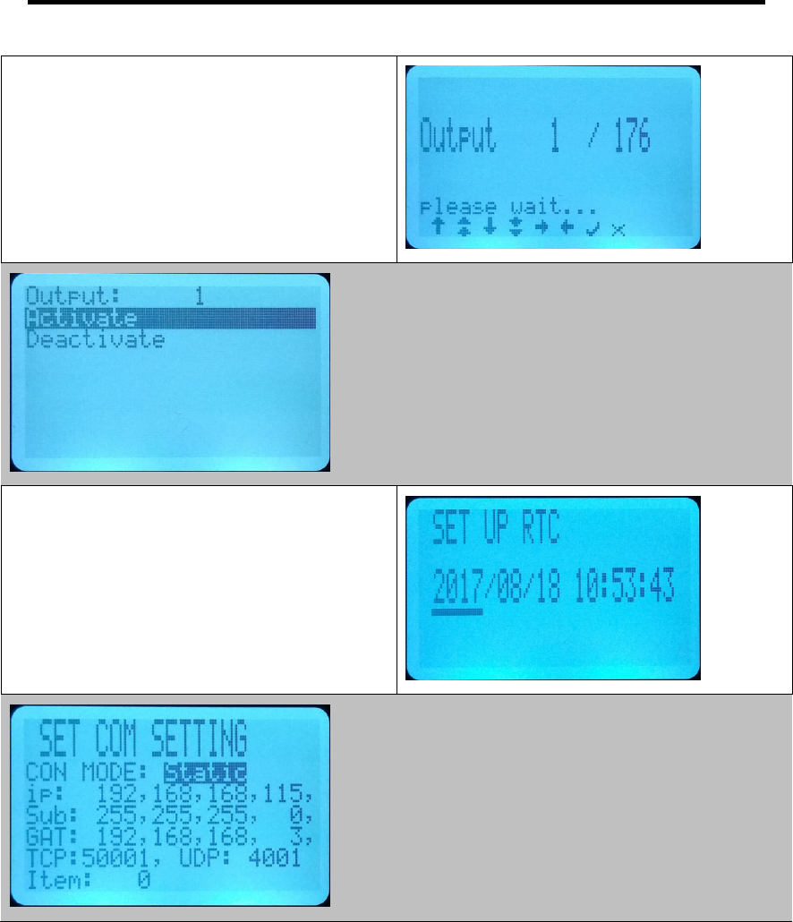
In Online Control : Output Navigate Up using 2
KEY or Down using 8 KEY to exit press BACK
KEY
Press ENTER KEY to select the Output to control
In Online Control : Output Navigate Up using 2
KEY or Down using 8 KEY to exit press BACK
KEY
Press ENTER KEY to issue the selected
command to control the Output
In Date/Time Setting : Navigate using <4 KEY or
>6 KEY to select item to change. Use 2 KEY to
select UP or 8 KEY to select DOWN
Press ENTER KEY to confirm changes and exit
In Comm Setting : Navigate using <4 KEY or >6
KEY to select item to change. Use 2 KEY to
select UP or 8 KEY to select DOWN
Press ENTER KEY to confirm changes and exit