Askey Computer RT210W Wireless Router User Manual users manual
Askey Computer Corp Wireless Router users manual
users manual
Wireless Broadband Router
User Manual
No part of this publication may be reproduced in any form by any
means without the prior written permission. Other trademarks or
brand names mentioned herein are trademarks or registered
trademarks of their respective companies.
Jan 2003, Draft Version F/W:2.02.00
NOTE
This equipment has been tested and found to comply with the limits for a
Class B digital device, pursuant to Part 15 of the FCC Rules. These limits are
designed to provide reasonable protection. This equipment generates, uses
and can radiated radio frequency energy and, if not installed and used in
accordance with the instructions, may cause harmful interference to radio
communications. However, there is no guarantee that interference will not
occur in a particular installation If this equipment does cause harmful
interference to radio or television reception, which can be determined by
turning the equipment off and on, the user is encouraged to try to correct the
interference by one or more of the following measures:
-Reorient or relocate the receiving antenna.
-Increase the separation between the equipment and receiver.
-Connect the equipment into an outlet on a circuit different from that to which
the receiver is connected.
-Consult the dealer or an experienced radio/TV technician for help.
Changes or modifications not expressly approved by the party responsible for
compliance could void the user‘s authority to operate the equipment.
FCC Radiation Exposure Statement
This equipment complies with FCC RF radiation exposure limits set
forth for an uncontrolled environment. This equipment should be
installed and operated with a minimum distance of 20 centimeters
between the radiator and your body.
i
Contents
1 Introduction ..................................................1
1.1 Overview........................................................................1
1.2 Features ........................................................................1
1.3 Package Contents .........................................................2
1.4 System Requirements ...................................................3
2 Hardware Description & Installation.............5
2.1 Physical Outlook............................................................5
Front Panel..................................................................5
Rear Panel and Connectors........................................6
2.2 Hardware Connection....................................................7
Choosing a Place for the Router .................................7
Connecting the Wireless Broadband Router ...............7
3 Setting Up Ethernet/WLAN Client ..............11
3.1 Setting up Ethernet Client............................................11
For Windows 98/ME..................................................12
For Windows NT .......................................................13
For Windows 2000 ....................................................14
3.2 Setting up Wireless Client............................................15
3.3 Checking Connection with the Router..........................16
4 Web Configuration .....................................17
4.1 Accessing Web-Based Configuration Utility.................17
To enable Your Settings.............................................18
4.2 Viewing System Status ................................................19
4.3 Configuration for NAT Routing Mode ...........................20
WAN Configuration for NAT Routing Mode ...............22
LAN Configuration for NAT Routing Mode.................27
Viewing Current DHCP Assignments.........................28
4.4 Configuration for Bridge Mode.....................................29

Wireless Broadband Router User Manual
ii
4.5 Wireless LAN (2.4G) Configuration..............................32
4.6 Filters...........................................................................37
Specifing Your IP Filter Rules ....................................37
Filter Types................................................................38
Filter Scenario of the Wireles Broadband Router......39
Viewing Filter Log......................................................40
Other Firewall Settings..............................................40
4.7 Forwarding...................................................................42
Setting Up Forwarding Entries ..................................42
If you have a Web server on your network… ............43
4.8 Administration ..............................................................45
5 Specification...............................................49
5.1 Hardware .....................................................................49
5.2 Software ......................................................................50
iii
Safety Instructions
Installing
• Use only the type of power source indicated on the
marking labels.
• Use only the power adapter supplied with the product.
• Do not overload wall outlet or extension cords as this may
increase the risk of electric shock or file. If the power cord
is frayed, replace it with a new one.
• Proper ventilation is necessary to prevent the product
overheating. Do not block or cover the slots and openings
on the device, which are intended for ventilation and
proper operation. It is recommended to mount the product
with a stack.
• Do not place the product near any source of heat or
expose it to direct sunshine.
• Do not expose the product to moisture. Never spill any
liquid on the product.
• Do not attempt to connect with any computer accessory or
electronic product without instructions from qualified
service personnel. This may result in risk of electronic
shock or file.
• Do not place this product on an unstable stand or table.
Using
• Power off and unplug this product from the wall outlet
when it is not in use or before cleaning. Pay attention to
the temperature of the power adapter. The temperature
might be high.
• After powering off the product, power on the product at
least 15 seconds later.
• Do not block the ventilating openings of this product.
• When the product is expected to be not in use for a period
of time, unplug the power cord of the product to prevent it
from the damage of storm or sudden increases in rating.
Servicing

Wireless Broadband Router User Manual
iv
Do not attempt to disassemble or open covers of this unit yourself.
Nor should you attempt to service the product yourself, which may
void the user’s authority to operate it. Contact qualified service
personnel under the following conditions:
• If the power cord or plug is damaged or frayed.
• If liquid has been spilled into the product.
• If the product has been exposed to rain or water.
• If the product does not operate normally when the
operating instructions are followed.
• If the product has been dropped or the cabinet has been
damaged.
• If the product exhibits a distinct change in performance.
v
About This User Manual
For brevity, throughout this manual the “Wireless Broadband
Router” is referred to as “the router” or “the device” and following
terms or abbreviations are used interchangeably:
• Access Point-AP
• Wireless LAN-WLAN
• Ethernet network-LAN-network
This User Manual contains information on how to install and
configure your Wireless Broadband Router to get your network
started accessing the Internet. From now on, we will guide you
through the correct configuration steps to get your device up and
run.

1
1 Introduction
1.1 Overview
Thank you for choosing this Wireless Broadband Router. The
Wireless Broadband Route features a wireless Access Point, a
4-port LAN switch and a WAN port, which extends your existing
broadband Cable/ADSL connection. It allows the broadband
connection to be shared through either the IEEE 802.11g Access
Point feature or the 10/100Base-TX Ethernet switch, which also
eliminates the purchase of additional hub or switch. Now your
wired and wireless network are integrated to enjoy various
bandwidth-consuming applications over the Internet.
With the support of new emerged 802.11g standard, the Access
Point provides data transfer of up to 54 Mbps, up to 5 times faster
than 802.11b. Since 802.11g operates on the same frequency of
2.4 GHz as 802.11b, it is backwards compatible with existing Wi-Fi
devices. The benefit is that you can preserve the existing 802.11b
infrastructure while migrating to the new screaming fast 802.11g.
The integrated DHCP server automatically assigns IP addresses to
your LAN devices, and with the built-in Network Address
Translation (NAT) function, your LAN is protected against outside
intruders. The router can also be configured to filter internal access
to the Internet. It is designed to provide a reliable Internet access
solution for the corporate environment, the small office and the
home user.
1.2 Features
• One 10/100 Base-TX RJ-45 auto sensing and crossover
Ethernet WAN port for Broadband connection (Cable/DSL
or direct Ethernet)
• Four RJ-45 LAN ports for 10/100Base-TX auto sensing &
crossover Ethernet Switch LAN connection

Wireless Broadband Router User Manual
2
• 802.11g Wireless LAN
• Build-in two internal antenna for wireless technology
• PPPoE (PPP over Ethernet) Client with Keep
Alive/Connect On Demand Support
• PAP and CHAP Authentication
• DHCP Client
• MAC Address Cloning
• DHCP Server
• NAT
• Firewall Support
• Bridge Mode Support
• 802.1D Spanning Tree Bridging
• IP Filtering, IP Forwarding
• DMZ Hosting
• ASCII/HEX Format 64/128 Bit WEP Key for Wireless LAN
• Allow List for Wireless LAN
• VPN Support (IPSec Passthrough, and PPTP
Passthrough)
• Configurable through Web Browser via WAN/LAN
• Software Upgrade
• NTP/Manual System Clock
• Configuration Saving/Retrieving
• Event Log
1.3 Package Contents
Check the contents of the package against the pack contents
checklist below. If any of the items is missing, then contact the
dealer from whom the equipment was purchased.
• Wireless Broadband Router x1
• Power Adapter and Cord x1
• CD-ROM x1
• RJ-45 Ethernet Cable x1

1. Introduction
3
1.4 System Requirements
• Broadband Internet Connection using Cable/ADSL
modem for Internet connection
• One computer with 10/100Base-T Ethernet card and
TCP/IP protocol installed for initial setup
• Internet Explorer 5.0 or higher for Web configuration
• Requirement for each PC on the LAN:
-TCP/IP protocol installed
5
2 Hardware Description &
Installation
2.1 Physical Outlook
Front Panel
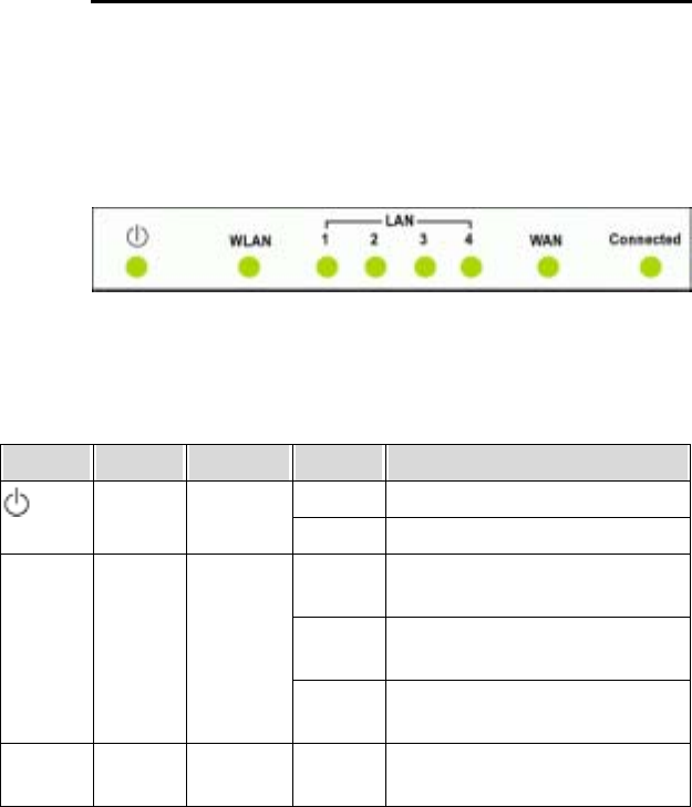
The following illustration shows the front panel of the Wireless
Broadband Router :
LED Indicators
The Wireless Broadband Router is equipped with eight LEDs on
the front panel as described in the table below (from left to right) :
LEDs Function Color Status Description
Off No power is supplied to the unit.
Power Green
Solid Power is connected to the unit.
Off WLAN interface is not initialized
properly.
On WLAN interface is initialized properly
and ready.
WLAN Wireless
Ready/
Activity
Green
Blinking Transmitting/receiving packets to/from
WLAN interface.
LAN 1-4 LAN port
Status
Green
(100 Mbps)
Off Power is off or no Ethernet device is
connected.
Wireless Broadband Router User Manual
6
LEDs Function Color Status Description
Slowly
blinking
Ethernet device is connected. Orange
(10 Mbps)
Quickly
blinking
Transmitting/receiving packets on the
LAN port.
Off Power is off or no broadband device
is connected.
Slowly
blinking
Broadband device is connected.
WAN WAN Port
Status
Green
Quickly
blinking
Transmitting/receiving packets on the
WAN port.
Off Indicates the WAN port does not yet
obtain an IP address.
Connected Green
On Indicates the WAN port successfully
obtains an IP address.
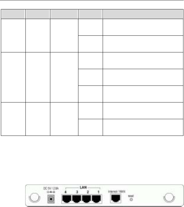
Rear Panel and Connectors
The following figure illustrates the rear panel of your Wireless
Broadband Router.
• DC 5V/2.8A: Power connector
• LAN Ports 1-4: RJ-45 Connectors. Integrated 4-port
10/100BaseT switch. Connects to a hub, switch or
NIC-equipped PC in your network. The LAN ports support
Auto-MDIX feature which eliminates the need for
crossover cables.
• Internet / WAN: RJ-45 connector. Connects to the
Cable/ADSL Modem. The WAN port also supports
Auto-MDIX feature which eliminates the need for
crossover cables.
• Reset button

2. Hardware Description & Installation
7
To reset the device to factory defaults, insert a
straightened paperclip into the Reset hole to press the
button. Keep pressing and power cycle (off and on) the
device. Wait for at least 5 seconds to release the button.
Then wait for the device to finish booting.
If you want to restore your customized settings after loading
defaults, refer to “4.8 Administration” for more information.
2.2 Hardware Connection
Choosing a Place for the Router
• Place the device close to the power outlet for the cable to
reach it easily.
• Avoid placing the device in places where people may walk
on the cables. Also keep it away from direct sunshine or
heat sources.
• Place the device on a flat and stable stand.
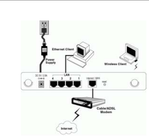
Connecting the Wireless Broadband Router
Prior to connecting the hardware, make sure to power off your
Ethernet device, Cable/ADSL modem and Wireless Broadband
Router. Then follow the steps below to connect the related devices.
Step 1 Connecting Your PC to the LAN port.
Attach one end of the Ethernet cable with RJ-45
connectors to your hub, switch or a PC’s Ethernet port,
and the other end to one of the LAN ports of your
Wireless Broadband Router.
Step 2 Connecting Cable/ADSL Modem to the Internet/WAN
port.
Connect the Ethernet cable attaching to your Cable/ADSL
modem to the Internet/WAN port of your Wireless
Broadband Router.
Step 3 Connecting the power adapter.

Wireless Broadband Router User Manual
8
Connect the single DC output connector of the power
adapter to the power jack on the back of the Wireless
Broadband Router. Then connect the supplied power cord
to the power adapter and the other end to an AC outlet.
Step 4 Turn on the power switch.
2. Hardware Description & Installation
9
The figure below illustrates a connection diagram example:

11
3 Setting Up Ethernet/WLAN Client
To access the Wireless Broadband Router via Ethernet or wireless
network, you must properly configure the network settings of your
Ethernet or wireless client PC. As the Wireless Broadband Router
is configured with the default IP address of 192.168.1.1 and
subnet mask of 255.255.255.0, and its DHCP server is enabled
by default, you can configure your PC’s TCP/IP settings as one of
the following:
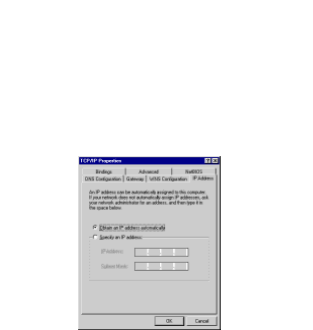
1. To use dynamic IP: Set your PC to be DHCP client to accept
the dynamic IP from the router.
2. To use static IP: Set the IP address as 192.168.1.x (x is
between 2 and 254), subnet mask as 255.255.255.0 and the
gateway as 192.168.1.1 to be on the same subnet with the
router.
This chapter describes how to configure your PC to be a DHCP
client for initial connection to the device. If you have modified the
router’s network setting, your LAN/WLAN clients should make
appropriate changes in order to make successful connection.
3.1 Setting up Ethernet Client
To access the Wireless Broadband Router via Ethernet, make sure
your PC is equipped with Ethernet network card and has
appropriate network card driver and TCP/IP installed.
Note:
1. If TCP/IP protocol is not installed on your PC, refer to Windows
documentations for installation instructions.
2. For initial verification, we suggest that you connect only one PC
directly to an Ethernet port on the Wireless Broadband Router, not
through a hub.
Wireless Broadband Router User Manual
12
For Windows 98/ME
Step 1 Click on the Start menu, point to Settings and click on
Control Panel.
Step 2 Double-click the Network icon.
Step 3 In the Network window, highlight TCP/IP protocol for your
NIC and click Properties.
Step 4 On the IP Address tab, select Obtain an IP address
automatically. Then click OK.
Step 5 If your network settings is changed, you will be prompted
with System Settings Change dialog box, click Yes to
restart your computer.
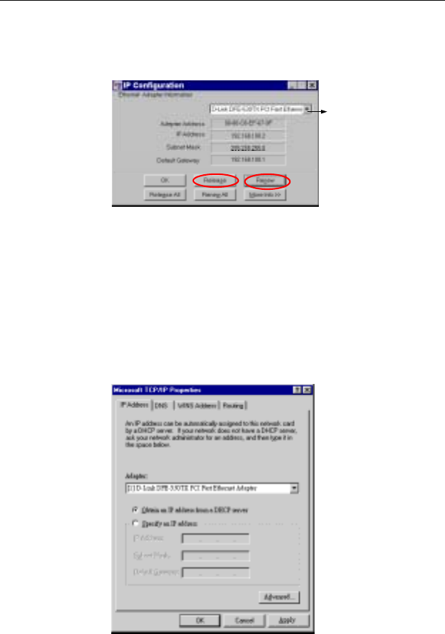
Checking/Renew IP Address under Windows 98/ME
The following steps help you verify if your network adapter gets an
IP address within the DHCP IP pool range (192.168.1.100 ~
192.168.1.150 by default) of the router. If not, you may need to
renew the IP information.
Step 1 From the Start menu, click Run to open the Run dialog
box.
Step 2 Enter winipcfg in the dialog box and then click OK.
3. Setting Up Ethernet/WLAN Client
13
Step 3 Select the Ethernet or WLAN adapter from the drop-down
list to show the IP address. If necessary, click Release
and then Renew to get a new IP address.
Click the drop-down
arrow to select your
Ethernet adapter.
For Windows NT
Step 1 Click Start, point to Settings, and then click Control
Panel.
Step 2 Double-click the Network icon.
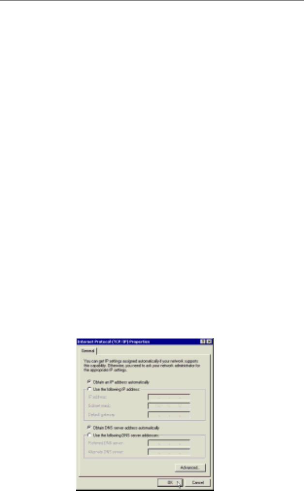
Step 3 On the IP Address tab, click on the drop-down arrow of
Adapter to select required adapter. Enable Obtain an IP
address from a DHCP server and then click OK.
Step 4 When returning to Network window, click Close.
Step 5 When prompted with Network Settings Change dialog
box, click Yes to restart your computer.
Wireless Broadband Router User Manual
14
Checking/Renew IP Address under Windows NT
The following steps help you verify if your network adapter gets an
IP address within the DHCP IP pool range (192.168.1.100 ~
192.168.1.150 by default) of the router. If not, you may need to
renew the IP information.
Step 1 Click Run from the Start menu to open the Run dialog
box.
Step 2 Type cmd in the dialog box and then click OK.
Step 3 At prompt, type ipconfig to see the IP information from
DHCP server.
Step 4 If you want to get a new IP address, type ipconfig
/release to release the previous IP address and then type
ipconfig /renew to get a new one.
For Windows 2000
Step 1 From the Start menu, point to Settings and then click
Network and Dial-up Connections.
Step 2 Right-click the Local Area Connection icon and then
click Properties.
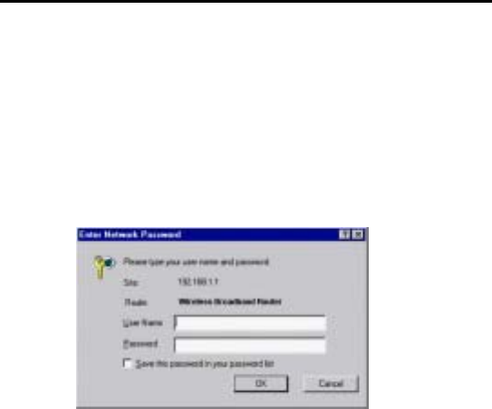
Step 3 On the General tab, highlight Internet Protocol (TCP/IP)
and then click Properties.
Step 4 Enable Obtain an IP address automatically and then
click OK.

3. Setting Up Ethernet/WLAN Client
15
Checking/Renew IP Address under Windows 2000
To verify if your network adapter gets an IP address within the
DHCP IP pool range (192.168.1.100 ~ 192.168.1.150 by default) of
the router, follow the related description under Windows NT section.
The procedures are the same.
3.2 Setting up Wireless Client
You can also choose to access the router via a wireless client,
whether for configuration purpose or sharing network resource and
Internet connection. To get your wireless client connected to the
router, verify the following:
1. Make sure your PC is equipped with WLAN adapter and has
appropriate WLAN card driver/utility and TCP/IP installed.
2. Set the WLAN client to obtain a dynamic IP address from the
Wireless Broadband Router.
The procedures are the same as described above. The only
difference is that you are configuring the TCP/IP associated
with your Wireless LAN Card.
3. Verify that your WLAN setting is identical to the router’s default
wireless settings:
• Operation Mode: Infrastructure
• SSID: Refer the default SSID of the device
• Authentication: Open
• WEP Mode: Disabled

Wireless Broadband Router User Manual
16
3.3 Checking Connection with the Router
You can use the Ping command to verify whether or not your
Ethernet/Wireless client has successfully connected to the
Wireless Broadband Router.
To execute ping command, open the DOS window and ping the IP
address of the router at the DOS prompt. For example:
ping 192.168.1.1
If the following response occurs:
Reply from 192.168.1.1 bytes=32 time=100ms TTL=253
Then the connection between the Wireless Broadband Router and
the network has been successfully established.
Otherwise, if you get a failed ping with the response of:
Request time out
Then the connection is fail. Verify your network setting is correct.
For Ethernet client, also check the cable between the router and
the PC.
17
4 Web Configuration
4.1 Accessing Web-Based Configuration Utility
Once your PC is properly configured as described in "3. Setting Up
Ethernet/WLAN Client", you can proceed as follows for initial
configuration:
1. Start your Web browser and type http://192.168.1.1 in the
URL field. This address is the default private IP of your router.
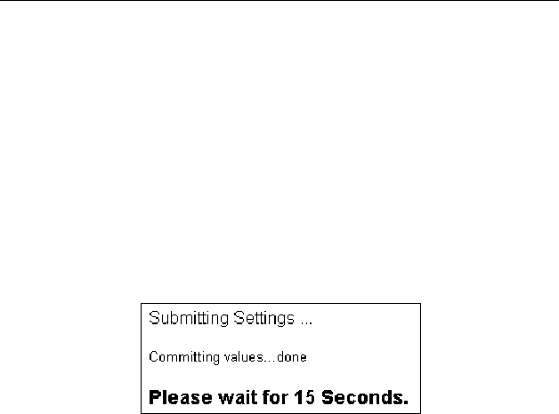
2. After connecting to the device, you will be prompted to enter
the username and password. Leave the username empty and
enter the default password of admin.
Figure 4-1 Login to Web Configuration Utility
After you login, the System Overview page of the Wireless
Broadband Router displays. From now on the Wireless Broadband
Router acts as a Web server sending HTML pages/forms on your
request. You can click the menu options at the top to start your
configuration task.
While working with this Web Configuration Utility, corresponding
configuration fields are displayed according to your specific
selection to avoid any possible conflicting setting. In addition,
should you input invalid values, the utility provides instant prompt
to help you recover from error inputs.
Wireless Broadband Router User Manual
18
To enable Your Settings
After you have customized the settings and then click the Apply
button, the device will begin registering your settings. You will be
prompted to wait for a few seconds for the router to commit
changes to permanent storage. During this process, it is important
not to switch on or off the router otherwise damage may be caused
to the device.
After the settings have been registered, the screen will return to
previous page and the settings are effective. You may then
proceed with other configuration tasks.
Figure 4-2 Apply Changes
4. Web Configuration
19
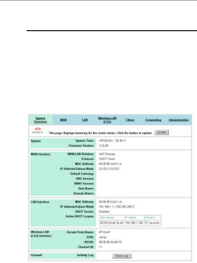
4.2 Viewing System Status
Clicking System Overview in the menu bar will display the
System Overview page which shows the basic information of your
Wireless Broadband Router, including the system, WAN/LAN
interface and Wireless LAN interface information. You may click
the Update button to update the overall status.
If firewall is enabled, an additional item Firewall is displayed at the
bottom of the page. Clicking the Show Log button under this item
will display the firewall activity log in a separate window.
Figure 4-3 System Overview

Wireless Broadband Router User Manual
20
4.3 Configuration for NAT Routing Mode
Prior to configuring your Wireless Broadband Router, you must
decide whether to configure the device as a router or as a bridge.
This section only describes how to set up the device to act as a
router. For bridge configuration, see ”4.4 Configuration for Bridge
Mode” for instructions.
When operating as a router, the device communicates with your
ISP through the WAN port. Depending on the connection type
offered by your ISP, you may get the WAN IP address by one of
the following means:
• DHCP Client: In this connection type, your router acts as
a DHCP client and requests IP information from the DHCP
server on the ISP side. Select this option if your ISP
assigns you with a dynamic IP address each time you log
on.
• PPPoE Client: Some ISPs use a PPPoE session to make
connection with their clients. If this is the case, you should
enable this option and finish the PPPoE Client settings.
The WAN port of the device will be assigned a public IP
address from your ISP’s server.
• PPTP Client: This router supports VPN (Virtual Private
Network) pass-through for both PPTP (Point-to-Point
Tunneling Protocol) and IPSec (IP Security). VPN allows
corporations to extend their own corporate network
through private "tunnels" over the public Internet.
Effectively, a corporation uses a wide-area network
as a single large local area network. A company no
longer needs to lease its own lines for wide-area
communication but can securely use the public
networks.
• Manual Config: If your ISP assigns you a fixed IP
address, you should select this option and manually enter
the IP information provided by your ISP.
Different configuration items will be displayed depending on your
connection type. Consult with your ISP which option applies to you

4. Web Configuration
21
and obtain related information for correct configuration. Then
proceed to finish the following procedures.

Wireless Broadband Router User Manual
22
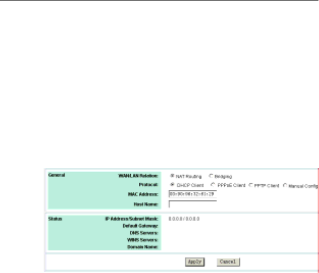
WAN Configuration for NAT Routing Mode
Click WAN in the configuration menu to enter the WAN
configuration page and carry out the procedures below.
Part 1. Configuring general settings.
1. In the WAN/LAN Relation item, select the NAT Routing
option.
This option allows the device to act as a router and use the
built-in NAT function to translate your multiple private IP
addresses to a single public IP address. However, only
outgoing requests are allowed to pass through the device
unless you specify otherwise. Outside users cannot see your
private local IP addresses. This leaves your home or business
network hidden from outside intruders.
2. In the Protocol item, select a protocol type according to the
connection type offered by your ISP.
3. If required, in the MAC Address field, enter your network
adapter’s MAC address in the format of xx:xx:xx:xx:xx:xx.
Otherwise just keep the default values.
This field allows you to clone a network adapter’s MAC
address to the WAN port of the router. Some ISPs use the
MAC address of NIC, which was connected to your
Cable/ADSL modem, for static mapping and thus give you the
same IP address each time the Cable/ADSL modem requests
for IP address for the Ethernet port. If this is the case, this
feature removes the need of asking your ISP to change the
registered MAC address and you can still use the same given
IP for the router’s WAN port.
4. In the Host Name field, you may supply a host name for this
router if this is required by your ISP. Some ISPs only respond
to a DHCP request with a valid “Host Name”. If a host name is
not necessary for your ISP, just leave it blank.
4. Web Configuration
23
Part 2. Configuring protocol settings
According to the connection type you selected above, proceed to
set up related parameters.
υ DHCP Client
If DHCP Client is your option, no other configuration is needed.
You may just click Apply to end your WAN settings. After the
connection to your ISP is established, the information provided by
your ISP will be displayed in the Status group.
Figure 4-4 WAN Configuration-DHCP Client
υ PPPoE Client
If PPPoE Client is your option, configure these fields as required by
your ISP.
PPPoE Connection Status: This item is not configurable. It
displays whether the connection is up or down.
Username/Password: Enter the username and password
provided by your ISP used to log on to Internet connection.
Connection Mode: Select your PPP connection from these
options:
Keep Alive: This feature will keep your PPPoE-enabled
Internet connection always alive. This is done by sending echo
requests periodically to ISP to prevent the connection from
being terminated by ISP.
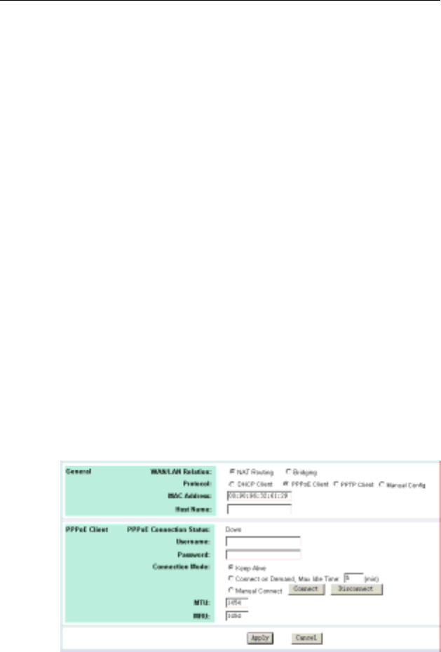
Wireless Broadband Router User Manual
24
Connect on Demand: If enabled, the router will trigger a PPP
session for connection to the Internet if any client PC on your
LAN sends out a request for Internet access. However, the
router automatically disconnects the PPP session after the
WAN connection has been idle for the amount of time you
specified in the Max Idle Time box. If your Internet account is
billed based on the amount of time of your Internet connection,
you probably want to enable this option and enter an idle time
value best suitable for your network.
Manual Connect: If enabled, the system administrator can
manually connect or disconnect the PPP session by clicking
the Connect/Disconnect buttons in this page.
MTU/MRU: Allows you to adjust the Maximum
Transmission/Receive Unit in bytes for the WAN interface. You
may need to adjust the values to a smaller size if the servers of
your ISP do not support full size frame packets. The packets larger
than the specified values will be fragmented and the performance
may therefore be influenced.
It’s suggested not to modify the MTU/MRU settings unless
instructed by your ISP.
After you finish the WAN settings, click Apply to submit your
changes.
Figure 4-5 WAN Configuration-PPPoE Client
4. Web Configuration
25
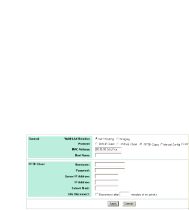
υ PPTP Client
If PPTP Client is your option, configure these fields as required.
Username/Password: Enter the access credentials, i.e.,
username and password, for the router to initiate a PPTP
connection to the PPTP server.
Server IP Address: Enter the IP address of the PPTP server.
IP Address/Subnet Mask: Enter the Internet IP address/subnet
mask that the ISP assigns to this router for reaching the PPTP
server.
Idle Disconnect: If checked, enter the amount of time the
router will maintain the PPTP connection to when there is no
traffic.
Figure 4-6 WAN Configuration-PPTP Client
Wireless Broadband Router User Manual
26
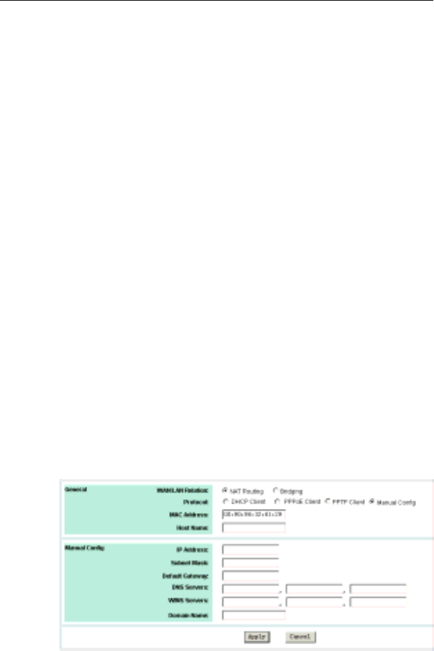
υ Manual Conifg
If Manual Config is your option, configure these fields as required
by your ISP.
IP Address/Subnet Mask: Enter the fixed IP address and subnet
mask given by your ISP in respective fields. The default values are
0.0.0.0/0.0.0.0.
Default Gateway: The IP address of the default gateway of the
router. It is the IP that the router first contact to communicate with
the Internet. The default is 0.0.0.0.
DNS Servers: Specifies the IP address of the Domain Name
Server. Your LAN side DHCP clients use the DNS to map a
domain name to its corresponding IP address and vice versa. Up to
three DNS servers are allowed. If no DNS server is specified or the
specified servers are not available, the router will automatically
assign a DNS server to the DHCP clients.
WINS Servers: Optional for Windows Internet Names Service.
Enter the IP addresses of WINS servers if required.
Host Name & Domain Name: Optional. Allows you to supply host
and domain name for the router.
After you finish the WAN settings, click Apply to submit your
changes.
Figure 4-7 WAN Configuration-Manual Config

4. Web Configuration
27
LAN Configuration for NAT Routing Mode
Your router communicates with your LAN through its LAN port. The
LAN configuration page allows you to define the private IP address
and DHCP server settings over the LAN interface.
1. In Manual Config > IP Address & Subnet Mask field, enter
the IP address and subnet mask for the LAN port.
By default, the IP address and subnet mask of the LAN port is
192.168.1.1 and 255.255.255.0 respectively. Note that if you
change the private IP address and apply the changes, the PC
from which you configure the router will lose the
communication to the router. To reconnect, you will need to
renew the IP address of the PC or change to an IP address
compatible with the new LAN port IP address.
2. In DHCP Server > Service field, select whether to enable
DHPC service on the LAN port.
The Wireless Broadband Router implements a built-in DHCP
(Dynamic Host Configuration Protocol) server on its LAN
interface, which dynamically assigns IP addresses to the
DHCP clients on the LAN/WLAN. The DHCP server also
provides a default gateway (the router’s LAN IP address) and
DNS addresses for DHCP clients to access the Internet.
DHCP function spares you the hassle of manually assigning a
fixed IP address to each PC on the LAN/WLAN. It is probably
you already have a DHCP server on your network and you do
not enable this function. DHCP server is enabled by default.
Note: It is not allowed to have two DHCP servers running on
one LAN at the same time. If you decide to enable the DHCP
on this router, remember to disable the DHCP function of the
other device.
If you disable DHCP server, just click Apply to submit your
changes. Otherwise proceed to next step.
3. If DHCP server is enabled, enter the fields below:
DHCP Lease Time: Specify the time that a network device
can lease a private IP address before the DHCP server
reassigning the IP address.
IP Pool Range: Specify the starting and ending IP address of
the IP address pool. Whenever a network device requests an
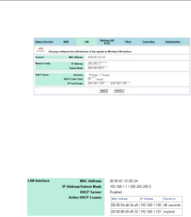
Wireless Broadband Router User Manual
28
Internet session, the router will allocate an unused IP address
from this pool and lease them to the device for a specified
amount of time.
Figure 4-8 LAN Configuration in Router Mode
Viewing Current DHCP Assignments
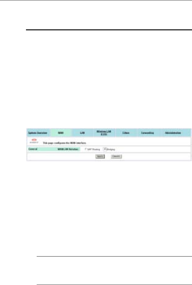
When DHCP server function is enabled for your LAN, the router
keeps a record of any machine (either Ethernet or Wireless node)
that has leased IP from the specified IP pool. The DHCP lease
table is displayed under System Overview > LAN Interface:
Figure 4-9 DHCP Lease Table
4. Web Configuration
29
4.4 Configuration for Bridge Mode
A bridge connects two or more LANs together and bases the
forwarding decision on the MAC address. Under Bridge mode,
filters and forwarding are not applicable. Acting as a bridge, the
devices supports DHCP server service. To set up the bridge mode,
perform the procedures below.
Part 1. Enable bridging function.
Go to the WAN configuration page and select the Bridging option
as the WAN/LAN relation and then click Apply to commit the
changes.
Figure 4-10 Enabling Bridging
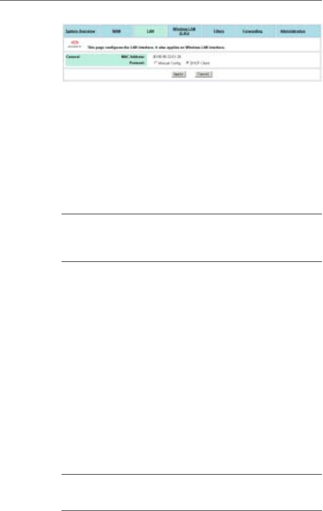
Part 2. LAN configuration.
1. In the Protocol item, select DHCP Client or Manual Config
as required.
DHCP Client: Select this option if there is already a DHCP
server in your network which assigns IP to this bridge. If
enabled, no further configuration is needed since the DHCP
server will pass the required IP information. Click Apply to
submit your changes.
Note: After committing the settings, your configuring PC may
lose connection to the device. To reconnect, you will need to
make sure the PC uses an IP address in the same subnet as
the device.
Wireless Broadband Router User Manual
30
Figure 4-11 Bridge Mode-DHCP Client
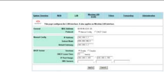
Manual Config: If enabled, manually enter the IP address and
its subnet mask in IP Address & Subnet Mask fields.
2. For Manual Config setting only, in DHCP Server > Service
item, select whether to have your bridge act as a DHCP
server.
If you disable DHCP service, no further configuration is
required. Just Apply to submit your changes.
Note: After committing this setting, your configuring PC may
lose connection to the device. To reconnect, you will need to
make sure the PC uses an IP address in the same subnet as
the manually entered IP.
If DHCP server service is enabled, proceed to set up the items
below:
DHCP Lease Time: Specify the time that a network device
can lease a private IP address before the device reassigning
the IP address.
IP Pool Range: Specify the starting and ending IP address of
the IP address pool. Whenever a network device requests an
Internet session, the device will allocate an unused IP
addresses from this pool and lease them to the device for a
specified amount of time.
Default Gateway & DNS Servers: Specify the default gateway
and DNS servers for your network. These settings allow your
network to access the Internet
After finishing the settings above, click Apply to submit the
changes.
Note: Under Manual Config setting, after DHCP Server takes
effect, your configuring PC will need to renew its IP address to
connect to the device.
4. Web Configuration
31
Figure 4-12 Bridge Mode-Manual Config

Wireless Broadband Router User Manual
32
4.5 Wireless LAN (2.4G) Configuration
The Wireless Broadband Router implements Access Point
capability which connects wireless clients to a wired LAN. It allows
wireless nodes to access network resources and share the
broadband Internet connection. With the default values, the router
(Access Point) can be easily associated by a wireless client. We
suggest that you customize the wireless settings to prevent
unauthorized association.
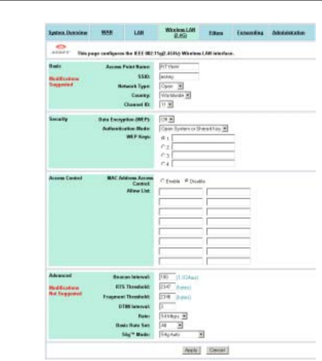
υ Basic Configuration
Access Point Name: The name used for identifying the Access
Point.
SSID: Service Set ID. It uniquely identifies a logical network
domain name of your WLAN. The default value is IEEE 802.11
LAN.
Network Type: An “Open” AP will periodically broadcast its SSID
to allow the wireless clients to recognize their presence. However,
this creates a security hole since any wireless station with SSID set
to “any” or got the broadcast may associate to your AP. It is
recommended to set this option to Closed to have your AP only
accept stations whose SSID are the same as this AP.
Country: Select the country where you use this AP. When the
country setting is changed, the AP scans only the legal frequency
channels allowed in that regulatory domain.
Channel ID: The radio frequency used for communication.
Available channels vary according to the regulations in the country
you specified in the Country drop-down list. Select a channel out
of the available cannels or use the default channel.
υ Security
Data Encryption (WEP Mode): WEP (Wired Equivalent Privacy) is
an authentication algorithm which encrypts your data and protects
your Wireless LAN against eavesdropping.

4. Web Configuration
33
WEP is disabled by default. If you want to protect your data when it
is transferred from one station to another, you should enable this
security option. For security concern, we strongly suggest you
enable WEP function.
To enable WEP, select 64 bits or 128 bits option as the encryption
algorithm. The higher the bit number, the greater the complexity
and the security of the encryption.
Authentication Mode: Authentication is a process in which the AP
validates if wireless clients are qualified to access the AP’s service.
This happens prior to any wireless client can associate to an AP.
The IEEE 802.11b defines two types of algorithms in authentication:
the “Open System” and “Shared Key”.
With Open System, the authentication is done through a pseudo
process, accepting all kinds of requests, mainly used in cases
where connectivity is more important than security. Shared Key,
on the other hand, utilizes WEP capability to further verify if the
wireless client is authorized to share this AP’s resource. If the client
has the wrong key or no key, it will fail authentication and will not
be allowed to associate with the AP.
If you select Open System or Shared Key, wireless stations can
communicate with or without data encryption.
WEP Keys: Enter one to four WEP keys in either ASCII or
Hexidecimal format. Note that when using Hexidecimal format, only
digits 0-9 and letters A-F, a-f are allowed. Valid key length for each
encryption type is as below:
HEX Format ASCII Format
64 Bit 10 hexadecimal digits 5 ASCII characters
128 Bit 26 hexadecimal digits 13 ASCII characters
Aside from entering your WEP keys, you should select one of the
four keys to encrypt the data before being transmitted. The AP
always transmits data encrypted using this WEP Key. The key
number (1,2,3,4) is also transmitted. The receiving station will use
the key number to determine which key to use for decryption. If the
key value does not match with the transmitting station, the

Wireless Broadband Router User Manual
34
decryption will fail. To ensure successful decryption, have your
wireless stations set identical key tables.
Note: All Wireless Stations must use identical encryption algorithm
level and Key values (same key position in its key table) to ensure
successful data transmission.
υ Access Control
MAC Address Access Control: The device also supports
authentication based on the MAC address of a wireless client. If
this function is enabled, the AP will allow association by a client
only if that client's MAC address matches an address in the Allow
List.
To enable this function, select the Enable option and then
manually key in MAC address in the Allow List. Up to 16 MAC
entries are allowed.
υ Advanced Configuration
We suggest you not to modify the Advanced parameters unless
specific requirement is required. The parameters are described as
below:
Beacon Interval: Defines the periodic interval at which the 802.11
WLAN Access Point sends out a beacon.
RTS Threshold: Request to send threshold. It specifies the packet
size beyond which the AP invokes its RTS/CTS mechanism.
Packets that exceed the specified RTS threshold trigger the
RTS/CTS mechanism.
Fragment Threshold: It determines whether packets will be
fragmented and at what size. On an 802.11 wireless LAN, packets
exceed the fragmentation threshold are fragmented, i.e., split into,
smaller units suitable for the circuit size. On the other hand,
packets smaller than the specified fragmentation threshold value
are not fragmented.
DTIM: Specifies the Deferred Traffic Indicator Map (DTIM) period.
This value determines at which interval the AP will send the next

4. Web Configuration
35
DTIM when the AP has buffered broadcast or multicast messages
for associated clients. Its clients hear the beacons and awaken to
receive the broadcast and multicast messages. The default value
is 3.
Rate: Sets the rate of data transmission according to the speed of
your wireless network. You can select from a range of transmission
speeds (from 1 to 54 Mbps) or keep the default setting, Auto, to
have the AP automatically use the fastest possible data rate and
enable the auto-fallback feature.
Basic Rate Set: Sets what data rate control and management
frames will be transmitted at. The Default option uses 1 or 2 Mbps
for 802.11b and 6, 12 or 24Mbps for 802.11g. The All option uses
1, 2, 5.5, 6, 11, 12, 18, 24, 36, 48, or 54Mbps.
54g Mode: Allows you to choose the 54g mode between 54g
Auto, 54g Performance and 802.11b Only.
Wireless Broadband Router User Manual
36
Figure 4-13 Wireless LAN Configuration

4. Web Configuration
37
4.6 Filters
When your Wireless Broadband Router operates as a router, the
built-in NAT function provides your LAN with the Internet access
via the single public IP of the WAN port. That means all network
devices are allowed to access various Internet service. Under this
circumstance, network security becomes an important issue and
system administrators may need to build access control to protect
the network.
The filter feature serves as a basic firewall security measure for
your network. When filter function is enabled, the Wireless
Broadband Router inspects all data packets arrive from LAN side
and determines if packets are allowed to pass through the WAN
port depending on whether packets match your filter rules and
whether your filter type is Listed Pass or Listed Block.
In addition to filter settings, the Filters page also allows to configure
other firewall settings, including WAN Management, WAN Port
Ping Reply and Report Log to TFTP Server.
Specifing Your IP Filter Rules
If you are going to specify your filter rules, follow the procedures
below:
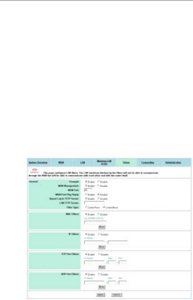
1. In the Firewall item, select the Enable option.
2. In the Filter Type item, select the action (Listed Pass or
Listed Block) to be performed on the IP packets matching
your filter rules.
2. In the four filter types, select whether to enable or disable each
filter.
3. If a filter is enabled, enter the criteria in provided fields. Click
More to add more criteria if required. See next section for
more information.
4. Click Apply to commit your changes.

Wireless Broadband Router User Manual
38
Filter Types
When setting up filter rules, you can define the Filter rules based
on the LAN machine’s MAC address, IP address or the protocol
type of the data packet. Each filter type is described as below.
Note: Based on OSI reference model, MAC Filters demand higher
priority than IP Filters while IP Filters higher than Port Filters.
MAC Filters: The MAC address of the LAN machine from which
packets are allowed (or prohibited) to pass through the WAN port.
Up to 12 entries are allowed.
IP Filters: The range of IP addresses of the LAN machines from
which packets are allowed (or prohibited) to pass through the WAN
port. You may enter the same address in both (Start and End)
fields to define a single IP address. Up to 5 entries are allowed.
TCP Port Filters: Allows (or prohibits) certain LAN machine to use
TCP based service in the specified port range through the WAN
port. Up to 12 entries are allowed.
For example, to allow (or prohibit) local PC 192.168.1.210 to use
FTP service (using TCP port 21):
IP Address Start End
192.168.1.210 20 21
UDP Port Filters: This field allows you to allow (or prohibit) certain
LAN machine to use UDP based service in the specified port range
through the WAN port. Up to 12 entries are allowed.
For example, to allow (or prohibit) local PC 192.168.1.210 to use
ping service (using UDP port 53):
IP Address Start End
192.168.1.210 53 53
4. Web Configuration
39
Filter Scenario of the Wireles Broadband Router
When setting up your firewall policy, note the filter scenario used
by the router:
When Filter Type is Listed Block:
If all the filters are disabled: No filter rule is specified to
block any packet. All packets can pass through the WAN
port. (Defaults)
If any filter is enabled: only the packets matching the
specified rule are blocked; other packets can pass through
the WAN port.
When Filter Type is Listed Pass:
If all the filters are disabled: No filter rule is specified to
allow any packet to pass. All packets are blocked.
If any filter is enabled: Only the packets matching the
specified rule can pass; other packets are blocked.
Figure 4-14 Filters
Wireless Broadband Router User Manual
40
Viewing Filter Log
When filter feature is enabled, the router will keep a record of the
packets discarded. To view the firewall activity log, go to System
Overview > Firewall > Activity Log and click the Show Log
button. Filter activity log is displayed in a separate window with a
maximum of 32 entries. Clicking the Update button allows to
refresh the log with newly reported data. The log types are defined
as below:
Type Description
1 Blocked packets, from WAN side, by DoS (Deny of Service)
protection mechanism.
2 Blocked packets, from LAN side, by MAC/IP/TCP/UDP filter.
Other Firewall Settings
WAN Management: Available only when Firewall is enabled. If
available, this item is disabled by default that rejects any external
access from the WAN port. If this option is enabled, a WAN Port
filed is displayed with the default value 80. If required, you may
enter another port number used by the external WAN access.
If WAN Management is enabled using a non-80 port, the router’s
HTTP service (Web Configuration Utility) will be accessible via the
router’s WAN port IP address following by a colon and the non-80
port:
http://<WAN IP address>:<non-80 port>
For example, if 1234 is entered, the router will be accessible at
http://203.1.2.3:1234 where 203.1.2.3 indicates the WAN port’s IP
address.
If WAN Management is enabled using standard port 80, no suffix is
required.
If WAN Management is enabled using port 80, your publicly
accessible Web server (if any) on LAN side should use a non-80

4. Web Configuration
41
HTTP port. And you need to use the Forwarding feature to shift
external HTTP requests to the non-80 port number used by the
Web server on LAN side.
WAN Port Ping Reply: Available only when Firewall is enabled. If
available, this setting determines if an external host will get reply
when trying to ping the IP address of your WAN port. It’s disabled
by default.
Report Log to TFTP Server: Available only when Firewall is
enabled. If available, it specifies whether to report firewall event log
to your TFTP server. If enabled, a LAN TFTP Server field is
present for you to specify the IP address of the TFTP server. All
the filter logs are sent to TFTP server although only 32 entries are
displayed in Show Log window (see System Overview page).

Wireless Broadband Router User Manual
42
4.7 Forwarding
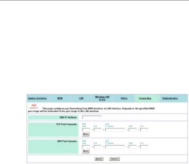
This page allows you to configure the Forwarding and DMZ
(De-Militarized Zone) features. Unlike Filter which governs
outgoing traffic, Forwarding is used to provide external access to
your local machines. This is commonly used when you have
publicly accessible virtual servers on your local network.
By default, forwarding entry is empty and any external access to
your LAN is blocked. Once you define a forwarding entry, incoming
packets (identified by its port number) that match your Forwarding
criteria will be forwarded to the port range of the specified local
machine. Otherwise packets are blocked. Forwarding serves as a
measure of security that protect your network from hazardous
packets.
However, if you designate a DMZ sever, incoming packets that do
not match the forwarding criteria will be redirected to the DMZ IP
address. That is, forwarding demands a higher priority than DMZ.
Setting Up Forwarding Entries
To set up your forwarding entries, enter these fields:
DMZ IP Address: DMZ setting allows a local machine to be
exposed to the Internet. If you specify a DMZ host here, all virtual
services requests not specified in the Forwarding table are
forwarded to the DMZ host.
TCP Port Forwards: In the first Start and End fields, define the
port range for the incoming TCP service you want to forward. In the
IP Address filed, enter the IP address of the virtual server to which
packets are forwarded. The Start/End fields on right side defines
the port range for the TCP service on the virtual server.
For example, you have a virtual server 192.168.1.210 running FTP
service and you allow external access by the setting below:

4. Web Configuration
43
Start End IP Address Start End
20 21 192.168.1.210 20 21
UDP Port Forwards: The configuration is the same as setting TCP
Port Forwards, only that the entry applies to UDP service.
When the router gets outside TCP/UDP requests destined for the
WAN port, it determines whether the services are allowed
according to your forwarding settings. For example, if you do not
specify FTP virtual service in Forwarding table, incoming FTP
requests (identified by port number in packets) are blocked or
otherwise sent to DMZ host (if specified). On the other hand, if an
FTP forwarding entry has been set up, the FTP requests will be
able to be forwarded to the specified machine.
If you have a Web server on your network…
If you enable WAN Management (i.e., allow external access from
the WAN port, see “4.6 Filters” ) and want to designate another
Web server on your local network, take either of the procedures
below to avoid port confliction:
Option 1: In Filters page, with WAN Management enabled, enter
a port number other than 80 (for example, 1234) and reserve the
number 80 for your Web server.
If any external host wants to access your Web management server
through the WAN port, it should use the address below:
http://204.71.200.143 (i.e., the WAN IP address):1234
Option 2: Have WAN Management to use the standard port
number 80 and your Web server (e.g., 192.168.1.4) to use another
port number (e.g., 8080). In this case, you need to shift the
incoming HTTP request (destined for local Web server) to port
8080 of your Web server, the forwarding entry may look like this:
Start End IP Address Start End
8080 8080 192.168.1.4 8080 8080
Wireless Broadband Router User Manual
44
With the settings above, an external host trying to access your
local Web server should use the address like this:
http://204.71.200.143 (i.e., the WAN IP address):8080
If you do not enter the suffix “:8080”, the external host’s packets
will contain the standard port number 80 and the router will not
forward the packets since no forwarding entry matches. As a result,
if a WAN computer tries to access the LAN’s Web server, it will turn
to access the Web service on the WAN port, i.e., the Web
Configuration Utility of the router instead.
Figure 4-15 Forwarding

4. Web Configuration
45
4.8 Administration
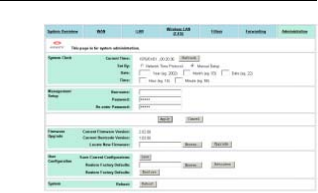
υ System Clock Configuration
Network administrators may want to synchronize date and time
among network devices. This can be done by synchronizing the
local clock to an available NTP server or manually specifying the
date and time in this router for your network.
Option 1: Using an existing NTP server.
1. In Set by item, enable the Network Time Protocol option.
2. In NTP Server field, enter the IP address of the NTP server.
3. In Update Interval item, select your update interval as 1, 2 or
7 days.
4. In Time Zone field, select a time zone according your
geographic location.
Option 2: Specifying the router as your network NTP server.
1. In Set by item, enable the Manual Setup option.
2. Manually enter the date and time information in respective
fields.
υ Management Setup
Username&Password: For administration security, specify
required User Name and Password and re-enter password in
corresponding field for confirmation. This setting limits your
Web-based manager access to users with the correct credentials.
By default, the user name is empty and the password is admin.
υ Firmware Upgrade
This option allows you to upgrade the Wireless Broadband Router
with new firmware. After upgrading, your customized configuration
will still exist and not reset to the factory defaults. To upgrade,
download required firmware file to your host PC and follow the
steps below:

Wireless Broadband Router User Manual
46
1. In the Locate New Firmware field, click Browse to locate the
firmware file.
2. Click the Upgrade button to start upgrade and then wait for a
few minutes as the utility prompts. You will return to the
Administration page while the process is complete.
Note: Do not interrupt the upgrade process otherwise it might
cause damage to your Wireless Broadband Router.
After upgrade, you can see the new firmware version in Current
Firmware version field.
υ User Configurations
Save Current Configurations: Allows you to save your
customized settings to the device. Once your router is properly
configured, you may wish to save current settings. The saved
settings can be retrieved easily if required, even after you reload
factory defaults.
Retrieve User Configurations: If you have loaded factory defaults
(either via the Load Default button on the back panel or via the
Restore button in this group), you can restore your settings by
clicking the Retrieve button.
Restore Factory Defaults: To restore factory defaults, click the
Restore button and then wait for a few minutes as the utility
prompts. You will return to the Administration page while the
process is complete. This feature is basically the same as resetting
via the Load Default button (see “Rear Panel and Connectors”) on
the device but it allows you to remotely perform the reset task.
υ System
Reboot: This option allows to you remotely reboot the device.
4. Web Configuration
47
Figure 4-16 Administration

49
5 Specification
5.1 Hardware
• 125MHz MIPS CPU
• 16MB SDRAM
• 4MB Flash Memory
• 802.11g: Broadcom (BCM4306, BCM2050)
• Two external antennas for wireless technology
Interface
• One 10/100 Base-TX RJ-45 auto sensing and crossover
Ethernet WAN port for Broadband connection (Cable/DSL
or direct Ethernet)
• Four RJ-45 LAN ports for 10/100Base-TX auto sensing &
crossover Ethernet Switch LAN connection
• 802.11g wireless LAN
• Two external antennas for wireless technology
Physical
• Front Panel: 8 LEDs ( Power x 1, LAN x 4, WAN x 1,
Wireless x 1, Connected x 1)
• Back Panel: Reset button, Power Jack, RJ-45 LAN Port x
4, RJ-45 WAN Port x 1
• Dimensions: 145 mm(L) x 240 mm(W) x 40 mm(H)
• Case types: Lay down
Power Adapter and Environmental Requirement
• DC Adaptor: Input AC100V – 240V , Output 5V DC, 2A
• Temperature: 0 to 40°C (operation), -20 to 70 °C (storage)
• Relative Humidity: 5% to 90% (non-condensing)

Wireless Broadband Router User Manual
50
Electromagnetic Compliance
• FCC Part 15 Class B
• CE
• EMI/Immunity: VCCI class B
• PTT: JATE
• Wi-Fi for 802.11b
5.2 Software
WAN Port Features
• PPPoE (PPP over Ethernet) Client with Keep
Alive/Connect On Demand Support
• PAP and CHAP Authentication
• DHCP Client
• MAC Address Cloning
• Settable and Changeable IP Address
LAN Port Features
• DHCP Server
• Settable and Changeable IP Address
Router Features
• NAT
• Firewall Support
• Bridge Mode Support
• 802.1D Spanning Tree Bridging
• IP Filtering, IP Forwarding
• DMZ Hosting
• DNS Forwarding
• UPNP Support
• Microsoft NetMeeting Passthrough Support
• Microsoft XP Messenger Passthrough Support

5. Specification
51
Security Features
• PAP and CHAP Authentication
• ASCII/HEX Format 64/128 Bit WEP Key for Wireless LAN
• Allow List for Wireless LAN
• Supports IP packets filtering based on IP address, port
number, and protocol
• VPN Support (IPSec Passthrough, and PPTP
Passthrough)
Wireless LAN Features
• Fully compatible to 802.11g standard
• Direct Sequence Spread Spectrum (DSSS) technology
exploitation
• Seamless roaming within wireless LAN infrastructure
• Low power consumption via efficient power management
Configuration and Management Features
• Configurable through Web Browser via WAN/LAN
• Software Upgrade
• DHCP Server function for IP distribution to local network
users
• NTP/Manual System Clock
• Configuration Saving/Retrieving
• Event Log