Askey Computer WLL6190D25 802.11g / 802.11n WLAN PCI-E Mini Card User Manual UserMan H8N WLL6190D25 rev
Askey Computer Corp 802.11g / 802.11n WLAN PCI-E Mini Card UserMan H8N WLL6190D25 rev
UserMan_H8N-WLL6190D25_rev

Introduction: Askey WLL6190D25
802.11g / 802.11n WLAN PCI-E Mini Card User's Guide
Before you begin
Things you should know
WLL6190D25 network
Before you begin
Obtain the following information from your network administrator (if you are a home user, obtain this information from the person that
installed your wireless access point):
● Network names (SSID) of the specific wireless networks that you want to connect to.
● WEP (Wired Equivalent Privacy) key information (if any) for the networks you want to connect to.
● For Microsoft® Windows® networking, your customer name and workgroup name.
● For your network account, your user name and password.
● Your IP address (if not using a DHCP server)
Things you should know
When you start your computer, your Askey WLL6190D25 802.11g / 802.11n WLAN PCI-E Mini Card
detects certain wireless networks that are
information you obtained from your network administrator.
WEP is a security protocol for wireless local area networks (defined in the IEEE 802.11g standard) that encrypts data sent over radio
waves. The use of the WEP key is optional and can be enabled or disabled. If the network you are connecting to has enabled WEP, you
must also enable WEP in the network profile and set the WEP key to match the WEP key used by the network. Otherwise, you cannot
connect to the network.
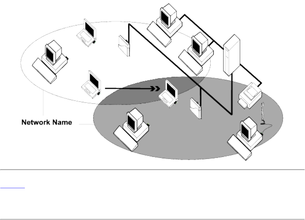
Askey WLL6190D25 network
Askey 802.11g / 802.11n WLAN PCI-E Mini Card (Model name : WLL6190D25) using Broadcom Wireless Utility to connect network.
The
Askey WLL6190D25 solution allows you to make a wireless connection to a network, as illustrated below.
within range. Before you can connect to these and other wireless networks,
you must configure a profile for each network using the
Using the Broadcom Wireless Utility: Broadcom AirForce™ 54g™ and Intensi-fi™ Wireless Network Adapter User Guide
Back to Contents Page
Using the Broadcom Wireless Utility: Broadcom
AirForce™ 54g™ and Intensi-fi™ Wireless Network
Adapter User Guide
Overview
Utility Components
Overview
The Broadcom Wireless Utility enables you to do the following network tasks:
● Manage your wireless networks and create network connection profiles (Wireless Networks tab)
● Connect to available networks (utility icon in notification area)
● Get information about the network status and signal and noise of your network connection (Link
Status tab)
● View current and accumulated statistics (Statistics tab)
● Find out which broadcasting networks are in range and search for nonbroadcasting networks (Site
Monitor tab)
● Run tests on the wireless network adapter (Diagnostics tab)
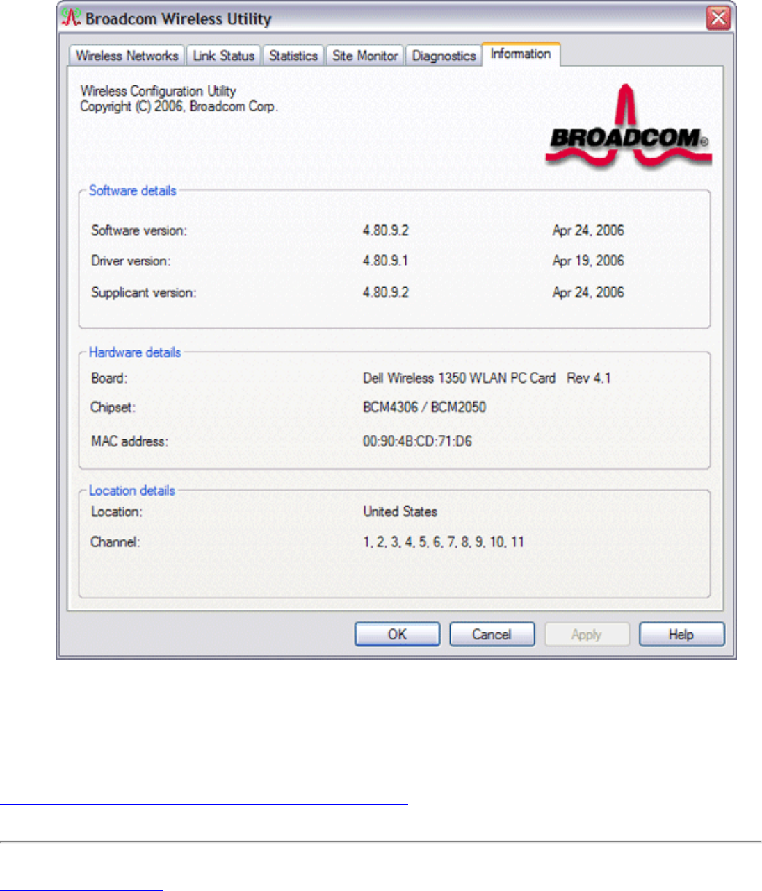
● Get date and version information about the utility, and software, hardware, and location details
about your wireless network adapter (Information tab)
● Manually add or delete trusted servers and enable the manual acceptance or rejection of auto-
provisioning and A-ID group changes (Wireless Networks tab)
● Manually import EAP-FAST PACs (Wireless Networks tab)
In the utility, you can open Wireless Network Wizard to connect to a basic network or create an ad hoc
network, or you can open the Wireless Network Connection Settings tool to connect to an advanced
network. To do any of the other tasks, click the tab that is associated with the described task.
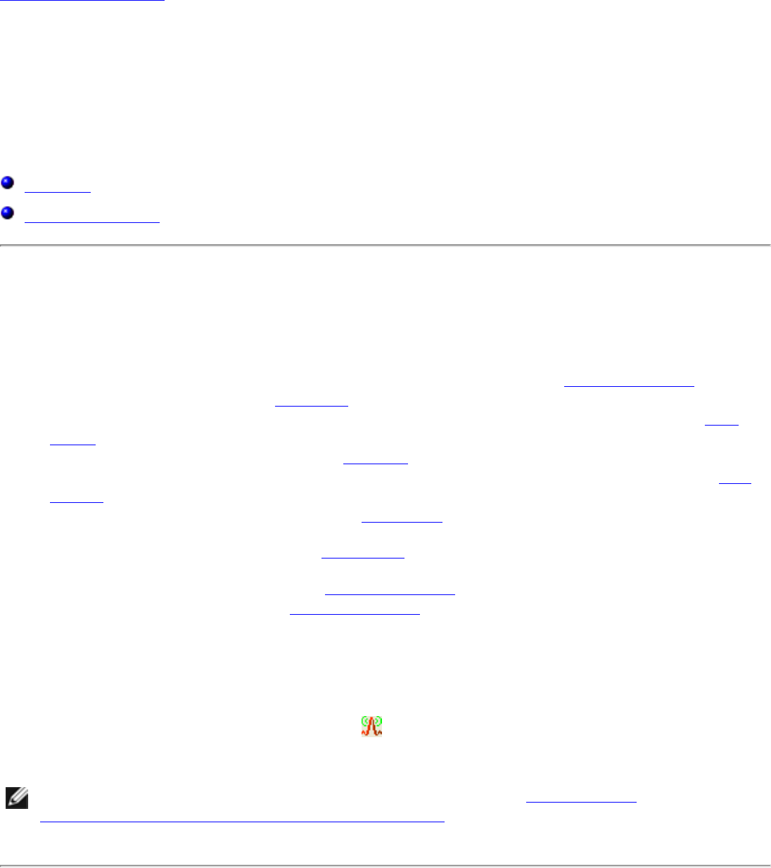
To start using the utility, right-click the utility icon in the notification area, and then click Open Utility.
If the icon is not available, open Broadcom Wireless Utility in Control Panel.
NOTE: The utility icon may not appear exactly as shown here. See "Table 1. Signal
Strength Indicated by the Broadcom Wireless Utility Icon."
Utility Components
Utility components include the utility icon in the notification area, the six utility tabs, and Wireless Network
Connection Settings.
file:///P|/User%20Manuals/WLANCard-UM302_LaLa/HTML/utility.htm (1 of 12)4/25/2006 1:57:41 PM

Using the Broadcom Wireless Utility: Broadcom AirForce™ 54g™ and Intensi-fi™ Wireless Network Adapter User Guide
Utility Icon
To do any of the following tasks or operations, right-click the utility icon, and then click the appropriate
item.
● Open the on-line Broadcom AirForce™ 54g™ and Intensi-fi™ Wireless Network Adapter User Guide
(Help Files)
● Open About WLAN Card Utility to view links to Broadcom and Broadcom Customer Support websites
and to view the version and date of the utility (About)
● Hide the utility icon (Hide Tray Icon)
● Disable or enable the radio (Disable/Enable Radio)
● Connect to any of the networks for which you have created a connection profile and are within
range (Connect To)
● Open the utility to the Wireless Networks tab (Open Utility)
● Open the utility to the Link Status tab to view information about the connection (Status)
● Display a log of your wireless network events (Display Log)
Wireless Networks Tab
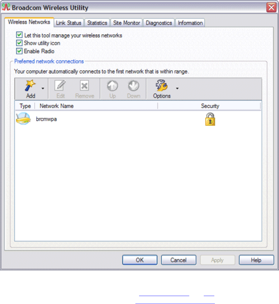
The Wireless Networks tab has tools that enable you to do the following:
● Use the utility to manage your wireless networks
● Add a network connection profile
● Edit or remove a network connection profile
● Change the order in which profiles are listed under Preferred network connections
● Connect to any listed network without changing its order in the list
● Disable or enable the radio (Disable/Enable Radio)
● Show or hide the utility icon in the notification area
● Choose which type of network to access
● Lock or unlock a preferred network connection profile
● Save your wireless network connection profiles as a WPN file
● Import a WPN file
● Manually add or delete trusted servers and enable the manual acceptance or rejection of auto-
provisioning and A-ID group changes
● Manually import EAP-FAST PACS
On the Add menu, you can use either the wireless network wizard that is available from Broadcom
Wireless Utility (see Connecting to a Basic Network or Creating an Ad Hoc Network Using the Wireless
Network Wizard") or the utility (see "Connecting to an Advanced Network Using the Broadcom Wireless
Utility") to add a network connection profile.
To use the utility to manage your wireless networks, select the Let this tool manage your wireless
networks check box.
To add a network connection profile, click the Add arrow, and then click either Use Wizard (basic
network) or Use Utility (advanced network).
To edit or remove a network connection profile, right-click the network name, and then click either Edit or
Remove.
To change the order in which profiles are listed under Preferred network connections, click the network
name, and then click either the up arrow or down arrow.
To connect to any listed network without changing its order in the list, right-click the network name, and
then click Connect.
file:///P|/User%20Manuals/WLANCard-UM302_LaLa/HTML/utility.htm (2 of 12)4/25/2006 1:57:41 PM

Using the Broadcom Wireless Utility: Broadcom AirForce™ 54g™ and Intensi-fi™ Wireless Network Adapter User Guide
To disable the radio, clear the Enable radio check box. To enable the radio, select the Enable radio
check box.
To hide the utility icon , clear the Show utility icon check box. To show the icon, select the Show
utility icon check box.
To choose the type of network to access, click the Options arrow, and then click Advanced.
To lock or unlock a preferred network connection profile, right-click anywhere in the row that lists the
network name, and then click Lock or Unlock, as appropriate.
NOTE: You must have system or administrator rights to be able to lock or unlock a
profile.
To save your wireless network connection profiles to a WPN file, click the Options arrow, and then click
Export (see "Saving Preferred Network Connection Settings to a File" in "Connecting to an Advanced
Network Using the Broadcom Wireless Utility."
To import a WPN file, click the Options arrow, and then click Import (see "Importing a Preferred Network
Connection Profiles File" in "Connecting to an Advanced Network Using the Broadcom Wireless Utility."
Click Apply or OK after you change any of the settings for the change to take effect.
file:///P|/User%20Manuals/WLANCard-UM302_LaLa/HTML/utility.htm (3 of 12)4/25/2006 1:57:41 PM
Using the Broadcom Wireless Utility: Broadcom AirForce™ 54g™ and Intensi-fi™ Wireless Network Adapter User Guide
For networks that use the EAP-FAST authentication method, the Wireless WLAN Card Utility automatically
adds trusted servers to the trust list and accepts auto-provisioning and AID (A-ID) group changes by
default. The utility also enables you to import a Protected Access Credential (PAC). From the utility, you
can also manually add or delete trusted servers, enable the manual acceptance or rejection of auto-
provisioning and A-ID group changes, or import or delete PACS, as described in the following instructions.
In general, you should use the default settings. Therefore, check with the network administrator before you
make any changes.
To manually add a trusted server to the trust list
1. Open Broadcom Wireless Utility.
2. From the Wireless Networks tab, click Options, point to Cisco Compatible Extensions, and
then click Administrator Settings.
3. Click Add.
4. Type the A-ID friendly name of the trusted server in the space provided, and then click OK.
To delete a trusted server from the trust list
file:///P|/User%20Manuals/WLANCard-UM302_LaLa/HTML/utility.htm (4 of 12)4/25/2006 1:57:41 PM

Using the Broadcom Wireless Utility: Broadcom AirForce™ 54g™ and Intensi-fi™ Wireless Network Adapter User Guide
1. Open Broadcom Wireless Utility.
2. From the Wireless Networks tab, click Options, point to Cisco Compatible Extensions, and
then click Administrator Settings.
3. In the Trust list (A-ID), click the name of the trusted server you want to delete, and then click
Delete.
To change the default settings for administering Cisco Compatible Extensions
1. Open Broadcom Wireless Utility.
2. From the Wireless Networks tab, click Options, point to Cisco Compatible Extensions, and
then click Administrator Settings.
3. Clear the Disable auto-provision prompt check box to enable manual acceptance or rejection.
4. Clear the Disable A-ID group change prompt check box to enable manual acceptance or
rejection.
5. Select the Auto-provision PAC only once check box to auto-provision a Protected Access
Credential (PAC) only once.
To import or remove an EAP-FAST PAC
1. Open Broadcom Wireless Utility.
2. From the Wireless Networks tab, click Options, point to Cisco Compatible Extensions, and
then click Manage PACs.
3. To import a PAC: in Protected Access Credentials, click Add, and then follow the on-screen
instructions.
NOTE: The PAC is password protected, so you must know the password to be able to import the
PAC.
-or-
To remove a PAC: click anywhere in the row that lists the PAC, and then click Remove.
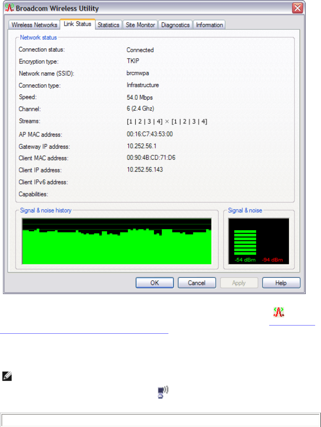
Link Status
Network status and signal and noise information about your network connection is displayed on the Link
Status tab.
NOTES:
● For IEEE 802.11n connections, speed is indicated by an MCS value.
● Radio Stream information is provided only for IEEE 802.11n connections.
● Click anywhere in the Signal & noise history box to change the type of history
being displayed. Successive clicks change the type from both signal and noise,
to noise only, to signal only, and back to both signal and noise.
file:///P|/User%20Manuals/WLANCard-UM302_LaLa/HTML/utility.htm (5 of 12)4/25/2006 1:57:41 PM
Using the Broadcom Wireless Utility: Broadcom AirForce™ 54g™ and Intensi-fi™ Wireless Network Adapter User Guide
The status of your network connection is also indicated by the appearance of the utility icon . The
number and color of the radio waves indicates the strength or weakness of the signal (see Table 1. Signal
Strength Indicated by the Broadcom Wireless Utility Icon for details).
To view the network name (SSID), speed, signal strength rating, connection status, and the client IP
address of the network connection, move your mouse pointer over the utility icon.
NOTE: On computers running Windows XP, you also can view the SSID, speed, signal
strength rating, and connection status by moving your mouse pointer over the
Windows Wireless Network Connection icon in the notification area.
Table 1. Signal Strength Indicated by the Broadcom Wireless Utility Icon
file:///P|/User%20Manuals/WLANCard-UM302_LaLa/HTML/utility.htm (6 of 12)4/25/2006 1:57:41 PM

Using the Broadcom Wireless Utility: Broadcom AirForce™ 54g™ and Intensi-fi™ Wireless Network Adapter User Guide
Icon
Appearance Indicated Received Signal Strength
The signal strength is very good or excellent.
The signal strength is weak. See Troubleshooting for suggested action.
No signal is being received. See Troubleshooting for probable causes and suggested
action.
The radio is disabled or switched off. See Troubleshooting for suggested action.
Statistics
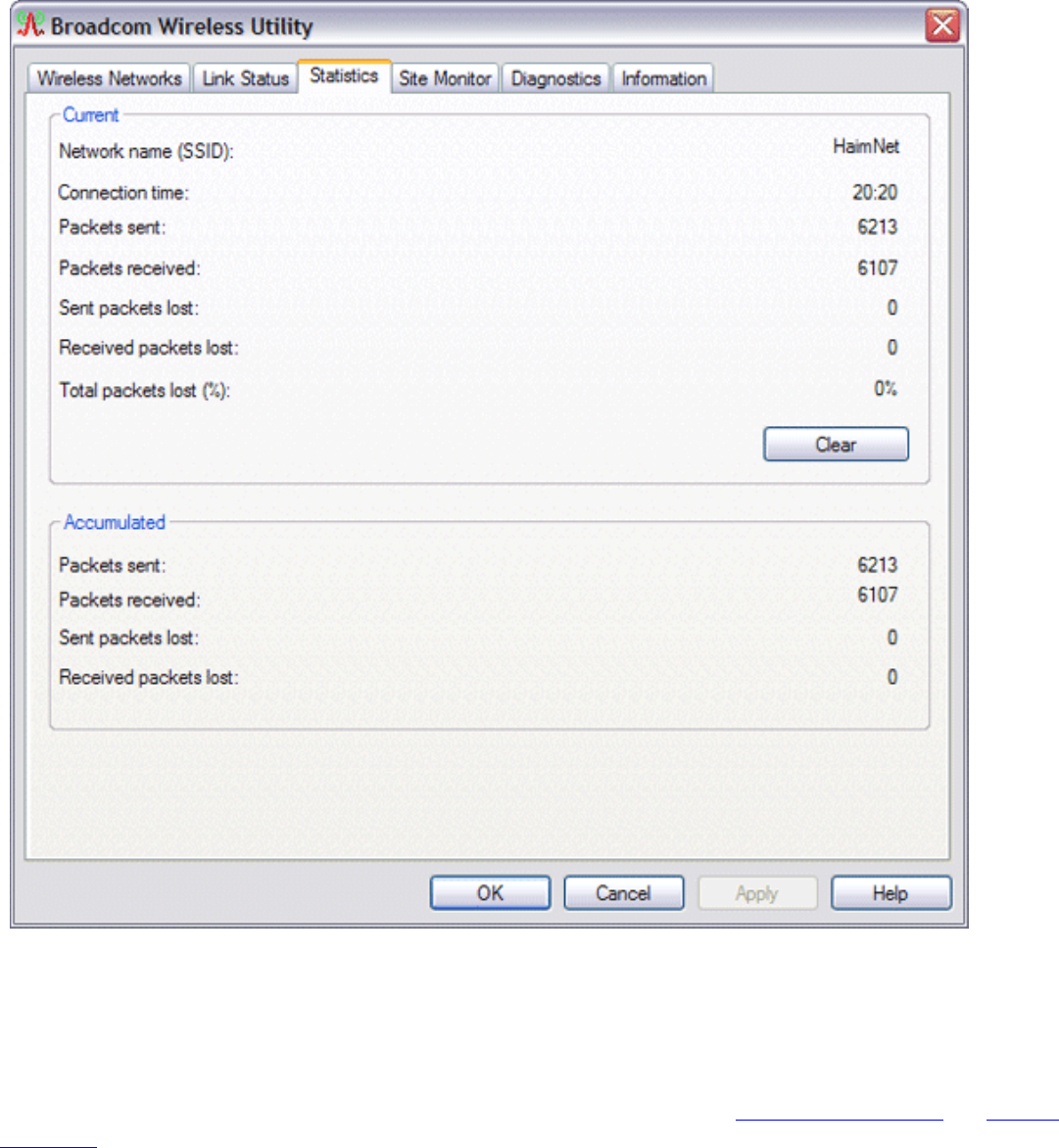
On the Statistics tab under Current, the following current statistics are shown:
● Network name (SSID)
● Connection time
● Packets sent
● Packets received
● Sent packets lost
● Received packets lost
● Total packets lost (%)
Under Accumulated, the following accumulated statistics are shown:
● Packets sent
● Packets received
● Sent packets lost
● Received packets lost
file:///P|/User%20Manuals/WLANCard-UM302_LaLa/HTML/utility.htm (7 of 12)4/25/2006 1:57:41 PM
Using the Broadcom Wireless Utility: Broadcom AirForce™ 54g™ and Intensi-fi™ Wireless Network Adapter User Guide
Site Monitor
Basic Site Monitor
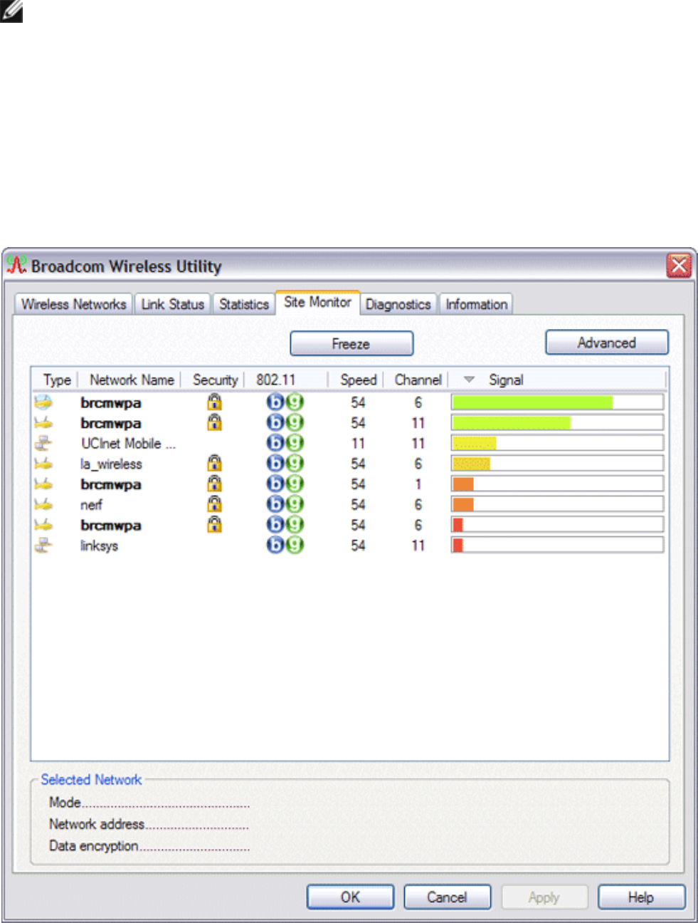
On the Site Monitor tab, the basic Site Monitor displays information about wireless routers/APs and ad hoc
networks that are within range. To sort the list, click the column heading that shows the characteristic you
want to sort by. For example, to sort by signal strength, click Signal .
To view information about a particular wireless router/AP or ad hoc network, click anywhere in the row that
lists the wireless router/AP or ad hoc network. The network information is shown under Selected Network.
To view or change the network connection settings for a particular wireless router/AP or ad hoc network,
right-click anywhere in the row that lists the wireless router/AP or ad hoc network, and then click Edit—if
you have not yet created a network connection profile for that particular wireless router/AP or ad hoc
network and want to do so, click Add .
To see the information elements for a listed AP or ad hoc network, right-click anywhere in the row that lists
the AP or ad hoc network, and then click Show Information Elements.
file:///P|/User%20Manuals/WLANCard-UM302_LaLa/HTML/utility.htm (8 of 12)4/25/2006 1:57:41 PM
Using the Broadcom Wireless Utility: Broadcom AirForce™ 54g™ and Intensi-fi™ Wireless Network Adapter User Guide
NOTES:
● Nonbroadcasting networks are labeled (nonbroadcasting) under Network Name.
● The network performance may be degraded while Site Monitor is displaying
nonbroadcasting APs to which you are not currently connected.
● The symbols under AP Band indicate IEEE 802.11b, IEEE
802.11g, or IEEE 802.11n operation.
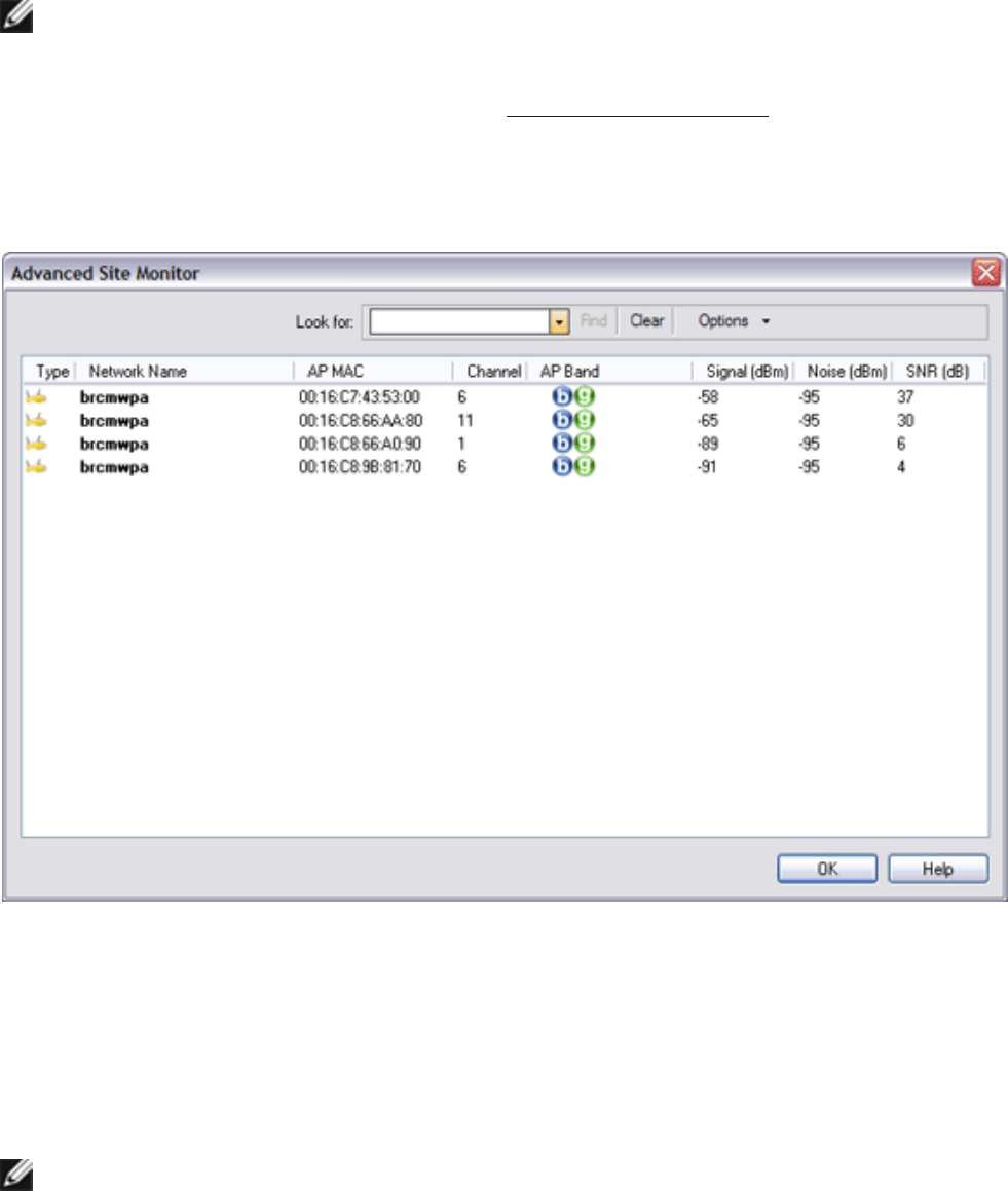
To see more detailed information about a particular wireless router/AP or ad hoc network, click anywhere
in the row that lists the wireless router/AP or ad hoc network, and then click Advanced.
Advanced Site Monitor
To save the activity log to a file, click the Options arrow, and then click Start Log.
file:///P|/User%20Manuals/WLANCard-UM302_LaLa/HTML/utility.htm (9 of 12)4/25/2006 1:57:41 PM
Using the Broadcom Wireless Utility: Broadcom AirForce™ 54g™ and Intensi-fi™ Wireless Network Adapter User Guide
You can adjust the time interval between scans by clicking the Options arrow, and then clicking either one
of the preset values or clicking Customize to specify a different time interval.
NOTE: The network performance may be degraded while Site Monitor is displaying
nonbroadcasting networks to which you are not currently connected.
To view detailed network information for a single nonbroadcasting network, type the network name in the
Look for box, and then click Find.
To reset the site monitor to the broadcasting networks, click Clear.
Diagnostics
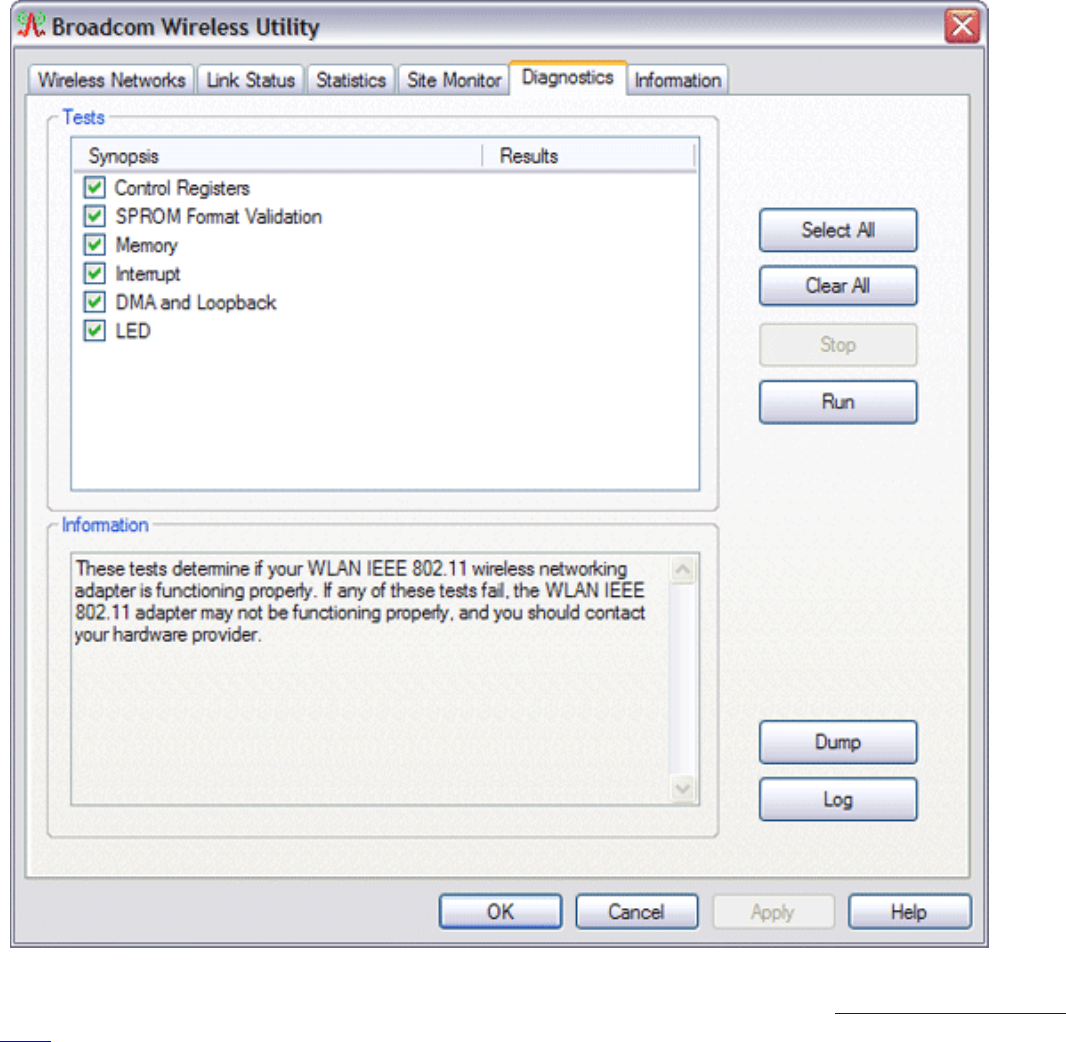
On the Diagnostics tab, you can run a number of tests to determine if your wireless network adapter is
functioning properly. Select the tests you want to run, and then click Run. For information about an
individual test, look under Information before you click Run. To see the test results, look under
Information after you click Run.
NOTE: The network connection is lost when you run the tests. When the test run is
over, your network connection is automatically reestablished.
Also, you can view a log of your wireless network events. To do so, click Log.
Examples of wireless network events that are logged include:
file:///P|/User%20Manuals/WLANCard-UM302_LaLa/HTML/utility.htm (10 of 12)4/25/2006 1:57:41 PM
Using the Broadcom Wireless Utility: Broadcom AirForce™ 54g™ and Intensi-fi™ Wireless Network Adapter User Guide
● Initiation of user session
● Connecting to a network
● Disconnecting from current network
● Authentication mode being used
● Driver status
● Supplicant status
● New wireless device available
● Initializing wireless state machine
● Wireless utility is managing this adapter
● Wireless utility is not managing this adapter
If your Broadcom 802.11 Network Adapter fails any of the diagnostics tests, go to http://www.broadcom.
com/ for technical support.
Information
file:///P|/User%20Manuals/WLANCard-UM302_LaLa/HTML/utility.htm (11 of 12)4/25/2006 1:57:41 PM
Using the Broadcom Wireless Utility: Broadcom AirForce™ 54g™ and Intensi-fi™ Wireless Network Adapter User Guide
The following information is displayed on the Information tab:
●
Software details
●
Hardware details
Wireless Network Connection Settings
The Wireless Network Connection Settings component is intended for use by advanced users or network
administrators. You can use Wireless Network Connection Settings to create a connection profile for an
advanced infrastructure network, a basic infrastructure network, or an ad hoc network (see " Connecting to
an Advanced Network Using the Broadcom Wireless Utility").
Back to Contents Page
file:///P|/User%20Manuals/WLANCard-UM302_LaLa/HTML/utility.htm (12 of 12)4/25/2006 1:57:41 PM
Federal Communication Commission Interference Statement
This device complies with Part 15 of the FCC Rules. Operation is subject to
the following two conditions: (1) This device may not cause harmful
interference, and (2) this device must accept any interference received,
including interference that may cause undesired operation.
This equipment has been tested and found to comply with the limits for a
Class B digital device, pursuant to Part 15 of the FCC Rules. These limits
are designed to provide reasonable protection against harmful interference in a
residential installation. This equipment generates, uses and can radiate radio
frequency energy and, if not installed and used in accordance with the
instructions, may cause harmful interference to radio communications.
However, there is no guarantee that interference will not occur in a particular
installation. If this equipment does cause harmful interference to radio or
television reception, which can be determined by turning the equipment off
and on, the user is encouraged to try to correct the interference by one of the
following measures:
- Reorient or relocate the receiving antenna.
- Increase the separation between the equipment and receiver.
- Connect the equipment into an outlet on a circuit different from that
to which the receiver is connected.
- Consult the dealer or an experienced radio/TV technician for help.
FCC Caution: Any changes or modifications not expressly approved by the
party responsible for compliance could void the user's authority to operate this
equipment.
This transmitter must not be co-located or operating in conjunction with any
other antenna or transmitter.
Radiation Exposure Statement:
This equipment complies with FCC radiation exposure limits set forth for an
uncontrolled environment. This equipment should be installed and operated
with minimum distance 20cm between the radiator & your body.

This device is intended only for OEM integrators under the following conditions:
1) The antenna must be installed such that 20 cm is maintained between the
antenna and users, and
2) The transmitter module may not be co-located with any other transmitter or
antenna.
As long as 2 conditions above are met, further transmitter test will not be
required. However, the OEM integrator is still responsible for testing their
end-product for any additional compliance requirements required with this
module installed
IMPORTANT NOTE: In the event that these conditions can not be met (for
example certain laptop configurations or co-location with another transmitter),
then the FCC authorization is no longer considered valid and the FCC ID can
not be used on the final product. In these circumstances, the OEM integrator will
be responsible for re-evaluating the end product (including the transmitter) and
obtaining a separate FCC authorization.
End Product Labeling
This transmitter module is authorized only for use in device where the antenna
may be installed such that 20 cm may be maintained between the antenna and
users. The final end product must be labeled in a visible area with the following:
“Contains FCC ID: H8N-WLL6190D25”. The grantee's FCC ID can be used
only when all FCC compliance requirements are met.
Manual Information To the End User
The OEM integrator has to be aware not to provide information to the end user
regarding how to install or remove this RF module in the user’s manual of the
end product which integrates this module.
The end user manual shall include all required regulatory information/warning as
show in this manual.
Industry Canada statement:
This device complies with RSS-210 of the Industry Canada Rules. Operation is
subject to the following two conditions: (1) This device may not cause harmful
interference, and (2) this device must accept any interference received, including
interference that may cause undesired operation.
Ce dispositif est conforme à la norme CNR-210 d'Industrie Canada applicable aux
appareils radio exempts de licence. Son fonctionnement est sujet aux deux conditions
suivantes: (1) le dispositif ne doit pas produire de brouillage préjudiciable, et (2) ce
dispositif doit accepter tout brouillage reçu, y compris un brouillage susceptible de
provoquer un fonctionnement indésirable.
Radiation Exposure Statement:
This equipment complies with IC radiation exposure limits set forth for an
uncontrolled environment. This equipment should be installed and operated with
minimum distance 20cm between the radiator & your body.
Déclaration d'exposition aux radiations:
Cet équipement est conforme aux limites d'exposition aux rayonnements IC établies
pour un environnement non contrôlé. Cet équipement doit être installé et utilisé avec
un minimum de 20 cm de distance entre la source de rayonnement et votre corps.
This device is intended only for OEM integrators under the following conditions: (For
module device use)
1) The antenna must be installed such that 20 cm is maintained between the antenna
and users, and
2) The transmitter module may not be co-located with any other transmitter or
antenna.
As long as 2 conditions above are met, further transmitter test will not be required.
However, the OEM integrator is still responsible for testing their end-product for any
additional compliance requirements required with this module installed.
Cet appareil est conçu uniquement pour les intégrateurs OEM dans les conditions
suivantes: (Pour utilisation de dispositif module)
1) L'antenne doit être installée de telle sorte qu'une distance de 20 cm est
respectée entre l'antenne et les utilisateurs, et
2) Le module émetteur peut ne pas être coïmplanté avec un autre émetteur ou
antenne.
Tant que les 2 conditions ci-dessus sont remplies, des essais supplémentaires sur
l'émetteur ne seront pas nécessaires. Toutefois, l'intégrateur OEM est toujours
responsable des essais sur son produit final pour toutes exigences de conformité
supplémentaires requis pour ce module installé.
IMPORTANT NOTE:
In the event that these conditions can not be met (for example certain laptop
configurations or co-location with another transmitter), then the Canada authorization
is no longer considered valid and the IC ID can not be used on the final product. In
these circumstances, the OEM integrator will be responsible for re-evaluating the end
product (including the transmitter) and obtaining a separate Canada authorization.
NOTE IMPORTANTE:
Dans le cas où ces conditions ne peuvent être satisfaites (par exemple pour certaines
configurations d'ordinateur portable ou de certaines co-localisation avec un autre
émetteur), l'autorisation du Canada n'est plus considéré comme valide et l'ID IC ne
peut pas être utilisé sur le produit final. Dans ces circonstances, l'intégrateur OEM
sera chargé de réévaluer le produit final (y compris l'émetteur) et l'obtention d'une
autorisation distincte au Canada.
End Product Labeling
This transmitter module is authorized only for use in device where the antenna may be
installed such that 20 cm may be maintained between the antenna and users. The final
end product must be labeled in a visible area with the following: “Contains IC:
1353A-WLL6190D25”.
Plaque signalétique du produit final
Ce module émetteur est autorisé uniquement pour une utilisation dans un dispositif où
l'antenne peut être installée de telle sorte qu'une distance de 20cm peut être maintenue
entre l'antenne et les utilisateurs. Le produit final doit être étiqueté dans un endroit
visible avec l'inscription suivante: "Contient des IC: 1353A-WLL6190D25".
Manual Information To the End User
The OEM integrator has to be aware not to provide information to the end user
regarding how to install or remove this RF module in the user’s manual of the end

product which integrates this module.
The end user manual shall include all required regulatory information/warning as
show in this manual.
Manuel d'information à l'utilisateur final
L'intégrateur OEM doit être conscient de ne pas fournir des informations à l'utilisateur
final quant à la façon d'installer ou de supprimer ce module RF dans le manuel de
l'utilisateur du produit final qui intègre ce module.
Le manuel de l'utilisateur final doit inclure toutes les informations réglementaires
requises et avertissements comme indiqué dans ce manuel.
DETACHABLE ANTENNA USAGE
This device has been designed to operate with an antenna having a maximum gain of
2 dBi. Antenna having a higher gain is strictly prohibited per regulations of Industry
Canada. The required antenna impedance is 50 ohms.
Under Industry Canada regulations, this radio transmitter may only operate using an
antenna of a type and maximum (or lesser) gain approved for the transmitter by
Industry Canada. To reduce potential radio interference to other users, the antenna
type and its gain should be so chosen that the equivalent isotropically radiated power
(e.i.r.p.) is not more than that necessary for successful communication.
This radio transmitter (IC: 1353A-WLL6190D25 / Model: WLL6190D25) has been
approved by Industry Canada to operate with the antenna types listed below with the
maximum permissible gain and required antenna impedance for each antenna type
indicated. Antenna types not included in this list, having a gain greater than the
maximum gain indicated for that type, are strictly prohibited for use with this device.
Ce dispositif a été conçu pour fonctionner avec une antenne ayant un gain maximal de
dBi 2. Une antenne à gain plus élevé est strictement interdite par les règlements
d'Industrie Canada. L'impédance d'antenne requise est de 50 ohms.
Conformément à la réglementation d'Industrie Canada, le présent émetteur radio
peutfonctionner avec une antenne d'un type et d'un gain maximal (ou inférieur)
approuvé pourl'émetteur par Industrie Canada. Dans le but de réduire les risques de
brouillage radioélectriqueà l'intention des autres utilisateurs, il faut choisir le type
d'antenne et son gain de sorte que lapuissance isotrope rayonnée équivalente (p.i.r.e.)

ne dépasse pas l'intensité nécessaire àl'établissement d'une communication
satisfaisante.
Le présent émetteur radio (IC: 1353A-WLL6190D25 / Model: WLL6190D25) a été
approuvé par Industrie Canada pour fonctionner avec les types d'antenne énumérés
ci-dessous et ayant un gain admissible maximal et l'impédance requise pour chaque
type d'antenne. Les types d'antenne non inclus dans cette liste, ou dont le gain est
supérieur au gain maximal indiqué, sont strictement interdits pour l'exploitation de
l'émetteur.
Approved antenna(s) list
Type Gain Brand Manufacturer
Dipole 2dBi
KINSUN KINSUN
PIFA 2dBi N/A N/A
