Asus Intel 810 Motherboard P3W Users Manual
p3w-102 p3w-102
P3W to the manual 02b45209-21f2-4c78-b776-48d33afe0d49
2015-01-21
: Asus Asus-Intel-810-Motherboard-P3W-Users-Manual-237693 asus-intel-810-motherboard-p3w-users-manual-237693 asus pdf
Open the PDF directly: View PDF ![]() .
.
Page Count: 128 [warning: Documents this large are best viewed by clicking the View PDF Link!]

®
P3W
Intel® 810 Motherboard
USER’S MANUAL

2ASUS P3W User’s Manual
USER'S NOTICE
Product Name: ASUS P3W
Manual Revision: 1.02 E452
Release Date: September 1999
No part of this manual, including the products and software described in it, may be repro-
duced, transmitted, transcribed, stored in a retrieval system, or translated into any language in
any form or by any means, except documentation kept by the purchaser for backup purposes,
without the express written permission of ASUSTeK COMPUTER INC. (“ASUS”).
ASUS PROVIDES THIS MANUAL “AS IS” WITHOUT WARRANTY OF ANY KIND,
EITHER EXPRESS OR IMPLIED, INCLUDING BUT NOT LIMITED TO THE IMPLIED
WARRANTIES OR CONDITIONS OF MERCHANTABILITY OR FITNESS FOR A PAR-
TICULAR PURPOSE. IN NO EVENT SHALL ASUS, ITS DIRECTORS, OFFICERS,
EMPLOYEES OR AGENTS BE LIABLE FOR ANY INDIRECT, SPECIAL, INCIDEN-
TAL, OR CONSEQUENTIAL DAMAGES (INCLUDING DAMAGES FOR LOSS OF
PROFITS, LOSS OF BUSINESS, LOSS OF USE OR DATA, INTERRUPTION OF BUSI-
NESS AND THE LIKE), EVEN IF ASUS HAS BEEN ADVISED OF THE POSSIBILITY
OF SUCH DAMAGES ARISING FROM ANY DEFECT OR ERROR IN THIS MANUAL
OR PRODUCT.
Product warranty or service will not be extended if: (1) the product is repaired, modified or
altered, unless such repair, modification of alteration is authorized in writing by ASUS; or (2)
the serial number of the product is defaced or missing.
Products and corporate names appearing in this manual may or may not be registered trade-
marks or copyrights of their respective companies, and are used only for identification or
explanation and to the owners’ benefit, without intent to infringe.
• QuickStart and JumperFree are trademarks of ASUSTeK Computer Inc.
• Intel, LANDesk, and Pentium are registered trademarks of Intel Corporation.
• IBM and OS/2 are registered trademarks of International Business Machines.
• XGstudio and SoftSynthesizer are registered trademarks of Yamaha Corporation.
• Symbios is a registered trademark of Symbios Logic Corporation.
• Windows and MS-DOS are registered trademarks of Microsoft Corporation.
• Adobe and Acrobat are registered trademarks of Adobe Systems Incorporated.
The product name and revision number are both printed on the product itself. Manual revi-
sions are released for each product design represented by the digit before and after the period
of the manual revision number. Manual updates are represented by the third digit in the manual
revision number.
For previous or updated manuals, BIOS, drivers, or product release information, contact ASUS
at http://www.asus.com.tw or through any of the means indicated on the following page.
SPECIFICATIONS AND INFORMATION CONTAINED IN THIS MANUAL ARE FUR-
NISHED FOR INFORMATIONAL USE ONLY, AND ARE SUBJECT TO CHANGE AT
ANY TIME WITHOUT NOTICE, AND SHOULD NOT BE CONSTRUED AS A COM-
MITMENT BY ASUS. ASUS ASSUMES NO RESPONSIBILITY OR LIABILITY FOR
ANY ERRORS OR INACCURACIES THAT MAY APPEAR IN THIS MANUAL, INCLUD-
ING THE PRODUCTS AND SOFTWARE DESCRIBED IN IT.
Copyright © 1999 ASUSTeK COMPUTER INC. All Rights Reserved.

ASUS P3W User’s Manual 3
ASUS CONTACT INFORMATION
ASUSTeK COMPUTER INC. (Asia-Pacific)
Marketing
Address: 150 Li-Te Road, Peitou, Taipei, Taiwan 112
Telephone: +886-2-2894-3447
Fax: +886-2-2894-3449
Email: info@asus.com.tw
Technical Support
MB/Cards (tel): English: +886-2-2890-7121
Notebook (tel): English: +886-2-2890-7122
Server (tel): English: +886-2-2890-7123
Fax: +886-2-2895-9254
Email: tsd@asus.com.tw
Newsgroup: news2.asus.com.tw
WWW: www.asus.com.tw
FTP: ftp.asus.com.tw/pub/ASUS
ASUS COMPUTER INTERNATIONAL (America)
Marketing
Address: 6737 Mowry Avenue, Mowry Business Center, Building 2
Newark, CA 94560, USA
Fax: +1-510-608-4555
Email: info-usa@asus.com.tw
Technical Support
Fax: +1-510-608-4555
BBS: +1-510-739-3774
Email: tsd@asus.com
WWW: www.asus.com
FTP: ftp.asus.com/Pub/ASUS
ASUS COMPUTER GmbH (Europe)
Marketing
Address: Harkort Str. 25, 40880 Ratingen, BRD, Germany
Telephone: MB/Other: +49-2102-9599-0 Notebook: +49-2102-9599-10
Fax: +49-2102-9599-11
Email: info@asuscom.de
Technical Support
Hotline: MB/Other: +49-2102-9599-0 Notebook: +49-2102-9599-10
Email: tsd@asuscom.de
WWW: www.asuscom.de
FTP: ftp.asuscom.de/pub/ASUSCOM

4ASUS P3W User’s Manual
CONTENTS
1. INTRODUCTION ............................................................................. 7
1.1 How This Manual Is Organized .................................................. 7
1.2 Item Checklist ............................................................................. 7
2. FEATURES ........................................................................................ 8
2.1 The ASUS P3W Motherboard .................................................... 8
2.1.1 Specifications ..................................................................... 8
2.1.2 Optional Component(s)...................................................... 9
2.1.3 Performance ..................................................................... 10
2.1.4 Intelligence....................................................................... 11
2.2 Motherboard Part Definitions ................................................... 12
2.3 Motherboard Part Locations ..................................................... 13
3. HARDWARE SETUP ..................................................................... 14
3.1 Motherboard Layout ................................................................. 14
3.2 Layout Contents ........................................................................ 15
3.3 Hardware Setup Procedure ....................................................... 17
3.4 Motherboard Settings ................................................................ 17
3.5 System Memory (DIMM) ......................................................... 24
3.5.1 General DIMM Notes ...................................................... 24
3.5.2 DIMM Installation ........................................................... 25
3.6 Central Processing Unit (CPU) ................................................. 26
3.6.1 Universal Retention Mechanism...................................... 26
3.6.2 Heatsinks.......................................................................... 27
3.6.3 Installing the Processor .................................................... 27
3.6.4 Recommended Heatsinks for Slot 1 Processors .............. 29
3.6.5 Precautions ....................................................................... 30
3.7 Expansion Cards ....................................................................... 31
3.7.1 Expansion Card Installation Procedure............................ 31
3.7.2 Assigning IRQs for Expansion Cards .............................. 32
3.7.3 Assigning DMA Channels for ISA Cards ........................ 34
3.7.4 Audio Modem Riser (AMR) Slot .................................... 34
3.8 External Connectors .................................................................. 35
3.9 Power Connection Procedures .................................................. 47
4. BIOS SETUP..................................................................................... 48
4.1 Managing and Updating Your BIOS ......................................... 48
4.1.1 Upon First Use of the Computer System ......................... 48
4.1.2 Updating BIOS Procedures.............................................. 49
4.2 BIOS Setup Program ................................................................ 51
4.2.1 BIOS Menu Bar ............................................................... 52
4.2.2 Legend Bar....................................................................... 52
4.3 Main Menu ................................................................................ 54
4.3.1 Primary & Secondary Master/Slave ................................ 55

ASUS P3W User’s Manual 5
CONTENTS
4.4 Advanced Menu ........................................................................ 60
4.4.1 Chip Configuration .......................................................... 62
4.4.2 I/O Device Configuration ................................................ 65
4.4.3 PCI Configuration ............................................................ 67
4.4.4 Shadow Configuration ..................................................... 70
4.5 Power Menu .............................................................................. 71
4.5.1 Power Up Control ............................................................ 73
4.5.2 Hardware Monitor............................................................ 75
4.6 Boot Menu ................................................................................ 76
4.7 Exit Menu ................................................................................. 78
5. SOFTWARE SETUP ........................................................................ 81
5.1 ASUS Smart Motherboard Support CD.................................... 81
5.2 Operating Systems .................................................................... 84
5.3 Starting Windows For the First Time ........................................ 84
5.4 LDCM Local Setup ................................................................... 86
5.5 LDCM Administrator Setup...................................................... 88
5.6 ASUS PC Probe ........................................................................ 91
5.7 ASUS LiveUpdate .................................................................... 92
5.8 Drivers ...................................................................................... 93
5.9 Other ......................................................................................... 95
5.10 Uninstalling Programs ............................................................ 102
6. SOFTWARE REFERENCE .......................................................... 103
6.1 Display Properties ................................................................... 103
6.2 ASUS PC Probe ...................................................................... 107
6.3 ASUS LiveUpdate .................................................................. 112
6.4 Using Yamaha XGstudio Player ............................................. 113
6.5 Using Yamaha XGstudio Mixer .............................................. 114
6.6 Hardware Information............................................................. 116
7. APPENDIX...................................................................................... 117
7.1 PCI-L101 Fast Ethernet Card ................................................. 117
7.2 S370 Series CPU Cards .......................................................... 119
INDEX ................................................................................................. 121

6ASUS P3W User’s Manual
FCC & DOC COMPLIANCE
Federal Communications Commission Statement
This device complies with FCC Rules Part 15. Operation is subject to the following
two conditions:
• This device may not cause harmful interference, and
• This device must accept any interference received, including interference that
may cause undesired operation.
This equipment has been tested and found to comply with the limits for a Class B
digital device, pursuant to Part 15 of the FCC Rules. These limits are designed to
provide reasonable protection against harmful interference in a residential installa-
tion. This equipment generates, uses and can radiate radio frequency energy and, if
not installed and used in accordance with manufacturer's instructions, may cause
harmful interference to radio communications. However, there is no guarantee that
interference will not occur in a particular installation. If this equipment does cause
harmful interference to radio or television reception, which can be determined by
turning the equipment off and on, the user is encouraged to try to correct the interfer-
ence by one or more of the following measures:
• Re-orient or relocate the receiving antenna.
• Increase the separation between the equipment and receiver.
• Connect the equipment to an outlet on a circuit different from that to which the
receiver is connected.
• Consult the dealer or an experienced radio/TV technician for help.
WARNING! Any changes or modifications to this product not expressly ap-
proved by the manufacturer could void any assurances of safety or performance
and could result in violation of Part 15 of the FCC Rules.
Reprinted from the Code of Federal Regulations #47, part 15.193, 1993. Washing-
ton DC: Office of the Federal Register, National Archives and Records Administra-
tion, U.S. Government Printing Office.
Canadian Department of Communications Statement
This digital apparatus does not exceed the Class B limits for radio noise emissions
from digital apparatus set out in the Radio Interference Regulations of the Canadian
Department of Communications.
This Class B digital apparatus complies with Canadian ICES-003.
Cet appareil numérique de la classe B est conforme à la norme NMB-003 du Canada.

ASUS P3W User’s Manual 7
1. INTRODUCTION
Sections/Checklist
1.1 How This Manual Is Organized
This manual is divided into the following sections:
1) INTRODUCTION Manual information and checklist
2) FEATURES Product information and specifications
3) HARDWARE SETUP Instructions on setting up the motherboard
4) BIOS SETUP Instructions on setting up the BIOS software
5) SOFTWARE SETUP Instructions on setting up the included software
6) SOFTWARE REFERENCE Reference material for the included software
7) APPENDIX Optional items
1.2 Item Checklist
Check that your package is complete. If you discover damaged or missing items,
please contact your retailer.
(1) ASUS Motherboard
(1) Universal Retention Mechanism for SECC2/SECC/SEPP processors
(1) 40-pin 80-conductor ribbon cable for internal UltraDMA/66 or UltraDMA/
33 IDE drives
(1) Ribbon cable for (1) 5.25” and (2) 3.5” floppy disk drives
(1) Serial COM2 connector with bracket
(1) Bag of spare jumper caps
(1) Support CD with drivers and utilities
(1) This Motherboard User’s Manual
ASUS consumer infrared set (optional)
ASUS IrDA-compliant infrared module (optional)
ASUS S370 Series CPU card (optional)
ASUS PCI-L101 Wake-On-LAN 10/100 ethernet card (optional)
1. INTRODUCTION

8ASUS P3W User’s Manual
2. FEATURES
Specifications
2. FEATURES
2.1 The ASUS P3W Motherboard
The P3W motherboard from ASUS is carefully designed for the demanding PC user
who wants many smart features in a small package. So what’s so smart about the
ASUS P3W motherboard?
2.1.1 Specifications
•Latest Intel Processor Support! Supports Intel Pentium
®
III (450MHz and
faster), Pentium
®
II (233MHz to 450MHz), and Celeron™ (266MHz and faster)
processors.
•Latest Intel 810 Chipset! Features 100/66MHz FSB Intel 810 chipset with the
Accelerated Hub Architecture, which provides direct connections between the
810 chipset and subsystems such as IDE controllers, USB controllers, and PCI
add-in cards.
•Multi-Cache! Supports processors with 512, 256, 128, or 0KB Pipelined Burst
Level 2 Cache.
•Integrated Graphics! Controller supports 3D hyper pipelined architecture, par-
allel data processing and compression, precise pixel interpolation, full 2D hard-
ware acceleration, and motion video acceleration.
•ASUS Graphics Driver! You can gain about 12% performance over that of the
standard graphics driver (2D high-end graphics WinMark) using ASUS’ custom
graphics driver. ASUS custom graphics driver also provides more features and
provides selection of higher refresh rates and resolutions.
•Versatile Memory Support! DRAM controller supports asymmetrical address-
ing and three DIMM sockets support Intel PC100-compliant SDRAMs (16, 32,
64, 128, or 256MB) up to 512MB. (supports a maximum of 4 sides)
•JumperFree™ Mode! Allows processor settings and easy overclocking of fre-
quency and Vcore voltage all through BIOS setup when JumperFree™ mode is
enabled. Easy-to-use DIP switches instead of jumpers are included incase you
want to manually adjust the processor’s external frequency.
•Smart Slots! Six 32-bit PCI (rev 2.2) slots and one 16-bit ISA expansion slot for
greater expansion flexibility. PCI supports up to 133MB/s maximum through-
put. Each PCI slot can support a Bus Master PCI card (such as SCSI or LAN
cards).
•Latest Low Pin Count Multi-I/O: Provides two high-speed UART compatible
serial ports and one parallel port with EPP and ECP capabilities.
•Integrated IDE! Controller supports UltraDMA/66 up to 66MB/s, UltraDMA/
33 up to 33MB/s, and PIO Mode 4 up to 17MB/s.
•Peripheral Wake-Up! Supports Wake-On-LAN, Wake-On-Ring, Keyboard
Wake-Up, and BIOS Wake-Up.

ASUS P3W User’s Manual 9
2. FEATURES
2. FEATURES
Optional Component(s)
•AMR Slot! Audio Modem Riser slot supports a very affordable audio and/or
modem riser card.
•Around-the-Clock Intrusion Detection! Supports chassis intrusion monitor-
ing through the ASUS ASIC. The onboard battery supports detection even when
normal power is removed and through a new design, battery drain is even lower
than the RTC used for keeping time!
•Firmware Hub! Provides security and other latest power computing features.
•Monitoring for your PC’s Health! Provided ASUS PC Probe or Intel LDCM
allows PC health monitoring.
•Enhanced ACPI & Anti-Boot Virus Protection! Programmable BIOS (Flash
EEPROM), offering enhanced ACPI for Windows 98 compatibility, built-in firm-
ware-based virus protection, and autodetection of most devices for virtually au-
tomatic setup.
•Smart BIOS! 4Mbit firmware gives a new easy-to-use interface which provides
more control and protection over the motherboard. Provides Vcore and CPU/
SDRAM frequency adjustments, boot block write protection, and HD/SCSI/MO/
ZIP/CD/Floppy boot selection. Hardware random number generator supports new
security software for data protection and secured Internet transactions.
2.1.2 Optional Component(s)
The following onboard component(s) are optional at the time of purchase:
•No Messy Wires! Integrated Consumer IR and Serial IR supports an optional
remote control package for wireless interfacing with external peripherals, per-
sonal gadgets, or an optional remote controller.

10 ASUS P3W User’s Manual
2. FEATURES
Performance
2. FEATURES
2.1.3 Performance
•UltraPerformance! Onboard IDE Bus Master controller with two connectors
that support four IDE devices in two channels. Supports UltraDMA/66, UltraDMA/
33 (IDE DMA Mode 2), PIO Modes 3 & 4, and supports Enhanced IDE devices,
such as Tape Backup, CD-ROM, CD-R/RW, and LS-120 drives.
•Dual Speeds! CPU frequency can operate at either 66MHz or 100MHz while
system memory operates at either 100MHz or 66MHz. (100MHz CPU with
66MHz SDRAM setting not supported). For maximum performance, 100MHz/
100MHz synchronous host/DRAM clock is recommended.
•Double or Quadruple the IDE Transfer Speed! IDE transfers using UltraDMA/
33 Bus Master IDE can handle rates up to 33MB/s and up to 66MB/s using
UltraDMA/66 technology. The best of all is that these new technology is com-
patible with existing ATA-2 IDE specifications so there is no need to upgrade
current IDE devices or cables.
•Concurrent PCI! Concurrent PCI allows multiple PCI transfers from PCI mas-
ter buses to memory to CPU.
•SDRAM Optimized Performance! ASUS smart series motherboards support the
new generation memory, Synchronous Dynamic Random Access Memory (SDRAM),
which increases the data transfer rate to 800MB/s max using PC100-compliant
SDRAM.
•ACPI Ready! ACPI (Advanced Configuration and Power Interface) is also imple-
mented on all ASUS smart series motherboards. ACPI provides more Energy
Saving Features for future operating systems (OS) supporting OS Direct Power
Management (OSPM) functionality. With these features implemented in the OS,
PCs can be ready around the clock, yet satisfy all the energy saving standards.
To fully utilize the benefits of ACPI, an ACPI-supported OS, such as Windows
98, must be used.
•Suspend and Go! Suspend-To-RAM (STR) provides maximum power savings
as an alternative to leaving the computer ON and QuickStart™ so that you do
not fall asleep waiting for system bootup. (STR requires OS support and does
not support ISA cards; ISA cards may fail to work coming out of STR mode.)
•New Compliancy! Both the BIOS and hardware levels of the motherboard meet
PC’99 compliancy. The new PC’99 requirements for systems and components are
based on the following high-level goals: Support for Plug and Play compatibility
and power management for configuring and managing all system components,
and 32-bit device drivers and installation procedures for Windows 95/98/NT. Color-
coded connectors and descriptive icons make identification easy as required by
PC’99.
•Highest Audio Quality! AC’97 DAC/ADC built into the audio codec reduces
noise to improve audio quality and performance for a SNR (signal to noise ratio)
of +90dB. These features greatly improve voice synthesis and recognition.
•Extreme Graphics! The integrated motion compensation allows for smooth
MPEG1 or MPEG2 video playback. Fast 3D graphics engine allows for an ex-
citing gameplay experience.

ASUS P3W User’s Manual 11
2.1.4 Intelligence
•Fan Status Monitoring and Alarm! To prevent system overheat and system
damage, the CPU, power supply, and system fans can be monitored for RPM
and failure. All the fans are set for its normal RPM range and alarm thresholds.
•Temperature Monitoring and Alert! CPU temperature is monitored by the
ASUS ASIC through the CPU’s internal thermal diode (on Pentium III, Deschutes
Pentium II, and PPGA 370 Celeron in conjunction with the ASUS S370-D or
S370-L CPU card, see 7.2 S370 Series CPU Cards) to prevent system overheat
and system damage. The temperature reported by the internal thermal diode is
the actual processor core temperature as opposed to the less accurate surface
temperature.
•Voltage Monitoring and Alert! System voltage levels are monitored to ensure
stable current to critical motherboard components. Voltage specifications are
more critical for future processors, so monitoring is necessary to ensure proper
system configuration and management.
•System Resources Alert! Today’s operating systems such as Windows 98, Win-
dows NT, and OS/2, require much more memory and hard drive space to present
enormous user interfaces and run large applications. The system resource moni-
tor will warn the user before the system resources are used up to prevent pos-
sible application crashes. Suggestions will give the user information on manag-
ing their limited resources more efficiently.
•Dual Function Power Button! Through the BIOS, the power button can be
defined as the “Standby” (a.k.a. Suspend or Sleep) button or as the Soft-Off (see
ATX Power Switch Lead in 3.8 External Connectors for more information)
button. Regardless of the setting, pushing the power button for more than 4
seconds will enter the Soft-Off mode.
•Remote Ring On (requires modem)! This allows a computer to be turned on
remotely through an internal or external modem. With this benefit on-hand, users
can access any information from their computers from anywhere in the world!
•Message LED (requires ACPI OS support)! Chassis LEDs now act as infor-
mation providers. Through the way a particular LED illuminates, the user can
determine the stage the computer is in. A simple glimpse provides useful infor-
mation to the user.
•Peripheral Power Up! Keyboard or Mouse power up can be enabled or dis-
abled through BIOS setup to allow the computer to be powered ON using your
keyboard or mouse.
2. FEATURES
Intelligence
2. FEATURES

12 ASUS P3W User’s Manual
2. FEATURES
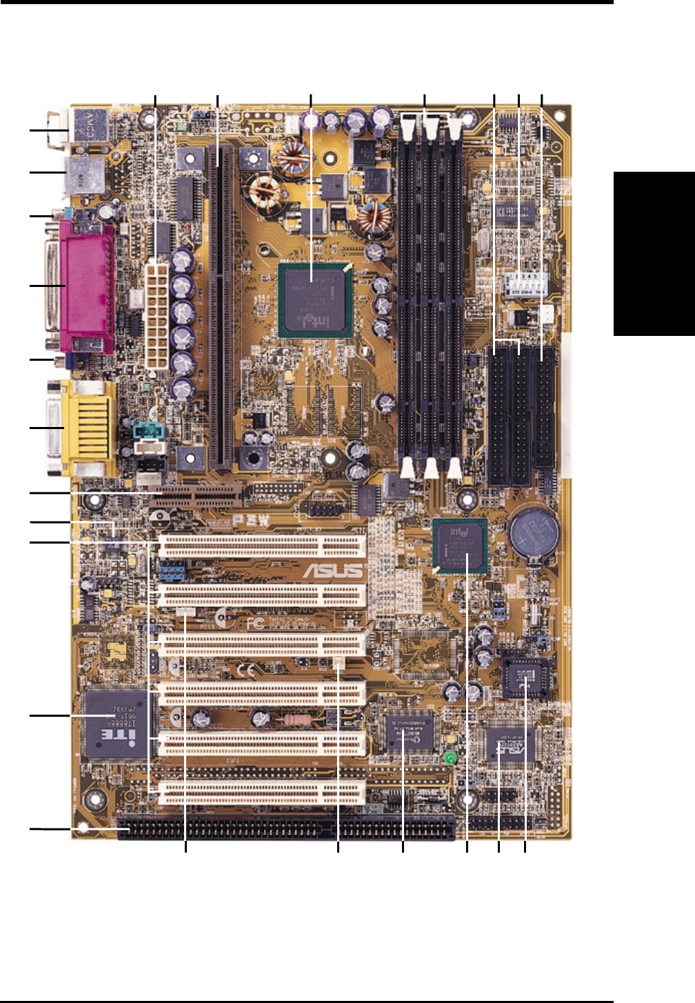
2.2 Motherboard Part Definitions
The following are part descriptions for the motherboard parts shown on the next
page.
Part Definitions
2. FEATURES
ATX Power Connector for connection to an ATX power supply
SEC CPU Socket
Intel 810 (GMCH0) Integrated Graphics Chipset
Three DIMM Sockets
Primary and Secondary IDE Connectors
Feature Setting DIP Switches
Floppy Disk Drive Connector
Four Mbit Firmware Hub (programmable BIOS)
ASUS ASIC with Integrated Hardware Monitor
Intel I/O Controller Hub (ICH)
Low Pin Count Multi-I/O Chipset
Wake-On-Ring Connector
Wake-On-LAN Connector
One ISA Slot
PCI to ISA Bridge
Six PCI Slots
AC’97 V2.1 Compliant Audio CODEC
Audio Modem Riser (AMR) Connector
Joystick, MIDI, Line Out, Line In, Microphone In Connectors
VGA Monitor Output Connector
Parallel Connector
Serial COM1 Connector
USB Connectors
PS/2 Mouse, PS/2 Keyboard Connectors
1
2
3
4
5
6
7
8
9
10
11
12
13
14
15
16
17
18
19
20
21
22
23
24
ASUS P3W User’s Manual 13
2.3 Motherboard Part Locations
2. FEATURES
2. FEATURES
Part Locations
541
23
21
19
18
16
20
15
22
24
911
12
14
6 72
17
8
3
1013
14 ASUS P3W User’s Manual
3. HARDWARE SETUP
Motherboard Layout
3. H/W SETUP
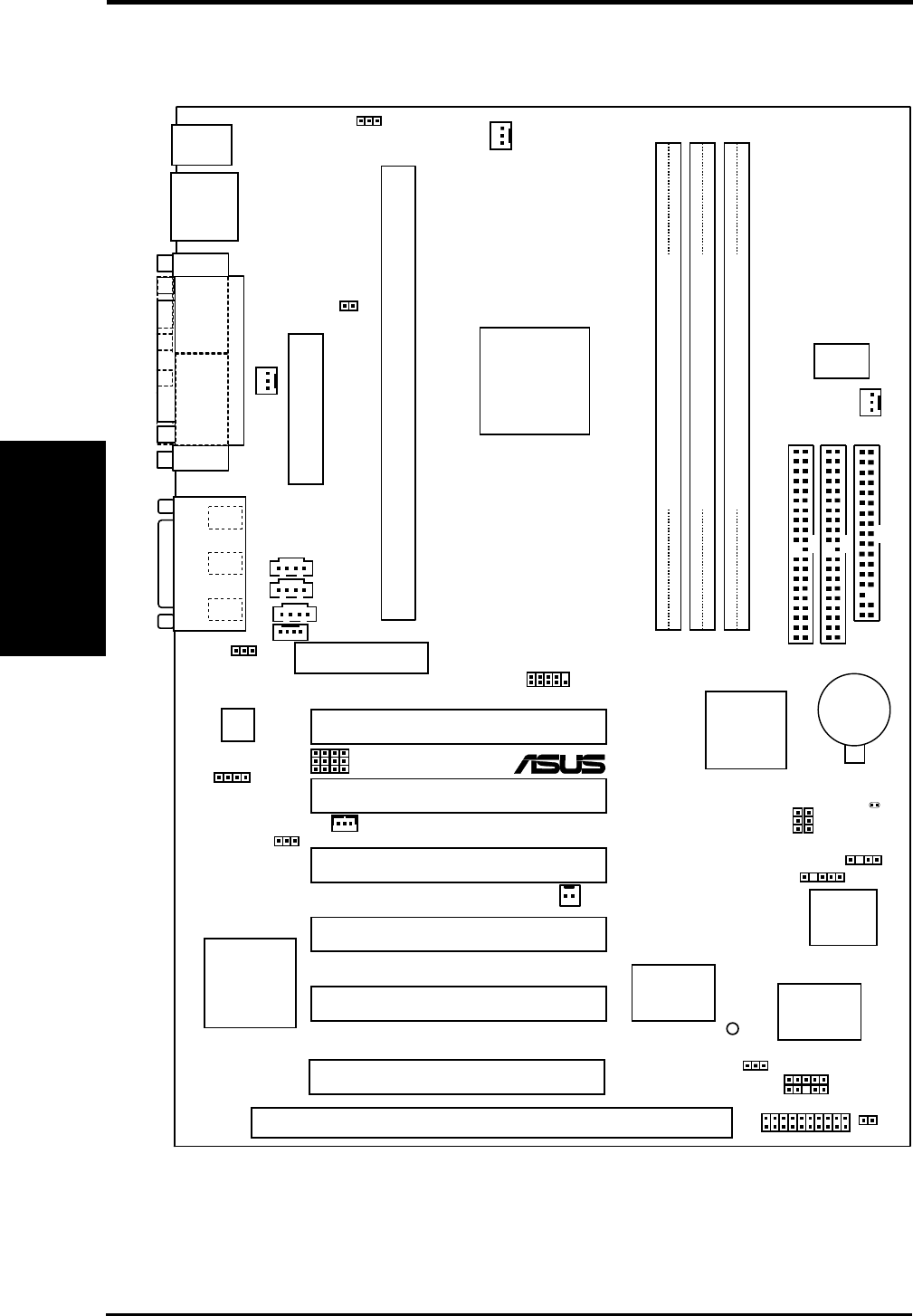
3.1 Motherboard Layout
COM1
PARALLEL PORT
VGA
PS/2
T: Mouse
B: Keyboard
CPU_FAN
Intel 810
Graphics &
Memory
Controller Hub
(GMCH0)
01
DIMM1 (64/72 bit, 168-pin module)
0 1
PWR_FAN
WOR
WOL_CON CHASIS
(ACHA)
VIDEO
MODEM
GAME_AUDIO
Mic
In
Line
Out
Line
In
CHA_FAN
CD1
AUX
SMB
PCI1
PCI2
PCI4
PCI3
PANEL
IDELED
FLOPPY
SECONDARY
IDE
PRIMARY
IDE
ISA Slot
ATX Power Connector
IR
CLRTC
Intel I/O
Controller
Hub (ICH)
01
DIMM2 (64/72 bit, 168-pin module)
2 3
01
DIMM3 (64/72 bit, 168-pin module)
3 2
CR2032 3V
Lithium Cell
CMOS Power
Row
DIP
Switches
PCI5
INT
MIC
COM2
SPEAKER
(SPKR)
Audio Modem Riser
(AMR)
T: USB1
B:USB
2
Multi-I/O
®
P3W
4Mbit
Firmware
Hub
ASUS
ASIC
with Hardware
Monitor
PLED2
Audio
Codec
CODEC
PCI to ISA
Bridge
PCI6
JEN
VIO
SAFE_MD
NO_REBOOT
Slot1
JTPWR
PCI3VSEL

ASUS P3W User’s Manual 15
3. HARDWARE SETUP
Layout Contents
3. H/W SETUP
3.2 Layout Contents
Motherboard Settings
1) JEN p.18 JumperFree™ Mode Setting (Enable/Disable)
2) CODEC p.19 Onboard Audio CODEC Setting (Enable/Disable)
3) SAFE_MD p.20 Safe Mode Setting (Normal/Safe Mode)
4) NO_REBOOT p.20 Automatic Timeout Reboot Setting (Normal/No Reboot)
5) PCI3VSEL p.21 PCI 3 Volt Setting (Normal/STB)
6) VIO p.21 I/O Voltage Setting (Normal/+3.66V)
7) SW2-6 (DSW) p.22 CPU External Clock (Bus) Frequency Setting
Expansion Slots
1) DIMM1, DIMM2, DIMM3 p.25 168-Pin DIMM Memory Support
2) CPU Slot 1 p.26 Central Processing Unit (CPU) Socket
3) ISA p.33 16-bit ISA Bus Expansion Slots
4) PCI1, 2, 3, 4, 5, 6 p.33 32-bit PCI Bus Expansion Slots
5) AMR p.34 Audio Modem Riser Slot
Connectors
1) PS2KBMS p.35 PS/2 Mouse Connector (6-pin female)
2) PS2KBMS p.35 PS/2 Keyboard Connector (6-pin female)
3) USB p.36 Universal Serial Bus Port Connectors (Two 4-pin female)
4) PRINTER p.36 Parallel Port Connector (25-pin female)
5) COM1 p.36 Serial Port Connector (9-pin male)
6) VGA p.37 Monitor (VGA) Output Connector (15-pin female)
7) GAME_AUDIO p.37 Joystick/MIDI Connector (15-pin female)
8) GAME_AUDIO p.37 Audio Port Connectors (Three 1/8” female)
9) PRIMARY/SECONDARY p.38 Primary/Secondary IDE Connectors (Two 40-1 pins)
10) IDELED p.38 IDE Device Activity LED Lead (2 pins)
11) FLOPPY p.39 Floppy Drive Port Connector (34 pins)
12) CHA_, CPU_, PWR_FAN p.39 Chassis, CPU, Power Supply Fan Connectors (Three 3-pin)
13) WOL_CON p.40 Wake-On-LAN Connector (3 pins)
14) WOR p.40 Wake-On-Ring Connector (2 pins)
15) VIDEO, AUX, CD1, MODEM p.41 Internal Audio Connectors (Four 4-pins)
16) SPKR p.41 Internal Speaker Connectors (4-pins)
17) INT MIC p.42 Internal Microphone Connector (3 pins)
18) SMB p.42 SMBus Connector (5-1 pins)
19) COM2 p.43 Serial Port Header (10-1 pin male)
20) IR p.43 Infrared Module Connectors (10-1 pins)
21) ACHA p.44 Chassis Intrusion Alarm Connector (4-1 pins)

16 ASUS P3W User’s Manual
3. HARDWARE SETUP
Layout Contents
3. H/W SETUP
22) KEYLOCK (PANEL) p.45 System Power LED Lead (3-1 pins)
23) KEYLOCK (PANEL) p.45 Keyboard Lock Switch Lead (2 pins)
24) SPEAKER (PANEL) p.45 System Warning Speaker Connector (4 pins)
25) RESET (PANEL) p.45 Reset Switch Lead (2 pins)
26) PWR (PANEL) p.45 ATX Power / Soft-Off Switch Lead (2 pins)
27) SMI (PANEL) p.45 System Management Interrupt Switch Lead (2 pins)
28) LED (PANEL) p.45 System Message LED (2 pins)
29) ATXPWR p.46 ATX Power Supply Connector (20 pins)
30) JTPWR p.46 Thermal Sensor Connector (2 pins)

ASUS P3W User’s Manual 17
3. HARDWARE SETUP
Motherboard Settings
3. H/W SETUP
3.3 Hardware Setup Procedure
Before using your computer, you must complete the following steps:
•Check Motherboard Settings
•Install Memory Modules
•Install the Central Processing Unit (CPU)
•Install Expansion Cards
•Connect Ribbon Cables, Panel Wires, and Power Supply
3.4 Motherboard Settings
This section explains in detail how to change your motherboard’s function settings
through the use of switches and/or jumpers.
WARNING! Computer motherboards and expansion cards contain very delicate
Integrated Circuit (IC) chips. To protect them against damage from static electric-
ity, you should follow some precautions whenever you work on your computer.
1. Unplug your computer when working on the inside.
2. Use a grounded wrist strap before handling computer components. If you do
not have one, touch both of your hands to a safely grounded object or to a metal
object, such as the power supply case.
3. Hold components by the edges and try not to touch the IC chips, leads or con-
nectors, or other components.
4. Place components on a grounded antistatic pad or on the bag that came with the
component whenever the components are separated from the system.
18 ASUS P3W User’s Manual
3. HARDWARE SETUP
Motherboard Settings
3. H/W SETUP
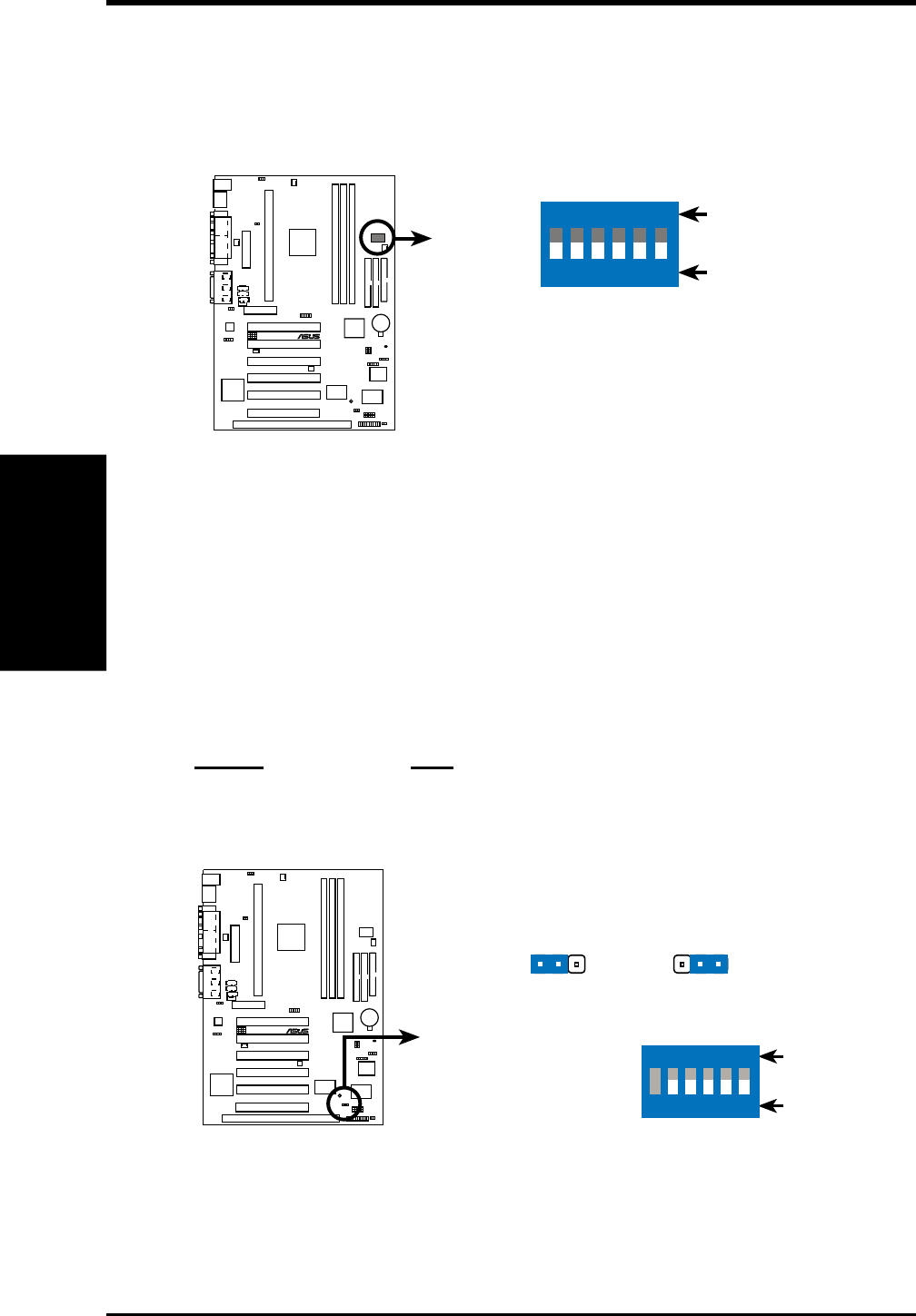
Motherboard Feature Settings (DIP Switches–DSW)
Some of the motherboard’s onboard functions are adjusted through the DIP switches.
The white block represents the switch’s position. The example below shows all the
switches in the OFF position.
10 10 1
®
P3W
1. (Reserved)
2. Frequency Selection
3. Frequency Selection
4. Frequency Selection
5. Frequency Selection
6. Frequency Selection
P3W DIP Switches
DSW
OFF
ON
ON
123456
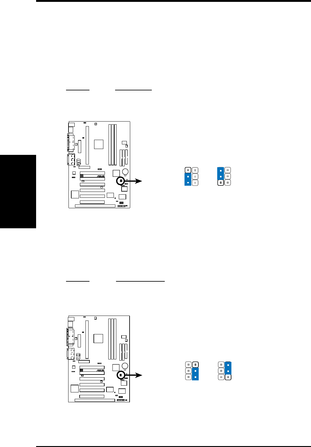
1) JumperFree™ Mode Setting (JEN)
This jumper allows you to enable or disable the JumperFree™ mode. The
JumperFree™ mode allows processor settings to be made through the BIOS
setup (see 4.4 Advanced Menu).
NOTE: For JumperFree™ mode, DIP switches 2-6 must be set to OFF.
Setting JEN
Disable (Jumper) [1-2]
Enable (JumperFree) [2-3] (default)
P3W Jumper Mode Setting
Jumper JumperFree
(default)
123 123
JEN
DSW
OFF
ON
ON
123456
10 10 1
®
P3W
ASUS P3W User’s Manual 19
3. HARDWARE SETUP
Motherboard Settings
3. H/W SETUP
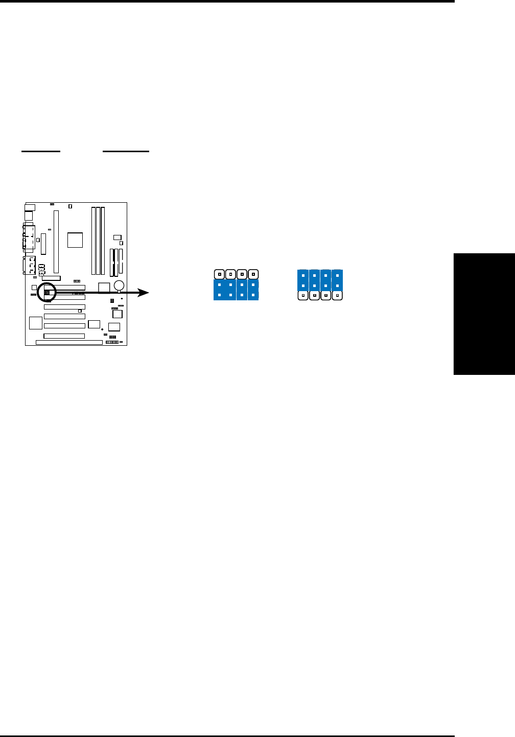
2) Onboard Audio CODEC Setting (CODEC)
The onboard audio CODEC may be enabled or disabled using all of these jump-
ers. Disable the onboard audio CODEC if you are using an ISA or PCI audio
card on any of the expansion slots or a primary AMR on the AMR slot (see AMR
Slot later in this section). If using an ISA or PCI audio expansion card, On-
board AC’97 Audio Controller in 4.4.2 I/O Device Configuration must also
be disabled.
Setting CODEC
Enable [1-2] [1-2] [1-2] [1-2] (default)
Disable [2-3] [2-3] [2-3] [2-3]
P3W Audio Codec Setting
DisableEnable
(default)
1
2
3
1
2
3
SPK
ADN#
AUD_EN1
AUD_EN2
SPK
ADN#
AUD_EN1
AUD_EN2
10 10 1
®
P3W
20 ASUS P3W User’s Manual
3. HARDWARE SETUP
Motherboard Settings
3. H/W SETUP
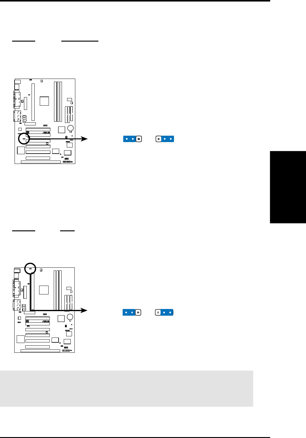
3) Safe Mode Setting (SAFE_MD)
For processors with locked frequency multiples, there is no way to exceed the
specified multiple whether through motherboard settings or BIOS setup. With
unlocked processors, exceeding the specified multiple is possible through BIOS
setup. Exceeding the specified multiple may result in hanging during bootup. If
this occurs, enable Safe Mode to force a multiple of 2 in order to enter BIOS
setup to correct the problem.
Setting SAFE_MD
Normal [1-2] (default)
Safe Mode [2-3]
10 10 1
®
P3W
P3W Safe Mode Setting
Normal
(Default) Safe Mode
1
2
3
1
2
3
SAFE_MD
4) Automatic Timeout Reboot Setting (NO_REBOOT)
The motherboard is set so that when the BIOS detects a hang (timeout) during
bootup, the motherboard will automatically reboot. If rebooting is repeating in-
effectively, set this jumper to No Reboot to disable auto-reboot.
Setting NO_REBOOT
Normal [1-2] (default)
No Reboot [2-3]
P3W Reboot Setting
Normal
(Default) No Reboot
1
2
3
1
2
3
NO_REBOOT
10 10 1
®
P3W
ASUS P3W User’s Manual 21
3. HARDWARE SETUP
Motherboard Settings
3. H/W SETUP
5) PCI 3 Volt Setting (PCI3VSEL)
This jumper allows you to select the voltage supplied to PCI devices. If you
have PCI devices that require auxiliary power, set this jumper to STB.
Setting PCI3VSEL
Normal [1-2]
Standby [2-3] (default)
P3W PCI 3Volt Selection
Normal Standby (STB)
(Default)
123 123
PCI3VSEL
10 10 1
®
P3W
6) I/O Voltage Setting (VIO)
This jumper allows you to select the voltage supplied to the DRAM, chipset,
PCI, and the CPU’s I/O buffer. The default voltage should be used unless pro-
cessor overclocking requires a higher voltage.
Setting VIO
Normal [1-2] (default)
3.66V [2-3]
10 10 1
®
P3W
P3W I/O Voltage Setting
Normal
(default) 3.66Volt
123 123
VIO
WARNING! Using a higher voltage may help when overclocking but may result
in the shortening of your computer component’s life. It is strongly recommended
that you leave this setting on its default.
22 ASUS P3W User’s Manual
3. HARDWARE SETUP
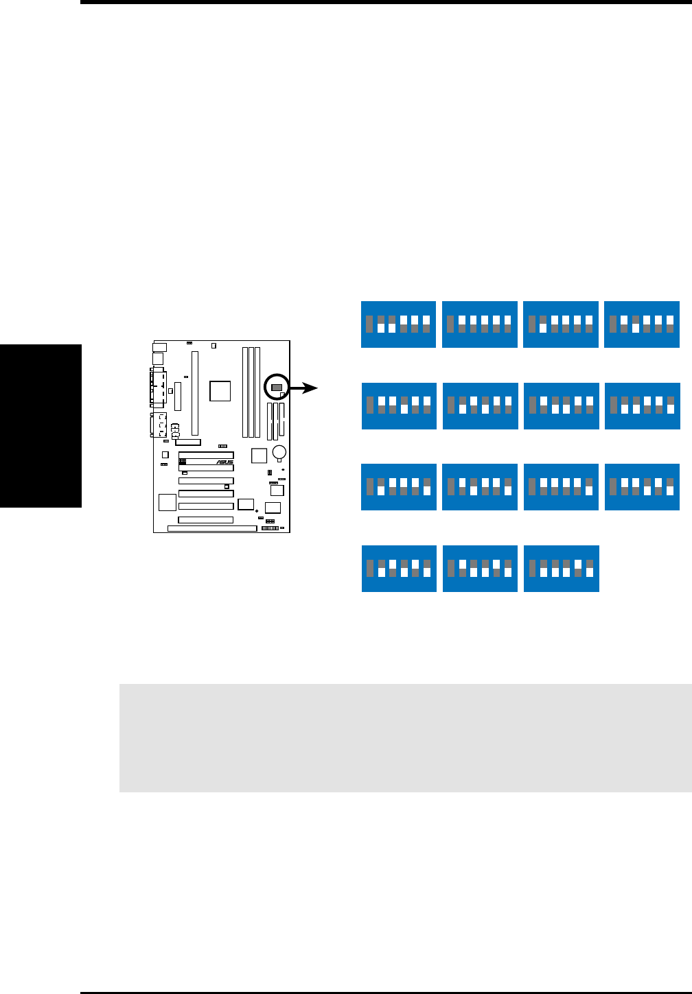
7) CPU External Frequency Setting (DSW–SW2-6)
This option tells the clock generator what frequency to send to the CPU, DRAM,
and the PCI bus. This allows the selection of the CPU’s External frequency. The
CPU External Frequency multiplied by the Frequency Multiple equals the CPU’s
Internal frequency (the advertised CPU speed). NOTE: You may set the memory
speed independently from the CPU External Frequency. Depending on your
memory type, select the appropriate “SDRAM” speed along with the appropri-
ate “CPU” speed.
IMPORTANT: When JumperFree mode is enabled, use BIOS setup in place of
these switches (see CPU Speed in 4.4 Advanced Menu).
NOTE: For JumperFree mode, DIP switches 2-6 must be set to OFF.
10 10 1
®
P3W
P3W CPU External Clock
(BUS) Frequency Selection
DSW
CPU
SDRAM →
→69MHz
103MHz
66MHz
100MHz
CPU
SDRAM →
→75MHz
112MHz
72MHz
108MHz
CPU
SDRAM →
→109MHz
109MHz
104MHz
104MHz
ON
123456
ON
123456
ON
123456
ON
123456
ON
123456
ON
123456
CPU
SDRAM →
→133MHz
133MHz
123MHz
123MHz
ON
123456
ON
123456
71MHz
106MHz
100MHz
100MHz
117MHz
117MHz
ON
123456
ON
123456
ON
123456
70MHz
105MHz
76MHz
114MHz
111MHz
111MHz
ON
123456
ON
123456
ON
123456
142MHz
142MHz
ON
123456
WARNING! CPU frequencies other than 66MHz and 100MHz are not guaran-
teed to be stable. Premature wearing of the processor may result when
overclocking. Be sure that the DIMM you use can handle the specified SDRAM
MHz or else bootup will not be possible.
Motherboard Settings
3. H/W SETUP

ASUS P3W User’s Manual 23
3. HARDWARE SETUP
External Frequency Table
The following table is for use by experienced motherboard installers only. Overclock-
ing can result in system instability or even shortening the life of the processor.
CPU SDRAM PCI Frequency Selection Switches
(MHz)(MHz)(MHz) 23456
69.00 103.50 34.50 [ON] [ON] [ON] [ON] [ON]
70.00 105.00 35.00 [OFF] [ON] [ON] [ON] [ON]
71.00 106.50 35.50 [ON] [OFF] [ON] [ON] [ON]
66.82 100.23 33.41 [OFF] [OFF] [ON] [ON] [ON]
72.00 108.00 36.00 [ON] [ON] [OFF] [ON] [ON]
75.00 112.50 37.50 [OFF] [ON] [OFF] [ON] [ON]
76.60 114.90 38.40 [ON] [OFF] [OFF] [ON] [ON]
111.77 111.77 37.26 [ON] [ON] [ON] [ON] [OFF]
104.78 104.78 34.93 [OFF] [ON] [ON] [ON] [OFF]
109.51 109.51 36.50 [ON] [OFF] [ON] [ON] [OFF]
100.74 100.74 33.57 [OFF] [OFF] [ON] [ON] [OFF]
117.00 117.00 39.00 [ON] [ON] [OFF] [ON] [OFF]
123.75 123.75 41.25 [OFF] [ON] [OFF] [ON] [OFF]
133.33 133.33 44.44 [ON] [OFF] [OFF] [ON] [OFF]
142.50 142.50 47.50 [OFF] [OFF] [OFF] [ON] [OFF]
NOTE: The PCI clock is equal to 1/3 the speed of the SDRAM. PCI’s specification
allows for up to 33MHz, therefore using PC100-compliant DIMM and setting
SDRAM to about 100MHz is recommended. For updated processor settings, visit
ASUS’s web site (see ASUS CONTACT INFORMATION)
Motherboard Settings
3. H/W SETUP

24 ASUS P3W User’s Manual
3. HARDWARE SETUP
System Memory
3. H/W SETUP
3.5.1 General DIMM Notes
• ASUS motherboards support SPD (Serial Presence Detect) DIMMs. This is the
memory of choice for best performance vs. stability.
• SDRAM chips are generally thinner with higher pin density than EDO (Extended
Data Output) chips.
• BIOS shows SDRAM memory on bootup screen.
• Single-sided DIMMs come in 16, 32, 64,128MB; double-sided come in 32, 64,
128, 256MB.
3.5 System Memory (DIMM)
NOTE: No hardware or BIOS setup is required after adding or removing memory.
This motherboard uses only Dual Inline Memory Modules (DIMMs). Sockets are
available for 3.3Volt (power level) unbuffered Synchronous Dynamic Random Ac-
cess Memory (SDRAM) of 16, 32, 64, 128MB, or 256MB.
This chipset does not support ECC. However, ECC memory modules may still be
used, but the ECC function will not be available.
Memory speed setup is recommended through SDRAM Configuration in 4.4.1
Chip Configuration.
Install memory in any combination as follows:
Location 168-pin DIMM SDRAM Total Memory
DIMM1 Single-Sided
(Rows 0&1) Double-Sided x1
DIMM2 Single-Sided (must be occupied before DIMM3)
(Rows 2&3) Double-Sided (DIMM3 must be empty) x1
DIMM3 Single-Sided (DIMM2 must be single-sided)
(Rows 3&2) (Double-Sided DIMM cannot be used here!) x1
(must be same or half DIMM2 memory size)
Total System Memory (Max 512MB) =
ASUS P3W User’s Manual 25
3. HARDWARE SETUP
System Memory
3. H/W SETUP
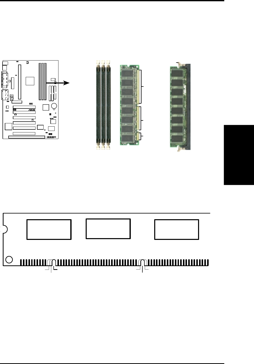
3.5.2 DIMM Installation
Insert the module(s) as shown. Because the number of pins are different on either
side of the breaks, the module will only fit in the orientation shown. DIMMs are
longer and have different pin contact on each side and therefore have a higher pin
density. SIMMs have the same pin contact on both sides.
10 10 1
®
P3W
P3W 168-Pin DIMM Sockets
Lock
FRONT
20 Pins
60 Pins
88 Pins
The DIMMs must be 3.3V Unbuffered for this motherboard. To determine the DIMM
type, check the notches on the DIMMs (see figure below).
168-Pin DIMM Notch Key Definitions (3.3V)
DRAM Key Position Voltage Key Position
Unbuffered
RFU
Buffered Reserved
3.3V
5.0V
The notches on the DIMM module will shift between left, center, or right to identify
the type and also to prevent the wrong type from being inserted into the DIMM slot
on the motherboard. You must ask your retailer the correct DIMM type before pur-
chasing. This motherboard supports four clock signals per DIMM slot.
26 ASUS P3W User’s Manual
3. HARDWARE SETUP
CPU
3. H/W SETUP
3.6 Central Processing Unit (CPU)
NOTE: The following pictures are provided for reference purposes only. The ap-
pearance of your retention mechanism and fan may be different from the following
examples.
Your motherboard provides a Slot 1 connector for a Pentium
®
III processor pack-
aged in a Single Edge Contact Cartridge (SECC2), a Pentium
®
II processor pack-
aged in SECC2/SECC, or a Celeron™ processor packaged in a Single Edge Proces-
sor Package (SEPP). An ASUS S370 CPU card can allow Socket 370 processors to
be used on any ASUS motherboard with the Slot 1 connector (See 7.2 S370 Series
CPU Card for instructions on using this card).
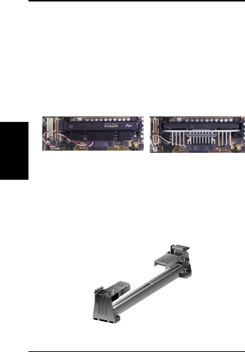
3.6.1 Universal Retention Mechanism
Your motherboard comes preinstalled with a Universal Retention Mechanism (URM).
The URM supports Pentium III / II and Celeron processors.
Universal Retention Mechanism (URM)
Pentium II processor packaged in an SECC with
heatsink and fan (top view) Pentium III (in an SECC2) with heatsink and fan
NOTE: The SEPP fan (for Celeron processors) is
similar to SECC2 fan except that the clamping
design is different.
ASUS P3W User’s Manual 27
3. HARDWARE SETUP
CPU
3. H/W SETUP
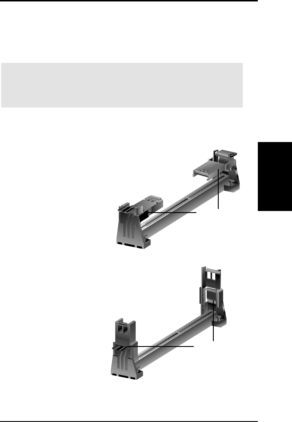
The URM is now ready for the installation of your processor.
3.6.3 Installing the Processor
Unlocked Folding Support
To unlock the support arms, simply flip
them up to an upright position.
Locked Folding Support
1. Unlock the URM’s Folding Support
Arms: The folding support arms of
the URM are locked when shipped.
3.6.2 Heatsinks
The recommended heatsinks (see section on recommended heatsinks for Pentium
III / II processors for more information) for the boxed Pentium III / II and Celeron
processors are those with three-pin fans that can be connected to the fan connectors
on the motherboard.
WARNING! Be sure that there is sufficient air circulation across the processor’s
heatsink by regularly checking that your CPU fan is working. Without sufficient
circulation, the processor could overheat and damage both the processor and the
motherboard. You may install an auxiliary chassis fan, if necessary.
28 ASUS P3W User’s Manual
3. HARDWARE SETUP
CPU
3. H/W SETUP
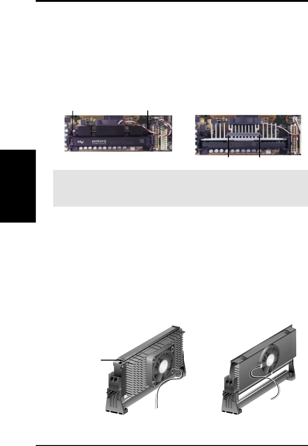
3. Insert the SECC2/SECC/SEPP
SECC with Pentium
®
II only: Push the SECC’s two locks inward until you hear
a click (the picture in step 2 shows the locks in the outward position and inward in
the picture below).
With the heatsink facing the motherboard’s chipset, push the SECC2, SECC, or
SEPP gently but firmly into the Slot 1 connector until it is fully inserted.
SECC2/SEPP
Push lock inward
SECC
CPU fan cable to
fan connector CPU fan cable to
fan connector
2. Attach the Heatsink
NOTE: If provided, you should follow the heatsink attachment instructions
that came with your heatsink or processor. The following steps are provided
only as a general guide and may not reflect those for your heatsink.
Using SECC fan with Pentium
®
II
Push the two lock arms one direction to
clamp the heatsink onto the processor
and the other direction to release.
Using SECC2 fan with Pentium
®
III
Insert the four heatsink’s pins through
the holes of the SECC2. Place the metal
clip on the ends of the pins and slide
until it locks into place.
WARNING! Make sure the heatsink is mounted tightly against the SECC2, SECC,
or SEPP; otherwise, the CPU will overheat. You may install an auxiliary fan to
provide adequate circulation across the processor’s passive heatsink.
NOTE: The SEPP heatsink and fan (for Intel Celeron processors) is similar to
the SECC2 heatsink and fan except that the clamping design is different.
Four Pins and metal clip
Lock Arm Lock Arm

ASUS P3W User’s Manual 29
3. HARDWARE SETUP
CPU
3. H/W SETUP
4. Secure the SECC2/SECC/SEPP
Secure the SECC2/SECC/SEPP in place by pushing the SECC2/SECC/SEPP
until it is firmly seated on the Slot 1 connector.
SECC with Pentium
®
II only: The SECC locks should be outward when se-
cured so that the lock shows through the retention mechanism’s lock holes.
SECC SECC2/SEPP
CPU fan cable to
fan connector
CPU fan
cable to fan
connector
Lock hole
Lock hole
3.6.4 Recommended Heatsinks for Slot 1 Processors
The recommended heatsinks for the Slot 1 processors are those with three-pin fans,
such as the ASUS Smart Fan, that can be connected to the motherboard’s CPU fan
connector. These heatsinks dissipate heat more efficiently and with an optional hard-
ware monitor, they can monitor the fan’s RPM and use the alert function with the
Intel LANDesk Client Manager (LDCM) or the ASUS PC Probe software.
SECC Heatsink & Fan SECC2 Heatsink & Fan
NOTE: The SEPP heatsink and fan (for Intel Celeron processors) is similar to the
SECC2 heatsink and fan except that the clamping design is different.

30 ASUS P3W User’s Manual
3. HARDWARE SETUP
CPU
3. H/W SETUP
3.6.5 Precautions
Operating a processor at temperatures above its maximum specified operating tem-
perature will shorten the processor lifetime and may cause unreliable operation. To
prevent system overheat and/or damage, it is important to have accurate tempera-
ture readings of the processor core (the main source of power dissipation) for sys-
tem thermal management. Included inside Pentium III, Pentium II (Deschutes), and
PPGA370 Celeron processors is a thermal sensor that is connected to the internal
thermal diode.
Unlike other motherboards, this motherboard was designed to acquire thermal data
directly from the processor thermal diode. Therefore, the CPU temperature reported
may be higher than those from motherboards that take readings from thermal sen-
sors external to the processor. This is not a cause for alarm. If, however, the BIOS
and/or your hardware monitoring program is reporting a CPU temperature above
the threshold, check the following:
1. An Intel recommended fan heatsink is used.
2. Good quality thermal interface material is used.
3. The heatsink is correctly installed onto the processor with a strong retention clip.
4. There is no visible gap between the processor die and heatsink.
Example of an incorrectly installed retention clip
The thermal interface material
should be continuous with no
through-holes or debris.
Example of a correctly installed retention clip

ASUS P3W User’s Manual 31
3. HARDWARE SETUP
Expansion Cards
3. H/W SETUP
3.7 Expansion Cards
3.7.1 Expansion Card Installation Procedure
1. Read the documentation for your expansion card and make any necessary hard-
ware or software settings for your expansion card, such as jumpers.
2. Remove your computer system’s cover and the bracket plate on the slot you
intend to use. Keep the bracket for possible future use.
3. Carefully align the card’s connectors and press firmly.
4. Secure the card on the slot with the screw you removed above.
5. Replace the computer system’s cover.
6. Set up the BIOS if necessary
(such as IRQ xx Used By ISA: Yes in 4.4.3 PCI Configuration)
7. Install the necessary software drivers for your expansion card.
WARNING! Unplug your power supply when adding or removing expansion
cards or other system components. Failure to do so may cause severe damage to
both your motherboard and expansion cards.

32 ASUS P3W User’s Manual
3. HARDWARE SETUP
3.7.2 Assigning IRQs for Expansion Cards
Some expansion cards need an IRQ to operate. Generally, an IRQ must be exclu-
sively assigned to one use. In a standard design, there are 16 IRQs available but
most of them are already in use, leaving 6 IRQs free for expansion cards. If your
motherboard has PCI audio onboard, an additional IRQ will be used. If your moth-
erboard also has MIDI enabled, another IRQ will be used, leaving 4 IRQs free.
The following table lists the default IRQ assignments for standard PC devices. Use
this table when configuring your system and for resolving IRQ conflicts.
Standard Interrupt Assignments
IRQ Priority Standard Function
0 1 System Timer
1 2 Keyboard Controller
2 N/A Programmable Interrupt
3* 11 Communications Port (COM2)
4* 12 Communications Port (COM1)
5* 13
6 14 Floppy Disk Controller
7* 15 Printer Port (LPT1)
8 3 System CMOS/Real Time Clock
9* 4 ACPI Mode when enabled
10* 5 IRQ Holder for PCI Steering
11* 6 IRQ Holder for PCI Steering
12* 7 PS/2 Compatible Mouse Port
13 8 Numeric Data Processor
14* 9 Primary IDE Channel
15* 10 Secondary IDE Channel
*These IRQs are usually available for ISA or PCI devices.
Expansion Cards
3. H/W SETUP

ASUS P3W User’s Manual 33
3. HARDWARE SETUP
IMPORTANT: If using PCI cards on shared slots, make sure that the drivers
support “Share IRQ” or that the cards do not need IRQ assignments. Conflicts
will arise between the two PCI groups that will make the system unstable or
cards inoperable.
Both ISA and PCI expansion cards may require IRQs. System IRQs are available to
cards installed in the ISA expansion bus first, then any remaining IRQs are available
to PCI cards. Currently, there are two types of ISA cards.
The original ISA expansion card design, now referred to as “Legacy” ISA cards,
requires that you configure the card’s jumpers manually and then install it in any
available slot on the ISA bus. To see a map of your used and free IRQs in Windows
98, the Control Panel icon in My Computer, contains a System icon, which gives
you a Device Manager tab. Double-clicking on a specific hardware device gives
you the Resources tab which shows the Interrupt number and address. Double-click
Computer to see all the interrupts and addresses for your system. Make sure that no
two devices use the same IRQ or your computer will experience problems when
those two devices are in use at the same time.
To simplify this process, this motherboard complies with the Plug and Play (PnP)
specification which was developed to allow automatic system configuration when-
ever a PnP-compliant card is added to the system. For PnP cards, IRQs are assigned
automatically from those available.
If the system has both Legacy and PnP ISA cards installed, IRQs are assigned to
PNP cards from those not used by Legacy cards. The PCI and PNP configuration of
the BIOS setup utility can be used to indicate which IRQs are being used by Legacy
cards. For older Legacy cards that does not work with the BIOS, you can contact
your vendor for an ISA Configuration Utility.
An IRQ number is automatically assigned to PCI expansion cards after those used
by Legacy and PnP ISA cards. In the PCI bus design, the BIOS automatically as-
signs an IRQ to a PCI slot that has a card in it that requires an IRQ. To install a PCI
card, you need to set something called the INT (interrupt) assignment. Since all the
PCI slots on this motherboard use an INTA #, be sure that the jumpers on your PCI
cards are set to INT A.
Interrupt Request Table INT-A INT-B INT-C INT-D
PCI slot 1 shared -- -- --
PCI slot 2 -- shared -- --
PCI slot 3 -- -- shared --
PCI slot 4 -- -- -- shared
PCI slot 5 shared -- -- --
PCI slot 6 -- -- shared --
Onboard VGA shared ---- -- --
Onboard audio/AMR/SMBus -- shared -- --
USB -- -- -- shared
Expansion Cards
3. H/W SETUP
34 ASUS P3W User’s Manual
3. HARDWARE SETUP
3.7.3 Assigning DMA Channels for ISA Cards
Some ISA cards, both legacy and PnP, may also need to use a DMA (Direct Memory
Access) channel. DMA assignments for this motherboard are handled the same way
as the IRQ assignment process described earlier. To select a DMA channel, see PCI/
PNP ISA DMA Resource Exclusion in 4.4.3 PCI Configuration. NOTE: The on-
board audio by default uses DMA1.
IMPORTANT: To avoid conflicts, reserve the necessary IRQs and DMAs for
legacy ISA cards (see PCI/PNP ISA IRQ Resource Exclusion and PCI/PNP
DMA IRQ Resource Exclusion in 4.4.3 PCI Configuration). Choose Yes in
IRQ xx Used By ISA and DMA x Used By ISA for those IRQs and DMAs you
want to reserve).
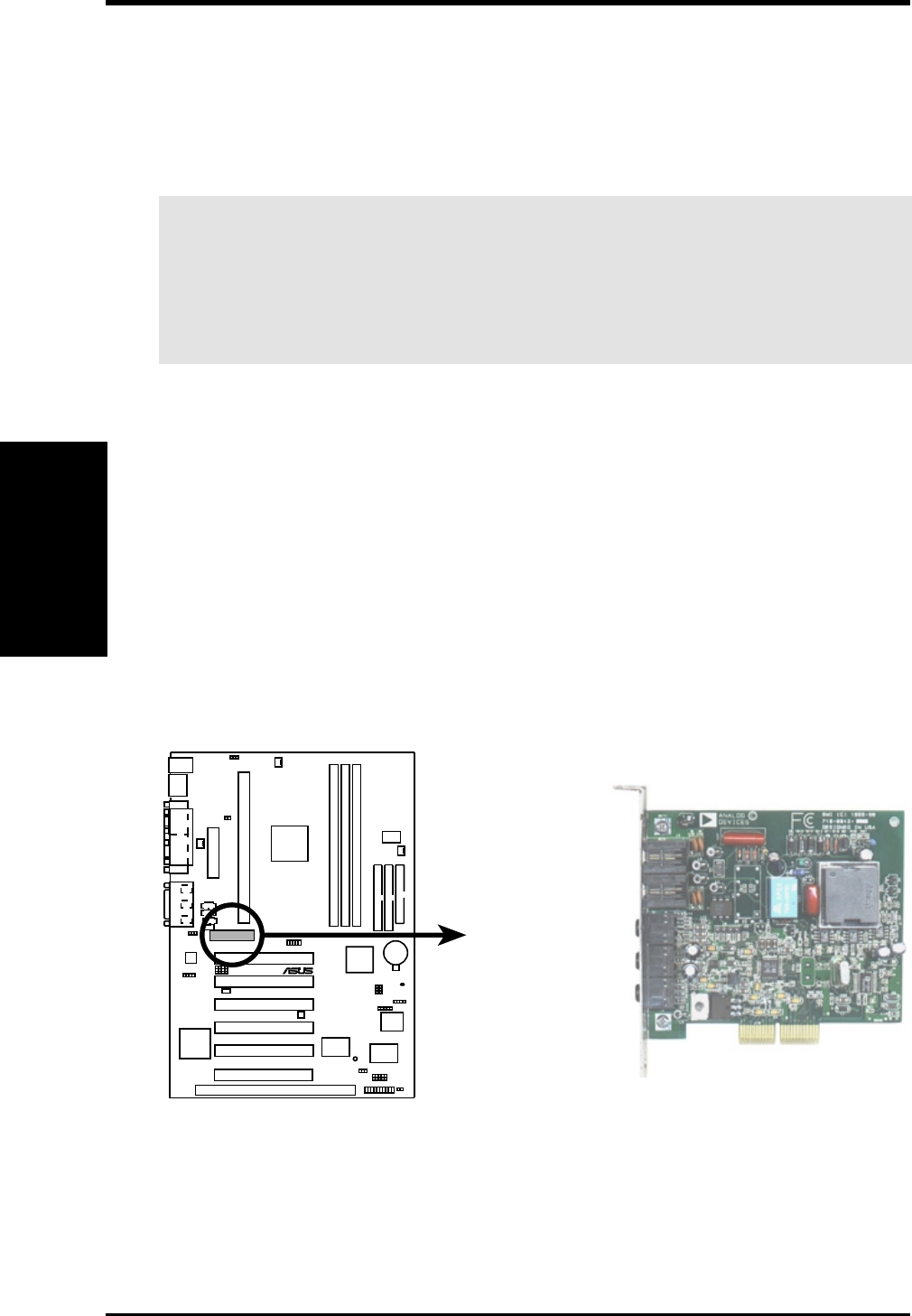
3.7.4 Audio Modem Riser (AMR) Slot
This connector supports a specially designed audio and/or modem card called an
AMR. Main processing is done through software and controlled by the motherboard’s
Intel I/O Controller Hub (ICH). This provides an upgradeable audio and/or modem
solution at an incredibly low cost. There are two types of AMR, one defined as
primary and another defined as secondary. This motherboard uses the primary chan-
nel so that a secondary AMR can coexist without the need to disable the onboard
CODEC. The motherboard’s onboard CODEC must be disabled when using a pri-
mary AMR.
NOTE: An AMR is not included with this motherboard.
10 10 1
®
P3W
P3W Audio Modem Riser (AMR) Connector
Expansion Cards
3. H/W SETUP
3.8 External Connectors
WARNING! Some pins are used for connectors or power sources. These are
clearly distinguished from jumpers in the Motherboard Layout. Placing jumper
caps over these connector pins will cause damage to your motherboard.
IMPORTANT: Ribbon cables should always be connected with the red stripe to
Pin 1 on the connectors. Pin 1 is usually on the side closest to the power connec-
tor on hard drives and CD-ROM drives, but may be on the opposite side on
floppy disk drives. Check the connectors before installation because there may
be exceptions. IDE ribbon cables must be less than 46 cm (18 in.), with the
second drive connector no more than 15 cm (6 in.) from the first connector.
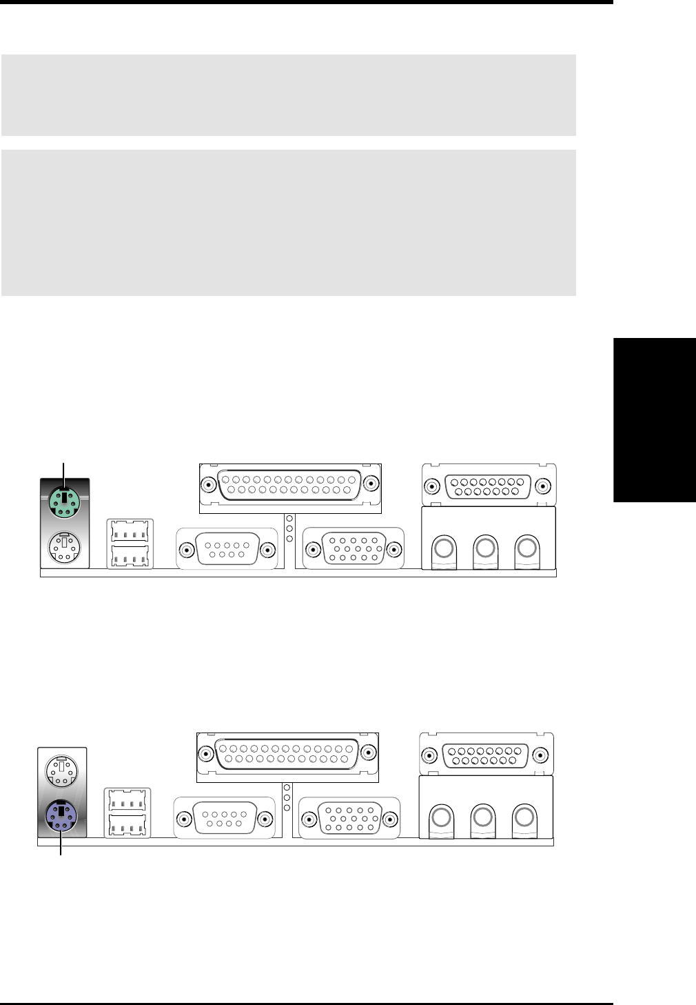
1) PS/2 Mouse Connector (Green 6-pin PS2KBMS)
The system will direct IRQ12 to the PS/2 mouse if one is detected. If one is not
detected, expansion cards can use IRQ12. See PS/2 Mouse Function Control
in 4.4 Advanced Menu.
PS/2 Mouse (6-pin female)
2) PS/2 Keyboard Connector (Purple 6-pin PS2KBMS)
This connection is for a standard keyboard using an PS/2 plug (mini DIN). This
connector will not allow standard AT size (large DIN) keyboard plugs. You
may use a DIN to mini DIN adapter on standard AT keyboards.
PS/2 Keyboard (6-pin female)
ASUS P3W User’s Manual 35
3. HARDWARE SETUP
Connectors
3. H/W SETUP
36 ASUS P3W User’s Manual
Connectors
3. H/W SETUP
3. HARDWARE SETUP
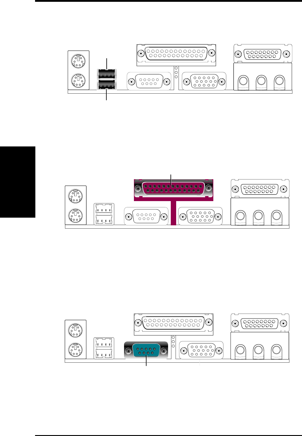
3) Universal Serial Bus Ports 1 & 2 (Two black 4-pin USB)
Two USB ports are available for connecting USB devices.
Universal Serial Bus (USB) 2
USB 1
4) Parallel Port Connector (Burgundy 25-pin PRINTER)
You can enable the parallel port and choose the IRQ through Onboard Parallel
Port (see 4.4.2 I/O Device Configuration).
NOTE: Serial printers must be connected to the serial port.
Parallel (Printer) Port (25-pin female)
5) Serial Port COM1 Connector (Teal/Turquoise 9-pin COM1)
One serial port is ready for a mouse or other serial devices. A second serial port
is available using a serial port bracket connected from the motherboard to an
expansion slot opening. See Onboard Serial Port 1 in 4.2.2 I/O Device Con-
figuration for settings.
COM 1
Serial Port (9-pin male)
ASUS P3W User’s Manual 37
3. HARDWARE SETUP
Connectors
3. H/W SETUP
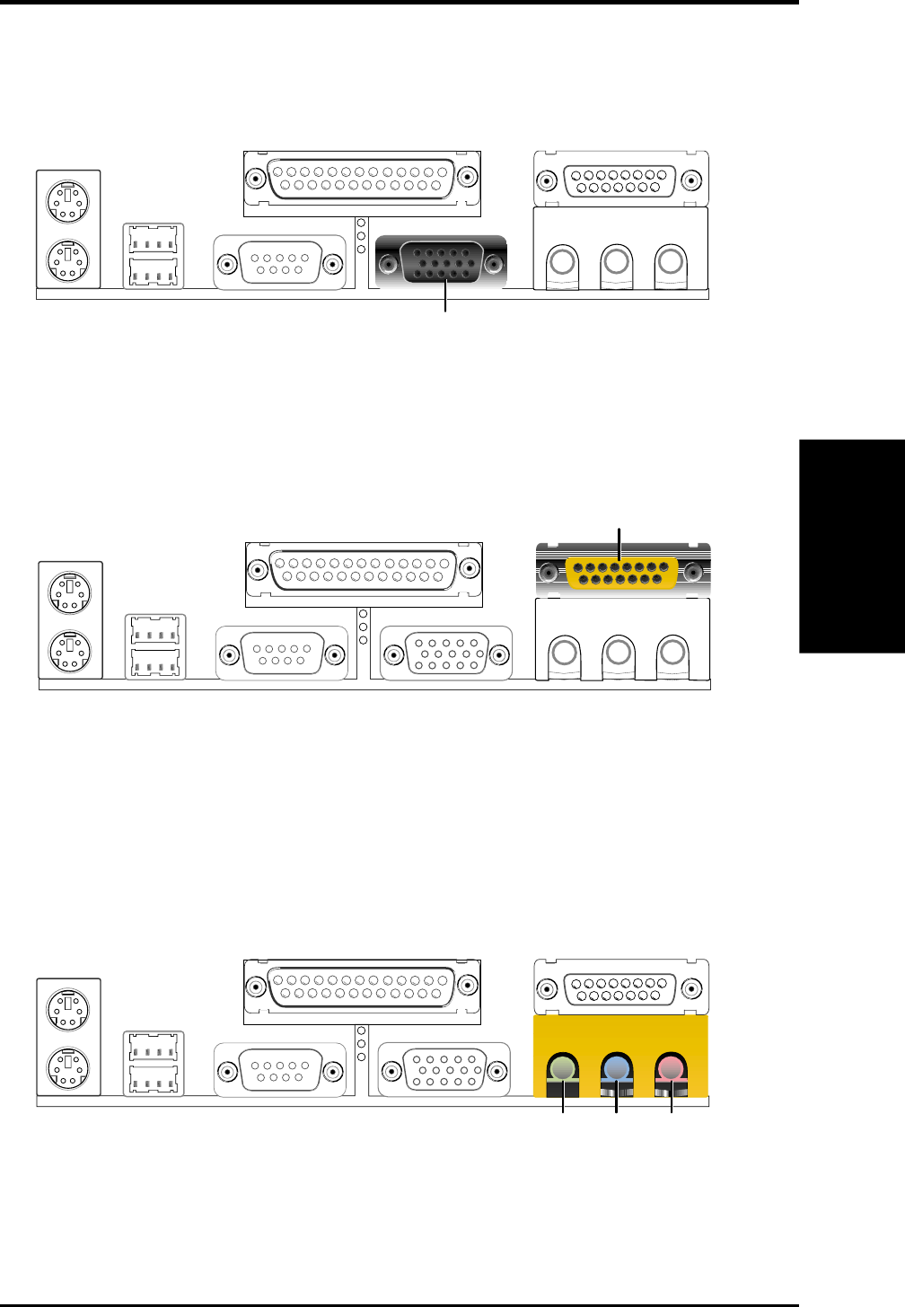
6) Monitor Output Connector (Blue 15-pin VGA)
This connector is for output to a VGA-compatible device.
7) Joystick/MIDI Connector (Gold 15-pin GAME_AUDIO)
You may connect game joysticks or game pads to this connector for playing
games. Connect MIDI devices for playing or editing professional audio.
Joystick/MIDI (15-pin female)
8) Audio Port Connectors (Three 1/8” GAME_AUDIO)
Line Out (lime) can be connected to headphones or preferably powered speak-
ers. Line In (light blue) allows tape players or other audio sources to be re-
corded by your computer or played through the Line Out (lime). Mic (pink)
allows microphones to be connected for inputting voice.
MicLine InLine Out
1/8" Stereo Audio Connectors
38 ASUS P3W User’s Manual
Connectors
3. H/W SETUP
3. HARDWARE SETUP
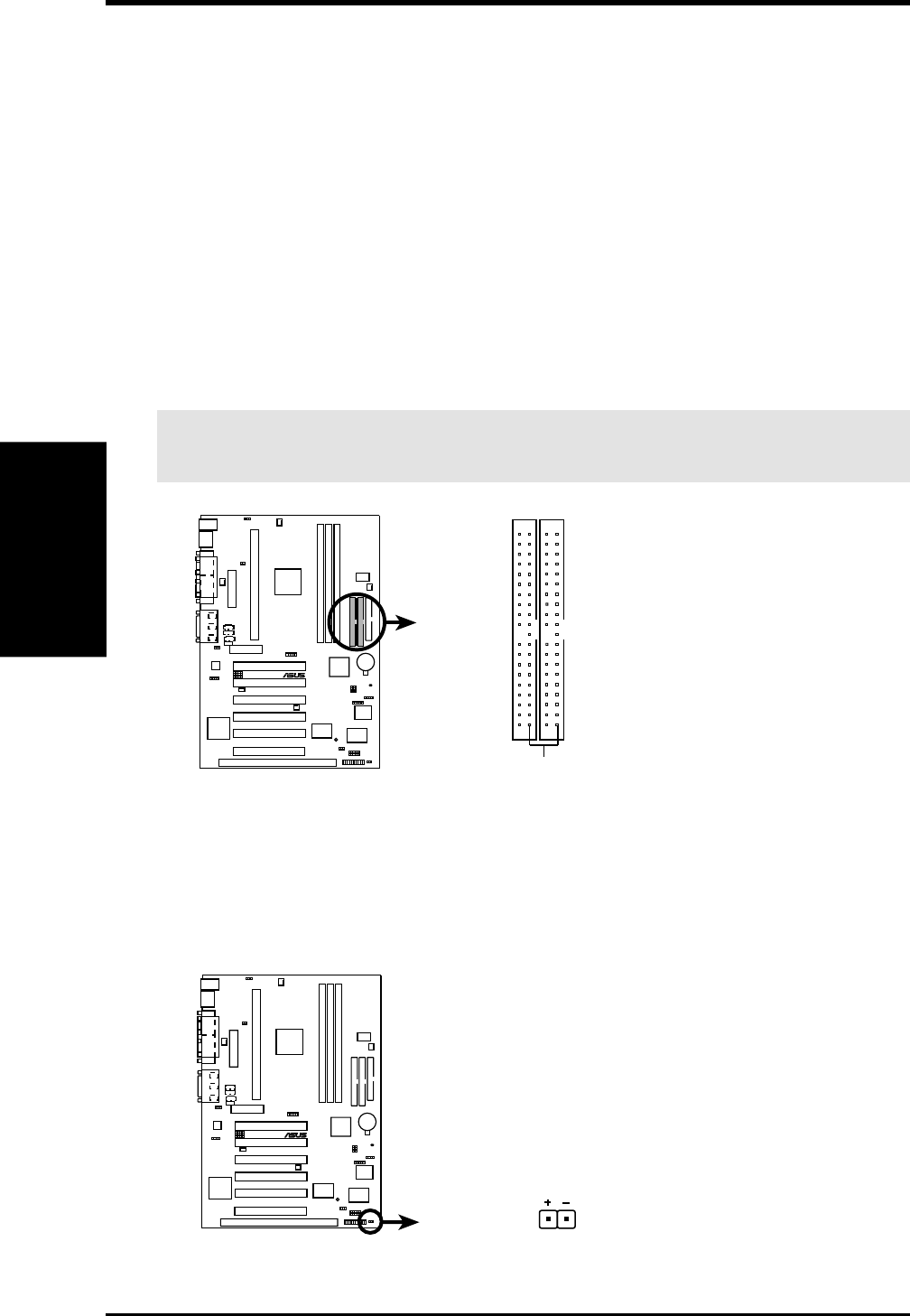
9) Primary / Secondary IDE Connectors (40-1 pin PRIMARY/SECONDARY)
These connectors support the provided IDE hard disk ribbon cable.
After connecting the single end to the board, connect the two plugs at the other
end to your hard disk(s). If you install two hard disks, you must configure the
second drive to Slave mode by setting its jumper accordingly. Refer to your hard
disk documentation for the jumper settings. BIOS now supports specific device
bootup (see Boot Sequence in 4.6 Boot Menu). (Pin 20 is removed to prevent
inserting in the wrong orientation when using ribbon cables with pin 20
plugged).
TIP: You may configure two hard disks to be both Masters with two ribbon
cables – one for the primary IDE connector and another for the secondary IDE
connector. You may install one operating system on an IDE drive and another on
a SCSI drive and select the boot disk through Boot Sequence in 4.6 Boot Menu.
IMPORTANT: UltraDMA/66 IDE devices must use an 80-conductor IDE
cable.
10 10 1
®
P3W
P3W IDE Connectors
NOTE: Orient the red markings
on the IDE ribbon cable to
PIN 1
Primary IDE Connector
Secondary IDE Connector
PIN 1
10) IDE Activity LED Lead (2-pin IDELED)
This lead supplies power to the cabinet’s IDE activity LED. Read and write
activity by devices connected to the Primary and/or Secondary IDE connectors
will cause the LED to light up.
10 10 1
®
P3W
P3W IDE Activity LED
TIP: If the case-mounted LED does not
light, try reversing the 2-pin plug.
IDELED
ASUS P3W User’s Manual 39
3. HARDWARE SETUP
Connectors
3. H/W SETUP
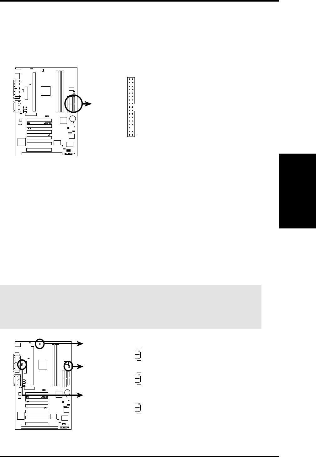
11) Floppy Disk Drive Connector (34-1pin FLOPPY)
This connector supports the provided floppy disk drive ribbon cable. After con-
necting the single end to the board, connect the two plugs on the other end to the
floppy drives. (Pin 5 is removed to prevent inserting in the wrong orienta-
tion when using ribbon cables with pin 5 plugged).
NOTE: Orient the red markings on
the floppy ribbon cable to
PIN 1
P3W Floppy Disk Drive Connector
PIN 1
10 10 1
®
P3W
12) Chassis, CPU, & Power Supply Fan Connectors (3-pin CHA_, CPU_, PWR_FAN)
These connectors support cooling fans of 350mA (4.2 Watts) or less. Orientate
the fans so that the heat sink fins allow airflow to go across the onboard heat
sink(s) instead of the expansion slots. Depending on the fan manufacturer, the
wiring and plug may be different. The red wire should be positive, while the
black should be ground. Connect the fan’s plug to the board taking into consid-
eration the polarity of the connector.
NOTE: The “Rotation” signal is to be used only by a specially designed fan with
rotation signal. The Rotations per Minute (RPM) can be monitored using ASUS PC
Probe Utility or Intel LDCM Utility (see 6. SOFTWARE REFERENCE).
WARNING! The CPU and/or motherboard will overheat if there is no airflow
across the CPU and onboard heatsinks. Damage may occur to the motherboard
and/or the CPU fan if these pins are incorrectly used. These are not jumpers,
do not place jumper caps over these pins.
10 10 1
®
P3W
P3W 12-Volt Cooling Fan Power
Chassis Fan Power
GND
Rotation
+12V
Power Supply Fan
CPU Fan Power
GND
Rotation
+12V
GND
Rotation
+12V
40 ASUS P3W User’s Manual
Connectors
3. H/W SETUP
3. HARDWARE SETUP
13) Wake-On-LAN Connector (3-pin WOL_CON)
This connector connects to a LAN card with a Wake-On-LAN output, such as
the ASUS PCI-L101 Ethernet card. The connector powers up the system when a
wakeup packet or signal is received through the LAN card.
IMPORTANT: This feature requires that Wake On LAN is set to Enabled
(see 4.5.1 Power Up Control) and that your system has an ATX power supply
with at least 720mA +5V standby power.
10 10 1
®
P3W
P3W Wake-On-LAN Connector
IMPORTANT: Requires an ATX power
supply with at least 720mA +5 volt
standby power
+5 Volt Standby
PME
Ground
WOL_CON
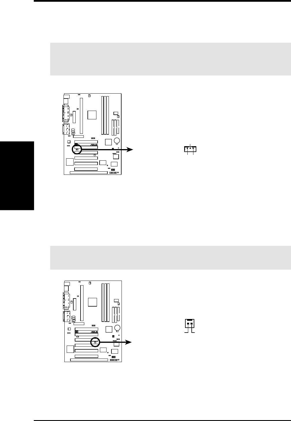
14) Wake-On-Ring Connector (2-pin WOR)
This connector connects to internal modem cards with a Wake-On-Ring output.
The connector powers up the system when a ringup packet or signal is received
through the internal modem card. NOTE: For external modems, Wake-On-Ring
is detected through the COM port.
IMPORTANT: This feature requires that PWR Up On Modem Act is set to
Enabled (see 4.5.1 Power Up Control).
P3W Wake-On-Ring Connector
WOR
RI#Ground
2
1
10 10 1
®
P3W
ASUS P3W User’s Manual 41
3. HARDWARE SETUP
Connectors
3. H/W SETUP
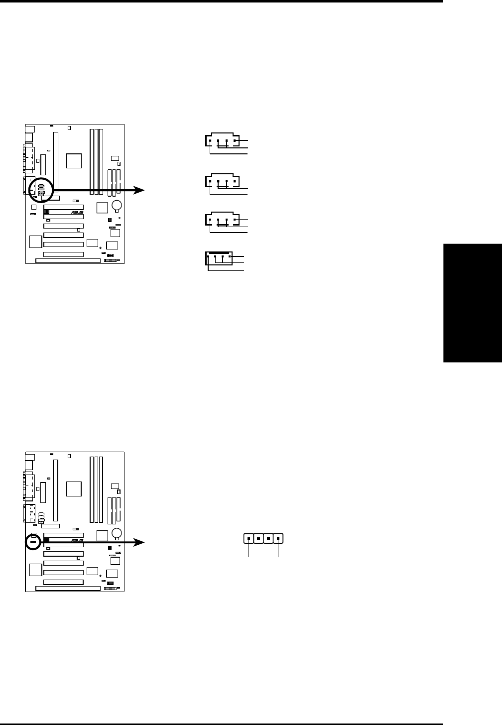
15) Internal Audio Connectors (4-pin VIDEO, AUX, CD1, MODEM)
These connectors allow you to receive stereo audio input from such sound sources
as a CD-ROM, TV tuner, or MPEG card. The MODEM connector allows the
onboard audio to interface with a voice modem card with a similar connector. It
also allows the sharing of mono_in (such as a phone) and mono_out (such as a
speaker) between the onboard audio and the voice modem card.
10 10 1
®
P3W
P3W Internal Audio Connectors
MODEM
Modem-Out (from Modem)
Ground
Modem-In (to Modem)
CD1 (Black)
Right Audio Channel
Left Audio Channel
Ground
AUX (White)
Right Audio Channel
Left Audio Channel
Ground
VIDEO (Green)
Right Audio Channel
Left Audio Channel
Ground
16) Internal Speaker Connector (SPKR)
This connector allows you to connect the internal chassis speaker to the onboard
audio’s output. This will allow you to use the chassis’ built-in speaker to listen to
sounds normally requiring separately purchased external speakers. The ground
(GND) wire is usually the black wire and the speaker-out (SPKOUT) is usually
the red wire. System beeps and warnings sent through the chassis speaker con-
nector are also routed through this internal speaker connector so that there is no
need for two speakers.
10 10 1
®
P3W
P3W Internal Speaker Connector
SPKR
SPKOUT GND
14
42 ASUS P3W User’s Manual
Connectors
3. H/W SETUP
3. HARDWARE SETUP
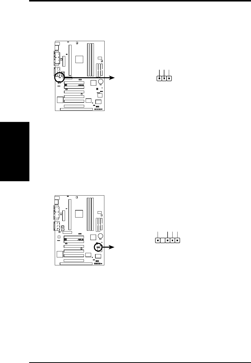
17) Internal Microphone Connector (3 pin INT MIC)
This connector allows you to connect a chassis mounted microphone to the
motherboard instead of having to attach an external microphone to the ATX
connectors.
10 10 1
®
P3W
P3W Internal Microphone Connector
MIC Power
13
MIC Input
Ground
INT
MIC
18) SMBus Connector (5-1 pin SMB)
This connector allows you to connect SMBus (System Management Bus) de-
vices. SMBus devices communicate by means of the SMBus with an SMBus
host and/or other SMBus devices. SMBus is a specific implementation of an I
2
C
bus, which is a multi-device bus; that is, multiple chips can be connected to the
same bus and each one can act as a master by initiating data transfer.
10 10 1
®
P3W
SMBCLK
Ground
SMBDATA
+5V
1
P3W SMBus Connector
SMB
ASUS P3W User’s Manual 43
3. HARDWARE SETUP
Connectors
3. H/W SETUP
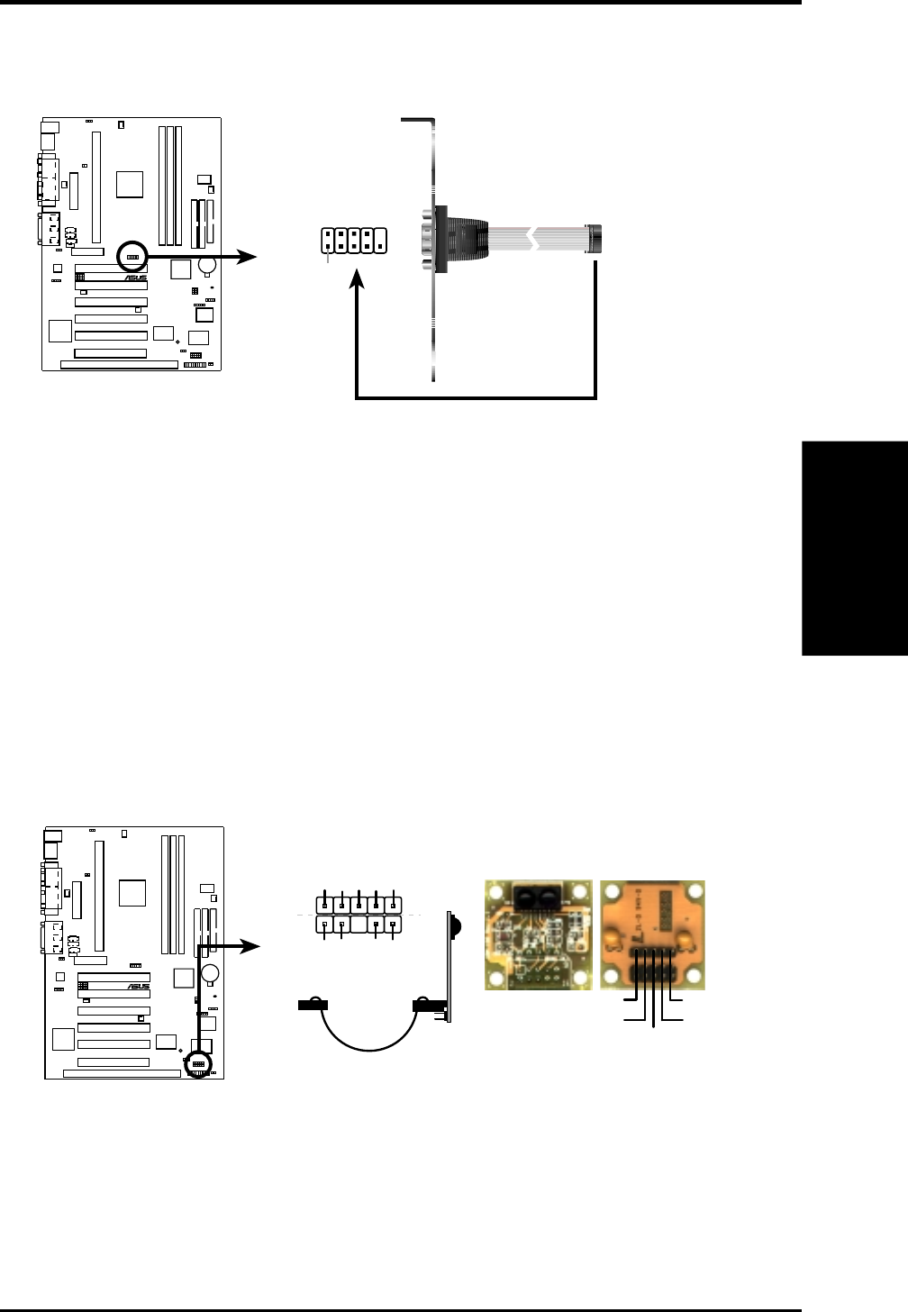
19) Serial Port COM 2 Header (10-1 pin COM2)
The optional serial port bracket can be used to add an additional serial port for
additional serial devices.
10 10 1
®
P3W
P3W Serial COM2 Bracket
Pin 1 to COM2 Header
20) Serial IR (SIR) (5-pin) and Consumer IR (CIR) (5-1 pin) Connectors
This connector supports an optional wireless transmitting and receiving infrared
module. This module mounts to a small opening on system cases that support
this feature. You must also configure the setting through UART2 Use Infrared
(see 4.4.2 I/O Device Configuration) to select whether UART2 is directed for
use with COM2 or IrDA. Use the five pins as shown in Back View and connect
a ribbon cable from the module to the motherboard’s SIR connector according
to the pin definitions. An optional consumer infrared (CIR) set connects to the
CIR and SIR connectors simultaneously for both wireless transmitting and re-
mote control functions through one external infrared module. Wake On PS2
KB/Mouse in 4.5.1 Power Up Control must be Enabled in order to use Con-
sumer Infrared (CIR) power up.
10 10 1
®
P3W
P3W Infrared Module Connector
Standard Infrared (SIR)
Front View Back View
+5V
IRTX
IRRX (NC)
GND
SIR
+5V
IRRX
IRTX
(NC)
GND
(NC)
GND
CIRRX
CIR+5V
CIR

44 ASUS P3W User’s Manual
Connectors
3. H/W SETUP
3. HARDWARE SETUP
21) Chassis Intrusion Alarm Connector (4-1 pin ACHA)
This connector is for a chassis designed for chassis intrusion detection. After-
market toggle switches may also be installed to the chassis panel or on any
removable components. Two wires should be available from the chassis to con-
nect to this. When any chassis component is removed, the contact should open
and the motherboard will record a chassis intrusion event. If the chassis intru-
sion alarm connector is not used, a jumper cap must be placed over pins 2 and 3
to prevent unnecessary power loss.
P3W Chassis Open Alarm Lead
ACHA
+5Volt
(Power Supply Stand By)
Ground
Chassis Signal
1
10 10 1
®
P3W
ASUS P3W User’s Manual 45
3. HARDWARE SETUP
Connectors
3. H/W SETUP
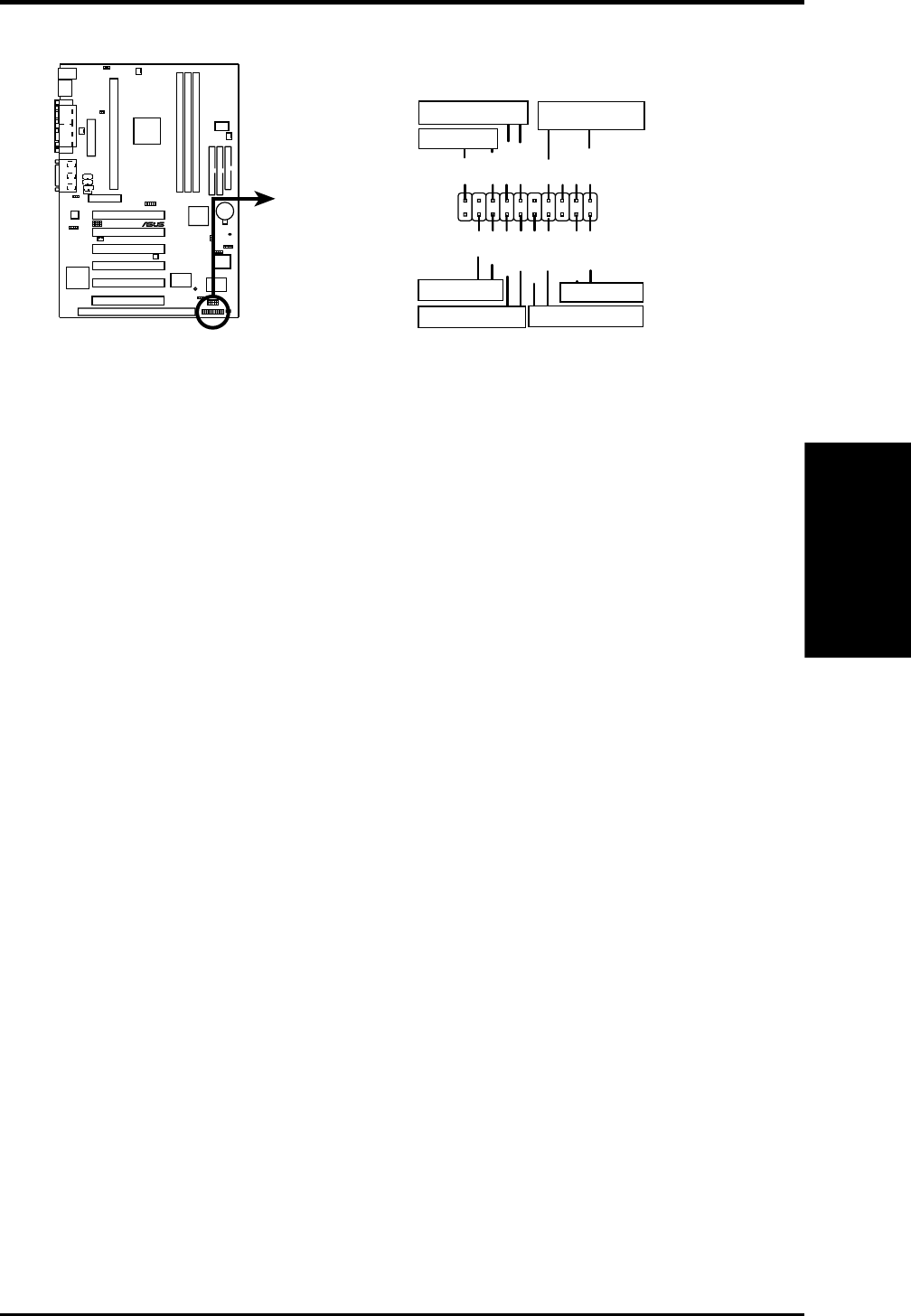
The following PANEL illustration is used for items 22-28
10 10 1
®
P3W
P3W System Panel Connectors
*
Requires an ATX power supply.
Keyboard Lock
PLED
Ground
MLED
PWR_SW
+5 V
Keylock
+5V
SPKR
Ground
+5 V
ExtSMI#
ResetCon
Ground
Ground
Ground
Reset SW
Power LED
ATX Power Switch*
Message LED
SMI Lead
Speaker
Connector
Ground
22) System Power LED Lead (3-1 pin KEYLOCK)
This 3-1 pin connector connects the system power LED, which lights when the
system is powered on and blinks when it is in sleep mode.
23) Keyboard Lock Switch Lead (2-pin KEYLOCK)
This 2-pin connector connects to the case-mounted key switch to allow key-
board locking.
24) System Warning Speaker Connector (4-pin SPEAKER)
This 4-pin connector connects to the case-mounted speaker.
25) Reset Switch Lead (2-pin RESET)
This 2-pin connector connects to the case-mounted reset switch for rebooting
your computer without having to turn off your power switch. This is a preferred
method of rebooting to prolong the life of the system’s power supply.
26) ATX Power Switch Lead (2-pin PWR)
The system power is controlled by a momentary switch connected to this lead.
Pressing the button once will switch the system between ON and SOFT OFF.
Pushing the switch while in the ON mode for more than 4 seconds will turn the
system off. The system power LED shows the status of the system’s power.
27) System Management Interrupt Lead (2-pin SMI)
This allows the user to manually place the system into a suspend mode or “Green”
mode, where system activity is decreased to save electricity and expand the life
of certain components when the system is not in use. This 2-pin connector con-
nects to the case-mounted suspend switch. If you do not have a switch for the
connector, you may use the “Turbo Switch.” SMI is activated when it detects a
short to open moment and therefore leaving it shorted will not cause any prob-
lems. This may require one or two presses depending on the position of the
switch. Wake-up can be controlled by settings in the BIOS but the keyboard will
always allow wake-up (the SMI lead cannot wake up the system).
28) Message LED Lead (2-pin LED)
This indicates whether a message has been received from a fax/modem. The
LED will remain lit when there is no signal and blink when there is data transfer
or waiting in the inbox. This function requires ACPI OS and driver support.
46 ASUS P3W User’s Manual
Connectors
3. H/W SETUP
3. HARDWARE SETUP
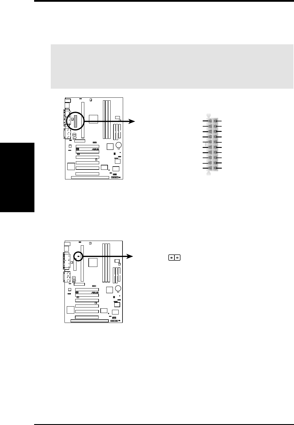
29) ATX Power Supply Connector (20-pin block ATXPWR)
This connector connects to an ATX power supply. The plug from the power sup-
ply will only insert in one orientation because of the different hole sizes. Find the
proper orientation and push down firmly making sure that the pins are aligned.
IMPORTANT: Make sure that your ATX power supply can supply at least 10mA
on the +5-volt standby lead (+5VSB). You may experience difficulty in power-
ing ON your system if your power supply cannot support the load. For Wake-
On-LAN support, your ATX power supply must supply at least 720mA +5VSB.
10 10 1
®
P3W
P3W ATX Power Connector
+3.3Volts
-12.0Volts
Ground
Power Supply On
Ground
Ground
Ground
-5.0 Volts
+5.0 Volts
+5.0 Volts
Power Good
+12.0Volts
+3.3 Volts
+3.3 Volts
Ground
+5.0 Volts
Ground
+5.0 Volts
Ground
+5V Standby
30) Thermal Sensor Connector (2-pin JTPWR)
If you have a power supply with thermal monitoring, connect its thermal sensor
cable to this connector.
10 10 1
®
P3W
P3W Thermal Sensor Connector
Power Supply
Thermal Sensor Connector
JTPWR

ASUS P3W User’s Manual 47
3. HARDWARE SETUP
Power Connections
3. H/W SETUP
3.9 Power Connection Procedures
1. After all connections are made, close the system case cover.
2. Be sure that all switches are off (in some systems, marked with ).
3. Connect the power supply cord into the power supply located on the
back of your system case according to your system user’s manual.
4. Connect the power cord into a power outlet that is equipped with a surge
protector.
5. You may then turn on your devices in the following order:
a. Your monitor
b. External SCSI devices (starting with the last device on the chain)
c. Your system power. For ATX power supplies, you need to switch on
the power supply as well as press the ATX power switch on the front
of the case.
6. The power LED on the front panel of the system case will light. For
ATX power supplies, the system LED will light when the ATX power
switch is pressed. The LED on the monitor may light up or switch be-
tween orange and green after the system’s if it complies with “green”
standards or if it has a power standby feature. The system will then run
power-on tests. While the tests are running, additional messages will
appear on the screen. If you do not see anything within 30 seconds from
the time you turn on the power, the system may have failed a power-on
test. Recheck your jumper settings and connections or call your retailer
for assistance.
7. During power-on, hold down <Delete> to enter BIOS setup. Follow the
instructions in 4. BIOS SETUP.
* Powering Off your computer: You must first exit or shut down your
operating system before switching off the power switch. For ATX power
supplies, you can press the ATX power switch after exiting or shutting
down your operating system. If you are using Windows 95/98, click the
Start button, click Shut Down, and then click Shut down the com-
puter? The power supply should turn off after Windows shuts down.
NOTE: The message “You can now safely turn off your computer” will
not appear when shutting down with ATX power supplies.
4. BIOS SETUP
Updating BIOS
4. BIOS SETUP
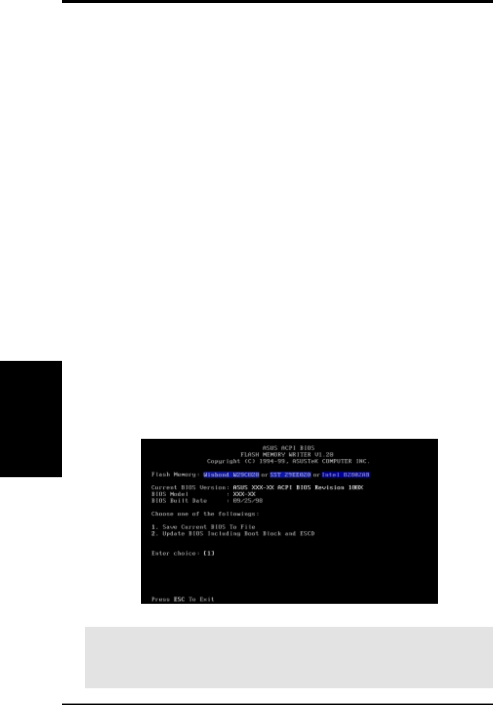
4.1 Managing and Updating Your BIOS
4.1.1 Upon First Use of the Computer System
It is recommended that you save a copy of the original motherboard BIOS
along with a Flash Memory Writer utility (AFLASH.EXE) to a bootable
floppy disk in case you need to reinstall the BIOS later. AFLASH.EXE is a
Flash Memory Writer utility that updates the BIOS by uploading a new
BIOS file to the programmable flash ROM on the motherboard. This file
works only in DOS mode. To determine the BIOS version of your mother-
board, check the last four numbers of the code displayed on the upper left-
hand corner of your screen during bootup. Larger numbers represent a newer
BIOS file.
1. Type FORMAT A:/S at the DOS prompt to create a bootable system
floppy disk. DO NOT copy AUTOEXEC.BAT & CONFIG.SYS to the
disk.
2. Type COPY D:\AFLASH\AFLASH.EXE A:\ (assuming D is your CD-
ROM drive) to copy AFLASH.EXE to the just created boot disk.
NOTE: AFLASH works only in DOS mode. It will not work with DOS
prompt in Windows and will not work with certain memory drivers that
may be loaded when you boot from your hard drive. It is recommended
that you reboot using a floppy.
3. Reboot your computer from the floppy disk. NOTE: BIOS setup must
specify “Floppy” as the first item in the boot sequence.
4. In DOS mode, type A:\AFLASH <Enter> to run AFLASH.
IMPORTANT! If “unknown” is displayed after Flash Memory:, the memory
chip is either not programmable or is not supported by the ACPI BIOS and there-
fore, cannot be programmed by the Flash Memory Writer utility.
ASUS P3W User’s Manual48
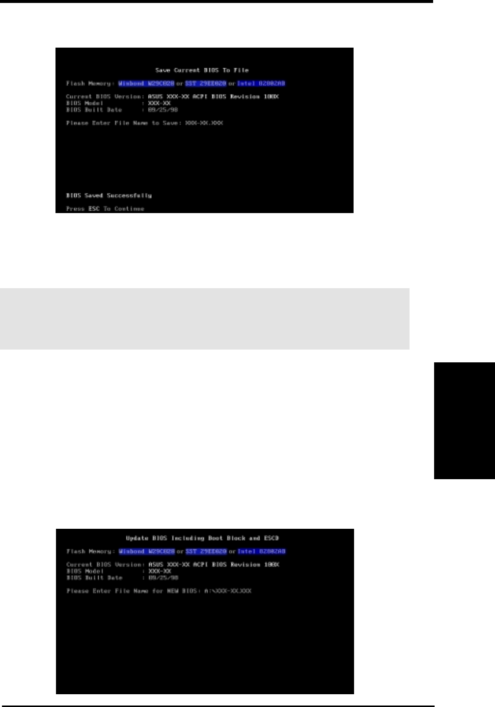
ASUS P3W User’s Manual 49
4. BIOS SETUP
4. BIOS SETUP
Updating BIOS
5. Select 1. Save Current BIOS to File from the Main menu and press
<Enter>. The Save Current BIOS To File screen appears.
6. Type a filename and the path, for example, A:\XXX-XX.XXX and then
press <Enter>.
4.1.2 Updating BIOS Procedures
WARNING! Only update your BIOS if you have problems with your mother-
board and you know that the new BIOS revision will solve your problems. Care-
less updating can result in your motherboard having more problems!
1. Download an updated ASUS BIOS file from the Internet (WWW or
FTP) (see ASUS CONTACT INFORMATION on page 3 for details)
and save to the disk you created earlier.
2. Boot from the disk you created earlier.
3. At the “A:\” prompt, type AFLASH and then press <Enter>.
4. At the Main Menu, type 2 and then press <Enter>. The Update BIOS
Including Boot Block and ESCD screen appears.
5. Type the filename of your new BIOS and the path, for example, A:\XXX-
XX.XXX, and then press <Enter>.
NOTE: To cancel this operation, press <Enter>.
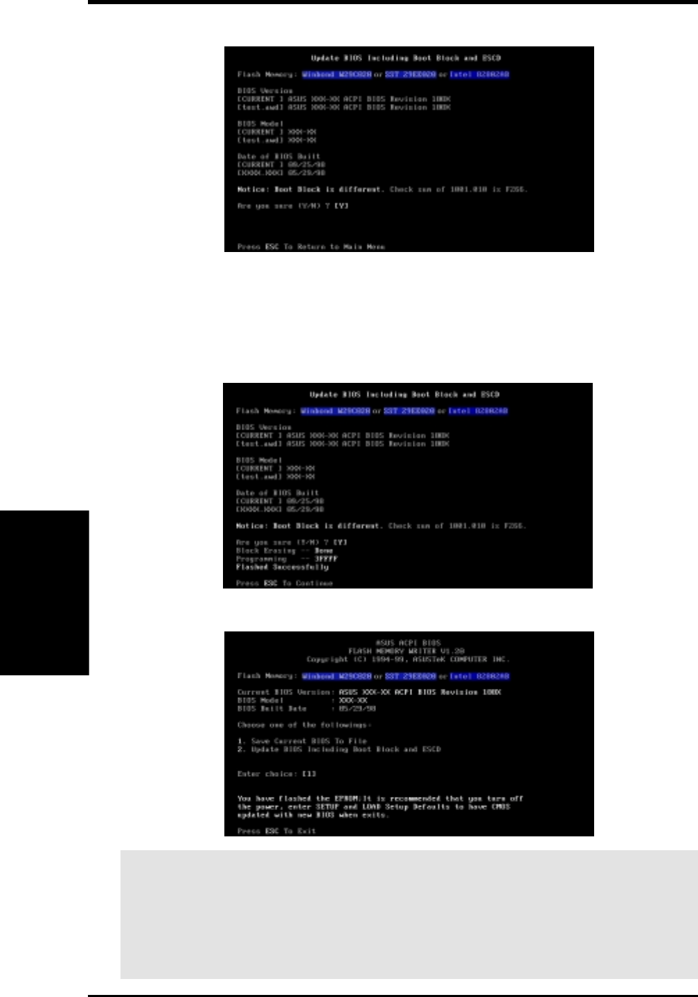
ASUS P3W User’s Manual50
4. BIOS SETUP
4. BIOS SETUP
Updating BIOS
6. When prompted to confirm the BIOS update, press Y to start the update.
7. The utility starts to program the new BIOS information into the flash
ROM. The boot block will be updated automatically only when neces-
sary. This will minimize the chance that a failed update will prevent
your system from booting up. When the programming is finished, Flashed
Successfully will be displayed.
8. Follow the onscreen instructions to continue.
WARNING! If you encounter problems while updating the new BIOS, DO NOT
turn off your system since this might prevent your system from booting up. Just
repeat the process, and if the problem still persists, update the original BIOS file
you saved to disk above. If the Flash Memory Writer utility was not able to
successfully update the BIOS file, your system may not be able to boot up. If this
happens, your system will need servicing.

ASUS P3W User’s Manual 51
4. BIOS SETUP
4. BIOS SETUP
4.2 BIOS Setup Program
This motherboard supports a programmable EEPROM that can be updated using
the provided utility as described in 4.1 Managing and Updating Your BIOS.
The utility is used if you are installing a motherboard, reconfiguring your system,
or prompted to “Run Setup”. This section describes how to configure your system
using this utility.
Even if you are not prompted to use the Setup program, at some time in the future
you may want to change the configuration of your computer. For example, you
may want to enable the Security Password Feature or make changes to the power
management settings. It will then be necessary to reconfigure your system using
the BIOS Setup program so that the computer can recognize these changes and
record them in the CMOS RAM of the EEPROM.
The EEPROM on the motherboard stores the Setup utility. When you start up the
computer, the system provides you with the opportunity to run this program. This
appears during the Power-On Self Test (POST). Press <Delete> to call up the Setup
utility. If you are a little bit late in pressing the mentioned key, POST will continue
with its test routines, thus preventing you from calling up Setup. If you still need to
call Setup, restart the system by pressing <Ctrl> + <Alt> + <Delete>, or by press-
ing the Reset button on the system chassis. You can also restart by turning the
system off and then back on again. But do so only if the first two methods fail.
The Setup program has been designed to make it as easy to use as possible. It is a
menu-driven program, which means you can scroll through the various sub-menus
and make your selections among the predetermined choices.
To access the BIOS Setup program, press the <Delete> key after
the computer has run through its POST.
NOTE: Because the BIOS software is constantly being updated, the following
BIOS screens and descriptions are for reference purposes only and may not re-
flect your BIOS screens exactly.
Program Information

ASUS P3W User’s Manual52
4. BIOS SETUP
4. BIOS SETUP
4.2.1 BIOS Menu Bar
The top of the screen has a menu bar with the following selections:
MAIN Use this menu to make changes to the basic system configuration.
ADVANCED Use this menu to enable and make changes to the advanced
features.
POWER Use this menu to configure and enable Power Management
features.
BOOT Use this menu to configure the default system device used to lo-
cate and load the Operating System.
EXIT Use this menu to exit the current menu or specify how to exit the
Setup program.
To access the menu bar items, press the right or left arrow key on the keyboard
until the desired item is highlighted.
4.2.2 Legend Bar
At the bottom of the Setup screen you will notice a legend bar. The keys in the
legend bar allow you to navigate through the various setup menus. The following
table lists the keys found in the legend bar with their corresponding alternates and
functions.
Navigation Key(s) Function Description
<F1> or <Alt + H> Displays the General Help screen from anywhere in the BIOS
Setup
<Esc> Jumps to the Exit menu or returns to the main menu from a sub-
menu
← or → (keypad arrow) Selects the menu item to the left or right
↑ or ↓ (keypad arrow) Moves the highlight up or down between fields
- (minus key) Scrolls backward through the values for the highlighted field
+ (plus key) or spacebar Scrolls forward through the values for the highlighted field
<Enter> Brings up a selection menu for the highlighted field
<Home> or <PgUp> Moves the cursor to the first field
<End> or <PgDn> Moves the cursor to the last field
<F5> Resets the current screen to its Setup Defaults
<F10> Saves changes and exits Setup
Menu Introduction
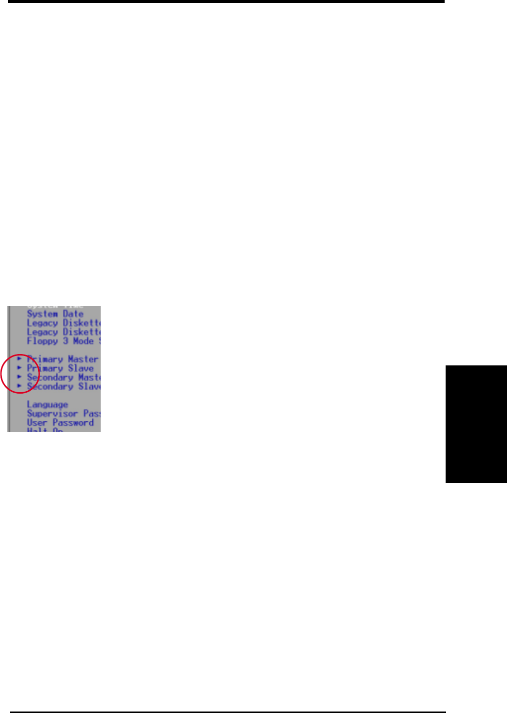
ASUS P3W User’s Manual 53
4. BIOS SETUP
4. BIOS SETUP
General Help
In addition to the Item Specific Help window, the BIOS setup program also pro-
vides a General Help screen. This screen can be called up from any menu by sim-
ply pressing <F1> or the <Alt> + <H> combination. The General Help screen lists
the legend keys with their corresponding alternates and functions.
Saving Changes and Exiting the Setup Program
See 4.7 Exit Menu for detailed information on saving changes and exiting the
setup program.
Scroll Bar
When a scroll bar appears to the right of a help window, it indicates that there is
more information to be displayed that will not fit in the window. Use <PgUp> and
<PgDn> or the up and down arrow keys to scroll through the entire help docu-
ment. Press <Home> to display the first page, press <End> to go to the last page.
To exit the help window, press <Enter> or <Esc>.
Sub-Menu Note that a right pointer symbol (as shown in the left view)
appears to the left of certain fields. This pointer indicates that
a sub-menu can be launched from this field. A sub-menu con-
tains additional options for a field parameter. To call up a sub-
menu, simply move the highlight to the field and press <En-
ter>. The sub-menu will then immediately appear. Use the
legend keys to enter values and move from field to field within
a sub-menu just as you would within a menu. Use the <Esc>
key to return to the main menu.
Take some time to familiarize yourself with each of the legend keys and their
corresponding functions. Practice navigating through the various menus and sub-
menus. If you accidentally make unwanted changes to any of the fields, use the set
default hot key <F5>. While moving around through the Setup program, note that
explanations appear in the Item Specific Help window located to the right of each
menu. This window displays the help text for the currently highlighted field.
NOTE: The item heading in square brackets represents the default setting for
that field.
Menu Introduction
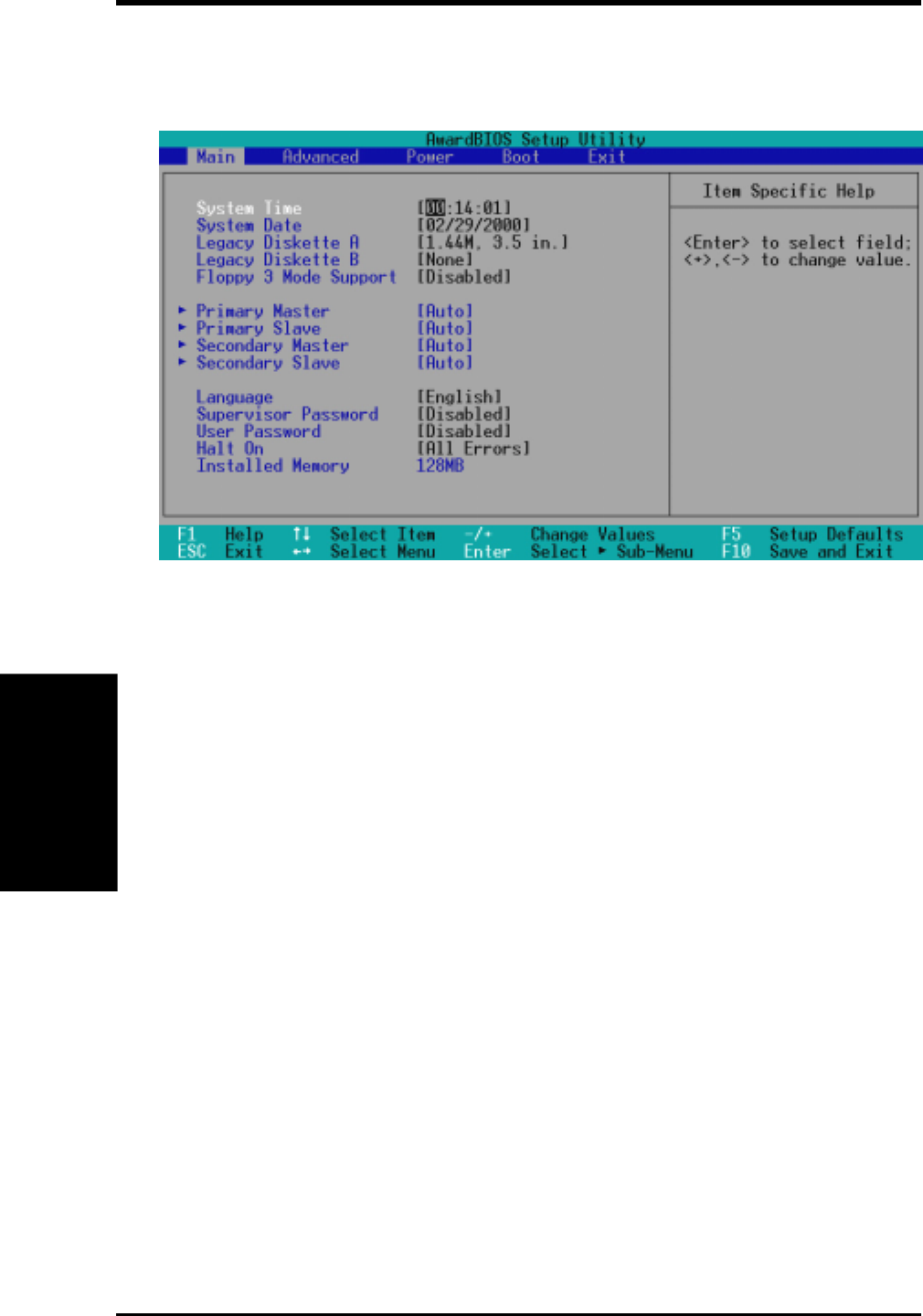
ASUS P3W User’s Manual54
4. BIOS SETUP
4. BIOS SETUP
System Time [XX:XX:XX]
Sets your system to the time that you specify (usually the current time).
The format is hour, minute, second. Valid values for hour, minute and sec-
ond are Hour: (00 to 23), Minute: (00 to 59), Second: (00 to 59). Use the
<Tab> or <Shift> + <Tab> keys to move between the hour, minute, and
second fields.
System Date [XX/XX/XXXX]
Sets your system to the date that you specify (usually the current date). The
format is month, day, year. Valid values for month, day, and year are Month:
(1 to 12), Day: (1 to 31), Year: (100 year range). Use the <Tab> or <Shift>
+ <Tab> keys to move between the month, day, and year fields.
Legacy Diskette A [1.44M, 3.5 in.], Legacy Diskette B [None]
Sets the type of floppy drives installed. Configuration options: [None]
[360K, 5.25 in.] [1.2M , 5.25 in.] [720K , 3.5 in.] [1.44M, 3.5 in.]
[2.88M, 3.5 in.]
Floppy 3 Mode Support [Disabled]
This is required to support older Japanese floppy drives. Floppy 3 Mode
support will allow reading and writing of 1.2MB (as opposed to 1.44MB)
on a 3.5-inch diskette. Configuration options: [Disabled] [Drive A]
[Drive B] [Both]
4.3 Main Menu
When the Setup program is accessed, the following screen appears:
Main Menu
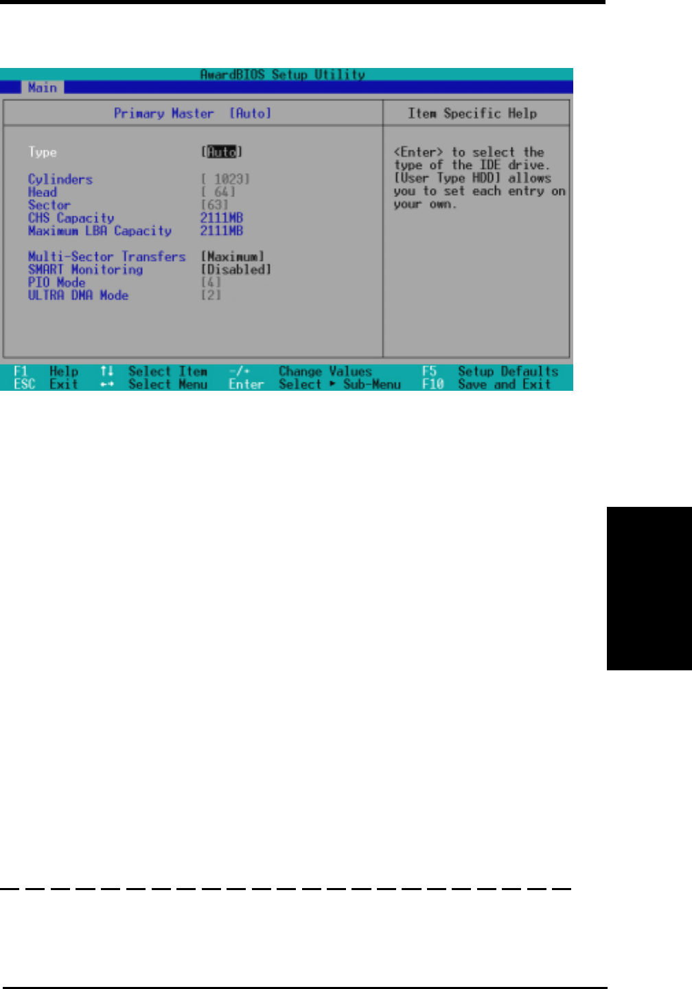
ASUS P3W User’s Manual 55
4. BIOS SETUP
4. BIOS SETUP
NOTE: Before attempting to configure a hard disk drive, make sure you
have the configuration information supplied by the manufacturer of the
drive. Incorrect settings may cause your system to not recognize the in-
stalled hard disk. To allow the BIOS to detect the drive type automati-
cally, select [Auto].
Type [Auto]
Select [Auto] to automatically detect an IDE hard disk drive. If automatic
detection is successful, the correct values will be filled in for the remaining
fields on this sub-menu. If automatic detection fails, your hard disk drive
may be too old or too new. You can try updating your BIOS or enter the
IDE hard disk drive parameters manually.
NOTE: After the IDE hard disk drive information has been entered into
BIOS, new IDE hard disk drives must be partitioned (such as with FDISK)
and then formatted before data can be read from and write on. Primary
IDE hard disk drives must have its partition set to active (also possible
with FDISK).
Other options for the Type field are:
[None] - to disable IDE devices
4.3.1 Primary & Secondary Master/Slave
Master/Slave Drives
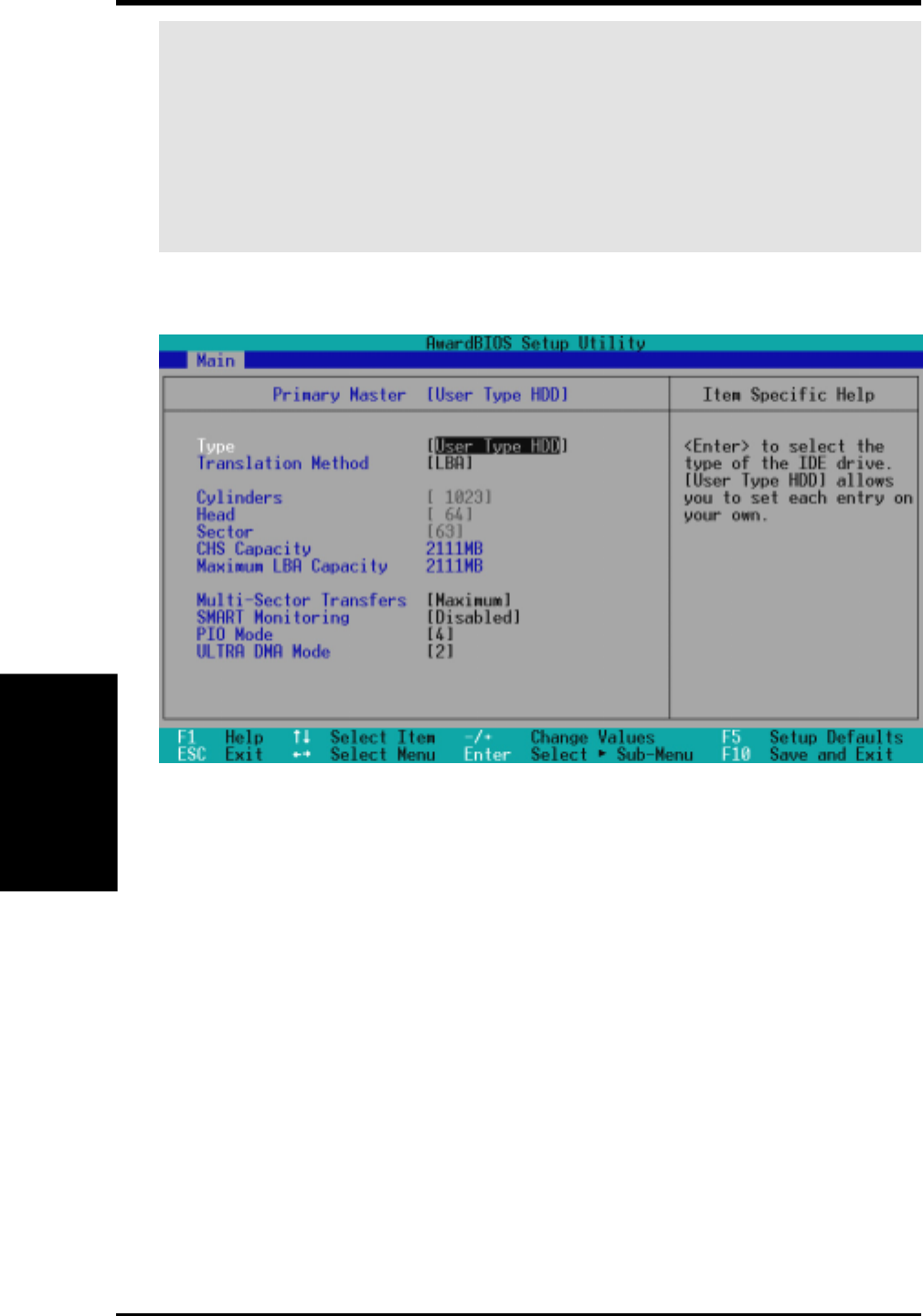
ASUS P3W User’s Manual56
4. BIOS SETUP
4. BIOS SETUP
IMPORTANT: If your hard disk was already formatted on an older previous system,
incorrect parameters may be detected. You will need to enter the correct parameters
manually or use low-level format if you do not need the data stored on the hard disk.
If the parameters listed differ from the ones used when the disk was formatted, the
disk will not be readable. If the auto-detected parameters do not match the ones that
should be used for your disk, you should enter the correct ones manually by setting
[User Type HDD].
Master/Slave Drives
[User Type HDD]
Manually enter the number of cylinders, heads and sectors per track for your drive.
Refer to your drive documentation or look on the drive for this information. If no
drive is installed or if you are removing a drive and not replacing it, select [None].
Translation Method [LBA]
Select the hard disk drive type in this field. When Logical Block Addressing is
enabled, 28-bit addressing of the hard drive is used without regard for cylinders,
heads, or sectors. Note that LBA Mode is necessary for drives with greater than
504MB in storage capacity. Configuration options: [LBA] [LARGE] [Normal]
[Match Partition Table] [Manual]
Cylinders
This field configures the number of cylinders. Refer to your drive documentation
to determine the correct value to enter into this field. NOTE: To make changes to
this field, the Type field must be set to [User Type HDD] and the Translation
Method field must be set to [Manual].

ASUS P3W User’s Manual 57
4. BIOS SETUP
4. BIOS SETUP
Master/Slave Drives
Head
This field configures the number of read/write heads. Refer to your drive documenta-
tion to determine the correct value to enter into this field. NOTE: To make changes to
this field, the Type field must be set to [User Type HDD] and the Translation Method
field must be set to [Manual].
Sector
This field configures the number of sectors per track. Refer to your drive docu-
mentation to determine the correct value to enter into this field. NOTE: To make
changes to this field, the Type field must be set to [User Type HDD] and the Trans-
lation Method field must be set to [Manual].
CHS Capacity
This field shows the drive’s maximum CHS capacity calculated automatically by
the BIOS from the drive information you entered.
Maximum LBA Capacity
This field shows the drive’s maximum LBA capacity calculated automatically by
the BIOS from the drive information you entered.
Multi-Sector Transfers [Maximum]
This option automatically sets the number of sectors per block to the highest number
supported by the drive. This field can also be configured manually. Note that when
this field is automatically configured, the set value may not always be the fastest
value for the drive. Refer to the documentation that came with your hard drive to
determine the optimal value and set it manually. NOTE: To make changes to this
field, the Type field must be set to [User Type HDD]. Configuration options: [Dis-
abled] [2 Sectors] [4 Sectors] [8 Sectors] [16 Sectors] [32 Sectors] [Maximum]
SMART Monitoring [Disabled]
This allows the enabling or disabling of the S.M.A.R.T. (Self-Monitoring, Analy-
sis and Reporting Technology) system which utilizes internal hard disk drive moni-
toring technology. This feature is normally disabled because system resources used
in this feature may decrease system performance. Configuration options: [Dis-
abled] [Enabled]
PIO Mode [4]
This option lets you set a PIO (Programmed Input/Output) mode for the IDE de-
vice. Modes 0 through 4 provide successively increased performance. Configura-
tion options: [0] [1] [2] [3] [4]
Ultra DMA Mode [Disabled]
Ultra DMA capability allows improved transfer speeds and data integrity for com-
patible IDE devices. Set to [Disabled] to suppress Ultra DMA capability. NOTE:
To make changes to this field, the Type field must be set to [User Type HDD].
Configuration options: [0] [1] [2] [3] [4] [Disabled]

ASUS P3W User’s Manual58
4. BIOS SETUP
4. BIOS SETUP
Other options for “Type:” are:
[CD-ROM] - for IDE CD-ROM drives
[LS-120] - for LS-120 compatible floppy disk drives
[ZIP-100] - for ZIP-100 compatible disk drives
[MO] - for IDE magneto optical disk drives
[Other ATAPI Device] - for IDE devices not listed here
After using the legend keys to make your selections on this sub-menu, press
the <Esc> key to exit back to the Main menu. When the Main menu ap-
pears, you will notice that the drive size appear in the field for the hard disk
drive that you just configured.
Language [English]
This allows selection of the BIOS’ displayed language. Currently only English
is available.
Supervisor Password [Disabled], User Password [Disabled]
These fields allow you to set the passwords. To set the password, highlight the ap-
propriate field and press <Enter>.
Type in a password and press <Enter>. You can type up to eight alphanumeric char-
acters. Symbols and other keys are ignored. To confirm the password, type the pass-
word again and press the <Enter>. The password is now set to [Enabled]. This pass-
word allows full access to the BIOS Setup menus.
To clear the password, highlight this field and press <Enter>. The same dialog box
as above will appear. Press <Enter> and the password will be set to [Disabled].
A Note about Passwords
The BIOS Setup program allows you to specify passwords in the Main menu. The
passwords control access to the BIOS during system startup. The passwords are not
case sensitive. In other words, it makes no difference whether you enter a password
using upper or lowercase letters.
The BIOS Setup program allows you to specify two separate passwords: a Supervisor
password and a User password. When disabled, anyone may access all BIOS Setup
program functions. When enabled, the Supervisor password is required for entering
the BIOS Setup program and having full access to all configuration fields.
Main Menu
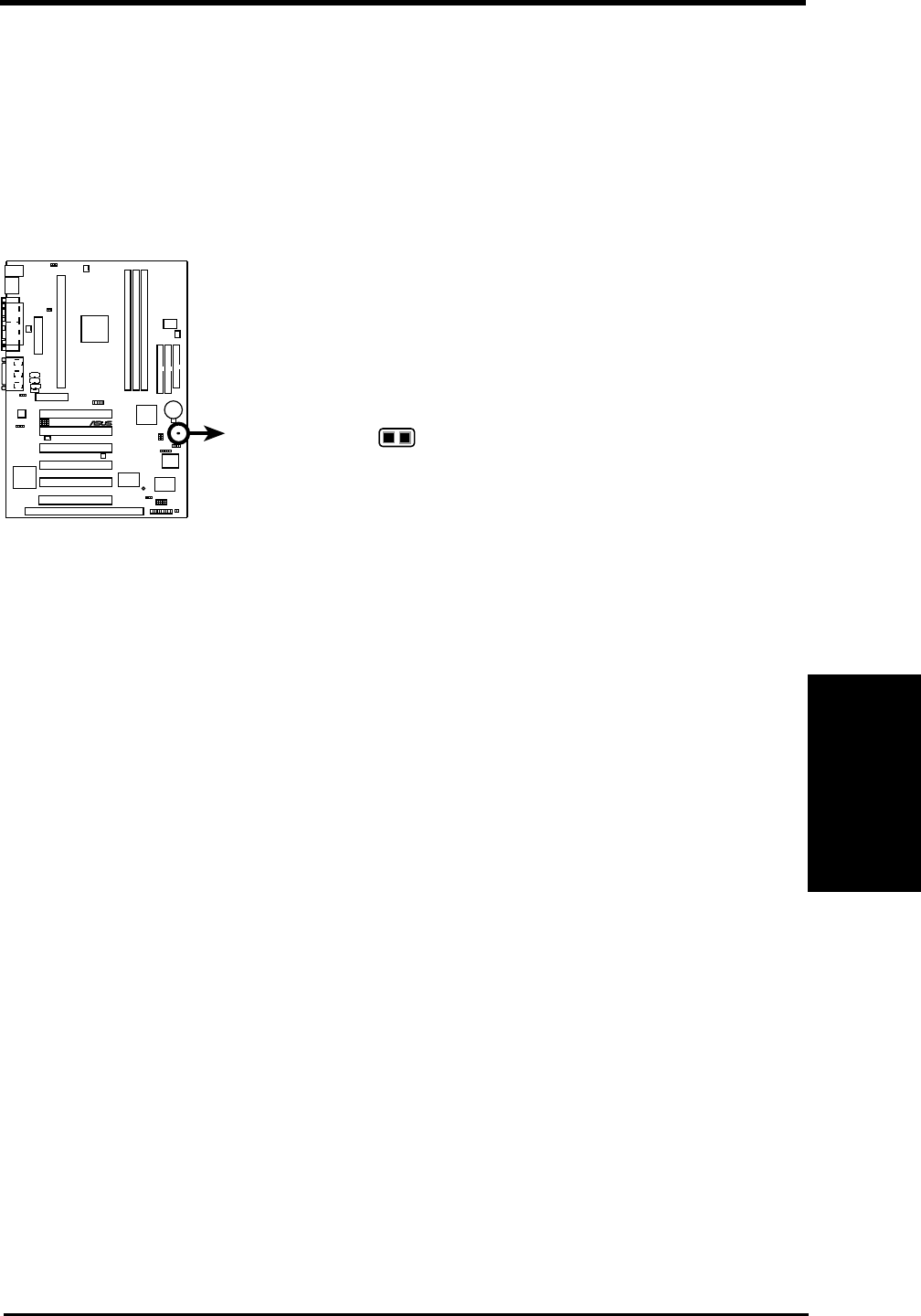
ASUS P3W User’s Manual 59
4. BIOS SETUP
4. BIOS SETUP
Main Menu
Forgot the password?
If you forgot the password, you can clear the password by erasing the CMOS
Real Time Clock (RTC) RAM. The RAM data containing the password
information is powered by the onboard button cell battery. To erase the
RTC RAM: (1) Unplug your computer, (2) Short the solder points, (3) Turn
ON your computer, (4) Hold down <Delete> during bootup and enter BIOS
setup to re-enter user preferences.
Halt On [All Errors]
This field determines which types of errors will cause the system to halt.
Configuration options: [All Errors] [No Error] [All but Keyboard] [All but
Disk] [All but Disk/Keyboard]
Installed Memory [XXX MB]
This field displays the amount of conventional memory detected by the
system during bootup. You do not need to make changes to this field. This
is a display only field.
P3W Clear RTC RAM
Short solder points
to Clear CMOS
CLRTC
10 10 1
®
P3W
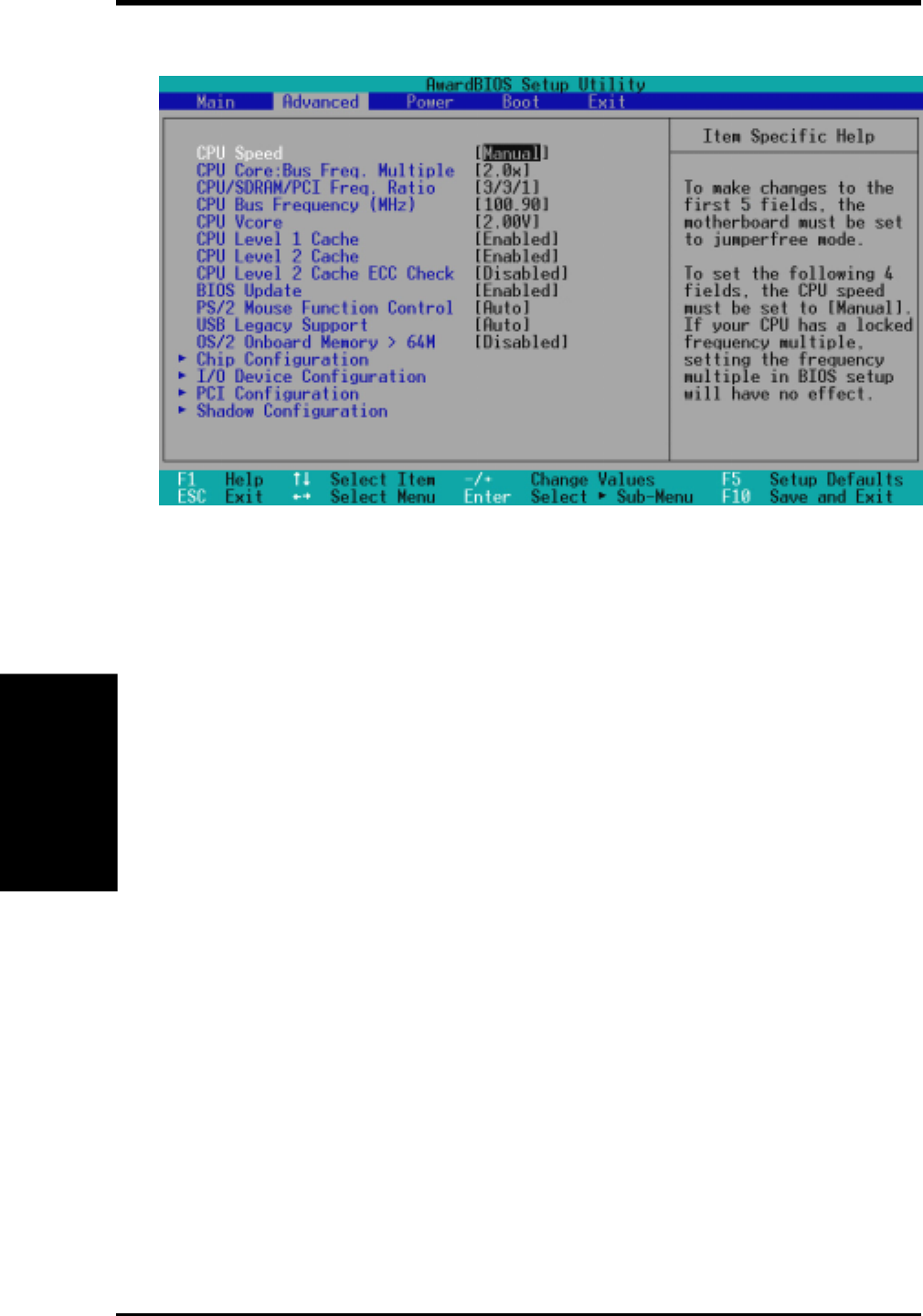
ASUS P3W User’s Manual60
4. BIOS SETUP
4. BIOS SETUP
4.4 Advanced Menu
CPU Speed [Manual]
When the motherboard is set to JumperFree™ mode, this field allows you
to select the internal speed of your CPU. Once a specific CPU speed is
selected, the correct values will be filled in for the subsequent 3 fields. Se-
lect [Manual] if you want to make changes to the subsequent 3 fields. Con-
figuration options: [Manual] [300MHz] [350MHz]...[733MHz]
CPU Core:Bus Freq. Multiple (when CPU Speed is set to [Manual])
This field is for unlocked processors only. If your socket 370 processor’s
Frequency Multiple is locked, setting the Frequency Multiple here will have
no effect. This field sets the frequency multiple between the CPU’s internal
frequency and external frequency. This must be set in conjunction with CPU
Bus Frequency to match the speed of your CPU. Configuration options:
[2.0x] [2.5x] [3.0x]...[7.0x] [7.5x] [8.0x]
CPU/SDRAM/PCI Freq. Ratio (when CPU Speed is set to [Manual])
This field determines whether the memory clock frequency is set to be in
synchronous or asynchronous mode with respect to the CPU Bus Frequency.
Each of the two memory data transfer methods leads to a set of 16 CPU Bus
Frequency selections. Configuration options: [2/3/1] [3/3/1]
CPU Bus Frequency (MHz) (when CPU Speed is set to [Manual])
This feature tells the clock generator what frequency to send to the CPU, DRAM,
and chipset. The bus frequency (external frequency) multiplied by the bus mul-
tiple equals the CPU’s internal frequency (the CPU speed). The configuration
options vary depending on the CPU/SDRAM/PCI Freqency Ratio.
Advanced Menu

ASUS P3W User’s Manual 61
4. BIOS SETUP
4. BIOS SETUP
Chip Configuration
CPU Vcore (when CPU Speed is set to [Manual])
This field displays the core voltage supplied to the CPU. If you want to
set it manually, always refer to the CPU documentation for the reason-
able voltage range. Configuration options: [2.40V] [2.30V] [2.20V]
[2.10V] [2.05V] [2.00V]
CPU Level 1 Cache, CPU Level 2 Cache [Enabled]
These fields allow you to choose from the default of [Enabled] or choose
[Disabled] to turn on or off the CPU’s Level 1 and Level 2 built-in cache.
Configuration options: [Disabled] [Enabled]
CPU Level 2 Cache ECC Check [Disabled]
This function controls the ECC capability in the CPU level 2 cache. Con-
figuration options: [Disabled] [Enabled]
BIOS Update [Enabled]
This functions as an update loader integrated into the BIOS to supply the
processor with the required data. In the default position of [Enabled], the
BIOS will load the update on all processors during system bootup. Configu-
ration options: [Disabled] [Enabled]
PS/2 Mouse Function Control [Auto]
The default of [Auto] allows the system to detect a PS/2 mouse on startup.
If detected, IRQ12 will be used for the PS/2 mouse. IRQ12 will be reserved
for expansion cards only if a PS/2 mouse is not detected. [Enabled] will
always reserve IRQ12, whether on startup a PS/2 mouse is detected or not.
Configuration options: [Enabled] [Auto]
USB Legacy Support [Auto]
This motherboard supports Universal Serial Bus (USB) devices. The de-
fault of [Auto] allows the system to detect a USB device on startup. If de-
tected, the USB controller will be enabled. If not detected, the USB control-
ler will be disabled. When this field is set to [Disabled], the USB controller
is disabled no matter whether you are using a USB device or not. Configu-
ration options: [Disabled] [Enabled] [Auto]
OS/2 Onboard Memory > 64M [Disabled]
When using OS/2 operating systems with installed DRAM of greater than
64MB, you need to set this option to [Enabled]; otherwise, leave this on
[Disabled]. Configuration options: [Disabled] [Enabled]
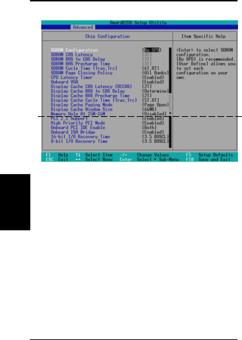
ASUS P3W User’s Manual62
4. BIOS SETUP
4. BIOS SETUP
Chip Configuration
SDRAM Configuration [By SPD]
This sets the optimal timings for items 2–4, depending on the memory mod-
ules that you are using. Default setting is [By SPD], which configures items
2–4 by reading the contents in the SPD (Serial Presence Detect) device. The
EEPROM on the memory module stores critical parameter information about
the module, such as memory type, size, speed, voltage interface, and mod-
ule banks. Configuration options: [User Define] [7ns (143MHz)] [8ns
(125MHz)] [By SPD]
SDRAM CAS Latency
This controls the latency between the SDRAM read command and the time
that the data actually becomes available. NOTE: To make changes to this
field, the SDRAM Configuration field must be set to [User Define].
SDRAM RAS to CAS Delay
This controls the latency between the SDRAM active command and the
read/write command. NOTE: To make changes to this field, the SDRAM
Configuration field must be set to [User Define].
(scroll down to see more items, as shown here)
4.4.1 Chip Configuration

ASUS P3W User’s Manual 63
4. BIOS SETUP
4. BIOS SETUP
SDRAM RAS Precharge Time
This controls the idle clocks after issuing a precharge command to the
SDRAM. NOTE: To make changes to this field, the SDRAM Configura-
tion field must be set to [User Define].
SDRAM Cycle Time (Tras, Trc) [5T, 7T]
This feature controls the number of SDRAM clocks used per access cycle.
Configuration options: [5T, 7T] [6T, 8T]
SDRAM Address Setup Time [1T Delay]
Configuration options: [No Delay] [1T Delay]
SDRAM Page Closing Policy [All Banks]
This feature controls whether the graphic and memory controller hub will
precharge one or all banks after a page miss. Configuration options: [One
Bank] [All Banks]
CPU Latency Timer [Enabled]
Configuration options: [Disabled] [Enabled]
Onboard VGA [Enabled]
Leave on default setting if you want to use the onboard VGA. If this field is
disabled, all Display Cache configurations will not be available. Configura-
tion options: [Disabled] [Enabled]
Display Cache CAS Latency (DCCAS) [2T]
Configuration options: [2T] [3T]
Display Cache RAS to CAS Delay [Determined by DCCAS]
With the default setting [Determined by DCCAS], this field has the same
configuration as Display Cache CAS Latency (DCCAS). Configuration
options: [Determined by DCCAS] [2T]
Display Cache RAS Precharge Time [2T]
Configuration options: [2T] [3T]
Display Cache Cycle Time (Tras, Trc) [5T, 8T]
Configuration options: [5T, 8T] [7T, 10T]
Display Cache Paging Mode [Page Open Mode]
Configuration options: [Page Open Mode] [Page Close Mode]
Display Cache Window Size [64MB]
This feature allows you to select the size of mapped memory for AGP graphic
data. Configuration options: [64MB] [32MB]
Chip Configuration

ASUS P3W User’s Manual64
4. BIOS SETUP
4. BIOS SETUP
Memory Hole At 15M-16M [Disabled]
This field allows you to reserve an address space for ISA expansion cards
that require it. Setting the address space to a particular setting will make
that memory space unavailable to the system. Expansion cards can only
access memory up to 16MB. Configuration options: [Disabled] [Enabled]
PCI 2.1 Support [Enabled]
This function allows you to enable or disable PCI 2.1 features including
passive release and delayed transaction. Configuration options: [Disabled]
[Enabled]
High Priority PCI Mode [Enabled]
This field allows you to give PCI slot 1 a higher priority. You may want to
leave on the default setting if you are using an IEEE-1394 PCI card. Con-
figuration options: [Disabled] [Enabled]
Onboard PCI IDE Enable [Both]
You can select to enable the primary IDE channel, secondary IDE channel,
both, or disable both channels. Configuration options: [Both] [Primary] [Sec-
ondary] [Disabled]
Onboard ISA Bridge [Enabled]
If you are not using any ISA cards, you may disable this field. When this
field is disabled, the 8-bit and 16-bit I/O Recovery Time configurations
will not be available. Configuration options: [Disabled] [Enabled]
8-bit, 16-bit I/O Recovery Time [3.5 BUSCLK]
Leave on default setting.
Chip Configuration

ASUS P3W User’s Manual 65
4. BIOS SETUP
4. BIOS SETUP
Onboard AC97 Modem Controller, Audio Controller [Auto]
[Auto] allows the motherboard’s BIOS to detect whether you are using any modem/
audio device. If a modem/audio device is detected, the onboard modem/audio control-
ler will be enabled; if no modem/audio device is detected, the onboard modem/audio
controller will be disabled. If you have conflicts with the onboard modem/audio con-
troller, you may set the appropriate field to [Disabled]. Configuration options: [Auto]
[Disabled]
Onboard FDC Swap A & B [No Swap]
This field allows you to reverse the hardware drive letter assignments of your floppy
disk drives. Configuration options: [No Swap] [Swap AB]
Floppy Disk Access Control [R/W]
When set to [Read Only], this field protects files from being copied to floppy disks by
allowing reads from the floppy disk drive but not writes. The setup default [R/W]
allows both reads and writes. Configuration options: [R/W] [Read Only]
Onboard Serial Port 1 [3F8H/IRQ4], Onboard Serial Port 2 [2F8H/IRQ3]
These fields allow you to set the addresses for the onboard serial connectors. Serial
Port 1 and Serial Port 2 must have different addresses. Configuration options: [3F8H/
IRQ4] [2F8H/IRQ3] [3E8H/IRQ4] [2E8H/IRQ10] [Disabled]
4.4.2 I/O Device Configuration
I/O Device Config
(scroll down to see more items, as shown here)

ASUS P3W User’s Manual66
4. BIOS SETUP
4. BIOS SETUP
UART2 Use Standard Infrared [Disabled]
When enabled, this field activates the onboard standard infrared feature and sets the
second serial UART to support the infrared module connector on the motherboard. If
your system already has a second serial port connected to the onboard COM2 connec-
tor, it will no longer work if you enable the infrared feature. See IrDA-Compliant
Infrared Module Connector in 3.8 External Connectors. Configuration options:
[Disabled] [Enabled]
Onboard Parallel Port [378H/IRQ7]
This field sets the address of the onboard parallel port connector. If you disable this
feature, Parallel Port Mode and ECP DMA Select configurations will not be avail-
able. Configuration options: [Disabled] [378H/IRQ7] [278H/IRQ5]
Parallel Port Mode [ECP+EPP]
This field allows you to set the operation mode of the parallel port. [Normal] allows
normal-speed operation but in one direction only; [EPP] allows bidirectional parallel
port operation; [ECP] allows the parallel port to operate in bidirectional DMA mode;
[ECP+EPP] allows normal speed operation in a two-way mode. Configuration op-
tions: [Normal] [EPP] [ECP] [ECP+EPP]
ECP DMA Select [3]
This field allows you to configure the parallel port DMA channel for the selected ECP
mode. This selection is available only if you select [ECP] or [ECP+EPP] in Parallel
Port Mode above. Configuration options: [1] [3] [Disabled]
Onboard Game Port [200H-207H]
This field sets the address of the onboard game port connector. Configuration options:
[Disabled] [200H-207H] [208H-20FH]
Onboard MIDI I/O [Disabled]
This field sets the address of the onboard MIDI connector. Configuration options: [Dis-
abled] [330H-331H] [300H-301H]
Onboard MIDI IRQ [xx]
This field is not available if you select [Disabled] for the Onboard MIDI I/O field.
Configuration options: [3] [4] [5] [7] [9] [10] [11] [12] [14] [15]
Onboard CIR I/O [Disabled]
This field sets the address of the onboard Consumer IR connector. Configuration op-
tions: [Disabled] [2E0-2E8H] [3E0-3E8H]
Onboard CIR IRQ [xx]
This field is not available if you select [Disabled] for the Onboard CIR I/O field.
Configuration options: [3] [4] [5] [7] [9] [10] [11] [12] [14] [15]
I/O Device Config
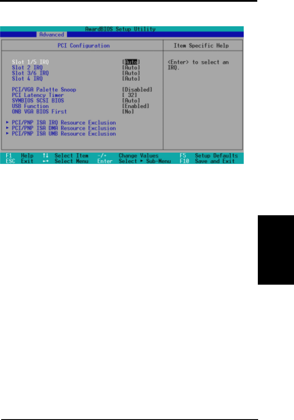
ASUS P3W User’s Manual 67
4. BIOS SETUP
4. BIOS SETUP
Slot 1/5, Slot 2, Slot 3/6, Slot 4 IRQ [Auto]
These fields set how IRQ use is determined for each PCI slot. The default
setting for each field is [Auto], which utilizes auto-routing to determine
IRQ use. Configuration options: [Auto] [NA] [3] [4] [5] [7] [9] [10] [11]
[12] [14] [15]
PCI/VGA Palette Snoop [Disabled]
Some nonstandard VGA cards, such as graphics accelerators or MPEG video
cards, may not show colors properly. The setting [Enabled] should correct
this problem. Otherwise, leave this on the default setting of [Disabled].
Configuration options: [Disabled] [Enabled]
PCI Latency Timer [32]
Leave on default setting for best performance vs. stability.
SYMBIOS SCSI BIOS [Auto]
[Auto] allows the motherboard’s BIOS to detect whether you have a Symbios
SCSI card. If the Symbios SCSI card is detected, the motherboard’s Symbios
BIOS will be enabled; if no Symbios SCSI card is detected, the onboard
Symbios SCSI BIOS will be disabled.
[Disabled] will disable the motherboard’s Symbios SCSI BIOS so that the
BIOS on an external Symbios SCSI card can be used. If your Symbios SCSI
card does not have a BIOS, the Symbios SCSI card will not function. Con-
figuration options: [Auto] [Disabled]
4.4.3 PCI Configuration
PCI Configuration
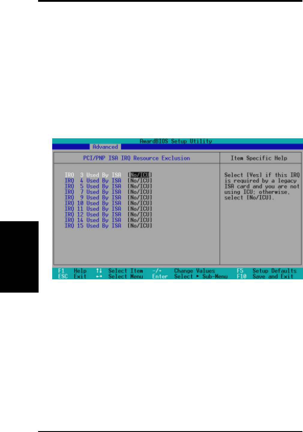
ASUS P3W User’s Manual68
4. BIOS SETUP
4. BIOS SETUP
USB Function [Enabled]
This motherboard supports Universal Serial Bus (USB) devices. Set to [En-
abled] if you want to use USB devices. Configuration options: [Disabled]
[Enabled]
ONB VGA BIOS First [No]
This field, when set to [Yes], gives priority to the onboard VGA BIOS over
other VGA controllers. Configuration options: [No] [Yes]
IRQ XX Used By ISA
These fields indicate whether or not the displayed IRQ for each field is
being used by a legacy (non-PnP) ISA card. The default value indicates
either that the displayed IRQ is not used or that ISA Configuration Utility
(ICU) is being used to determine if an ISA card is using that IRQ. If you
install a legacy ISA card that requires a unique IRQ and you are not using an
ICU, you must set the field for that IRQ to [Yes]. For example: If you install
a legacy ISA card that requires IRQ 10, then set IRQ10 Used By ISA to
[Yes]. Configuration options: [No/ICU] [Yes]
PCI/PNP ISA IRQ Resource Exclusion
PCI Configuration
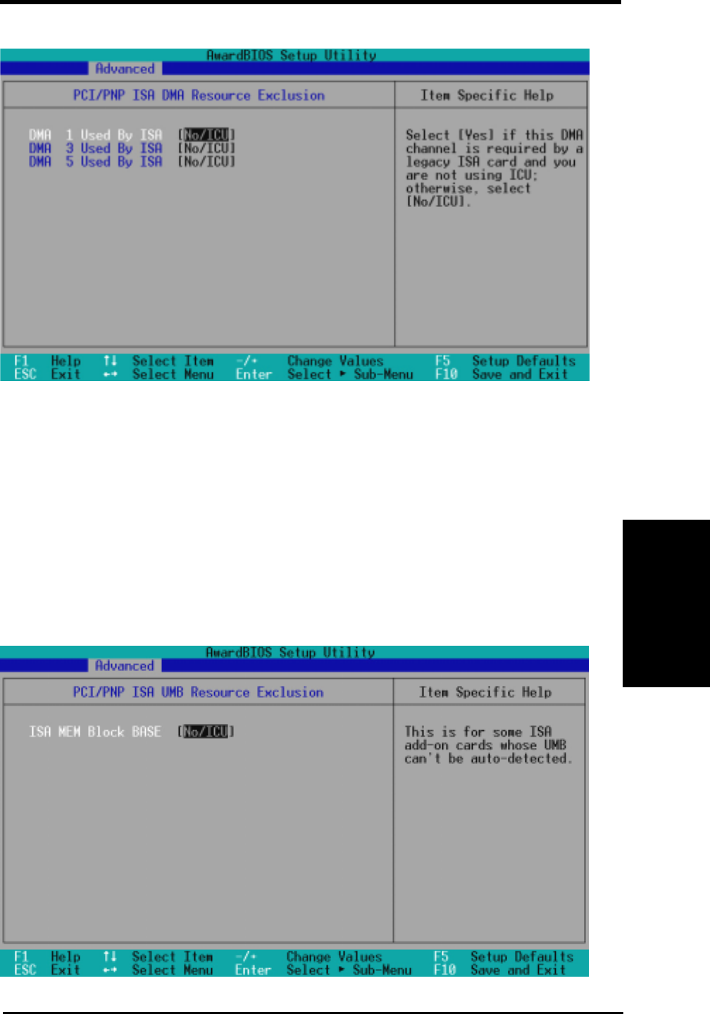
ASUS P3W User’s Manual 69
4. BIOS SETUP
4. BIOS SETUP
DMA x Used By ISA [No/ICU]
These fields indicate whether or not the displayed DMA channel for each
field is being used by a legacy (non-PnP) ISA card. The default setting indi-
cates either that the displayed DMA channel is not used or an ICU is being
used to determine if an ISA card is using that channel. If you install a legacy
ISA card that requires a unique DMA channel, and you are not using an
ICU, you must set the field for that channel to [Yes]. Configuration options:
[No/ICU] [Yes]
PCI/PNP ISA DMA Resource Exclusion
PCI/PNP ISA UMB Resource Exclusion
PCI Configuration
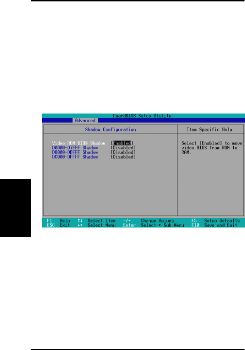
ASUS P3W User’s Manual70
4. BIOS SETUP
4. BIOS SETUP
Video ROM BIOS Shadow [Enabled]
This field allows you to change the video BIOS location from ROM to
RAM. Relocating to RAM enhances system performance, as information
access is faster than the ROM. Configuration options: [Disabled] [Enabled]
D0000-DFFFF Shadow [Disabled]
These fields are used for shadowing other expansion card ROMs. If you
install other expansion cards with ROMs on them, you will need to know
which addresses the ROMs use to shadow them specifically. Shadowing a
ROM reduces the memory available between 640K and 1024K by the amount
used for this purpose. Configuration options: [Disabled] [Enabled]
ISA MEM Block BASE [No/ICU]
This field allows you to set the base address and block size of a legacy ISA
card that uses any memory segment within the C800 and DFFF address
range. If you have such a card and you are not using an ICU to specify its
address range, select a base address from the six available options; the ISA
MEM Block SIZE field will then appear for selecting the block size. If you
have more than one legacy ISA card in your system that requires the use of
this address range, you can increase the block size to 8K, 16K, 32K, or 64K.
If you are using an ICU to accomplish this task, leave ISA MEM Block
BASE to its default setting of [No/ICU]. Configuration options: [No/ICU]
[C800] [CC00] [D000] [D400] [D800] [DC00]
4.4.4 Shadow Configuration
Shadow Configuration
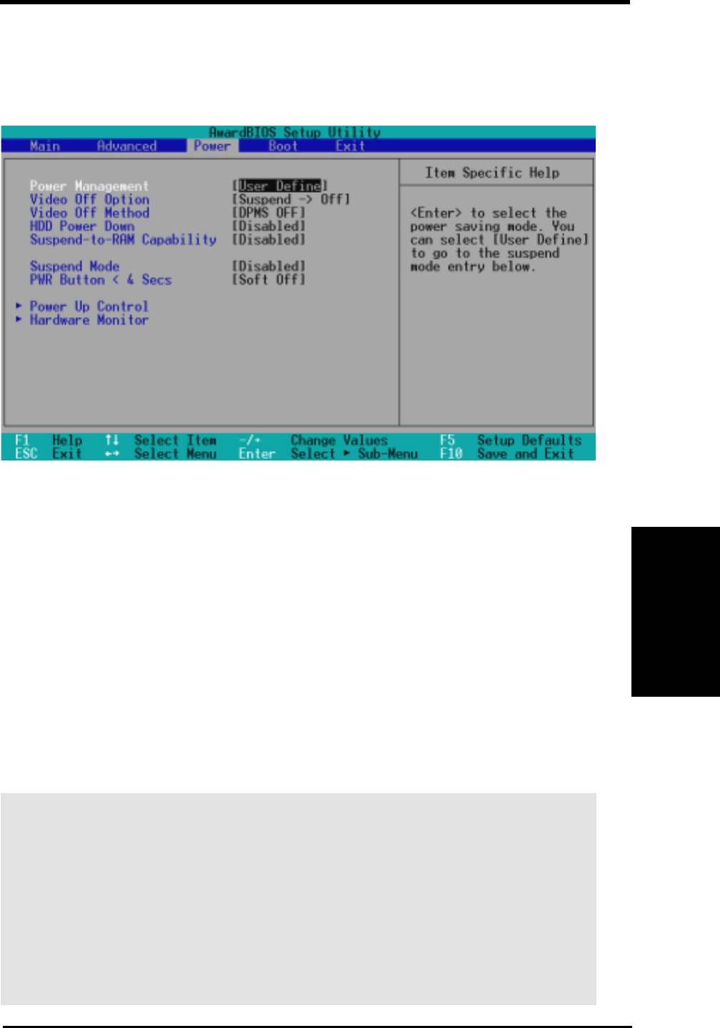
ASUS P3W User’s Manual 71
4. BIOS SETUP
4. BIOS SETUP
4.5 Power Menu
The Power menu allows you to reduce power consumption. This feature turns off the
video display and shuts down the hard disk after a period of inactivity.
Power Management [User Define]
This option must be enabled to use any of the automatic power saving features. If
this menu item is set to [Disabled], power management features will not function
regardless of other field settings on this menu. The [User Define] option allows you
to make your own selections in the Power menu. When set to [Max Saving], system
power will be conserved to its greatest amount. The Suspend Mode field will then
be set to predefined value that ensures maximum power savings.
This field acts as the master control for the power management modes. [Max Sav-
ing] puts the system into power saving mode after a brief period of system inactiv-
ity; [Min Saving] is almost the same as [Max Saving] except that the system inactiv-
ity period is longer; [Disabled] disables the power saving features; [User Define]
allows you to set power saving options according to your preference. Configuration
options: [User Define] [Disabled] [Min Saving] [Max Saving]
IMPORTANT: Advanced Power Management (APM) should be installed to keep
the system time updated when the computer enters suspend mode activated by
the BIOS Power Management. For DOS environments, you need to add the
statement, DEVICE=C:\DOS\POWER.EXE, to your CONFIG.SYS file. For
Windows 3.x and Windows 95, you need to install Windows with the APM
feature. For Windows 98 and later, APM is automatically installed. A battery
and power cord icon labeled “Power Management” will appear in the “Control
Panel.” Choose “Advanced” in the Power Management Properties dialog box.
Power Menu

ASUS P3W User’s Manual72
4. BIOS SETUP
4. BIOS SETUP
Video Off Option [Suspend -> Off ]
This field determines when to activate the video off feature for monitor
power management. Configuration options: [Always On] [Suspend -> Off]
Video Off Method [DPMS OFF]
This field defines the video off features. The DPMS (Display Power Manage-
ment System) feature allows the BIOS to control the video display card if it
supports the DPMS feature. [Blank Screen] only blanks the screen (use this
for monitors without power management or “green” features. If set up in your
system, your screen saver will not display with [Blank Screen] selected). [V/
H SYNC+Blank] blanks the screen and turns off vertical and horizontal scan-
ning. Configuration options: [Blank Screen] [V/H SYNC+Blank] [DPMS
Standby] [DPMS Suspend] [DPMS OFF] [DPMS Reduce ON]
HDD Power Down [Disabled]
Shuts down any IDE hard disk drives in the system after a period of inac-
tivity as set in this user-configurable field. This feature does not affect
SCSI hard drives. Configuration options: [Disabled] [1 Min] [2 Min] [3
Min]...[15 Min]
Suspend-to-RAM Capability [Disabled]
Suspend-to-RAM (STR) is an energy-saving feature. In Suspend-to-RAM
state, all devices on the computer are turned off, except for the system
RAM. Thus, the PC consumes less than 5 Watts of power. [Auto] allows
the BIOS to detect if your power supply can supply at least 720mA on the
+5VSB lead to support the STR function. If the power supply meets the
requirement, the STR function will be enabled; if not, this function will be
disabled. If the expansion cards you use on the motherboard do not support
the STR function, you must leave this field on the default setting [Disabled].
Configuration options: [Auto] [Disabled]
Suspend Mode [Disabled]
Sets the time period before the system goes into suspend mode. Configu-
ration options: [Disabled] [1~2 Min] [2~3 Min] [4~5 Min] [8~9 Min] [20
Min]...[1 Hour]
PWR Button < 4 Secs [Soft off]
When set to [Soft off], the ATX switch can be used as a normal system
power-off button when pressed for less than 4 seconds. [Suspend] allows
the button to have a dual function where pressing less than 4 seconds will
place the system in sleep mode. Regardless of the setting, holding the ATX
switch for more than 4 seconds will power off the system. Configuration
options: [Soft off] [Suspend]
Power Menu

ASUS P3W User’s Manual 73
4. BIOS SETUP
4. BIOS SETUP
AC PWR Loss Restart [Disabled]
This allows you to set whether you want your system to reboot after the
power has been interrupted. [Disabled] leaves your system off and [En-
abled] reboots your system. Configuration options: [Disabled] [Enabled]
PWR Up On Modem Act [Disabled]
This allows either settings of [Enabled] or [Disabled] for powering up the
computer when the modem receives a call while the computer is in Soft-off
mode. NOTE: The computer cannot receive or transmit data until the com-
puter and applications are fully running. Thus connection cannot be made
on the first try. Turning an external modem off and then back on while the
computer is off causes an initialization string that will also cause the system
to power on. Configuration options: [Disabled] [Enabled]
Wake On LAN [Enabled]
Wake-On-LAN allows your computer to be booted from another computer
via a network by sending a wake-up frame or signal. Configuration options:
[Disabled] [Enabled]
IMPORTANT: This feature requires an optional network interface with Wake-
On-LAN and an ATX power supply with at least 720mA +5V standby power.
4.5.1 Power Up Control
Power Up Control

ASUS P3W User’s Manual74
4. BIOS SETUP
4. BIOS SETUP
Power Up Control
Wake On PS2 KB/Mouse [Disabled]
Set this field to [Enabled] if you wish to use your PS2 keyboard (by pressing
the spacebar) or PS2 mouse (by clicking on the left button) to power up your
computer. This feature requires an ATX power supply that can supply at least
300mA on the +5VSB lead. The default is set to [Disabled] because not all
computers have the appropriate ATX power supply. Your computer will not
power ON if you set this to [Enabled] and do not have the appropriate ATX
power supply. Configuration options: [Disabled] [Enabled]
Automatic Power Up [Disabled]
This allows an unattended or automatic system power up. You may configure
your system to power up at a certain time of the day by selecting [Everyday] or
at a certain time and day by selecting [By Date]. Configuration options: [Dis-
abled] [Everyday] [By Date]
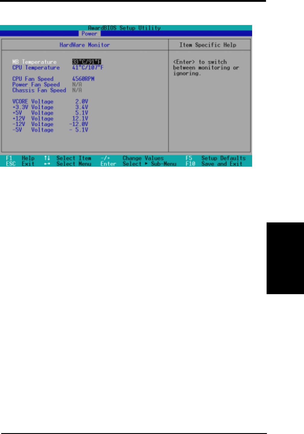
ASUS P3W User’s Manual 75
4. BIOS SETUP
4. BIOS SETUP
4.5.2 Hardware Monitor
MB Temperature, CPU Temperature [xxxC/xxxF]
The onboard hardware monitor is able to detect the MB (motherboard) and
CPU temperatures. Set to [Ignore] only if necessary.
CPU Fan, Power Fan, Chassis Fan Speed [xxxxRPM]
The onboard hardware monitor is able to detect the CPU fan speed, power
supply fan speed, and the chassis fan speed in rotations per minute (RPM).
The presence of the fans is automatically detected. Set to [Ignore] only if
necessary.
VCORE Voltage, +3.3V Voltage, +5V Voltage, +12V Voltage,
-12V Voltage, -5V Voltage [xx.xV]
The onboard hardware monitor is able to detect the voltage output by the
onboard voltage regulators. Set to [Ignore] only if necessary.
NOTE: If any of the monitored items is out of range, an error message will
appear: “Hardware Monitor found an error. Enter Power setup menu for
details”. You will then be prompted to “Press F1 to continue, DEL to enter
SETUP”.
Hardware Monitor
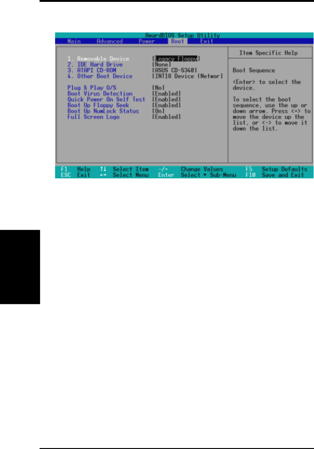
ASUS P3W User’s Manual76
4. BIOS SETUP
4. BIOS SETUP
Boot Menu
Boot Sequence
The Boot menu allows you to select among the four possible types of boot
devices listed using the up and down arrow keys. By using the <+> or <Space>
key, you can promote devices and by using the <-> key, you can demote
devices. Promotion or demotion of devices alters the priority which the sys-
tem uses to search for a boot device on system power up. Configuration op-
tions: [Removable Devices] [IDE Hard Drive] [ATAPI CD-ROM] [Other
Boot Device]
Removable Device [Legacy Floppy]
Configuration options: [Legacy Floppy] [LS120] [ZIP-100] [ATAPI MO]
IDE Hard Drive
This field allows you to select which IDE hard disk drive to use in the boot
sequence. Pressing [Enter] will show the product IDs of all connected IDE
hard disk drives.
ATAPI CD-ROM
This field allows you to select which ATAPI CD-ROM drive to use in the
boot sequence. Pressing [Enter] will show the product IDs of all your con-
nected ATAPI CD-ROM drives.
Other Boot Device Select [Network]
Configuration options: [Network] [SCSI Boot Device]
4.6 Boot Menu

ASUS P3W User’s Manual 77
4. BIOS SETUP
4. BIOS SETUP
Plug & Play O/S [No]
This field allows you to use a Plug-and-Play (PnP) operating system to con-
figure the PCI bus slots instead of using the BIOS. When [Yes] is selected,
interrupts may be reassigned by the OS. When a non-PnP OS is installed or
you want to prevent reassigning of interrupt settings, select the default set-
ting of [No]. Configuration options: [No] [Yes]
Boot Virus Detection [Enabled]
Configuration options: [Disabled] [Enabled]
Quick Power On Self Test [Enabled]
Configuration options: [Disabled] [Enabled]
Boot Up Floppy Seek [Enabled]
Configuration options: [Disabled] [Enabled]
Boot Up NumLock Status [On]
Configuration options: [Off] [On]
Full Screen Logo [Enabled]
Configuration options: [Disabled] [Enabled]
Boot Menu
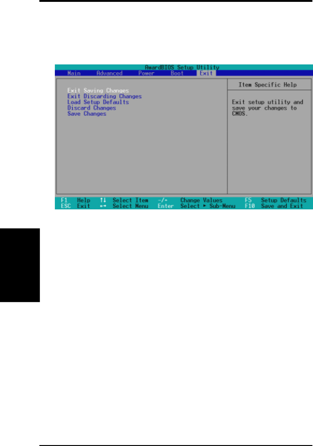
ASUS P3W User’s Manual78
4. BIOS SETUP
4. BIOS SETUP
Exit Menu
Exit Saving Changes
Once you are finished making your selections, choose this option from the
Exit menu to ensure the values you selected are saved to the CMOS RAM.
The CMOS RAM is sustained by an onboard backup battery and stays on
even when the PC is turned off. Once this option is selected, a confirmation
is asked. Select [Yes] to save changes and exit.
NOTE: If you attempt to exit the Setup program without saving your
changes, the program will prompt you with a message asking if you want
to save your changes before exiting. Pressing <Enter> will then save changes
while exiting.
Exit Discarding Changes
This option should only be used if you do not want to save the changes you
have made to the Setup program. If you have made changes to fields other
than system date, system time, and password, the system will ask for con-
firmation before exiting.
4.7 Exit Menu
Once you have made all of your selections from the various menus in the Setup pro-
gram, you should save your changes and exit Setup. Select Exit from the menu bar to
display the following menu:
NOTE: Pressing <Esc> does not exit this menu. You must select one of the
options from this menu or <F10> from the legend bar to exit this menu.

ASUS P3W User’s Manual 79
4. BIOS SETUP
4. BIOS SETUP
Load Setup Defaults
This option allows you to load the default values for each of the parameters
on the Setup menus. When this option is selected or if <F5> is pressed, a
confirmation is requested. Select [Yes] to load default values. You can now
select Exit Saving Changes or make other changes before saving the val-
ues to the non-volatile RAM.
Discard Changes
This option allows you to discard the selections you made and restore the
values you previously saved. After selecting this option, a confirmation is
requested. Select [Yes] to discard any changes and load the previously saved
values.
Save Changes
This option saves your selections without exiting the Setup program. You
can then return to other menus and make changes. After selecting this op-
tion, all selections are saved and a confirmation is requested. Select [Yes] to
save any changes to the non-volatile RAM.
Exit Menu

ASUS P3W User’s Manual80
4. BIOS SETUP
4. BIOS SETUP
(This page was intentionally left blank.)
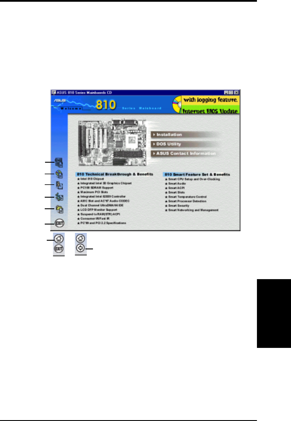
ASUS P3W User’s Manual 81
5. SOFTWARE SETUP
5. S/W SETUP
Windows 98
5.1 ASUS Smart Motherboard Support CD
NOTE: The support CD contents are subject to change at any time without notice.
To begin using your support CD disc, just insert it into your CD-ROM drive and the
support CD installation menu should appear. If the menu does not appear, double
click or run D:\ASSETUP.EXE (assuming that your CD-ROM drive is drive D:).
5.1.1 Support CD Main Menu
Navigation Button Descriptions
Motherboard Info displays information on your motherboard, BIOS, and CPU.
Browse This CD allows you to see the contents of the ASUS Support CD.
User’s Manual displays the motherboard user’s manual in pdf format.
Technical Support Form opens up a blank Technical Support Request Form for
you to fill and print out when you run into technical difficulties and need technical
assistance.
Read Me opens up a file containing additional notes.
Home returns you to the main menu of the support CD. (only on other screens)
Exit allows you to close the support CD.
Back returns you one screen back on the support CD.
Motherboard Info
Browse This CD
User’s Manual
Technical Support Form
Read Me
Exit
Main Menu (home button
only on other screens) Back (arrow button only
on certain screens)
5. SOFTWARE SETUP
81
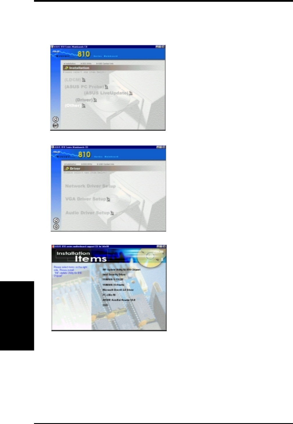
82 ASUS P3W User’s Manual
5. SOFTWARE SETUP
5. S/W SETUP
Windows 98
5.1.2 Support CD Submenus
NOTE: The support CD contents are subject to change at any time without notice.
Installation Submenu LDCM: Installs software to monitor PC system(s).
ASUS Probe: Installs a simple utility to monitor your
computer’s fan, temperature, and voltages.
ASUS LiveUpdate: Installs a program to help you
update your BIOS or download a BIOS image file.
Driver: Installs the necessary drivers for your on-
board components to work properly.
Other: Allows you to install additional software and
utilities to help you make better use of your new
motherboard.
Driver
Network Driver Setup: Not available on this moth-
erboard.
VGA Driver Setup: Intel’s 810 DC-100 System and
Graphics Controller Driver.
Audio Driver Setup: Not available on this mother-
board.
Other
INF Update Utility for 810 Chipset: This utility in-
stalls INF files in Windows for the following items:
System and Graphics, LPC Interface, SM Bus, PCI
Bridge, Bus Master IDE, USB Host, Controllers
Intel Security Driver: Installs a security controller
for your Windows 95/98. Read the Release Notes dur-
ing installation and the Readme file at the end of the
installation for more information.
YAMAHA S-YXG50: Installs Yamaha’s software
synthesizer for playing MIDI files on a personal com-
puter through software alone without usinga hard-
ware sound source such as a sound card. (YAMAHA, Soft Synthesizer, S-YXG50, Midplug, and XG
studio are all trademarks of Yamaha Corp. Copyright 1996-1999 Yamaha Corporation, All Rights Re-
served)
YAMAHA XGStudio: Installs Yamaha’s XGStudio Mixer.
Microsoft DirectX 6.0 Driver: Installs Microsoft’s DirectX 6.0 driver for Windows 95/98. Microsoft’s
DirectX is necessary for most multimedia applications to run.
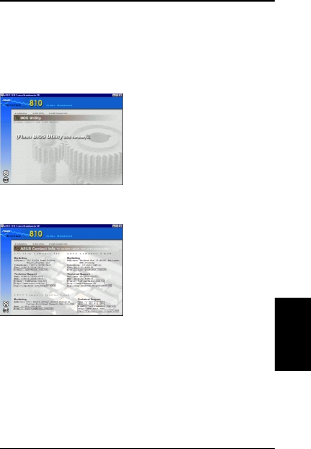
ASUS P3W User’s Manual 83
5. SOFTWARE SETUP
5. S/W SETUP
Windows 98
DOS Utility Submenu
ASUS Contact Information Submenu
PC-cillin 98: Installs Trend’s PC-cillin virus protection software. View the online help for more informa-
tion.
Adobe Acrobat Reader: Installs the Adobe Acrobat Reader software necessary to view user’s manuals
saved in PDF format. Updated or other language versions of this motherboard's manual is available in
PDF format at any of our web sites.
Exit: Returns to the Installation menu.
Flash BIOS Utility (DOS Version): Provides infor-
mation on the Flash BIOS utility (AFLASH.EXE).
Choose “Restart in MS-DOS mode” then type
“aflash” from the AFLASH folder on the support CD.
This page gives Marketing and Technical Support
contact information which is similar to the one in
the beginning of this User’s Manual.

84 ASUS P3W User’s Manual
5. SOFTWARE SETUP
5. S/W SETUP
Windows 98
5.2 Operating Systems
Although ASUS motherboards passed testing on several operating systems, the op-
erating system shown in these sections will be that of Microsoft’s Windows 98. You
should always use the latest operating system and updates when using new hard-
ware to ensure full compliancy. For Windows 95, you must use OSR 2.0 or later. For
Windows NT 4.0, you must use Service Pack 3.0 or later.
5.3 Starting Windows For the First Time
When you start Windows 98 for the first time after installing your motherboard,
Windows will detect all plug-and-play devices. You can either follow the Add New
Hardware Wizard to install the device drivers or click Cancel. When prompted to
restart, select No and then follow the normal setup procedures later in this section.
IMPORTANT: Selecting No for the initial restart prompt is a necessary step
because Windows may load an older display driver that is incompatible with the
onboard VGA chip. Always use the driver available on the ASUS Support CD or
an applicable driver update from your ASUS vendor or from the ASUS web site.
NOTE: Because there are various motherboard settings, options, and expansion
cards, the following can only be used as a general reference and not an exact reflec-
tion of your system.
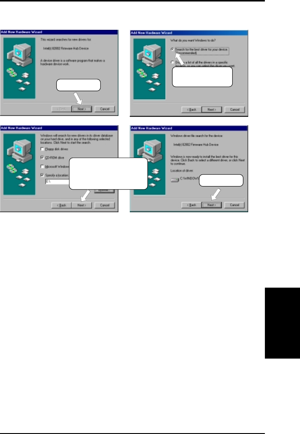
ASUS P3W User’s Manual 85
5. SOFTWARE SETUP
5. S/W SETUP
Windows 98
5.3.1 Intel 82802 Firmware Hub Device Found
(2) Click here and
then click Next.
(1) Click here.
(3) Insert the Windows 98
CD into your CD-ROM
drive, browse to it, and
then click here. (4) Click here.
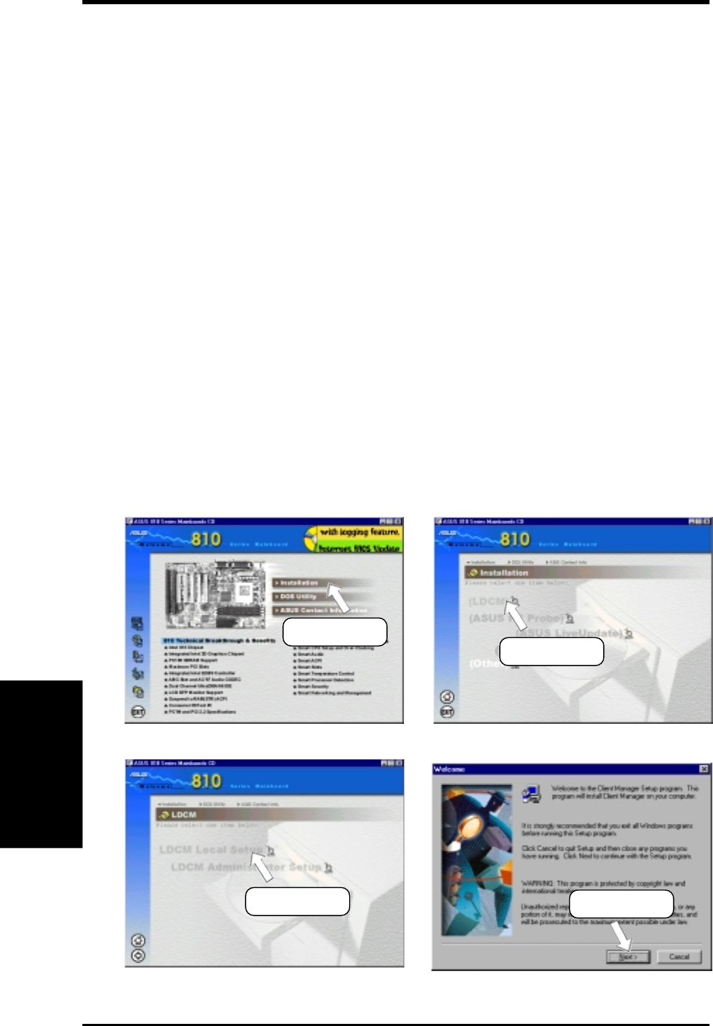
86 ASUS P3W User’s Manual
5. SOFTWARE SETUP
5. S/W SETUP
Windows 98
5.4 LDCM Local Setup
System Requirements
•Intel® Pentium® microprocessor or higher.
•Operating system: Microsoft Windows 95 (can be OEM Service Release 2), or
Windows 98, or Windows NT 4.0 (Service Pack 4 or later).
•Microsoft Internet Explorer 4.01 or higher.
•Memory: 16 MB of RAM for Windows 95/98; 24 MB of RAM for Windows NT
(32 MB recommended).
•Disk storage space: 100 MB of available hard disk space to install; 40-100 MB
of available hard disk space to run (depending on cluster size).
•Hardware system: DM or SM BIOS is required for full LDCM functionality.
•Protocols: IP (Winsock-enabled) communication protocol loaded on the client.
An IP stack is required on the client, regardless of whether the client accesses
the network.
•Monitor resolution of 600x800, 256 colors or greater.
Insert the Support CD that came with your motherboard into your CD-ROM drive
or double-click the CD drive icon in My Computer to bring up the setup screen.
NOTE: LDCM will not run if another hardware monitoring utility, such as ASUS
PC Probe, is installed. To uninstall any program, see 5.10 Uninstalling Programs.
(1) Click here. (2) Click here.
(3) Click here. (4) Click here.
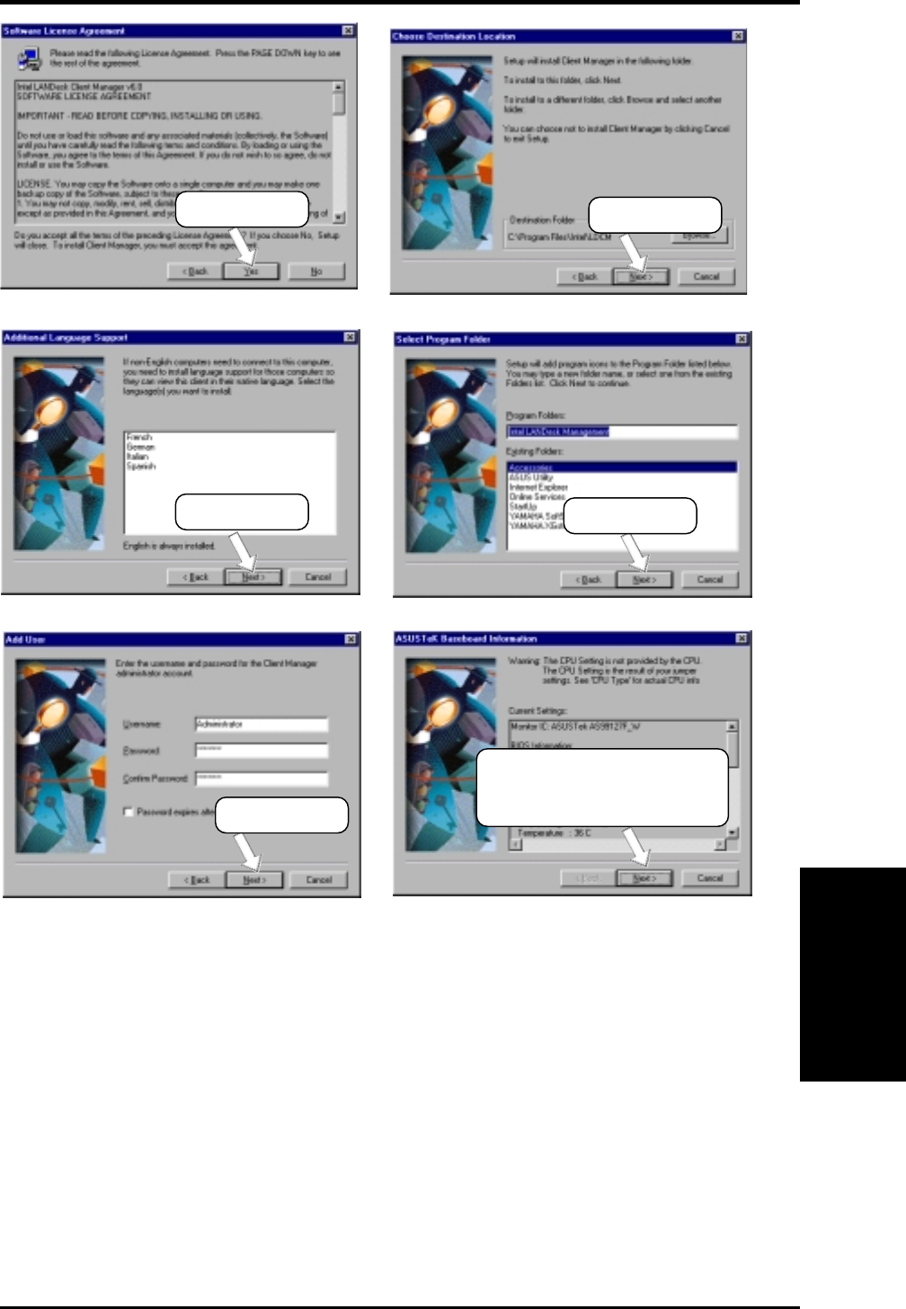
ASUS P3W User’s Manual 87
5. SOFTWARE SETUP
5. S/W SETUP
Windows 98
(7) Click here. (8) Click here.
(9) Click here.
(10) Click here and then follow
the online instruction to
finish installing.
(5) Click here. (6) Click here.
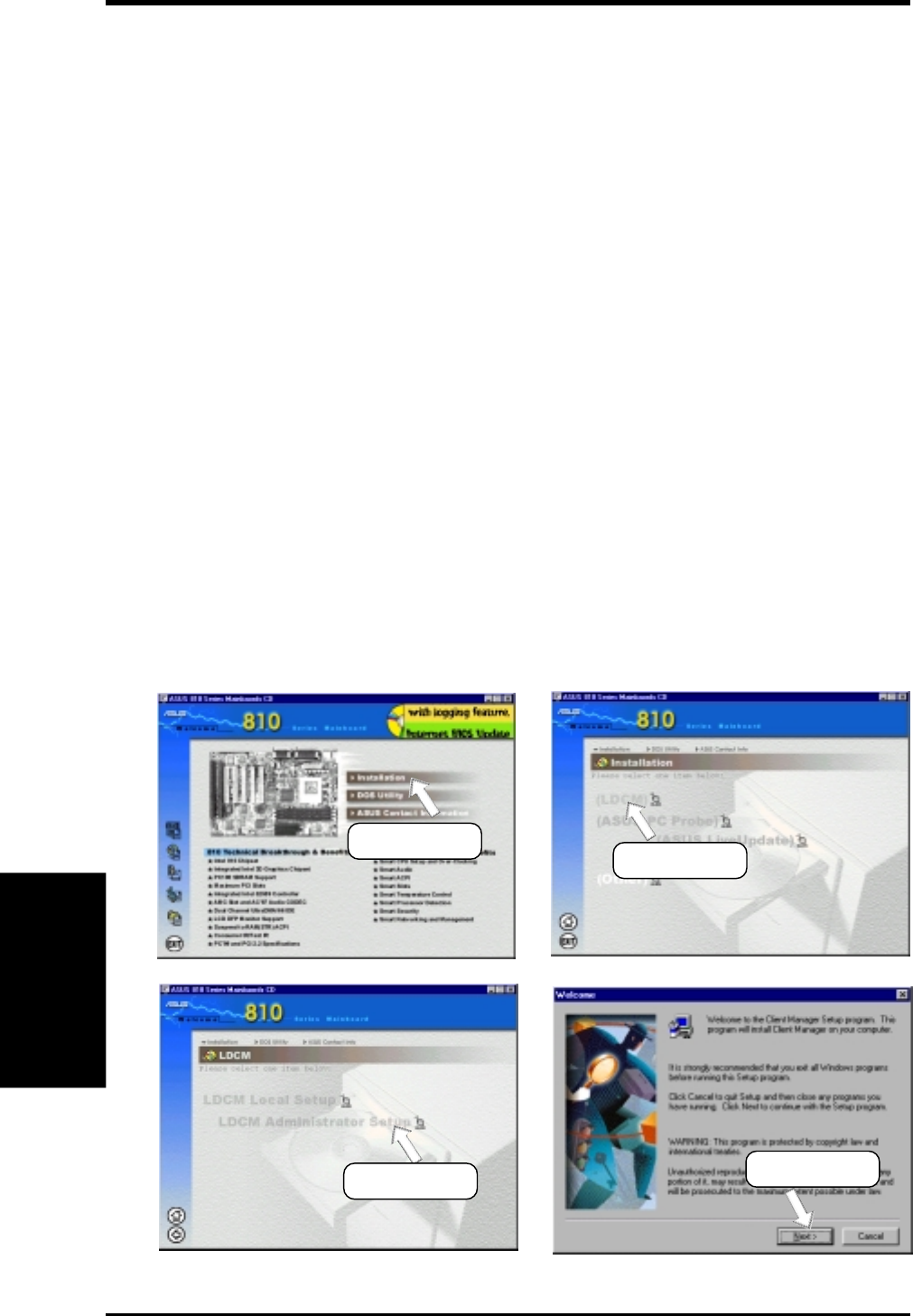
88 ASUS P3W User’s Manual
5. SOFTWARE SETUP
5. S/W SETUP
Windows 98
5.5 LDCM Administrator Setup
System Requirements
•Intel® Pentium® microprocessor or higher.
•Operating system: Microsoft Windows 95 (can be OEM Service Release 2), or
Windows 98, or Windows NT 4.0 (Service Pack 4 or later).
•Microsoft Internet Explorer 4.01 or higher.
•Memory: 16 MB of RAM for Windows 95/98; 24 MB of RAM for Windows NT
(32 MB recommended).
•Disk storage space: 100 MB of available hard disk space to install; 40-100 MB
of available hard disk space to run (depending on cluster size).
•Hardware system: DM or SM BIOS is required for full LDCM functionality.
•Protocols: IP (Winsock-enabled) communication protocol loaded on the client.
An IP stack is required on the client, regardless of whether the client accesses
the network.
•Monitor resolution of 600x800, 256 colors or greater.
Insert the Support CD that came with your motherboard into your CD-ROM drive
or double-click the CD drive icon in My Computer to bring up the setup screen.
NOTE: LDCM will not run if another hardware monitoring utility, such as ASUS
PC Probe, is installed. To uninstall any program, see 5.10 Uninstalling Programs.
(1) Click here. (2) Click here.
(3) Click here. (4) Click here.
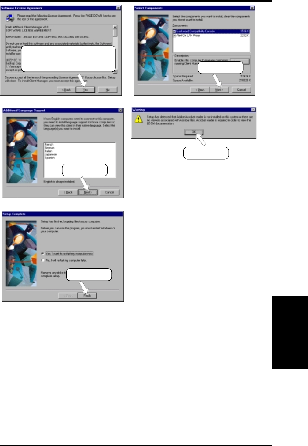
ASUS P3W User’s Manual 89
5. SOFTWARE SETUP
5. S/W SETUP
Windows 98
(7) Click here.
(9) Click here.
(8) Click here.
(5) Click here only after you have
carefully read the license
agreement. (6) Click here.
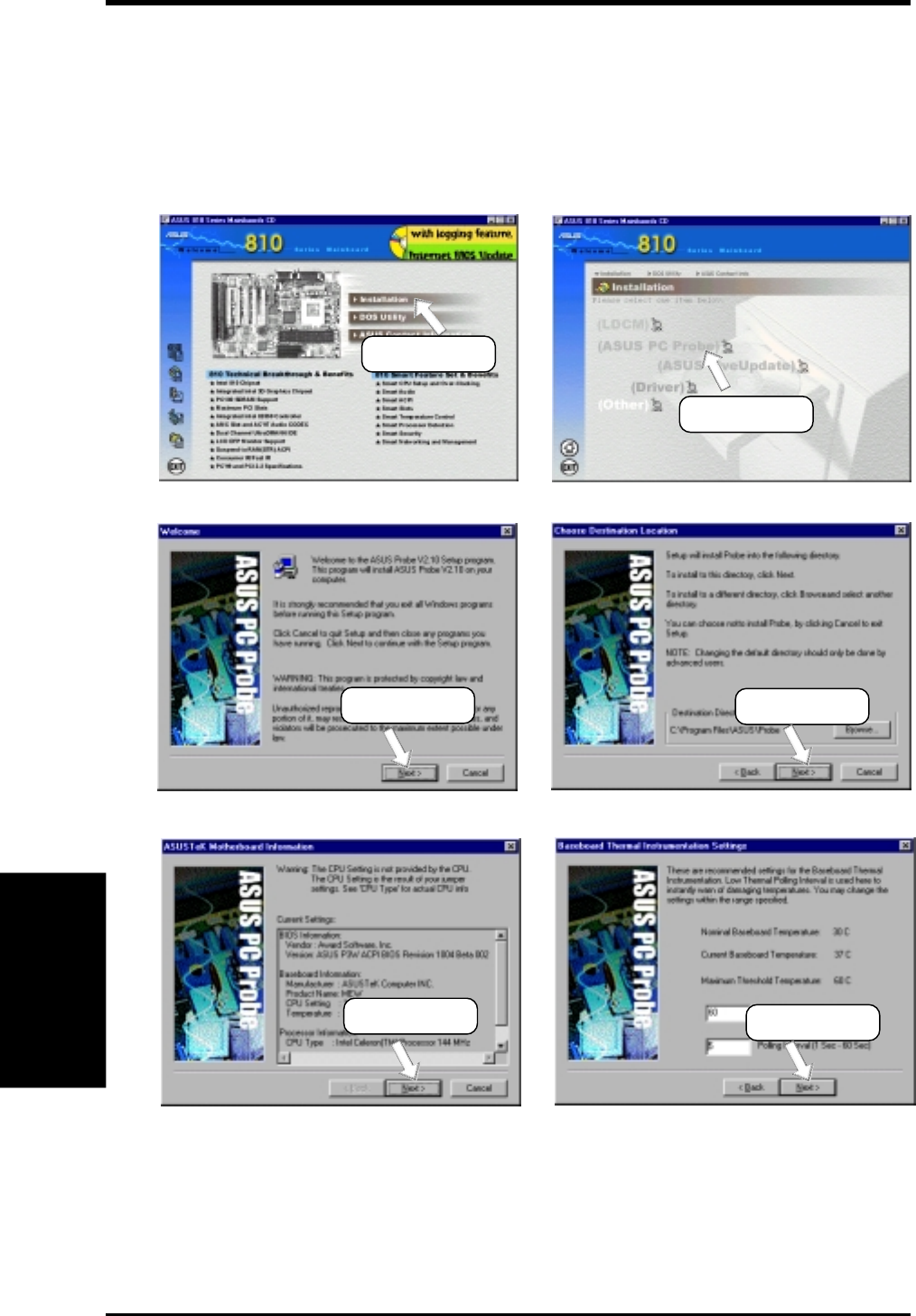
90 ASUS P3W User’s Manual
5. SOFTWARE SETUP
5. S/W SETUP
Windows 98
5.6 ASUS PC Probe
Insert the Support CD that came with your motherboard into your CD-ROM drive
or double-click the CD drive icon in My Computer to bring up the setup screen.
NOTE: ASUS PC Probe will not run if another hardware monitoring utility, such as
LDCM, is installed. To uninstall any program, see 5.10 Uninstalling Programs.
(1) Click here.
(2) Click here.
(3) Click here. (4) Click here.
(5) Click here. (6) Click here.
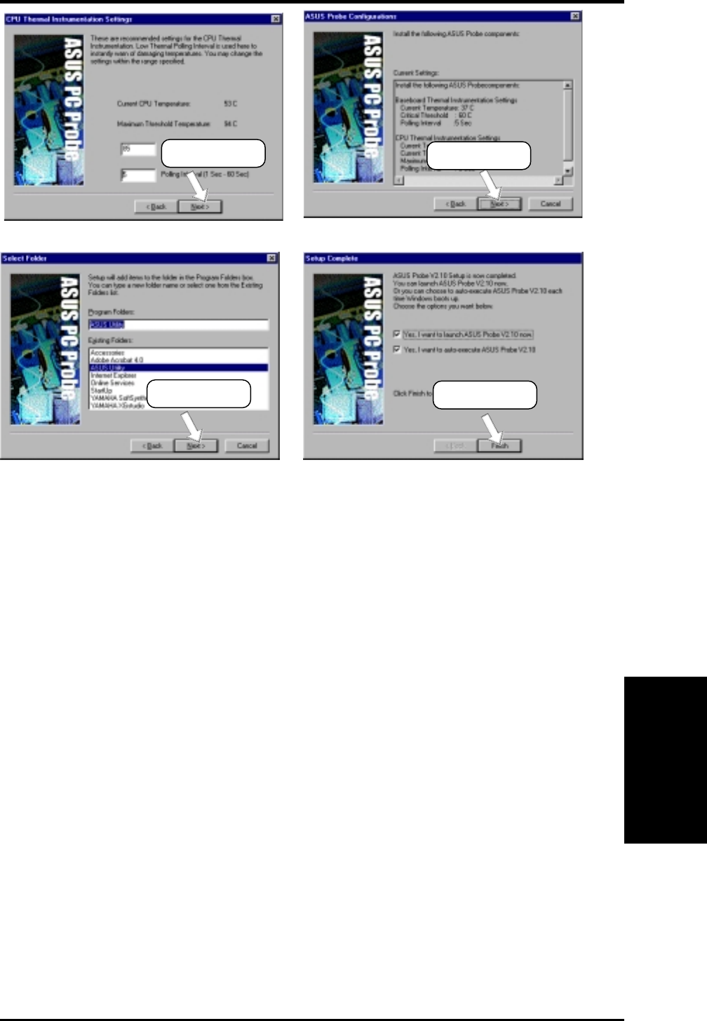
ASUS P3W User’s Manual 91
5. SOFTWARE SETUP
5. S/W SETUP
Windows 98
(7) Click here. (8) Click here.
(9) Click here. (10) Click here.
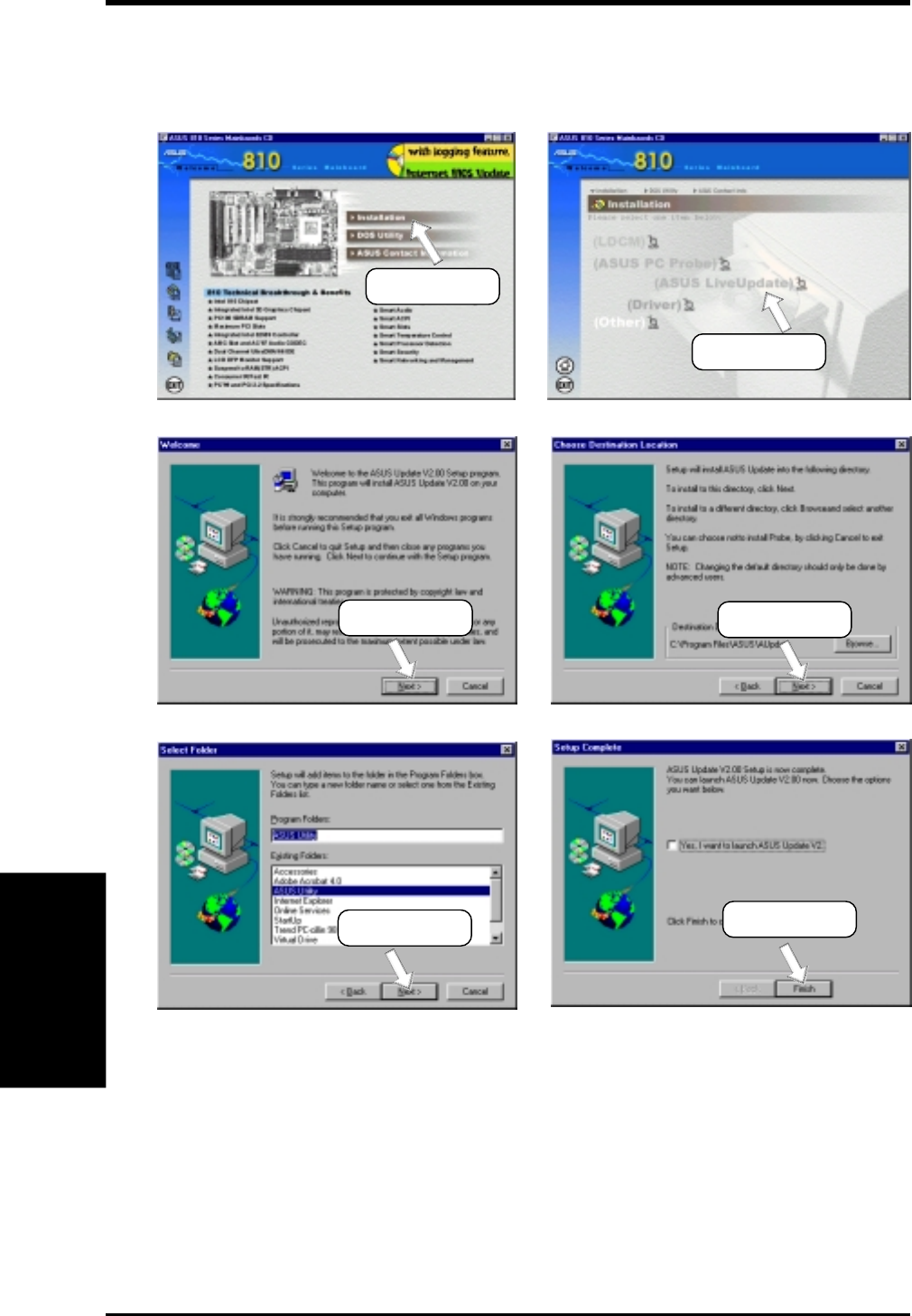
92 ASUS P3W User’s Manual
5. SOFTWARE SETUP
5. S/W SETUP
Windows 98
5.7 ASUS LiveUpdate
Insert the Support CD that came with your motherboard into your CD-ROM drive
or double-click the CD drive icon in My Computer to bring up the setup screen.
(1) Click here.
(2) Click here.
(3) Click here. (4) Click here.
(5) Click here. (6) Click here.
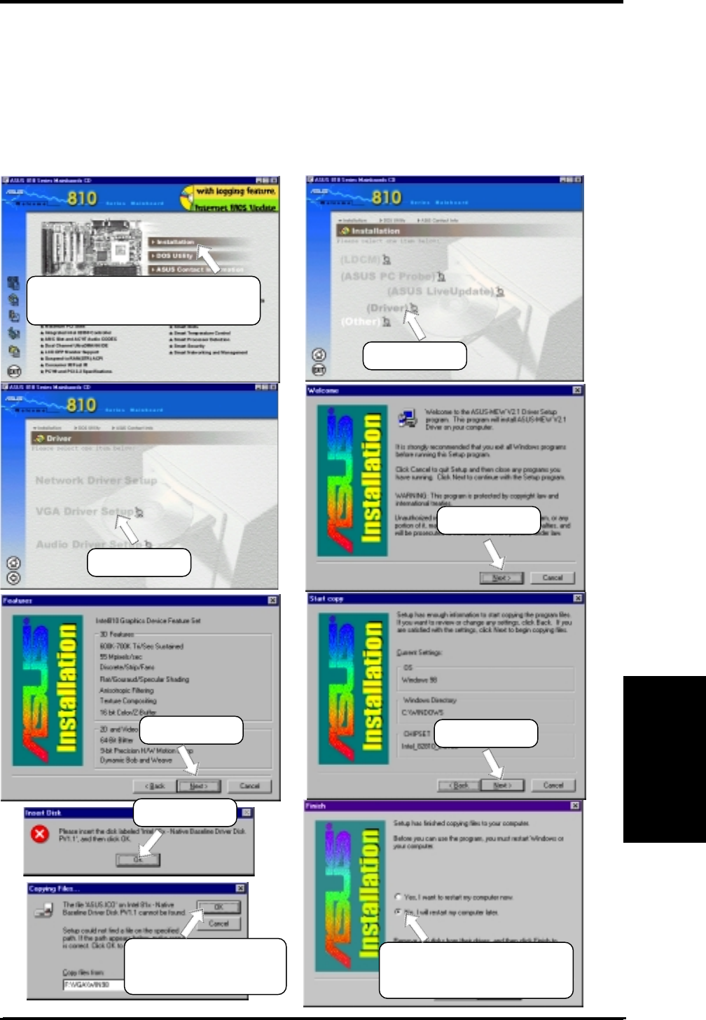
ASUS P3W User’s Manual 93
5. SOFTWARE SETUP
5. S/W SETUP
Windows 98
5.8 Drivers
5.8.1 VGA Driver Setup
Insert the Support CD that came with your motherboard into your CD-ROM drive
or double-click the CD drive icon in My Computer to bring up the setup screen.
NOTE: Before you install the VGA driver, make sure that the INF Update Utility is
installed (see 5.9.1 INF Update Utility for 810 Chipset)
(4) Click here.
(2) Click here.
(3) Click here.
(9) To install other drivers or
software, click here, and
then click Finish.
(1) After your computer has re-
started, double-click the CD
drive icon and then click here.
(8) Browse to
E:\VGA\WIN98 and
then click here.
(5) Click here. (6) Click here.
(7) Click here.
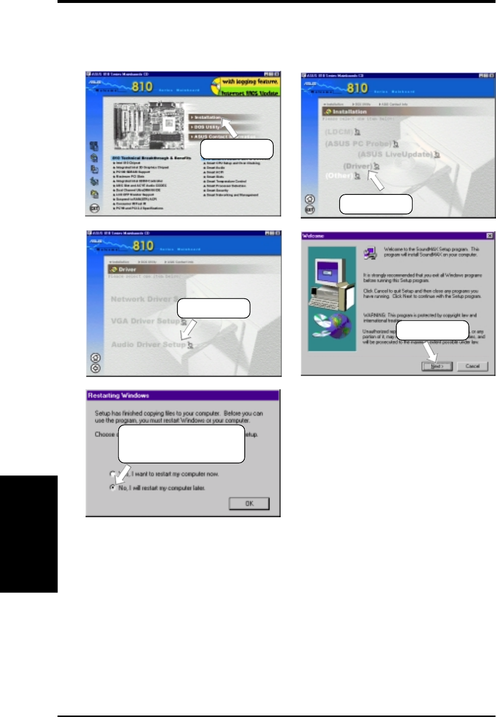
94 ASUS P3W User’s Manual
5. SOFTWARE SETUP
5. S/W SETUP
Windows 98
5.8.2 Audio Driver Setup
Insert the Support CD that came with your motherboard into your CD-ROM drive
or double-click the CD drive icon in My Computer to bring up the setup screen.
(1) Click here.
(2) Click here.
(3) Click here.
(4) Click here.
(5) Click here and then
click OK to install other
drivers and software.
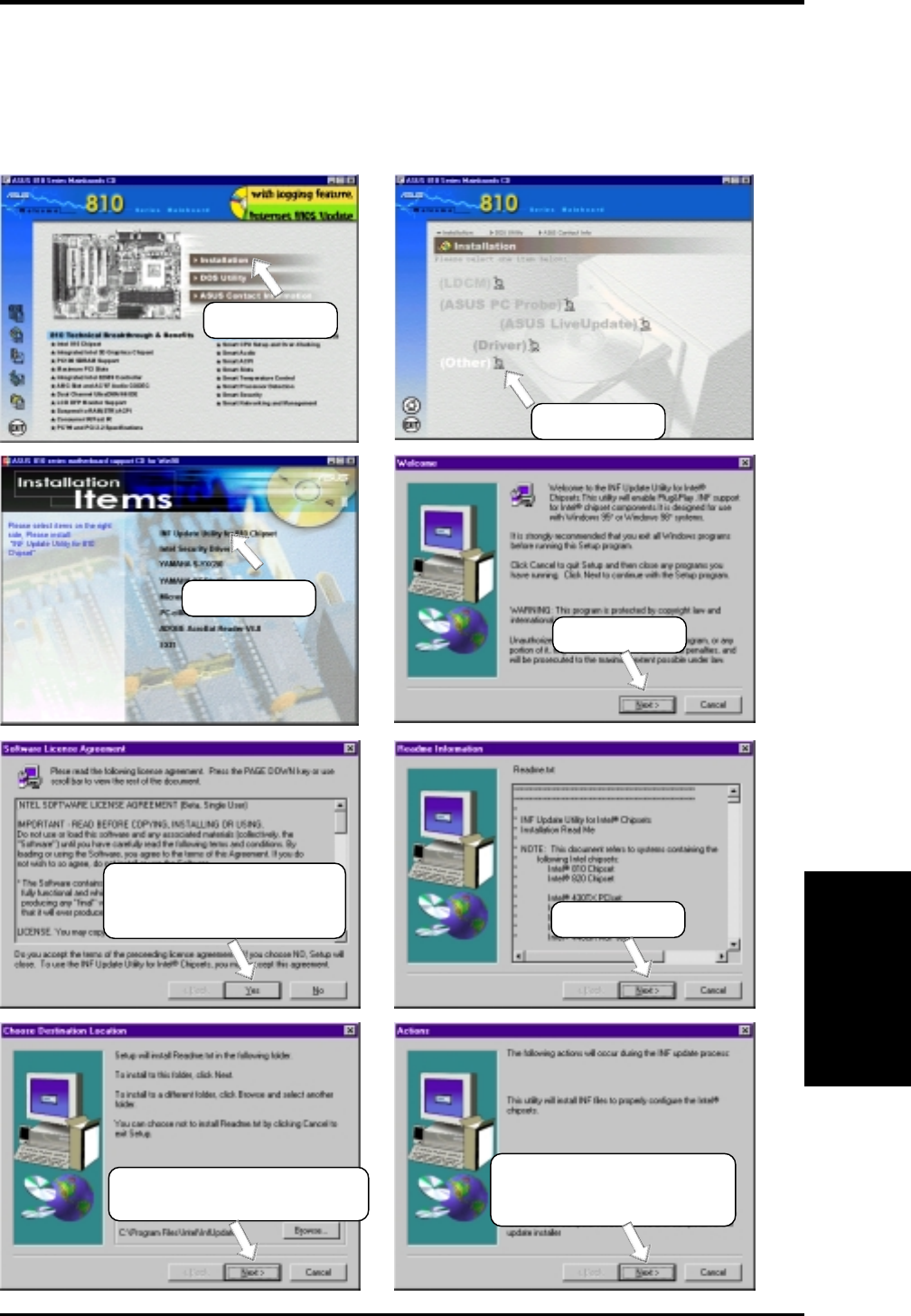
ASUS P3W User’s Manual 95
5. SOFTWARE SETUP
5. S/W SETUP
Windows 98
5.9 Other
5.9.1 INF Update Utility for 810 Chipset
Insert the Support CD that came with your motherboard into your CD-ROM drive
or double-click the CD drive icon in My Computer to bring up the setup screen.
(1) Click here.
(2) Click here.
(3) Click here.
(4) Click here.
(5) Click here only after you
have read the license
agreement. (6) Click here.
(7) Click here to install the
driver to the default folder.
(8) Click here and then follow
the online instructions.
Restart when prompted
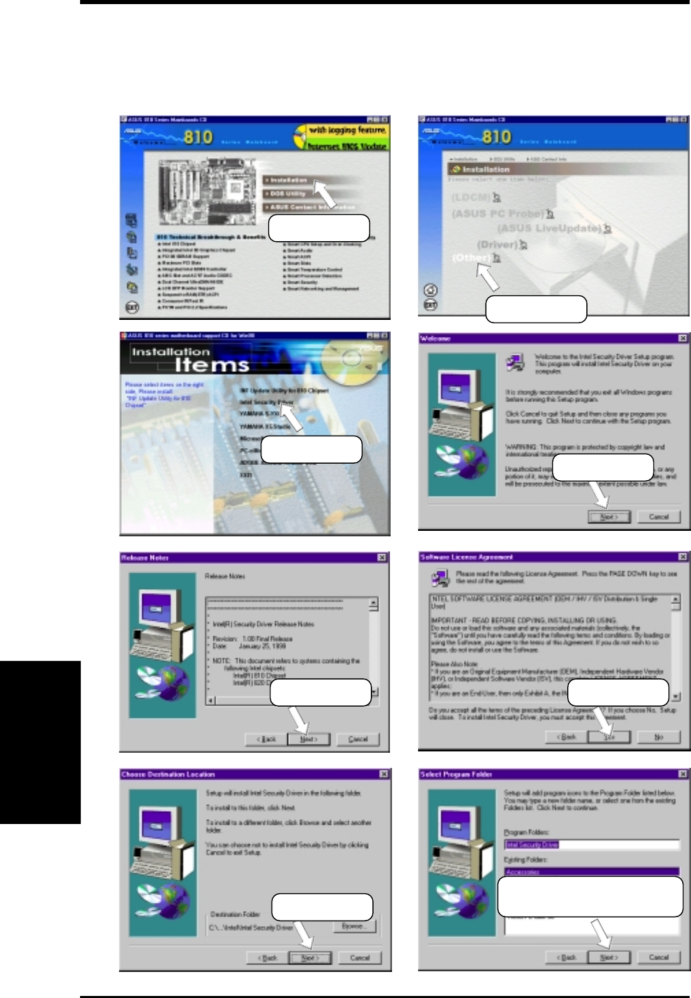
96 ASUS P3W User’s Manual
5. SOFTWARE SETUP
5. S/W SETUP
Windows 98
5.9.2 Intel Security Driver
Insert the Support CD that came with your motherboard into your CD-ROM drive
or double-click the CD drive icon in My Computer to bring up the setup screen.
(1) Click here.
(2) Click here.
(3) Click here. (4) Click here.
(5) Click here. (6) Click here.
(7) Click here. (8) Click here and then follow
the online instructions.
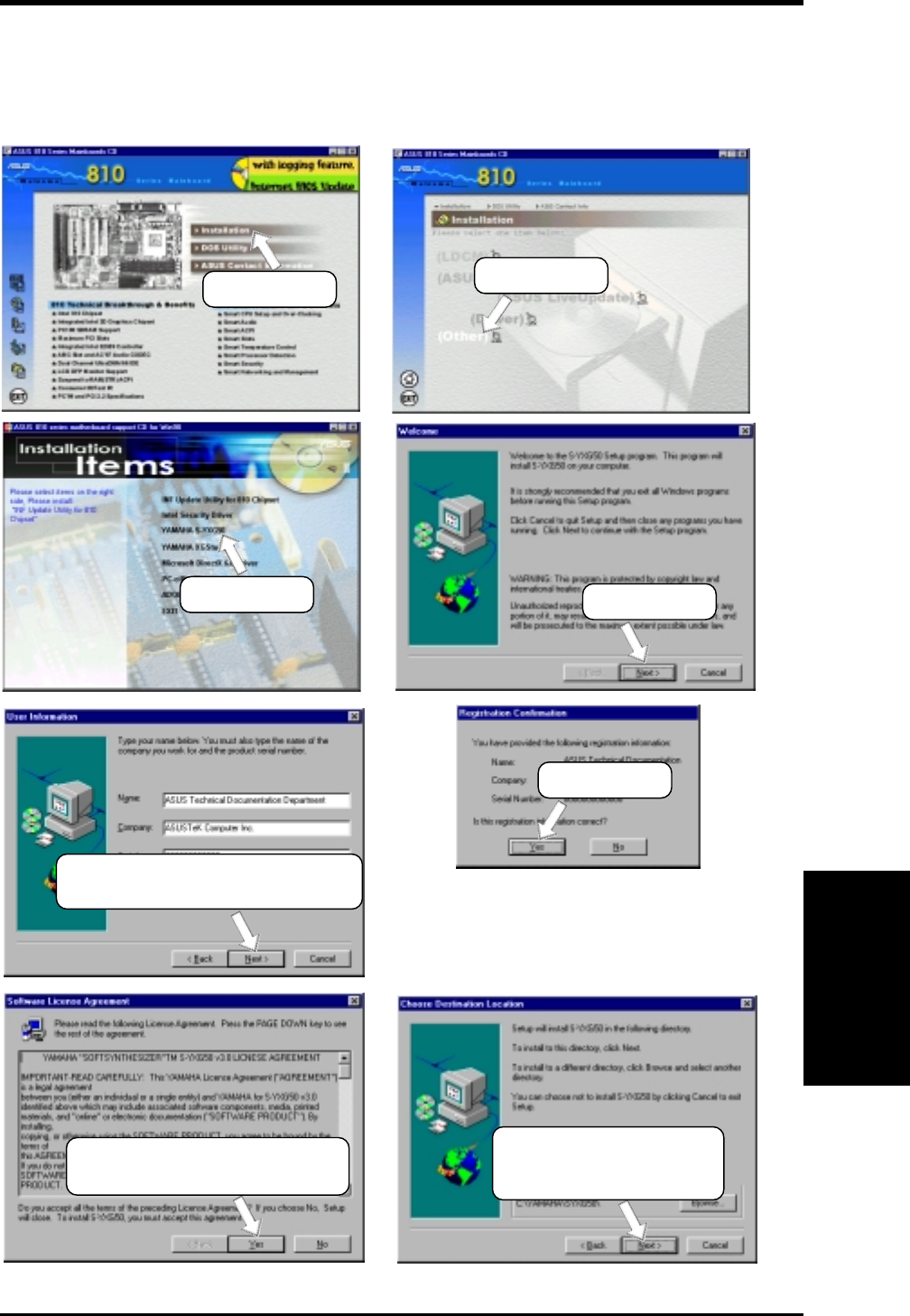
ASUS P3W User’s Manual 97
5. SOFTWARE SETUP
5. S/W SETUP
Windows 98
5.9.3 YAMAHA S-YXG50
Insert the Support CD that came with your motherboard into your CD-ROM drive
or double-click the CD drive icon in My Computer to bring up the setup screen.
(3) Click here.
(1) Click here. (2) Click here.
(4) Click here.
(5) Enter the information requested
and the click here
*
.
(6) Click here.
* The serial number can be found on the software license
agreement card.
(7) Click here only if you accept
the terms of the agreement.
(8) Click here and follow
the online instructions
to complete installation.
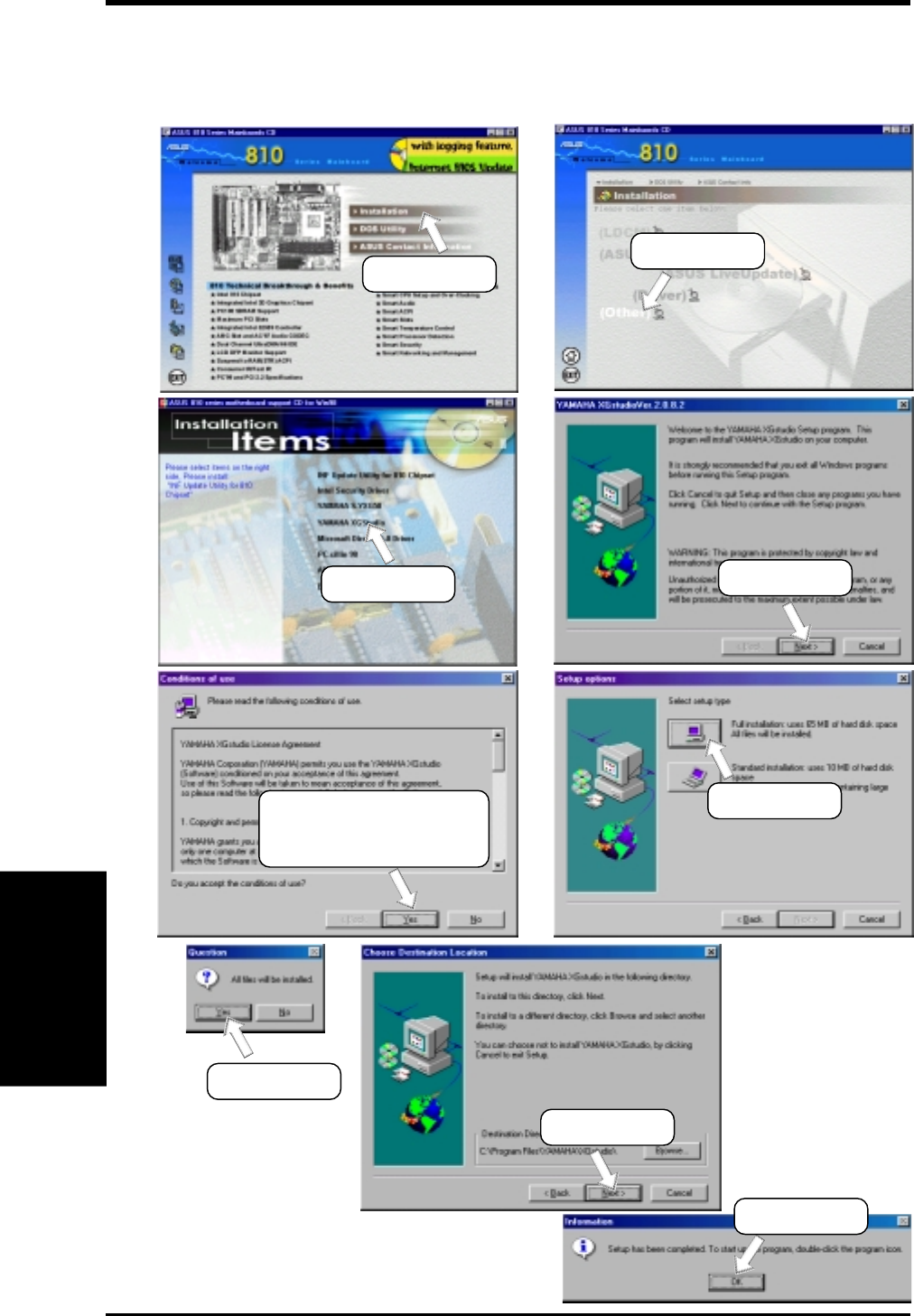
98 ASUS P3W User’s Manual
5. SOFTWARE SETUP
5. S/W SETUP
Windows 98
5.9.4 YAMAHA XGStudio
Insert the Support CD that came with your motherboard into your CD-ROM drive
or double-click the CD drive icon in My Computer to bring up the setup screen.
(1) Click here. (2) Click here.
(9) Click here.
(7) Click here.
(8) Click here.
(5) Click here only after
you have carefully read
the license agreement.
(6) Click here.
(3) Click here. (4) Click here.
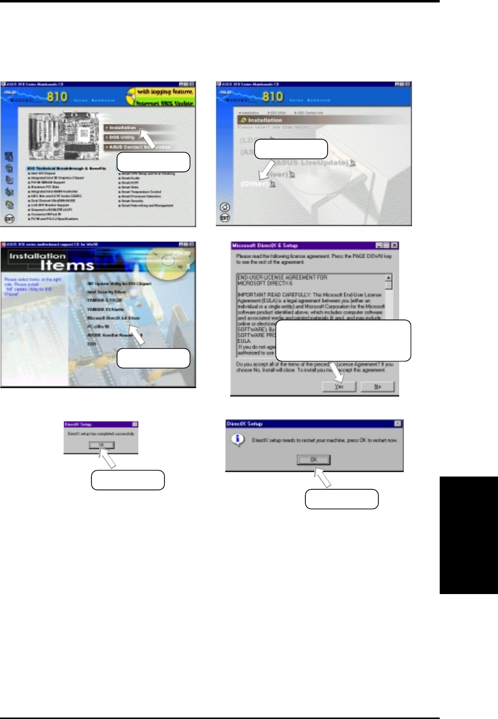
ASUS P3W User’s Manual 99
5. SOFTWARE SETUP
5. S/W SETUP
Windows 98
5.9.5 Microsoft DirectX 6.0 Driver
Insert the Support CD that came with your motherboard into your CD-ROM drive
or double-click the CD drive icon in My Computer to bring up the setup screen.
(1) Click here. (2) Click here.
(5) Click here.
(6) Click here.
(3) Click here.
(4) Click here only after you
have read the license
agreement.
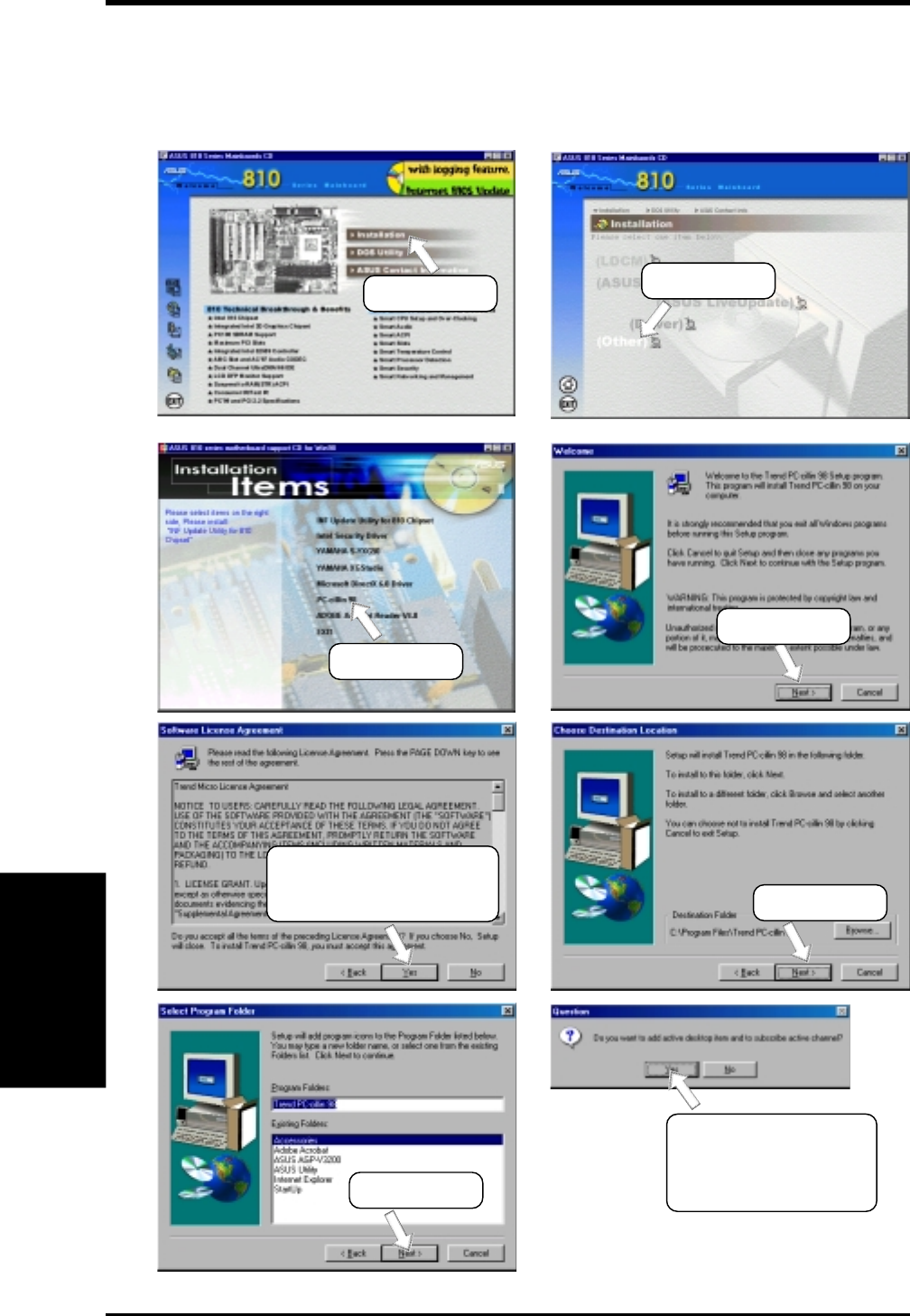
100 ASUS P3W User’s Manual
5. SOFTWARE SETUP
5. S/W SETUP
Windows 98
5.9.6 PC-cillin 98
Insert the Support CD that came with your motherboard into your CD-ROM drive
or double-click the CD drive icon in My Computer to bring up the setup screen.
(2) Click here.
(1) Click here.
(3) Click here.
(4) Click here.
(5) Click here only if you
accept the terms of the
license agreement. (6) Click here.
(7) Click here.
(8) Click here and then
follow the online
instructins to finish
installation.
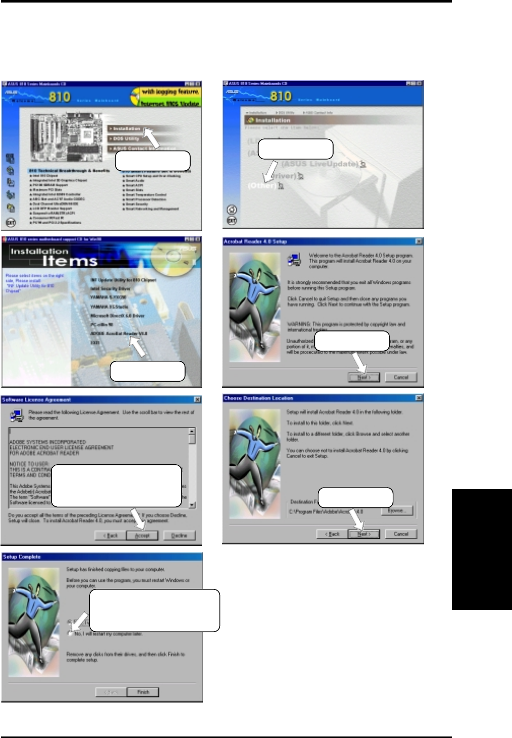
ASUS P3W User’s Manual 101
5. SOFTWARE SETUP
5. S/W SETUP
Windows 98
5.9.7 Adobe Acrobat Reader V4.0
Insert the Support CD that came with your motherboard into your CD-ROM drive
or double-click the CD drive icon in My Computer to bring up the setup screen.
(1) Click here. (2) Click here.
(3) Click here.
(4) Click here.
(5) Click here only if you
accept the terms of the
license agreement. (6) Click here.
(7) To install other drivers
or programs, click here
and then click Finish.
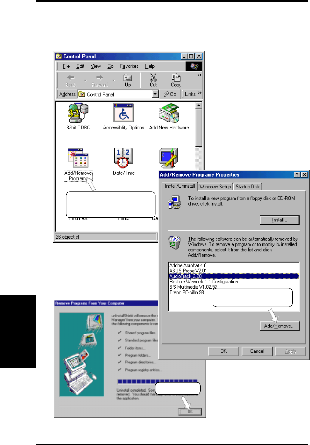
102 ASUS P3W User’s Manual
5. SOFTWARE SETUP
5. S/W SETUP
Windows 98
5.10 Uninstalling Programs
Add/Remove Programs is a basic component within Windows. You may use this
function if a program does not provide its own uninstall program.
(1) Double-click here to open
the Add/Remove Programs
Properties dialog box.
(2) Select the program to
remove and click here.
(3) Click here.
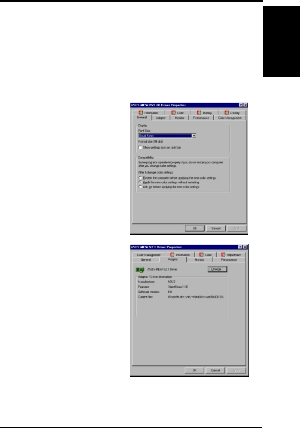
6. SOFTWARE REFERENCE
6. S/W REFERENCE
Windows 98
6.1 Display Properties
The motherboard’s built-in 2D/3D AGP VGA supports professional graphics de-
sign, gaming, learning, and business applications.
NOTE: Depending on your system configuration, components, and options, your
system may not show all of the settings displayed in the following pictures.
To open the Properties dialog box, right-click the desktop and select Properties, the
Settings tab, and then the Advanced button.
General
The Display box displays the current font size
of the selected monitor. To use a different font
size, click the arrow, and then click the font
size you want.
The Compatibility box allows you to specify
when to apply changes to system color set-
tings. NOTE: Some programs might not dis-
play colors correctly without being restarted
after you make changes. To avoid this prob-
lem, close the program, change the color set-
tings, and then open the program again.
Adapter
Shows what type of display adapter you are
currently using. To install the software for a
new display adapter, click Change.
ASUS P3W User’s Manual 103

ASUS P3W User’s Manual104
6. SOFTWARE REFERENCE
6. S/W REFERENCE
Windows 98
Monitor
Shows what type of monitor you are currently
using. To install the software for a new moni-
tor, click Change.
Performance
Specifies the degree of acceleration you want
for your graphics hardware. Full acceleration
is the fastest and is recommended for most
computers. If your ocmputer is having prob-
lems and you suspect graphics acceleration
to be the cause, use the highest setting at
which you do not have problems.
Color Management
Lists all the color profile currently associated
with your monitor. Click a profile to make it
the active profile. Otherwise, the default pro-
file is the active profile.
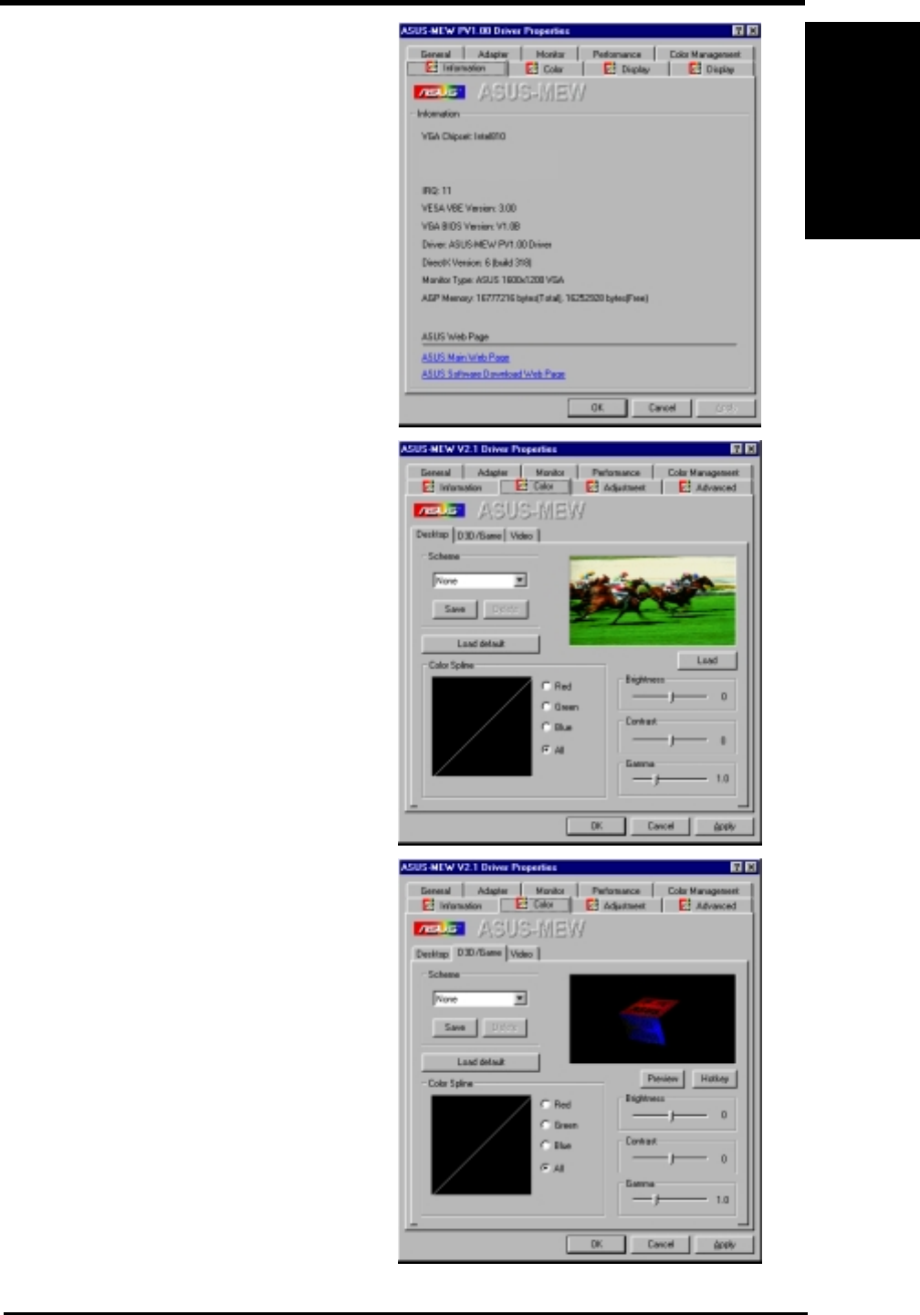
ASUS P3W User’s Manual 105
6. SOFTWARE REFERENCE
6. S/W REFERENCE
Windows 98
Information
Gives information on your graphics device
such as chipset, memory, BIOS, and drivers.
Internet links are also available for easy ac-
cess to the ASUS Web page for new updated
drivers and notices.
Color (Desktop)
Allows you to adjust the quality of your dis-
play according to your preference. Gamma
correction is available only in 16-bit color
and 24-bit color (true color, 16.7M-color)
modes. In 16-color and 8-bit color (standard
color, 256-color) modes, the gamma correc-
tion function is not supported.
Color (Direct3D/Game)
This is the same as the color adjustments for
the desktop but this applies to direct3D ap-
plications and games.
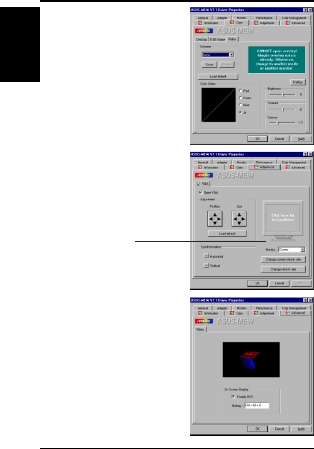
ASUS P3W User’s Manual106
6. SOFTWARE REFERENCE
6. S/W REFERENCE
Windows 98
Adjustment
Allows you to adjust the display position,
size, and refresh rate.
Change current refresh rate
Allows you to adjust the currently
displayed resolution refresh rate.
Change refresh rate
Allows you to adjust the de-
fault refresh rates for each
resolution and color settings.
Advanced
Allows you to assign hot keys to enable the
OnScreen Display (OSD). To use this func-
tion, select Enable OSD. You may want to
change the default hot key (CTRL+ALT+O)
if it conflicts with the hot keys of other games,
video players, or Windows programs.
Color (Video)
Lets you make color settings for videos.
ASUS P3W User’s Manual 107
6. SOFTWARE REFERENCE
6. S/W REFERENCE
Windows 98
6.2 ASUS PC Probe
ASUS PC Probe is a convenient utility to continuously monitor your com-
puter system’s vital components, such as fan rotations, Voltages, and tem-
peratures. It also has a utility that lets you review useful information about
your computer, such as hard disk space, memory usage, and CPU type, CPU
speed, and internal/external frequencies through the DMI Explorer.
6.2.1 Starting ASUS PC Probe
When ASUS PC Probe starts, a splash screen appears allowing you to select
whether or not to show the screen the next time you open PC Probe. To
bypass this startup screen, clear the Show up in next execution check box.
To open ASUS PC Probe, click the Windows Start button, point to Pro-
grams, and then ASUS Utility, and then click Probe Vx.xx.
The PC Probe icon will appear on the taskbar’s system tray indicating
that ASUS PC Probe is running. Clicking the icon will allow you to see the
status of your PC.
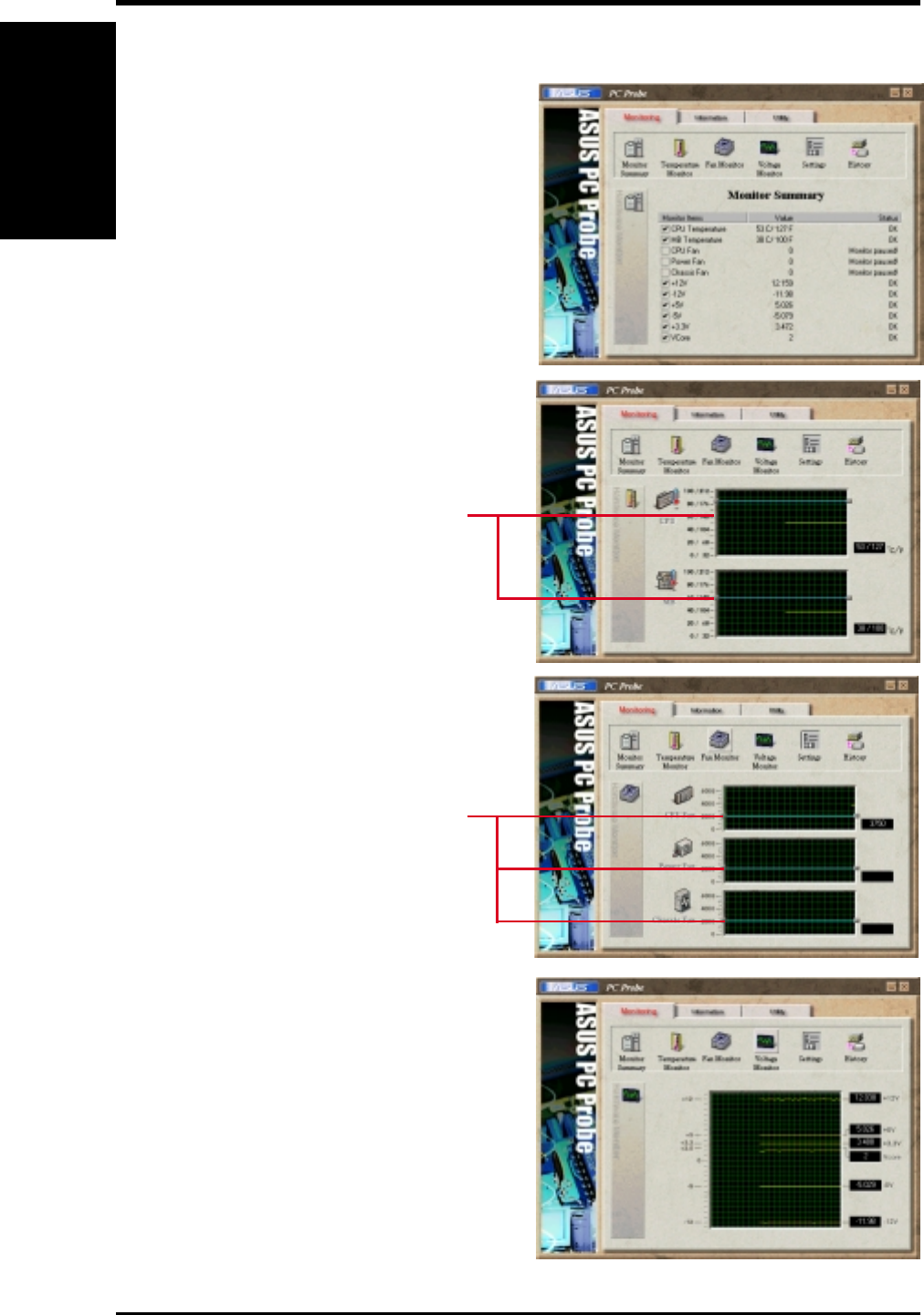
ASUS P3W User’s Manual108
6. SOFTWARE REFERENCE
6. S/W REFERENCE
Windows 98
6.2.2 Using ASUS PC Probe
Monitoring
Monitor Summary
Shows a summary of the items being
monitored.
Temperature Monitor
Shows the PC’s temperature.
Temperature Warning
threshold adjustment
(Move the slider up to increase the
threshold level or down to decrease
the threshold level)
Fan Monitor
Shows the PC’s fan rotation.
Voltage Monitor
Shows the PC’s voltages.
Fan Warning
threshold adjustment
(Move the slider up to increase the
threshold level or down to decrease
the threshold level)
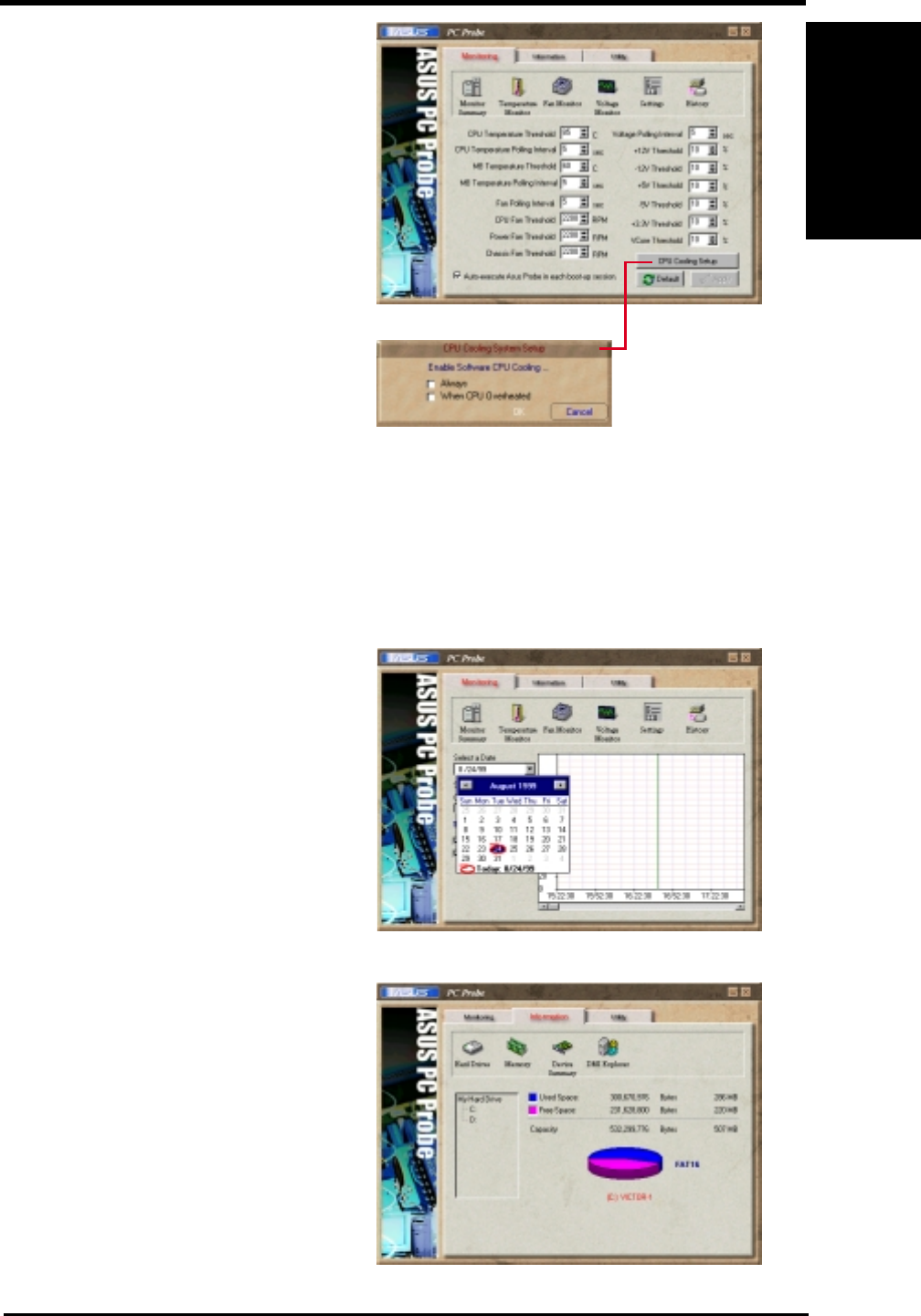
ASUS P3W User’s Manual 109
6. SOFTWARE REFERENCE
6. S/W REFERENCE
Windows 98
Information
Settings
Lets you set threshold levels and polling
intervals or refresh times of the PC’s tem-
perature, fan rotation, and voltages.
History
Lets you record the current monitoring
activity of a certain component of your
PC for future reference.
Hard Drives
Shows the used and free space of the PC’s
hard disk drives and the file allocation
table or file system used.
CPU Cooling System Setup
Lets you select when to enable software
CPU cooling. When When CPU Over-
heated is selected, the CPU cooling sys-
tem is enabled whenever the CPU tem-
perature reaches the threshold value.
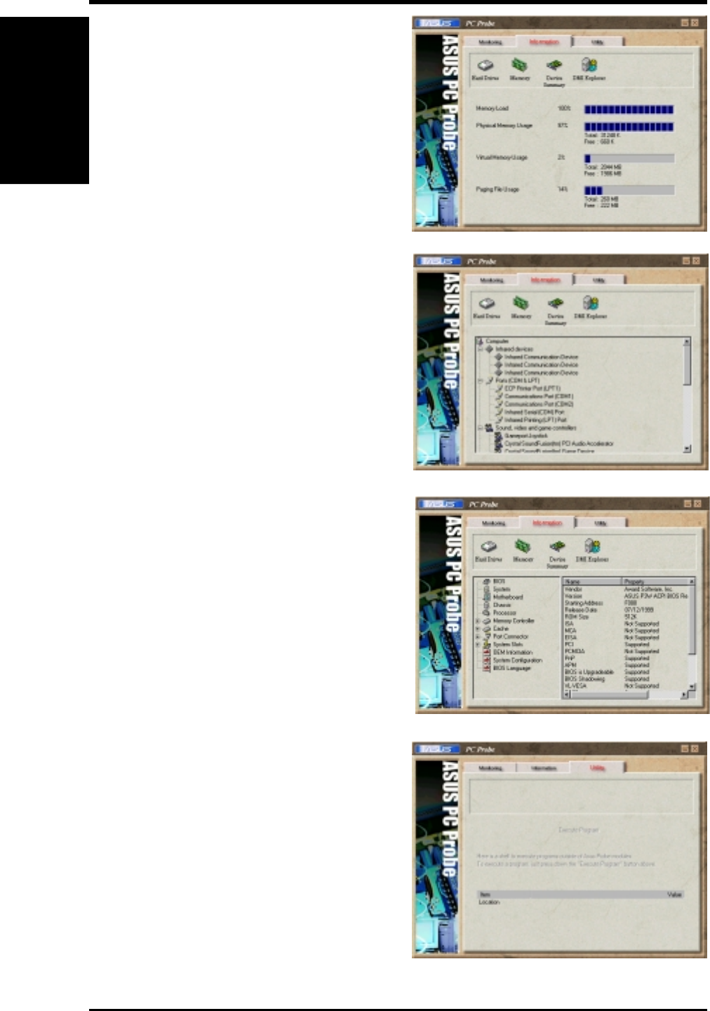
ASUS P3W User’s Manual110
6. SOFTWARE REFERENCE
6. S/W REFERENCE
Windows 98
Device Summary
Shows a summary of devices in your PC.
DMI Explorer
Shows information pertinent to the PC,
such as CPU type, CPU speed, and in-
ternal/external frequencies, and memory
size.
Utility
Lets you run programs outside of the
ASUS Probe modules. To run a program,
click Execute Program.
Memory
Shows the PC’s memory load, memory
usage, and paging file usage.
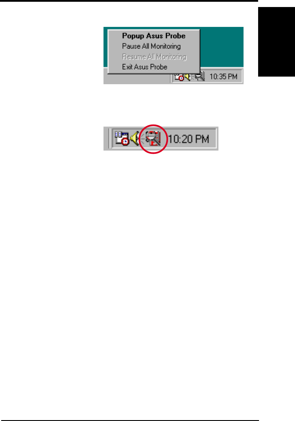
ASUS P3W User’s Manual 111
6. SOFTWARE REFERENCE
6. S/W REFERENCE
Windows 98
6.2.3 ASUS PC Probe Task Bar Icon
When the ASUS PC Probe senses
a problem with your PC, portions
of the ASUS PC Probe icon
changes to red, the PC speaker
beeps, and the ASUS PC Probe
monitor is displayed.
Right-clicking the PC Probe icon
will bring up a menu to open or
exit ASUS PC Probe and pause or
resume all system monitoring.
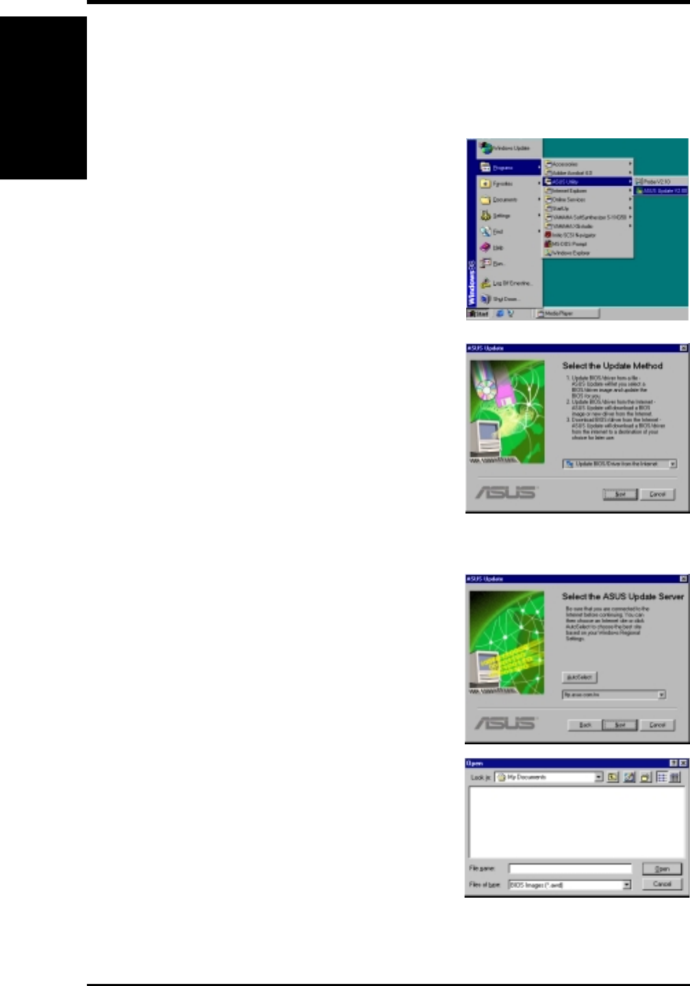
ASUS P3W User’s Manual112
6. SOFTWARE REFERENCE
6. S/W REFERENCE
Windows 98
6.3 ASUS LiveUpdate
ASUS LiveUpdate is a utility that allows you to update your motherboard’s
BIOS and drivers. The use of this utility requires that you are properly con-
nected to the Internet through an Internet Service Provider (ISP).
1. Start ASUS Update V2.00.
Launch the utility from Start | Programs | ASUS
Utility | ASUS LiveUpdate V1.00.
2. Select an update method.
3. If you selected updating/downloading from the
Internet, you will need to select an Internet site.
Choose the site that is closest to you or click
Auto Select.
If you selected Update from a file, you will
be prompted to locate the file.
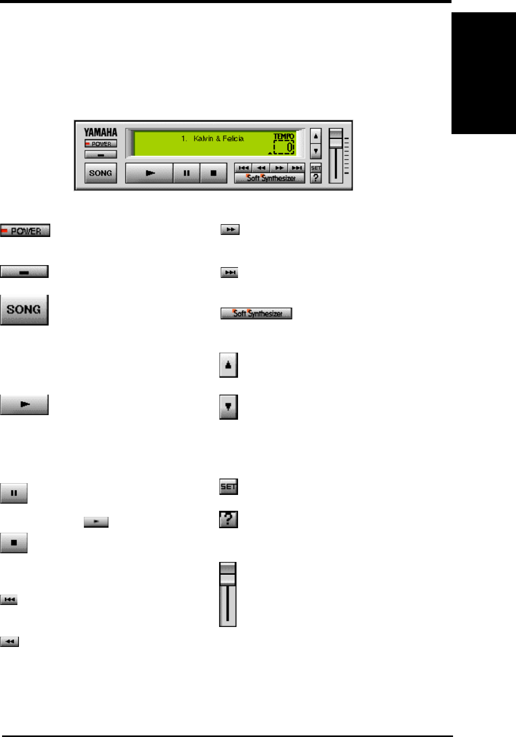
ASUS P3W User’s Manual 113
6. SOFTWARE REFERENCE
6. S/W REFERENCE
Windows 98
Closes the player. NOTE: You can also close
the player by pressing <Alt>+<F4>.
Minimizes the player to an icon.
Displays the Set Play List dialog box where
you can create a list of songs to play auto-
matically. NOTE: You can also display the
Set Play List dialog box by pressing
<Ctrl>+<O>.
Loads and plays the MIDO file currently se-
lected in Play List. When all the songs in the
Play List have finished, playing stops auto-
matically and the song at the beginning of
the list is designated as the current-play song.
Pauses the playing of a song. Click this but-
ton again or click to resume playing.
Stops the playing of a song and returns the
start-play location to the beginning of the
song.
Designates the first song in the Play List as
the new current-play song.
Designates the song just before the currently
playing song as the new current-play song.
6.4 Using Yamaha XGstudio Player
To start the Yamaha XGstudio, click Start, point to Programs, point to YAMAHA
XGstudio, and then click XGstudio Player.
6.4.1 Yamaha XGstudio Player Control Panel
Designates the song after the song currently
playing as the new current-play song.
Designates the last song in the Play List as
the new current-play song.
Displays the control panel for the Soft Syn-
thesizer features.
Speeds up the tempo of the song being played.
Slows down the tempo of the song being
played.
NOTE: The tempo is reset to 0 for each new
song.
Displays the Set Sound Source dialog box.
Displays Help. NOTE: You can also display
Help by pressing <F1>.
Increases/decreases the volume level of the
song being played by dragging the slider up/
down.
For detailed instructions and references to software and utilities, use the pro-
grams’ online help and electronic documentations.
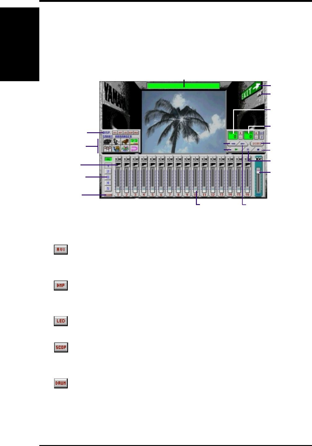
ASUS P3W User’s Manual114
6. SOFTWARE REFERENCE
6. S/W REFERENCE
Windows 98
Smart Arranger
Image Switcher
Assign Slider
Master
Volume
Slider
Exit
Song
Image Display Area
Minimize
Transpose Display
Panel
Tempo Display
Panel
Select Next
Select Previous
Play
Pause
Stop
Song Name Display Panel
Slider Function
Realtime Slider
Voice Select
6.5 Using Yamaha XGstudio Mixer
To start the Yamaha XGstudio, click Start, point to Programs, point to YAMAHA
XGstudio, and then click XGstudio Mixer.
6.5.1 Yamaha XGstudio Mixer Control Panel
Image Switcher
(AVI file): Video image
Displays the AVI file with the same name as the MIDI file being played. If
one is not available, the preset DEFAULT.AVI file is played.
(BMP file): Still image
Displays the BMP file with the same name as the MIDI file being played. If
one is not available, the preset DEFAULT.BMP file is played
(LED velocity meter): Animation
Displays the volume (amount of velocity) of each MIDI channel.
(SCOPE velocity meter): Animation
Displays the volume (amount of velocity) of each MIDI channel graphically
in a radio chart.
(drum and percussion): Animation
Displays animation with lights that match the drums and percussion used in
the drum channel (10ch).
Select Next
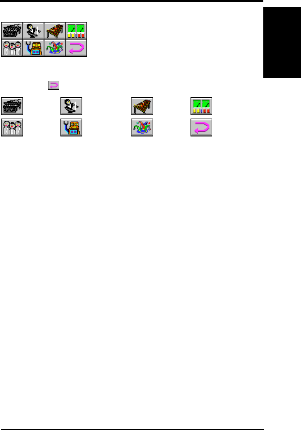
ASUS P3W User’s Manual 115
6. SOFTWARE REFERENCE
6. S/W REFERENCE
Windows 98
Smart Arranger
The Smart Arranger allows you to easily change the mood of a song. You can switch
between seven ensemble voice sets with these buttons. To return to the original
voice set, click .
Piano Orchestra Mallet Techno
Choir Robot Nature Return
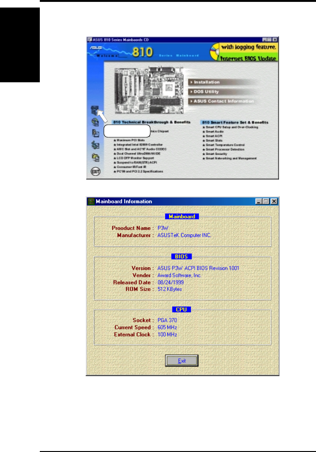
ASUS P3W User’s Manual116
6. SOFTWARE REFERENCE
6. S/W REFERENCE
Windows 98
6.6 Hardware Information
(1) Click here.
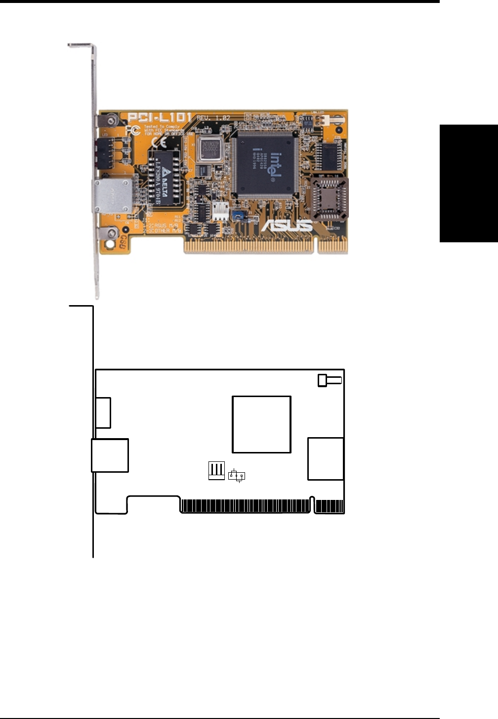
7. APPENDIX
7.1 PCI-L101 Fast Ethernet Card
LAN Activity
Output Signal
RJ45
LEDs
Motherboard type
Wake on LAN
Output Signal
ASUS
Other
Intel
Chipset
If you are using the ASUS PCI-L101 on an ASUS motherboard, leave the jumper on
its defaut setting of “ASUS.” If you are using another brand of motherboard, set the
jumper to “Other.” Connect the Wake on LAN (WOL) output signal to the
motherboard’s WOL_CON in order to utilize the wake on LAN feature of the moth-
erboard. Connect the LAN activity output signal (LAN_LED) to the system cabinet’s
front panel LAN_LED in order to display the LAN data activity.
7. APPENDIX
ASUS LAN Card
ASUS P3W User’s Manual 117

ASUS P3W User’s Manual118
7. APPENDIX
7.1.1 Features
•Intel 82558 Ethernet LAN Controller (Fully integrated 10BASE-T/100BASE-TX)
•Wake-On-LAN Remote Control Function Supported
•PCI Bus Master Complies to PCI Local Bus Rev. 2.1 specifications
•Consists of MAC & PHY (10/100Mbps) interfaces
•Complies to IEEE 802.3 10BASE-T and IEEE 802.3u 100BASE-TX interfaces
•Fully supports 10BASE-T & 100BASE-TX operations through a single RJ45 port
•Supports 32-bit Bus Master Technology / PCI Rev. 2.1
•Enhancements on ACPI & APM
•Adheres to PCI Bus Power Management Interface Rev. 1.0, ACPI Rev. 1.0, and
Device Class Power Management Rev. 1.0
•IEEE 802.3u auto-negotiation for 10Mbps/100Mbps Network Data Transfer
Rates.
•Provides LED indicators for monitoring network conditions
•Plug and Play
7.1.2 Software Driver Support
•NetWare ODI Drivers - Novell Netware 3.x, 4.x, DOS, OS/2 Client
•NDIS 2.01 Drivers - Microsoft LAN Manager, Microsoft Windows 3.11, IBM
LAN Server
•NDIS 3.0 Drivers - Microsoft Windows NT, Microsoft Windows 95, Microsoft
Windows 3.11
7.1.3 Question and Answer
Q: What is Wake-On-LAN ?
A: The Wake-On-LAN feature provides the capability to remotely power on sys-
tems supporting Wake-On-LAN by simply sending a wake-up frame. With this
feature, remotely uploading/downloading data to/from systems during off-peak
hours will be feasible.
Q: What can Wake-On-LAN do for you ?
A: Wake-On-LAN is a remote management tool with advantages that can reduce
system management workload, provide flexibility to the system administrator’s
job, and then of course save you time-consuming efforts and costs.
Q: What components does Wake-On-LAN require to be enable?
A: To enable Wake-On-LAN function, your system requires Ethernet LAN adapter
card that can activate Wake-On-LAN function, a client with Wake-On-LAN capa-
bility, and software such as LDCM Rev. 3.10 or up that can trigger wake-up frame.
7. APPENDIX
ASUS LAN Card
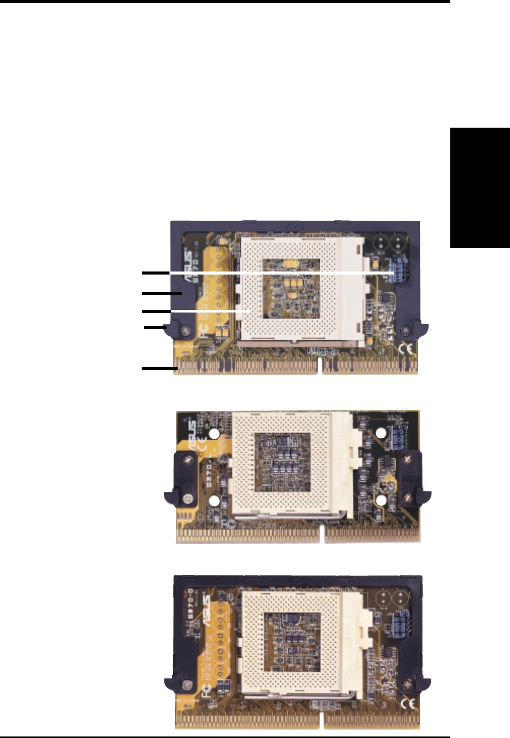
ASUS P3W User’s Manual 119
7. APPENDIX
7.2 S370 Series CPU Cards
The optional ASUS S370 Series CPU Cards allow Slot 1 motherboards to accept
socket 370 processors. The ASUS S370 Series CPU Cards give Slot 1 motherboard
owners an inexpensive way to upgrade their Pentium II computers using lower cost-
ing socket 370 processors. Since socket 370 processors are based on the Pentium II
design, the only difference is the connector and the amount of internal cache within
the processor.
The following are pictures of the ASUS S370 Series CPU Cards with black plastic
retainers attached to the edge. The retainer fins are used to hold the ASUS S370
Series CPU Cards in place using the motherboard’s Slot 1 retention mechanisms.
ASUS S370 CPU Card (standard model)
• Better Support with Full Retainer
• Low Cost
Slot 1 Compatible Connector
Socket 370
CPU Voltage Jumpers
Retainer Fin
Retainer
7. APPENDIX
S370 Series CPU Cards
ASUS S370-D CPU Card (performance model)
• Better Support with Full Retainer
• CPU Temperature Sensing
(on supported motherboards)
• Better Components
ASUS S370-L CPU Card (for smaller cases)
• Low Profile / Low Cost
• CPU Temperature Sensing
(on supported motherboards)
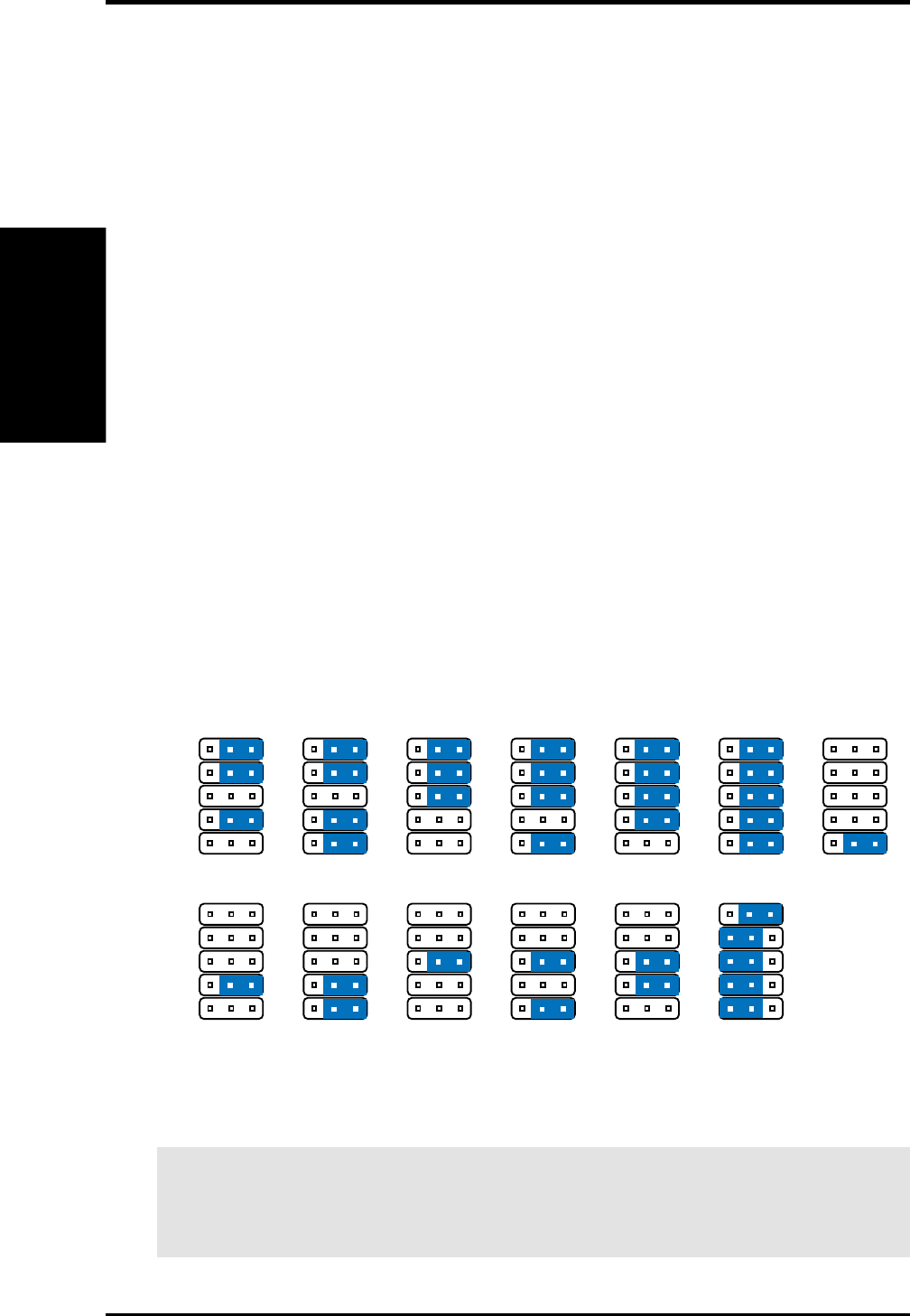
ASUS P3W User’s Manual120
7. APPENDIX
WARNING! Exceeding your socket 370 processor’s required voltage can dam-
age your processor permanently! Make sure that the jumpers are as shown for
“CPU Def.” unless otherwise specified before powering ON your motherboard.
7.2.1 Using the ASUS S370 Series CPU Card
The general procedure for using the ASUS S370 Series CPU Card is as follows:
1. Check the voltage setting for your socket 370 processor using the jumpers on
the card if necessary. For current socket 370 processors, the default setting should
be used. See the reverse side of the ASUS S370 Series CPU Card or this page
for voltage settings.
2. Install the socket 370 processor. Installation of socket 370 processors is exactly
like socket 7 processors. Lift the brown lever to 90° to install the processor and
lower the brown lever to lock the processor.
3. Insert the ASUS S370 Series CPU Card into Slot 1 on the motherboard. The
retainer fin on each side of the ASUS S370 Series CPU Card must catch on the
retention mechanism so that it locks in place.
4. Connect the socket 370 processor’s fan connector to the motherboard.
5. Make sure that no wires or objects come in contact with the fan.
7.2.2 S370 Series CPU Card Jumper Settings
The only set of jumpers on the ASUS S370 Series CPU Card is used for setting the
voltage sent to the CPU. Setting the CPU voltage is not necessary for current socket
370 processors. If required, your socket 370 processor should have its voltage re-
quirement printed on its surface or documentation. If no voltage is indicated or you
are not sure, use the “CPU Def.” setting as shown below.
Socket 370 CPU Voltage
1.80Volts
123
JP5
JP4
JP2
JP1
JP3
1.85Volts
123
JP5
JP4
JP2
JP1
JP3
1.90Volts
123
JP5
JP4
JP2
JP1
JP3
1.95Volts
123
JP5
JP4
JP2
JP1
JP3
2.05Volts
123
JP5
JP4
JP2
JP1
JP3
2.00Volts
123
JP5
JP4
JP2
JP1
JP3
2.10Volts
123
JP5
JP4
JP2
JP1
JP3
2.20Volts
123
JP5
JP4
JP2
JP1
JP3
2.30Volts
123
JP5
JP4
JP2
JP1
JP3
2.40Volts
123
JP5
JP4
JP2
JP1
JP3
2.50Volts
123
JP5
JP4
JP2
JP1
JP3
CPU Def.
123
JP5
JP4
JP2
JP1
JP3
2.60Volts
123
JP5
JP4
JP2
JP1
JP3
Reserved
123
JP5
JP4
JP2
JP1
JP3
7. APPENDIX
S370 Series CPU Cards

ASUS P3W User’s Manual 121
INDEX
Symbols
16-bit I/O Recovery Time 64
8-bit I/O Recovery Time 64
A
AC PWR Loss Restart 73
Adobe Acrobat Reader
Setup 101
AFLASH.EXE 48
ASUS LiveUpdate 92
Setup 92
Using 112
ASUS PC Probe
Setup 91
Using 107
ATAPI CD-ROM 76
ATX Power Supply Connector 46
ATX Power Switch Lead 45
Audio Port Connectors 37
Automatic Power Up 74
B
BIOS
Legend Bar 52
Managing 48
Menu Bar 52
Updating 48
BIOS Update 61
Boot Sequence 76
Boot Up Floppy Seek 77
Boot Up NumLock Status 77
Boot Virus Detection 77
C
Chassis Fan Connector 39
Chassis Fan Speed 75
CHS Capacity 57
Connectors
ATX Power Supply 46
Audio Port 37
Chassis Fan 39
Chassis Intrusion 44
Consumer IR 43
CPU Fan 39
Floppy Disk Drive 39
IDE Activity LED 38
IDE Activity LED Lead 38
Internal Audio 41
Internal Microphone 42
Internal Speaker 41
Joystick/MIDI 37
Monitor Output 37
Parallel Port 36
Power Fan 39
Power Supply Fan 39
Primary / Secondary IDE 38
Primary IDE 38
PS/2 Keyboard 35
PS/2 Mouse 35
Secondary IDE 38
Serial Port COM1 36
SMBus 42
Standard IR 43
System Warning Speaker 45
Thermal Sensor 46
Wake-On-LAN 40
Wake-On-Ring 40
CPU Bus Frequency (MHz) 60
CPU Core:Bus Freq. Multiple 60
CPU Fan Connector 39
CPU Fan Speed 75
CPU Latency Timer 63
CPU Level 1 Cache 61
CPU Level 2 Cache 61
CPU Level 2 Cache ECC Check 61
CPU Speed 60
CPU Temperature 75
CPU Vcore 61
CPU/SDRAM/PCI Freq. Ratio 60
Cylinders 56
D
D0000-DFFFF Shadow 70
Discard Changes 79
Display Cache CAS Latency 63
Display Cache Cycle Time 63
Display Cache Paging Mode 63
Display Cache RAS Precharge Time 63
Display Cache RAS to CAS Delay 63
Display Cache Window Size 63
DMA x Used By ISA 69

122 ASUS P3W User’s Manual
Driver Setup 93
Intel Security 95
Microsoft DirectX 98
E
ECP DMA Select 66
Exit Discarding Changes 78
Exit Saving Changes 78
Expansion Cards
Assigning IRQs 32
External Connectors 35
F
Floppy 3 Mode Support 54
Floppy Disk Access Control 65
Floppy Disk Drive Connector 39
Full Screen Logo 77
H
Halt On 59
Hardware Information 116
HDD Power Down 72
Head 57
Headers
Serial Port COM 2 43
High Priority PCI Mode 64
I
IDE Activity LED Lead 38
IDE Hard Drive 76
INF Update Utility for 810 Chipset
93, 94
Installation
Memory 25
Installed Memory 59
Intel Security Driver 95
Internal Audio Connectors 41
Internal Microphone Connector 42
Internal Speaker Connector 41
Interrupts
Request Table 33
Standard Assignments 32
IRQ XX Used By ISA 68
ISA Cards
Assigning DMA Channels 34
ISA MEM Block BASE 70
J
Joystick/MIDI Connector 37
K
Keyboard Lock Switch Lead 45
L
Language 58
LDCM Administrator Setup 88
LDCM Client Setup 86
Leads
ATX Power Switch 45
IDE Activity LED 38
Keyboard Lock Switch 45
Message LED 45
Reset Switch 45
System Management Interrupt 45
System Power LED 45
Legacy Diskette A 54
Legacy Diskette B 54
Legend Bar 52
LiveUpdate
Setup 92
Using 112
Load Setup Defaults 79
M
Managing and Updating Your BIOS 48
Maximum LBA Capacity 57
MB Temperature 75
Memory Hole At 15M-16M 64
Menu Bar 52
Message LED Lead 45
Microsoft DirectX
Driver Setup 98
Monitor Output Connector 37
Motherboard Layout 14
Motherboard Settings 17
Multi-Sector Transfers 57
INDEX

ASUS P3W User’s Manual 123
O
ONB VGA BIOS First 68
Onboard AC97 Modem Controller 65
Onboard CIR I/O 66
Onboard CIR IRQ 66
Onboard FDC Swap A & B 65
Onboard Game Port 66
Onboard ISA Bridge 64
Onboard MIDI I/O 66
Onboard MIDI IRQ 66
Onboard Parallel Port 66
Onboard PCI IDE Enable 64
Onboard Serial Port 1 65
Onboard Serial Port 2 65
Onboard VGA 63
Operating Systems 84
OS/2 Onboard Memory > 64M 61
Other Boot Device Select 76
P
Panel Connector
ATX Power Switch Lead 45
Keyboard Lock Switch Lead 45
Message LED Lead 45
Reset Switch Lead 45
System Management Interrupt Lead
45
System Power LED Lead 45
System Warning Speaker Connector
45
Parallel Port Connector 36
Parallel Port Mode 66
Part Locations 13
Password
Supervisor 58
User 58
PC Probe
Setup 91
Using 107
PC-cillin 98 Setup 99
PCI 2.1 Support 64
PCI Latency Timer 67
PCI/VGA Palette Snoop 67
PIO Mode 57
Plug & Play O/S 77
INDEX
Power Connection Procedures 47
Power Management 71
Power Supply Fan Connector 39
Power Supply Fan Speed 75
Primary IDE Connector 38
Procedure
Hardware Setup 17
Procedures
Power Connection 47
Programs
Uninstalling 100
PS/2 Keyboard Connector 35
PS/2 Mouse Connector 35
PS/2 Mouse Function Control 61
PWR Button < 4 Secs 72
PWR Up On Modem Act 73
Q
Quick Power On Self Test 77
R
Removable Device 76
Reset Switch Lead 45
S
Save Changes 79
SDRAM Address Setup Time 63
SDRAM CAS Latency 62
SDRAM Configuration 62
SDRAM Cycle Time (Tras, Trc) 63
SDRAM Page Closing Policy 63
SDRAM RAS Precharge Time 63
SDRAM RAS to CAS Delay 62
Secondary IDE Connector 38
Sector 57
Serial Port COM 2 Header 43
Serial Port COM1 Connector 36
Settings
Automatic Timeout Reboot 20
CPU External Frequency 22
I/O Voltage 21
JumperFree™ Mode 18
Motherboard 17
Onboard Audio 19
Safe Mode 20

124 ASUS P3W User’s Manual
INDEX
Slot 1/5 IRQ 67
Slot 2 IRQ 67
Slot 3/6 IRQ 67
Slot 4 IRQ 67
SMART Monitoring 57
SMBus Connector 42
Software Setup
Adobe Acrobat Reader 101
LDCM Administrator 88
LDCM Client 86
LiveUpdate 92
PC Probe 91
PC-cillin 98 99
Yamaha S-YXG50 96
Yamaha XGStudio 96
Supervisor Password 58
Support CD
Main Menu 81
Navigation Button 81
Submenus 82
Suspend Mode 72
Suspend-to-RAM Capability 72
SYMBIOS SCSI BIOS 67
System Date 54
System Management Interrupt Lead 45
System Memory 24
System Power LED Lead 45
System Time 54
System Warning Speaker Connector 45
T
Thermal Sensor Connector 46
Translation Method 56
Type 55
U
UART2 Use Standard Infrared 66
Ultra DMA Mode 57
Uninstalling Programs 100
Universal Serial Bus Ports 36
Updating BIOS
Procedures 49
USB Function 68
USB Legacy Support 61
User Password 58
Using
LiveUpdate 112
PC Probe 107
Yamaha XGstudio Mixer 114
Yamaha XGstudio Player 113
V
Video Off Method 72
Video Off Option 72
Video ROM BIOS Shadow 70
Voltage
+12V 75
+3.3V 75
+5V 75
-12V 75
-5V 75
VCORE 75
W
Wake On LAN 73
Wake On PS2 KB/Mouse 74
Wake-On-LAN Connector 40
Wake-On-Ring Connector 40
Y
Yamaha S-YXG50 96
Yamaha XGStudio 96
Yamaha XGstudio Mixer 114
Yamaha XGstudio Player 113

®
Goes Mobile!Goes Mobile!
Goes Mobile!Goes Mobile!
Goes Mobile!
F7400 Series
Professional Notebook PC
14.1” TFT Color Display
300/333/366/400+MHz
Built-in DVD/MPEG2 Decoder
L7300/7200 Series
All-in-One Compact Notebook PC
13.3” or 12.1” TFT Color Display
300/333/366/400+MHz
M8300/8200 Series
Thin & Light Convertible Notebook PC
13.3” or 12.1” TFT Color Display
233/266/300/333/366/400+MHz

®
Ultra-Fast CD-ROM
Drive Interface Type: ATAPI/Enhanced IDE supporting PIO mode 4, multi-
word DMA mode 2, UltraDMA/33
Disc Formats: Audio CD, CD-ROM (mode 1 & mode 2), Mixed
mode, CD-ROM/XA (mode 2, form 1 & form 2),
Video CD, CD-I, Photo CD (single & multi-session),
Karaoke CD, CD Extra, I-Trax, CD-R, CD-RW
Disk Size: 8 cm and 12 cm
OS Compatibility: DOS 6.xx, Windows 3.x/95/98, OS/2 Warp, Netware,
SCO UNIX
Cache Buffer Size: 128KB
Data Transfer Rate: CD-S500 7500 KBps maximum
CD-S450 6750 KBps maximum
CD-S400 6000 KBps maximum
Access Time: 75ms
•Supports high speed CD-Audio playback
•Supports high speed digital audio extraction
•Supports UltraDMA/33 transfer mode
•Compatible with all CD formats
•Supports multi-read function (CD-R/CD-RW)

®
Barebone Servers
Pentium
®
III PC100 ECC Ultra2 SCSI 5.25”
Pentium
®
II Max. Memory Onboard Fixed Storage Hot-Swap Trays
Support (GB) (Channels) Devices
AP100 1113 0
AP200 2113 0
AP2000 2 1 1 4 3 or 5*
AP2500 2 1 1 4 3 or 5*
AP3000 2 Xeon™2 2 4 3 or 5*
AP6000 2 1 1 4 8**
AP7500 2 1 1 4 8**
AP8000 2 Xeon™2 2 4 8**
Mid-Range Servers
AP6000
AP7500
AP8000
Rack Mountable
Value Servers
AP2000
AP2500
AP3000
Group Servers
AP100
AP200
* Three 1.6-inch or five 1-inch SCA-2 SCSI hard drives
** Eight 1.6-inch or 1-inch SCSI hard drives
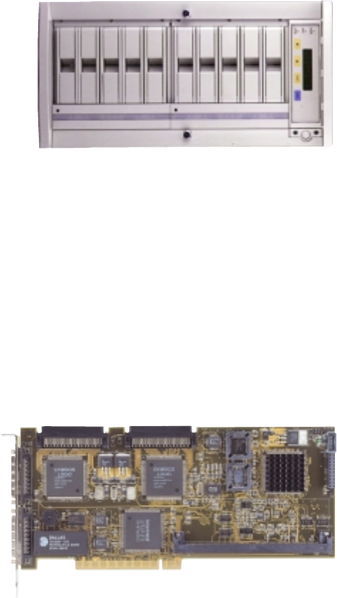
ASUS AR1000 RAID Sub-system
with DA3000 SCSI-to-SCSI RAID Controller
•Supports 5x86 RAID processor and two 72-pin SIMM sockets for up to 128MB
cache memory
•Supports three Ultra2 SCSI channels; up to 80MB/sec data transfer rate
•Supports multiple Host/Drive channel capacity
•Redundant controller capacity
•Supports non-RAID, RAID levels 0, 1, 0+1, 3, 5
•On-line failure drive rebuilding
•Automatic rebuilding — supports local/global spare drive
•On-line expansion capacity
•Supports SAF-TE (SCSI Accessed Fault-Tolerant Enclosure) feature
•Provides LCD panel and RS-232 port to configure RAID
•Ten 1.0” or six 1.6” Ultra2 SCSI SCA-2 hot-swappable drive bays
•19” rack mountable (height: 5U)
•LED for hard disk power and
working status
•Two 8cm system fans and four 6cm
drive fans
•Aluminum disk arrays for easy
heat dissipation
•350W redundant power supply
ASUS PCI-DA2100/2200 Series SCSI RAID Card
•PCI-DA2100 series support 4x86 DX4-100 processor
•PCI-DA2200 series support 5x86-133 processor
•One 72-pin SIMM socket supports up to 128MB cache memory
•RAID levels 0, 0+1, 3, 5, non-RAID
•PCI-DA2100A supports Ultra Wide SCSI interface and dual channels
•PCI-DA2200A supports Ultra2 SCSI interface and single channel
•PCI-DA2200B supports Ultra2 SCSI interface and dual channels
•Automatic bad sector reassignment
•Supports both global and lo-
cal spare drive operation
•Background rebuilding
•PCI rev. 2.1 compliant
•Up to 8 logical drives and 8
partitions per logical drive;
number of drives for each
logical drive has no limitation
