Asus Ls99 Users Manual
LS99 e660_ls99
e660_ls99 e660_ls99
e660_ls99 e660_ls99
LS99 to the manual 4f21ad29-b534-44ac-a205-44a0dcaf5716
2015-01-21
: Asus Asus-Ls99-Users-Manual-237694 asus-ls99-users-manual-237694 asus pdf
Open the PDF directly: View PDF ![]() .
.
Page Count: 34
Chapter 1 Introduction 1
1. Introduction
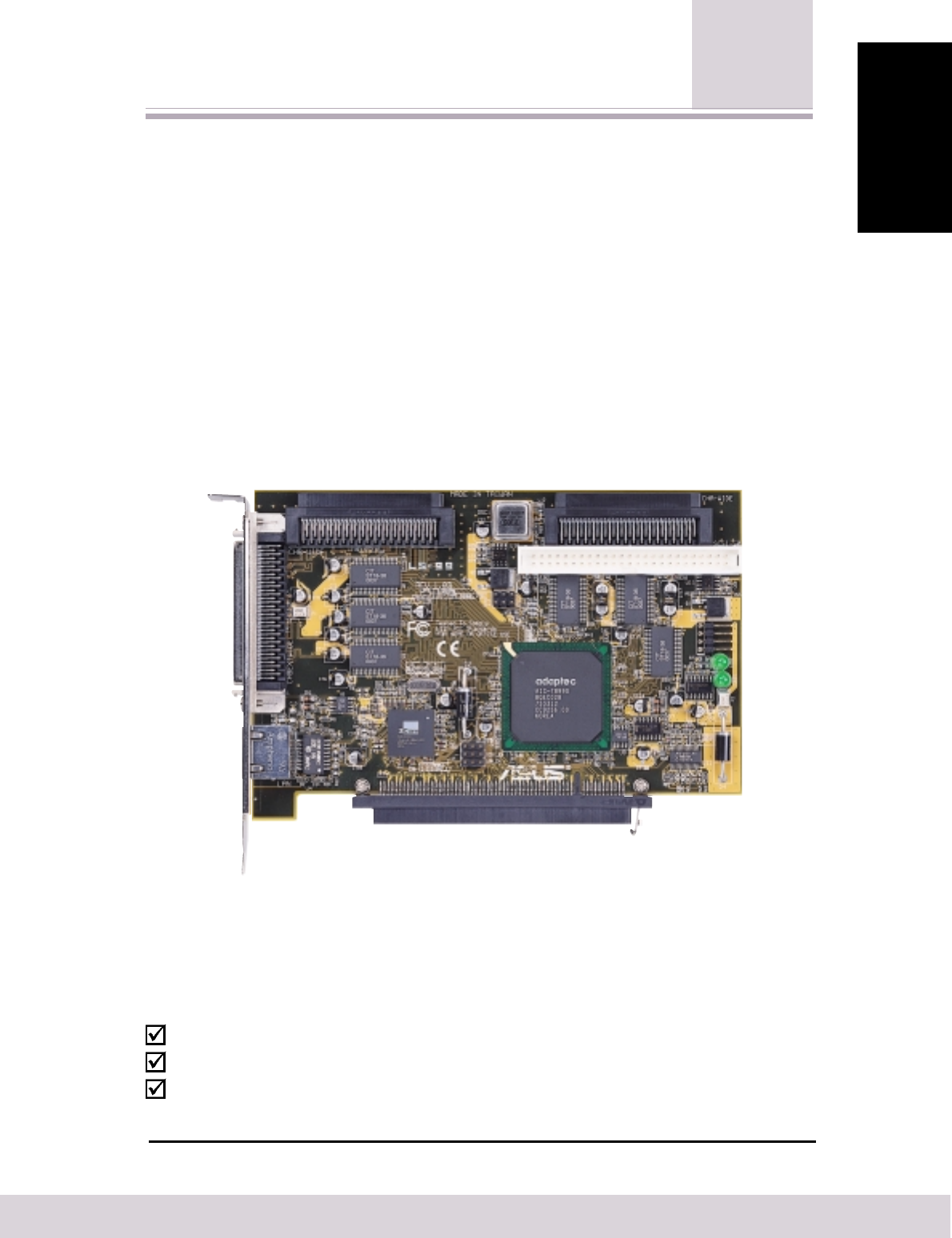
The ASUS LS99 LAN/SCSI card can only be installed on a motherboard with an
ASUS proprietary expansion slot. See 2.3 Installing the ASUS LAN/SCSI card for
location of this slot.
The ASUS LS99 LAN/SCSI card enables you to connect up to 30 SCSI devices—
such as very large arrays of high-performance HDDs, external storage subsystems,
clustered configurations, Ultra160 hard disk drives, scanners, and CD-ROM drives.
There is also an optional integrated 3Com 3C920 Fast Ethernet controller for
connecting your PC to a network.
Ultra160 is a new generation of SCSI technology that increases SCSI performance
from 80 MBytes/sec to 160 MBytes/sec. In addition to providing much greater
performance, Ultra160 SCSI enables a maximum allowable cable length of 12 meters
for optimal connectivity and flexibility.
1
1
Introduction
1
When only one Ultra2 or Ultra160 SCSI device is connected, the cable length can be up to 25 meters (82 feet).
1.1 Package Contents
Check that your package is complete. If you discover damaged or missing items,
contact your retailer.
(1) ASUS LAN/SCSI card
(1) 68-pin internal LVD SCSI cable with terminator
(1) 50-pin internal SE narrow SCSI cable
2Chapter 1 Introduction
1. Introduction
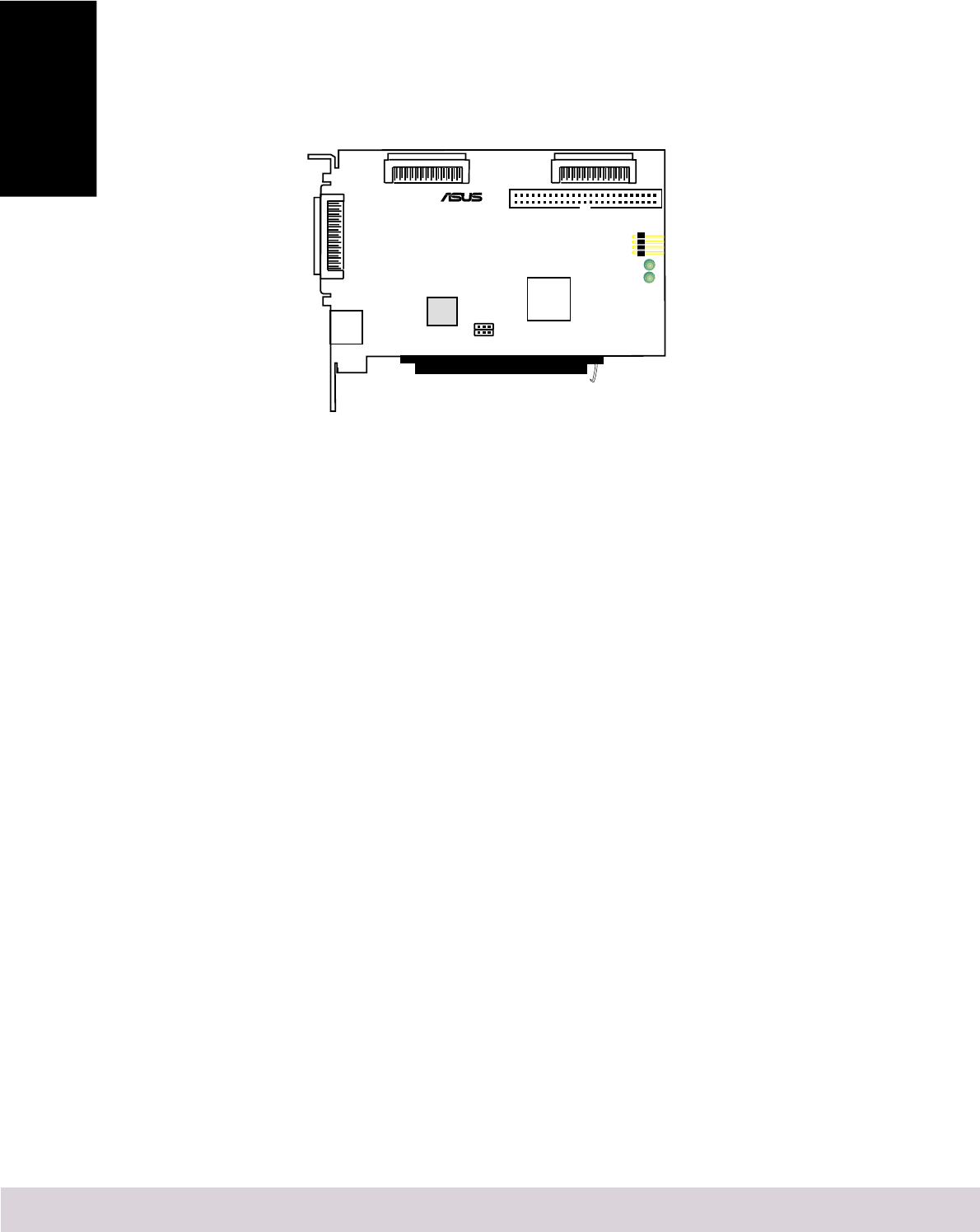
1.2 Product Features
The ASUS LS99 LAN/SCSI card has two independent SCSI channels, each with a
maximum throughput of 160 MBytes/sec. SCSI Channel A has two internal
connectors (CHA-WIDE and SCSI-50). SCSI Channel B has one internal connector
(CHB-WIDE) and one external connector (CHBEXTWIDE).
®
Internal Narrow
SCSI Connector
(Channel A)
1
Internal Ultra160
SCSI Connector
(Channel B)
Internal Ultra160
SCSI Connector
(Channel A)
SCSI_EN
LAN_EN
LED2
LED1
CHA-WIDE
CHB-WIDE
3Com
LAN
Controller
Adaptec
AIC-7899G
SCSI
Controller
RJ45
Connector
External Ultra160
SCSI Connector
(Channel B)
SCSI-50
CHBEXTWIDE
SCSILED
ASUSCONNECT Latch
1.2.1 PCI Interface
•Full 32-bit (33 MHz) DMA bus master
•Zero wait-state bus master data bursts
•PCI 5V bus support
1.2.2 SCSI Interface
•Two separate SCSI channels
•16-bit SE/LVD
•One 68-pin external high-density SCSI interface for channel B
•One 68-pin internal high-density SCSI interface for each channel A & B
•One 50-pin fast-SCSI connector for channel A
•Fast, Ultra, and Ultra2 data transfer capability
•SCSI Plug and Play
•SCSI activity LED for each channel
1.2.3 Network Interface
•3Com EtherLink 10/100 LAN controller
•32-bit PCI host interface
•One RJ45 LAN connector
•Remote system alert and network keepalive support
1.2.4 LAN/SCSI card Characteristics
•Dimensions: Approximately 6.0 x 4.0 inches (15cm x 10cm)
•ASUS proprietary 32-bit PCI card edge connector
Chapter 2 Hardware Installation 3
2. HW Installation
Discharge any static electricity build-up before handling your LAN/SCSI card by
touching a grounded metal object (like the exposed metal parts on the back of your
computer). Remove the ASUS LS99 Dual Channel LAN/SCSI card from the pack-
ing and check that it is not damaged.
CAUTION: Static charges on your body can damage electronic com-
ponents. Handle plug-in boards by the edge; do not touch board com-
ponents or gold connector contacts. The use of a static ground strap is
recommended.
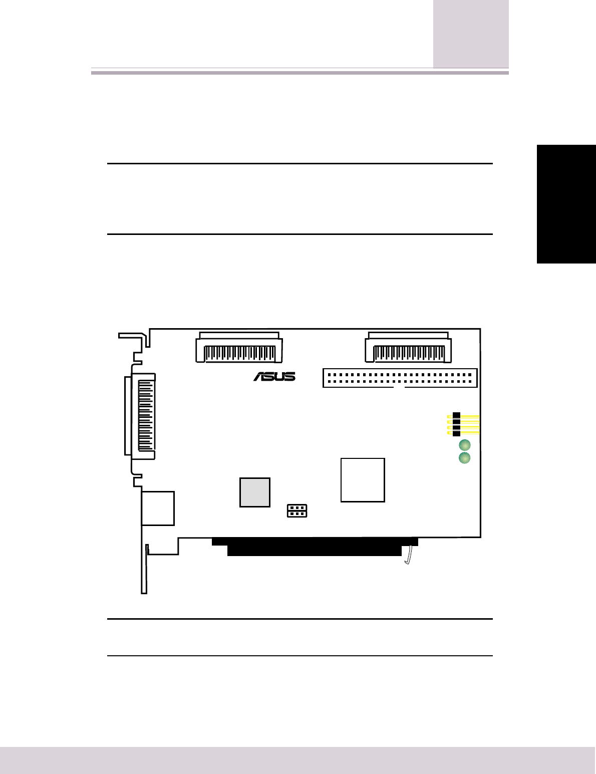
2.1 ASUS LS99 LAN/SCSI card Layout
®
Internal Narrow
SCSI Connector
(Channel A)
1
Internal Ultra160
SCSI Connector
(Channel B)
Internal Ultra160
SCSI Connector
(Channel A)
SCSI_EN
LAN_EN
LED2
LED1
CHA-WIDE
CHB-WIDE
3Com
LAN
Controller
Adaptec
AIC-7899G
SCSI
Controller
RJ45
Connector
External Ultra160
SCSI Connector
(Channel B)
SCSI-50
CHBEXTWIDE
SCSILED
ASUSCONNECT Latch
NOTE: Grayed components are available only on certain models at
the time of purchase.
2
Hardware Installation

4Chapter 2 Hardware Installation
2. HW Installattion
2.2 LAN/SCSI card Settings
1) SCSI Controller Setting (SCSI_EN)
This jumper allows you to enable/disable the SCSI controller function. The default
setting is Enable.
SCSI Controller Setting
123 123
Disable
Enable
SCSI_EN
SCSI_EN
LAN_EN
®
LAN_EN
2) LAN Controller Setting (LAN_EN) (only on model with LAN controller)
This jumper allows you to enable/disable the LAN controller function. The default
setting is Enable.
LAN Controller Setting
123 123
Disable
Enable
LAN_EN
LAN_EN
SCSI_EN
®
SCSI_EN

Chapter 2 Hardware Installation 5
2. HW Installation
2.3 Installing the ASUS LAN/SCSI card
1. Locate the ASUS proprietary expansion
slot.
2. Remove the expansion slot cover on the
back of the computer aligned with the
ASUS proprietary expansion slot. Save
the slot cover screw.
3. Carefully insert the
ASUSCONNECT edge
connection of the ASUS
LS99 LAN/SCSI card
into this slot. Make sure
the edge connector is
properly engaged before
pressing the card into
place.
4. Press down firmly until
the latch clicks into
place. The latch on the LAN/SCSI card should secure the card into place.
5. The bracket around the CHBEXTWIDE connector should fit where you removed
the expansion slot cover. Secure it with the slot cover screw before making the
internal and external SCSI bus connections.
2.4 Removing the ASUS LAN/SCSI card
Release the latch by inserting a rigid tip between the latch and the connector and
pushing the latch outward away from the connector.
ASUS Proprietary Expansion Slot
PCI Expansion Slot
®
Internal Narrow
SCSI Connector
(Channel A)
1
JP3
JP4
SCSI_EN
LAN_EN
LED2
LED1
CHA-WIDE
CHB-WIDE
3Com
LAN
Controller
Adaptec
AIC-7899G
SCSI
Controller
RJ45
Connector
External Ultra160
SCSI Connector
(Channel B)
SCSI-50
CHBEXTWIDE
SCSILED
ASUSCONNECT
Latch
To release latch

6Chapter 2 Hardware Installation
2. HW Installattion
2.5 Setting Up SCSI Devices
There are several things to do before you connect your SCSI devices to the ASUS
LS99 LAN/SCSI card:
•Check the SCSI IDs
•Set the termination
•Connect the power cables
Since setup can vary from device to device, always refer to the device’s documentation
for specific instructions.
Below are some guidelines for setting SCSI IDs and termination on your devices.
Refer to the Appendix for more information on these topics.
2.5.1 Check the SCSI IDs
The ASUS LS99 LAN/SCSI card and each device you connect to it must have a
unique SCSI ID number ranging from 0 to 15 on each channel. The peripheral device
SCSI IDs are usually set with jumpers or with a switch on the peripheral. Refer to
the peripheral manufacturer’s instructions and to the user’s manual for your computer
to determine the ID of each device and how to change it. No two devices on the
same SCSI channel can have the same SCSI ID.
The ASUS LS99 LAN/SCSI card is preset to ID 7 for each channel and should not
be changed. If you boot from a SCSI hard disk, make sure the hard disk SCSI ID is
set to 0. (Most SCSI hard disks are preset to SCSI ID 0 at the factory.) The SCSI IDs
for internal devices are usually set with jumpers; SCSI IDs for external devices are
usually set with a switch on the back of the device.

Chapter 2 Hardware Installation 7
2. HW Installation
Determine the SCSI ID of each device on the SCSI bus. Note any duplications. Make
any necessary changes to the SCSI IDs and record the IDs for future reference. The
following table is provided as a place to keep this record.
2.5.2 SCSI ID Record
SCSI ID SCSI Device Channel A SCSI Device Channel B
15
14
13
12
11
10
09
08
07
06
05
04
03
02
01
00
2.5.3 Terminate the Ends
To ensure reliable communication on the SCSI bus, the device at the end of each
cable, or the end of the cable itself, must have a terminator installed (or enabled).
Terminators must be removed, or termination must be disabled, on devices between
the ends of each cable.
NOTE: When connecting Ultra160 or Ultra2 SCSI devices, the SCSI
bus must be terminated either on the end of the cable (with a permanent
terminator) or with a separate terminating connector. Ultra SCSI and
earlier single-ended devices can terminate the bus directly from the
device. If you use an Ultra SCSI terminator on an LVD Ultra160 and
Ultra2 SCSI bus you will force the bus to Single-ended mode, limiting
the speed and cable distance. For this reason be sure that you have the
necessary Ultra160 or Ultra2 cable or terminator before installing the
Ultra160 SCSI devices.
8Chapter 2 Hardware Installation
2. HW Installattion
2.6 Connecting Devices
You can connect a total of 30 SCSI devices to the ASUS LS99 LAN/SCSI card, with
up to 15 devices on each SCSI channel. Before connecting devices, be sure to review
2.5 Setting Up SCSI Devices.
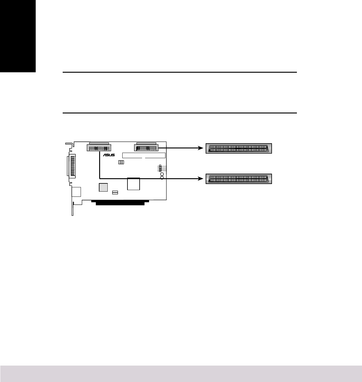
2.6.1 Connecting Internal Ultra160 and Ultra2 Devices
A special 68-pin LVD cable is provided to connect internal Ultra160 or Ultra2 SCSI
devices. If your cables are not marked, you can identify most LVD cables as having
twisted pairs of the flat ribbon cable between the device connectors.
The ASUS LS99 LAN/SCSI card has two separate Ultra160 SCSI channels, as shown
in 2.1 ASUS LS99 LAN/SCSI card Layout. Each channel has an internal LVD/SE
connector to which you can connect internal SCSI devices. Follow these steps to
connect your internal Ultra160 and Ultra2 devices.
NOTE: We recommend that Ultra160 and Ultra2 SCSI devices are
kept on a separate SCSI channel from Ultra SCSI devices. This allows
the newer Ultra160 and Ultra2 SCSI devices to transfer data at their
maximum speed.
Internal Ultra160 and Ultra2 SCSI Connectors
Internal Ultra160
1
35
34
68
CHA-WIDE
Internal Ultra160
1
35
34
68
CHB-WIDE
®
1. Locate the provided 68-pin internal LVD SCSI cable, which has the twisted
wires.
2. Plug the non-terminated end of the cable(s) to the internal LVD/SE connector(s).
Pin-1 must match on all connections.

Chapter 2 Hardware Installation 9
2. HW Installation
3. Plug additional internal Ultra160 and Ultra2 SCSI devices to the other cable
connectors, starting with the connector at the terminated end of the cable. Make
sure to match pin-1 on all connections.
NOTE: Internal Ultra160 and Ultra2 SCSI devices come from the
factory with termination disabled and cannot be changed. Proper
termination is provided by the terminator at the end of the LVD SCSI
cable.
4. Connect a power cable from your computer’s internal power supply to each
internal SCSI device.
5. Most PC cabinets are designed with a front panel LED, which may already be
connected to an existing IDE controller. You may connect this LED cable to
your SCSI host adapter. This connection causes the front panel LED to indicate
activity on the SCSI bus.
2.6.2 Connecting Internal Wide SCSI Devices
You can connect Wide SCSI devices to the internal LVD/SE connectors. If you do
this, we recommend that you connect them to the SCSI channel A LVD/SE connector
and that you connect all Ultra160 and Ultra2 devices to the SCSI Channel B connector.
Follow these steps to connect Wide SCSI devices:
1. Connect one end of a 68-pin internal Wide SCSI cable to the Channel A internal
68-pin connector on the ASUS LS99 LAN/SCSI card.
2. Connect the other end of the cable to a terminated Ultra/Fast Wide SCSI device.
Pin-1 must match on all connections.
3. If you have other Ultra/Fast Wide SCSI devices, attach them to the connectors
between the two ends of the cable. Be sure these other devices are unterminated.
4. Connect a power cable from your computer’s internal power supply to each
internal SCSI device.
10 Chapter 2 Hardware Installation
2. HW Installattion
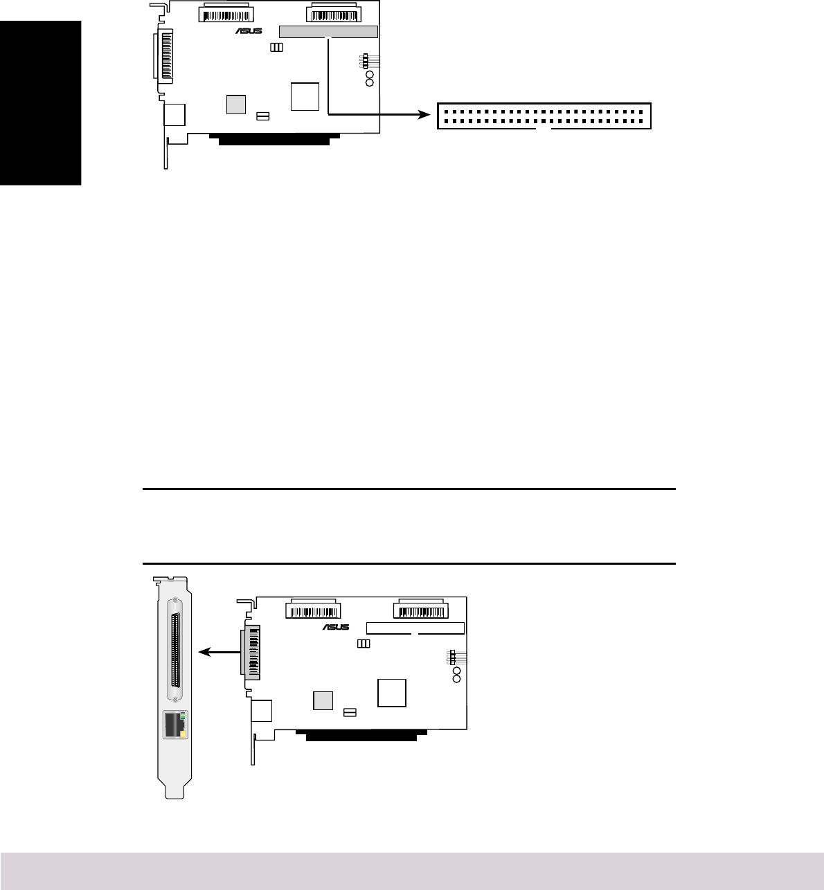
2.6.3 Connecting Ultra/Fast Narrow SCSI Devices
If you have internal Ultra/Fast Narrow SCSI devices with standard 50-pin connectors,
you can connect them to the 50-pin internal SE Narrow SCSI connector. Follow
these steps to connect the devices:
1. Locate the provided 50-pin internal Ultra/Fast Narrow SCSI cable.
2. Connect one end of the cable to the 50-pin internal SE Narrow SCSI connector.
Internal Narrow SCSI Connector
1
SCSI-50
Internal Narrow
®
3. Connect the other end of the cable to a terminated Ultra/Fast Narrow SCSI device.
Pin-1 must match on all connections.
4. If you have other Ultra/Fast Narrow SCSI devices, attach them to the connectors
between the two ends of the cable. Be sure these other devices are unterminated.
5. Connect a power cable from your computer’s internal power supply to each
internal SCSI device.
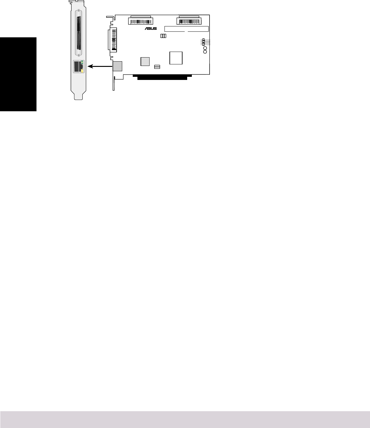
2.6.4 Connecting External SCSI Devices
You can connect external Ultra160 and Ultra2 SCSI devices to the 68-pin external
LVD/SE SCSI connector. The external devices will require a 68-pin VHDCI external
LVD SCSI cable.
NOTE: We recommend that you connect only Ultra160 and Ultra2
SCSI devices to the external SCSI connectors in order to achieve the
maximum data transfer rate.
External SCSI Connector
®

Chapter 2 Hardware Installation 11
2. HW Installation
Follow these steps to connect external SCSI devices:
1. Connect one end of the external SCSI cable to the external Ultra160 connector.
2. Connect the other end of the cable to a SCSI connector on the back of an external
device. Pin-1 must match on all connections. If you are installing only one external
device, terminate the device and skip to step 4.
3. Connect the other external SCSI devices by linking each device to the previous
one. Terminate only the device at the end of the chain.
4. Connect power cables to all external SCSI devices and to the computer.
2.6.5 More Information About Termination
The last SCSI device on the end of each SCSI bus cable must be terminated, and
termination must be disabled for all other devices in the middle of the cables. Ultra160
and Ultra2 SCSI devices are automatically unterminated, but Ultra SCSI and Fast/
Wide SCSI devices do have termination that you must check. For more information,
refer to the Appendix.
If you are using external Ultra2 or Ultra160 devices, be sure to use an LVD terminator
to terminate the last device in the chain. If you use a single-ended, active terminator
(sometimes called an Ultra terminator) the SCSI devices will not operate at their
maximum speed.
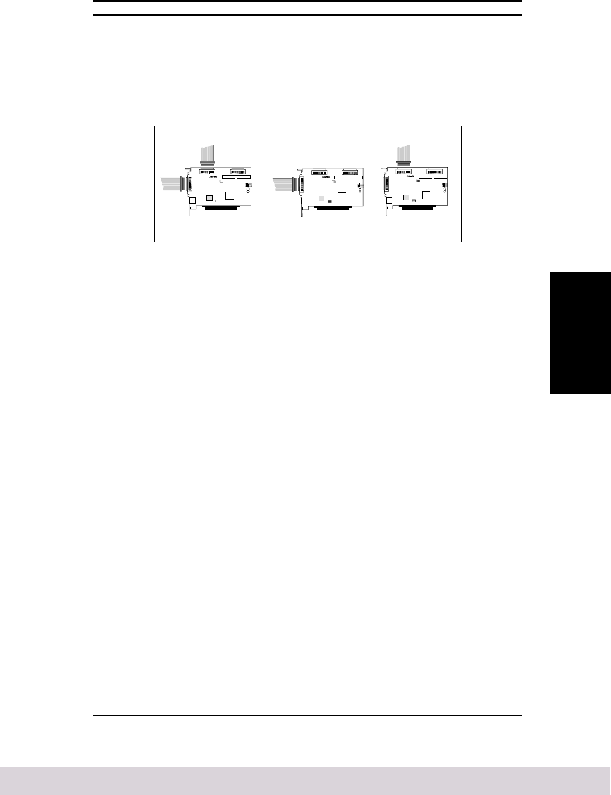
2.6.6 Connecting the LED Connector
Most computers have an LED disk activity light on the front panel of the system
case. If you choose to disconnect the cable from the LED connector on the
motherboard and connect it to the LED connector on the LAN/SCSI card as shown
in the diagram below, the LED on the front panel of the computer will light whenever
there is activity on the SCSI bus.
NOTE: If you connect the LED cable to the LAN/SCSI card,the LED
disk activity light will no longer indicate disk activity on the non-
SCSI disk drives.
®
SCSI Activity LED Connector
LED
GND
GND
LED2
LED1
(Channel B)
(Channel A)
12 Chapter 2 Hardware Installation
2. HW Installattion
2.6.7 Connecting to the Network
A connector is available (only on model with LAN) to allow connection to a Local
Area Network (LAN) through a network hub.
Fast Ethernet Port Connector (RJ45)
®
Chapter 3 Configuring the ASUS LS99 13
3. Configuration
3
Configuring the
ASUS LS99
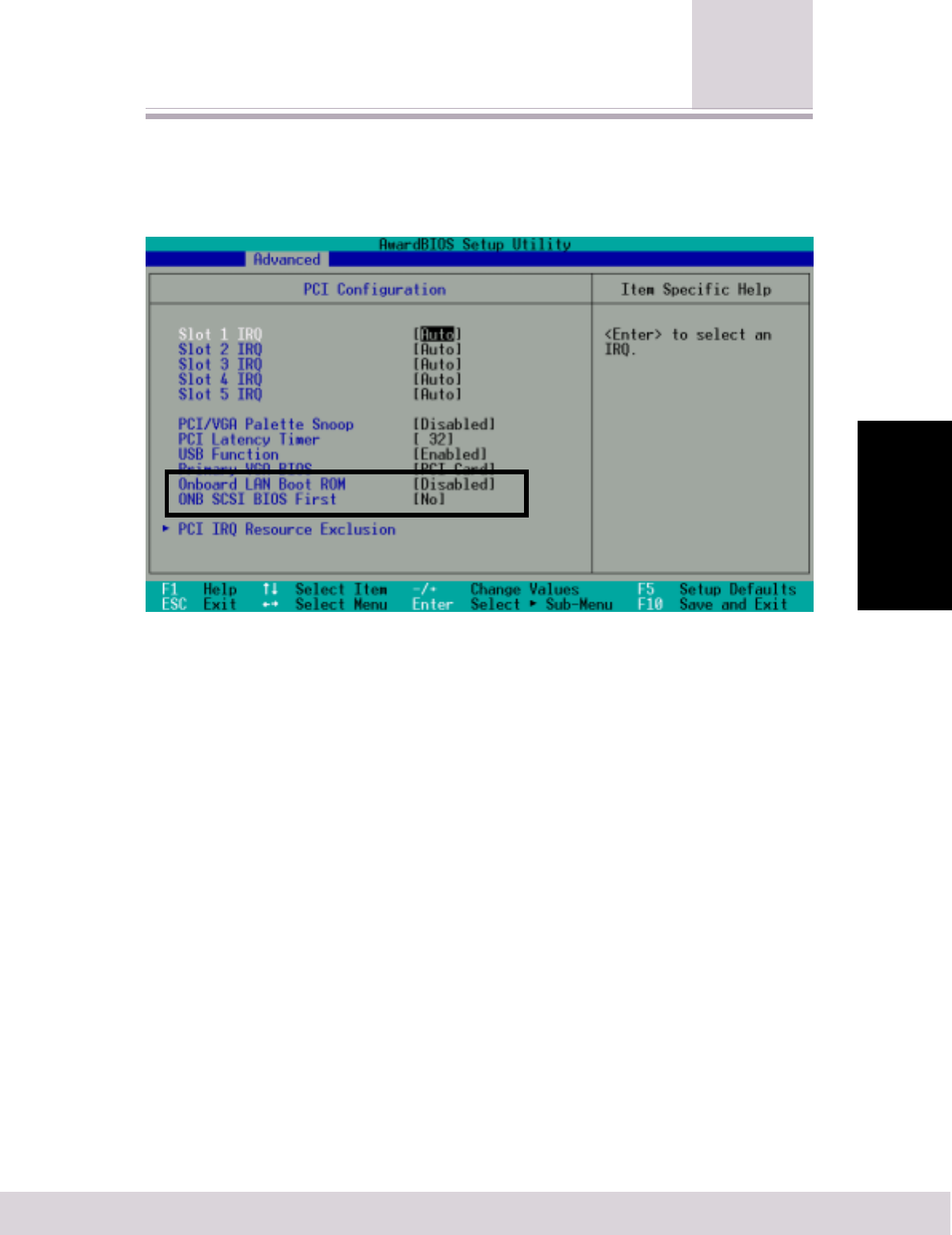
3.1 Configuring the Motherboard BIOS
To access the motherboard BIOS setup program, press <Delete> during POST.
Onboard LAN Boot ROM [Disabled]
Leave on default setting. Configuration options: [Disabled] [Enabled]
ONB SCSI BIOS First [No]
Setting this field to [Yes] gives priority to the onboard SCSI BIOS for SCSI functions
over other SCSI controllers. The default setting is [NO]. Configuration options: [Yes]
[No]
This screen image is for reference purposes only. Refer to your motherboard BIOS for actual settings.

14 Chapter 3 Configuring the ASUS LS99
3. Configuration
3.2 Configuring Using SCSI
Select
SCSISelect, which is included with the ASUS LS99 SCSI Card, enables you to change
SCSI settings without opening the computer or handling the card. SCSISelect also
enables you to low-level format or verify the disk media of your SCSI hard disk
drives. The following table lists the available and default settings for each SCSISelect
option. The settings marked as “Auto-sync” are automatically synchronized for both
SCSI channels—for example, if you change the Boot Channel option to B First on
Channel A, the change will apply to Channel B as well. All other options can be set
separately for each of the two SCSI channels.
The default settings are appropriate for most systems and should not be changed.
Run SCSISelect if you need to change or view current settings, or if you need to use
the SCSI disk utilities.
Chapter 3 Configuring the ASUS LS99 15
3. Configuration
SCSI
Select
Options Available Settings Default Setting
SCSI Bus Interface Definitions
SCSI Controller ID 0-15 7
SCSI Controller Parity Enabled Disabled
Disabled
SCSI Controller Termination: Ch. A
1
Enabled Enabled
Disabled
Ch. B Enabled Enabled
Disabled
Y Type Connection
(Termination Disabled)
®®
Normal Connection
(Termination Enabled)
®
OR
Additional Options
Boot Device Configuration
Boot SCSI Controller AIC-7899 A at slot 00 02:0D:00 AIC-7899 A at slot 00 02:0D:00
AIC-7899 B at slot 00 02:0D:01
Boot SCSI ID 0-15 0
Boot LUN Number
2
0-7 0
SCSI Device Configuration
Sync Transfer Rate (MBytes/sec) 160, 80.0, 53.4, 40.0, 160
32.0, 26.8, 20.0,
16.0, 13.4, 10.0,
ASYN
Initiate Wide Negotiation Yes, No Yes (Enabled)
Enable Disconnection Yes, No Yes (Enabled)
Send Start Unit Command Yes, No Yes (Enabled)
BIOS Multiple LUN Support
3
Yes, No No (Disabled)
Include in BIOS Scan
3
Yes, No Yes ( Enabled)
Advance Configuration
Reset SCSI Bus at IC Initialization Enabled, Disabled Enabled
Display <Ctrl> <A> Messages During Enabled, Disabled Enabled
BIOS Initialization [Auto-sync]
Extended Int 13 Translation for Enabled, Disabled Enabled
DOS Drives > 1 GByte
POST Display Mode [Auto-sync] Verbose, Silent, Diagnostic Verbose
SCSI Controller Int 13 Support Enabled, Disabled:NOT scan, Enabled
Disabled:scan bus
Domain Validation
3
[Auto-sync] Enabled, Disabled Enabled
Support Removable Disks Under Int 13 Disabled, Disabled
as Fixed Disks
3
Boot Only,
All Disks
BIOS Support for Bootable CD-ROM
3
Enabled, Disabled Enabled
Boot Channel [Auto-sync] A First, B First A First
Boot SCSI ID [Auto-sync] 0-15 0
Boot LUN Number
2
[Auto-sync] 0-7 0
1
Leave this on its default setting.
2
Setting is valid only if Multiple LUN Support is enabled.
3
Settings are valid only if host adapter BIOS is enabled.

16 Chapter 3 Configuring the ASUS LS99
3. Configuration
3.2.1 Starting SCSI
Select
Follow these steps to start SCSISelect:
1. Turn on or restart your computer.
During the startup process, pay careful attention to the messages that appear on
your screen.
2. When the following message appears on your screen, press the <Ctrl>+<A>
keys simultaneously (this message appears for only a few seconds):
Press <Ctrl><A> for SCSISelect (TM) Utility!
3. Select SCSI Channel A or B. Most SCSISelect options can be set separately for
each SCSI channel.
4. From the menu that appears, use the arrow keys to move the cursor to the option
you want, then press <Enter>.
NOTE: If you have difficulty viewing the display, press <F5> to toggle
between color and monochrome modes. (This feature may not work
on some monitors.)
3.2.2 Exiting SCSI
Select
Follow these steps to exit SCSISelect:
1. Press <Esc> until a message prompts you to exit (if you changed any settings,
you are prompted to save the changes before you exit).
2. At the prompt, select Yes to exit, then press any key to reboot the computer. Any
changes you made in SCSISelect take effect after the computer boots.
3.2.3 Using SCSI
Select
Settings
To select an option, use the arrow keys to move the cursor to the option, then press
<Enter>. In some cases, selecting an option displays another menu. You can return
to the previous menu at any time by pressing <Esc>.
To restore the original SCSISelect default values, press <F6> from the main
SCSISelect screen.
SCSI Bus Interface Definitions
•SCSI Controller ID—(Default: 7) Sets the SCSI ID for the SCSI card. The ASUS
LS99 SCSI card is set to 7,which gives it the highest priority on the SCSI bus.
We recommend that you do not change this setting.
•SCSI Controller Parity (Default: Enabled) When set to Enabled, verifies the
accuracy of data transfer on the SCSI bus. Leave this setting enabled unless any
SCSI device connected to the ASUS LS99 SCSI card does not support SCSI
parity.
•SCSI Controller Termination (Default: Enabled) Determines the termination
setting for the SCSI card. The default setting is Enabled.

Chapter 3 Configuring the ASUS LS99 17
3. Configuration
Advanced Options
Boot Device Configuration
•Boot SCSI Controller—(Default: A First) Specifies which of the two SCSI
channels the boot device is connected to (if the computer boots from a SCSI
device). If you change this setting, the change automatically applies to both
SCSI channels.
•Boot SCSI ID—(Default: 0) Specifies the SCSI ID of your boot device. We
recommend that you do not change the default setting. If you change this setting,
the change automatically applies to both SCSI channels.
•Boot LUN Number—(Default: 0) Specifies which LUN (Logical Unit Number)
to boot from on your boot device. This setting is not valid unless Multiple LUN
Support is enabled (see Advanced Configuration on the next page). If you change
this setting, the change automatically applies to both SCSI channels.
SCSI Device Configuration
SCSI Device Configuration options can be set individually for each connected SCSI
device.
NOTE: To configure settings for a SCSI device, you must know its
SCSI ID (see 3.2.4 Using SCSI Disk Utilities).
•Sync Transfer Rate—(Default: 160) Determines the maximum synchronous data
transfer rate that the SCSI card supports. We recommend that you leave the
maximum (default) value of 160 MBytes/sec.
•Initiate Wide Negotiation—(Default: Yes ) When set toYes, the SCSI card attempts
16-bit data transfer (wide negotiation). When set to No, the SCSI card uses 8-bit
data transfer unless the SCSI device requests wide negotiation.
NOTE: Set Initiate Wide Negotiation to No if you are using an 8-bit
SCSI device that hangs or shows other performance problems with
16-bit data transfer rate enabled.
•Enable Disconnection—(Default: Yes) When set toYes, allows the SCSI device
to disconnect from the SCSI bus. Leave the setting on Yes if two or more SCSI
devices are connected to the SCSI card. If only one SCSI device is connected,
changing the setting to No results in slightly better performance.
•Send Start Unit Command—(Default: Yes) When set to Yes, sends the Start Unit
Command to the SCSI device at bootup.

18 Chapter 3 Configuring the ASUS LS99
3. Configuration
The following options have no effect if the SCSI Card BIOS is disabled. (The SCSI
Card BIOS is normally enabled by default.)
•BIOS Multiple LUN Support—(Default: No) Leave this setting on No if the
device does not have multiple Logical Unit Numbers (LUNs). When set to Yes,
the SCSI card BIOS provides boot support for a SCSI device with multiple LUNs
(for example, a CD “jukebox” device in which multiple CDs can be accessed
simultaneously).
•Include in BIOS Scan—(Default: Yes )When set to Yes, the SCSI card BIOS
includes the device as part of its BIOS scan at bootup.
Advanced Configuration
NOTE: Do not change the Advanced Configuration options unless
absolutely necessary.
•Reset SCSI Bus at IC Initialization—(Default: Enabled) When set to Enabled,
the SCSI card generates a SCSI bus reset during its power-on initialization and
after a hard reset.
•Display <Ctrl> <A> Messages during BIOS Initialization— (Default: Enabled)
When set to Enabled, the SCSI card BIOS displays the “Press <Ctrl> <A> for
SCSISelect (TM) Utility!” message on your screen during system bootup. If this
setting is disabled, you can still invoke the SCSISelect Utility by pressing <Ctrl>
<A> after the SCSI card BIOS banner appears. If you change this setting, the
change automatically applies to both SCSI channels.
•Extended Int 13 Translation for DOS Drives > 1 GByte — (Default: Enabled)
When set to Enabled, provides an extended translation scheme for SCSI hard
disks with capacities greater than 1 GByte. This setting is necessary only for
MS-DOS 5.0 or above; it is not required for other operating systems, such as
NetWare or UNIX.
CAUTION: Changing the translation scheme destroys all data on the
drive. Be sure to back up your disk drives before changing the
translation scheme.
Use the MS-DOS Fdisk command to partition a disk larger than 1 GByte
controlled by the SCSI card BIOS, when using DOS, Windows 3.1.x, or Windows
95/98.
•POST Display Mode—(Default: Verbose) When set to Verbose, the SCSI card
BIOS displays the host adapter model on the screen during system buildup. When
set to Silent, the message will not be displayed during bootup. If you change this
setting, the change automatically applies to both SCSI channels.

Chapter 3 Configuring the ASUS LS99 19
3. Configuration
•SCSI Controller Int 13 Support—(Default: Enabled) Enables or disables the
SCSI card BIOS. If you change this setting, the change automatically applies to
both SCSI channels.
•Leave on Enabled to enable the SCSI card BIOS and allow it to scan and
initialize all SCSI devices.
•Set to Disabled:Not scan if the devices on the SCSI bus (for example, CD-
ROM drives) are controlled by software drivers and do not need the BIOS,
and you do not want the BIOS to scan the SCSI bus.
•Set to Disabled:Scan Bus if you do not need the BIOS, but you want it to
scan the SCSI devices on the bus and you need to spin up the device.
The following options have no effect if the SCSI Card BIOS is disabled. (The SCSI
Card BIOS is normally enabled by default.)
•Domain Validation—(Default: Enabled) Determines the optimal transfer rate
for each device on the SCSI bus and sets transfer rates accordingly. Displays the
resulting data transfer rate. If you change this setting, the change automatically
applies to both SCSI channels.
•Support Removable Disks Under Int 13 as Fixed Disks—(Default: Disabled)
Determines which removable-media drives are supported by the SCSI card BIOS.
The options are as follows:
•Disabled—No removable-media drives are treated as hard disk drives.
Software drivers are required because the drives are not controlled by the
BIOS.
CAUTION: You may lose data if you remove a removable-media
cartridge from a SCSI drive controlled by the SCSI card BIOS while
the drive is on. If you want to be able to remove the media while the
drive is on, install the removable-media software driver and set Support
Removable Disks Under Int 13 as Fixed Disks to Disabled.
•Boot Only—Only the removable-media drive designated as the boot device
is treated as a hard disk drive.
•All Disks—All removable-media drives supported by the BIOS are treated
as hard disk drives.
•BIOS Support for Bootable CD-ROM—(Default: Enabled) When set to Enabled,
the SCSI card BIOS allows the computer to boot from a CD-ROM drive.

20 Chapter 3 Configuring the ASUS LS99
3. Configuration
3.2.4 Using SCSI Disk Utilities
To access the SCSI disk utilities, follow these steps:
1. Select the SCSI Disk Utilities option from the menu that appears after starting
SCSISelect.SCSISelect scans the SCSI bus (to determine the devices installed)
and displays a list of all SCSI IDs and the devices assigned to each ID.
2. Use the arrow keys to move the cursor to a specific ID and device, then press
<Enter>.
3. A small menu appears, displaying the options Format Disk and Verify Disk
Media.
•Format Disk—Allows you to perform a low-level format on a hard disk
drive. Most SCSI disk devices are preformatted at the factory and do not
need to be formatted again.
CAUTION: A low-level format destroys all data on the drive. Be sure
to back up your data before performing this operation. You cannot
abort a low-level format once it is started.
•Verify Disk Media—Allows you to scan the media of a hard disk drive for defects.
If the utility finds bad blocks on the media, it prompts you to reassign them; if
you select yes, those blocks are no longer used. You can press <Esc> at any time
to abort the utility.

Chapter 4 Installing SCSI Drivers 21
4. Driver Installation
4
Installing SCSI
Drivers
4.1 Windows 95/98
To install Windows 98 from your CD-ROM drive, you will need to update the
Windows 95/98 startup disk that came with your Windows 98 CD. You need to do
this on a system that has DOS, Windows 95, or Windows 98 already installed.
1. Create a Windows 95/98 Startup disk if one is not provided with your Windows
95/98 CD.
2. Copy aspi8u2.sys and aspicd.sys from the ASUS support CD to the Windows
95/98 Startup disk.
Fresh Windows 95/98 Installation From Floppy Disk
1. Restart your computer with the startup disk in the floppy disk drive.
2. When the Windows 95/98 Startup menu is displayed, select Start computer
with CD-ROM support and press <Enter>.
3. Insert the Windows 95/98 CD into the CD-ROM drive, switch to your CD-ROM
driver letter and type setup.
Follow the on-screen instructions to continue Windows 95/98 Setup. Setup will
run and restart your computer. If you are given an option, always select 1. Start
Windows 98 Setup from CD-ROM. Windows installation will continue for some
time.
4. When you see the Add New Hardware Wizard screen and PCI SCSI Bus
Controller is displayed, click Next.
5. Select Search for best driver, then click Next.
6. Select Specify a location and type:
e:\SCSI\win95 or e:\SCSI\win98 in the space provided. Insert the ASUS support
CD. Click Next.
7. When you see the Adaptec Ultra160 PCI SCSI Controller click Next.
8. When you see the following message:
Windows has finished installing the software that your new hardware device
requires. Click Finish.
9. If you are prompted to reboot the system, select No if you have a dual-channel
adapter or if you have multiple Ultra160 adapters. Then repeat Steps 5 through 9
for each SCSI channel until all Ultra160 adapters are found. Otherwise, select
Yes to reboot the system.
10. Follow the on-screen instruction to complete the Windows 98 installation.
NOTE: Refer to the Ultra160 Family Manager Set User’s Guide (see
ASUS support CD) for more information on installing SCSI drivers.

22 Chapter 4 Installing SCSI Drivers
4. Driver Installation
4.2 Windows NT
The adpu160m.sys driver is not embedded on the Windows NT 4.0 installation
disks (or CD-ROM) and must be added during Windows NT installation.
Fresh Windows NT 4.0 Installation From Floppy Disk
1. Create the Windows NT driver disk.
To create the Windows NT driver disk:
a. Insert your ASUS support CD into your CD-ROM drive.
b. Run Windows NT40.exe in e:\SCSI\MakeDisk\
or
Copy the files from e:\SCSI\nt40 (where e is your CD-ROM drive letter) to
a floppy disk.
2. Start your system with the Windows NT startup disk in the floppy disk drive.
3. When prompted, insert disk #2 in your floppy disk drive. After a few moments
you will see a blue screen. To setup Windows NT now, press <Enter>.
4. Press <S> to skip auto-detection of your SCSI host adapter.
5. Press <S> again to specify an additional device.
6. Press <Enter> to select Others; insert the floppy disk that you created in step 1
into your floppy disk drive.
7. Using the arrow keys, select the following driver and press <Enter>:
Adaptec Ultra160 Family PCI SCSI Controller (NT4.0)
8. To add other host adapters that are not part of the Ultra160 Family, press <S>
and repeat from Step 5 for each additional adapter and insert the appropriate
driver disk. The Adaptec Ultra160 Family host adapters use the same driver; it is
not necessary to install the driver again.
9. Press <Enter> to continue with the Windows NT operating system setup. Follow
the instructions on-screen and in the Windows NT documentation to complete
the installation.
NOTE: Refer to the Ultra160 Family Manager Set User’s Guide (see
ASUS support CD) for more information on installing SCSI drivers.
4.3 Other Operating Systems
Refer to the Ultra160 Family Manager Set User’s Guide (see ASUS support CD) for
detailed installation instructions.

Chapter 5 Troubleshooting 23
5. Troubleshooting
5.1 Troubleshooting Checklist
Most problems with using the ASUS LS99 SCSI Card result from errors in preparing
and connecting devices on the SCSI bus. If you have problems, check these items
first.
NOTE: If you have problems with a specific SCSI device when other
connected SCSI devices are working correctly, please contact the
manufacturer of the problem device for troubleshooting information.
•Are all SCSI cables and power cables properly connected?
•Are all SCSI devices turned on?
•Is the ASUS LS99 SCSI card firmly seated and secured in the ASUS proprietary
expansion slot?
•Are all SCSI devices on each SCSI bus assigned unique SCSI IDs?
•Are all SCSI devices terminated properly?
5.2 Troubleshooting in Windows 95/98
I get error messages when installing Windows 95/98 from my CD-ROM drive.
To install Windows 95/98 from your CD-ROM drive, you need to do the following:
1. Create a Windows 95/98 Startup disk if one is not provided with your Windows
95/98 CD.
2. Copy aspi8u2.sys and aspicd.sys from the ASUS support CD to the Windows
95/98 Startup disk.
3. Restart your computer with the startup disk in the floppy disk drive.
4. When the Windows 98 Startup menu is displayed, select Start computer with
CD-ROM support and press <Enter>.
5. Insert the Windows 95/98 CD into the CD-ROM drive, switch to your CD-ROM
driver letter and type setup.
Why does my computer hang while installing Windows 98?
If you have a USB device connected to your system, there is probably an IRQ conflict.
Make sure that no two devices share the same IRQ.
5
Troubleshooting

24 Chapter 5 Troubleshooting
5. Troubleshooting
When I start Windows 95/98, the system locks up when the Windows logo is
displayed. How can I get the system to start so that I can verify that the SCSI
card is functioning normally?
1. Start or restart your computer.
2. (For Windows 95:) When the message “Starting Windows 95” appears, press
and release the F8 function key while the text is on your screen.
(For Windows 98:) When the message “Starting Windows 98” appears, press
and release the Ctrl key while the text is on your screen.
3. From the menu that is displayed, select Safe Mode. (It may take several minutes
for Windows 95/98 to load.)
4. If the system completes the boot to the desktop, the core software is functional;
resources, software conflicts, and/or hardware need to be checked.
5. If the system still fails to boot, and the boot drive is connected to an EIDE
controller, shut down the system, remove the ASUS LS99 SCSI card, and restart
the computer.
6. Verify that an IRQ is available by viewing resources in System Properties.
7. Under the Control Panel, verify that the operating system is set to Optimal
Performance by checking the Performance tab under System Properties. (Make
sure you are not in Safe Mode.)
How can I tell if the ASUS LS99 SCSI card driver is loading properly?
1. Right click on the My Computer icon on the Windows desktop.
2. Select Properties from the menu.
3. Click the Device Manager tab
4. Double-click the SCSI Controller icon. The software driver for the ASUS LS99
SCSI card is listed as AIC-7899 Ultra160 PCI SCSI Controller.
•If the driver is listed, the ASUS LS99 SCSI card driver is loading properly.
•If the driver is listed but has an exclamation mark inside a yellow circle,
the software driver may conflict with other hardware using the same
resources. Double-click the icon to see the device status and possible
solutions.
•If the driver is listed but has an “X” inside a red circle, the ASUS LS99
SCSI card software driver is disabled and isn’t loading.
•If the SCSI Controller icon or the ASUS LS99 SCSI card software driver
is not listed, reinstall the driver. (For instructions on how to do this, refer to
the Ultra160 Family Manager Set User’s Guide.)

Chapter 5 Troubleshooting 25
5. Troubleshooting
An “X” inside a red circle appears with the ASUS LS99 SCSI card software
driver in Device Manager. What does this mean?
It means that the ASUS LS99 SCSI Card software driver is disabled and isn’t loading.
To enable the driver
1. Double-click the ASUS LS99 SCSI card software driver in Device Manager.
2. Under the General tab, click the Original Configuration (current) box.
What if there is no SCSI Controller icon under Device Manager, or the software
driver for the ASUS LS99 SCSI Card does not appear under Device Manager?
If the SCSI Controller icon or the software driver do not appear
1. Double-click the Add New Hardware icon in Control Panel.
2. Click Next to begin installing your new hardware.
3. Select Yes ( recommended) and click Next to have Windows search for the ASUS
LS99 SCSI card.
4. Follow the on-screen instructions.
If Windows 95/98 does not detect the ASUS LS99 SCSI card, get the ASUS Support
CD included in the package and run the Add New Hardware wizard again:
1. Double-click the Add New Hardware icon in Control Panel.
2. Click Next to begin installing your new hardware.
3. Select No and click Next to select the type of hardware you want to install.
4. Select SCSI Controllers and click Next.
5. Click Have Disk... and follow the directions that appear on the screen to install
the driver software.
6. Select AIC-7899 Ultra160 PCI SCSI Controller.
How can I check the status of a resource such as IRQ, Memory, or I/O?
1. Right click on My Computer.
2. Select Properties from the menu.
3. Click the Device Manager tab.
4. Double-click the Computer icon.
5. On the View Resources tab, click the option button for the type of resource you
want to check:
•Interrupt Request (IRQ)
•Input/Output Address (I/O)
•Direct Memory Access (DMA)
•Memory

26 Chapter 5 Troubleshooting
5. Troubleshooting
6. The setting and the hardware using the setting are displayed.
•If a specific resource is not listed, the resource is not used by a device.
•If a resource is listed more than once,the resource is used by more than one
device.
•If a resource is used by an unknown device, the resource is used but the
device using the resource cannot be detected. (This condition is most
common.)
7. Click Cancel to close the windows, then close Control Panel.
How do I use the Hardware Conflict Troubleshooter in Windows 95/98?
1. Click the Start button, then click Help.
2. From the Contents tab, double-click Troubleshooting.(In Windows 98, click
Troubleshooting and then click Windows 98 Troubleshooting.)
3. Double-click if you have a hardware conflict.
4. Follow the step-by-step instructions in Windows Help.
5.3 Common Error Messages
Here is what you should do if the following messages appear on the screen at bootup:
“Device connected, but not ready”
The host computer received no answer when it requested data from an installed
SCSI device.
1. Run SCSISelect and set the Send Start Unit Command to Yes for the particular
SCSI device ID. See 3.2.1 Starting SCSISelect.
2. Ensure that the device is set to spin up when the power is switched on. The spin-
up option is typically set by a jumper.
“Start unit request failed”
The SCSI card BIOS was unable to send a Start Unit Command to one of the
installed SCSI devices. Run SCSISelect and disable the Send Start Unit Command
for the device.
“Time-out failure during...”
An unexpected time-out occurred.
1. Verify that the SCSI bus is properly terminated.
2. Verify that all cables are properly connected.
Try disconnecting the SCSI device cables from the SCSI card and then starting the
computer. If the computer successfully restarts, one of the SCSI devices may be
defective.

Appendix 27
Appendix A
SCSI (pronounced “scuzzy”) stands for Small Computer Systems Interface. SCSI is
an industry standard computer interface for connecting SCSI devices (such as a hard
disk drive, CD-ROM drive, or scanner) to a common SCSI bus. A SCSI bus is an
electrical pathway that consists of a SCSI adapter card (such as the ASUS LS99
SCSI Card) installed in a computer and one or more SCSI devices. SCSI cables are
used to connect the devices to the SCSI adapter card. The ASUS LS99 SCSI Card
has two independent SCSI buses (channels).
For the SCSI bus to function properly, a unique SCSI ID must be assigned to the
SCSI card and each SCSI device connected to it, and the SCSI bus must be properly
terminated.
SCSI IDs
Each device attached to the ASUS LS99 SCSI Card, as well as the ASUS LS99
SCSI Card itself, must be assigned a unique SCSI ID number from 0 to 15 for each
of the two SCSI buses. A SCSI ID uniquely identifies each SCSI device on the SCSI
bus and determines priority when two or more devices are trying to use the SCSI bus
at the same time.
Refer to the device’s documentation to set the SCSI ID. Here are some general
guidelines for SCSI IDs:
•For internal SCSI devices, the SCSI ID usually is set by configuring a jumper on
the device.
•For external SCSI devices, the SCSI ID usually is set with a switch on the back
of the device.
•SCSI ID numbers do not need to be sequential, as long as the ASUS LS99 SCSI
Card and each device has a different number. For example, on each of the two
SCSI buses you can have an internal SCSI device with ID 0, and an external
SCSI device with ID 6.
•SCSI ID 7 has the highest priority on the SCSI bus. The priority of the remaining
IDs, in descending order, is 6 to 0, then 15 to 8.
•On both SCSI buses (channels) the ASUS LS99 SCSI Card is preset to SCSI ID
7 and should not be changed. This gives the card the highest priority on the SCSI
bus.
•Most internal SCSI hard disk drives come from the factory pre-set to SCSI ID 0.
•If you have 8-bit (or Narrow) SCSI devices, they must use SCSI IDs 0, 1, 2, 3, 4,
5, or 6. SCSI ID 0 is recommended for the first SCSI hard disk drive.
A
Understanding SCSI

28 Appendix
Appendix A
•If you are booting your computer from a SCSI hard disk drive connected to the
ASUS LS99 SCSI Card, the Boot SCSI ID setting in the SCSISelect utility must
correspond to the SCSI ID of the device from which you are booting. By default,
the Boot SCSI ID is set to 0. We recommend that you do not change this setting.
•In Windows
®
95/98, you can use the Device Manager to determine which SCSI
ID is assigned to each installed SCSI device.
Terminating the SCSI Bus
To ensure reliable communication on the SCSI bus,the ends of the SCSI bus must be
properly terminated. This is accomplished when the device at the end of each cable,
or the end of the cable itself, has a terminator installed (or enabled). Terminators
must be removed, or termination must be disabled, on devices between the ends of
each cable.
Since the method for terminating a SCSI device can vary widely, refer to the device’s
documentation for instructions on how to enable or disable termination. Here are
some general guidelines for termination:
•Internal Ultra160 and Ultra2 SCSI devices come from the factory with termination
disabled and cannot be changed. Proper termination for these internal devices is
provided by the built-in terminator at the end of the 68-pin internal LVD SCSI
cable.
•Termination on Wide SCSI, Narrow SCSI, and Ultra SCSI devices usually is
controlled by manually setting a jumper or a switch on the device, or by physically
removing or installing one or more resistor modules on the device.
•Termination on most external SCSI devices is controlled by installing or removing
a SCSI terminator. However, termination on some external SCSI devices is
enabled or disabled by setting a switch on the back of the SCSI device.
•Most Ultra SCSI devices come from the factory with termination enabled.
Most problems can be resolved by following the recommendations in the
Troubleshooting Checklist below. If you still experience prob-lems after following
the recommendations, continue with the rest of this section.

Appendix 29
Appendix A
Using SCSI Devices
Using SCSI Hard Disk Drives
•If you connect a SCSI hard disk drive to the ASUS LS99 SCSI card that was
previously connected to a different SCSI card, you must low-level format the
drive before you can use it. Back up the data on the drive before you format it!
(See 3.2.4 Using SCSI Disk Utilities for information on using the SCSISelect
format utility.)
CAUTION: A low-level format destroys all data on the drive. Be sure
to back up the data before performing a low-level format.
•Every SCSI hard disk drive must be physically low-level formatted, partitioned,
and logically formatted before it can be used to store data. Most SCSI drives are
pre-formatted at the factory. If your SCSI hard disk drive has not been pre-
formatted at the factory, and if your computer is running under DOS, Windows
®
3.x, or Windows 95/98, you can format the disk with the DOS Fdisk and Format
commands. (See the DOS and Windows documentation for more information.)
To format SCSI hard disk drives running under other operating systems, see the
operating system documentation.
Using Ultra160 Hard Disk Drives
•We recommend that you connect your LVD (Ultra160 and Ultra2) SCSI devices
and non-LVD SCSI devices to separate channels. This allows the LVD SCSI
devices to run at their maximum performance levels of 160 MBytes/sec or 80
MBytes/sec. If you combine LVD and non-LVD SCSI devices on the same SCSI
channel,the data transfer rate of the LVD SCSI devices will drop down to non-
LVD SCSI performance levels of up to 40 MBytes/sec.
•Internal Ultra2 and Ultra160 SCSI devices come from the factory with termination
disabled and cannot be changed. Proper termination is provided by the terminator
at the end of the internal LVD SCSI cable.
Using Scanners
If you connect a scanner to the ASUS LS99 SCSI Card, you must install the scanner
manufacturer’s proprietary software drivers. See your scanner’s documentation for
details.

30 Appendix
Appendix A
Maximum Cable Lengths
The total length of cabling (internal and external) on the SCSI bus cannot exceed
the maximum lengths listed in the following table. The third column lists the
maximum number of SCSI devices you can connect to the SCSI card.
Maximum
Maximum Devices
Cable Length Data Transfer Rate Supported
25 m (82.0 ft) Ultra160 SCSI (160 MBytes/sec) 1
and Ultra2 SCSI (80 MBytes/sec)
12 m (39.4 ft) Ultra160 SCSI (160 MBytes/sec)
1
15
and Ultra2 SCSI (80 MBytes/sec)
3 m (9.8 ft) Fast Wide SCSI (20 MBytes/sec) 15
3 m (9.8 ft) Fast SCSI (10 MBytes/sec) 7
3 m (9.8 ft) Ultra SCSI 4
(40 MBytes/sec for 16-bit,
20 MBytes/sec for 8-bit)
1.5 m (4.9 ft) Ultra SCSI 5-7
2
(40 MBytes/sec for 16-bit,
20 MBytes/sec for 8-bit)
1
Mixing Fast/Ultra devices with Ultra160 and Ultra2 SCSI devices causes the entire SCSI bus to default to Ultra SCSI
speeds and cable length requirements.
2
Ultra SCSI data transfer rates do not currently support more than seven devices connected to the SCSI card.

Glossary 31
Glossary
G
Glossary
Address - A specific location in memory, designated either numerically or by a symbolic
name.
Asynchronous Data Transfer - A method of transmission which does not require a common
clock, but separates fields of data by stop and start bits. It is slower than synchronous data
transfer.
BIOS - Basic Input/Output System. Software that provides basic read/write capability. Usually
kept as firmware (ROM based). The system BIOS on the mainboard of a computer is used to
boot and control the system. The SCSI BIOS on your host adapter acts as an extension of the
system BIOS.
Bit - A binary digit. The smallest unit of information a computer uses. The value of a bit (0 or
1) represents a two-way choice, such as on or off, true or false, and so on.
Bus - A collection of unbroken signal lines across which information is transmitted from one
part of a computer system to another. Connections to the bus are made via taps on the lines.
Bus Mastering - A high-performance way to transfer data. The host adapter controls the
transfer of data directly to and from system memory without bothering the computer’s
microprocessor. This is the fastest way for multitasking operating systems to transfer data.
Byte - A unit of information consisting of eight bits.
Chain - A topology in which every processor is connected to two others, except for two end
processors that are connected to only one other.
CISPR - A special international committee on radio interference (Committee, International
and Special, for Protection in Radio). B-2 Glossary of Terms and Abbreviations
Configuration - Refers to the way a computer is set up; the combined hardware components
(computer, monitor, keyboard, and peripheral devices) that make up a computer system; or
the software settings that allow the hardware components to communicate with each other.
CPU - Central Processing Unit. The “brain” of the computer that performs the actual
computations. The term Micro Processor Unit (MPU) is also used.
DMA - Direct Memory Access. A method of moving data from a storage device directly to
RAM, without using the CPU’s resources.
DMA Bus Master - A feature that allows a peripheral to control the flow of data to and from
system memory by blocks, as opposed to PIO (Programmed I/O) where the processor is in
control and the flow is by byte.
Device Driver - A program that allows a microprocessor (through the operating system) to
direct the operation of a peripheral device.
Differential - A hardware configuration for connecting SCSI devices. It uses a pair of lines
for each signal transfer (as opposed to single-ended SCSI which references each SCSI signal
to a common ground).
Dword - A double word is a group of 4 consecutive bytes or characters that are stored, addressed,
transmitted, and operated on as a unit. The lower two address bits of the least significant byte
must equal zero in order to be dword aligned.
EEPROM - Electronically-Erasable Programmable Read Only Memory. A memory chip
typically used to store configuration information. See NVRAM.

32 Glossary
Glossary
EISA - Extended Industry Standard Architecture. An extension of the 16-bit ISA bus standard.
It allows devices to perform 32-bit data transfers.
External SCSI Device - A SCSI device installed outside the computer cabinet. These devices
are connected in a continuous chain using specific types of shielded cables.
Fast SCSI - A standard for SCSI data transfers. It allows a transfer rate of up to 10 Mbytes/s
over an 8-bit SCSI bus and up to 20 Mbytes/s over a 16-bit SCSI bus.
FCC - Federal Communications Commission.
File - A named collection of information stored on a disk.
Firmware - Software that is permanently stored in ROM. Therefore, it can be accessed during
boot time.
Hard Disk - A disk made of metal and permanently sealed into a drive cartridge. A hard disk
can store very large amounts of information.
Host - The computer system in which a SCSI host adapter is installed. It uses the SCSI host
adapter to transfer information to and from devices attached to the SCSI bus.
Host Adapter - A circuit board or integrated circuit that provides a SCSI bus connection to
the computer system.
Internal SCSI Device - A SCSI device installed inside the computer cabinet. These devices
are connected in a continuous chain using an unshielded ribbon cable.
IRQ - Interrupt Request Channel. A path through which a device can get the immediate
attention of the computer’s CPU. The PCI bus assigns an IRQ path for each SCSI host adapter.
ISA - Industry Standard Architecture. A type of computer bus used in most PC’s. It allows
devices to send and receive data up to 16-bits at a time.
Kbyte - Kilobyte. A measure of computer storage equal to 1024 bytes.
Local Bus - A way to connect peripherals directly to computer memory. It bypasses the slower
ISA and EISA busses. PCI is a local bus standard.
Logical Unit - A subdivision, either logical or physical, of a SCSI device (actually the place
for the device on the SCSI bus). Most devices have only one logical unit, but up to eight are
allowed for each of the eight possible devices on a SCSI bus.
LUN - Logical Unit Number. An identifier, zero to seven, for a logical unit.
LVD - Low-Voltage Differential. LVD is a robust design methodology that improves power
consumption, data integrity, cable lengths and support for multiple devices, while providing a
migration path for increased I/O performance.
Mbyte - Megabyte. A measure of computer storage equal to 1024 kilobytes.
Main Memory - The part of a computer’s memory which is directly accessible by the CPU
(usually synonymous with RAM).
Motherboard (Mainboard ) - A large circuit board that holds RAM, ROM, the microproces-
sor, custom integrated circuits, and other components that make a computer work. It also has
expansion slots for host adapters and other expansion boards.
Multi-tasking - The executing of more than one command at the same time. This allows
programs to operate in parallel.
Multi-threading - The simultaneous accessing of data by more than one SCSI device. This
increases the data throughput.

Glossary 33
Glossary
NVRAM - Non Volatile Random Access Memory. Actually an EEPROM (Electronically-
Erasable Programmable Read Only Memory chip) used to store configuration information.
See EEPROM.
Operating System - A program that organizes the internal activities of the computer and its
peripheral devices. An operating system performs basic tasks such as moving data to and
from devices, and managing information in memory. It also provides the user interface.
Parity Checking - A way to verify the accuracy of data transmitted over the SCSI bus. One
bit in the transfer is used to make the sum of all the 1 bits either odd or even (for odd or even
parity). If the sum is not correct, an error message appears.
PCI - Peripheral Component Interconnect. A local bus specification that allows connection of
peripherals directly to computer memory. It bypasses the slower ISA and EISA busses.
Peripheral Devices - A piece of hardware (such as a video monitor, disk drive, printer, or
CD-ROM) used with a computer and under the computer’s control. SCSI peripherals are
controlled through a SCSI host adapter.
Pin-1 Orientation - The alignment of pin-1 on a SCSI cable connector and the pin-1 position
on the SCSI connector into which it is inserted. External SCSI cables are always keyed to
insure proper alignment, but internal SCSI ribbon cables are sometimes not.
PIO - Programmed Input/Output. A way the CPU can transfer data to and from memory via
the computer’s I/O ports. PIO is usually faster than DMA, but requires CPU time.
Port Address - Also Port Number. The address through which commands are sent to a host
adapter board. This address is assigned by the PCI bus.
Port Number - See Port Address.
Queue Tags - A way to keep track of multiple commands that allows for increased throughput
on the SCSI bus.
RAM - Random Access Memory. The computer’s primary working memory in which program
instructions and data are stored and are accessible to the CPU. Information can be written to
and read from RAM. The contents of RAM are lost when the computer is turned off.
RISC Core - ASUS SCSI chips contain a RISC (Reduced Instruction Set Computer) processor,
programmed through microcode scripts.
ROM - Read Only Memory. Memory from which information can be read but not changed.The
contents of ROM are not erased when the computer is turned off.
SCAM - SCSI Configured AutoMatically. A method to automatically allocate SCSI IDs via
software when SCAM compliant SCSI devices are attached.
SCSI - Small Computer System Interface. A specification for a high performance peripheral
bus and command set. The original standard is referred to as SCSI-1.
SCSI-2 - The current SCSI specification which adds features the original SCSI-1 standard.
SCSI-3 - The next SCSI specification, which adds features to the SCSI-2 standard. Although
this version is still in development, parts of the SCSI-3 standard are already in use.
SCSI Bus - A host adapter and one or more SCSI peripherals connected by cables in a linear
chain configuration. The host adapter may exist anywhere on the chain, allowing connection
of both internal and external SCSI devices. A system may have more than one SCSI bus by
using multiple host adapters.
SCSI Device - Any device that conforms to the SCSI standard and is attached to the SCSI bus
by a SCSI cable. This includes SCSI host adapters and SCSI peripherals.

34 Glossary
Glossary
SCSI ID - A way to uniquely identify each SCSI device on the SCSI bus. Each SCSI bus has
eight available SCSI IDs numbered 0 through 7 (or 0 through 15 for Wide SCSI). The host
adapter usually gets ID 7 giving it priority to control the bus.
SDMS - SCSI Device Management System. An ASUS software product that manages SCSI
system I/O.
STA - SCSI Trade Association. A group of companies that cooperate to promote SCSI parallel
interface technology as a viable mainstream I/O interconnect for commercial computing.
Single-Ended SCSI - A hardware specification for connecting SCSI devices. It references
each SCSI signal to a common ground. This is the most common method (as opposed to
differential SCSI which uses a separate ground for each signal).
Synchronous Data Transfer - One of the ways data is transferred over the SCSI bus. Trans-
fers are clocked with fixed-frequency pulses. This is faster than asynchronous data transfer.
Synchronous data transfers are negotiated between the SCSI host adapter and each SCSI
device.
System BIOS - Controls the low level POST (Power On Self Test), and basic operation of the
CPU and computer system.
Termination - The electrical connection required at each end of the SCSI bus, composed of a
set of resisters. It improves the integrity of bus signals..
Ultra SCSI - A standard for SCSI data transfers. It allows a transfer rate of up to 20 Mbytes/
s over an 8-bit SCSI bus and up to 40 Mbytes/s over a 16-bit SCSI bus. STA (SCSI Trade
Association) supports using the term “Ultra SCSI” over the term “Fast-20”.
Ultra2 SCSI - A standard for SCSI data transfers. It allows a transfer rate of up to 40 Mbytes/
s over an 8-bit SCSI bus, and up to 80 Mbytes/s over a 16-bit SCSI bus. STA (SCSI Trade
Association) supports using the term “Ultra2 SCSI” over the older term “Fast-40”.
VCCI - Voluntary Control Council for Interference.
VHDCI - Very High Density Cable Interconnect. A trapezoidal shielded connector that has a
0.8 mm pitch.
Wide SCSI - A SCSI-2 feature allowing 16 or 32-bit transfers on the SCSI bus. This
dramatically increases the transfer rate over the standard 8-bit SCSI bus.
Wide Ultra SCSI - The STA term for SCSI bus width 16 bits, SCSI bus speed maximum data
rate 40 Mbytes/s.
Wide Ultra2 SCSI - The STA term for SCSI bus width 16 bits, SCSI bus speed maximum
data rate 80 Mbytes/s.
Word A two byte (or 16-bit) unit of information.
