Asus M2N68 La Users Manual 820197 ManualsLib Makes It Easy To Find Manuals Online! User
2016-05-04
User Manual: Asus Asus-M2N68-La-Users-Manual-820197
Open the PDF directly: View PDF ![]() .
.
Page Count: 22

Motherboard
M2N68-LA
(Narra 3)

ii
E3503
First Edition V1
October 2007
M2N68-LA (Narra 3) specications summary .......................................... iii
1. Motherboard layout ......................................................................... 1
2. Central Processing Unit (CPU) ...................................................... 2
2.1 Overview ............................................................................ 2
2.2 Installing the CPU .............................................................. 2
3. System memory .............................................................................. 4
3.1 Memorycongurations ....................................................... 4
3.2 Installing a DIMM ............................................................... 5
3.3 Removing a DIMM ............................................................. 5
4. Expansion slots .............................................................................. 6
4.1 PCI Express x16 slot .......................................................... 6
4.2 PCI Express x1 slot ............................................................ 6
4.3 PCI slots ............................................................................. 6
5. Jumpers ........................................................................................... 7
6. Connectors ...................................................................................... 9
6.1 Rear panel connectors ....................................................... 9
6.2 Internal connectors ...........................................................11
Contents

iii
M2N68-LA (Narra 3) specications summary
(continued on the next page)
CPU Socket AM2 for AMD Athlon™ 64 / Athlon™ 64 X2 /
Sempron™ Rev F / Rev G 89W/ Phenom X4 9600 95W/
Phenom X2 65W and 89W (Socket-AM2+) processor
CPUFSBsupportsupto2000MT/sec
Chipset NVIDIA®MCP61P(co-layoutwithMCP68)
Memory Dual-channelmemoryarchitecture
4x240-pinDIMMsocketssupportupto8GBnon-
ECC1.8VDualChannelDDR2800/667SDRAM
memory(registeredDIMMsarenotsupported)
Expansion slots 1 x PCI Express™ x16 slot for discrete graphics card
2 x PCI Express™ x1 slot
1 x PCI slots
Onboard I/O 1 x PS/2 keyboard port
1xPS/2mouseport
1 x VGA port
6xAudiojacks
1 x RJ-45 10/100 LAN connector
10xUSB2.0ports(supporthot-plugfunction)
1 x Floppy connector
1 x IDE connector
4xSATA3Gconnectors
Onboard IDE NVIDIA® MCP61embeddedonechannelBusMasterIDE
portsupportsUltraDMA66/100,PIOMode3/4
NVIDIA®MCP61embedded4SATAports
ATAPIIDEDVD-ROM,CD-ROM,CD-R,CD-RWand
LS-120supported
Onboard audio SupportsHDaudiocodecthatincludesline-in,line-out
(7.1channel),microphone-in,andS/PDIF-out
AudioJackPresenceDetection(allfrontandrearjacks)
mustcomplywithIntel®HighDenitionaudio
specication1.0section7.4.2
Using Realtek®audiocodecALC888S
Onboard LAN Realtek® RTL8201n10/100MbpsEthernetPHY
PC health monitoring ASUSF8000forCPU/Systemfancontrol,linearfan
speedcontrolandCPUtemperaturemonitoring

iv
M2N68-LA (Narra 3) specications summary
Front panel and back
panel
Front panel:
1x9-pinheaderforPowerButton,ResetButton,
PowerLED,HDDLED
2 x 9-pin header for USB front panel (4 ports)
2x4-pinheaderforUSBminiPMDuse(2ports)
1x9-pinheaderforAudio
1 x 9-pin header for IEEE 1394
Back panel:
1 x PS/2 keyboard
1xPS/2mouse
1 x 15-pin VGA
2 x USB + RJ-45 LAN connector
2 x USB + 1 x IEEE 1394
Azalia6portsaudiojack:4xLine-out,1xLine-in,
1xMic-in(withjackretaskingsupport)
Onboard connector 24-pinATXpowerconnector
4-pinATX12Vpowerconnector
1 x Intel®HDaudiofrontpanel2x5-pinheader
1 x Front line-in
2 x USB front panel 9-pin headers
2 x USB front panel 4-pin headers
1 x IEEE 1394 9-pin header
1xS/PDIF-out(forHDMI)
1xHDMI2x8-pinheader
1 x CPU fan connector
1 x System fan connector
BIOS features Award code base
4Mb SPI Serial Flash
HPBIOSwithEnhancedACPI,DMI,Green,PnP
FeaturesPlus
Form factor uATXformfactor:9.6”x9.6”
*Specicationsaresubjecttochangewithoutnotice.
M2N68-LA (Narra 3) 1
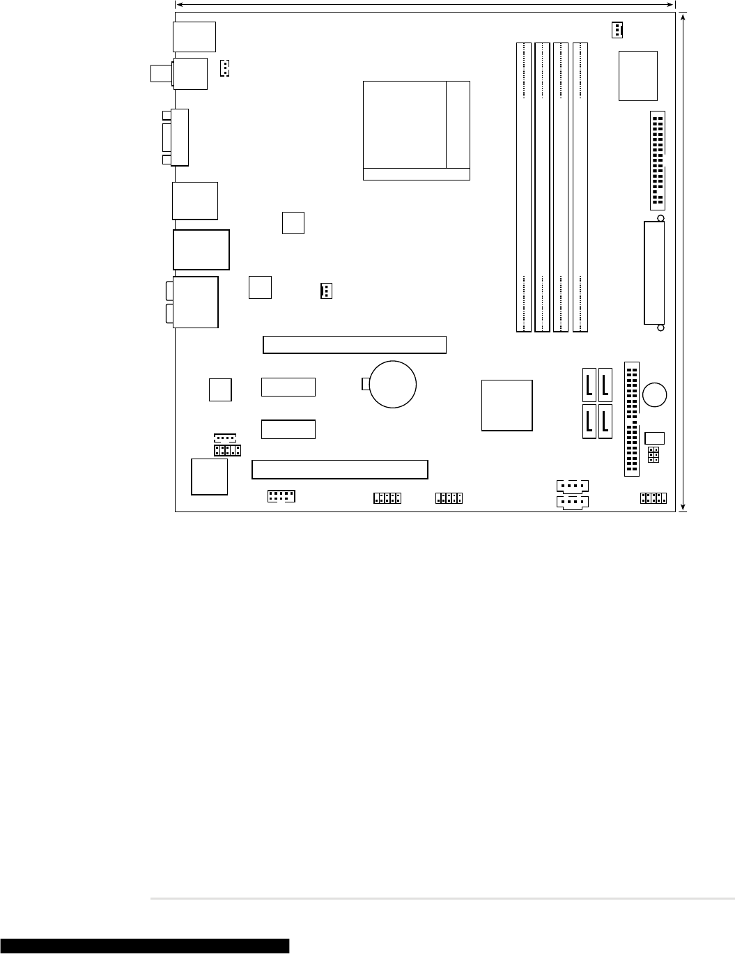
1. Motherboard layout
PCIE_X1_1
M2N68-LA
PS/2KBMS
T: Mouse
B: Keyboard
ALC888
CLEAR CMOS
CLEAR P.W
F_USB1
PC2
BUZZER
F_PANEL
F_USB2
Super
I/O
Asus
F8000
F_AUDIO
F_LINE_IN
ATXPOWER
Socket AM2
CR2032 3V
Lithium Cell
CMOS Power
NVIDIA®
MCP61P
PCIE_X16
SATA4
SATA3
RTL8201N
DDR2 XMM1 (64 bit,240-pin module)
DDR2 XMM2 (64 bit,240-pin module)
PRIMARY_IDE
FLOPPY
CPU_FAN
ATX_CPU
CHASSIS_FAN1
VGA
24.5cm (9.6in)
24.5cm (9.6in)
SATA1
SATA2
DDR2 XMM3 (64 bit,240-pin module)
DDR2 XMM4 (64 bit,240-pin module)
F_1394
agere
L-FW3227-100
1394+USB
LAN+USB
AUDIO
SPDIF_OUT
SPDIF_OUT
BIOS
F_USB3
F_USB4
PCIE_X1_2

2 M2N68-LA (Narra 3)
2. Central Processing Unit (CPU)
2.1 Overview
Themotherboardcomeswitha940-pinAM2socketdesignedfortheAMDAthlon™
64/ Athlon™ 64 X2/Sempron™ Rev F/Rev G 89W processor.
2.2 Installing the CPU
ToinstallaCPU:
1. Locate the CPU socket on the motherboard.
Makesurethatthesocketleverislifteduptoa90ºangle;otherwise,theCPU
willnottincompletely.
2. Unlock the socket by pressing the
leversideways,thenliftituptoa
90ºangle.
TheAM2sockethasadifferentpinoutfromthe940-pinsocketdesignedforthe
AMD Opteron™processor.MakesureyouuseaCPUdesignedfortheAM2
socket.TheCPUtsinonlyonecorrectorientation.DONOTforcetheCPUinto
the socket to prevent bending the connectors on the socket and damaging the
CPU!
Socket lever
M2N68-LA
M2N68-LA CPU Socket AM2
M2N68-LA (Narra 3) 3
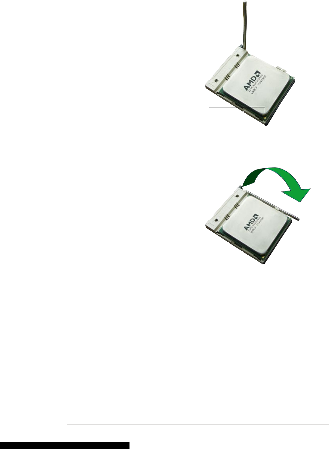
3. Position the CPU above the socket
suchthattheCPUcornerwiththe
gold triangle matches the socket
corner with a small triangle.
4. CarefullyinserttheCPUintothe
socketuntilittsinplace.
Gold triangle
Small triangle
5. WhentheCPUisinplace,push
downthesocketlevertosecurethe
CPU.Theleverclicksonthesidetab
to indicate that it is locked.
6. Install a CPU heatsink and fan
followingtheinstructionsthatcame
with the heatsink package.
4 M2N68-LA (Narra 3)
3. System memory
ThemotherboardcomeswithfourDoubleDataRate2(DDR2)DualInlineMemory
Modules(DIMM)sockets.
ADDR2modulehasthesamephysicaldimensionsasaDDRDIMMbuthasa
240-pin footprint compared to the 184-pin DDR DIMM. DDR2 DIMMs are notched
differently to prevent installation on a DDR DIMM socket.
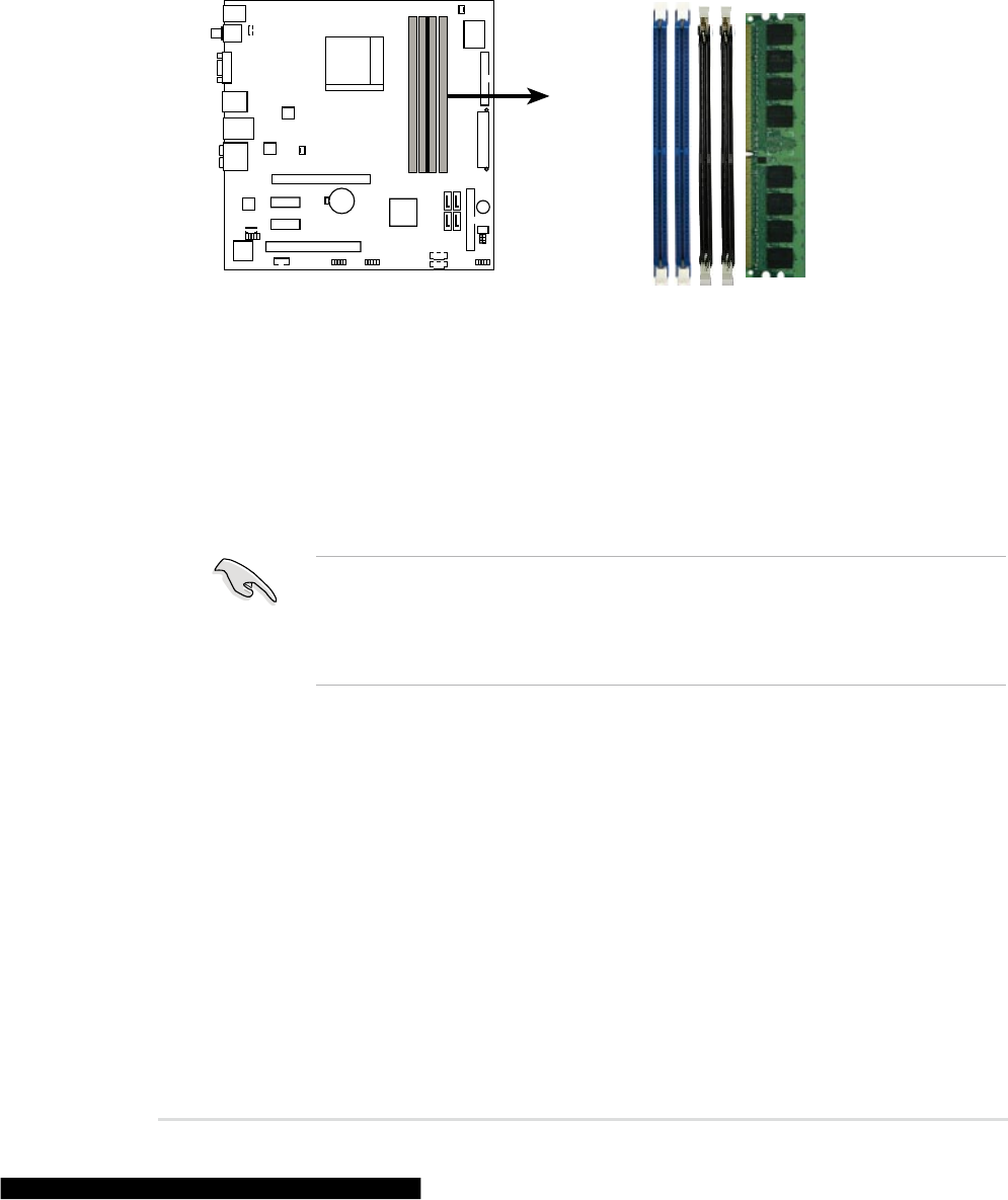
ThefollowinggureillustratesthelocationoftheDDR2DIMMsockets:
3.1 Memory congurations
Youmayinstall256MB,512MB,and1GBDDR2SDRAMDIMMsintotheDIMM
sockets.
M2N68-LA
M2N68-LA 240-pin DDR2 DIMM sockets
XMM1
XMM2
XMM3
XMM4
• Alwaysuseidentical (thesametypeandsize)DDR2DIMMpairsfordual
channelmode.Foroptimumcompatibility,werecommendthatyouobtain
memorymodulesfromthesamevendor.
• Thismotherboarddoesnotsupportdouble-sided16-bitDDRDIMMs.

M2N68-LA (Narra 3) 5
3.2 Installing a DIMM
UnplugthepowersupplybeforeaddingorremovingDIMMsorother
systemcomponents.Failuretodosocancauseseveredamagetoboththe
motherboard and the components.
• ADDR2DIMMiskeyedwithanotchsothatittsinonlyonedirection.Do
not force a DIMM into a socket to avoid damaging the DIMM.
• TheDDR2DIMMsocketsdonotsupportDDRDIMMs.DOnotinstallDDR
DIMMs to the DDR2 DIMM sockets.
3.3 Removing a DIMM
ToremoveaDIMM:
1. Simultaneouslypresstheretaining
clipsoutwardtounlocktheDIMM.
2. Remove the DIMM from the socket.
SupporttheDIMMlightlywith
yourngerswhenpressingthe
retainingclips.TheDIMMmight
getdamagedwhenitipsout
with extra force.
1
2
1DDR2 DIMM notch
ToinstallaDIMM:
1. Unlock a DIMM socket by
pressing the retaining clips
outward.
2. Align a DIMM on the socket
suchthatthenotchontheDIMM
matches the break on the socket.
3. Firmly insert the DIMM into the
socketuntiltheretainingclips
snap back in place and the
DIMM is properly seated.
Unlocked retaining clip
DDR2 DIMM notch
1
2
3
1
6 M2N68-LA (Narra 3)
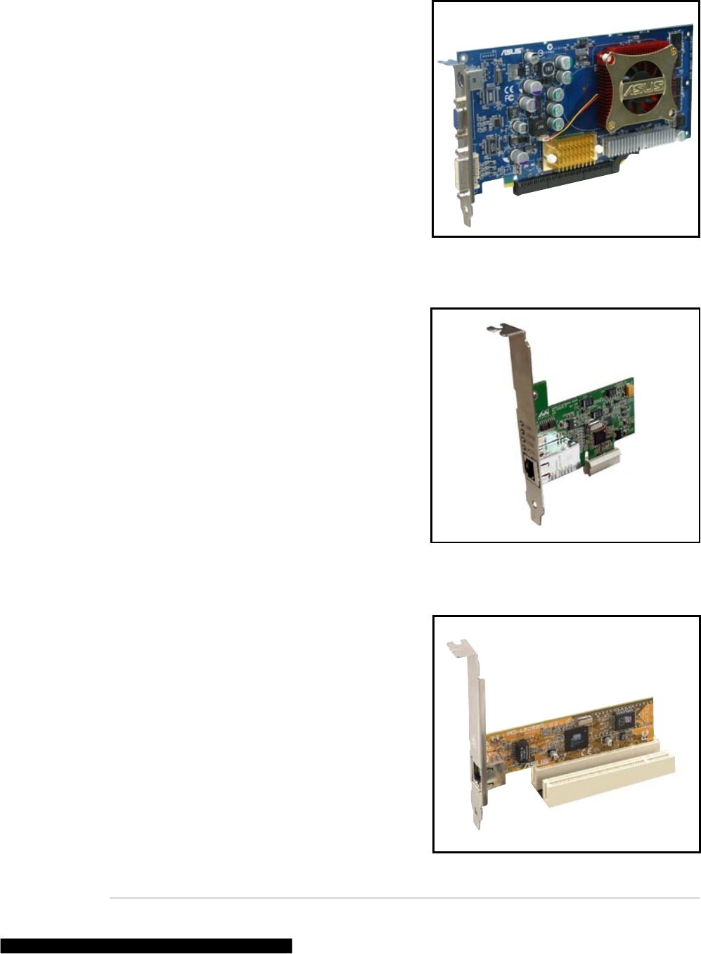
4.3 PCI slots
ThePCIslotssupportcardssuchas
aLANcard,SCSIcard,USBcard,
and other cards that comply with PCI
specications.ThegureshowsaLAN
card installed on a PCI slot.
4.1 PCI Express x16 slot
ThismotherboardsupportsPCI
Express x16 graphic cards that comply
withthePCIExpressspecications.
Thegureshowsagraphicscard
installed on the PCI Express x16 slot.
4. Expansion slots
4.2 PCI Express x1 slot
ThismotherboardsupportsPCI
Expressx1networkcards,SCSIcards
and other cards that comply with the
PCIExpressspecications.Thegure
shows a network card installed on the
PCI Express x1 slot.

M2N68-LA (Narra 3) 7
5. Jumpers
1. Clear RTC RAM (3-pin CLRTC)
ThisjumperallowsyoutocleartheRealTimeClock(RTC)RAMin
CMOS.YoucancleartheCMOSmemoryofdate,time,andsystemsetup
parametersbyerasingtheCMOSRTCRAMdata.Theonboardbutton
cellbatterypowerstheRAMdatainCMOS,whichincludesystemsetup
informationsuchassystempasswords.
ToerasetheRTCRAM:
1. TurnOFFthecomputerandunplugthepowercord.
2. Remove the onboard battery.
3. Movethejumpercapfrompins2-3(Normal)topins1-2(ClearCMOS).
Keepthecaponpins1-2forabout5~10seconds,thenmovethecap
back to pins 2-3.
4. Reinstall the battery.
5. PlugthepowercordandturnONthecomputer.
6. Holddownthe<F1>keyduringthebootprocessandenterBIOSsetup
to re-enter data.
ExceptwhenclearingtheRTCRAM,neverremovethecaponCLRTCjumper
defaultposition.Removingthecapwillcausesystembootfailure!
M2N68-LA
M2N68-LA Clear RTC RAM
CLEAR CMOS
Normal
(Default)
Clear CMOS
1
22
3

8 M2N68-LA (Narra 3)
2. Clear password (3-pin CLRPW)
Thisjumperallowsyoutoclearthepasswordifyouforgotyourpassword.
Toerasethepassword:
1. TurnOFFthecomputerandunplugthepowercord.
2. Movethejumpercapfrompins2-3(Normal)topins1-2(Clear
Password).
3. PlugthepowercordandturnONthecomputer.
4. Afterthecomputerbootsup,turnOFFthecomputer.
5. Movethejumpercapfrompins1-2topins2-3.
6. Holddownthe<F1>keyduringthebootprocessandenterBIOSsetup
to verify that the password has been cleared.
M2N68-LA
M2N68-LA Clear password setting
CLEAR P.W
Normal
(Default)
Clear Password
1
22
3

M2N68-LA (Narra 3) 9
6. Connectors
6.1 Rear panel connectors
1. PS/2 mouse port (green).ThisportisforaPS/2mouse.
2. Coaxial S/PDIF Out port.Thisportconnectsanexternalaudiooutputdevice
via a coaxial S/PDIF cable.
3. IEEE 1394a port.This6-pinIEEE1394aportproviedshigh-speed
connectivityforaudio/videodevices,storageperipherals,PCs,orportable
devices.
4. LAN (RJ-45) port.Thisportallows10/100connectiontoaLocalArea
Network(LAN)throughanetworkhub.RefertothetablebelowfortheLAN
port LED indications.
1
13
8
9
10
43
5
6
7
12 11
2
LINK
LED
ACT
LED
LAN port
LAN port LED indications
LINK LED ACT LED
Status Description Status Description
OFF No link OFF NotTransmitting
GREEN Linked ORANGE Transmitting
5. Side Speaker Out port (gray).Thisportconnectstothesidespeakersinan
8-channelaudioconguration.
6. Rear Speaker Out port (black).Thisportconnectstotherearspeakersona
4-channel,6-channel,or8-channelaudioconguration.
7. Center/Subwoofer port (yellow orange).Thisportconnectsthecenter/
subwooferspeakers.
8. Line In port (light blue).Thisportconnectsthetape,CD,DVDplayer,or
otheraudiosources.
9. Line Out port (lime).Thisportconnectsaheadphoneoraspeaker.In4-
channel,6-channel,and8-channelmode,thefunctionofthisportbecomes
FrontSpeakerOut.
10. Microphone port (pink).Thisportconnectsamicrophone.

10 M2N68-LA (Narra 3)
Port Headset
2-channel 4-channel 6-channel 8-channel
LightBlue Line In Line In Line In Line In
Lime LineOut FrontSpeakerOut FrontSpeakerOut FrontSpeakerOut
Pink Mic In Mic In Mic In Mic In
Orange – – Center/Subwoofer Center/Subwoofer
Black – RearSpeakerOut RearSpeakerOut RearSpeakerOut
Gray – – – SideSpeakerOut
Audio 2, 4, 6, or 8-channel conguration
Refertotheaudiocongurationtableforthefunctionoftheaudioportsin2,4,
6,or8-channelconguration.
11. USB 2.0 ports.Thesefour4-pinUniversalSerialBus(USB)portsare
available for connecting USB 2.0 devices.
12. VGA port.This15-pinVGAportconnectstoaVGAmonitor.
13. PS/2 keyboard port (purple).ThisportisforaPS/2keyboard.

M2N68-LA (Narra 3) 11
6.2 Internal connectors
Thissectiondescribesandillustratestheinternalconnectorsonthemotherboard.
1. Floppy disk drive connector (34-1 pin FLOPPY)
Thisconnectorisfortheprovidedoppydiskdrive(FDD)signalcable.Insert
oneendofthecabletothisconnector,thenconnecttheotherendtothe
signalconnectoratthebackoftheoppydiskdrive.
Pin 5 on the connector is removed to prevent incorrect cable connection when
usingaFDDcablewithacoveredPin5.
M2N68-LA
NOTE: Orient the red markings on
the floppy ribbon cable to PIN 1.
M2N68-LA Floppy disk drive connector
FLOPPY
PIN 1
12 M2N68-LA (Narra 3)
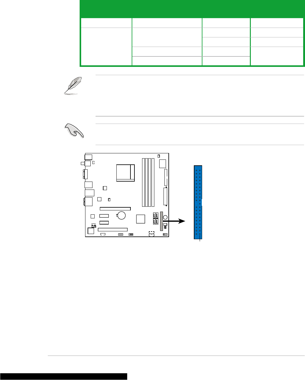
2. IDE connector (40-1 pin PRIMARY_IDE)
TheonboardIDEconnectorisfortheUltraDMA133/100/66signalcable.
TherearethreeconnectorsoneachUltraDMA133/100/66signalcable:
blue,black,andgray.Connecttheblueconnectortothemotherboard’sIDE
connector,thenselectoneofthefollowingmodestocongureyourdevice.
• Pin 20 on the IDE connector is removed to match the covered hole on the
UltraDMAcableconnector.Thispreventsincorrectinsertionwhenyou
connect the IDE cable.
• Usethe80-conductorIDEcableforUltraDMA100/66IDEdevices.
Ifanydevicejumperissetas“Cable-Select,”makesureallotherdevice
jumpershavethesamesetting.
Drive jumper setting Mode of
device(s) Cable connector
Single device Cable-Select or Master - Black
Twodevices
Cable-Select Master Black
Slave Gray
Master Master Black or gray
Slave Slave
M2N68-LA
M2N68-LA IDE connector
NOTE: Orient the red markings
(usually zigzag) on the IDE
ribbon cable to PIN 1.
PRIMARY_IDE
PIN 1

M2N68-LA (Narra 3) 13
3. ATX power connectors (24-pin ATXPOWER, 4-pin ATX_CPU)
TheseconnectorsareforATXpowersupplyplugs.Thepowersupplyplugs
aredesignedtottheseconnectorsinonlyoneorientation.Findtheproper
orientationandpushdownrmlyuntiltheconnectorscompletelyt.
M2N68-LA
M2N68-LA ATX power connectors
ATXPOWER
ATX_CPU
+3 Volts
+3 Volts
Ground
+5 Volts
+5 Volts
Ground
Ground
Power OK
+5V Standby
+12 Volts
-5 Volts
+5 Volts
+3 Volts
-12 Volts
Ground
Ground
Ground
PSON#
Ground
+5 Volts
+12 Volts
+3 Volts
+5 Volts
Ground
+12V DC
GND
+12V DC
GND
• Donotforgettoconnectthe4-pinATX+12Vpowerplug;otherwise,the
systemwillnotbootup.
• MakesurethatyourATX12Vpowersupplycanprovide8Aonthe+12V
leadandatleast1Aonthe+5-voltstandbylead(+5VSB).Theminimum
recommendedwattageis230W,or300Wforafullyconguredsystem.
Thesystemcanbecomeunstableandmightexperiencedifcultypowering
upifthepowersupplyisinadequate.
• UseofaPSUwithahigherpoweroutputisrecommendedwhen
conguringasystemwithmorepower-consumingdevices.Thesystem
maybecomeunstableormaynotbootupifthepowerisinadequate.

14 M2N68-LA (Narra 3)
M2N68-LA
M2N68-LA SATA connectors
GND
RSATA_TXP1
RSATA_TXN1
GND
RSATA_RXP1
RSATA_RXN1
GND
SATA1
GND
RSATA_TXP2
RSATA_TXN2
GND
RSATA_RXP2
RSATA_RXN2
GND SATA2
GND
RSATA_TXP4
RSATA_TXN4
GND
RSATA_RXP4
RSATA_RXN4
GND GND
RSATA_TXP3
RSATA_TXN3
GND
RSATA_RXP3
RSATA_RXN3
GND
SATA4 SATA3
4. Serial ATA connectors (7-pin SATA1, SATA2, SATA3, SATA4)
TheseconnectorsarefortheSerialATAsignalcablesforSerialATAharddisk
drives.
YoumustinstallWindows® 2000 Service Pack 4 or the Windows® XP Service
Pack1beforeusingSerialATAharddiskdrive.
5. USB connectors (10-1 pin P24 F_USB1, 10-1 pin P150 F_USB2,
5-1 pin P151 F_USB1, 5-1 pin P152 F_USB2)
TheseconnectorsareforUSB2.0ports.ConnecttheUSB/GAMEmodule
cabletoanyoftheseconnectors,theninstallthemoduletoaslotopeningat
thebackofthesystemchassis.TheseUSBconnectorscomplywithUSB2.0
specicationthatsupportsupto480Mbpsconnectionspeed.
M2N68-LA
M2N68-LA USB 2.0 connectors
F_USB1 F_USB2
USB+5V
USB_P5-
USB_P5+
GND
USB+5V
USB_P6-
USB_P6+
GND
NC
USB+5V
USB_P5-
USB_P5+
GND
USB+5V
USB_P6-
USB_P6+
GND
NC
Never connect a 1394 cable to the USB connectors. Doing so will damage the
motherboard!

M2N68-LA (Narra 3) 15
6. CPU and Chassis fan connectors (3-pin CPU_FAN,
3-pin CHASSIS_FAN1)
Thefanconnectorssupportcoolingfansof350mA~740mA(8.88Wmax.)or
atotalof1A~2.22A(26.64Wmax.)at+12V.Connectthefancablestothefan
connectorsonthemotherboard,makingsurethattheblackwireofeachcable
matchesthegroundpinoftheconnector.
M2N68-LA
M2N68-LA Fan connectors
CPU_FAN
CHASSIS_FAN1
GND
Rotation
+12V
GND
Rotation
+12V
Donotforgettoconnectthefancablestothefanconnectors.Insufcientair
owinsidethesystemmaydamagethemotherboardcomponents.Theseare
notjumpers!DONOTplacejumpercapsonthefanconnectors.
M2N68-LA
M2N68-LA Front audio connector
F_AUDIO
AUD_GND
AUD_VCC
AUD_RET_R
AUD_VCC
AUD_RET_L
AUD_MIC1
AUD_MIC2
AUD_FPOUT_R
AUD_MIC_JD
AUD_FPOUT_L
PIN1
7. Front panel audio connector (10-1 pin F_AUDIO)
Thisconnectorisforachassis-mountedfrontpanelaudioI/Omodulethat
supportsAzaliaaudiostandard.

16 M2N68-LA (Narra 3)
8. Internal audio connector (4-pin F_LINE_IN)
Thisconnectorallowsyoutoreceivestereoaudioinputfromsoundsources
suchasaCD-ROM,TVtuner,orMPEGcard.
M2N68-LA
M2N68-LA Internal audio connector
F_LINE_IN

M2N68-LA (Narra 3) 17
9. System panel connector (10-1 pin F_PANEL)
Thisconnectorsupportsseveralchassis-mountedfunctions.
M2N68-LA
M2N68-LA System panel connector
F_PANEL
PLED-
PWR
PLED+
Ground
GNDReset
HDLED+
HDLED-
HD LED RESET
PWR LED PWR BTN
NC
•
System power LED (2-pin PLED)
This2-pinconnectorisforthesystempowerLED.Connectthechassispower
LEDcabletothisconnector.ThesystempowerLEDlightsupwhenyouturn
onthesystempower,andblinkswhenthesystemisinsleepmode.
•
Hard disk drive activity LED (2-pin HDLED)
This2-pinconnectorisfortheHDDActivityLED.ConnecttheHDDActivity
LEDcabletothisconnector.TheIDELEDlightsuporasheswhendatais
readfromorwrittentotheHDD.
•
ATX power button/soft-off button (2-pin PWR)
Thisconnectorisforthesystempowerbutton.Pressingthepowerbutton
turnsthesystemonorputsthesysteminsleeporsoft-offmodedepending
ontheBIOSsettings.Pressingthepowerswitchformorethanfourseconds
whilethesystemisONturnsthesystemOFF.
•
Reset button (2-pin RESET)
This2-pinconnectorisforthechassis-mountedresetbuttonforsystem
rebootwithoutturningoffthesystempower.

18 M2N68-LA (Narra 3)
