Asus P6T Deluxe V2 Users Manual
2015-11-12
: Asus Asus-P6T-Deluxe-V2-Users-Manual-819950 asus-p6t-deluxe-v2-users-manual-819950 asus pdf
Open the PDF directly: View PDF ![]() .
.
Page Count: 182 [warning: Documents this large are best viewed by clicking the View PDF Link!]
- Contents
- Chapter 1: Product introduction
- Chapter 2: Hardware information
- Chapter 3: BIOS setup
- 3.1 Managing and updating your BIOS
- 3.2 BIOS setup program
- 3.3 Main menu
- 3.4 Ai Tweaker menu
- 3.4.1 Ai Overclock Tuner [Auto]
- 3.4.2 CPU Ratio Setting [Auto]
- 3.4.3 Intel(R) SpeedStep(TM) Tech [Enabled]
- 3.4.4 Intel(R) Turbo Mode Tech [Enabled]
- 3.4.5 DRAM Frequency [Auto]
- 3.4.6. DRAM Timing Control [Auto]
- 3.4.7 CPU Voltage [Auto]
- 3.4.8 CPU PLL Voltage [Auto]
- 3.4.9 QPI/DRAM Core Voltage [Auto]
- 3.4.10 IOH Voltage [Auto]
- 3.4.11 IOH PCIE Voltage [Auto]
- 3.4.12 ICH Voltage [Auto]
- 3.4.13 ICH PCIE Voltage [Auto]
- 3.4.14 DRAM Bus Voltage [Auto]
- 3.4.15 DRAM DATA REF Voltage on CHA/B/C [Auto]
- 3.4.16 DRAM CTRL REF Voltage on CHA/B/C [Auto]
- 3.4.17 Load-Line Calibration [Auto]
- 3.4.18 CPU Differential Amplitude [Auto]
- 3.4.19 CPU Clock Skew [Auto]
- 3.4.20 CPU Spread Spectrum [Auto]
- 3.4.21 IOH Clock Skew [Auto]
- 3.4.22 PCIE Spread Spectrum [Auto]
- 3.5 Advanced menu
- 3.6 Power menu
- 3.7 Boot menu
- 3.8 Tools menu
- 3.9 Exit menu
- Chapter 4: Software support
- Chapter 5: Multiple GPU technology support

Motherboard
P6T Deluxe V2

ii
E4398
First Edition
December 2008
Copyright © 2008 ASUSTeK COMPUTER INC. All Rights Reserved.
No part of this manual, including the products and software described in it, may be reproduced,
transmitted, transcribed, stored in a retrieval system, or translated into any language in any form or by any
means, except documentation kept by the purchaser for backup purposes, without the express written
permission of ASUSTeK COMPUTER INC. (“ASUS”).
Product warranty or service will not be extended if: (1) the product is repaired, modied or altered, unless
such repair, modication of alteration is authorized in writing by ASUS; or (2) the serial number of the
product is defaced or missing.
ASUS PROVIDES THIS MANUAL “AS IS” WITHOUT WARRANTY OF ANY KIND, EITHER EXPRESS
OR IMPLIED, INCLUDING BUT NOT LIMITED TO THE IMPLIED WARRANTIES OR CONDITIONS OF
MERCHANTABILITY OR FITNESS FOR A PARTICULAR PURPOSE. IN NO EVENT SHALL ASUS, ITS
DIRECTORS, OFFICERS, EMPLOYEES OR AGENTS BE LIABLE FOR ANY INDIRECT, SPECIAL,
INCIDENTAL, OR CONSEQUENTIAL DAMAGES (INCLUDING DAMAGES FOR LOSS OF PROFITS,
LOSS OF BUSINESS, LOSS OF USE OR DATA, INTERRUPTION OF BUSINESS AND THE LIKE),
EVEN IF ASUS HAS BEEN ADVISED OF THE POSSIBILITY OF SUCH DAMAGES ARISING FROM ANY
DEFECT OR ERROR IN THIS MANUAL OR PRODUCT.
SPECIFICATIONS AND INFORMATION CONTAINED IN THIS MANUAL ARE FURNISHED FOR
INFORMATIONAL USE ONLY, AND ARE SUBJECT TO CHANGE AT ANY TIME WITHOUT NOTICE,
AND SHOULD NOT BE CONSTRUED AS A COMMITMENT BY ASUS. ASUS ASSUMES NO
RESPONSIBILITY OR LIABILITY FOR ANY ERRORS OR INACCURACIES THAT MAY APPEAR IN THIS
MANUAL, INCLUDING THE PRODUCTS AND SOFTWARE DESCRIBED IN IT.
Products and corporate names appearing in this manual may or may not be registered trademarks or
copyrights of their respective companies, and are used only for identication or explanation and to the
owners’ benet, without intent to infringe.

iii
Contents
Contents ...................................................................................................... iii
Notices ....................................................................................................... viii
Safety information ...................................................................................... ix
About this guide .......................................................................................... x
P6T Deluxe V2 specications summary .................................................. xii
Chapter 1: Product introduction
1.1 Welcome! ...................................................................................... 1-1
1.2 Package contents ......................................................................... 1-1
1.3 Special features ............................................................................ 1-2
1.3.1 Product highlights ........................................................... 1-2
1.3.2 ASUS Unique features ................................................... 1-3
Chapter 2: Hardware information
2.1 Before you proceed ..................................................................... 2-1
2.2 Motherboard overview ................................................................. 2-2
2.2.1 Motherboard layout ......................................................... 2-2
2.2.2 Layout contents ............................................................... 2-3
2.2.3 Placement direction ........................................................ 2-4
2.2.4 Screw holes .................................................................... 2-4
2.3 Central Processing Unit (CPU) ................................................... 2-5
2.3.1 Installing the CPU ........................................................... 2-6
2.3.2 Installing the CPU heatsink and fan ................................ 2-9
2.3.3 Uninstalling the CPU heatsink and fan ......................... 2-10
2.3.4 Installing the optional fans .............................................2-11
2.4 System memory ......................................................................... 2-12
2.4.1 Overview ....................................................................... 2-12
2.4.2 Memory congurations .................................................. 2-13
2.4.3 Installing a DIMM .......................................................... 2-19
2.4.4 Removing a DIMM ........................................................ 2-19
2.5 Expansion slots .......................................................................... 2-20
2.5.1 Installing an expansion card ......................................... 2-20
2.5.2 Conguring an expansion card ..................................... 2-20
2.5.3 Interrupt assignments ................................................... 2-21
2.5.4 PCI slots ........................................................................ 2-22
2.5.5 PCI Express x4 slot ....................................................... 2-22

iv
Contents
2.5.6 PCI Express 2.0 x16 slots ............................................. 2-22
2.6 Jumpers ...................................................................................... 2-24
2.7 Onboard switches ...................................................................... 2-26
2.8 Connectors ................................................................................. 2-27
2.8.1 Rear panel connectors .................................................. 2-27
2.8.2 Internal connectors ....................................................... 2-29
2.9 Installing the additional heatsink fan ....................................... 2-40
2.10 Starting up for the rst time ...................................................... 2-41
2.11 Turning off the computer ........................................................... 2-42
2.11.1 Using the OS shut down function .................................. 2-42
2.11.2 Using the dual function power switch ............................ 2-42
Chapter 3: BIOS setup
3.1 Managing and updating your BIOS ............................................ 3-1
3.1.1 ASUS Update utility ........................................................ 3-1
3.1.2 ASUS EZ Flash 2 utility ................................................... 3-4
3.1.3 Creating a bootable oppy disk ....................................... 3-5
3.1.4 AFUDOS utility ................................................................ 3-6
3.1.5 ASUS CrashFree BIOS 3 utility ...................................... 3-8
3.2 BIOS setup program .................................................................... 3-9
3.2.1 BIOS menu screen ........................................................ 3-10
3.2.2 Menu bar ....................................................................... 3-10
3.2.3 Navigation keys ............................................................. 3-10
3.2.4 Menu items ....................................................................3-11
3.2.5 Sub-menu items .............................................................3-11
3.2.6 Conguration elds ........................................................3-11
3.2.7 Pop-up window ..............................................................3-11
3.2.8 Scroll bar ........................................................................3-11
3.2.9 General help ..................................................................3-11
3.3 Main menu .................................................................................. 3-12
3.3.1 System Time ................................................................. 3-12
3.3.2 System Date ................................................................. 3-12
3.3.3 Legacy Diskette A ........................................................ 3-12
3.3.4 Language ...................................................................... 3-12
3.3.5 SATA 1-6 ....................................................................... 3-13
3.3.6 Storage Conguration ................................................... 3-14

v
Contents
3.3.7 AHCI Conguration ....................................................... 3-15
3.3.8 System Information ....................................................... 3-16
3.4 Ai Tweaker menu ........................................................................ 3-17
3.4.1 Ai Overclock Tuner ....................................................... 3-17
3.4.2 CPU Ratio Setting ........................................................ 3-18
3.4.3 Intel(R) SpeedStep(TM) Tech ...................................... 3-18
3.4.4 Intel(R) Turbo Mode Tech ............................................. 3-18
3.4.5 DRAM Frequency ........................................................ 3-19
3.4.6. DRAM Timing Control .................................................. 3-19
3.4.7 CPU Voltage ............................................................... 3-21
3.4.8 CPU PLL Voltage ......................................................... 3-21
3.4.9 QPI/DRAM Core Voltage ............................................. 3-21
3.4.10 IOH Voltage .................................................................. 3-22
3.4.11 IOH PCIE Voltage ........................................................ 3-22
3.4.12 ICH Voltage .................................................................. 3-22
3.4.13 ICH PCIE Voltage ........................................................ 3-22
3.4.14 DRAM Bus Voltage ...................................................... 3-22
3.4.15 DRAM DATA REF Voltage on CHA/B/C ....................... 3-23
3.4.16 DRAM CTRL REF Voltage on CHA/B/C ...................... 3-23
3.4.17 Load-Line Calibration ................................................... 3-23
3.4.18 CPU Differential Amplitude ........................................... 3-23
3.4.19 CPU Clock Skew .......................................................... 3-23
3.4.20 CPU Spread Spectrum ................................................ 3-24
3.4.21 IOH Clock Skew ........................................................... 3-24
3.4.22 PCIE Spread Spectrum ................................................ 3-24
3.5 Advanced menu ......................................................................... 3-25
3.5.1 CPU Conguration ........................................................ 3-25
3.5.2 Chipset .......................................................................... 3-28
3.5.3 Onboard Device Conguration ...................................... 3-29
3.5.4 USB Conguration ........................................................ 3-30
3.5.5 PCIPnP ......................................................................... 3-31
3.6 Power menu ................................................................................ 3-32
3.6.1 Suspend Mode ............................................................. 3-32
3.6.2 Repost Video on S3 Resume ........................................ 3-32
3.6.3 ACPI 2.0 Support ......................................................... 3-32

vi
Contents
3.6.4 ACPI APIC Support ...................................................... 3-32
3.6.5 APM Conguration ........................................................ 3-33
3.6.6 Hardware Monitor ......................................................... 3-34
3.7 Boot menu .................................................................................. 3-36
3.7.1 Boot Device Priority ...................................................... 3-36
3.7.2 Boot Settings Conguration .......................................... 3-37
3.7.3 Security ......................................................................... 3-38
3.8 Tools menu ................................................................................. 3-40
3.8.1 ASUS EZ Flash 2 .......................................................... 3-40
3.8.2 Express Gate ............................................................... 3-41
3.8.3 ASUS O.C. Prole ......................................................... 3-42
3.8.4 Ai Net 2 ......................................................................... 3-43
3.9 Exit menu .................................................................................... 3-44
Chapter 4: Software support
4.1 Installing an operating system ................................................... 4-1
4.2 Support DVD information ............................................................ 4-1
4.2.1 Running the support DVD ............................................... 4-1
4.2.2 Drivers menu ................................................................... 4-2
4.2.3 Utilities menu .................................................................. 4-3
4.2.4 Make disk menu .............................................................. 4-5
4.2.5 Manual menu .................................................................. 4-6
4.2.6 ASUS Contact information .............................................. 4-6
4.2.7 Other information ............................................................ 4-7
4.3 Software information ................................................................... 4-9
4.3.1 ASUS MyLogo 2™ .......................................................... 4-9
4.3.2 AI NET2 .........................................................................4-11
4.3.3 ASUS PC Probe II ......................................................... 4-12
4.3.4 ASUS AI Suite ............................................................... 4-18
4.3.5 ASUS AI Nap ................................................................ 4-20
4.3.6 ASUS Fan Xpert ........................................................... 4-21
4.3.7 ASUS EPU–6 Engine .................................................... 4-23
4.3.8 ASUS TurboV ................................................................ 4-27
4.3.9 SoundMAX® High Denition Audio utility ....................... 4-29
4.3.10 ASUS Express Gate SSD ............................................. 4-35
4.4 RAID congurations .................................................................. 4-44

vii
Contents
4.4.1 RAID denitions ............................................................ 4-44
4.4.2 Installing Serial ATA hard disks ..................................... 4-45
4.4.3 Intel® RAID congurations ............................................. 4-45
4.5 Creating a RAID driver disk ....................................................... 4-53
4.5.1 Creating a RAID driver disk without entering the OS .... 4-53
4.5.2 Creating a RAID driver disk in Windows®...................... 4-53
Chapter 5: Multiple GPU technology support
5.1 ATI® CrossFireX™ technology .................................................... 5-1
5.1.1 Requirements .................................................................. 5-1
5.1.2 Before you begin ............................................................. 5-1
5.2 Installing CrossFireX™ graphics cards ..................................... 5-2
5.2.1 Dual CrossFireX installation ............................................ 5-2
5.2.2 Triple CrossFireX installation .......................................... 5-3
5.3 Software information ................................................................... 5-4
5.3.1 Installing the device drivers ............................................. 5-4
5.3.2 Enabling the ATI® CrossFireX™ technology ................... 5-4
5.4 NVIDIA® SLI™ Technology .......................................................... 5-6
5.4.1 Requirements .................................................................. 5-6
5.4.2 Installing SLI™ graphics cards ....................................... 5-6
5.4.3 Installing the device drivers ............................................. 5-7
5.4.4 Enabling the NVIDIA® SLI™ technology in Windows® .... 5-7

viii
Notices
Federal Communications Commission Statement
This device complies with Part 15 of the FCC Rules. Operation is subject to the
following two conditions:
•
This device may not cause harmful interference, and
•
This device must accept any interference received including interference that
may cause undesired operation.
This equipment has been tested and found to comply with the limits for a
Class B digital device, pursuant to Part 15 of the FCC Rules. These limits are
designed to provide reasonable protection against harmful interference in a
residential installation. This equipment generates, uses and can radiate radio
frequency energy and, if not installed and used in accordance with manufacturer’s
instructions, may cause harmful interference to radio communications. However,
there is no guarantee that interference will not occur in a particular installation. If
this equipment does cause harmful interference to radio or television reception,
which can be determined by turning the equipment off and on, the user is
encouraged to try to correct the interference by one or more of the following
measures:
•
Reorient or relocate the receiving antenna.
•
Increase the separation between the equipment and receiver.
•
Connect the equipment to an outlet on a circuit different from that to which the
receiver is connected.
•
Consult the dealer or an experienced radio/TV technician for help.
Canadian Department of Communications Statement
This digital apparatus does not exceed the Class B limits for radio noise emissions
from digital apparatus set out in the Radio Interference Regulations of the
Canadian Department of Communications.
This class B digital apparatus complies with Canadian ICES-003.
The use of shielded cables for connection of the monitor to the graphics card is
required to assure compliance with FCC regulations. Changes or modications
to this unit not expressly approved by the party responsible for compliance
could void the user’s authority to operate this equipment.
ix
Safety information
Electrical safety
•
To prevent electrical shock hazard, disconnect the power cable from the
electrical outlet before relocating the system.
•
When adding or removing devices to or from the system, ensure that the
power cables for the devices are unplugged before the signal cables are
connected. If possible, disconnect all power cables from the existing system
before you add a device.
•
Before connecting or removing signal cables from the motherboard, ensure
that all power cables are unplugged.
•
Seek professional assistance before using an adpater or extension cord.
These devices could interrupt the grounding circuit.
•
Make sure that your power supply is set to the correct voltage in your area.
If you are not sure about the voltage of the electrical outlet you are using,
contact your local power company.
•
If the power supply is broken, do not try to x it by yourself. Contact a
qualied service technician or your retailer.
Operation safety
•
Before installing the motherboard and adding devices on it, carefully read all
the manuals that came with the package.
•
Before using the product, make sure all cables are correctly connected and the
power cables are not damaged. If you detect any damage, contact your dealer
immediately.
•
To avoid short circuits, keep paper clips, screws, and staples away from
connectors, slots, sockets and circuitry.
•
Avoid dust, humidity, and temperature extremes. Do not place the product in
any area where it may become wet.
•
Place the product on a stable surface.
•
If you encounter technical problems with the product, contact a qualied
service technician or your retailer.
DO NOT throw the motherboard in municipal waste. This product has been
designed to enable proper reuse of parts and recycling. This symbol of the
crossed out wheeled bin indicates that the product (electrical and electronic
equipment) should not be placed in municipal waste. Check local regulations for
disposal of electronic products.
DO NOT throw the mercury-containing button cell battery in municipal waste.
This symbol of the crossed out wheeled bin indicates that the battery should not
be placed in municipal waste.

x
About this guide
This user guide contains the information you need when installing and conguring
the motherboard.
How this guide is organized
This guide contains the following parts:
• Chapter 1: Product introduction
This chapter describes the features of the motherboard and the new
technology it supports.
• Chapter 2: Hardware information
This chapter lists the hardware setup procedures that you have to perform
when installing system components. It includes description of the switches,
jumpers, and connectors on the motherboard.
• Chapter 3: BIOS setup
This chapter tells how to change system settings through the BIOS Setup
menus. Detailed descriptions of the BIOS parameters are also provided.
• Chapter 4: Software support
This chapter describes the contents of the support DVD that comes with the
motherboard package and the software.
• Chapter 5: Multiple GPU technology support
This chapter describes how to install and congure multiple ATI®
CrossFireX™ and NVIDIA SLI™ graphics cards.
Where to nd more information
Refer to the following sources for additional information and for product and
software updates.
1. ASUS websites
The ASUS website provides updated information on ASUS hardware and
software products. Refer to the ASUS contact information.
2. Optional documentation
Your product package may include optional documentation, such as warranty
yers, that may have been added by your dealer. These documents are not
part of the standard package.

xi
Conventions used in this guide
To make sure that you perform certain tasks properly, take note of the following
symbols used throughout this manual.
Typography
Bold text Indicates a menu or an item to select.
Italics
Used to emphasize a word or a phrase.
<Key> Keys enclosed in the less-than and greater-than sign
means that you must press the enclosed key.
Example: <Enter> means that you must press the
Enter or Return key.
<Key1+Key2+Key3> If you must press two or more keys simultaneously, the
key names are linked with a plus sign (+).
Example: <Ctrl+Alt+D>
Command Means that you must type the command exactly
as shown, then supply the required item or value
enclosed in brackets.
Example: At the DOS prompt, type the command line:
afudos /iP6TD.ROM
DANGER/WARNING: Information to prevent injury to yourself
when trying to complete a task.
CAUTION: Information to prevent damage to the components
when trying to complete a task.
NOTE: Tips and additional information to help you complete a
task.
IMPORTANT: Instructions that you MUST follow to complete a
task.

xii
P6T Deluxe V2 specications summary
(continued on the next page)
CPU LGA1366 socket for Intel® Core™ i7 Processor Extreme
Edition / Core™ i7 Processor
Supports Intel® Dynamic Speed Technology
* Refer to www.asus.com for Intel CPU support list
Chipset Intel® X58 / ICH10R
System Bus Up to 6.4GT/s; Intel® QuickPath Interconnect
Memory 6 x DIMM, max. 24GB, DDR3 2000(OC)* / 1866(OC)* /
1800(OC)* / 1600(OC) / 1333 / 1066 MHz, non-ECC,
un-buffered memory
Triple channel memory architecture
Supports Intel® Extreme Memory Prole (XMP)
* Hyper DIMM support is subject to the physical
characteristics of individual CPUs.
** Refer to www.asus.com or this user manual for the
Memory QVL (Qualied Vendors Lists)
Expansion Slots 3 x PCI Express 2.0 x16 slots (at x16/x16/x1 or x16/x8/x8
mode)
1 x PCI Express x4 slot
2 x PCI slots
Multi-GPU Support Supports NVIDIA® 2-Way or Quad-GPU SLI™
Technology*
Supports ATI® CrossFireX™ Technology
Storage Intel® ICH10R Southbridge:
- 6 x SATA 3.0 Gb/s ports
- Intel® Matrix Storage supporting SATA RAID 0,1,
5, and 10
Marvell 88SE6111 controller:
- 1 x Ultra DMA 133/100/66 for up to 2 PATA devices
- 1 x External SATA 3.0 Gb/s port (SATA On-the-Go)
LAN Dual Gigabit LAN controllers
2 x Marvell® 88E8056 PCIe Gigabit LAN controller
featuring AI NET2
USB 14 x USB 2.0 ports (6 ports at mid-board, 8 ports at back
panel)
IEEE 1394 VIA® VT6308 controller supports 2 x IEEE 1394a ports
(one at midboard; one at back panel)
Audio ADI® AD2000B 8-channel High Denition Audio CODEC
- Supports Jack-Detection, Multi-streaming, and Front
Panel Jack-Retasking technology
- Coaxial / Optical S/PDIF out ports at back I/O
- ASUS Noise Filter

xiii
(continued on the next page)
P6T Deluxe V2 specications summary
ASUS Unique features ASUS Exclusive Features:
- ASUS TurboV
- ASUS True 16+2 Phase Power Design
- Express Gate SSD
ASUS Power Saving Solution:
- ASUS EPU-6 Engine
- ASUS AI Nap
ASUS Quiet Thermal Solution:
- ASUS Fanless Design: Wind-Flow Heat-pipe
solution
- ASUS Fanless Design: Stack Cool 2
- ASUS Fan Xpert
- ASUS Optional Fan for Water-cooling or
Passive-Cooling only
ASUS EZ DIY:
- ASUS Q-Shield
- ASUS Q-Connector
- ASUS O.C. Prole
- ASUS CrashFree BIOS 3
- ASUS EZ Flash 2
ASUS Stylish Features ASUS MyLogo 2
Multi-language BIOS
ASUS Exclusive
Overclocking Features
ASUS TurboV utility
Precision Tweaker 2:
- vCore: Adjustable CPU voltage at 0.00625V
increment
- vCPU PLL: 36-step reference voltage control
- vDRAM Bus: 49-step DRAM bus voltage control
- vChipset(N.B.): 31-step chipset voltage control
- vNB-PCIe: 65-step chipset-PCIe bus voltage control
SFS (Stepless Frequency Selection):
- Internal Base Clock tuning from 100MHz up to 500
MHz at 1MHz increment
- PCI Express frequency tuning from 100MHz up to
180MHz at 1MHz increment
Overclocking Protection:
- ASUS C.P.R.(CPU Parameter Recall)

xiv
P6T Deluxe V2 specications summary
*Specications are subject to change without notice.
Back Panel I/O Ports 1 x PS/2 Keyboard / Mouse combo port
1 x S/PDIF Out (Coaxial + Optical)
1 x External SATA
1 x IEEE1394a
2 x RJ45 ports
8 x USB 2.0/1.1
8-channel Audio I/O
Internal I/O Connectors 3 x USB connectors support additional 6 USB ports
1 x Floppy disk drive connector
1 x IDE connector
6 x SATA connectors
1 x CPU Fan connector
3 x Chassis Fan connectors
1 x Power Fan connector
1 x IEEE1394a connector
Front panel audio connector
1 x S/PDIF Out Header
Chassis Intrusion connector
CD audio in
24-pin ATX Power connector
8-pin EATX 12V Power connectors
System Panel (Q-Connector)
1 x TPM connector
1 x Power on switch
1 x Reset switch
BIOS Features 16 Mb AMI BIOS, PnP, DMI 2.0, WfM 2.0, SM BIOS
2.4, Multi-language BIOS
Manageability WOL by PME, WOR by PME, Chassis Intrusion, PXE
Support DVD Contents Drivers
ASUS PC Probe II
ASUS Update
ASUS AI Suite
Image-Editing Suite
Anti-virus software (OEM version)
Form Factor ATX Form Factor, 12”x 9.6” (30.5cm x 24.4cm)

1
Chapter 1: Product
introduction
This chapter describes the motherboard
features and the new technologies it
supports.

ASUS P6T Deluxe V2
Chapter summary 1
1.1 Welcome! ...................................................................................... 1-1
1.2 Package contents ......................................................................... 1-1
1.3 Special features ............................................................................ 1-2

ASUS P6T Deluxe V2 1-1
1.1 Welcome!
Thank you for buying an ASUS® P6T Deluxe V2 motherboard!
The motherboard delivers a host of new features and latest technologies, making it
another standout in the long line of ASUS quality motherboards!
Before you start installing the motherboard, and hardware devices on it, check the
items in your package with the list below.
If any of the above items is damaged or missing, contact your retailer.
1.2 Package contents
Check your motherboard package for the following items.
Motherboard ASUS P6T Deluxe V2
I/O modules 1 x 2-port USB 2.0 / 1-port IEEE1394 module
Cables 6 x Serial ATA signal cables
1 x Ultra DMA 133/100/66 cable
Accessories 1 x ASUS Q-Shield (I/O shield)
1 x Optional Fan for Water-Cooling or
Passive-Cooling only
1 x ASUS Q-Connector Kit (USB, system panel;
Retail version only)
1 x ASUS SLI bridge connector
Application DVD ASUS motherboard support DVD
Documentation User guide
1-2 Chapter 1: Product Introduction
1.3 Special features
1.3.1 Product highlights
Green ASUS
This motherboard and its packaging comply with the European Union’s Restriction
on the use of Hazardous Substances (RoHS). This is in line with the ASUS vision
of creating environment-friendly and recyclable products/packagings to safeguard
consumers’ health while minimizing the impact on the environment.
Intel® Core™ i7 Processor Extreme Edition /
Core™ i7 Processor support
This motherboard supports the latest Intel® Core™ i7 processors in LGA1366
package with integrated memory controller to support 3-channel (6 DIMMs) DDR3
memory. Supports Intel® QuickPath Interconnect (QPI) with a system bus of up
to 6.4GT/s and a max bandwidth of up to 25.6GB/s. Intel® Core™ i7 processor is
one of the most powerful and energy efcient CPUs in the world. See page 2-5 for
details.
Intel® X58 Chipset
The Intel® X58 Express Chipset is the latest chipset designed to support latest
Intel® Core™ i7 Processors and Intel’s next generation system interconnect
interface, Intel® QuickPath Interconnect (QPI), providing improved performance by
utilizing serial point-to-point links, allowing increased bandwidth and stability. It also
supports up to 36 PCI Express 2.0 lanes providing better graphics performance.
Triple-Channel DDR3 2000(OC)*/1866(OC)*/1800(OC)*/
1600(O.C.)/1333/1066 support
The motherboard supports DDR3 memory that features data transfer rates of
2000(OC)/1866(OC)/1800(OC)/1600(OC)/1333/1066 MHz to meet the higher
bandwidth requirements of the latest 3D graphics, multimedia, and Internet
applications. The triple-channel DDR3 architecture enlarges the bandwidth of your
system memory to boost system performance. See page 2-12 for details.
Hyper DIMM (DDR3 1800MHz or above) support is subject to the physical
characteristics of individual CPUs.
SLI and CrossFireX on Demand
P6T Deluxe V2 breaks the boundaries to bring you the multi-GPU choice of
either SLI™ or CrossFireX™. Expect a brand-new gaming style you’ve never
experienced before! See chapter 5 for details.
P6T Deluxe V2 supports 2-Way SLI or Quad-GPU SLI only.
ASUS P6T Deluxe V2 1-3
1.3.2 ASUS Unique features
ASUS TurboV
Feel the adrenaline rush of real-time OC—now a reality with the ASUS TurboV.
This extreme OC tool lets you set new ambitions on the OC stage with an
advanced and easy-to-use interface—allowing you to overclock without exiting
or rebooting the OS. With micro adjustments of the CPU PLL, NB, NB-PCIe, and
DRAM voltages in 0.02v intervals, there are no limits—only extreme results to
break new OC records! See page 4-27 for details.
ASUS True 16+2 Phase Power Design
The breakthrough technology of 16+2 phase VRM design is bringing to the
ASUS motherboards. 16+2 phase power design (16-phase to vCore; 2-phase to
vDRAM/QPI controller inside CPU) can reach high power efciency, dispel heat
generated by VRM module effectively, and lower more temperature compared to
other VRM solution. With the high quality power components such as low RDS (on)
MOSFETs, Ferrite core chokes with lower hysteresis loss, and 100% Japan-made
high quality conductive polymer capacitors, ASUS 16+2 phase VRM design also
ensure longer component life, minimum power loss, and help to reach the superior
overclocking score ever than before.
ASUS Express Gate SDD
Taking only 5 seconds to go online from bootup, Express Gate is the one-stop
gateway to instant fun! It's a unique motherboard built-in OS. You can utilize the
most popular Instant Messengers (IM) like MSN, Skype, Google talk, QQ, and
Yahoo! Messenger to keep in touch with friends, or quickly check on the weather
and e-mails just before leaving your house. What's more, the user-friendly picture
manager lets you view your pictures without entering Windows at anytime! See
page 4-35 for details.
The actual boot time depends on the system conguration.
ASUS Power Saving Solution
ASUS Power Saving solution intelligently and automatically provides balanced
computing power and energy consumption.
1-4 Chapter 1: Product Introduction
ASUS EPU-6 Engine
The new ASUS EPU—the world’s rst power saving engine, has been
upgraded to a new 6 engine version, which provides total system power
savings by detecting current PC loadings and intelligently moderating power
in real-time. With auto phase switching for components (which includes the
CPU, VGA card, memory, chipset, hard drives and CPU cooler / system
fans), the EPU automatically provides the most appropriate power usage via
intelligent acceleration and overclocking - helping save power and money.
See page 4-23 for details.
AI Nap
With AI Nap, the system can continue running at minimum power and noise
when you are temporarily away. To wake the system and return to the OS
environment, simply click the mouse or press a key. See page 4-20 for
details.
ASUS Quiet Thermal Solution
ASUS Quiet Thermal solution makes system more stable and enhances the
overclocking capability.
Fanless Design - Stack Cool 2
ASUS Stack Cool 2 is a fan-less and zero-noise cooling solution that lowers
the temperature of critical heat generating components. The motherboard
uses a special design on the printed circuit board (PCB) to dissipate heat
these critical components generate.
Wind-Flow Heat-pipe solution
Enjoy a super cool and quiet PC environment with the innovative Wind Flow
Thermal Design. With specically-engineered copper pipes, this thermal
design effectively manages the airow of the CPU fan and directs system
heat away from the PC—resulting in efcient heat dissipation to lower overall
system temperature and prolong system lifespans.
DO NOT uninstall the heat-pipe by yourself. Doing so may bend the tubing and
affect the heat dissipation performance.
ASUS P6T Deluxe V2 1-5
Fan Xpert
ASUS Fan Xpert intelligently allows users to adjust both the CPU and chassis
fan speed according to different ambient temperature, which is caused
by different climate conditions in different geographic regions and system
loading. Built-in variety of useful proles offer exible controls of fan speed to
achieve a quiet and cool environment. See page 4-21 for details.
Optional Fan (for Water-Cooling or Passive-Cooling only)
The optional fan is specically designed to provide sufcient airow over the
CPU power modules and chipset area when water-cooling or passive-cooling
is utilized, ensuring effective heat dissipation for the entire system. See page
2-11 for details.
ASUS Crystal Sound
This feature can enhance speech-centric applications like Skype, online game,
video conference and recording.
Noise Filter
This feature detects repetitive and stationary noises (non-voice signals) like
computer fans, air conditioners, and other background noises then eliminates
it in the incoming audio stream while recording. See page 4-31 for details.
TPM Support
This motherboard supports the Trusted Platform Module (TPM), which provides
you with enhanced data protection via high-level encryption/decryption and
ensures platform integrity. The TPM meets the Windows® Vista BitLocker™ Drive
Encryption hardware requirement for a more secure working environment. See
page 2-29 for details.
The TPM module is purchased separately.
ASUS EZ DIY
ASUS EZ DIY feature collection provides you easy ways to install computer
components, update the BIOS or back up your favorite settings.
1-6 Chapter 1: Product Introduction
ASUS Onboard Switch
With an easy press during overclock, this exclusive onboard switch allows
gamer to effortless ne-tune the performance without having to short the
pins! See page 2-26 for details.
ASUS Q-Shield
The specially designed ASUS Q-Shield provides conductivity to best protect
your motherboard against static electricity damage and shields it against
Electronic Magnetic Interference (EMI). Without the usual "ngers" present,
this new design is convenient and safe to install.
ASUS Q-Connector
ASUS Q-Connector allows you to easily connect or disconnect the chassis
front panel cables to the motherboard. This unique module eliminates the
trouble of connecting the system panel cables one at a time and avoiding
wrong cable connections. See page 2-39 for details.
ASUS O.C. Prole
The motherboard features the ASUS O.C. Prole that allows users to
conveniently store or load multiple BIOS settings. The BIOS settings can be
stored in the CMOS or a separate le, giving users freedom to share and
distribute their favorite settings. See page 3-42 for details.
ASUS CrashFree BIOS 3
The ASUS CrashFree BIOS 3 allows users to restore corrupted BIOS data
from a USB ash disk containing the BIOS le. See page 3-8 for details.
ASUS EZ Flash 2
EZ Flash 2 is a user-friendly BIOS update utility. Simply press the predened
hotkey to launch the utility and update the BIOS without entering the OS.
Update your BIOS easily without preparing a bootable diskette or using an
OS-based ash utility. See page 3-4 for details.

ASUS P6T Deluxe V2 1-7
ASUS MyLogo2™
This feature allows you to convert your favorite photo into a 256-color boot logo for
a more colorful and vivid image on your screen. See page 4-9 for details.
ASUS Multi-language BIOS
The multi-language BIOS allows you to select the language of your choice from the
available options. The localized BIOS setup menu helps you congure your system
easier and faster. See page 3-12 for details.

1-8 Chapter 1: Product Introduction
2
Chapter 2: Hardware
information
This chapter lists the hardware setup
procedures that you have to perform
when installing system components. It
includes description of the jumpers and
connectors on the motherboard.

ASUS P6T Deluxe V2
Chapter summary 2
2.1 Before you proceed ..................................................................... 2-1
2.2 Motherboard overview ................................................................. 2-2
2.3 Central Processing Unit (CPU) ................................................... 2-5
2.4 System memory ......................................................................... 2-12
2.5 Expansion slots .......................................................................... 2-20
2.6 Jumpers ...................................................................................... 2-24
2.7 Onboard switches ...................................................................... 2-26
2.8 Connectors ................................................................................. 2-27
2.9 Installing the additional heatsink fan ....................................... 2-40
2.10 Starting up for the rst time ...................................................... 2-41
2.11 Turning off the computer ........................................................... 2-42

2.1 Before you proceed
Take note of the following precautions before you install motherboard components
or change any motherboard settings.
• Unplug the power cord from the wall socket before touching any
component.
• Use a grounded wrist strap or touch a safely grounded object or a metal
object, such as the power supply case, before handling components to
avoid damaging them due to static electricity.
• Hold components by the edges to avoid touching the ICs on them.
• Whenever you uninstall any component, place it on a grounded antistatic
pad or in the bag that came with the component.
• Before you install or remove any component, ensure that the ATX power
supply is switched off or the power cord is detached from the power
supply. Failure to do so may cause severe damage to the motherboard,
peripherals, and/or components.
ASUS P6T Deluxe V2 2-1
2.2 Motherboard overview
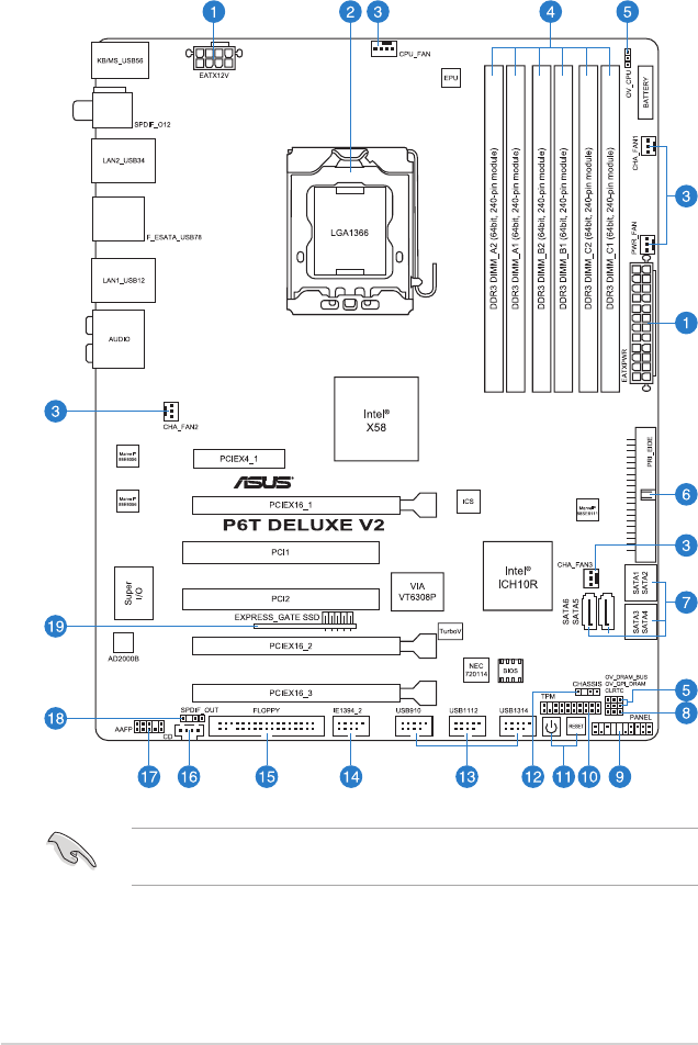
2.2.1 Motherboard layout
Refer to 2.8 Connectors for more information about rear panel connectors and
internal connectors.
2-2 Chapter 2: Hardware information

2.2.2 Layout contents
Connectors/Jumpers/Slots Page
1. ATX power connectors (24-pin EATXPWR, 8-pin EATX12V) 2-36
2. LGA1366 CPU Socket 2-6
3. CPU, chassis, and power fan connectors (4-pin CPU_FAN,
3-pin CHA_FAN1-3, 3-pin PWR_FAN)
2-34
4. DDR3 DIMM slots 2-12
5. CPU / DRAM Bus / QPI DRAM overvoltage settings (3-pin
OV_CPU; 3-pin OV_DRAM_BUS; 3-pin OV_QPI_DRAM)
2-25
6. IDE connector (40-1 pin PRI_EIDE) 2-30
7. ICH10R Serial ATA connectors [red] (7-pin SATA1-6) 2-31
8. Clear RTC RAM (3-pin CLRTC) 2-24
9. System panel connector (20-8 pin PANEL) 2-38
10. TPM connector (20-1 pin TPM) 2-29
11. Onboard Power-on and Reset switch 2-26
12. Chassis intrusion connector (4-1 pin CHASSIS) 2-35
13. USB connectors (10-1 pin USB910, USB1112, USB1314) 2-32
14. IEEE 1394a port connector (10-1 pin IE1394_2) 2-33
15. Floppy disk drive connector (34-1 pin FLOPPY) 2-29
16. Optical drive audio connector (4-pin CD) 2-37
17. Front panel audio connector (10-1 pin AAFP) 2-35
18. Digital audio connector (4-1 pin SPDIF_OUT) 2-37
19. Express_Gate SSD 4-35
ASUS P6T Deluxe V2 2-3
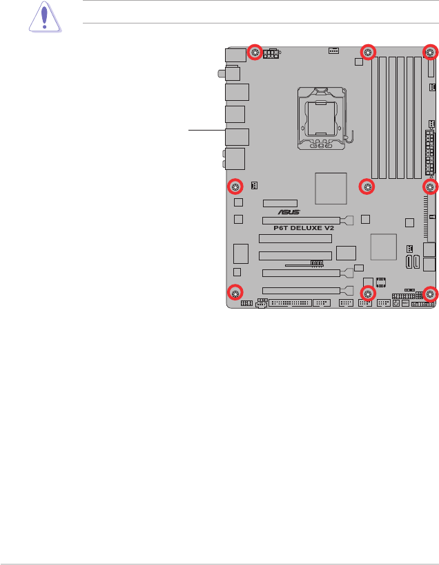
DO NOT overtighten the screws! Doing so can damage the motherboard.
2.2.3 Placement direction
When installing the motherboard, make sure that you place it into the chassis in the
correct orientation. The edge with external ports goes to the rear part of the chassis
as indicated in the image below.
2.2.4 Screw holes
Place nine (9) screws into the holes indicated by circles to secure the motherboard
to the chassis.
Place this side towards
the rear of the chassis
2-4 Chapter 2: Hardware information

2.3 Central Processing Unit (CPU)
The motherboard comes with a surface mount LGA1366 socket designed for the
Intel® Core™ i7 Processor Extreme Edition / Core™ i7 Processor.
• Upon purchase of the motherboard, make sure that the PnP cap is on
the socket and the socket contacts are not bent. Contact your retailer
immediately if the PnP cap is missing, or if you see any damage to the PnP
cap/socket contacts/motherboard components. ASUS will shoulder the cost
of repair only if the damage is shipment/transit-related.
• Keep the cap after installing the motherboard. ASUS will process Return
Merchandise Authorization (RMA) requests only if the motherboard comes
with the cap on the LGA1366 socket.
• The product warranty does not cover damage to the socket contacts
resulting from incorrect CPU installation/removal, or misplacement/loss/
incorrect removal of the PnP cap.
• Make sure that all power cables are unplugged before installing the CPU.
• Connect the chassis fan cable to the CHA_FAN1 connector to ensure
system stability.
ASUS P6T Deluxe V2 2-5
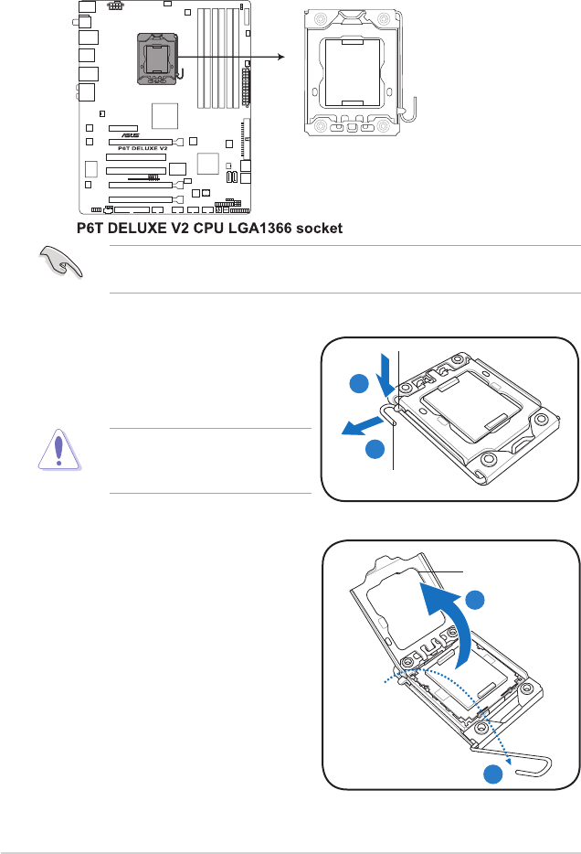
2.3.1 Installing the CPU
To install a CPU:
1. Locate the CPU socket on the motherboard.
To prevent damage to the socket
pins, do not remove the PnP cap
unless you are installing a CPU.
2. Press the load lever with your
thumb (A), then move it to the left
(B) until it is released from the
retention tab.
A
B
Load lever
Retention tab
3. Lift the load lever in the direction of
the arrow to a 135º angle.
4. Lift the load plate with your thumb
and forenger to a 100º angle.
Load plate
4
3
Before installing the CPU, make sure that the cam box is facing towards you
and the load lever is on your left.
2-6 Chapter 2: Hardware information
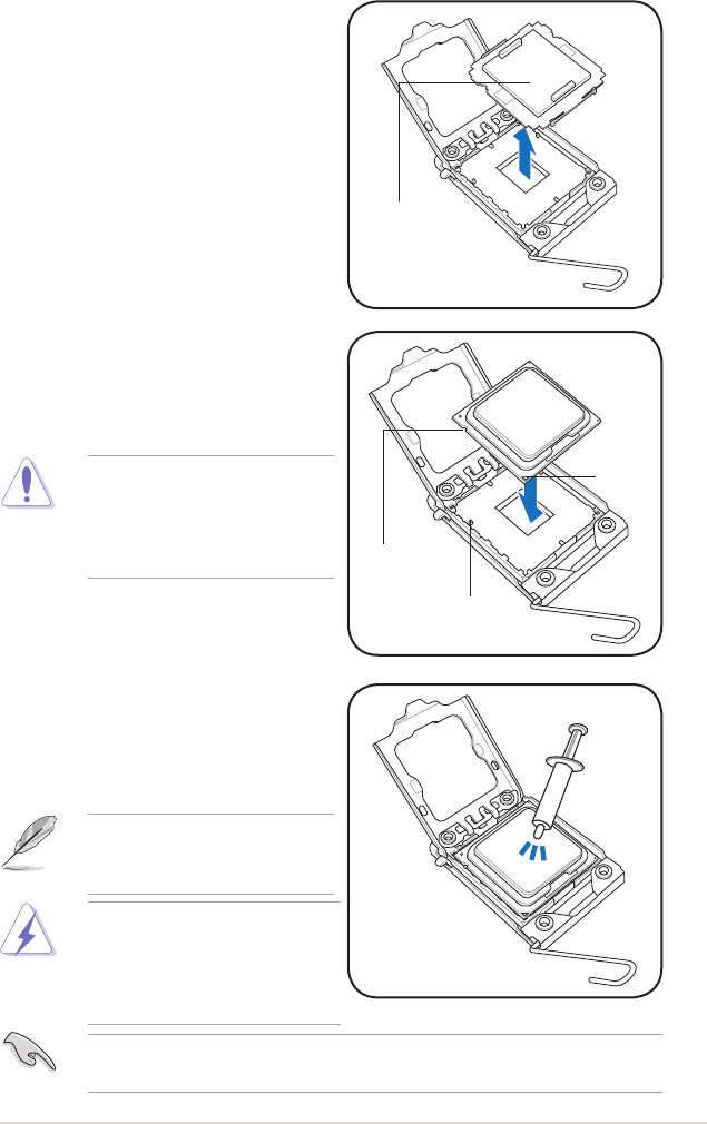
The CPU ts in only one correct
orientation. DO NOT force the
CPU into the socket to prevent
bending the connectors on the
socket and damaging the CPU!
6. Position the CPU over the socket,
making sure that the gold triangle
is on the bottom-left corner of the
socket, and then t the socket
alignment key into the CPU notch.
7. Apply several drops of thermal paste
to the exposed area of the CPU that
the heatsink will be in contact with,
ensuring that it is spread in an even
thin layer.
Some heatsinks come with pre-
applied thermal paste. If so, skip
this step.
5. Remove the PnP cap from the CPU
socket.
PnP cap
Gold
triangle
mark
Alignment key
CPU notch
The thermal paste is toxic and
inedible. If it gets into your eyes
or touches your skin, ensure to
wash it off immediately and seek
professional medical help.
To prevent contaminating the paste, DO NOT spread the paste with your nger
directly.
ASUS P6T Deluxe V2 2-7
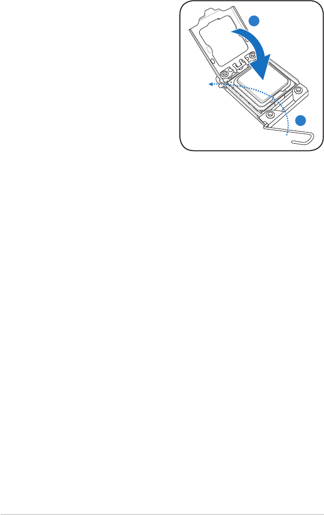
8. Close the load plate (A), and then
push the load lever (B) until it snaps
into the retention tab. A
B
2-8 Chapter 2: Hardware information
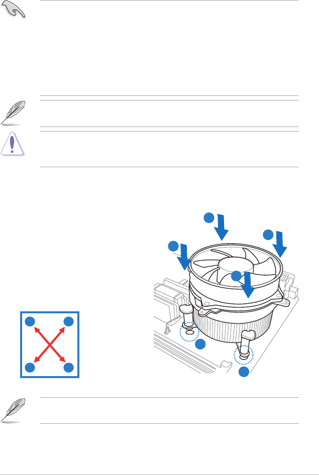
2.3.2 Installing the CPU heatsink and fan
The Intel® LGA1366 processor requires a specially designed heatsink and fan
assembly to ensure optimum thermal condition and performance.
• When you buy a boxed Intel® processor, the package includes the CPU fan
and heatsink assembly. If you buy a CPU separately, make sure that you
use only Intel®-certied multi-directional heatsink and fan.
• Your Intel® LGA1366 heatsink and fan assembly comes in a push-pin
design and requires no tool to install.
• If you purchased a separate CPU heatsink and fan assembly, make sure
that you have properly applied Thermal Interface Material to the CPU
heatsink or CPU before you install the heatsink and fan assembly.
Make sure that you have installed the motherboard to the chassis before you
install the CPU fan and heatsink assembly.
Orient the heatsink and fan assembly such that the CPU fan cable is closest to
the CPU fan connector.
To install the CPU heatsink and fan:
1. Place the heatsink on top of the
installed CPU, making sure that the
four fasteners match the holes on
the motherboard.
2. Push down two fasteners at a time
in a diagonal sequence to secure
the heatsink and fan assembly in
place.
A
A
B
B
1
1
AB
BA
If you purchased a separate CPU heatsink and fan assembly, ensure that the
Thermal Interface Material is properly applied to the CPU heatsink or CPU
before you install the heatsink and fan assembly.
ASUS P6T Deluxe V2 2-9
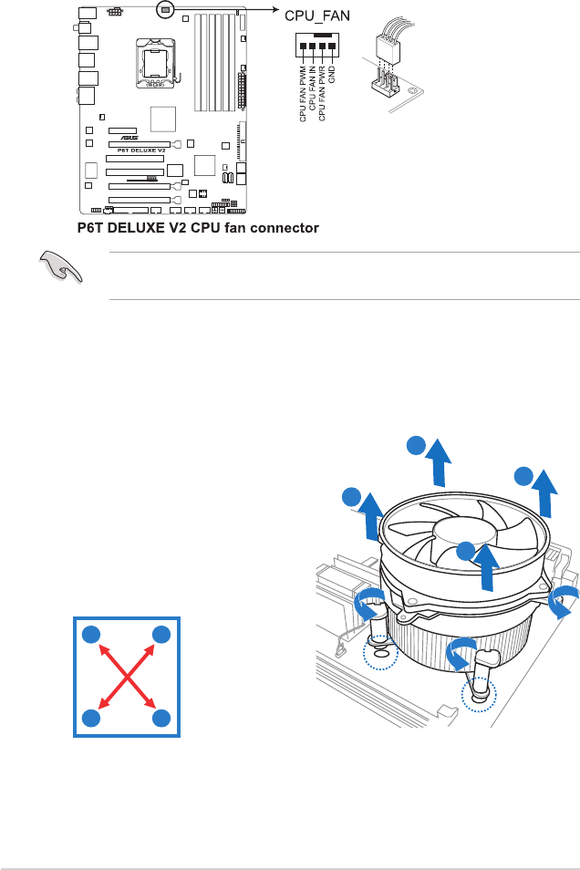
3. Connect the CPU fan cable to the connector on the motherboard labeled
CPU_FAN.
DO NOT forget to connect the CPU fan connector! Hardware monitoring errors
can occur if you fail to plug this connector.
2.3.3 Uninstalling the CPU heatsink and fan
To uninstall the CPU heatsink and fan:
1. Disconnect the CPU fan cable from
the connector on the motherboard.
2. Rotate each fastener
counterclockwise.
3. Pull up two fasteners at a time in a
diagonal sequence to disengage the
heatsink and fan assembly from the
motherboard.
A
A
B
B
A
AB
B
4. Carefully remove the heatsink and fan assembly from the motherboard.
2-10 Chapter 2: Hardware information
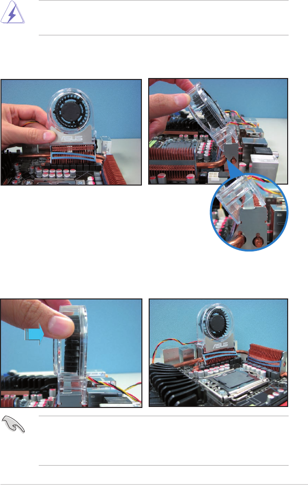
2.3.4 Installing the optional fans
Install the optional fan only if you are using a passive cooler or a water cooler.
Installing the optional fan with an active CPU cooler will interfere with the airow
and destabilize the system.
1. Position the fan above the pipe
and heatsink assembly.
2. Fit the fan to the grooved edge of
the heatsink.
3. Carefully push down the fan until
it snugly ts the heatsink, then
connect the fan cable.
4. The photo shows the fan installed
on the motherboard.
• Plug the optional fan cable to the CHA_FAN2 connector on the
motherboard.
• Make sure the optional fan is installed correctly to prevent damage to the
fan and motherboard components.
ASUS P6T Deluxe V2 2-11
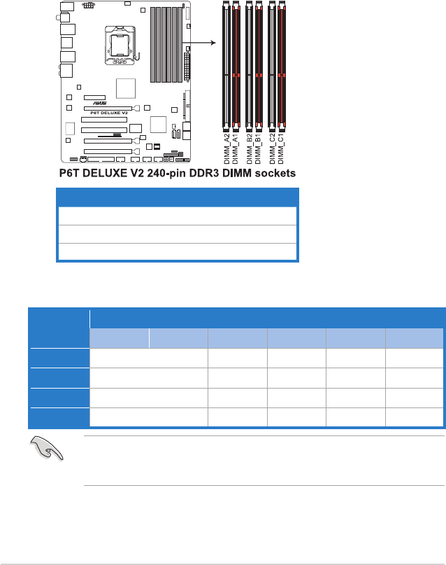
2.4 System memory
2.4.1 Overview
The motherboard comes with six Double Data Rate 3 (DDR3) Dual Inline Memory
Modules (DIMM) sockets.
A DDR3 module has the same physical dimensions as a DDR2 DIMM but is
notched differently to prevent installation on a DDR2 DIMM socket. DDR3 modules
are developed for better performance with less power consumption.
The gure illustrates the location of the DDR3 DIMM sockets:
Channel Sockets
Channel A DIMM_A1 and DIMM_A2
Channel B DIMM_B1 and DIMM_B2
Channel C DIMM_C1 and DIMM_C2
Recommended memory conguration for better performance
Mode Sockets
DIMM_A2 DIMM_A1 DIMM_B2 DIMM_B1 DIMM_C2 DIMM_C1
2 DIMMs - Populated - Populated - -
3 DIMMs - Populated - Populated - Populated
4 DIMMs Populated Populated - Populated - Populated
6 DIMMs Populated Populated Populated Populated Populated Populated
Due to Intel CPU spec denition, the system will not boot if only one DIMM is
installed in DIMM slot A2, B2, or C2. Follow the table above for recommended
memory conguration.
2-12 Chapter 2: Hardware information

2.4.2 Memory congurations
You may install 1GB and 2GB unbuffered and non-ECC DDR3 DIMMs into the
DIMM sockets.
• The default memory operation frequency is dependent on its SPD. Under
the default state, some memory modules for overclocking may operate at a
lower frequency than the vendor-marked value.
• For system stability, use a more efcient memory cooling system to support
a full memory load (6 DIMMs) or overclocking condition.
• You may install varying memory sizes in Channel A, Channel B and
Channel C. The system maps the total size of the lower-sized channel for
the dual-channel or triple-channel conguration. Any excess memory from
the higher-sized channel is then mapped for single-channel operation.
• Due to Intel spec denition, X.M.P. DIMMs and DDR3-1600 are supported
for one DIMM per channel only.
• According to Intel CPU spec, DIMMs with voltage requirement over 1.65V
may damage the CPU permanently. We recommend you install the DIMMs
with the voltage requirement below 1.65V.
• Always install DIMMs with the same CAS latency. For optimum
compatibility, we recommend that you obtain memory modules from the
same vendor.
• Due to the memory address limitation on 32-bit Windows OS, when you
install 4GB or more memory on the motherboard, the actual usable memory
for the OS can be about 3GB or less. For effective use of memory, we
recommend that you install a 64-bit Windows OS when having 4GB or
more memory installed on the motherboard.
• This motherboard does not support DIMMs made up of 256 megabit (Mb)
chips or less.
P6T Deluxe V2 Motherboard
Qualied Vendors Lists (QVL) DDR3-2000MHz capability
Vendor Part No. Size SS/
DS
Chip
Brand Chip NO. Timing
DIMM (BIOS) Voltage
DIMM socket
support (Optional)
A* B*
KINGSTON KHX16000D3K2/2GN
(EPP) 2GB (Kit of 2) SS N/A Heat-Sink
Package 2.0 • •
KINGSTON KHX16000D3K3/3GX
(XMP) 3GB (Kit of 3) SS N/A Heat-Sink
Package
(1333-9-9-
9-24) 1.65 • •
Gingle 9CAASS37AZZ01D1 2GB DS N/A Heat-Sink
Package 9-9-9-24 • •
ASUS P6T Deluxe V2 2-13

Vendor Part No. Size SS/
DS
Chip
Brand Chip NO. Timing
DIMM (BIOS) Voltage
DIMM socket
support
(Optional)
A* B*
KINGSTON KHX14900D3K3/3GX
(XMP)
3GB
(Kit of 3) SS N/A Heat-Sink Package (1333-9-9-9-24) 1.65 • •
Super
Talent W1866UX2GB 2GB
(Kit of 2) SS N/A Heat-Sink Package CL8-8-8-24
(1333-9-9-9-24) • •
Aeneon AXH760UD10-18J
(XMP) 1GB SS N/A Heat-Sink Package CL10
(1333-8-8-8-24) • •
Aeneon AXH860UD20-18J
(XMP) 2GB DS N/A Heat-Sink Package CL10
(1333-8-8-8-24) • •
P6T Deluxe V2 Motherboard
Qualied Vendors Lists (QVL) DDR3-1866MHz capability
Vendor Part No. Size SS/
DS
Chip
Brand Chip NO. Timing
DIMM (BIOS) Voltage
DIMM socket
support
(Optional)
A* B*
CORSAIR CM3X1024-
1800C7DIN (XMP) 1GB SS N/A Heat-Sink Package 7 • •
CORSAIR
BoxP/N:
TW3X4G1800C8DF
(CM3X2G1800C8D)
4GB
(Kit of 2) DS N/A Heat-Sink Package 8-8-8-24 1.80 •
KINGSTON KHX14400D3/1G 1GB SS N/A Heat-Sink Package 1.9 • •
KINGSTON KHX14400D3K3/3GX
(XMP)
3GB
(Kit of 3) SS N/A Heat-Sink Package (1333-9-9-9-24) 1.65 • •
Transcend TX1800KLU-2GK
(XMP)
2GB
(Kit of 2) SS N/A Heat-Sink Package 8 • •
Patriot PVS32G1800LLKN
(EPP)
2GB
(Kit of 2) SS N/A Heat-Sink Package CL8-8-8-20
(1066-7-7-7-20) 1.9 • •
P6T Deluxe V2 Motherboard
Qualied Vendors Lists (QVL) DDR3-1800MHz capability
Vendor Part No. Size SS/
DS
Chip
Brand Chip NO. Timing
DIMM (BIOS) Voltage
DIMM socket
support
(Optional)
A* B* D*
A-DATA AD31600E001GMU (XMP) 3GB
(kit of 3) SS N/A Heat-Sink
Package
8-8-8-24
(1333-9-9-9-24)
1.65-
1.85 • •
A-DATA AD31600E001GMU (XMP) 6GB
(kit of 3) DS N/A Heat-Sink
Package
7-7-7-20
(1333-9-9-9-24)
1.75-
1.85 •••
CORSAIR
BoxP/N:TWIN3X2048-
1600C7DHXIN
(CM3X1024-
1600C7DHXIN)(XMP)
2G
(kit of 2) SS N/A Heat-Sink
Package
7-7-7-20
(1333-9-9-9-24) 1.80 • • •
CORSAIR TR3X3G1600C8D (XMP) 3GB
(kit of 3) SS N/A Heat-Sink
Package
8-8-8-24
(1601-8-8-8-24) 1.65 • •
CORSAIR
BoxP/N:
TW3X4G1600C9DHXNV
(CM3X2G1600C9DHXNV)
4GB
(kit of 2) DS N/A Heat-Sink
Package (1333-9-9--9-24) 1.80 • • •
CORSAIR
BoxP/N:TWIN3X4096-
1600C7DHXIN
(CM3X2048-
1600C7DHXIN)
4GB
(kit of 2) DS N/A Heat-Sink
Package (1601-7-7-7-20) 1.90 • • •
P6T Deluxe V2 Motherboard
Qualied Vendors Lists (QVL) DDR3-1600MHz capability
2-14 Chapter 2: Hardware information

Vendor Part No. Size SS/
DS
Chip
Brand Chip NO. Timing
DIMM (BIOS) Voltage
DIMM socket
support
(Optional)
A* B* D*
CORSAIR TR3X6G1600C8D (XMP) 6GB
(kit of 3) DS N/A Heat-Sink
Package
8-8-8-24
(1601-8-8-8-24) 1.65 • • •
CORSAIR TR3X6G1600C9 (XMP) 6GB
(kit of 3) DS N/A Heat-Sink
Package
9-9-9-24
(1333-9-9-9-24) 1.65 • • •
Crucial BL12864BA1608.8SFB
(XMP) 1GB SS N/A Heat-Sink
Package (1601-8-8-8-24) 1.8 • • •
G.SKILL F3-12800CL7D-2GBHZ 2G
(kit of 2) SS N/A Heat-Sink
Package (1601-7-7-7-18) 1.9 • • •
G.SKILL F3-12800CL9D-2GBNQ 2G
(kit of 2) SS N/A Heat-Sink
Package (1333-9-9-9-24) 1.6 • • •
G.SKILL F3-12800CL7D-4GBPI 4GB
(kit of 2) DS N/A Heat-Sink
Package
7-7-7-18
(1333-9-9-9-24) 1.9 • • •
G.Skill F3-12800CL8T-
6GBHK(XMP)
6GB
(kit of 3) DS N/A Heat-Sink
Package
8-8-8-21
(1333-8-8-8-21)
1.6-
1.65 • • •
G.SKILL F3-12800CL9T-6GBNQ 6GB
(kit of 3) DS N/A Heat-Sink
Package
9-9-9-24
(1601-9-9-9-24) 1.5-1.6 • • •
KINGSTON KHX12800D3LLK3/
3GX(XMP)
3GB
(kit of 3) SS N/A Heat-Sink
Package (1333-9-9-9-24) 1.65 • •
KINGSTON KHX12800D3K2/4G 4GB
(kit of 2) SS N/A Heat-Sink
Package (1066-7-7-7-20) 1.9 • •
OCZ OCZ3P1600EB1G 1GB SS N/A Heat-Sink
Package
7-6-6-24
(1333-7-7-7-20) •
OCZ OCZ3P16002GK 2G
(kit of 2) SS N/A Heat-Sink
Package
7
(1333-7-7-7-20) •
OCZ OCZ3T1600XM2GK(XMP) 2G
(kit of 2) SS N/A Heat-Sink
Package (1601-8-8-8-28) • • •
OCZ OCZ3P1600EB4GK 4GB
(kit of 2) DS N/A Heat-Sink
Package
7-7-6
(1333-7-7-7-20) 1.8 • • •
Aeneon AXH760UD10-16H 1GB SS N/A Heat-Sink
Package (1601-9-9-9-28) • • •
Aeneon AXH860UD20-16H 2G DS N/A Heat-Sink
Package (1601-9-9-9-28) • • •
Cell Shock CS322271 2G
(kit of 2) DS N/A Heat-Sink
Package
7-7-7-14
(1066-7-7-7-20) 1.7-1.9 • • •
Elixier M2F2G64CB8HA4N-DG 2G DS Elixir N2CB1680AN-
DG
9
(1333-9-9-9-28) • • •
Mushkin 996657 4GB
(kit of 2) DS N/A Heat-Sink
Package 7-7-7-20 • • •
Patriot PVT33G1600ELK 3GB
(kit of 3) SS N/A Heat-Sink
Package
9-9-9-24
(1066-7-7-7-20) 1.65 • • •
Patriot PVS34G1600LLKN 4GB
(kit of 2) DS N/A Heat-Sink
Package
7-7-7-20
(1066-7-7-7-20) 2.0 • • •
Patriot PVT36G1600ELK 6GB
(kit of 3) DS N/A Heat-Sink
Package
9-9-9-24
(1066-7-7-7-20) 1.65 • • •
PQI MFADR401PA0102 2G DS SAMSUNG K4B1G08460 9-9-9-24
(1333-9-9-9-24) • • •
Team
BoxP/N:
TXD32048M1600HC7DC
(TXD31024M1600HC7)
2G
(kit of 2) SS N/A Heat-Sink
Package
7-7-7-21
(1333-8-8-824)
1.75-
1.85 • • •
P6T Deluxe V2 Motherboard
Qualied Vendors Lists (QVL) DDR3-1600MHz capability (continued)
ASUS P6T Deluxe V2 2-15

P6T Deluxe V2 Motherboard
Qualied Vendors Lists (QVL) DDR3-1333MHz capability
• Hyper DIMM (DDR3 1800MHz or above) support is subject to the physical
characteristics of individual CPUs.
• Please load X.M.P or D.O.C.P setting in BIOS for hyper DIMM (DDR3
1800MHz or above) support.
• According to Intel spec denition, DDR3-1600 is supported for one DIMM
per channel only. ASUS exclusively provides two DDR3-1600 DIMM
support for each memory channel.
Vendor Part No. Size SS/
DS
Chip
Brand Chip NO. Timing
DIMM (BIOS) Voltage
DIMM socket support
(Optional)
A* B* C* D*
KINGSTON KVR1333D3N9/1G 1GB SS ELPIDA J1108BASE-DJ-E (1333-9-9-9-24) 1.5 • • • •
KINGSTON KVR1333D3N9/2G 2GB DS ELPIDA J1108BASE-DJ-E (1333-9-9-9-24) 1.5 • • • •
A-DATA SC63I1B16 2GB DS SAMSUNG K4B1G0846D (1333-9-9-9-24) • • • •
A-DATA AD31333E002G0U 6GB
(kit of 3) DS N/A Heat-Sink Package CL7-7-7-20
(1333-9-9-9-24)
1.65-
1.85 ••••
Apacer 78.01GC8.422 1GB SS ELPIDA J1108BABG-DJ-E
(ECC) (1333-9-9-9-24) • • • •
Apacer 78.A1GC6.421 2GB DS ELPIDA J1108BABG-DJ-E (1333-9-9-9-24) • •
Apacer 78.A1GC8.423 2GB DS ELPIDA J1108BABG-DJ-E
(ECC) (1333-9-9-9-24) • • •
CORSAIR CM3X1G1333C9D6 3GB
(kit of 3) SS N/A Heat-Sink Package 9-9-9-24
(1337-9-9-9-24) 1.5 • • • •
CORSAIR TR3X3G1333C9 3GB
(kit of 3) SS N/A Heat-Sink Package 9-9-9-24
(1333-9-9-9-24) 1.5 •
CORSAIR CM3X1024-
1333C9DHX 1GB DS N/A Heat-Sink Package (1333-9-9-9-24) 1.1 • • •
CORSAIR
BoxP/N:TWIN3X2048-
1333C9
(CM3X1024-1333C9)
2GB
(kit of 2) DS N/A Heat-Sink Package 9-9-9-24
(1066-7-7-7-20) 1.70 • • • •
CORSAIR
BoxP/N:
TW3X4G1333C9DHX
(CM3X2048-
1333C9DHX)
4GB
(kit of 2) DS N/A Heat-Sink Package 9-9-9-24
(1066-7-7-7-20) 1.70 • • •
CORSAIR CM3X2G1333C9D6 6GB
(kit of 3) DS N/A Heat-Sink Package 9-9-9-24
(1337-9-9-9-24) 1.5 • • • •
CORSAIR TR3X6G1333C9 6GB
(kit of 3) DS N/A Heat-Sink Package 9-9-9-24
(1333-9-9-9-24) 1.5 • • • •
Crucial CT12864BA1339.8SFB 1GB SS MICRON D9GTS (1333-9-9-9-24) • • •
Crucial CT12864BA1339.8SFD 1GB SS MICRON MT8JF12864AY-
1G4D1 (1333-9-9-9-24) • • • •
Crucial CT25664BA1339.16SFD 2GB DS MICRON D9JNM (1333-9-9-9-24) • •
ELPIDA EBJ10UE8BAW0-DJ-E 1GB SS ELPIDA J1108BABG-DJ-E CL9
(1333-9-9-9-24) •••
ELPIDA EBJ21UE8BAW0-DJ-E 2GB DS ELPIDA J1108BABG-DJ-E CL9
(1333-9-9-9-24) •••
G.SKILL F3-10600CL8D-2GBHK 2GB
(kit of 2) SS N/A Heat-Sink Package (1337-8-8-8-22) 1.65 • • • •
G.SKILL F3-10600CL9D-2GBPK 2GB
(kit of 2) SS N/A Heat-Sink Package (1333-9-9-9-24) 1.65 • • • •
2-16 Chapter 2: Hardware information

Vendor Part No. Size SS/
DS
Chip
Brand Chip NO. Timing
DIMM (BIOS) Voltage
DIMM socket support
(Optional)
A* B* C* D*
G.SKILL F3-10666CL9D-4GBPK 4GB
(kit of 2) DS N/A Heat-Sink Package (1333-9-9-9-24) 1.65 • • • •
G.SKILL F3-10666CL9T-6GBNQ 6GB
(kit of 3) DS N/A Heat-Sink Package 9-9-9-24
(1333-9-9-9-24) 1.5 • • •
KINGMAX FLFD45F-B8EE9 1GB SS ELPIDA J1108BASE-DJ-E (1333-9-9-9-24) • • • •
MICRON MT8JTF12864AY-
1G4BYES 1GB SS MICRON Z9HWR (1333-9-9-9-24) • • •
MICRON MT16JTF25664AY-
1G4BYES 2GB DS MICRON Z9HWR (1333-9-9-9-24) • • • •
OCZ OCZ3RPX1333EB2GK 1GB SS N/A Heat-Sink Package (1066-6-5-5-20) • •
OCZ OCZ3X1333GK 3GB
(kit of 3) SS N/A Heat-Sink Package 7-7-7
(1066-6-6-6-16) 1.6 •
OCZ OCZ3P13332GK 1GB DS N/A Heat-Sink Package 7-7-7-20
(1333-9-9-9-24) •
OCZ OCZ3G13334GK 4GB
(kit of 2) DS N/A Heat-Sink Package 9
(1066-8-9-9-20) 1.7 • •
OCZ OCZ3P13334GK 4GB
(kit of 2) DS N/A Heat-Sink Package 7
(1333-7-7-7-20) 1.8 • • • •
OCZ OCZ3RPX1333EB4GK 4GB
(kit of 2) DS N/A Heat-Sink Package (1066-6-5-5) 1.85 •
Qimonda IMSH1GU03A1F1C-
13H 1GB SS Qimonda IDSH1G-03A1F1C-
13H
9
(1333-9-9-9-24) ••••
Qimonda IMSH2GU13A1F1C-
13H 2GB DS Qimonda IDSH1G-03A1F1C-
13H
9
(1333-9-9-9-24) ••••
SAMSUNG M378B2873DZ1-CH9 1GB SS SAMSUNG K4B1G0846D 9
(1333-9-9-9-24) ••••
SAMSUNG M391B2873DZ1-CH9 1GB SS SAMSUNG K4B1G0846D
(ECC)
9
(1333-9-9-9-24) ••••
SAMSUNG M378B5673DZ1-CH9 2GB DS SAMSUNG K4B1G0846D 9
(1333-9-9-9-24) ••••
SAMSUNG M391B5673DZ1-CH9 2GB DS SAMSUNG K4B1G0846D
(ECC)
9
(1333-9-9-9-24) ••••
Transcend TS128MLK64V3U 1GB SS SAMSUNG K4B1G0846D 9
(1333-9-9-9-24) •••
Transcend TS256MLK64V3U 2GB DS SAMSUNG K4B1G0846D 9
(1333-9-9-9-24) •••
Aeneon AEH760UD00-13H 1GB DS AENEON AEH93R13H (1333-9-9-9-24) • • • •
Asint SLY3128M8-EDJ 1GB SS Asint DDRIII1208-DJ (9-9-9-24) • • • •
Asint SLZ3128M8-EDJ 2GB DS Asint DDRIII1208-DJ (9-9-9-24) • • • •
BUFFALO FSX1333D3G-1G 1GB SS N/A Heat-Sink Package (1066-7-7-7-20) • • • •
BUFFALO FSX1333D3G-2G 2GB DS N/A Heat-Sink Package (1066-7-7-7-20) • • • •
Elixir M2F2G64CB8HA4N-
CG 2GB DS Elixir N2CB1G80AN-CG (1333-9-9-9-24) • •
Patriot PDC32G1333LLK 1GB SS PATRIOT Heat-Sink Package 7
(1337-7-7-7-20) 1.7 • • • •
Patriot PVT33G1333ELK 3GB
(kit of 3) SS N/A Heat-Sink Package CL9-9-9-24
(1066-7-7-7-20) 1.65 • • •
Patriot PVT36G1333ELK 6GB
(kit of 3) DS N/A Heat-Sink Package CL9-9-9-24
(1066-7-7-7-20) 1.65 •
PQI MFACR322LA0105 1GB DS PQI PQC3648S15R (1333-9-9-9-24) • • • •
P6T Deluxe V2 Motherboard
Qualied Vendors Lists (QVL) DDR3-1333MHz capability (continued)
ASUS P6T Deluxe V2 2-17

P6T Deluxe V2 Motherboard
Qualied Vendors Lists (QVL) DDR3-1067MHz capability
Side(s): SS - Single-sided DS - Double-sided
DIMM support:
• A*: Supports two (2) modules inserted into slot A1 and B1 as one pair of
Dual-channel memory conguration.
• B*: Supports three (3) modules inserted into the orange slots (A1, B1 and
C1) as one set of Triple-channel memory conguration.
• C*: Supports four (4) modules inserted into the orange slots (A1, B1 and
C1) and the black slot A2 as one set of Triple-channel memory
conguration.
• D*: Supports six (6) modules inserted into both the orange slots and the
black slots as two set of Triple-channel memory conguration.
Visit the ASUS website for the latest QVL.
Vendor Part No. Size SS/
DS
Chip
Brand Chip NO. Timing
DIMM (BIOS) Voltage
DIMM socket
support (Optional)
A* B* C* D*
CORSAIR CM3X1024-1066C7 1GB DS N/A Heat-Sink Package 7 1.1 • • •
Crucial CT12864BA1067.8SFB 1GB SS MICRON Z9HWQ 7 • • • •
Crucial CT12864BA1067.8SFD 1GB SS MICRON D9JNL 7 • • • •
Crucial CT25664BA1067.16SFD 2GB DS MICRON D9JNL 7 • • • •
ELPIDA EBJ10UE8BAW0-AE-E 1GB SS ELPIDA J1108BABG-DJ-E CL7
(1066-7-7-7-20) • • • •
ELPIDA EBJ11RD8BAFA-AE-E 1GB DS ELPIDA J5308BASE-AC-E
(ECC) 7 • • • •
ELPIDA EBJ11UD8BAFA-AG-E 1GB DS ELPIDA J5308BASE-AC-E 8 • • • •
ELPIDA EBJ21UE8BAW0-AE-E 2GB DS ELPIDA J1108BABG-DJ-E CL7
(1066-7-7-7-20) •••
G.SKILL F3-8500CL6D-2GBHK 2GB
(kit of 2) SS N/A Heat-Sink Package 6-6-6-15 1.65 • • • •
Hynix HMT112U6AFP8C-G7N0 1GB SS HYNIX H5TQ1G83AFPG7C 7 • • • •
Hynix HYMT112U64ZNF8-G7 1GB SS HYNIX HY5TQ1G831ZNFP-G7 7 • • •
Hynix HMT125U6AFP8C-G7N0 2GB DS HYNIX H5TQ1G83AFPG7C 7 • • • •
Hynix HYMT125U64ZNF8-G7 2GB DS HYNIX HY5TQ1G831ZNFP-G7 7 • • •
KINGSTON KVR1066D3N7/1G 1GB DS ELPIDA J5308BASE-AC-E 1.5 • • • •
KINGSTON KVR1066D3N7/2G 2GB DS SAMSUNG K4B1G0846C-ZCF8 1.5 • • • •
MICRON MT8JTF12864AY-1G1D1 1GB SS MICRON 7VD22 7 • • • •
MICRON MT16JTF25664AY-1G1D1 2GB DS MICRON 7VD22 7 • • • •
Qimonda IMSH1GU03A1F1C-10F 1GB SS Qimonda IDSH1G-03A1F1C-10F 7 • • • •
Qimonda IMSH1GU03A1F1C-10G 1GB SS Qimonda IDSH1G-03A1F1C-10G 8 • • • •
Qimonda IMSH1GU13A1F1C-10F 1GB DS IDSH51-03A1F1C-10F • • • •
Qimonda IMSH2GU13A1F1C-10F 2GB DS Qimonda IDSH1G-03A1F1C-10F 7 • • • •
Qimonda IMSH2GU13A1F1C-10G 2GB DS Qimonda IDSH1G-03A1F1C-10G 8 • • • •
Aeneon AEH760UD00-10FA98X 1GB DS AENEON AEH93R10F 7 • • • •
Asint SLY3128M8-EAE 1GB SS Asint DDRIII1208-AE (7-7-7-20) • • • •
Asint SLZ3128M8-EAE 2GB DS Asint DDRIII1208-AE (7-7-7-20) • • • •
Elixir M2F2G64CB8HAN4-BE 2GB DS Elixir N2CB1G80AN-BE 7 • • • •
2-18 Chapter 2: Hardware information
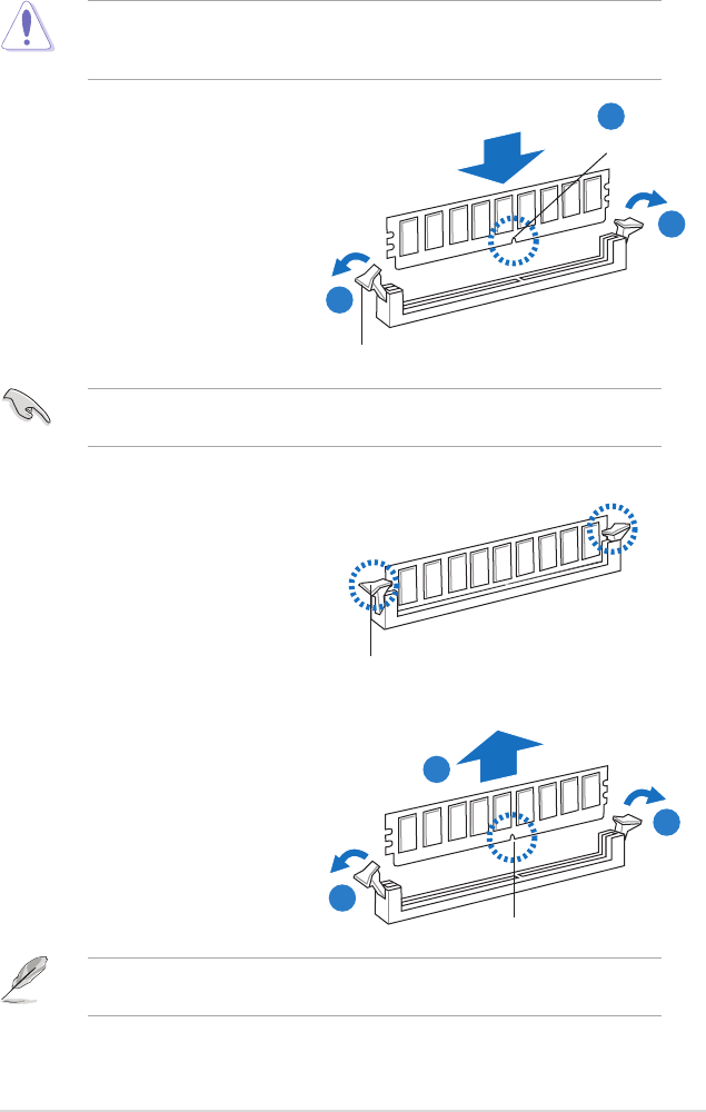
2.4.4 Removing a DIMM
Follow these steps to remove a DIMM.
1. Simultaneously press the
retaining clips outward to unlock
the DIMM.
2. Remove the DIMM from the socket.
Support the DIMM lightly with your ngers when pressing the retaining clips.
The DIMM might get damaged when it ips out with extra force.
2.4.3 Installing a DIMM
DIMM notch
1
1
2
3. Firmly insert the DIMM into the
socket until the retaining clips snap
back in place and the DIMM is
properly seated.
Make sure to unplug the power supply before adding or removing DIMMs or
other system components. Failure to do so may cause severe damage to both
the motherboard and the components.
A DIMM is keyed with a notch so that it ts in only one direction. DO NOT force
a DIMM into a socket to avoid damaging the DIMM.
Unlocked retaining clip
1
DIMM notch
1. Unlock a DIMM socket by
pressing the retaining clips
outward.
2. Align a DIMM on the socket
such that the notch on the DIMM
matches the break on the socket.
Locked Retaining Clip
2
1
ASUS P6T Deluxe V2 2-19

2.5 Expansion slots
In the future, you may need to install expansion cards. The following sub-sections
describe the slots and the expansion cards that they support.
2.5.1 Installing an expansion card
To install an expansion card:
1. Before installing the expansion card, read the documentation that came with
it and make the necessary hardware settings for the card.
2. Remove the system unit cover (if your motherboard is already installed in a
chassis).
3. Remove the bracket opposite the slot that you intend to use. Keep the screw
for later use.
4. Align the card connector with the slot and press rmly until the card is
completely seated on the slot.
5. Secure the card to the chassis with the screw you removed earlier.
6. Replace the system cover.
2.5.2 Conguring an expansion card
After installing the expansion card, congure it by adjusting the software settings.
1. Turn on the system and change the necessary BIOS settings, if any. See
Chapter 3 for information on BIOS setup.
2. Assign an IRQ to the card. Refer to the tables on the next page.
3. Install the software drivers for the expansion card.
Make sure to unplug the power cord before adding or removing expansion
cards. Failure to do so may cause you physical injury and damage motherboard
components.
When using PCI cards on shared slots, ensure that the drivers support “Share
IRQ” or that the cards do not need IRQ assignments. Otherwise, conicts will
arise between the two PCI groups, making the system unstable and the card
inoperable. Refer to the table on the next page for details.
2-20 Chapter 2: Hardware information
2.5.3 Interrupt assignments
Standard interrupt assignments
* These IRQs are usually available for PCI devices.
IRQ Priority Standard function
0 1 System Timer
1 2 Keyboard Controller
2 – Redirect to IRQ#9
4 12 Communications Port (COM1)*
5 13 IRQ Holder for PCI Steering*
6 14 Floppy Disk Controller
7 15 Reserved
8 3 System CMOS/Real Time Clock
9 4 IRQ Holder for PCI Steering*
10 5 IRQ Holder for PCI Steering*
11 6 IRQ Holder for PCI Steering*
12 7 Reserved
13 8 Numeric Data Processor
14 9 Primary IDE Channel
ICH
A B C D E F G H
PCIE16_3 – shared – – – – – –
LAN1 (8056) – – shared – – – – –
LAN2 (8056) – shared – – – – – –
Marvell 6111 shared – – – – – – –
PCI_1 shared – – – – – – –
PCI_2 – shared – – – – – –
USB controller 1 – – – – – – – shared
USB controller 2 – – – shared – – – –
USB controller 3 – – shared – – – – –
USB controller 4 shared – – – – – – –
USB controller 5 – – – – – shared – –
USB controller 6 – – – shared – – – –
USB 2.0 controller 1 – – – – – – – shared
USB 2.0 controller 2 – – shared – – – – –
SATA controller 1 – – – – shared – – –
SATA controller 2 – – – – shared – – –
Audio Azalia – – – – – – shared –
IRQ assignments for this motherboard
IOH
24 25 26 27 28 29 30 31
PCIE4_1 – – – – shared – – –
PCIE16_ shared – – – – – – –
PCIE16_2 – – – – – – shared –
ASUS P6T Deluxe V2 2-21
2.5.4 PCI slots
The PCI slots support cards such as a LAN card, SCSI card, USB card, and other
cards that comply with PCI specications. Refer to the gure below for the location
of the slot.
2.5.5 PCI Express x4 slot
This motherboard supports PCI Express x4 network cards, SCSI cards and other
cards that comply with the PCI Express specications. Refer to the gure below for
the location of the slot.
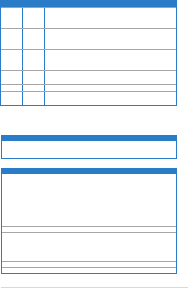
2.5.6 PCI Express 2.0 x16 slots
This motherboard has three PCI Express 2.0 x16 slots that support PCI Express
x16 2.0 graphic cards complying with the PCI Express specications. Refer to the
gure below for the location of the slots.
PCIe 2.0 x16_1 slot (blue, at x16 link)
PCI Express x4_1 slot
PCI slot 1
PCI slot 2
PCIe 2.0 x16_3 slot (black, at max. x8 link)
PCIe 2.0 x16_2 slot (white, at x16 link)
2-22 Chapter 2: Hardware information

• In single VGA card mode, use rst the PCIe 2.0 x16_1 slot (blue) for a PCI
Express x16 graphics card to get better performance.
• In CrossFireX™ or SLI™ mode, use the PCIe 2.0 x16_1 (blue) and PCIe
2.0 x16_2 (white) slots for PCI Express x16 graphics cards to get better
performance.
• Use the three PCIe 2.0 x16 slots for 3-Way CrossFireX™ mode.
• If you install a PCIe x16 graphics card on to the PCIe x16_1 slot, a PCIe
device with a bandwidth faster than x8 link to the PCIe x16_2 slot, and a
PCIe device with a bandwidth slower than x4 link to the PCIe x16_3 slot,
the three PCIe x16 slots will work at x16, x16, x1 link as the default.
• If you install a PCIe x16 graphics card on to the PCIe x16_1 slot, a PCIe
device with a bandwidth slower than x8 link to the PCIe x16_2 slot, and a
PCIe device with a bandwidth faster than x4 link to the PCIe x16_3 slot, the
three PCIe x16 slots will work at x16, x8, x8 link as the default.
• You may manually reassign the link width of PCIe x16_2 and PCIe x16_3
slots in BIOS settings. See page 3-28 for details.
• We recommend that you provide sufcient power when running
CrossFireX™ or SLI™ mode. See page 2-36 for details.
• Connect a chassis fan to the motherboard connector labeled
CHA_FAN1/2/3 when using multiple graphics cards for better thermal
environment. See page 2-34 for details.
VGA conguration PCI Express operating mode
PCIe x16_1 PCIe x16_2 PCIe x16_3
Single VGA/PCIe card x16 (Recommend
for single VGA) x8 (PCIe card) x8 (PCIe card)
Dual VGA/PCIe card x16 x16 x1
Triple VGA/PCIe card x16 x16 x1
x16 x8 x8
ASUS P6T Deluxe V2 2-23
2.6 Jumpers
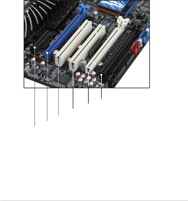
1. Clear RTC RAM (CLRTC)
This jumper allows you to clear the Real Time Clock (RTC) RAM in
CMOS. You can clear the CMOS memory of date, time, and system setup
parameters by erasing the CMOS RTC RAM data. The onboard button
cell battery powers the RAM data in CMOS, which include system setup
information such as system passwords.
Except when clearing the RTC RAM, never remove the cap on CLRTC jumper
default position. Removing the cap will cause system boot failure!
• If the steps above do not help, remove the onboard battery and move
the jumper again to clear the CMOS RTC RAM data. After the CMOS
clearance, reinstall the battery.
• You do not need to clear the RTC when the system hangs due to
overclocking. For system failure due to overclocking, use the C.P.R. (CPU
Parameter Recall) feature. Shut down and reboot the system so the BIOS
can automatically reset parameter settings to default values.
• Due to the chipset behavior, AC power off is required to enable C.P.R.
function. You must turn off and on the power supply or unplug and plug the
power cord before rebooting the system.
To erase the RTC RAM
1. Turn OFF the computer and unplug the power cord.
2. Move the jumper cap from pins 1-2 (default) to pins 2-3. Keep the
cap on pins 2-3 for about 5–10 seconds, then move the cap back
to pins 1-2.
3. Plug the power cord and turn ON the computer.
4. Hold down the <Del> key during the boot process and enter BIOS
setup to re-enter data.
2-24 Chapter 2: Hardware information
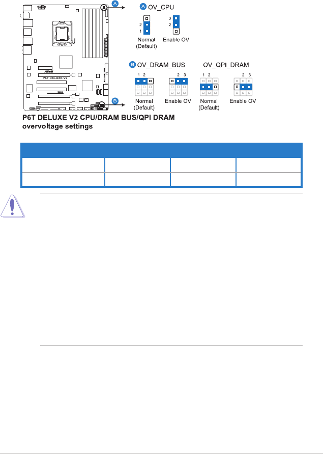
2. CPU / DRAM Bus / QPI DRAM overvoltage setting (3-pin OV_CPU, 3-pin
OV_DRAM_BUS, 3-pin OV_QPI_DRAM)
These jumpers allow you to enable or disable the advanced CPU, DRAM
Bus, and QPI DRAM overvoltage settings in BIOS. Read the following
information before you change the jumper settings.
• Before you change the jumper settings for extra-high overvoltage ability,
use the BIOS items rst to adjust the desired CPU, DRAM, and QPI
performance. Make sure your system functions well under the highest BIOS
voltage settings before you change the setting of these three jumpers.
• DO NOT set the OV_CPU jumper to pins 2–3 when you install a new CPU
and have not booted for the rst time. Doing so may cause the system to
halt. For system failure due to the wrong setting of the OV_CPU jumper,
shut down the computer and move the cap back to pins 1–2.
• According to Intel CPU spec, DIMMs with voltage requirement over 1.65V
may damage the CPU permanently. We recommend you install the DIMMs
with the voltage requirement below 1.65V.
• The system may need a better cooling system (for example, a water-
cooling system) to work stably under high voltage settings.
OV_CPU OV_DRAM_BUS OV_QPI_DRAM
Pins 1-2 (Default) up to 1.70V up to 1.90V up to 1.70V
Pins 2-3 (OV Enabled) up to 2.10V up to 2.46V up to 1.90V
ASUS P6T Deluxe V2 2-25
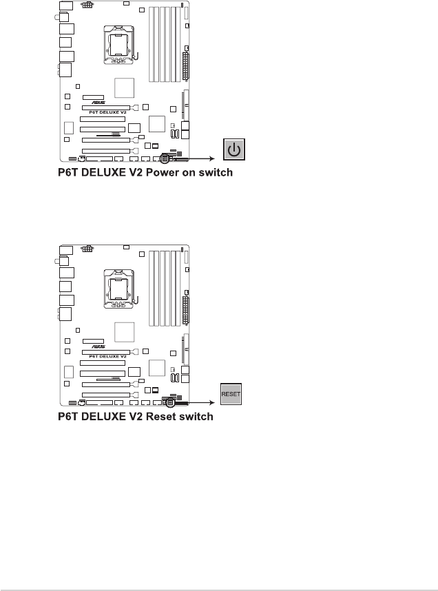
2.7 Onboard switches
Onboard switches allow you to ne-tune performance when working on a bare
or open-case system. This is ideal for overclockers and gamers who continually
change settings to enhance system performance.
1. Power-on switch
Press the power-on switch to wake/power up the system.
2. Reset switch
Press the reset switch to reboot the system.
2-26 Chapter 2: Hardware information
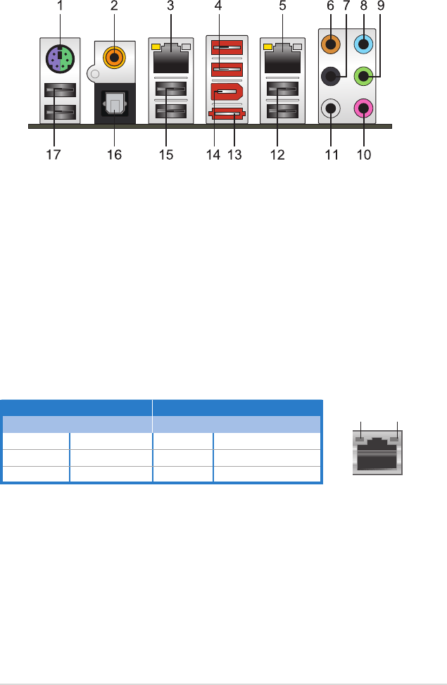
2.8 Connectors
2.8.1 Rear panel connectors
1. PS/2 keyboard / mouse combo port. This port is for a PS/2 keyboard or a
PS/2 mouse.
2. Coaxial S/PDIF Out port. This port connects an external audio output device
via a coaxial S/PDIF cable.
3. LAN 2 (RJ-45) port. This Marvell® LAN port allows Gigabit connection to a
Local Area Network (LAN) through a network hub. Refer to the table below
for the LAN port LED indications.
4. USB 2.0 ports 7 and 8. These 4-pin Universal Serial Bus (USB) ports are
available for connecting USB 2.0 devices.
5. LAN 1 (RJ-45) port. This Marvell® LAN port allows Gigabit connection to a
Local Area Network (LAN) through a network hub. Refer to the table below
for the LAN port LED indications.
Activity Link LED Speed LED
Status Description Status Description
OFF No link OFF 10 Mbps connection
ORANGE Linked ORANGE 100 Mbps connection
BLINKING Data activity GREEN 1 Gbps connection
LAN port LED indications
SPEED
LED
ACT/LINK
LED
LAN port
6. Center/Subwoofer port (orange). This port connects the center/subwoofer
speakers.
7. Rear Speaker Out port (black). This port connects the rear speakers in a
4-channel, 6-channel, or 8-channel audio conguration..
8. Line In port (light blue). This port connects the tape, CD, DVD player, or
other audio sources.
9. Line Out port (lime). This port connects a headphone or a speaker. In
4-channel, 6-channel, and 8-channel conguration, the function of this port
becomes Front Speaker Out.
ASUS P6T Deluxe V2 2-27
12. USB 2.0 ports 1 and 2. These 4-pin Universal Serial Bus (USB) ports are
available for connecting USB 2.0 devices.
13. External SATA port. This port connects to an external a Serial ATA hard disk
drive.
DO NOT insert a different connector to the external SATA port.
14. IEEE 1394a port. This 6-pin IEEE 1394a port provides high-speed
connectivity for audio/video devices, storage peripherals, PCs, or portable
devices.
15. USB 2.0 ports 3 and 4. These 4-pin Universal Serial Bus (USB) ports are
available for connecting USB 2.0 devices.
16. Optical S/PDIF Out port. This port connects an external audio output device
via an optical S/PDIF cable.
17. USB 2.0 ports 5 and 6. These 4-pin Universal Serial Bus (USB) ports are
available for connecting USB 2.0 devices.
Audio 2, 4, 6, or 8-channel conguration
Port Headset
2-channel 4-channel 6-channel 8-channel
Light Blue Line In Line In Line In Line In
Lime Line Out Front Speaker Out Front Speaker Out Front Speaker Out
Pink Mic In Mic In Mic In Mic In
Orange – – Center/Subwoofer Center/Subwoofer
Black – Rear Speaker Out Rear Speaker Out Rear Speaker Out
Gray – – – Side Speaker Out
10. Microphone port (pink). This port connects a microphone.
11. Side Speaker Out port (gray). This port connects the side speakers in an
8-channel audio conguration.
Refer to the audio conguration table below for the function of the audio ports in
2, 4, 6, or 8-channel conguration.
2-28 Chapter 2: Hardware information
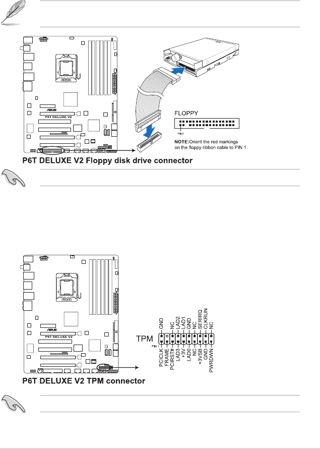
2.8.2 Internal connectors
1. Floppy disk drive connector (34-1 pin FLOPPY)
This connector is for the provided oppy disk drive (FDD) signal cable. Insert
one end of the cable to this connector, then connect the other end to the
signal connector at the back of the oppy disk drive.
Pin 5 on the connector is removed to prevent incorrect cable connection when
using a FDD cable with a covered Pin 5.
2. TPM connector (20-1 pin TPM)
This connector supports a Trusted Platform Module (TPM) system, which can
securely store keys, digital certicates, passwords, and data. A TPM system
also helps enhance network security, protects digital identities, and ensures
platform integrity.
The TPM module is purchased separately.
The oppy cable is purchased separately.
ASUS P6T Deluxe V2 2-29
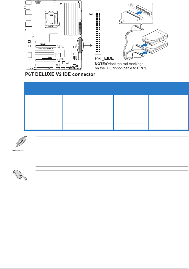
Drive jumper setting Mode of
device(s)
Cable connector
Single device Cable-Select or Master - Black
Two devices Cable-Select Master Black
Slave Gray
Master Master Black or gray
Slave Slave
• Pin 20 on the IDE connector is removed to match the covered hole on the
Ultra DMA cable connector. This prevents incorrect insertion when you
connect the IDE cable.
• Use the 80-conductor IDE cable for Ultra DMA 133/100/66 IDE devices.
If any device jumper is set as “Cable-Select,” make sure all other device
jumpers have the same setting.
3. IDE connector (40-1 pin PRI_EIDE)
The onboard IDE connector is for the Ultra DMA 133/100/66 signal cable.
There are three connectors on each Ultra DMA 133/100/66 signal cable:
blue, black, and gray. Connect the blue connector to the motherboard’s IDE
connector, then select one of the following modes to congure your device.
2-30 Chapter 2: Hardware information
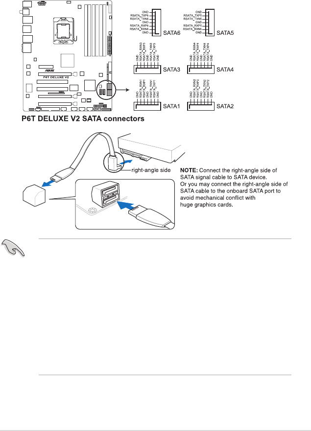
4. ICH10R Serial ATA connectors (7-pin SATA 1-6 [red])
These connectors are for the Serial ATA signal cables for Serial ATA hard disk
drives and optical disc drives.
If you installed Serial ATA hard disk drives, you can create a RAID 0, 1, 5,
and 10 conguration with the Intel® Matrix Storage Technology through the
onboard Intel® ICH10R RAID controller.
•
These connectors are set to Standard IDE mode by default. In Standard
IDE mode, you can connect Serial ATA boot/data hard disk drives to these
connectors. If you intend to create a Serial ATA RAID set using these
connectors, set the Congure SATA as item in the BIOS to [RAID]. See
section 3.3.6 Storage Conguration for details.
• Before creating a RAID set, refer to section 4.4.3 Intel RAID
congurations or the manual bundled in the motherboard support DVD.
•
You must install the Windows® XP Service Pack 1 before using Serial ATA
hard disk drives. The Serial ATA RAID feature (RAID 0, 1, 5, and 10) is
available only if you are using Windows® XP or later version.
•
When using hot-plug and NCQ, set the Congure SATA as in the BIOS to
[AHCI]. See section 3.3.6 Storage Conguration for details.
ASUS P6T Deluxe V2 2-31
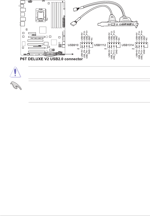
5. USB connectors (10-1 pin USB910, USB1112, USB1314)
These connectors are for USB 2.0 ports. Connect the USB module cable
to any of these connectors, then install the module to a slot opening at the
back of the system chassis. These USB connectors comply with USB 2.0
specication that supports up to 480 Mbps connection speed.
Never connect a 1394 cable to the USB connectors. Doing so will damage the
motherboard!
If your chassis suppots front panel USB ports, you can attach a front panel
USB cable to these connectors. Connect the USB cable to ASUS Q-Connector
(USB, blue) rst, and then install the Q-Connector (USB) to the USB connector
onboard.
2-32 Chapter 2: Hardware information
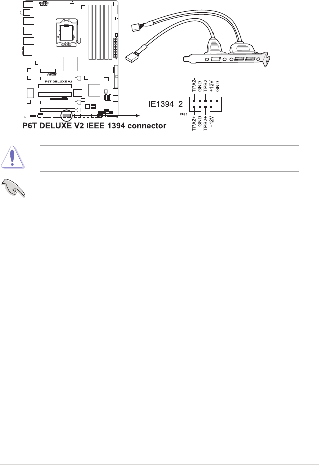
6. IEEE 1394a port connector (10-1 pin IE1394_2)
This connector is for an IEEE 1394a port. Connect the IEEE 1394a module
cable to this connector, then install the module to a slot opening at the back
of the system chassis.
Never connect a USB cable to the IEEE 1394a connector. Doing so will damage
the motherboard!
You can attach a FireWire/1394 cable to this connector if your chassis suppots
the front panel IEEE1394 port.
ASUS P6T Deluxe V2 2-33
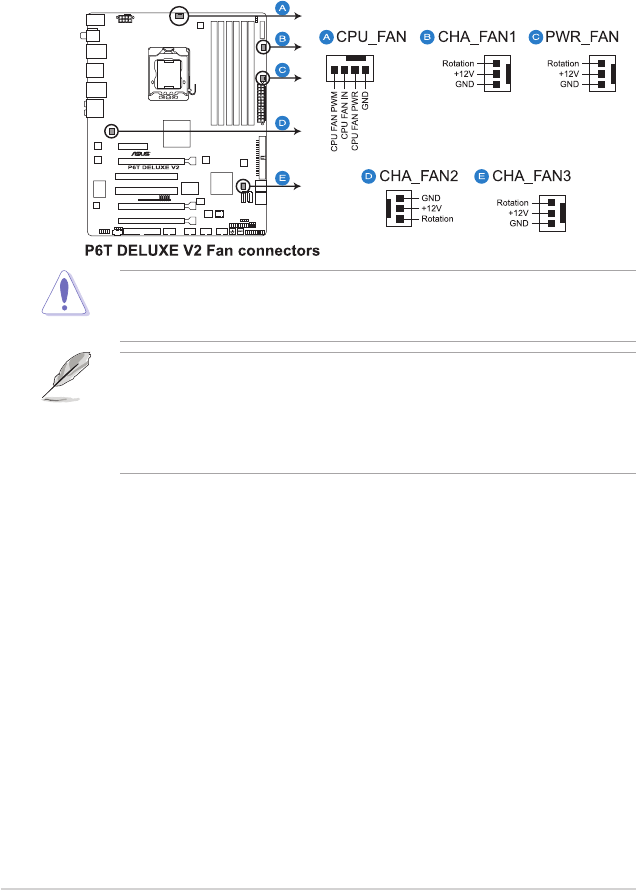
7. CPU, chassis and power fan connectors
(4-pin CPU_FAN, 3-pin CHA_FAN1-3, 3-pin PWR_FAN)
The fan connectors support cooling fans of 350 mA ~ 2000 mA (24 W max.)
or a total of 1 A ~ 7 A (84 W max.) at +12V. Connect the fan cables to the
fan connectors on the motherboard, making sure that the black wire of each
cable matches the ground pin of the connector.
DO NOT forget to connect the fan cables to the fan connectors. Insufcient air
ow inside the system may damage the motherboard components. These are
not jumpers! Do not place jumper caps on the fan connectors!
• Only the CPU-FAN and CHA-FAN 1–3 connectors support the ASUS
Advanced Q-Fan feature.
• If you install two or more VGA cards, we recommend that you plug the
rear chassis fan cable to the motherboard connector labled CHA_FAN2 or
CHA_FAN3 for better thermal environment.
2-34 Chapter 2: Hardware information
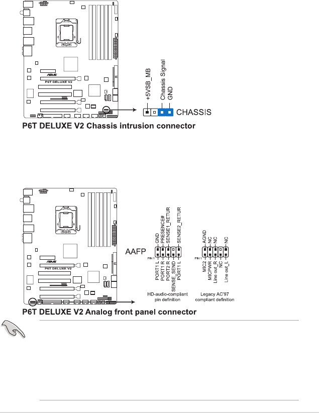
8. Chassis intrusion connector (4-1 pin CHASSIS)
This connector is for a chassis-mounted intrusion detection sensor or switch.
Connect one end of the chassis intrusion sensor or switch cable to this
connector. The chassis intrusion sensor or switch sends a high-level signal to
this connector when a chassis component is removed or replaced. The signal
is then generated as a chassis intrusion event.
By default , the pin labeled “Chassis Signal” and “Ground” are shorted with
a jumper cap. Remove the jumper caps only when you intend to use the
chassis intrusion detection feature.
9. Front panel audio connector (10-1 pin AAFP)
This connector is for a chassis-mounted front panel audio I/O module that
supports either HD Audio or legacy AC`97 audio standard. Connect one end
of the front panel audio I/O module cable to this connector.
• We recommend that you connect a high-denition front panel audio
module to this connector to avail of the motherboard’s high-denition audio
capability.
• If you want to connect a high-denition front panel audio module to this
connector, ensure that the Front Panel Type item in the BIOS is set to [HD
Audio]. If you want to connect an AC' 97 front panel audio module to this
connector, set the item to [AC97]. See page 3-29 or details.
ASUS P6T Deluxe V2 2-35
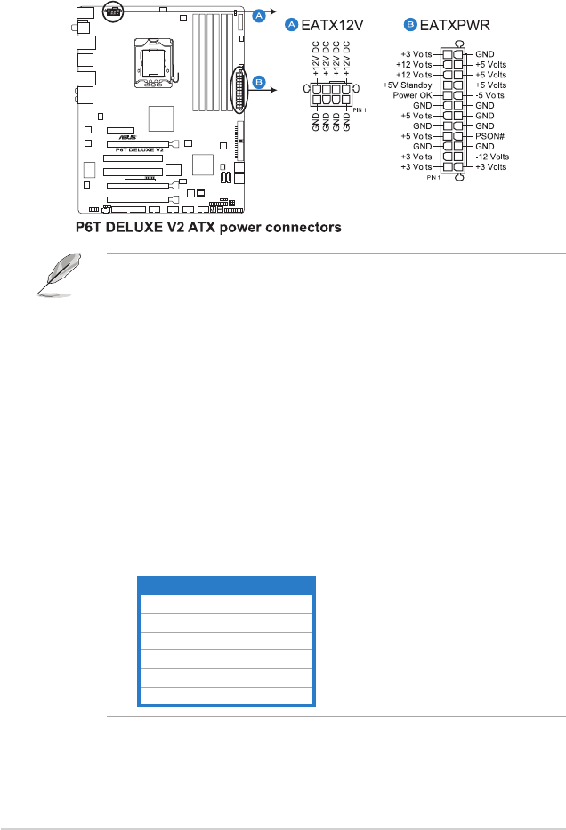
10. ATX power connectors (24-pin EATXPWR, 8-pin EATX12V)
These connectors are for ATX power supply plugs. The power supply plugs
are designed to t these connectors in only one orientation. Find the proper
orientation and push down rmly until the connectors completely t.
• For a fully congured system, we recommend that you use a power supply
unit (PSU) that complies with ATX 12 V Specication 2.0 (or later version)
and provides a minimum power of 600 W.
• Do not forget to connect the 4-pin / 8-pin EATX12 V power plug; otherwise,
the system will not boot.
• Use of a PSU with a higher power output is recommended when
conguring a system with more power-consuming devices. The system
may become unstable or may not boot up if the power is inadequate.
• If you are uncertain about the minimum power supply requirement for your
system, refer to the Recommended Power Supply Wattage Calculator
at http://support.asus.com/PowerSupplyCalculator/PSCalculator.
aspx?SLanguage=en-us for details.
• If you want to use two or more high-end PCI Express x16 cards, use a PSU
with 1000 W power or above to ensure the system stability.
PSU suggested list
PSU suggested list
SilverStone ST1000
Seasonic SS-600HT
Thermaltake W0083RE
Thermaltake PUREPower-600AP
Silverstone SST-ST75ZF
EnerMAX EG701AX-VE (E)(24P)
2-36 Chapter 2: Hardware information
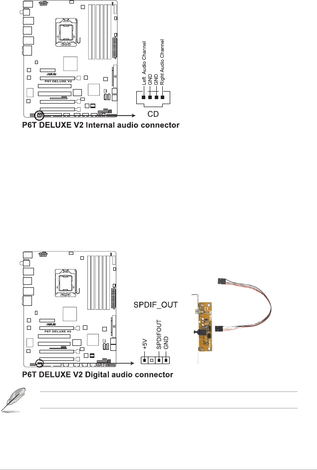
11. Optical drive audio connector (4-pin CD)
This connector allows you to receive stereo audio input from sound sources
such as a CD-ROM, TV tuner, or MPEG card.
12. Digital audio connector (4-1 pin SPDIF)
This connector is for an additional Sony/Philips Digital Interface (S/PDIF)
port(s). If you are using ASUS HDMI-equipped graphics card, connect the
HDMI card to this connector with a S/PDIF out cable.
The S/PDIF out cable are purchased separately.
ASUS P6T Deluxe V2 2-37
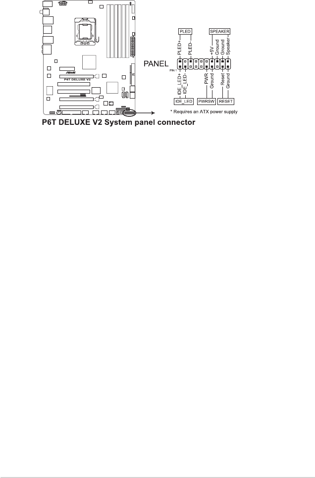
•
System power LED (2-pin PLED)
This 2-pin connector is for the system power LED. Connect the chassis
power LED cable to this connector. The system power LED lights up when
you turn on the system power, and blinks when the system is in sleep mode.
•
Hard disk drive activity LED (2-pin IDE_LED)
This 2-pin connector is for the HDD Activity LED. Connect the HDD Activity
LED cable to this connector. The IDE LED lights up or ashes when data is
read from or written to the HDD.
•
System warning speaker (4-pin SPEAKER)
This 4-pin connector is for the chassis-mounted system warning speaker. The
speaker allows you to hear system beeps and warnings.
•
ATX power button/soft-off button (2-pin PWRSW)
This connector is for the system power button. Pressing the power button
turns the system on or puts the system in sleep or soft-off mode depending
on the BIOS settings. Pressing the power switch for more than four seconds
while the system is ON turns the system OFF.
•
Reset button (2-pin RESET)
This 2-pin connector is for the chassis-mounted reset button for system
reboot without turning off the system power.
13. System panel connector (20-8 pin PANEL)
This connector supports several chassis-mounted functions.
2-38 Chapter 2: Hardware information
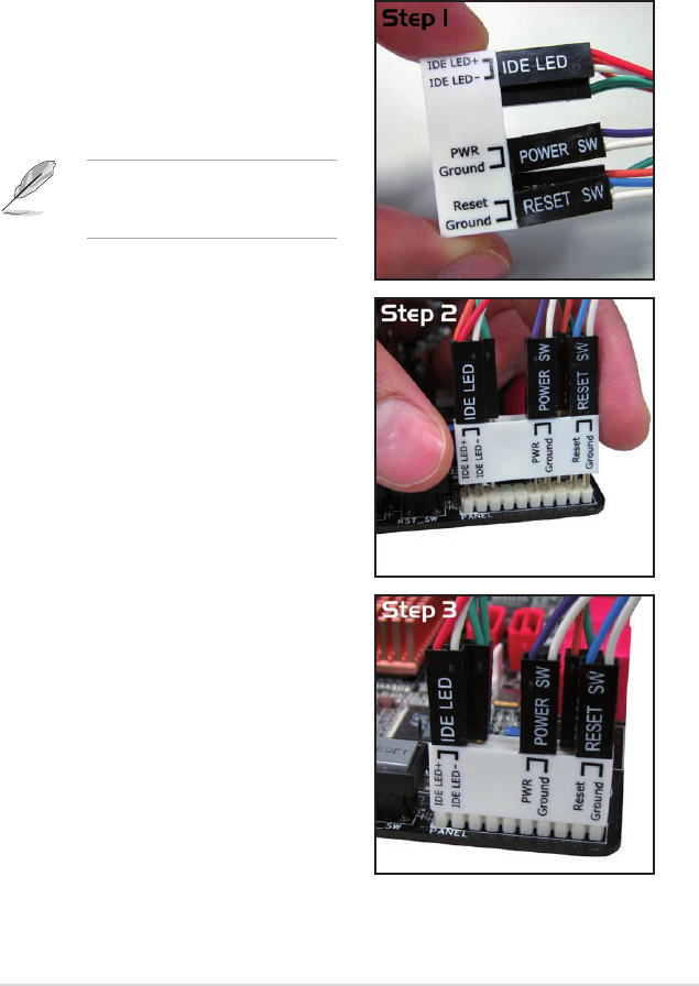
ASUS Q-Connector (system panel)
You can use the ASUS Q-Connector to connect/disconnect chassis front panel
cables in a few steps. Refer to the instructions below to install the ASUS
Q-Connector.
2. Install the ASUS Q-Connector to the
system panel connector, making sure
the orientation matches the labels on the
motherboard.
3. The front panel functions are now
enabled. The gure shows the
Q-Connector properly installed on the
motherboard.
1. Connect the front panel cables to the
ASUS Q-Connector.
Refer to the labels on the Q-Connector
to know the detailed pin denitions, then
match them to the respective front panel
cable labels.
The labels of the front panel
cables may differ from chassis
made by different manufacturers.
ASUS P6T Deluxe V2 2-39
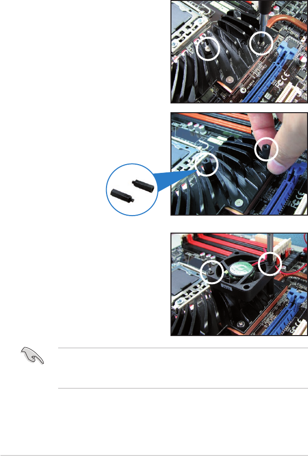
2.9 Installing the additional heatsink fan
You can install an additional 40 mm x 40 mm system fan (purchased separately)
on the Northbridge heatsink for better cooling performance. Follow the instructions
below to install the system fan.
1. Locate the two screws on the
Northbridge heatsink, as shown in
the right gure, and then remove
the two screws from the heatsink.
2. Take out the two bundled screw
pillars from the package, and then
secure the pillars to the Northbridge
heatsink, as shown in the right
gure.
Screw pillars
3. Secure the fan to the screw pillar
with two (2) standard M3 screws
(purchased separately).
• Plug the fan cable to the CHA_FAN3 connector on the motherboard.
• Make sure the fan is installed correctly to prevent damage to the fan and
motherboard components.
2-40 Chapter 2: Hardware information

2.10 Starting up for the rst time
1. After making all the connections, replace the system case cover.
2. Be sure that all switches are off.
3. Connect the power cord to the power connector at the back of the system
chassis.
4. Connect the power cord to a power outlet that is equipped with a surge
protector.
5. Turn on the devices in the following order:
a. Monitor
b. External SCSI devices (starting with the last device on the chain)
c. System power
6. After applying power, the system power LED on the system front panel case
lights up. For systems with ATX power supplies, the system LED lights up
when you press the ATX power button. If your monitor complies with “green”
standards or if it has a “power standby” feature, the monitor LED may light up
or switch between orange and green after the system LED turns on.
The system then runs the power-on self tests or POST. While the tests are
running, the BIOS beeps (see BIOS beep codes table below) or additional
messages appear on the screen. If you do not see anything within 30
seconds from the time you turned on the power, the system may have failed
a power-on test. Check the jumper settings and connections or call your
retailer for assistance.
BIOS Beep Description
One short beep VGA detected
Quick boot set to disabled
No keyboard detected
One continuous beep followed by two
short beeps then a pause (repeated)
No memory detected
One continuous beep followed by three
short beeps
No VGA detected
One continuous beep followed by four
short beeps
Hardware component failure
7. At power on, hold down the <Delete> key to enter the BIOS Setup. Follow the
instructions in Chapter 3.
ASUS P6T Deluxe V2 2-41

2.11 Turning off the computer
2.11.1 Using the OS shut down function
If you are using Windows® Vista™:
1. Click the Start button then select Shut Down.
2. The power supply should turn off after Windows® shuts down.
If you are using Windows® XP:
1. Click the Start button then select Turn Off Computer.
2. Click the Turn Off button to shut down the computer.
3. The power supply should turn off after Windows® shuts down.
2.11.2 Using the dual function power switch
While the system is ON, pressing the power switch for less than four seconds puts
the system to sleep mode or to soft-off mode, depending on the BIOS setting.
Pressing the power switch for more than four seconds lets the system enter the
soft-off mode regardless of the BIOS setting. Refer to section 3.6 Power Menu in
Chapter 3 for details.
2-42 Chapter 2: Hardware information
3
BIOS setup
This chapter tells how to change the
system settings through the BIOS Setup
menus. Detailed descriptions of the
BIOS parameters are also provided.

Chapter summary 3
ASUS P6T Deluxe V2
3.1 Managing and updating your BIOS ............................................ 3-1
3.2 BIOS setup program .................................................................... 3-9
3.3 Main menu .................................................................................. 3-12
3.4 Ai Tweaker .................................................................................. 3-17
3.5 Advanced menu ......................................................................... 3-25
3.6 Power menu ................................................................................ 3-32
3.7 Boot menu .................................................................................. 3-36
3.8 Tools menu ................................................................................. 3-40
3.9 Exit menu .................................................................................... 3-44

ASUS P6T Deluxe V2 3-1
3.1 Managing and updating your BIOS
The following utilities allow you to manage and update the motherboard Basic
Input/Output System (BIOS) setup.
1. ASUS Update (Updates the BIOS in Windows® environment.)
2. ASUS EZ Flash 2 (Updates the BIOS using a oppy disk or USB ash disk.)
3. ASUS AFUDOS (Updates the BIOS using a bootable oppy disk)
4. ASUS CrashFree BIOS 3 (Updates the BIOS using a bootable oppy disk,
USB ash disk or the motherboard support DVD when the BIOS le fails or
gets corrupted.)
Refer to the corresponding sections for details on these utilities.
Save a copy of the original motherboard BIOS le to a bootable oppy disk or
USB ash disk in case you need to restore the BIOS in the future. Copy the
original motherboard BIOS using the ASUS Update or AFUDOS utilities.
Installing ASUS Update
To install ASUS Update:
1. Place the support DVD in the optical drive. The Drivers menu appears.
2. Click the Utilities tab, then click Install ASUS Update VX.XX.XX.
3. The ASUS Update utility is copied to your system.
3.1.1 ASUS Update utility
The ASUS Update is a utility that allows you to manage, save, and update the
motherboard BIOS in Windows® environment. The ASUS Update utility allows you
to:
• Save the current BIOS le
• Download the latest BIOS le from the Internet
• Update the BIOS from an updated BIOS le
• Update the BIOS directly from the Internet, and
• View the BIOS version information.
This utility is available in the support DVD that comes with the motherboard
package.
ASUS Update requires an Internet connection either through a network or an
Internet Service Provider (ISP).
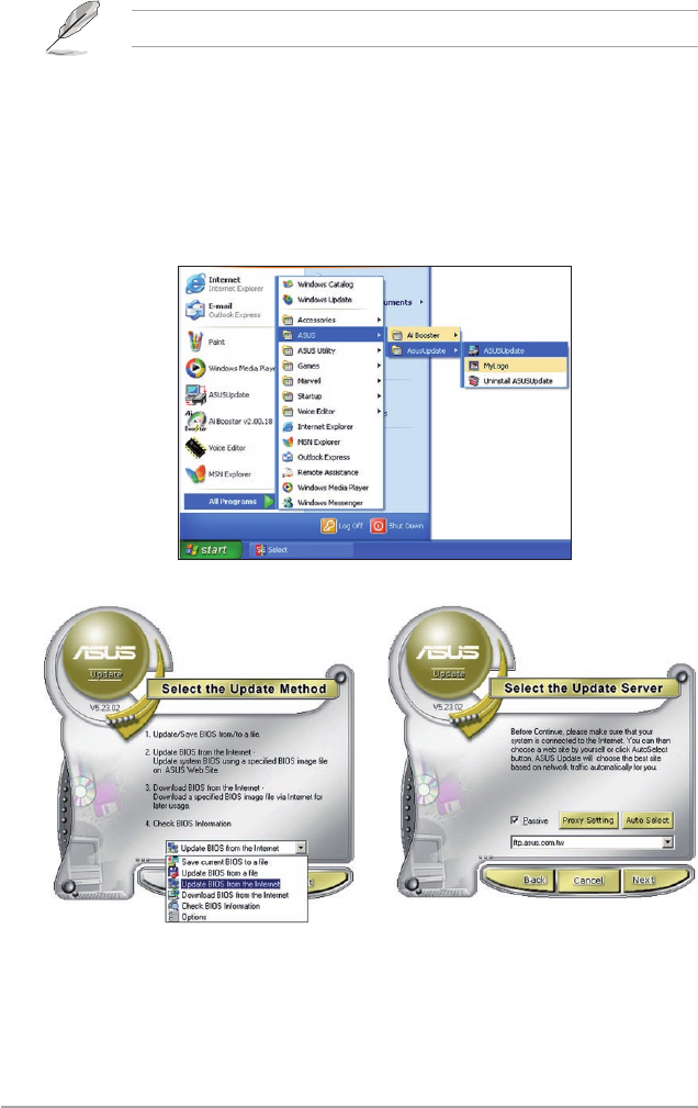
3-2 Chapter 3: BIOS setup
Quit all Windows® applications before you update the BIOS using this utility.
3. Select the ASUS FTP site nearest
you to avoid network trafc, or
click Auto Select. Click Next.
Updating the BIOS through the Internet
To update the BIOS through the Internet:
1. Launch the ASUS Update utility from the Windows® desktop by clicking Start
> Programs > ASUS > ASUSUpdate > ASUSUpdate. The ASUS Update
main window appears.
2. Select Update BIOS from the
Internet option from the drop-down
menu, then click Next.
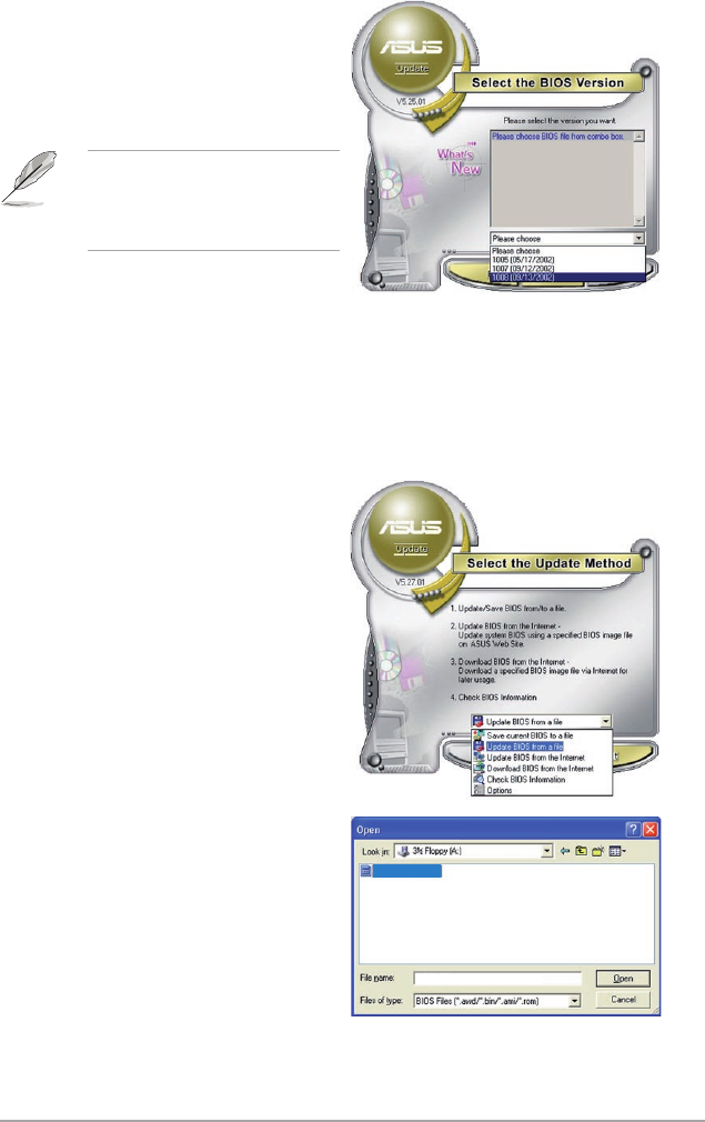
ASUS P6T Deluxe V2 3-3
Updating the BIOS through a BIOS le
To update the BIOS through a BIOS le:
1. Launch the ASUS Update utility from the Windows® desktop by clicking Start
> Programs > ASUS > ASUSUpdate > ASUSUpdate. The ASUS Update
main window appears.
2. Select Update BIOS from a le
option from the drop-down menu,
then click Next.
4. From the FTP site, select the BIOS
version that you wish to download.
Click Next.
5. Follow the screen instructions to
complete the update process.
The ASUS Update utility is
capable of updating itself through
the Internet. Always update the
utility to avail all its features.
3. Locate the BIOS le from the Open
window, then click Open.
4. Follow the screen instructions to
complete the update process.
P6TD
P6TD.ROM
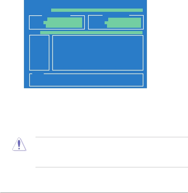
3-4 Chapter 3: BIOS setup
3.1.2 ASUS EZ Flash 2 utility
The ASUS EZ Flash 2 feature allows you to update the BIOS without having to go
through the long process of booting from a oppy disk and using a DOS-based
utility. The EZ Flash 2 utility is built-in the BIOS chip so it is accessible by pressing
<Alt> + <F2> during the Power-On Self Tests (POST).
To update the BIOS using EZ Flash 2
1. Visit the ASUS website (www.asus.com) to download the latest BIOS le for
the motherboard.
2. Save the BIOS le to a oppy disk or a USB ash disk, then restart the
system.
3. You can launch the EZ Flash 2 by two methods.
(1) Insert the oppy disk / USB ash disk that contains the BIOS le to the
oppy disk drive or the USB port.
Press <Alt> + <F2> during POST to display the following.
(2) Enter BIOS setup program. Go to the Tools menu to select EZ Flash2
and press <Enter> to enable it.
You can switch between drives by pressing <Tab> before the correct le
is found. Then press <Enter>.
4. When the correct BIOS le is found, EZ Flash 2 performs the BIOS update
process and automatically reboots the system when done.
• This function can support devices such as a USB ash disk or a oppy disk
with FAT 32/16 format and single partition only.
• DO NOT shut down or reset the system while updating the BIOS to prevent
system boot failure!
ASUSTek EZ Flash 2 BIOS ROM Utility V3.30
Current ROM Update ROM
A:
Note
[Enter] Select or Load [Tab] Switch [V] Drive Info
[Up/Down/Home/End] Move [B] Backup [Esc] Exit
FLASH TYPE: MXIC 25L1605A
PATH: A:\
BOARD: P6T Deluxe V2
VER: 0309
DATE: 09/15/2008
BOARD: Unknown
VER: Unknown
DATE: Unknown

ASUS P6T Deluxe V2 3-5
3.1.3 Creating a bootable oppy disk
1. Do either one of the following to create a bootable oppy disk.
DOS environment
a. Insert a 1.44MB oppy disk into the drive.
b. At the DOS prompt, type
format
A:/S then press <Enter>.
Windows
®
XP environment
a. Insert a 1.44 MB oppy disk to the oppy disk drive.
b. Click Start from the Windows® desktop, then select My Computer.
c. Select the 3 1/2 Floppy Drive icon.
d. Click File from the menu, then select Format. A Format 3 1/2 Floppy
Disk window appears.
e. Select Create an MS-DOS startup disk from the format options eld,
then click Start.
Windows
®
Vista environment
a. Insert a formatted, high density 1.44 MB oppy disk to the oppy disk
drive.
b. Click from the Windows® desktop, then select Computer.
c. Right-click Floppy Disk Drive then click Format to display the Format 3
1/2 Floppy dialog box .
d. Select the Create an MS-DOS startup disk check box.
e. Click Start.
2. Copy the original or the latest motherboard BIOS le to the bootable oppy
disk.

3-6 Chapter 3: BIOS setup
3.1.4 AFUDOS utility
The AFUDOS utility allows you to update the BIOS le in DOS environment using
a bootable oppy disk with the updated BIOS le. This utility also allows you to
copy the current BIOS le that you can use as backup when the BIOS fails or gets
corrupted during the updating process.
Copying the current BIOS
To copy the current BIOS le using the AFUDOS utility
Main lename Extension name
1. Copy the AFUDOS utility (afudos.exe) from the motherboard support DVD to
the bootable oppy disk you created earlier.
2. Boot the system in DOS mode, then at the prompt type:
afudos /o[lename]
where the [lename] is any user-assigned lename not more than eight
alphanumeric characters for the main lename and three alphanumeric
characters for the extension name.
A:\>afudos /oOLDBIOS1.rom
• Make sure that the oppy disk is not write-protected and has at least
1024KB free space to save the le.
• The succeeding BIOS screens are for reference only. The actual BIOS
screen displays may not be same as shown.
The utility returns to the DOS prompt after copying the current BIOS le.
3. Press <Enter>. The utility copies the current BIOS le to the oppy disk.
A:\>afudos /oOLDBIOS1.rom
AMI Firmware Update Utility - Version 1.19(ASUS V2.07(03.11.24BB))
Copyright (C) 2002 American Megatrends, Inc. All rights reserved.
Reading ash ..... done
Write to le...... ok
A:\>
Updating the BIOS le
To update the BIOS le using the AFUDOS utility:
1. Visit the ASUS website (www.asus.com) and download the latest BIOS le for
the motherboard. Save the BIOS le to a bootable oppy disk.
ASUS P6T Deluxe V2 3-7
2. Copy the AFUDOS utility (afudos.exe) from the motherboard support DVD to
the bootable oppy disk you created earlier.
3. Boot the system in DOS mode, then at the prompt type:
afudos /i[lename]
where [lename] is the latest or the original BIOS le on the bootable oppy
disk.
A:\>afudos /iP6TD.ROM
Write the BIOS lename on a piece of paper. You need to type the exact BIOS
lename at the DOS prompt.
5. The utility returns to the DOS prompt after the BIOS update process is
completed. Reboot the system from the hard disk drive.
A:\>afudos /iP6TD.ROM
AMI Firmware Update Utility - Version 1.19(ASUS V2.07(03.11.24BB))
Copyright (C) 2002 American Megatrends, Inc. All rights reserved.
WARNING!! Do not turn off power during ash BIOS
Reading le ....... done
Reading ash ...... done
Advance Check ......
Erasing ash ...... done
Writing ash ...... done
Verifying ash .... done
Please restart your computer
A:\>
A:\>afudos /iP6TD.ROM
AMI Firmware Update Utility - Version 1.19(ASUS V2.07(03.11.24BB))
Copyright (C) 2002 American Megatrends, Inc. All rights reserved.
WARNING!! Do not turn off power during ash BIOS
Reading le ....... done
Reading ash ...... done
Advance Check ......
Erasing ash ...... done
Writing ash ...... 0x0008CC00 (9%)
4. The utility veries the le and starts updating the BIOS.
DO NOT shut down or reset the system while updating the BIOS to prevent
system boot failure!

3-8 Chapter 3: BIOS setup
3.1.5 ASUS CrashFree BIOS 3 utility
The ASUS CrashFree BIOS 3 is an auto recovery tool that allows you to restore
the BIOS le when it fails or gets corrupted during the updating process. You can
update a corrupted BIOS le using the motherboard support DVD, the oppy disk,
or the USB ash disk that contains the updated BIOS le.
Prepare the motherboard support DVD, the oppy disk or the USB ash disk
containing the updated motherboard BIOS before using this utility.
Recovering the BIOS from the support DVD
To recover the BIOS from the support DVD:
1. Turn on the system.
2. Insert the motherboard support DVD to the optical drive.
3. The utility displays the following message and automatically checks the DVD
for the BIOS le.
4. Restart the system after the utility completes the updating process.
• Only the USB ash disk with FAT 32/16 format and single partition can
support ASUS CrashFree BIOS 3. The device size should be smaller than
8GB.
• DO NOT shut down or reset the system while updating the BIOS! Doing so
can cause system boot failure!
When found, the utility reads the BIOS le and starts ashing the corrupted
BIOS le.
Recovering the BIOS from the oppy disk or USB ash disk
To recover the BIOS from the oppy disk or USB ash disk:
1. Insert the oppy disk or USB ash disk that contains BIOS le to the oppy
disk drive or USB port.
2. Turn on the system.
3. The utility will automatically checks the devices for the BIOS le When found,
the utility reads the BIOS le and starts ashing the corrupted BIOS le.
4. Restart the system after the utility completes the updating process.
Bad BIOS checksum. Starting BIOS recovery...
Checking for oppy...
Bad BIOS checksum. Starting BIOS recovery...
Checking for oppy...
Floppy found!
Reading le “P6TD.ROM”. Completed.
Start ashing...

ASUS P6T Deluxe V2 3-9
3.2 BIOS setup program
This motherboard supports a programmable rmware chip that you can update
using the provided utility described in section 3.1 Managing and updating your
BIOS.
Use the BIOS Setup program when you are installing a motherboard, reconguring
your system, or prompted to “Run Setup.” This section explains how to congure
your system using this utility.
Even if you are not prompted to use the Setup program, you can change the
conguration of your computer in the future. For example, you can enable the
security password feature or change the power management settings. This
requires you to recongure your system using the BIOS Setup program so that the
computer can recognize these changes and record them in the CMOS RAM of the
rmware chip.
The rmware chip on the motherboard stores the Setup utility. When you start up
the computer, the system provides you with the opportunity to run this program.
Press <Del> during the Power-On Self-Test (POST) to enter the Setup utility;
otherwise, POST continues with its test routines.
If you wish to enter Setup after POST, restart the system by pressing
<Ctrl+Alt+Delete>, or by pressing the reset button on the system chassis. You can
also restart by turning the system off and then back on. Do this last option only if
the rst two failed.
The Setup program is designed to make it as easy to use as possible. Being a
menu-driven program, it lets you scroll through the various sub-menus and make
your selections from the available options using the navigation keys.
• The default BIOS settings for this motherboard apply for most conditions
to ensure optimum performance. If the system becomes unstable after
changing any BIOS settings, load the default settings to ensure system
compatibility and stability. Select the Load Setup Defaults item under the
Exit Menu. See section 3.9 Exit Menu.
• The BIOS setup screens shown in this section are for reference purposes
only, and may not exactly match what you see on your screen.
• Visit the ASUS website (www.asus.com) to download the latest BIOS le for
this motherboard.
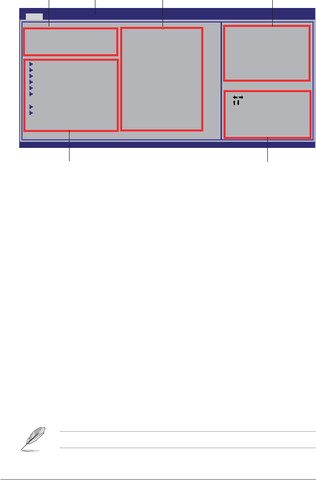
3-10 Chapter 3: BIOS setup
3.2.2 Menu bar
The menu bar on top of the screen has the following main items:
Main For changing the basic system conguration
Ai Tweaker For changing the overclocking settings
Advanced For changing the advanced system settings
Power For changing the advanced power management (APM)
conguration
Boot For changing the system boot conguration
Tools For conguring options for special functions
Exit For selecting the exit options and loading default
settings
To select an item on the menu bar, press the right or left arrow key on the keyboard
until the desired item is highlighted.
3.2.3 Navigation keys
At the bottom right corner of a menu screen are the navigation keys for that
particular menu. Use the navigation keys to select items in the menu and change
the settings.
3.2.1 BIOS menu screen
The navigation keys may differ from one screen to another.
Select Screen
Select Item
+- Change Field
Tab Select Field
F1 General Help
F10 Save and Exit
ESC Exit
v02.61 (C)Copyright 1985-2008, American Megatrends, Inc.
BIOS SETUP UTILITY
Main Ai Tweaker Advanced Power Boot Tools Exit
System Time [13:51:25]
System Date [Tue 09/16/2008]
Legacy Diskette A [1.44M, 3.5 in.]
Language [English]
SATA1 [HDT722516DLA380]
SATA2 [Not Detected]
SATA3 [ATAPI DVD DH1]
SATA4 [Not Detected]
SATA5 [Not Detected]
SATA6 [Not Detected]
Storage Conguration
System InformationSystem Information
Use [ENTER], [TAB]
or [SHIFT-TAB] to
select a eld.
Use [+] or [-]
to congure the
System Time.
Navigation keys
General help
Menu bar
Sub-menu items
Conguration eldsMenu items
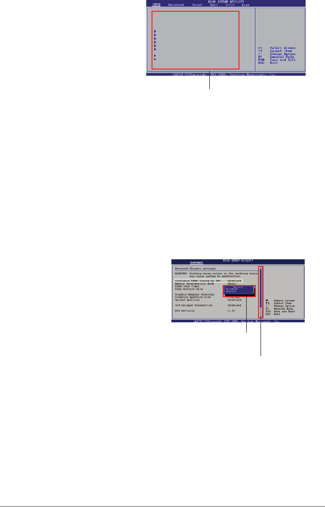
ASUS P6T Deluxe V2 3-11
3.2.4 Menu items
The highlighted item on the menu bar
displays the specic items for that
menu. For example, selecting Main
shows the Main menu items.
The other items (Advanced, Power,
Boot, and Exit) on the menu bar have
their respective menu items.
3.2.5 Sub-menu items
A solid triangle before each item on any menu screen means that the iteam has a
sub-menu. To display the sub-menu, select the item and press <Enter>.
3.2.6 Conguration elds
These elds show the values for the menu items. If an item is user- congurable,
you can change the value of the eld opposite the item. You cannot select an item
that is not user-congurable.
A congurable eld is enclosed in brackets, and is highlighted when selected. To
change the value of a eld, select it then press <Enter> to display a list of options.
Refer to 3.2.7 Pop-up window.
3.2.7 Pop-up window
Select a menu item then press <Enter>
to display a pop-up window with the
conguration options for that item.
3.2.8 Scroll bar
A scroll bar appears on the right side of a
menu screen when there are items that do
not t on the screen. Press the
Up/Down arrow keys or <Page Up> /<Page
Down> keys to display the other items on
the screen.
3.2.9 General help
At the top right corner of the menu screen is a brief description of the selected
item.
Scroll bar
Pop-up window
Main menu items
System Time [11:56:54]
System Date [Mon 08/04/2008]
Floppy Diskette A [1.44M, 3.5 in.]
Language [English]
SATA1 [Not Detected]
SATA2 [Not Detected]
SATA3 [Not Detected]
SATA4 [Not Detected]
SATA5 [Not Detected]
SATA6 [Not Detected]
IDE Conguration
System Information
Use [ENTER], [TAB], or
[SHIFT-TAB] to select
a eld.
Use [+] or [-] to
congure system Time.
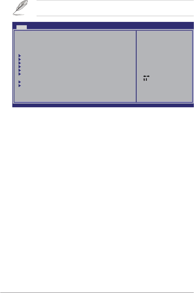
3-12 Chapter 3: BIOS setup
3.3 Main menu
When you enter the BIOS Setup program, the Main menu screen appears, giving
you an overview of the basic system information.
3.3.1 System Time [xx:xx:xx]
Allows you to set the system time.
3.3.2 System Date [Day xx/xx/xxxx]
Allows you to set the system date.
3.3.3 Legacy Diskette A [1.44M, 3.5 in.]
Sets the type of oppy drive installed.
Conguration options: [Disabled] [720K , 3.5 in.] [1.44M, 3.5 in.]
3.3.4 Language [English]
Allows you to select the display language for the BIOS setup screen.
Conguration options: [Chinese(BIG5)] [Chinese(GB)] [Japanese] [French]
[German] [English]
Refer to section 3.2.1 BIOS menu screen for information on the menu screen
items and how to navigate through them.
Select Screen
Select Item
+- Change Field
Tab Select Field
F1 General Help
F10 Save and Exit
ESC Exit
v02.61 (C)Copyright 1985-2008, American Megatrends, Inc.
BIOS SETUP UTILITY
Main Ai Tweaker Advanced Power Boot Tools Exit
System Time [11:55:25]
System Date [Tue 09/16/2008]
Legacy Diskette A [1.44M, 3.5 in.]
Language [English]
SATA1 [HDT722516DLA380]
SATA2 [Not Detected]
SATA3 [ATAPI DVD DH1]
SATA4 [Not Detected]
SATA5 [Not Detected]
SATA6 [Not Detected]
Storage Conguration
System InformationSystem Information
Use [ENTER], [TAB]
or [SHIFT-TAB] to
select a eld.
Use [+] or [-] to
congure System Time.

ASUS P6T Deluxe V2 3-13
3.3.5 SATA 1-6
While entering Setup, the BIOS automatically detects the presence of Serial ATA
devices. There is a separate sub-menu for each SATA device. Select a device item
then press <Enter> to display the SATA device information.
Select Screen
Select Item
+- Change Option
F1 General Help
F10 Save and Exit
ESC Exit
v02.61 (C)Copyright 1985-2008, American Megatrends, Inc.
BIOS SETUP UTILITY
Main
SATA 1
Device : Hard Disk
Vendor : HDT722516DLA380
Size : 164.7GB
LBA Mode : Supported
Block Mode : 16Sectors
PIO Mode : 4
Async DMA : MultiWord DMA-2
Ultra DMA : Ultra DMA-5
SMART Monitoring: Supported
Type [Auto]
LBA/Large Mode [Auto]
Block(Multi-Sector Transfer)M [Auto]
PIO Mode [Auto]
DMA Mode [Auto]
SMART Monitoring [Auto]
32Bit Data Transfer [Enabled]
Select the type of
device connected to
the system.
The BIOS automatically detects the values opposite the dimmed items (Device,
Vendor, Size, LBA Mode, Block Mode, PIO Mode, Async DMA, Ultra DMA, and
SMART monitoring). These values are not user-congurable. These items show
N/A if no SATA device is installed in the system.
Type [Auto]
Selects the type of drive connected to the system. Setting to [Auto] allows
automatic selection of the appropriate IDE device type. Select [CDROM] if you are
specically conguring a CD-ROM drive. Select [ARMD] (ATAPI Removable Media
Device) if your device is either a ZIP, LS-120, or MO drive.
Conguration options: [Not Installed] [Auto] [CDROM] [ARMD]
LBA/Large Mode [Auto]
Enables or disables the LBA mode. Setting to [Auto] enables the LBA mode if the
device supports this mode, and if the device was not previously formatted with LBA
mode disabled.
Conguration options: [Disabled] [Auto]
Block (Multi-Sector Transfer) M [Auto]
Enables or disables data multi-sectors transfers. When set to [Auto], the data
transfer from and to the device occurs multiple sectors at a time if the device
supports multi-sector transfer feature. When set to [Disabled], the data transfer
from and to the device occurs one sector at a time.
Conguration options: [Disabled] [Auto]
PIO Mode [Auto]
Allows you to select the data transfer mode.
Conguration options: [Auto] [0] [1] [2] [3] [4]
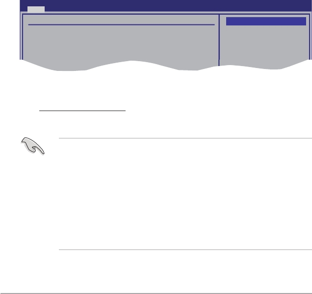
3-14 Chapter 3: BIOS setup
DMA Mode [Auto]
Selects the DMA mode.
Conguration options: [Auto] [SWDMA0] [SWDMA1] [SWDMA2] [MWDMA0]
[MWDMA1] [MWDMA2] [UDMA0] [UDMA1] [UDMA2] [UDMA3] [UDMA4] [UDMA5]
SMART Monitoring [Auto]
Sets the Self-Monitoring, Analysis, and Reporting Technology.
Conguration options: [Auto] [Disabled] [Enabled]
32Bit Data Transfer [Enabled]
Enables or disables 32-bit data transfer.
Conguration options: [Disabled] [Enabled]
3.3.6 Storage Conguration
The items in this menu allow you to set or change the congurations for the SATA
devices installed in the system. Select an item then press <Enter> if you want to
congure the item.
Storage Conguration
SATA Conguraton [Enhanced]
Congure SATA as [IDE]
Hard Disk Write Protect [Disabled]
IDE Detect Time Out (Sec) [35]
Options
Disabled
Compatible
Enhanced
BIOS SETUP UTILITY
Main
SATA Conguration [Enhanced]
Conguration options: [Disabled] [Compatible] [Enhanced]
Configure SATA as [IDE]
Sets the conguration for the Serial ATA connectors supported by the
Southbridge chip. Conguration options: [IDE] [RAID] [AHCI]
• If you want to use the Serial ATA hard disk drives as Parallel ATA physical
storage devices, keep the default setting [IDE].
• If you want the Serial ATA hard disk drives to use the Advanced Host
Controller Interface (AHCI), set this item to [AHCI]. The AHCI allows
the onboard storage driver to enable advanced Serial ATA features that
increases storage performance on random workloads by allowing the drive
to internally optimize the order of commands.
• If you want to create a RAID 0, RAID 1, RAID 5, RAID 10, or the Intel®
Matrix Storage Technology conguration from the Serial ATA hard disk
drives, set this item to [RAID].
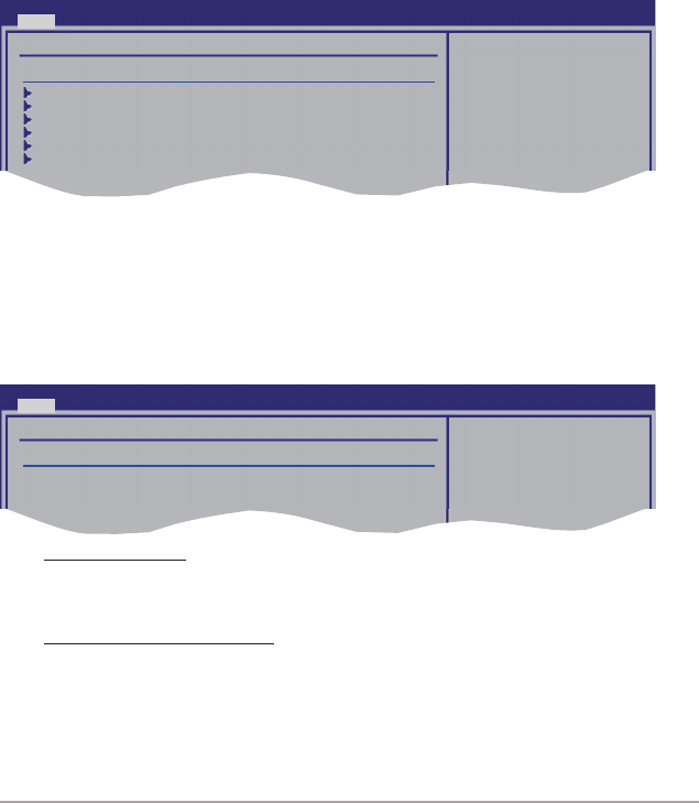
ASUS P6T Deluxe V2 3-15
Hard Disk Write Protect [Disabled]
Disables or enables device write protection. This will be effective only if the device
is accessed through BIOS.
Conguration option: [Disabled] [Enabled]
IDE Detect Time Out (Sec) [35]
Selects the time out value for detecting ATA/ATAPI devices.
Conguration options: [0] [5] [10] [15] [20] [25] [30] [35]
SATA Port1 [Auto]
Allows you to select the type of device connected to the system.
Conguration options: [Auto] [Not Installed]
SMART Monitoring [Enabled]
Allows you to set the Self-Monitoring, Analysis and Reporting Technology.
Congration options: [Disabled] [Enabled]
3.3.7 AHCI Conguration
This menu is the section for AHCI conguration. It appears only when you set the
item Congure SATA as from the sub-menu of SATA Conguration to [AHCI].
AHCI CD/DVD Boot Time out [35]
Selects the boot time out value for SATA CD/DVD devices in AHCI mode.
Congifuration options: [0] [5] [10] [15] [20] [25] [30] [35]
AHCI Port1–6 [XXXX]
Displays the status of auto-detection of SATA devices.
Some SATA CD/DVD in
AHCI mode need to
wait ready longer.
AHCI Settings
AHCI CD/DVD Boot Time out [35]
SATA Port1 [Not Detected]
SATA Port2 [Not Detected]
SATA Port3 [Not Detected]
SATA Port4 [Not Detected]
SATA Port5 [Not Detected]
SATA Port6 [Not Detected]
BIOS SETUP UTILITY
Main
BIOS SETUP UTILITY
Main
AHCI Port1
Device :Not Detected
SATA Port1 [Auto]
SMART Monitoring [Enabled]
Select the type
of devices connected
to the system.

3-16 Chapter 3: BIOS setup
3.3.8 System Information
This menu gives you an overview of the general system specications. The BIOS
automatically detects the items in this menu.
Bios Information
Displays the auto-detected BIOS information.
Processor
Displays the auto-detected CPU specication.
System Memory
Displays the auto-detected system memory.
Select Screen
Select Item
F1 General Help
F10 Save and Exit
ESC Exit
v02.61 (C)Copyright 1985-2008, American Megatrends, Inc.
BIOS SETUP UTILITY
Main
Bios Information
Version : 0309
Build Date : 09/15/08
Processor
Type : Genuine Intel(R) CPU @ 2.67GHz
Speed : 2689MHz
System Memory
Usable Size : 1016MB
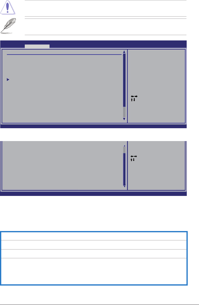
ASUS P6T Deluxe V2 3-17
3.4 Ai Tweaker menu
The Ai Tweaker menu items allow you to congure overclocking-related items.
Take caution when changing the settings of the Ai Tweaker menu items.
Incorrect eld values can cause the system to malfunction.
The default values of the following items vary depending on the CPU and
memory modules you install on the motherboard.
Select Screen
Select Item
Enter Go to Sub Screen
+- Change Option
F1 General Help
F10 Save and Exit
ESC Exit
v02.61 (C)Copyright 1985-2008, American Megatrends, Inc.
BIOS SETUP UTILITY
Main Ai Tweaker Advanced Power Boot Tools Exit
Congure System Performance Settings
Ai Overclock Tuner [Auto]
CPU Ratio Setting [Auto]
Intel(R) SpeedStep(TM) Tech [Enabled]
Intel(R) Turbo Mode Tech [Enabled]
DRAM Frequency [Auto]
DRAM Timing Control
******* Please key in numbers directly! *******
CPU Voltage [Auto]
CPU PLL Voltage [Auto]
QPI/DRAM Core Voltage [Auto]
IOH Voltage [Auto]
IOH PCIE Voltage [Auto]
ICH Voltage [Auto]
ICH PCIE Voltage [Auto]
DRAM Bus Voltage [Auto]
DRAM DATA REF Voltage on CHA [Auto]
[D.O.C.P]
It’s designed to
overclock DRAM
frequency by adjusting
BCLK frequency.
[X.M.P.]
When X.M.P. is enabled
BLCK frequency,
CPU ratio and memory
parameters will be
auto optimized.
Scroll down to display the following items:
v02.61 (C)Copyright 1985-2008, American Megatrends, Inc.
DRAM CTRL REF Voltage on CHA [Auto]
DRAM DATA REF Voltage on CHB [Auto]
DRAM CTRL REF Voltage on CHB [Auto]
DRAM DATA REF Voltage on CHC [Auto]
DRAM CTRL REF Voltage on CHC [Auto]
***********************************************
Load-Line Calibration [Auto]
CPU Differential Amplitude [Auto]
CPU Clock Skew [Auto]
CPU Spread Spectrum [Auto]
IOH Clock Skew [Auto]
PCIE Spread Spectrum [Auto]
Select Screen
Select Item
Enter Go to Sub Screen
+- Change Option
F1 General Help
F10 Save and Exit
ESC Exit
3.4.1 Ai Overclock Tuner [Auto]
Allows selection of CPU overclocking options to achieve desired CPU internal
frequency. Select either one of the preset overclocking conguration options:
Manual Allows you to individually set overclocking parameters.
Auto Loads the optimal settings for the system.
D.O.C.P Overclocks DRAM frequency by adjusting BCLK frequency.
X.M.P. If you install memory module(s) supporting the eXtreme
Memory Prole (X.M.P.) Technology, choose this item to set the
prole(s) supported by your memory module(s) for optimizing
the system performance.

3-18 Chapter 3: BIOS setup
3.4.2 CPU Ratio Setting [Auto]
Allows you to adjust the ratio between CPU Core Clock and BCLK Frequency. Use
the <+> and <-> keys to adjust the value.
Conguration options: [Auto] [12.0] [13.0] [14.0] [15.0] [16.0] [17.0] [18.0] [19.0]
[20.0]
3.4.3 Intel(R) SpeedStep(TM) Tech [Enabled]
When set to [Disabled], the CPU runs at its default speed. When set to [Enabled],
the CPU speed is controlled by the operating system.
Conguration options: [Disabled] [Enabled]
3.4.4 Intel(R) Turbo Mode Tech [Enabled]
Turbo mode allows processor cores to run faster than marked frequency in specic
condition.
Conguration options: [Disabled] [Enabled]
The following two items appear only when you set the Ai Overclock Tuner item
to [Manual], [D.O.C.P.] or [X.M.P.].
BCLK Frequency [XXX]
Allows you to adjust the Internal Base Clock (BCLK). Use the <+> and <-> keys to
adjust the value. You can also type the desired value using the numeric keypad.
The values range from 100 to 500.
DRAM O.C. Profile [DDR3-1339MHz]
This item appears only when you set the Ai Overclock Tuner item to
[D.O.C.P.] and allows you to select a DRAM O.C. prole, which applies
different settings to DRAM frequency, DRAM timing and DRAM voltage.
Conguration options: [DDR3-1339MHz] [DDR3-1603MHz]
eXtreme Memory Profile [High Performance]
This item appears only when you set the Ai Overclock Tuner item to [X.M.P.]
and allows you to select the X.M.P. mode supported by your memory module.
Conguration options: [High Performance] [High Frequency]
The conguration options for the following sub-item vary depending on the
DIMMs you install on the motherboard.
To obtain the best performance of the X.M.P. DIMM or 1600MHz DIMM, install
only one DIMM on each memory channel.
ASUS P6T Deluxe V2 3-19
PCIE Frequency [XXX]
Allows you to set the PCI Express frequency. Use the <+> and <-> keys to adjust
the PCIE frequency. The values range from 100 to 200.
3.4.5 DRAM Frequency [Auto]
Allows you to set the DDR3 operating frequency.
Conguration options: [Auto] [DDR3-800MHz] [DDR3-1066MHz]
The DRAM Frequency conguration options vary with the BCLK Frequency
item settings.
Selecting a very high DRAM frequency may cause the system to become
unstable! If this happens, revert to the default setting.
3.4.6. DRAM Timing Control [Auto]
The items in this menu allow you to set the DRAM timing control features.
The conguration options for some of the following items vary depending on thedepending on the
DIMMs you install on the motherboard.
1st Information: 6-6-6-15-4-36-6-3-16-4
The values vary depending on your settings of the following sub-items:
DRAM CAS# Latency [Auto]
Conguration options: [Auto] [3 DRAM Clock] [4 DRAM Clock] – [10 DRAM
Clock] [11 DRAM Clock]
DRAM RAS# to CAS# Delay [Auto]
Conguration options: [Auto] [3 DRAM Clock] [4 DRAM Clock] – [9 DRAM
Clock] [10 DRAM Clock]
DRAM RAS# PRE Time [Auto]
Conguration options: [Auto] [3 DRAM Clock] [4 DRAM Clock] – [9 DRAM
Clock] [10 DRAM Clock]
DRAM RAS# ACT Time [Auto]
Conguration options: [Auto] [3 DRAM Clock] [4 DRAM Clock] – [32 DRAM
Clock] [33 DRAM Clock]
DRAM RAS# to RAS# Delay [Auto]
Conguration options: [Auto] [1 DRAM Clock] – [15 DRAM Clock]
DRAM REF Cycle Time [Auto]
Conguration options: [Auto] [30 DRAM Clock] [36 DRAM Clock]
[48 DRAM Clock] [60 DRAM Clock] [72 DRAM Clock] [82 DRAM Clock]
[88 DRAM Clock] [90 DRAM Clock] [100 DRAM Clock] [110 DRAM Clock]

3-20 Chapter 3: BIOS setup
DRAM WRITE Recovery Time [Auto]
Conguration options: [Auto] [1 DRAM Clock] – [15 DRAM Clock]
DRAM READ to PRE Time [Auto]
Conguration options: [Auto] [1 DRAM Clock] – [15 DRAM Clock]
DRAM FOUR ACT WIN Time [Auto]
Conguration options: [Auto] [1 DRAM Clock] – [31 DRAM Clock]
DRAM WRITE to READ Delay [Auto]
Conguration options: [Auto] [1 DRAM Clock] – [15 DRAM Clock]
2nd Information: 1N-52-0-0
The values vary depending on your settings of the following sub-items:
DRAM Timing Mode [Auto]
Conguration options: [Auto] [1N] [2N] [3N]
DRAM Round Trip Latency on CHA [Auto]
[Auto] [Advance 15 Clock]–[Advance 1 Clock] [Normal] [Delay 1 Clock]
[Delay 15 Clock]
DRAM Round Trip Latency on CHB [Auto]
[Auto] [Advance 15 Clock]–[Advance 1 Clock] [Normal] [Delay 1 Clock]
[Delay 15 Clock]
DRAM Round Trip Latency on CHC [Auto]
[Auto] [Advance 15 Clock]–[Advance 1 Clock] [Normal] [Delay 1 Clock]
[Delay 15 Clock]
3rd Information: 6-6-13-9-9-9-7-6-4-7-7-4
The values vary depending on your settings of the following sub-items:
DRAM WRITE to READ Delay(DD) [Auto]
Conguration options: [Auto] [1 DRAM Clock] – [8 DRAM Clock]
DRAM WRITE to READ Delay(DR) [Auto]
Conguration options: [Auto] [1 DRAM Clock] – [8 DRAM Clock]
DRAM WRITE to READ Delay(SR) [Auto]
Conguration options: [Auto] [10 DRAM Clock] – [25 DRAM Clock]
DRAM READ to WRITE Delay(DD) [Auto]
Conguration options: [Auto] [2 DRAM Clock] – [14 DRAM Clock]
DRAM READ to WRITE Delay(DR) [Auto]
Conguration options: [Auto] [2 DRAM Clock] – [14 DRAM Clock]
DRAM READ to WRITE Delay(SR) [Auto]
Conguration options: [Auto] [2 DRAM Clock] – [14 DRAM Clock]
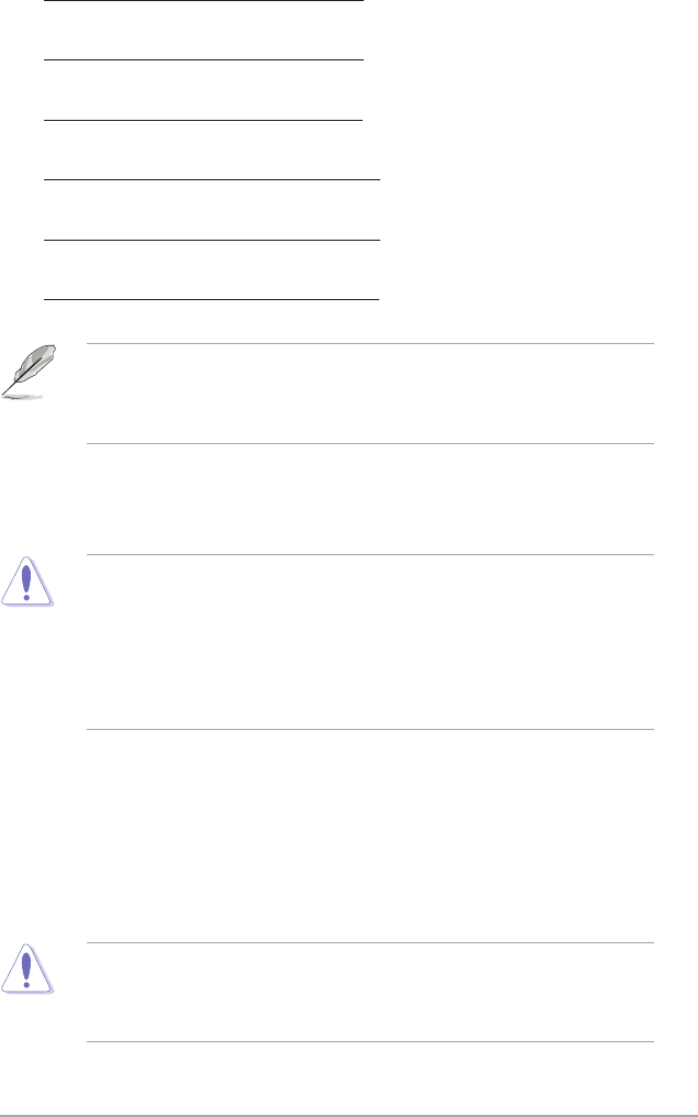
ASUS P6T Deluxe V2 3-21
DRAM READ to READ Delay(DD) [Auto]
Conguration options: [Auto] [2 DRAM Clock] – [9 DRAM Clock]
DRAM READ to READ Delay(DR) [Auto]
Conguration options: [Auto] [2 DRAM Clock] – [9 DRAM Clock]
DRAM READ to READ Delay(SR) [Auto]
Conguration options: [Auto] [4 DRAM Clock] [6 DRAM Clock]
DRAM WRITE to WRITE Delay(DD) [Auto]
Conguration options: [Auto] [2 DRAM Clock] – [9 DRAM Clock]
DRAM WRITE to WRITE Delay(DR) [Auto]
Conguration options: [Auto] [2 DRAM Clock] – [9 DRAM Clock]
DRAM WRITE to WRITE Delay(SR) [Auto]
Conguration options: [Auto] [4 DRAM Clock] [6 DRAM Clock]
The following ten (10) items are adjusted by typing the desired values using
the numeric keypad and press the <Enter> key. You can also use the <+> and
<-> keys to adjust the value. To restore the default setting, type [auto] using the
keyboard and press the <Enter> key.
3.4.7 CPU Voltage [Auto]
Allows you to set the CPU VCore voltage. The values range from 0.85000V to
2.10000V* with a 0.00625V interval.
• Refer to the CPU documentation before setting the CPU Vcore voltage.
Setting a high VCore voltage may damage the CPU permanently, and
setting a low VCore voltage may make the system unstable.
• The value [2.10000V] of the CPU Voltage item is supported only if the
OV_CPU jumper is enabled. Otherwise the maximum voltage supported is
[1.70000V]. See 2. CPU / DRAM Bus / QPI DRAM overvoltage setting on
page 2-25 for details.
3.4.8 CPU PLL Voltage [Auto]
Allows you to set the CPU PLL voltage. The values range from 1.80V to 2.50V with
a 0.02V interval.
3.4.9 QPI/DRAM Core Voltage [Auto]
Allows you to set the QPI/DRAM Core voltage. The values range from 1.20000V to
1.90000V* with a 0.00625V interval.
The value [1.90000V] of the QPI/DRAM Core Voltage item is supported only
if the OV_QPI_DRAM jumper is enabled. Otherwise the maximum voltage
supported is [1.70000V]. See 2. CPU / DRAM Bus / QPI DRAM overvoltage
setting on page 2-25 for details.

3-22 Chapter 3: BIOS setup
3.4.10 IOH Voltage [Auto]
Allows you to set the I/O Hub (IOH) voltage. The values range from 1.10V to 1.70V
with a 0.02V interval.
3.4.11 IOH PCIE Voltage [Auto]
Allows you to set the IOH PCIE voltage. The values range from 1.50V to 2.76V
with a 0.02V interval.
3.4.12 ICH Voltage [Auto]
Allows you to set the I/O Controller Hub (ICH) voltage. The values range from
1.10V to 1.40V with a 0.10V interval.
3.4.13 ICH PCIE Voltage [Auto]
Allows you to set the SB PCIE voltage. The values range from 1.50V to 1.80V with
a 0.10V interval.
3.4.14 DRAM Bus Voltage [Auto]
Allows you to set the DRAM voltage. The values range from 1.50V to 2.46V* with a
0.02V interval.
• The value [2.46V] of the DRAM Bus Voltage item is supported only if
the OV_DRAM_BUS jumper is enabled, otherwise the maximum voltage
supported is [1.90V]. See CPU / DRAM Bus / QPI DRAM overvoltage
setting on page 2-25 for details.
• According to Intel CPU spec, DIMMs with voltage requirement over 1.65V
may damage the CPU permanently. We recommend you install the DIMMs
with the voltage requirement below 1.65V.
• The values of the CPU Voltage, CPU PLL Voltage, QPI/DRAM Core
Voltage, IOH Voltage, IOH PCIE Voltage, ICH Voltage, ICH PCIE
Voltage, and DRAM Bus Voltage items are labeled in different color,
indicating the risk levels of high voltage settings. Refer to the table on the
next page for details.
• The system may need better cooling system to work stably under high
voltage settings.

ASUS P6T Deluxe V2 3-23
Blue Yellow Purple Red
CPU Voltage 0.85000V–
1.22500V
1.23125V–
1.29375V
1.30000V–
1.35000V
1.35625V
1.70000V
CPU PLL Voltage 1.80V–1.90V 1.92V–2.00V 2.02V–2.10V 2.12V–2.50V
QPI/DRAM Core
Voltage
1.20000V–
1.26875V
1.27500V–
1.32500V
1.33125V–
1.40000V
1.40625V–
1.70000V
IOH Voltage 1.10V–1.18V 1.20V–1.24V 1.26V–1.30V 1.32V–1.70V
IOH PCIE Voltage 1.50V–1.58V 1.60V–1.66V 1.68V–1.74V 1.76V–2.76V
ICH Voltage 1.10V–1.20V 1.30V–1.40V N/A N/A
ICH PCIE Voltage 1.50V–1.60V 1.70V–1.80V N/A N/A
DRAM Bus
Voltage 1.50V–1.64V N/A N/A 1.66V–2.46V
3.4.15 DRAM DATA REF Voltage on CHA/B/C [Auto]
Allows you to set the DRAM DATA Reference Voltage on Channel A/B/C. The
values range from 0.395x to 0.630x with a 0.005x interval. Different ratio might
enhance DRAM overclocking ability.
3.4.16 DRAM CTRL REF Voltage on CHA/B/C [Auto]
Allows you to set the DRAM Control Reference Voltage on Channel A/B/C. The
values range from 0.395x to 0.630x with a 0.005x interval. Different ratio might
enhance DRAM overclocking ability.
3.4.17 Load-Line Calibration [Auto]
Allows you to select the CPU Load-Line mode. Set to [Disabled] to follow Intel
specications, or to [Enabled] to improve CPU VDroop directly.
Conguration options: [Auto] [Disabled] [Enabled]
3.4.18 CPU Differential Amplitude [Auto]
Different AMP might enhance BCLK overclocking ability.
Conguration options: [Auto] [700mV] [800mV] [900mV] [1000mV]
3.4.19 CPU Clock Skew [Auto]
Adjusting this item may help enhancing BCLK overclocking ability. You may need
to adjust the NB Clock Skew item at the same time.
Conguration options: [Auto] [Normal] [Delay 100ps]–[Delay 1500ps]

3-24 Chapter 3: BIOS setup
3.4.20 CPU Spread Spectrum [Auto]
Set to [Disabled] to enhance BCLK overclocking ability or [Auto] for EMI control.
Conguration options: [Auto] [Disabled]
3.4.21 IOH Clock Skew [Auto]
Adjusting this item may help enhancing BCLK overclocking ability. You may need
to adjust the CPU Clock Skew item at the same time.
Conguration options: [Auto] [Normal] [Delay 100ps]–[Delay 1500ps]
3.4.22 PCIE Spread Spectrum [Auto]
Set to [Disabled] to enhance PCIE overclocking ability or [Auto] for EMI control.
Conguration options: [Auto] [Disabled] [Enabled]
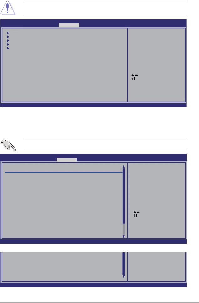
ASUS P6T Deluxe V2 3-25
3.5 Advanced menu
The Advanced menu items allow you to change the settings for the CPU and other
system devices.
Take caution when changing the settings of the Advanced menu items. Incorrect
eld values can cause the system to malfunction.
3.5.1 CPU Conguration
The items in this menu show the CPU-related information that the BIOS
automatically detects.
Select Screen
Select Item
Enter Go to Sub Screen
F1 General Help
F10 Save and Exit
ESC Exit
v02.61 (C)Copyright 1985-2008, American Megatrends, Inc.
CPU Conguration
Chipset
Onboard Devices Conguration
USB Conguration
PCIPnP
BIOS SETUP UTILITY
Main Ai Tweaker Advanced Power Boot Tools Exit
Congure CPU.
The items shown in this screen may be different due to the CPU you installed.
Scroll down to display the following items:
v02.61 (C)Copyright 1985-2008, American Megatrends, Inc.
Execute-Disable Bit [Enabled]
Intel(R) HT Technology [Enabled]
Active Processor Cores [All]
A20M [Disabled]
Intel(R) SpeedStep(TM) Tech [Enabled]
Intel(R) TurboMode tech [Enabled]
Intel(R) C-STATE Tech [Disabled]
Select Screen
Select Item
+- Change Option
F1 General Help
F10 Save and Exit
ESC Exit
v02.61 (C)Copyright 1985-2008, American Megatrends, Inc.
BIOS SETUP UTILITY
Advanced
Congure advanced CPU settings
Module Version:3F.11
Manufacturer:Intel
Brand String:Genuine Intel(R) CPU @ 2.67GHz
Frequency :2.68GHz
BCLK Speed :133MHz
Cache L1 :128 KB
Cache L2 :1024 KB
Cache L3 :8192 KB
Ratio Status:Unlocked (Min:12, Max:20)
Ratio Actual Value :20
CPUID :106A2
CPU Ratio Setting [Auto]
C1E Support [Enabled]
Hardware Prefetcher [Enabled]
Adjacent Cache Line Prefetch [Enabled]
Intel(R) Virtualization Tech [Enabled]
CPU TM function [Enabled]
Sets the ratio between
CPU Core Clock and the
FSB Frequency.
NOTE: If an invalid
ratio is set in CMOS
then actual and
setpoint values may
differ.

3-26 Chapter 3: BIOS setup
CPU Ratio Setting [Auto]
Allows you to adjust the ratio between CPU Core Clock and BCLK Frequency. Use
the <+> and <-> keys to adjust the value.
Conguration options: [Auto] [12.0] [13.0] [14.0] [15.0] [16.0] [17.0] [18.0] [19.0]
[20.0]
C1E Support [Enabled]
Allows you to enable or disable Enhanced Halt State support.
Conguration options: [Disabled] [Enabled]
Hardware Prefetcher [Enabled]
Allows you to enable or disable the Hardware Prefetcher function.
Conguration options: [Disabled] [Enabled]
Adjacent Cache Line Prefetch [Enabled]
Allows you to enable or disable the Adjacent Cache Line Prefetch function.
Conguration options: [Disabled] [Enabled]
Intel(R) Virtualization Tech [Enabled]
The Intel® Virtualization Technology allows a hardware platform to run multiple
operating systems separately and simultaneously, enabling one system to virtually
function as several systems.
Conguration options: [Disabled] [Enabled]
CPU TM Function [Enabled]
This function enables the overheated CPU to throttle the clock speed to cool down.
Conguration options: [Disabled] [Enabled]
Execute-Disable Bit [Enabled]
Allows you to enable or disable the No-Execution Page Protection Technology.
Setting this item to [Disabled] forces the XD feature ag to always return to zero
(0).
Conguration options: [Disabled] [Enabled]
Intel(R) HT Technology [Enabled]
Allows you to enable or disable the Intel Hyper-Threading Technology function.
When disabled, only one thread per activated core is enabled.
Conguration options: [Enabled] [Disabled]
Active Processor Cores [All]
Allows you to choose the number of CPU cores to activate in each processor
package.
Conguration options: [All] [1] [2]

ASUS P6T Deluxe V2 3-27
A20M [Disabled]
Legacy OSes and APs may need A20M enabled.
Conguration options: [Disabled] [Enabled]
Intel(R) SpeedStep (TM) Tech [Enabled]
When set to [Disabled], the CPU runs at its default speed. When set to [Enabled],
the CPU speed is controlled by the operating system.
Conguration options: [Disabled] [Enabled]
Intel(R) TurboMode tech [Enabled]
Turbo mode allows processor cores to run faster than marked frequency in specic
condition.
Conguration options: [Disabled] [Enabled]
Intel(R) C-STATE Tech [Disabled]
The Intel® C-State Technology allows the CPU to save more power under idle
mode. Enable this item only when you install a C-State Technology-supported
CPU.
Conguration options: [Disabled] [Enabled]
C State package limit setting [Auto]
This item appears only when you set the Intel(R) C-STATE Tech item to [Enabled].
We recommend that you set this item to [Auto] for BIOS to automatically detect the
C-State mode supported by your CPU.
Conguration options: [Auto] [C1] [C3] [C6] [C7]
3-28 Chapter 3: BIOS setup
3.5.2 Chipset
The Chipset menu allows you to change the advanced chipset settings. Select an
item then press <Enter> to display the sub-menu.
NorthBridge Chipset Conguration
PCI Express Selector [Auto]
Allows you to decide the Link Width of the PCIe x16_2 slot and PCIe x16_3
slot.
Conguration options: [Auto] [x8 x8 Mode] [x16 x1 Mode]
Advanced Chipset Settings
WARMING: Setting wrong values in below sections
may cause system to malfunction.
North Bridge Conguration
Intel VT-d Conguration
Congure North Bridge
features.
BIOS SETUP UTILITY
Advanced
NorthBridge Chipset Conguration
Revision :B0
PCI Express Selector [Auto]
BIOS SETUP UTILITY
Advanced
Select PCIE Slot#2
and PCIE Slot#3 Link
Width x8 + x8 or
x16 + x1
Intel VT-d Conguration
Intel VT-d [Disabled]
Allows you to enable or disable the Intel Virtualization Technology for
Directed I/O.
Conguration options: [Disabled] [Enabled]
Intel VT-d Conguration
Intel VT-d [Disabled]
BIOS SETUP UTILITY
Advanced
Intel Virtualization
Technology for
Directed I/O.

ASUS P6T Deluxe V2 3-29
High Denition Audio [Enabled]
Allows you to enable or disable the High Denition Audio Controller.
Conguration options: [Enabled] [Disabled]
Front Panel Type [HD Audio]
Allows you to set the front panel audio connector (AAFP) mode to legacy
AC’97 or high-denition audio depending on the audio standard that the front
panel audio module supports.
Conguration options: [AC97] [HD Audio]
Marvell Storage Controller [Enabled]
Allows you to enable or disable the onboard Marvell storage controller.
Conguration options: [Enabled] [Disabled]
Marvell Storage Boot ROM [Enabled]
This item appears only when you set the previous item to [Enabled].
Conguration options: [Disabled] [Enabled]
MarvelI LAN1/2 [Enabled]
Allows you to enable or disable the onboard Marvell LAN port1/2.
Conguration options: [Enabled] [Disabled]
LAN Boot ROM [Disabled]
This item appears only when you enable the previous item.
Conguration options: [Disabled] [Enabled]
Onboard 1394 Controller [Enabled]
Allows you to enabled or disable the onboard IEEE 1394a controller.
Conguration options: [Enabled] [Disabled]
3.5.3 Onboard Device Conguration
Onboard Devices Conguration
High Denition Audio [Enabled]
Front Panel Type [HD Audio]
Marvell Storage Controller [Enabled]
Marvell Storage Boot ROM [Enabled]
Marvell LAN1 [Enabled]
Marvell LAN2 [Enabled]
LAN Boot ROM [Disabled]
Onboard 1394 Controller [Enabled]
BIOS SETUP UTILITY
Advanced
Options
Enabled
Disabled
3-30 Chapter 3: BIOS setup
3.5.4 USB Conguration
The items in this menu allows you to change the USB-related features. Select an
item then press <Enter> to display the conguration options.
Select Screen
Select Item
+- Change Option
F1 General Help
F10 Save and Exit
ESC Exit
v02.61 (C)Copyright 1985-2008, American Megatrends, Inc.
USB Conguration
USB Devices Enabled:
1 Mouse
USB Functions [Enabled]
USB 2.0 Controller [Enabled]
USB 2.0 Controller Mode [HiSpeed]
BIOS EHCI Hand-Off [Enabled]
Legacy USB Support [Auto]
Enables support for
legacy USB. AUTO
option disables
legacy support if
no USB devices are
connected.
BIOS SETUP UTILITY
Advanced
The USB Devices Enabled item shows the auto-detected values. If no USB
device is detected, the item shows None.
USB Functions [Enabled]
Allows you to enable or disable the USB Host Controllers.
Conguration options: [Disabled] [Enabled]
The following items appear only when you set USB Functions to [Enabled].
USB 2.0 Controller [Enabled]
Allows you to enable or disable the USB 2.0 controller.
Conguration options: [Enabled] [Disabled]
USB 2.0 Controller Mode [HiSpeed]
Allows you to set the USB 2.0 controller mode to HiSpeed (480 Mbps) or
FullSpeed (12 Mbps).
Conguration options: [FullSpeed] [HiSpeed]
The USB 2.0 Controller Mode item appears only when you enable the USB
2.0 Controller.
BIOS EHCI Hand-off [Enabled]
Allows you to enable the support for operating systems without an EHCI hand-off
feature.
Conguration options: [Disabled] [Enabled]
ASUS P6T Deluxe V2 3-31
3.5.5 PCIPnP
The PCIPnP menu items allow you to change the advanced settings for PCI/PnP
devices.
Plug And Play O/S [No]
When set to [NO], BIOS congures all the devices in the system. When set to
[YES] and if you install a Plug and Play operating system, the operating system
congures the Plug and Play devices not required for boot.
Conguration options: [No] [Yes]
Select Screen
Select Item
+- Change Option
F1 General Help
F10 Save and Exit
ESC Exit
v02.61 (C)Copyright 1985-2008, American Megatrends, Inc.
Advanced PCI/PnP Settings
WARNING: Setting wrong values in below sections
may cause system to malfunction.
Plug And Play O/S [No]
NO: lets the BIOS
congure all the
devices in the system.
YES: lets the
operating system
congure Plug and
Play (PnP) devices not
required for boot if
your system has a Plug
and Play operating
system.
BIOS SETUP UTILITY
Advanced
Legacy USB Support [Auto]
Allows you to enable or disable the support for legacy USB devices. Setting to
[Auto] allows the system to detect the presence of USB devices at startup. If
detected, the USB controller legacy mode is enabled. If no USB device is detected,
the legacy USB support is disabled.
Conguration options: [Disabled] [Enabled] [Auto]

3-32 Chapter 3: BIOS setup
3.6 Power menu
The Power menu items allow you to change the settings for the Advanced
Power Management (APM). Select an item then press <Enter> to display the
conguration options.
3.6.1 Suspend Mode [Auto]
Allows you to select the Advanced Conguration and Power Interface (ACPI) state
to be used for system suspend.
Conguration options: [S1 (POS) Only] [S3 Only] [Auto]
3.6.2 Repost Video on S3 Resume [No]
Determines whether to invoke VGA BIOS POST on S3/STR resume.
Conguration options: [No] [Yes]
3.6.3 ACPI 2.0 Support [Disabled]
Add additional tables as per ACPI 2.0 specications.
Conguration options: [Disabled] [Enabled]
3.6.4 ACPI APIC Support [Enabled]
Allows you to enable or disable the Advanced Conguration and Power Interface
(ACPI) support in the Advanced Programmable Interrupt Controller (APIC). When
set to [Enabled], the ACPI APIC table pointer is included in the RSDT pointer list.
Conguration options: [Disabled] [Enabled]
Select Screen
Select Item
+- Change Option
F1 General Help
F10 Save and Exit
ESC Exit
v02.61 (C)Copyright 1985-2008, American Megatrends, Inc.
BIOS SETUP UTILITY
Main Ai Tweaker Advanced Power Boot Tools Exit
Suspend Mode [Auto]
Repost Video on S3 Resume [No]
ACPI 2.0 Support [Disabled]
ACPI APIC Support [Enabled]
APM Conguration
Hardware Monitor
Select the ACPI state
used for System
Suspend.

ASUS P6T Deluxe V2 3-33
3.6.5 APM Conguration
Restore On AC Power Loss [Power Off]
When set to [Power Off], the system goes into off state after an AC power loss.
When set to [Power On], the system goes on after an AC power loss. When set to
[Last State], the system goes into either off or on state, whatever the system state
was before the AC power loss.
Conguration options: [Power Off] [Power On] [Last State]
Power On By RTC Alarm [Disabled]
Allows you to enable or disable RTC to generate a wake event. When this item
is set to [Enabled], the items RTC Alarm Date/ RTC Alarm Hour/ RTC Alarm
Minute/ RTC Alarm Second will become user-congurable with set values.
Conguration options: [Disabled] [Enabled]
Power On By PCI Devices [Disabled]
Allows you to enable or disable the PME to wake up from S5 by PCI devices.
Conguration options: [Disabled] [Enabled]
Power On By PCIE Devices [Disabled]
Allows you to enable or disable the PCIE devices to generate a wake event.
Conguration options: [Disabled] [Enabled]
Power On By PS/2 Keyboard [Disabled]
Allows you to disable the Power On by PS/2 keyboard function or set specic keys
on the PS/2 keyboard to turn on the system. This feature requires an ATX power
supply that provides at least 1A on the +5VSB lead.
Conguration options: [Disabled] [Space Bar] [Ctrl-Esc] [Power Key]
Select Screen
Select Item
+- Change Option
F1 General Help
F10 Save and Exit
ESC Exit
v02.61 (C)Copyright 1985-2008, American Megatrends, Inc.
BIOS SETUP UTILITY
Power
APM Conguration
Restore on AC Power Loss [Power Off]
Power On By RTC Alarm [Disabled]
Power On By PCI Devices [Disabled] [Disabled]
Power On By PCIE Devices [Disabled]
Power On By PS/2 Keyboard [Disabled] PS/2 Keyboard [Disabled]
<Enter> to select
whether or not to
restart the system
after AC power loss.
3-34 Chapter 3: BIOS setup
3.6.6 Hardware Monitor
CPU Temperature [xxxºC/xxxºF]
MB Temperature [xxxºC/xxxºF]
The onboard hardware monitor automatically detects and displays the motherboard
and CPU temperatures. Select [Ignored] if you do not wish to display the detected
temperatures.
CPU Fan Speed [xxxxRPM] or [Ignored] / [N/A]
The onboard hardware monitor automatically detects and displays the CPU
fan speed in rotations per minute (RPM). If the fan is not connected to the
motherboard, the eld shows [N/A].
CPU Q-Fan Control [Disabled]
Allows you to enable or disable the CPU Q-fan control feature.
Conguration options: [Disabled] [Enabled]
The following item appears only when you enable the CPU Q-Fan Control item.
CPU Fan Profile [Standard]
Allows you to set the appropriate performance level of the ASUS Q-Fan.
When set to [Standard], the CPU fan automatically adjusts depending on
the CPU temperature. Set this item to [Silent] to minimize fan speed for
quiet CPU fan operation, or [Turbo] to achieve maximum CPU fan speed.
Conguration options: [Standard] [Silent] [Turbo]
Chassis Fan 1/2/3 Speed [xxxxRPM] or [Ignored] / [N/A]
The onboard hardware monitor automatically detects and displays the chassis
fan speed in rotations per minute (RPM). If the fan is not connected to the
motherboard, the eld shows [N/A].
Select Screen
Select Item
+- Change Field
F1 General Help
F10 Save and Exit
ESC Exit
v02.61 (C)Copyright 1985-2008, American Megatrends, Inc.
Hardware Monitor
CPU Temperature [35ºC/95ºF]
MB Temperature [34ºC/93ºF]
CPU Fan Speed [1721RPM]
CPU Q-Fan Control [Disabled]
Chassis Fan 1 Speed [N/A]
Chassis Fan 2 Speed [N/A]
Chassis Fan 3 Speed [N/A]
Chassis Q-Fan Control [Disabled]
Power Fan Speed [N/A]
CPU Voltage [ 0.832V]
3.3V Voltage [ 3.200V]
5V Voltage [ 5.094V]
12V Voltage [12.137V]
CPU Temperature
BIOS SETUP UTILITY
Power

ASUS P6T Deluxe V2 3-35
Chassis Q-Fan Control [Disabled]
Allows you to enable or disable the Chassis Q-fan control feature.
Conguration options: [Disabled] [Enabled]
The following item appears only when you enable the Chassis Q-Fan Control
item.
Chassis Fan Profile [Standard]
Allows you to set the appropriate performance level of the ASUS Q-Fan.
When set to [Standard], the chassis fan automatically adjusts depending
on the chassis temperature. Set this item to [Silent] to minimize fan speed
for quiet chassis fan operation, or [Turbo] to achieve maximum chassis fan
speed.
Conguration options: [Standard] [Silent] [Turbo]
Power Fan Speed [xxxxRPM] or [Ignored] / [N/A]
The onboard hardware monitor automatically detects and displays the power
fan speed in rotations per minute (RPM). If the fan is not connected to the
motherboard, the eld shows [N/A].
CPU Voltage, 3.3V Voltage, 5V Voltage, 12V Voltage
The onboard hardware monitor automatically detects the voltage output through
the onboard voltage regulators. Select [Ignored] if you do not want to detect this
item.
3-36 Chapter 3: BIOS setup
3.7 Boot menu
The Boot menu items allow you to change the system boot options. Select an item
then press <Enter> to display the sub-menu.
3.7.1 Boot Device Priority
1st ~ xxth Boot Device [xxx Drive]
These items specify the boot device priority sequence from the available devices.
The number of device items that appears on the screen depends on the number of
devices installed in the system.
Conguration options: [1st FLOPPY DRIVE] [Hard Drive] [ATAPI CD-ROM]
[Disabled]
Select Screen
Select Item
+- Change Option
F1 General Help
F10 Save and Exit
ESC Exit
v02.61 (C)Copyright 1985-2008, American Megatrends, Inc.
BIOS SETUP UTILITY
Boot
Boot Device Priority
1st Boot Device [1st FLOPPY DRIVE]
2nd Boot Device [Hard Drive]
3rd Boot Device [ATAPI CD-ROM]
Species the boot
sequence from the
available devices.
A device enclosed in
parenthesis has been
disabled in the
corresponding type
menu.
Select Screen
Select Item
Enter Go to Sub Screen
F1 General Help
F10 Save and Exit
ESC Exit
v02.61 (C)Copyright 1985-2008, American Megatrends, Inc.
BIOS SETUP UTILITY
Main Ai Tweaker Advanced Power Boot Tools Exit
Boot Settings
Boot Device Priority
Boot Settings Conguration
Security
Species the Boot
Device Priority
sequence.
A virtual oppy disk
drive (Floppy Drive B:
) may appear when you
set the CD-ROM drive
as the rst boot
device.
ASUS P6T Deluxe V2 3-37
3.7.2 Boot Settings Conguration
Quick Boot [Enabled]
Enabling this item allows the BIOS to skip some power on self tests (POST) while
booting to decrease the time needed to boot the system. When set to [Disabled],
BIOS performs all the POST items.
Conguration options: [Disabled] [Enabled]
Full Screen Logo [Enabled]
This allows you to enable or disable the full screen logo display feature.
Conguration options: [Disabled] [Enabled]
Set this item to [Enabled] to use the ASUS MyLogo 3 feature.
AddOn ROM Display Mode [Force BIOS]
Sets the display mode for option ROM.
Conguration options: [Force BIOS] [Keep Current]
Bootup Num-Lock [On]
Allows you to select the power-on state for the NumLock.
Conguration options: [Off] [On]
Wait for ‘F1’ If Error [Enabled]
When set to [Enabled], the system waits for the <F1> key to be pressed when error
occurs.
Conguration options: [Disabled] [Enabled]
Hit ‘DEL’ Message Display [Enabled]
When set to [Enabled], the system displays the message “Press DEL to run Setup”
during POST.
Conguration options: [Disabled] [Enabled]
Select Screen
Select Item
+- Change Option
F1 General Help
F10 Save and Exit
ESC Exit
v02.61 (C)Copyright 1985-2008, American Megatrends, Inc.
Boot Settings Conguration
Quick Boot [Enabled]
Full Screen Logo [Enabled]
AddOn ROM Display Mode [Force BIOS]
Bootup Num-Lock [On]
Wait for ‘F1’ if Error [Enabled]
Hit ‘DEL’ Message Display [Enabled]
Allows BIOS to skip
certain tests while
booting. This will
decrease the time
needed to boot the
system.
BIOS SETUP UTILITY
Boot
3-38 Chapter 3: BIOS setup
3.7.3 Security
The Security menu items allow you to change the system security settings. Select
an item then press <Enter> to display the conguration options.
Change Supervisor Password
Select this item to set or change the supervisor password. The Supervisor
Password item on top of the screen shows the default Not Installed. After you set
a password, this item shows Installed.
To set a Supervisor Password:
1. Select the Change Supervisor Password item and press <Enter>.
2. From the password box, type a password composed of at least six letters
and/or numbers, then press <Enter>.
3. Conrm the password when prompted.
The message “Password Installed” appears after you successfully set your
password.
To change the supervisor password, follow the same steps as in setting a user
password.
To clear the supervisor password, select the Change Supervisor Password then
press <Enter>. The message “Password Uninstalled” appears.
If you forget your BIOS password, you can clear it by erasing the CMOS Real
Time Clock (RTC) RAM. See section 2.6 Jumpers for information on how to
erase the RTC RAM.
After you have set a supervisor password, the other items appear to allow you to
change other security settings.
Select Screen
Select Item
Enter Change
F1 General Help
F10 Save and Exit
ESC Exit
v02.61 (C)Copyright 1985-2008, American Megatrends, Inc.
Security Settings
Supervisor Password : Not Installed
User Password : Not Installed
Change Supervisor Password
Change User Password
<Enter> to change
password.
<Enter> again to
disabled password.
BIOS SETUP UTILITY
Boot

ASUS P6T Deluxe V2 3-39
User Access Level [Full Access]
This item allows you to select the access restriction to the Setup items.
Conguration options: [No Access] [View Only] [Limited] [Full Access]
[No Access] prevents user access to the Setup utility.
[View Only] allows access but does not allow change to any eld.
[Limited] allows changes only to selected elds, such as Date and Time.
[Full Access] allows viewing and changing all the elds in the Setup utility.
Change User Password
Select this item to set or change the user password. The User Password item on
top of the screen shows the default Not Installed. After you set a password, this
item shows Installed.
To set a User Password
1. Select the Change User Password item and press <Enter>.
2. On the password box that appears, type a password composed of at least six
letters and/or numbers, then press <Enter>.
3. Conrm the password when prompted.
The message “Password Installed” appears after you set your password
successfully.
To change the user password, follow the same steps as in setting a user password.
Clear User Password
Select this item to clear the user password.
Password Check [Setup]
When set to [Setup], BIOS checks for user password when accessing the Setup
utility. When set to [Always], BIOS checks for user password both when accessing
Setup and booting the system.
Conguration options: [Setup] [Always]
Security Settings
Supervisor Password : Installed
User Password : Installed
Change Supervisor Password
User Access Level [Full Access]
Change User Password
Clear User Password
Password Check [Setup]
<Enter> to change
password.
<Enter> again to
disabled password.
BIOS SETUP UTILITY
Boot
3-40 Chapter 3: BIOS setup
3.8 Tools menu
The Tools menu items allow you to congure options for special functions. Select
an item then press <Enter> to display the sub-menu.
Select Screen
Select Item
+- Change Field
Enter Go to Sub Screen
F1 General Help
F10 Save and Exit
ESC Exit
v02.61 (C)Copyright 1985-2008, American Megatrends, Inc.
BIOS SETUP UTILITY
Main Ai Tweaker Advanced Power Boot Tools Exit
ASUS EZ Flash 2
Express Gate [Enabled]
Enter OS Timer [10 Seconds]
Reset User Data [No]
ASUS O.C. Prole
Ai Net 2
Press ENTER to run
the utility to select
and update BIOS.
This utility doesn't
support :
1.NTFS format
3.8.1 ASUS EZ Flash 2
Allows you to run ASUS EZ Flash 2. When you press <Enter>, a conrmation
message appears. Use the left/right arrow key to select between [Yes] or [No],
then press <Enter> to conrm your choice. Please see page 3-4, section 3.1.2 for
details.
ASUSTek EZ Flash 2 BIOS ROM Utility V3.30
Current ROM Update ROM
A:
Note
[Enter] Select or Load [Tab] Switch [V] Drive Info
[Up/Down/Home/End] Move [B] Backup [Esc] Exit
FLASH TYPE: MXIC 25L1605A
PATH: A:\
BOARD: P6T Deluxe V2
VER: 0309
DATE: 09/15/2008
BOARD: Unknown
VER: Unknown
DATE: Unknown

ASUS P6T Deluxe V2 3-41
3.8.2 Express Gate [Enabled]
Allows you to enable or disable the ASUS Express Gate feature. The ASUS
Express Gate feature is a unique instant-on environment that provides quick
access to the Internet browser and Skype. Refer to section 4.3.10 ASUS Express
GATE SSD for details.
Conguration options: [Enabled] [Disabled]
Enter OS Timer [10 Seconds]
Sets countdown duration that the system waits at the Express Gate’s rst
screen before starting Windows or other installed OS. Choose [Prompt User]
to stay at the rst screen of Express Gate for user action.
Conguration options: [Prompt User] [1 second] [3 seconds] [5 seconds]
[10 seconds] [15 seconds] [20 seconds] [30 seconds]
Reset User Data [No]
Allows you to clear Express Gate’s user data.
Conguration options: [No] [Reset]
When setting this item to [Reset], make sure to save the setting to the BIOS
so that the user data will be cleared the next time you enter the Express
Gate. User data includes the Express Gate’s settings as well as any personal
information stored by the web browser (bookmarks, cookies, browsing
history, etc.). This is useful in the rare case where corrupt settings prevent
the Express Gate environment from launching properly.
The rst time wizard will run again when you enter the Express Gate
environment after clearing its settings.
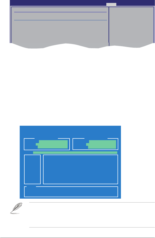
3-42 Chapter 3: BIOS setup
3.8.3 ASUS O.C. Prole
This item allows you to store or load multiple BIOS settings.
Add Your CMOS Prole.
Allows you to save the current BIOS le to the BIOS Flash. In the Name sub-item,
type your prole name and press <Enter>, and then choose a prole number to
save your CMOS settings in the Save To sub-item. You can save two (2) CMOS
proles.
Load CMOS Prole.
Allows you to load the previous BIOS settings saved in the BIOS Flash. Press
<Enter>, and choose a prole to load.
Start O.C. Prole
Allows you to run the utility to save and load CMOS. Press <Enter> to run the
utility.
ASUSTek O.C. Prole Utility V1.30
Current CMOS Restore CMOS
A:
Note
[Enter] Select or Load [Tab] Switch [V] Drive Info
[Up/Down/Home/End] Move [B] Backup [Esc] Exit
PATH: A:\
BOARD: P6T Deluxe V2
VER: 0309
DATE: 09/15/2008
BOARD: Unknown
VER: Unknown
DATE: Unknown
• This function can support devices such as a USB ash disk or a oppy disk
with FAT 32/16 format and single partition only.
• DO NOT shut down or reset the system while updating the BIOS to prevent
the system boot failure!
BIOS SETUP UTILITY
Tools
O.C. PROFILE Conguration
O.C. Prole 1 Status : Default-Prole
O.C. Prole 2 Status : Default-Prole
Add Your CMOS Prole.
Name : [Default-Prole]
Save To : [Uninstalled]
Load CMOS Prole.
Load From : [Blank]
Start O.C. Prole
Save BIOS settings
to Prole 1

ASUS P6T Deluxe V2 3-43
3.8.4 Ai Net 2
Check Marvell LAN Cable [Disabled]
Enables or disables checking of the Marvell LAN cable during the Power-On
Self-Test (POST).
Conguration options: [Disabled] [Enabled]
v02.61 (C)Copyright 1985-2008, American Megatrends, Inc.
AI NET 2
Pair Status Length
Check Marvell LAN cable [Disabled]
Check Marvell LAN
cable during POST.
BIOS SETUP UTILITY
Tools
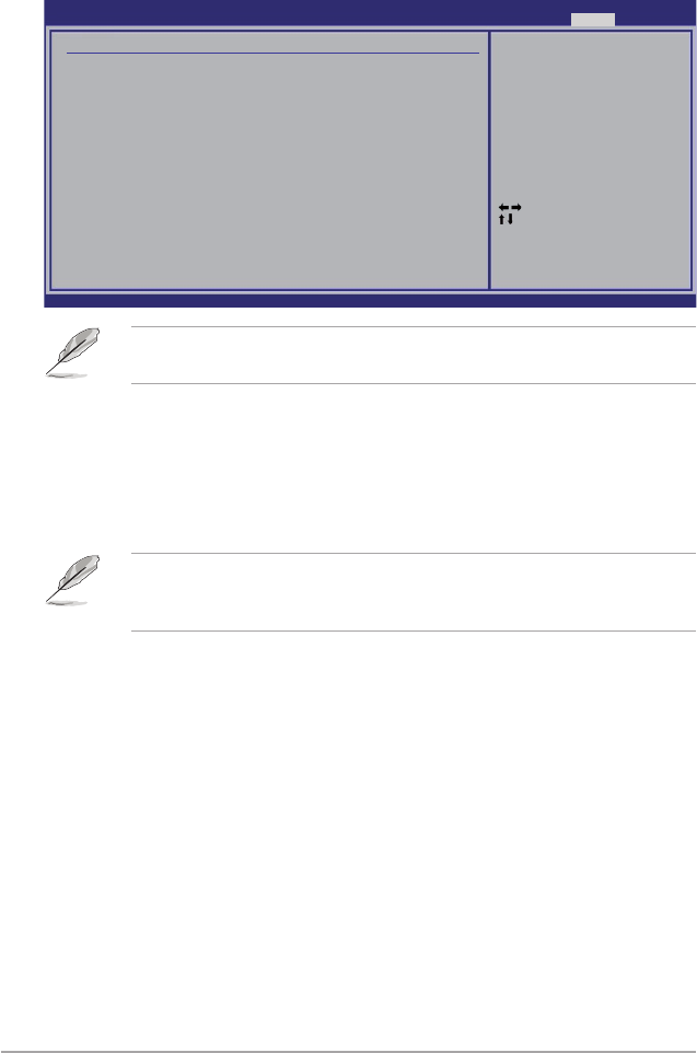
3-44 Chapter 3: BIOS setup
Pressing <Esc> does not immediately exit this menu. Select one of the options
from this menu or <F10> from the legend bar to exit.
3.9 Exit menu
The Exit menu items allow you to load the optimal or failsafe default values for the
BIOS items, and save or discard your changes to the BIOS items.
Exit & Save Changes
Once you are nished making your selections, choose this option from the Exit
menu to ensure the values you selected are saved to the CMOS RAM. An onboard
backup battery sustains the CMOS RAM so it stays on even when the PC is turned
off. When you select this option, a conrmation window appears. Select Ok to save
changes and exit.
If you attempt to exit the Setup program without saving your changes, the
program prompts you with a message asking if you want to save your changes
before exiting. Press <Enter> to save the changes while exiting.
Exit & Discard Changes
Select this option only if you do not want to save the changes that you made to
the Setup program. If you made changes to elds other than System Date, System
Time, and Password, the BIOS asks for a conrmation before exiting.
Discard Changes
This option allows you to discard the selections you made and restore the
previously saved values. After selecting this option, a conrmation appears. Select
Ok to discard any changes and load the previously saved values.
Load Setup Defaults
This option allows you to load the default values for each of the parameters on the
Setup menus. When you select this option or if you press <F5>, a conrmation
window appears. Select Ok to load default values. Select Exit & Save Changes or
make other changes before saving the values to the non-volatile RAM.
Select Screen
Select Item
Enter Go to Sub Screen
F1 General Help
F10 Save and Exit
ESC Exit
v02.61 (C)Copyright 1985-2008, American Megatrends, Inc.
BIOS SETUP UTILITY
Main Ai Tweaker Advanced Power Boot Tools Exit
Exit Options
Exit & Save Changes
Exit & Discard Changes
Discard Changes
Load Setup Defaults
Exit system setup
after saving the
changes.
F10 key can be used
for this operation.
4
Software
support
This chapter describes the contents of
the support DVD that comes with the
motherboard package and the software.

ASUS P6T Deluxe V2
Chapter summary 4
4.1 Installing an operating system ................................................... 4-1
4.2 Support DVD information ............................................................ 4-1
4.3 Software information ................................................................... 4-9
4.4 RAID congurations .................................................................. 4-44
4.5 Creating a RAID driver disk ....................................................... 4-53
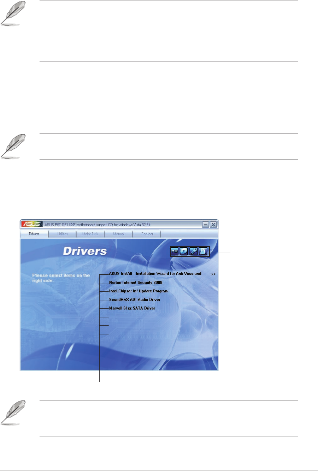
ASUS P6T Deluxe V2 4-1
If Autorun is NOT enabled in your computer, browse the contents of the support
DVD to locate the le ASSETUP.EXE from the BIN folder. Double-click the
ASSETUP.EXE to run the DVD.
4.1 Installing an operating system
This motherboard supports Windows® XP/ 64-bit XP/ Vista™ operating systems
(OS). Always install the latest OS version and corresponding updates to maximize
the features of your hardware.
4.2 Support DVD information
The support DVD that came with the motherboard package contains the drivers,
software applications, and utilities that you can install to avail all motherboard
features.
4.2.1 Running the support DVD
Place the support DVD to the optical drive. The DVD automatically displays the
Drivers menu if Autorun is enabled in your computer.
• Motherboard settings and hardware options vary. Use the setup
procedures presented in this chapter for reference only. Refer to your OS
documentation for detailed information.
• Make sure that you install the Windows® XP Service Pack2 or later versions
before installing the drivers for better compatibility and system stability.
The contents of the support DVD are subject to change at any time without
notice. Visit the ASUS website(www.asus.com) for updates.
Click an item to install
Click an icon to
display support
DVD/motherboard
information
ASUS TurboV
ASUS EPU 6-Engine
ASUS Express Gate SSD

4-2 Chapter 4: Software support
4.2.2 Drivers menu
The Drivers menu shows the available device drivers if the system detects installed
devices. Install the necessary drivers to activate the devices.
ASUS InstAll - Installation Wizard for Anti-Virus and Drivers Utility
Installs all of the drivers and anti-virus software through the Installation Wizard.
Norton Internet Security 2008
Installs Norton® Internet Security 2008 to protect your PC from the latest online
threats.
Intel Chipset Inf Update Program
Installs the Intel® chipset Inf update program.
SoundMAX ADI Audio Driver
Installs the SoundMAX® AD2000B audio driver and application.
Marvell 61xx SATA Driver
Installs the Marvell® 61xx SATA driver.
ASUS TurboV
Installs ASUS TurboV, the advanced overclocking tool for extreme O.C. record.
ASUS EPU-6 Engine
Installs the ASUS EPU-6 Engine driver and utility.
ASUS Express Gate SSD
Installs the ASUS Express Gate SSD update application.
ASUS TurboV
ASUS EPU 6-Engine
ASUS Express Gate SSD
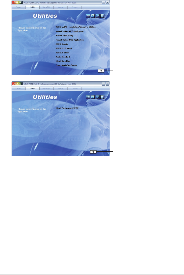
ASUS P6T Deluxe V2 4-3
4.2.3 Utilities menu
The Utilities menu shows the applications and other software that the motherboard
supports.
ASUS InstAll - Installation Wizard for Utilities
Installs all of the utilities through the Installation Wizard.
Marvell Yukon VCT Application
Installs Marvell Yukon Virtual Cable Tester Driver.
Marvell RAID Utility
Installs Marvell RAUD Utility.
Marvell Yukon NCU Application
Installs the Marvell® Yukon Network Conguration Utility application.
Click to display
the next page
Click to return
to the previous
page
WinZip 11

4-4 Chapter 4: Software support
ASUS Update
The ASUS Update utility allows you to update the motherboard BIOS in Windows®
environment. This utility requires an Internet connection either through a network
or an Internet Service Provider (ISP).
ASUS PC Probe II
This smart utility monitors the fan speed, CPU temperature, and system voltages,
and alerts you of any detected problems. This utility helps you keep your computer
in healthy operating condition.
ASUS AI Suite
The ASUS AI Suite is an innovative application to do overclocking, fan control,
power saving and quiet thermal control.
Adobe Reader 8
Installs the Adobe® Reader that allows you to open, view, and print documents in
Portable Document Format (PDF).
Ulead Burn.Now
Installs the Ulead Burn.Now application for Audio DVD, CD and data disc creation.
Corel MediaOne Starter
Installs the Corel MediaOne Starter application to easily manage, edit share and
protect your multimedia data.
Ulead PhotoImpact 12 SE
Installs the PhotoImpact image editing software.
Winzip 11
Installs the Winzip utility for easy le-compression and protection.

ASUS P6T Deluxe V2 4-5
4.2.4 Make disk menu
The Make disk menu contains items to create the Intel ICH10R or Marvell® 61xx
driver disk.
Intel ICH10R 32/64 bit RAID/AHCI Driver Disk
Allows you to create an ICH10R 32/64bit RAID/AHCI driver disk.
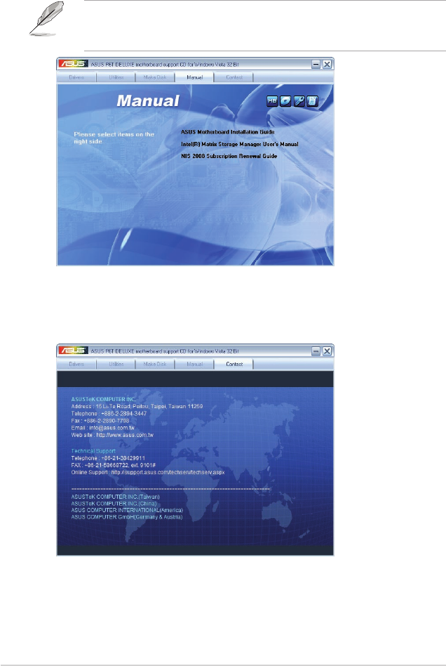
4-6 Chapter 4: Software support
4.2.5 Manual menu
The Manual menu contains a list of supplementary user manuals. Click an item to
open the folder of the user manual.
Most user manual les are in Portable Document Format (PDF). Install the
Adobe® Acrobat® Reader from the Utilities menu before opening a user manual
le.
4.2.6 ASUS Contact information
Click the Contact tab to display the ASUS contact information. You can also nd
this information on the inside front cover of this user guide.
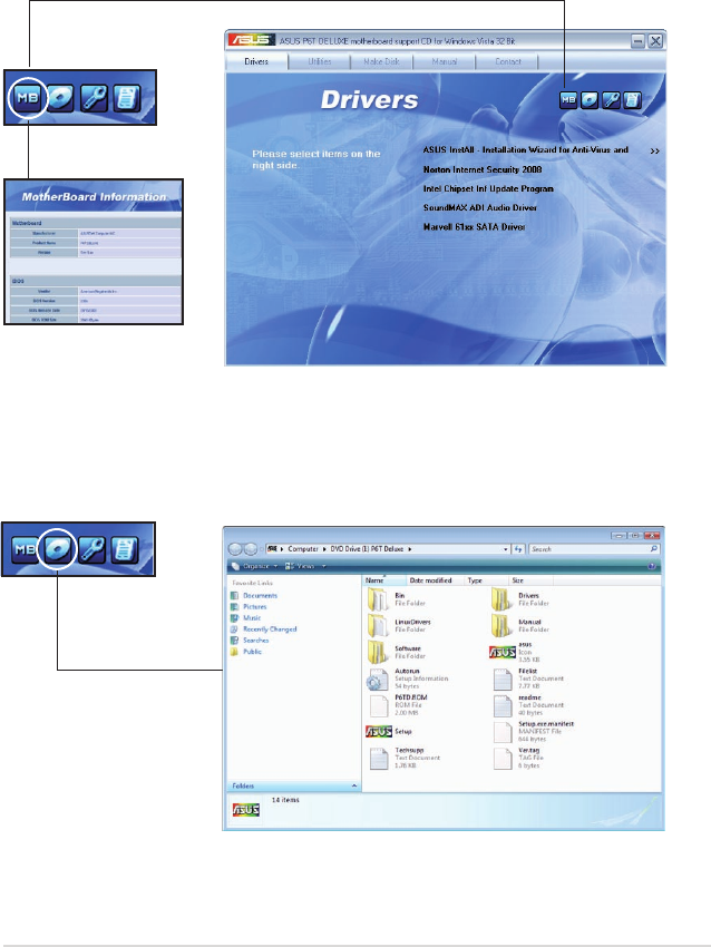
ASUS P6T Deluxe V2 4-7
ASUS TurboV
ASUS EPU 6-Engine
ASUS Express Gate SSD
Browse this DVD
Displays the support DVD contents in graphical format.
4.2.7 Other information
The icons on the top right corner of the screen give additional information on the
motherboard and the contents of the support DVD. Click an icon to display the
specied information.
Motherboard Info
Displays the general specications of the motherboard.
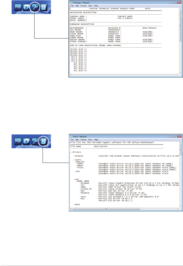
4-8 Chapter 4: Software support
Technical support Form
Displays the ASUS Technical Support Request Form that you have to ll out when
requesting technical support.
Filelist
Displays the contents of the support DVD in text format.
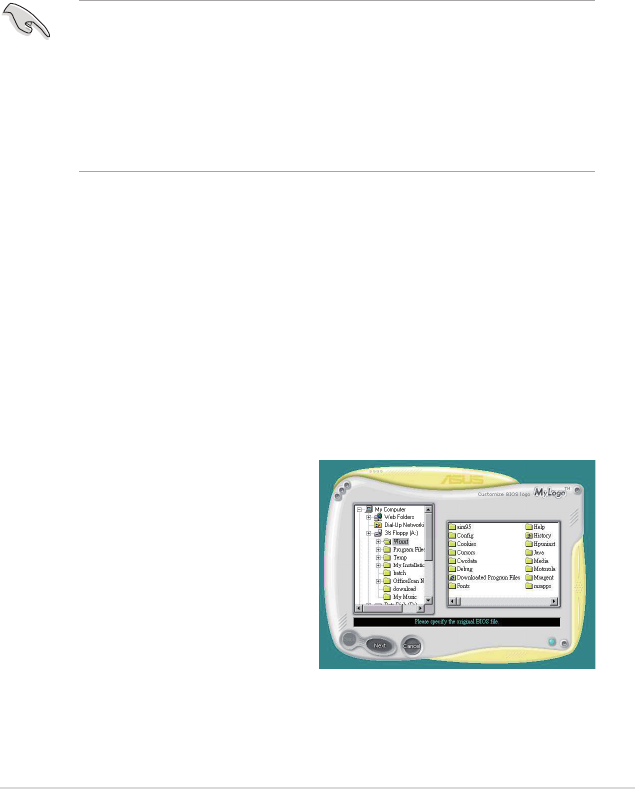
ASUS P6T Deluxe V2 4-9
4.3 Software information
Most of the applications in the support DVD have wizards that will conveniently
guide you through the installation. View the online help or readme le that came
with the software application for more information.
4.3.1 ASUS MyLogo 2™
The ASUS MyLogo 2™ utility lets you customize the boot logo. The boot logo is the
image that appears on screen during the Power-On-Self-Tests (POST). The ASUS
MyLogo2 is automatically installed when you install the ASUS Update utility from
the support DVD. See section 4.2.3 Utilities menu for details.
To launch the ASUS MyLogo 2:
1. Launch the ASUS Update utility. Refer to section 3.1.1 ASUS Update utility
for details.
2. Select Options from the drop down menu, and then click Next.
3. Check the option Launch MyLogo to replace system boot logo before
ashing BIOS, and then click Next.
4. Select Update BIOS from a le from the drop down menu, and then click
Next.
5. When prompted, locate the new BIOS le, and then click Next. The ASUS
MyLogo 2 window appears.
6. From the left window pane, select
the folder that contains the image
you intend to use as your boot logo.
• Before using the ASUS MyLogo 2, use the AFUDOS utility to make a copy
of your original BIOS le, or obtain the latest BIOS version from the ASUS
website. See section 3.1.4 AFUDOS utility.
• Make sure that the BIOS item Full Screen Logo is set to [Enabled] if
you wish to use ASUS MyLogo 2. See section 3.7.2 Boot Settings
Conguration.
• You can create your own boot logo image in GIF le format.
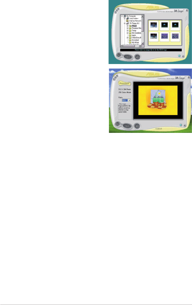
4-10 Chapter 4: Software support
9. When the screen returns to the ASUS Update utility, ash the original BIOS to
load the new boot logo.
10. After ashing the BIOS, restart the computer to display the new boot logo
during POST.
8. Adjust the boot image to your desired
size by selecting a value on the Ratio
box.
7. When the logo images appear on the
right window pane, select an image to
enlarge by clicking on it.
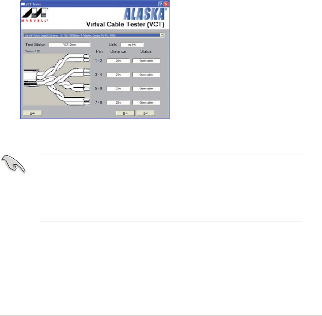
ASUS P6T Deluxe V2 4-11
3. Click the Run button to perform a cable test.
4.3.2 AI NET2
The AI NET2 features the Marvell® Virtual Cable Tester™ (VCT). VCT is a cable
diagnostic utility that reports LAN cable faults and shorts using the Time Domain
Reectometry (TDR) technology. The VCT detects and reports open and shorted
cables, impedance mismatches, pair swaps, pair polarity problems, and pair skew
problems of up to 64 ns at one meter accuracy.
The VCT feature reduces networking and support costs through a highly
manageable and controlled network system. This utility can be incorporated
in the network systems sofware for ideal eld support as well as development
diagnostics.
Using the Virtual Cable Tester™
To use the the Marvell® Virtual Cable Tester™ utility:
1. Launch the VCT utility from the Windows® desktop by clicking Start > All
Programs > Marvell > Virtual Cable Tester.
2. Click Virtual Cable Tester from the menu to display the screen below.
• The VCT utility only tests Ethernet cables connected to Gigabit LAN port(s).
• The Run button on the Virtual Cable Tester™ main window is disabled if no
problem is detected on the LAN cable(s) connected to the LAN port(s).
• If you want the system to check the status of the LAN cable before entering
the OS, enable the item Post Check LAN Cable in the BIOS Setup.
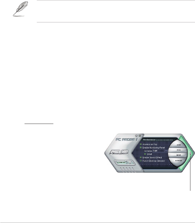
4-12 Chapter 4: Software support
4.3.3 ASUS PC Probe II
PC Probe II is a utility that monitors the computer’s vital components, and detects
and alerts you of any problem with these components. PC Probe II senses fan
rotations, CPU temperature, and system voltages, among others. Because PC
Probe II is software-based, you can start monitoring your computer the moment
you turn it on. With this utility, you are assured that your computer is always at a
healthy operating condition.
Installing PC Probe II
To install PC Probe II on your computer:
1. Place the support DVD to the optical drive. The Drivers installation tab
appears if your computer has an enabled Autorun feature.
If Autorun is not enabled in your computer, browse the contents of the support
DVD to locate the setup.exe le from the ASUS PC Probe II folder. Double-click
the setup.exe le to start installation.
2. Click the Utilities tab, then click ASUS PC Probe II.
3. Follow the screen instructions to complete installation.
Launching PC Probe II
You can launch the PC Probe II right after installation or anytime from the
Windows® desktop.
To launch the PC Probe II from the Windows® desktop, click Start > All Programs
> ASUS > PC Probe II > PC Probe II v1.xx.xx. The PC Probe II main window
appears.
After launching the application, the PC Probe II icon appears in the Windows®
taskbar. Click this icon to close or restore the application.
Using PC Probe II
Main window
The PC Probe II main window allows you to view the current status of your
system and change the utility
conguration. By default, the main
window displays the Preference
section. You can close or restore
the Preference section by clicking
on the triangle on the main
window right handle.
Click to close the
Preference panel
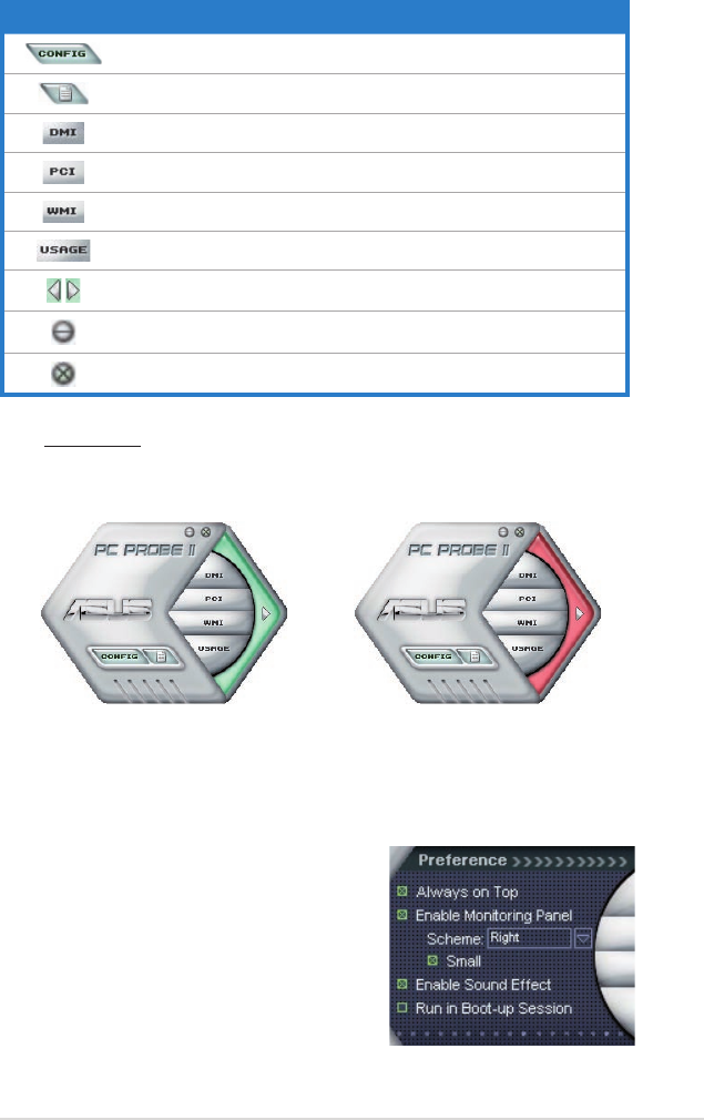
ASUS P6T Deluxe V2 4-13
Sensor alert
When a system sensor detects a problem, the main window right handle
turns red, as the illustrations below show.
When displayed, the monitor panel for that sensor also turns red. Refer to the
Monitor panels section for details.
Preference
You can customize the application using
the Preference section in the main window.
Click the box before each preference to
activate or deactivate.
Button Function
Opens the Conguration window
Opens the Report window
Opens the Desktop Management Interface window
Opens the Peripheral Component Interconnect window
Opens the Windows Management Instrumentation window
Opens the hard disk drive, memory, CPU usage window
Shows/Hides the Preference section
Minimizes the application
Closes the application
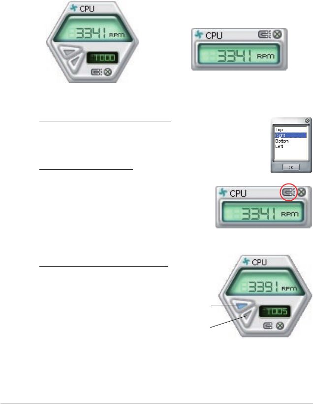
4-14 Chapter 4: Software support
Changing the monitor panels position
To change the position of the monitor panels in the desktop,
click the arrow down button of the Scheme options, then select
another position from the list box. Click OK when nished.
Moving the monitor panels
All monitor panels move together using a magnetic effect. If
you want to detach a monitor panel from
the group, click the horseshoe magnet
icon. You can now move or reposition the
panel independently.
Hardware monitor panels
The hardware monitor panels display the current value of a system sensor such as
fan rotation, CPU temperature, and voltages.
The hardware monitor panels come in two display modes: hexagonal (large) and
rectangular (small). When you check the Enable Monitoring Panel option from the
Preference section, the monitor panels appear on your computer’s desktop.
Large display
Small display
Click to
increase
value
Click to
decrease
value
Adjusting the sensor threshold value
You can adjust the sensor threshold
value in the monitor panel by
clicking the or buttons. You can
also adjust the threshold values
using the Cong window.
You cannot adjust the sensor
threshold values in a small
monitoring panel.
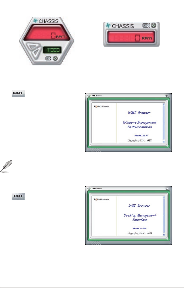
ASUS P6T Deluxe V2 4-15
Monitoring sensor alert
The monitor panel turns red when a component value exceeds or is lower
than the threshold value. Refer to the illustrations below.
Large display
Small display
WMI browser
Click to display the
WMI (Windows Management
Instrumentation) browser. This
browser displays various Windows®
management information. Click an
item from the left panel to display on
the right panel. Click the plus sign (+)
before WMI Information to display the
available information.
You can enlarge or reduce the browser size by dragging the bottom right corner
of the browser.
DMI browser
Click to display the DMI
(Desktop Management Interface)
browser. This browser displays various
desktop and system information.
Click the plus sign (+) before DMI
Information to display the available
information.
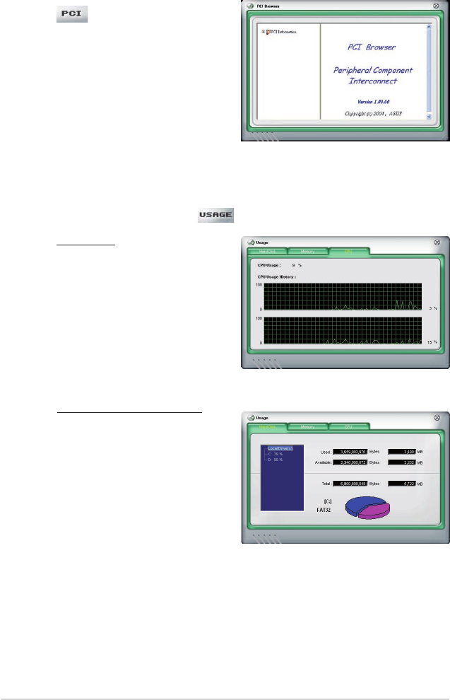
4-16 Chapter 4: Software support
PCI browser
Click to display the PCI
(Peripheral Component Interconnect)
browser. This browser provides
information on the PCI devices installed
on your system. Click the plus sign
(+) before the PCI Information item to
display available information.
Usage
The Usage browser displays real-time information on the CPU, hard disk drive
space, and memory usage. Click to display the Usage browser.
CPU usage
The CPU tab displays real-
time CPU usage in line graph
representation. If the CPU has
an enabled Hyper-Threading,
two separate line graphs display
the operation of the two logical
processors.
Hard disk drive space usage
The Hard Disk tab displays the
used and available hard disk
drive space. The left panel of the
tab lists all logical drives. Click
a hard disk drive to display the
information on the right panel.
The pie chart at the bottom of the
window represents the used (blue)
and the available HDD space.
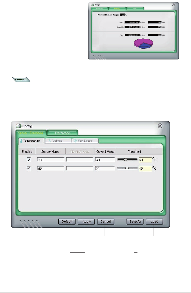
ASUS P6T Deluxe V2 4-17
Memory usage
The Memory tab shows both
used and available physical
memory. The pie chart at the
bottom of the window represents
the used (blue) and the available
physical memory.
Conguring PC Probe II
Click to view and adjust the sensor threshold values.
The Cong window has two tabs: Sensor/Threshold and Preference. The Sensor/
Threshold tab enables you to activate the sensors or to adjust the sensor threshold
values. The Preference tab allows you to customize sensor alerts, or change the
temperature scale.
Loads the default
threshold values for
each sensor
Applies your
changes
Cancels or
ignores your
changes
Loads your saved
conguration
Saves your
conguration
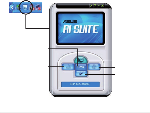
4-18 Chapter 4: Software support
4.3.4 ASUS AI Suite
ASUS AI Suite allows you to launch EPU—6 Engine, AI Nap, Fan Xpert, and
TurboV utilities easily.
Installing AI Suite
To install AI Suite on your computer:
1. Place the support DVD to the optical drive. The Drivers installation tab
appears if your computer has an enabled Autorun feature.
2. Click the Utilities tab, then click AI Suite.
3. Follow the screen instructions to complete installation.
Launching AI Suite
You can launch AI Suite right after installation or anytime from the Windows®
desktop.
To launch AI Suite from the Windows® desktop, click Start > All Programs >
ASUS > AI Suite > AI Suite v1.xx.xx. The AI Suite main window appears.
After launching the application, the AI Suite icon appears in the Windows® taskbar.
Click this icon to close or restore the application.
Using AI Suite
Click the EPU—6 Engine, AI Nap, or Fan Xpert icon to launch the utility, or click
the Normal icon to restore the system to normal state.
Press to launch AI Nap
Press to launch
Fan Xpert
Press to restore to
normal state
Press to launch
EPU—6 Engine
Press to launch
TurboV
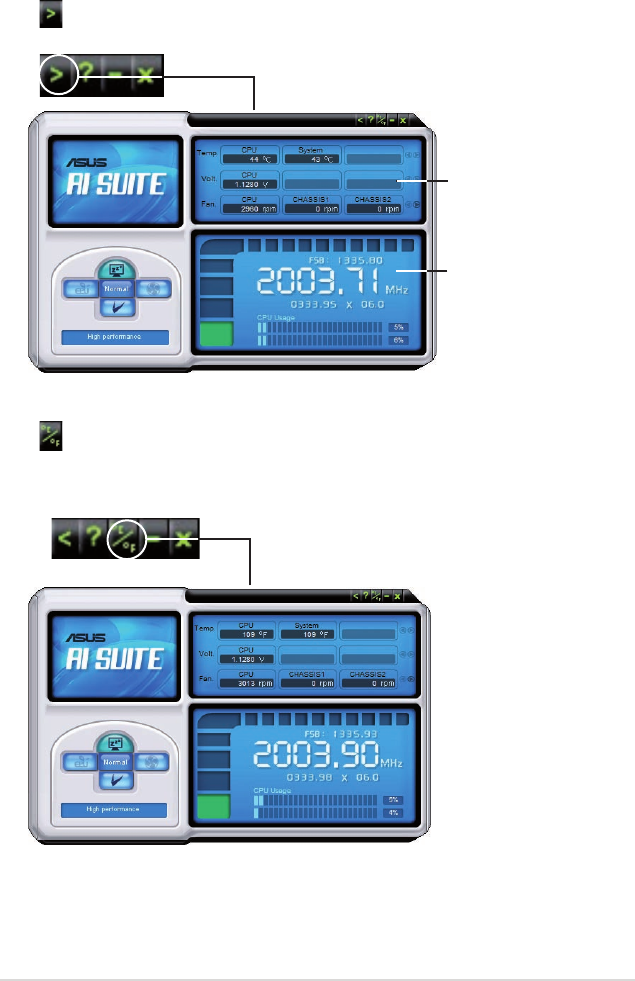
ASUS P6T Deluxe V2 4-19
Other feature buttons
Click on right corner of the main window to open the monitor window.
Click on right corner of the expanded window to switch the temperature from
degrees Centigrade to degrees Fahrenheit.
Displays the CPU/
system temperature,
CPU/memory/PCIE
voltage, and CPU/
chassis fan speed
Displays the FSB/CPU
frequency
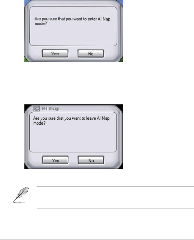
4-20 Chapter 4: Software support
4.3.5 ASUS AI Nap
This feature allows you to minimize the power consumption of your computer
whenever you are away. Enable this feature for minimum power consumption and
a more quiet system operation.
After installing AI Suite from the bundled support DVD, you can launch the utility by
double-clicking the AI Suite icon on the Windows OS taskbar and click the AI Nap
button on the AI Suite main window.
Click Yes on the conrmation screen.
To exit AI Nap mode, press the system power or mouse button then click Yes on
the conrmation screen.
To switch the power button functions from AI Nap to shutting down, just right
click the AI Suite icon on the OS taskbar, select AI Nap and click Use power
button. Unclick the the item to switch the function back.
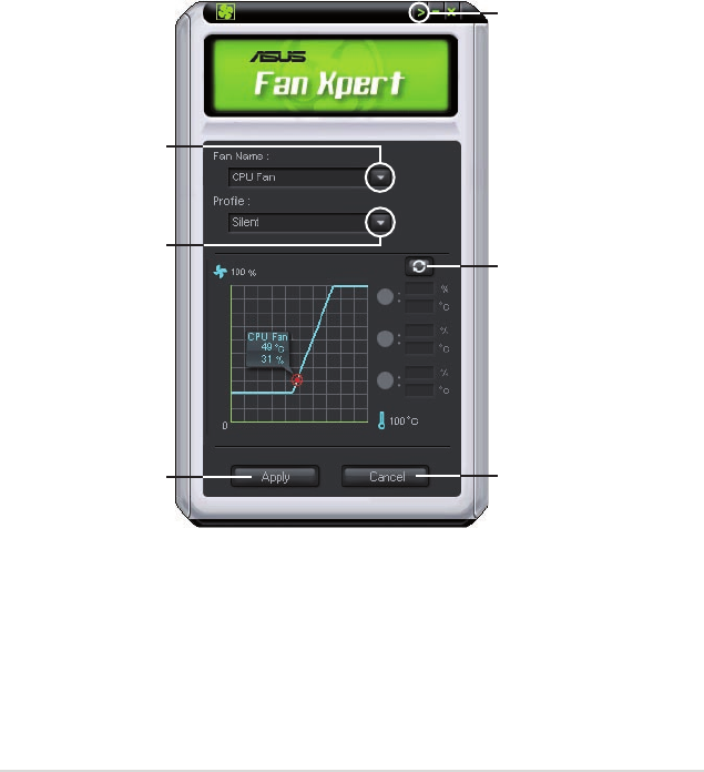
ASUS P6T Deluxe V2 4-21
4.3.6 ASUS Fan Xpert
Asus Fan Xpert intelligently allows you to adjust both the CPU and chassis fan
speeds according to different ambient temperatures caused by different climate
conditions in different geographic regions and your PC’s system loading. The
built-in variety of useful proles offer exible controls of fan speed to achieve a
quiet and cool environment.
Install AI Suite from the bundled support DVD. To launch the ASUS Fan Xpert
utility, double-click the AI Suite icon on the Windows® notication bar and click
the Fan Xpert button on the AI Suite main window.
Click the dropdown list button and display the fan types. Select CPU Fan or
Chassis Fan.
Dropdown list button
Click to display
the dropdown list
and select a fan
prole mode
Click to display
the current CPU
temperature and the
fan speed ratio
Click to save the setup Click to cancel the
Fan Xpert utility
Click to open the
Calibration wiondow
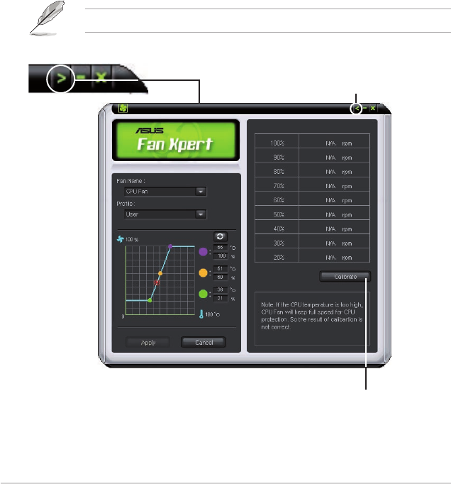
4-22 Chapter 4: Software support
Click to get the calibration between
the fan rotation and fan speed ratio
Click to close the Calibration window
Fan prole modes
• Disable: Select this mode to disable the Fan Xpert function.
• Standard: This mode makes the fan adjust speed in moderate pattern.
• Silent: This mode minimizes fan speed for quiet fan operation.
• Turbo: This mode boosts the fan to achieve maximal fan speed for the best
cooling effect.
• Intelligent: This mode automatically adjusts the CPU fan speed with the
ambient temperature.
• Stable: This mode keeps the CPU fan at the same speed to avoid noise
caused by the unsteady fan rotation. However, the fan will speed up
when the temperature exceeds 70ºC.
• User: This mode allows you to change the CPU fan prole under certain
limitation.
For Chassis Fan, only Disable/Standard/Silent/Turbo modes could be selected.
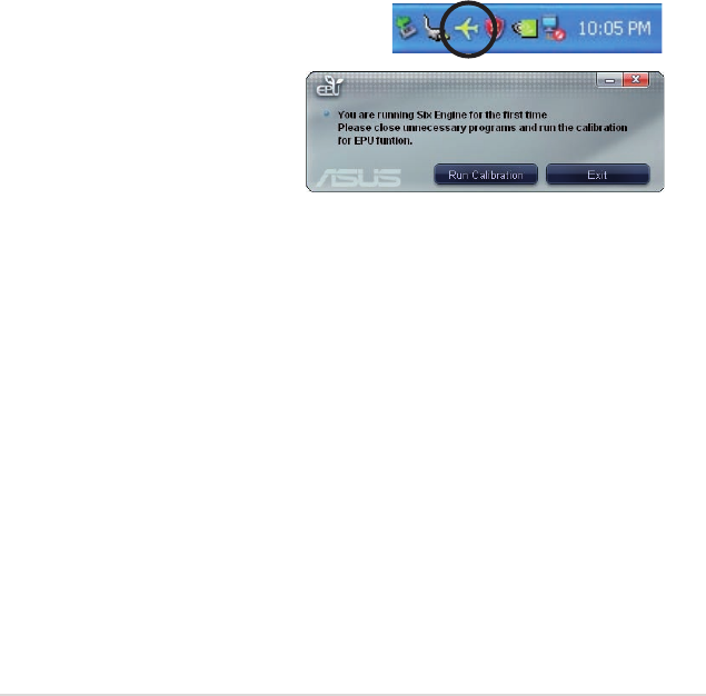
ASUS P6T Deluxe V2 4-23
4.3.7 ASUS EPU–6 Engine
ASUS EPU–6 Engine is an energy-efcient tool that satises different computing
needs. This utility provides four modes that you can select to enhance system
performance or save power. Selecting Auto mode will have the system shift modes
automatically according to current system status. You can also customize each
mode by conguring settings like CPU frequency, vCore Voltage, and Fan Control.
Installing 6 Engine
To install 6 Engine on your computer:
1. Place the support DVD to the optical drive. The Drivers installation tab
appears if your computer has an enabled Autorun feature.
2. Click the Drivers tab and then click ASUS EPU—6 Engine.
3. Follow the screen instructions to complete installation.
Launching 6 Engine
Launch 6 Engine by double-clicking the 6 Engine icon on the Windows® notication
area.
The rst time you launch 6 Engine, the following
message will appear, asking you
to run Calibration rst. Running
calibration allows the system to
detect CPU properties to optimize
power management.
Click Run Calibration and wait for a few seconds. Then, the 6 Engine main menu
appears.
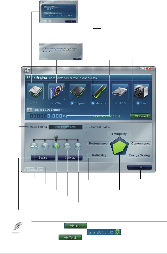
4-24 Chapter 4: Software support
*• Click Current to show the CO2 that has been reduced since
you click the Renew button .
*• Click Total to show the total CO2 that has been reduced
since you launched 6 Engine.
6 Engine main menu
Auto Mode Runs calibration
Turbo Mode
High Performance Mode
Medium Power Saving Mode
Max. Power Saving Mode
Advanced settings for each mode (refer to the next page for further information)
Displays CPU Power and
Total CPU Energy Saving
*Shifts between
the display of Total
and Current CO2
reduced
Displays the
amount of CO2
reduced
Displays the following
message if no VGA power
saving engine is detected.
Exits the utility
Displays the system
properties of each
mode
Displays
current
mode
Lights up when power
saving engine is activated
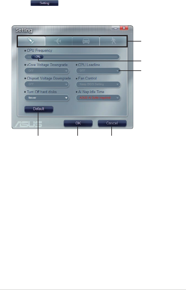
ASUS P6T Deluxe V2 4-25
Click to select
a mode
Move the
slider to adjust
Click the arrow
to see more
options
Restore default
settings
Click to apply
settings
Click to abort
settings
Conguration options in Advanced settings menu
The following lists the conguration options and their denitions in Advanced
settings menu.
• CPU Frequency: Raises or lowers CPU frequency to a certain percentage.
• vCore Voltage Downgrade: Lowers CPU vCore voltage.
• High: Downgrades voltage to the highest level for CPU power saving.
• Small: Downgrades voltage to the minimum level.
• Chipset Voltage Downgrade: Turns on/off chipset voltage.
• Turn Off hard disks: Turns off hard disk drives when they are not accessed
after a certain time.
• CPU Loadline: Sets up the CPU loadline to manage CPU power saving.
• Light: Saves CPU power to the minimum level.
• Heavy: Saves CPU power to the highest level.
Advanced settings menu
Click Setting ( ) from the 6 Engine main menu to display conguration
options in each mode. Some options in certain modes are dimmed, meaning that
they are not available.

4-26 Chapter 4: Software support
Conguration
options
Turbo Mode High
Performance
Mode
Medium Power
Saving Mode
Maximum
Power Saving
Mode
CPU
Frequency
Overclocking
+1% to +30%
N/A Downclocking
-1% to -50%
Downclocking
-1% to -50%
vCore Voltage
Downgrade
N/A N/A Small/High Small/High
Chipset
Voltage
Downgrade
N/A N/A On/Off On/Off
Turn Off
hard disks
Never/After 3
mins–After 5
hours
Never/After 3
mins–After 5
hours
Never/After 3
mins–After 5
hours
Never/After 3
mins–After 5
hours
CPU Loadline N/A N/A Light/Heavy Light/Heavy
Fan Control N/A N/A Keep Bios
Setting/Slow
Keep Bios
Setting/Quiet
AI Nap
Idle Time
Never/After 3
mins–After 5
hours
Never/After 3
mins–After 5
hours
Never/After 3
mins–After 5
hours
Never/After 3
mins–After 5
hours
Refer to the following table for the conguration options in each mode.
• Fan Control: Adjusts fan speeds to reduce noise and save system power.
• Quiet: Lowers CPU fan speed and shuts off two chassis fans.
• Slow: Lowers CPU fan and two chassis fan speeds.
• AI Nap Idle Time: Enters AI Nap mode after a certain time during system idle
process.
The values of the previous table are subject to change at any time without
notice. Visit the ASUS website (www.asus.com) for updates.
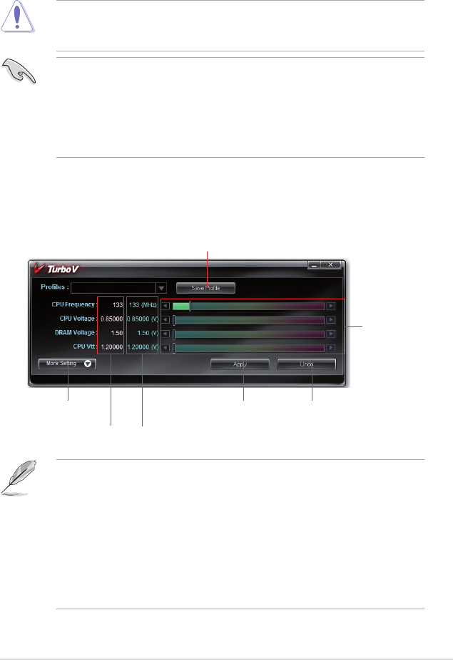
ASUS P6T Deluxe V2 4-27
4.3.8 ASUS TurboV
ASUS TurboV allows you to overclock the CPU frequency, CPU voltage, QPI/
Memory controller voltage, and DRAM voltage in WIndows® environment and takes
effect in real-time without exiting and rebooting the OS.
Refer to the CPU documentation before adjusting CPU voltage settings. Setting
a high voltage may damage the CPU permanently, and setting a low voltage
may make the system unstable.
• For system stability, all changes made in ASUS TurboV will not be saved
to BIOS settings and will not be kept on the next system boot. Use the
Save Prole function to save your customized overclocking settings and
manually load the prole after Windows starts.
• For system stability, set ASUS EPU 6-Engine to High Performance Mode
while using ASUS TurboV.
To launch ASUS TurboV
1. Install the ASUS TurboV utility from the motherboard support DVD.
2. Click start > All Programs > ASUS > TurboV > TurboV.
Save the current settings as a prole
Shows more
settings
Applies all
changes
immediately
Undoes all
changes
without
applying
Voltage
Adjustment
bars
Default
settings
Target
settings
Overclocking tips:
• For advanced overclockability, adjust rst the Ai Tweaker items in BIOS,
and then proceed more detailed adjustments using TurboV.
• The BCLK Frequency setting in BIOS affects the adjustable range of CPU
Frequency in TurboV.
For advanced overclocking:
Set BCLK Frequency in BIOS to 200MHz or
above for an adjustment range from 200MHz to 500MHz in TurboV.
For general overclocking:
Set BCLK Frequency in BIOS below 200MHz for
an adjustment range from 100MHz to 250MHz in TurboV.
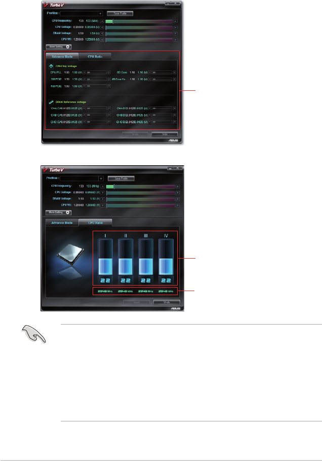
4-28 Chapter 4: Software support
Advanced settings menu
Click More Setting from the TurboV main screen to display detailed conguration
options for CPU/chip voltage, DRAM Reference voltage, and CPU ratio.
• Only Intel® Core™ i7 Extreme Edition processors support the CPU Ratio
function.
• Set the CPU Ratio Setting BIOS item to [Auto] before using the CPU Ratio
function in TurboV. See page 3-26 for details.
• The value shown in CPU Ratio Mode may be higher than your CPU default
setting. This is due to Intel’s Dynamic Speed Technology of automatic CPU
ratio overclocking. You may turn off this feature in BIOS for manual CPU
ratio adjustment. See page 3-27 for details.
Advanced
CPU and
DRAM voltage
settings
Advance Mode
Adjusts CPU
core ratio
Displays CPU
frequency
CPU Ratio Mode
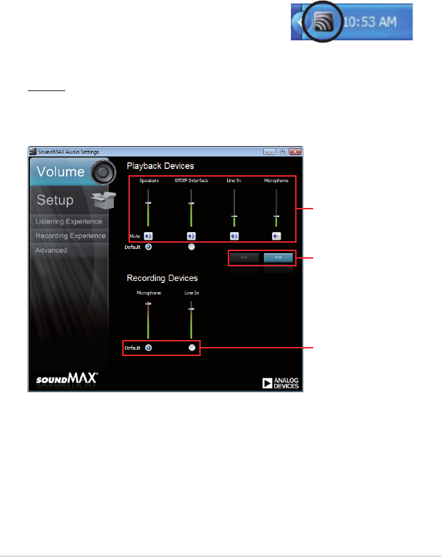
ASUS P6T Deluxe V2 4-29
4.3.9 SoundMAX® High Denition Audio utility
The ADI AD2000B High Denition Audio CODEC provides 8-channel audio
capability through the SoundMAX® audio utility with AudioESP™ software to
deliver the ultimate audio experience on your PC. The software implements high
quality audio synthesis/rendering, 3D sound positioning, and advanced voice-input
technologies.
Follow the installation wizard to install the ADI AD2000B Audio Driver from the
support DVD that comes with the motherboard package to activate the
SoundMAX® audio utility.
If the SoundMAX® audio utility is correctly installed, you
will nd the SoundMAX® icon on the taskbar.
A. SoundMAX audio utility for Windows Vista™
Volume
The Volume tab allows you to adjust the individual volume of playback and
recording devices. You can also set the default audio output and input device
in this tab.
Click to
show more
devices
Drag to
adjust
device
volume
Click to set
the default
device
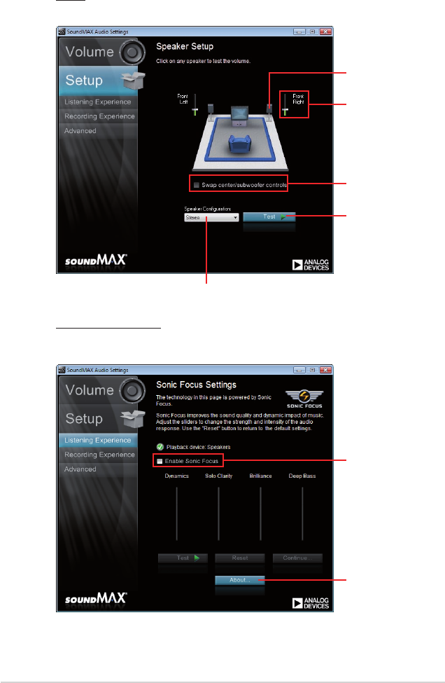
4-30 Chapter 4: Software support
Setup
The Setup tab allows you to adjust multi-speaker settings.
Click speaker to
test individual
speaker volume
Click to swap
center/subwoofer
output in 5.1 / 7.1
Surround mode
Click to test
the volume of
all individual
speakers
Click to choose a multi-speaker conguration
Drag slider to adjust
individual speaker
volume
Listening Experience
The Listening Experience tab allows you to enable or disable the Sonic
Focus sound effects and adjust further sound settings.
Click to enable
Sonic Focus
Click to
show license
information of
Sonic Focus
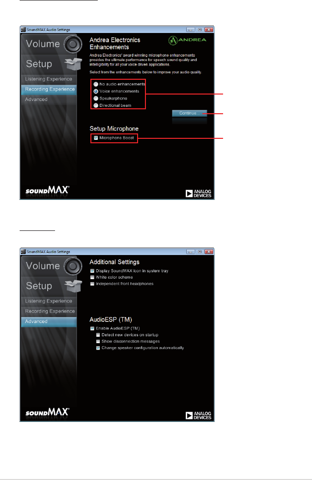
ASUS P6T Deluxe V2 4-31
Recording Experience
The Recording Experience tab allows you to calibrate microphone settings
for high quality recording effects.
Advanced
The Advanced tab allows you to congure detailed utility settings.
Choose a desired
enhancement
Click to start
microphone
calibration
Click to boost
microphone
volume
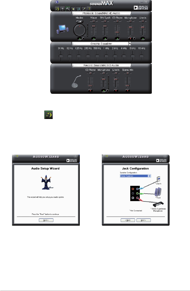
4-32 Chapter 4: Software support
Jack conguration
This screen helps you congure your
computer’s audio ports, depending on
the audio devices you have installed.
B. SoundMAX audio utility for Windows XP™
Audio Setup Wizard
By clicking the icon from the
SoundMAX® control panel, you can
easily congure your audio settings.
Simply follow the succeeding screen
instructions and begin enjoying High
Denition Audio.
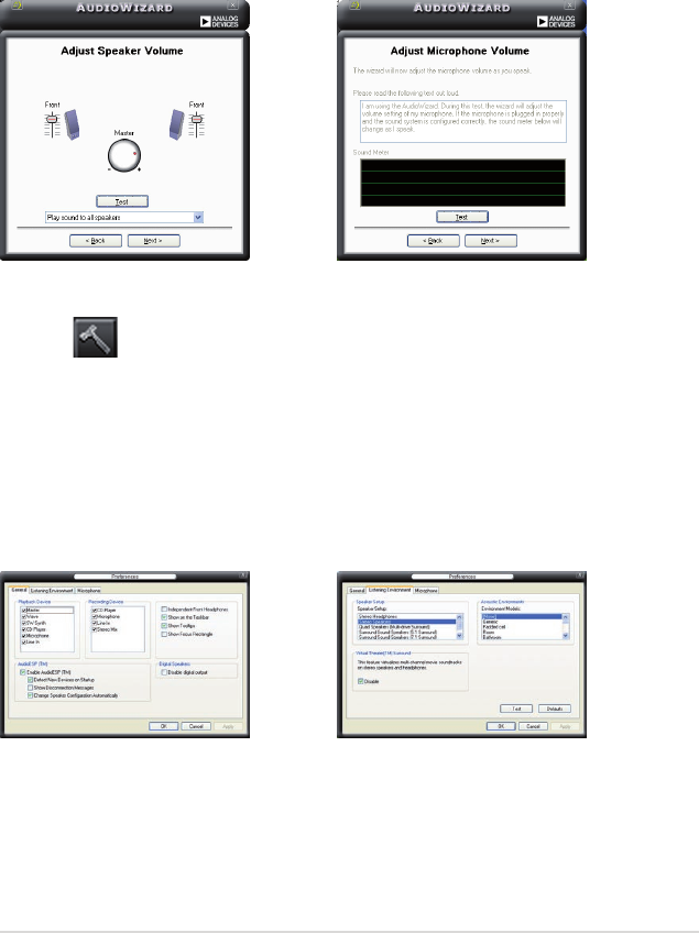
ASUS P6T Deluxe V2 4-33
Adjust speaker volume
This screen helps you adjust speaker
volume. Click the Test button to hear
the changes you have made.
Adjust microphone volume
This screen helps you adjust
microphone volume. You will be asked
to read pre-written text to allow the
AudioWizard to adjust the volume as
you speak.
General options
Click the General tab to choose your
playback and recording devices,
enable/disable the AudioESP™
feature, and enable/disable digital
output.
Audio preferences
Click the icon to go to the Preferences page. This page allows you to change
various audio settings.
Listening Environment options
Click the Listening Environment tab
to set up your speaker, acoustic
environment, and enable/disable the
Virtual Theater Surround function.
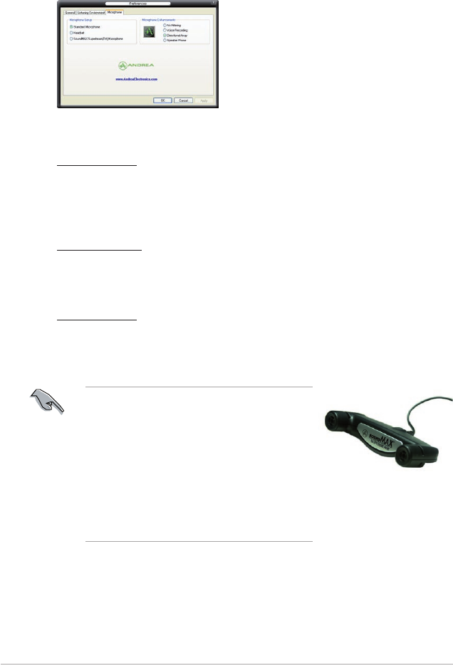
4-34 Chapter 4: Software support
Microphone options
Click the Microphone tab allows you to optimize your microphone input settings.
Enhanced Microphone Features
Voice recording
Enables Noise Filter function. Detects repetitive and stationary noises like
computer fans, air conditioners, and other background noises then eliminates
it in the incoming sudio stream while recording. You can enable it for a better
recording quality.
Directional Array
Receives only the sound coming from the reception cone and eliminates
interferences including neighboring speakers and reverberations. You can
enable it to transit clearer sound during on-line games, MSN, or Skype.
Speaker Phone
Advanced de-reverberation techniques can help to reduce echo and minimize
its effect on the speech engine. You can enable it when you have conference
call to reduce echoes in the other side.
• The directional Array and Speaker Phone
are purchased separately and function only
when working with the ASUS Array Mic.
• If you are using Windows Vista, you have to
manually enable the directional Array and
Speaker Phone function. Go to Control
panel > Sound. Click the Recording tab on
the top and select Microphone. Click the
Microphone Enhancement tab and check
Directional beam.
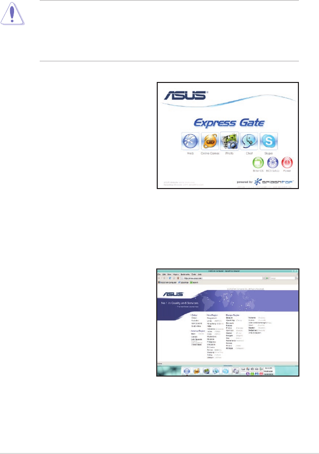
ASUS P6T Deluxe V2 4-35
4.3.10 ASUS Express Gate SSD
ASUS Express Gate SSD is an instant-on environment that gives you quick access
to web, Skype, and viewing your pictures. Within a few seconds of powering on
your computer, you will be at the Express Gate SSD menu where you can start the
web browser, Skype, or other Express Gate applications.
• ASUS Express Gate supports SATA devices in IDE or SATA mode only.
• ASUS Express Gate supports HDDs or ODDs connected to motherboard
chipset-controlled onboard SATA ports only. All onboard extended SATA
ports and external SATA ports are NOT supported. See chapter 2 for the
exact location of onboard SATA ports.
The First Screen
Express Gate SSD’s rst screen appears
within a few seconds after you power
on the computer. From here, you can
immediately start the web browser or
Skype.
You can also choose to continue booting
normally (e.g. to your installed OS such
as Windows), enter BIOS setup, or power
off.
If you don’t make any selection, Express
Gate SSD will automatically exit and boot to your normal OS after a certain amount
of time. The timer countdown is shown on-screen inside the “boot to OS” button. As
you move the mouse or type a key, the countdown stops and the timer disappears,
so you can take your time to make a selection.
The Express Gate SSD Environment
The very rst time you enter the Express
Gate SSD environment (by launching
either web or Skype from the rst
screen), a rst time wizard will guide
you through basic Express Gate SSD
congurations. Basic congurations
include language, date and time and
screen resolution.
4-36 Chapter 4: Software support
Knowing the Express Gate hot-keys
Here is a list of common-used hot-keys for Express Gate.
In the First Screen:
Key Function
PAUSE/BREAK Power-off
ESC/F8 Continue to boot OS
DEL Enter BIOS setup
In the Express Gate Environment:
Key Function
<Alt> + <Tab> Switch between softwares
<Ctrl> + <Alt> + <Del> Bring up Power-Off dialog box
<Ctrl> + <Alt> + <Print Screen> Save screen snapshot as picture to le
Once inside the Express Gate SSD environment, click on the icons on the
LaunchBar, by default at bottom of the screen, to launch or switch between
softwares. You can re-arrange, re-size and move windows. Bring a window to the
foreground by clicking within it or by clicking on its corresponding software icon.
Re-size a window by dragging any of its four corners. Move a window by dragging
its title bar.
Besides using the LaunchBar, you can also switch between softwares by pressing
<Alt> +<Tab> on the keyboard. You can also right-click anywhere on the desktop to
bring up a menu of softwares.
The red triangle on an software icon in the LaunchBar denotes that the software is
already running. This means that you can switch to it without any delay. In the rare
case where an software stops responding, right-click on its icon to force close it.
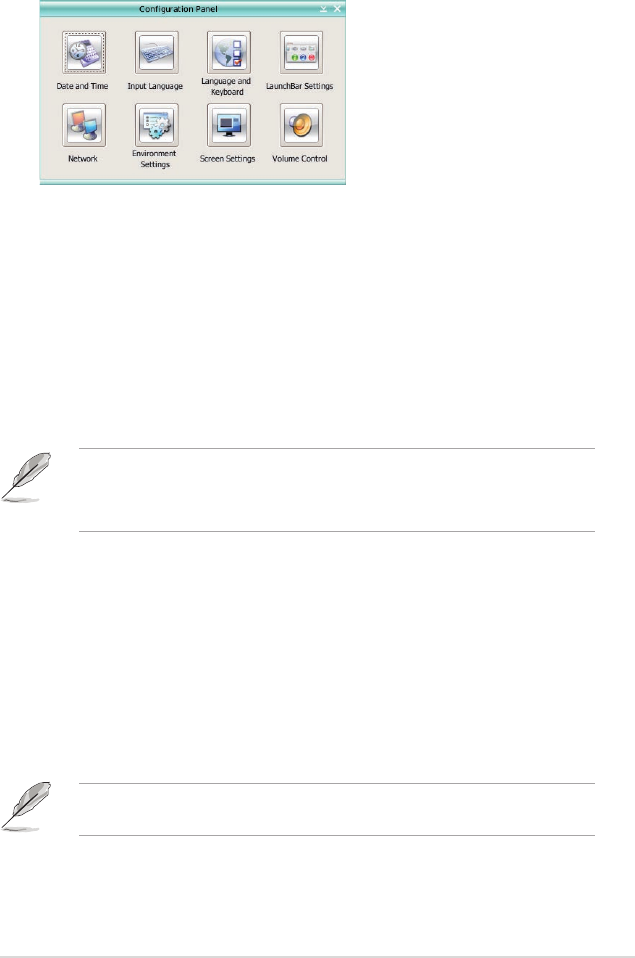
ASUS P6T Deluxe V2 4-37
Using the Conguration Panel
Use the conguration panel to change various Express Gate SSD settings.
Click on an icon to open a particular conguration tool. The following tools are
available:
• Date and Time: set current date and time as well as time zone.
• Input Language: choose your preferred input language and method.
• Language and Keyboard: choose your language and keyboard preferences.
• LaunchBar Settings: customize your LaunchBar (where it docks, whether it
auto-hides, etc.)
• Network: Specify how your computer connects to the Internet. Enable all the
network ports that you may use. LAN(s) refer to the RJ-45 network port(s) on
your computer.
• The number of the LAN ports may differ from motherboards.
• You can connect the LAN cable to any RJ-45 port, and Express Gate SSD
will automatically use the connected port.
Also specify whether each port uses DHCP (most common) or static IP. For
PPPoE and wireless (optional), set the login credentials (user name, password,
SSID, etc.) as well.
• Environment Settings: This function allows you to clear the Express Gate
SSD settings, as well as any personal information stored by the web browser
(Bookmarks, Cookies, History, etc.). The user data will be reset to the original
default conguration.
After you click Restore System, a conrmation dialog box will open. If you
click “Yes” in the conrmation dialog box, your system will immediately restart
and then re-enter Express Gate SSD to nish clearing the settings. This is also
useful in the rare case where settings might become corrupted.
The rst-time Wizard will run again when you enter the Express Gate SSD
environment after clearing its settings.
• Screen Settings: Choose the most optimal screen resolution for your display.
• Volume Control: Control the volume for your speaker output, microphone
input, etc.
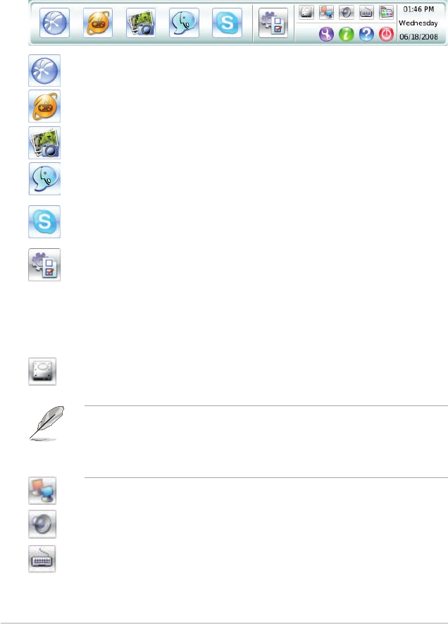
4-38 Chapter 4: Software support
Using the LaunchBar
The LaunchBar has several system icons that show you various system statuses
and let you congure individual Express Gate SSD settings. The LaunchBar can
be congured to auto-hide, if you want more screen space for the softwares. It can
also be congured to dock on any of the four sides of the screen.
Starts the Web Browser for quick access to the World Wide Web.
Accesses the Online Games feature of Express Gate SSD.
Starts the Photo Manager album / organizer tool.
Starts the Chat instant messaging tool.
Start the Skype software, which lets you call other people on Skype
for free, as well as offering affordable, high quality voice communications
to phones all over the world.
Opens Conguration Panel, which lets you specify network settings
and other preferences.
In the rare case that one of the above softwares stops responding, you can right-
click on its icon and then select Close to force it to close.
The smaller icons on the right side of the LaunchBar are:
Click on this icon to open the File Manager window, which lets you
conveniently access the les on a USB drive. If a USB device is
detected, the icon contains a green arrow.
• ASUS Express Gate supports le uploading and downloading from USB
drives only.
• Only the image les in JPG, BMP, GIF, and PNG formats can be uploaded
from SATA HDDs, ODDs and USB drives.
Shows network status; click to congure network.
Shows mute status; click to change volume.
Click to choose input language and method as well as keyboard
shortcuts (Ctrl-Space by default).
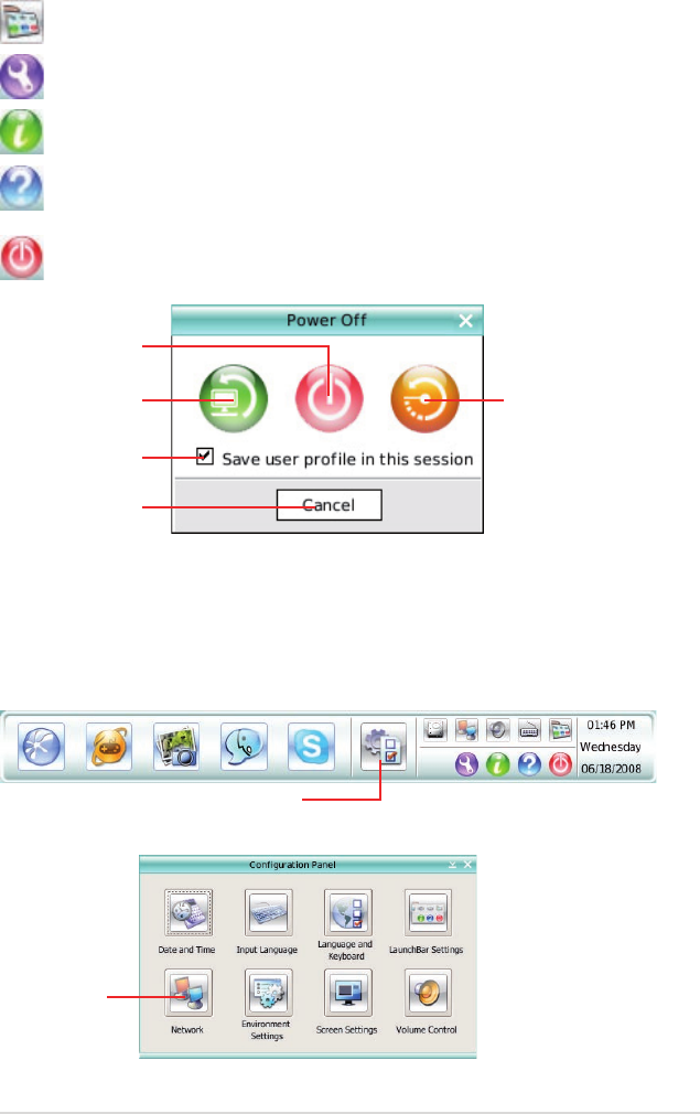
ASUS P6T Deluxe V2 4-39
Click to change LaunchBar options (auto-hide, docking position, etc).
Click to show the “ASUS Utility” panel (if supported).
Click to show “About Express Gate SSD”.
Click to open Express Gate SSD Help.
Click to bring up power options window to boot to OS, restart or power
down. This window is also shown when you press Ctrl-Alt-Del on the
keyboard.
Power off
Enter OS
Cancel and return to
Express Gate SSD
Restart
Check to save
user prole
Open Conguration Panel
How Do I Get on to the Internet
If Internet doesn’t seem to be working in the Express Gate SSD environment,
check the following:
1. Open the Conguration Panel.
2. Open Network.
Network
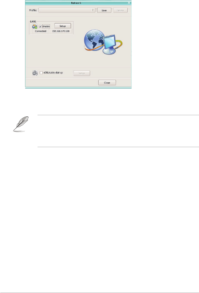
4-40 Chapter 4: Software support
• If you use a network cable connected to a home router (which is then
connected to your DSL/cable modem), enable every LAN port(s). Express
Gate SSD will automatically use whichever port is connected.
• The number of the LAN ports may differ from motherboards.
• If you plug the network cable into a different port while Express Gate SSD
is running (e.g. move the cable from LAN1 to LAN2), you may need to
restart Express Gate SSD in order for it to detect the change.
• The most common scenario is for your computer to automatically obtain
network settings (i.e. DHCP). If this is the case, you don’t need to click Setup
for any LAN port. If this is not the case, click Setup to congure the static IP
settings manually.
• If you have wireless network, click Setup for the WiFi option. In the WiFi tab of
the Advanced Network Settings box, enter the name of your wireless access
point in the SSID eld. If your wireless access point has security enabled,
select the corresponding security algorithm from the drop-down list (e.g.
WEPAUTO) in the Encryption Type eld, and enter the password.
Click OK to enable WiFi and establish the wireless connection.
• If you use a network cable connected directly to your DSL/cable modem (no
router in between), click Setup for xDSL/cable dial-up. This method is also
referred to as PPPoE. Choose whether the DSL/cable modem is connected
to your computer’s LAN port. Then enter the username and password for your
dial-up account.
Click OK to enable xDSL/cable dial-up and establish the PPPoE connection.
When PPPoE is enabled, the port it uses will automatically be unchecked and
grayed out.
3. Make the proper network congurations.
Each network interface is enabled immediately when you check the box next
to it.
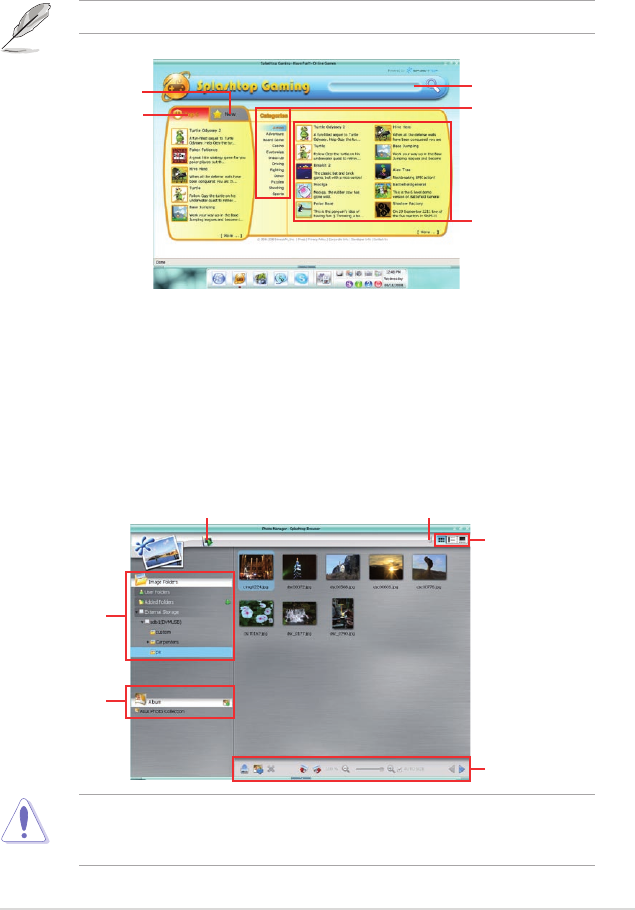
ASUS P6T Deluxe V2 4-41
Using the Photo Manager
Express Gate SSD provides a easy-to-use Photo Manager that allows you to
view pictures stored in your hard drive or external storage devices (such as USB
dongles, card readers, or optical disks). You can view pictures in thumbnail view;
in an enlarged view individually; in a lename/data list view; or play them in a
slideshow with background music and fancy transition effects. JPEG, GIF, BMP,
and PNG formats are supported. Refer to the on-line Help for detailed software
operation.
Shows
the image
folder(s)
found in your
hard drive
or external
devices
Shows user-
created image
album(s)
Image
control bar
View mode
selection
HelpPhoto slideshow
ASUS Express Gate supports HDDs connected to motherboard chipset-
controlled onboard SATA ports only. All onboard extended SATA ports and
external SATA ports are NOT supported.
Using the Online Games
Express Gate SSD introduces a Splashtop Gaming portal site, which provides
many interesting games in different categories. The game titles are updated from
time to time. Enjoying these great games is just as easy as it gets!
You have to enable the network connection to run the Online Games feature.
Search a game
See the most
popular games
See the latest games
See games in
different categories
Game list
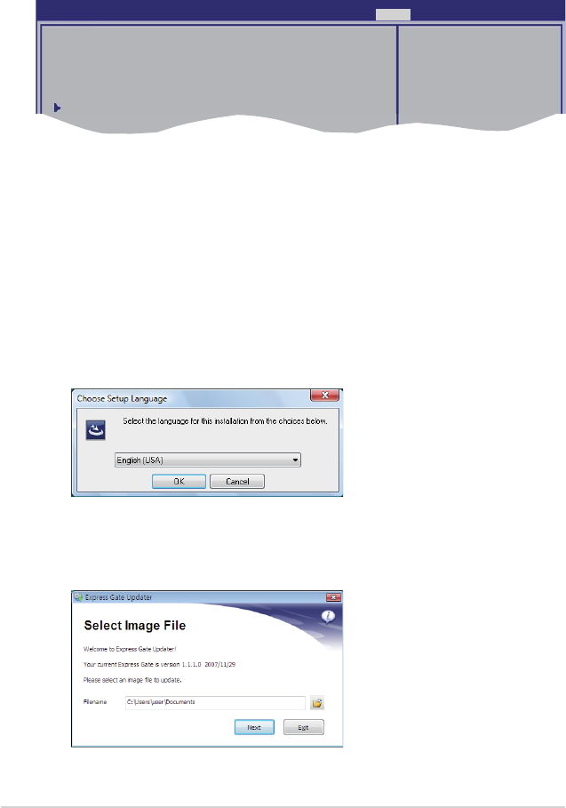
4-42 Chapter 4: Software support
Conguring Express Gate in BIOS Setup
Enter BIOS setup by pressing DEL key after powering on or by clicking on the
BIOS setup icon on Express Gate’s rst screen. Express Gate conguration
options are under Tools conguration menu page. See page 3-41 for details.
ASUS EZ Flash 2
Express Gate [Enabled]
Enter OS Timer [10 Seconds]
Reset User Data [10]
ASUS O.C. Prole
Press ENTER to run
the utility to select
and update BIOS.
This utility doesn't
support :
1.NTFS format
BIOS SETUP UTILITY
Main Ai Tweaker Advanced Power Boot Tools Exit
Express Gate Updater
Use the Express Gate Updater to update your existing Express Gate software to
new versions or to restore the Express Gate software if it is ever corrupted. You
can nd Express Gate Updater Installer on the support DVD or download it from
the ASUS support website. It runs on Windows.
New versions of the Express Gate software will be released regularly, adding
renements or new applications. You can nd original version of the software
on the support DVD or download new versions from the ASUS support website.
Express Gate software is released as an image le with .DFI extension.
To install the Express Gate Updater, launch the installer and follow on-screen
prompts.
To use the Express Gate Updater, launch the application and follow on-screen
prompts.
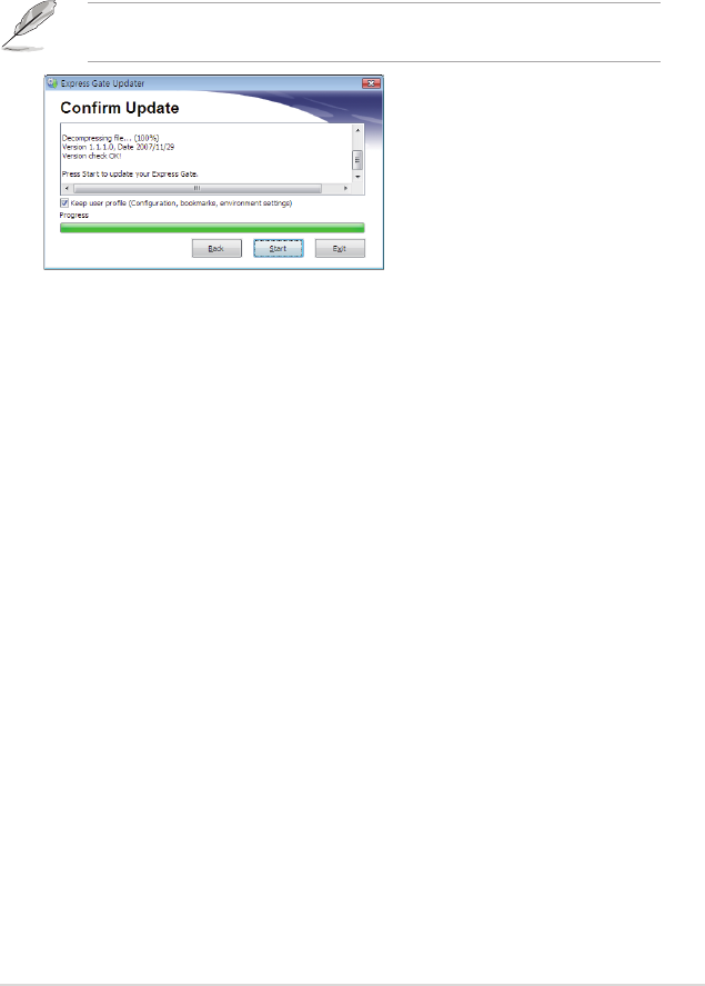
ASUS P6T Deluxe V2 4-43
The Updater can preserve your Express Gate settings and personal data (web
browser bookmarks, etc.) while doing an update. Use the checkbox “Keep user
prole” to decide whether the Updater should do so.
Clearing the user data is useful in the rare case where corrupt settings prevent the
Express Gate environment from launching properly.
The rst time wizard will run again when you enter the Express Gate
environment after clearing its settings.

4-44 Chapter 4: Software support
4.4 RAID congurations
The motherboard comes with the Intel® ICH10R Southbridge controller that
supports RAID 0, RAID 1, RAID 10, and RAID 5 for six independent Serial ATA
channels.
4.4.1 RAID denitions
RAID 0 (Data striping) optimizes two identical hard disk drives to read and write
data in parallel, interleaved stacks. Two hard disks perform the same work as a
single drive but at a sustained data transfer rate, double that of a single disk alone,
thus improving data access and storage. Use of two new identical hard disk drives
is required for this setup.
RAID 1 (Data mirroring) copies and maintains an identical image of data from
one drive to a second drive. If one drive fails, the disk array management software
directs all applications to the surviving drive as it contains a complete copy of
the data in the other drive. This RAID conguration provides data protection and
increases fault tolerance to the entire system. Use two new drives or use an
existing drive and a new drive for this setup. The new drive must be of the same
size or larger than the existing drive.
RAID 5 stripes both data and parity information across three or more hard
disk drives. Among the advantages of RAID 5 conguration include better
HDD performance, fault tolerance, and higher storage capacity. The RAID
5 conguration is best suited for transaction processing, relational database
applications, enterprise resource planning, and other business systems. Use a
minimum of three identical hard disk drives for this setup.
RAID 10 is data striping and data mirroring combined without parity (redundancy
data) having to be calculated and written. With the RAID 10* conguration you get
all the benets of both RAID 0 and RAID 1 congurations. Use four new hard disk
drives or use an existing drive and three new drives for this setup.
Intel® Matrix Storage. The Intel® Matrix Storage technology supported by the
ICH10R chip allows you to create a RAID 0, RAID 1, RAID 5, and RAID 10*
function to improve both system performance and data safety. You can also
combine two RAID sets to get higher performance, capacity, or fault tolerance
provided by the difference RAID function. For example, RAID 0 and RAID 1 set
can be created by using only two identical hard disk drives.
If you want to boot the system from a hard disk drive included in a created RAID
set, copy rst the RAID driver from the support DVD to a oppy disk before you
install an operating system to the selected hard disk drive. Refer to section 4.5
Creating a RAID driver disk for details.

ASUS P6T Deluxe V2 4-45
4.4.3 Intel® RAID congurations
This motherboard supports RAID 0, RAID 1, RAID 5, RAID 10 and Intel® Matrix
Storage congurations for Serial ATA hard disks drives through the Intel® ICH10R
Southbridge chip.
Setting the RAID item in BIOS
You must set the RAID item in the BIOS Setup before you can create a RAID
set(s). To do this:
1. Enter the BIOS Setup during POST.
2. Go to the Main menu, select Storage Conguration, then press <Enter>.
3. Select the item Configure SATA as, then press <Enter> to display the
conguration options.
4. Select [RAID] from the Congure SATA as item options, then press <Enter>.
5. Save your changes, then exit the BIOS Setup.
Refer to the system or the motherboard user guide for details on entering and
navigating through the BIOS Setup.
4.4.2 Installing Serial ATA hard disks
The motherboard supports Serial ATA hard disk drives. For optimal performance,
install identical drives of the same model and capacity when creating a disk array.
To install the SATA hard disks for a RAID conguration:
1. Install the SATA hard disks into the drive bays.
2. Connect the SATA signal cables.
3. Connect a SATA power cable to the power connector on each drive.
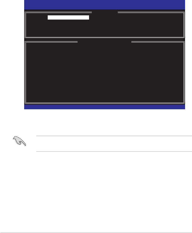
4-46 Chapter 4: Software support
Intel® Matrix Storage Manager option ROM utility
The Intel® Matrix Storage Manager Option ROM utility allows you to create RAID 0,
RAID 1, RAID 10 (RAID 0+1), and RAID 5 set(s) from Serial ATA hard disk drives
that are connected to the Serial ATA connectors supported by the Southbridge.
To enter the Intel® Matrix Storage Manager option ROM utility:
1. Install all the Serial ATA hard disk drives.
2. Turn on the system.
3. During POST, press <Ctrl+I> to display the utility main menu.
Intel(R) Matrix Storage Manager Option ROM v8.0.0.1027 ICH10R wRAID5
Copyright(C) 2003-08 Intel Corporation. All Rights Reserved.
[ MAIN MENU ]
1. Create RAID Volume 3. Reset Disks to Non-RAID
2. Delete RAID Volume 4. Exit
[ DISK/VOLUME INFORMATION ]
RAID Volumes:
None dened.
Physical Disks:
Port Drive Model Serial # Size Type/Status(Vol ID)
0 XXXXXXXXXXX XXXXXXXX XX.XXGB Non-RAID Disk
1 XXXXXXXXXXX XXXXXXXX XX.XXGB Non-RAID Disk
2 XXXXXXXXXXX XXXXXXXX XX.XXGB Non-RAID Disk
3 XXXXXXXXXXX XXXXXXXX XX.XXGB Non-RAID Disk
[↑↓]-Select [ESC]-Exit [ENTER]-Select Menu
The navigation keys at the bottom of the screen allow you to move through
the menus and select the menu options.
The RAID BIOS setup screens shown in this section are for reference only and
may not exactly match the items on your screen.

ASUS P6T Deluxe V2 4-47
Creating a RAID 0 set (striped)
To create a RAID 0 set:
1. From the utility main menu, select 1. Create RAID Volume and press
<Enter>. The following screen appears.
2. Enter a name for the RAID 0 set and press <Enter>.
3. When the RAID Level item is highlighted, press the up/down arrow key to
select RAID 0(Stripe), and then press <Enter>.
4. When the Disks item is highlighted, press <Enter> to select the hard disk
drives to congure as RAID. The following screen appears.
Intel(R) Matrix Storage Manager option ROM v8.0.0.1027 ICH10R wRAID5
Copyright(C) 2003-08 Intel Corporation. All Rights Reserved.
[ CREATE VOLUME MENU ]
[ HELP ]
Enter a unique volume name that has no special characters and is
16 characters or less.
[↑↓]-Change [TAB]-Next [ESC]-Previous Menu [Enter]-Select
Name:
RAID Level:
Disks:
Strip Size:
Capacity:
Volume0
RAID0(Stripe)
Select Disks
128KB
XXX GB
Create Volume
[ SELECT DISKS ]
[↑↓]-Previous/Next [SPACE]-SelectsDisk [ENTER]-Done
Port Drive Model Serial # Size Status
0 XXXXXXXXXXXX XXXXXXXX XX.XGB Non-RAID Disk
1 XXXXXXXXXXXX XXXXXXXX XX.XGB Non-RAID Disk
2 XXXXXXXXXXXX XXXXXXXX XX.XGB Non-RAID Disk
3 XXXXXXXXXXXX XXXXXXXX XX.XGB Non-RAID Disk
Select 2 to 6 disks to use in creating the volume.
5. Use the up/down arrow key to highlight a drive, and then press <Space>
to select. A small triangle marks the selected drive. Press <Enter> after
completing your selection.

4-48 Chapter 4: Software support
6. Use the up/down arrow key to select the stripe size for the RAID 0 array, and
then press <Enter>. The available stripe size values range from 4 KB to 128
KB. The default stripe size is 128 KB.
We recommend a lower stripe size for server systems, and a higher stripe size
for multimedia computer systems used mainly for audio and video editing.
7. Enter the RAID volume capacity that you want and press <Enter>. The default
value indicates the maximum capacity allowed.
8. Press <Enter> when the Create Volume item is highlighted. The following
warning message appears.
WARNING: ALL DATA ON SELECTED DISKS WILL BE LOST.
Are you sure you want to create this volume? (Y/N):
9. Press <Y> to create the RAID volume and return to the main menu, or <N> to
go back to the Create Volume menu.

ASUS P6T Deluxe V2 4-49
Creating a RAID 1 set (mirrored)
To create a RAID 1 set:
1. From the utility main menu, select 1. Create RAID Volume and press
<Enter>. The following screen appears.
2. Enter a name for the RAID 1 set and press <Enter>.
3. When the RAID Level item is highlighted, press the up/down arrow key to
select RAID 1(Mirror), then press <Enter>.
4. When the Capacity item is highlighted, enter the RAID volume capacity that
you want, and then press <Enter>. The default value indicates the maximum
capacity allowed.
5. Press <Enter> when the Create Volume item is highlighted. The following
warning message appears.
WARNING: ALL DATA ON SELECTED DISKS WILL BE LOST.
Are you sure you want to create this volume? (Y/N):
6. Press <Y> to create the RAID volume and return to main menu or <N> to go
back to Create Volume menu.
Intel(R) Matrix Storage Manager option ROM v8.0.0.1027 ICH10R wRAID5
Copyright(C) 2003-08 Intel Corporation. All Rights Reserved.
[ CREATE VOLUME MENU ]
[ HELP ]
Enter a unique volume name that has no special characters and is
16 characters or less.
[↑↓]-Change [TAB]-Next [ESC]-Previous Menu [Enter]-Select
Name:
RAID Level:
Disks:
Strip Size:
Capacity:
Volume1
RAID1(Mirror)
Select Disks
N/A
XXX GB
Create Volume
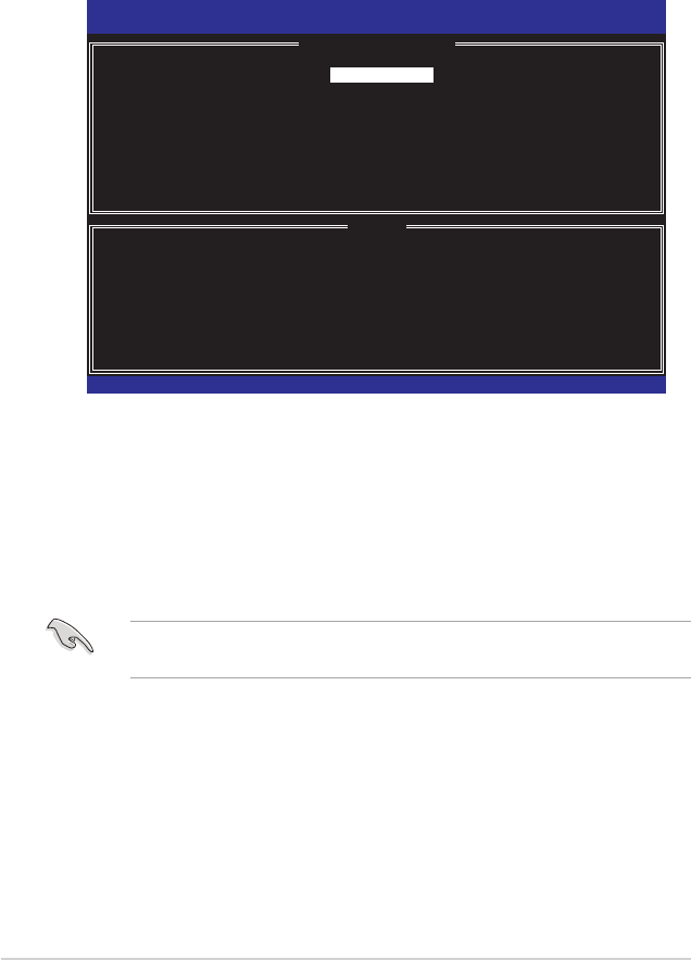
4-50 Chapter 4: Software support
Creating a RAID 10 set (RAID 0+1)
To create a RAID 10 set:
1. From the utility main menu, select 1. Create RAID Volume and press
<Enter>. The following screen appears.
2. Enter a name for the RAID 10 set and press <Enter>.
3. When the RAID Level item is highlighted, press the up/down arrow key to
select RAID 10 (RAID 0+1), and then press <Enter>.
4. When the Stripe Size item is highlighted, press the up/down arrow key to
select the stripe size for the RAID 10 array, and then press <Enter>. The
available stripe size values range from 4 KB to 64 KB. The default stripe size
is 64 KB.
We recommend a lower stripe size for server systems, and a higher stripe size
for multimedia computer systems used mainly for audio and video editing.
5. Enter the RAID volume capacity that you want and press <Enter>. The default
value indicates the maximum capacity allowed.
Intel(R) Matrix Storage Manager option ROM v8.0.0.1027 ICH10R wRAID5
Copyright(C) 2003-08 Intel Corporation. All Rights Reserved.
[ CREATE VOLUME MENU ]
[ HELP ]
Enter a unique volume name that has no special characters and is
16 characters or less.
[↑↓]-Change [TAB]-Next [ESC]-Previous Menu [Enter]-Select
Name:
RAID Level:
Disks:
Strip Size:
Capacity:
Volume10
RAID10(RAID0+1)
Select Disks
64KB
XXX GB
Create Volume

ASUS P6T Deluxe V2 4-51
Creating a RAID 5 set (parity)
To create a RAID 5 set:
1. From the utility main menu, select 1. Create RAID Volume and press
<Enter>. The following screen appears.
WARNING: ALL DATA ON SELECTED DISKS WILL BE LOST.
Are you sure you want to create this volume? (Y/N):
7. Press <Y> to create the RAID volume and return to the main menu or <N> to
go back to the Create Volume menu.
6. Press <Enter> when the Create Volume item is highlighted. The following
warning message appears.
2. Enter a name for the RAID 5 set and press <Enter>.
3. When the RAID Level item is highlighted, press the up/down arrow key to
select RAID 5(Parity), and then press <Enter>.
Intel(R) Matrix Storage Manager option ROM v8.0.0.1027 ICH10R wRAID5
Copyright(C) 2003-08 Intel Corporation. All Rights Reserved.
[ CREATE VOLUME MENU ]
[ HELP ]
Enter a unique volume name that has no special characters and is
16 characters or less.
[↑↓]-Change [TAB]-Next [ESC]-Previous Menu [Enter]-Select
Name:
RAID Level:
Disks:
Strip Size:
Capacity:
Volume5
RAID5(Parity)
Select Disks
64KB
XXX GB
Create Volume
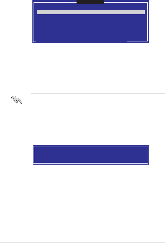
4-52 Chapter 4: Software support
4. The Disks item is highlighted, press <Enter> to select the hard disk drives to
congure as RAID. The following screen appears.
5. Use the up/down arrow key to highlight the drive you want to set, and then
press <Space> to select. A small triangle marks the selected drive. Press
<Enter> after completing your selection.
6. When the Stripe Size item is highlighted, press the up/down arrow key to
select the stripe size for the RAID 5 array, and then press <Enter>. The
available stripe size values range from 16 KB to 128 KB. The default stripe
size is 64 KB.
We recommend a lower stripe size for server systems, and a higher stripe size
for multimedia computer systems used mainly for audio and video editing.
7. Enter the RAID volume capacity that you want and then press <Enter>. The
default value indicates the maximum allowed capacity.
8. Press <Enter> when the Create Volume item is highlighted. The following
warning message appears.
WARNING: ALL DATA ON SELECTED DISKS WILL BE LOST.
Are you sure you want to create this volume? (Y/N):
9. Press <Y> to create the RAID volume and return to the main menu or <N> to
go back to the Create Volume menu.
[ SELECT DISKS ]
[↑↓]-Previous/Next [SPACE]-SelectsDisk [ENTER]-Done
Port Drive Model Serial # Size Status
0 XXXXXXXXXXXX XXXXXXXX XX.XGB Non-RAID Disk
1 XXXXXXXXXXXX XXXXXXXX XX.XGB Non-RAID Disk
2 XXXXXXXXXXXX XXXXXXXX XX.XGB Non-RAID Disk
3 XXXXXXXXXXXX XXXXXXXX XX.XGB Non-RAID Disk
Select 3 to 6 disks to use in creating the volume.

ASUS P6T Deluxe V2 4-53
4.5.2 Creating a RAID driver disk in Windows®
To create a RAID driver disk in Windows®:
1. Start Windows®.
2. Place the motherboard support DVD into the optical drive.
3. Go to the Make disk menu, and then click Intel ICH10R 32/64 bit RAID
Driver Disk to create an Intel® ICH10R RAID driver disk.
4. Insert a oppy disk into the oppy disk drive or connect a USB ash disk if
you are using Windows Vista OS.
5. Follow succeeding screen instructions to complete the process.
Write-protect the oppy disk to avoid computer virus infection.
4.5 Creating a RAID driver disk
A oppy disk with the RAID driver is required when installing Windows® XP/Vista
and later operating system on a hard disk drive that is included in a RAID set. For
Windows Vista user, you can create a RAID driver disk with a oppy disk drive or a
USB ash disk drive.
4.5.1 Creating a RAID driver disk without entering the OS
To create a RAID driver disk without entering the OS:
1. Boot your computer.
2. Press <Del> during POST to enter the BIOS setup utility.
3. Set the optical drive as the primary boot device.
4. Insert the support DVD into the optical drive.
5. Save changes and exit BIOS.
6. Press any key when the system prompts “Press any key to boot from the
optical drive.”
7. When the menu appears, press <1> to create a RAID driver disk.
8. Insert a formatted oppy disk into the oppy drive then press <Enter>.
9. Follow succeeding screen instructions to complete the process.

4-54 Chapter 4: Software support
To install the RAID driver in Windows XP:
1. During the OS installation, the system prompts you to press the <F6> key to
install third-party SCSI or RAID driver.
2. Press <F6> then insert the oppy disk with RAID driver into the oppy disk
drive.
3. When prompted to select the SCSI adapter to install, make sure you select
Intel(R) SATA RAID Controller (Desktop ICH10R).
4. Follow the succeeding screen instructions to complete the installation.
To install the RAID driver in Windows® Vista:
1. Insert the oppy disk/USB device with RAID driver into the oppy disk drive/USB
port.
2. During the OS installation, select Intel(R) SATA RAID Controller (Desktop
ICH10R).
3. Follow the succeeding screen instructions to complete the installation.
5
Multiple GPU
technology support
This chapter describes how to install and
congure multiple ATI® CrossFireX™ and
NVIDIA SLI™ graphics cards.

ASUS P6T Deluxe V2
Chapter summary 5
5.1 ATI® CrossFireX™ technology .................................................... 5-1
5.2 Installing CrossFireX™ graphics cards ..................................... 5-2
5.3 Software information ................................................................... 5-4
5.4 NVIDIA® SLI™ technology ........................................................... 5-6

ASUS P6T Deluxe V2 5-1
5.1 ATI® CrossFireX™ technology
The motherboard supports the ATI® CrossFireX™ technology that allows you to
install multi-graphics processing units (GPU) graphics cards. Follow the installation
procedures in this section.
5.1.1 Requirements
• In Dual CrossFireX mode, you should have two identical CrossFireX-ready
graphics cards or one CrossFireX-ready dual-GPU graphics card that are
ATI® certied.
• In Triple CrossFireX mode, you should have three identical CrossFireX-ready
graphics cards that are ATI® certied.
• Ensure that your graphics card driver supports the ATI CrossFireX
technology. Download the latest driver from the AMD website (www.amd.
com).
• Ensure that your power supply unit (PSU) can provide at least the minimum
power required by your system. See page 2-36 for details.
5.1.2 Before you begin
For ATI CrossFireX to work properly, you have to uninstall all existing graphics card
drivers before installing ATI CrossFireX graphics cards to your system.
To uninstall existing graphics card drivers
1. Close all current applications.
2. For Windows XP, go to Control Panel > Add/Remove Programs.
For Windows Vista, go to Control Panel > Programs and Features.
3. Select your current graphics card driver/s.
4. For Windows XP, select Add/Remove.
For Windows Vista, select Uninstall.
5. Turn off your computer.
• The ATI Triple CrossFireX technology is currently supported by Windows®
Vista operating system only.
• Visit the ATI Game website (http://game.amd.com) for the latest certied
graphics card and the supported 3D application list.
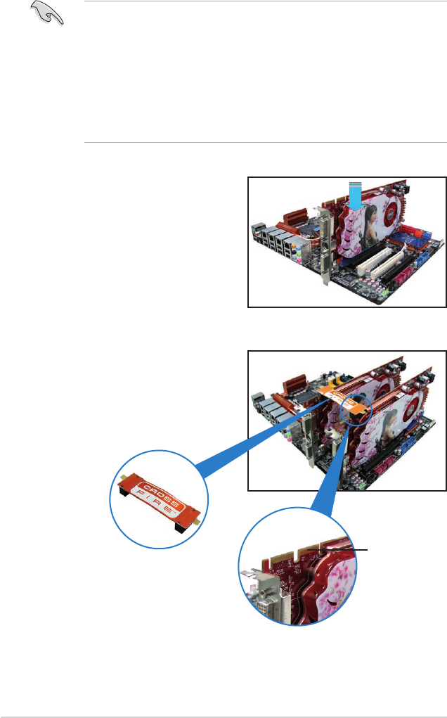
5-2 Chapter 5: Multiple GPU technology support
4. Align and rmly insert the
CrossFireX bridge connector to the
goldngers on each graphics card.
Ensure that the connector is rmly
in place.
5.2 Installing CrossFireX™ graphics cards
• Ensure that your power supply unit (PSU) can provide at least the minimum
power required by your system.
• We recommend that you install additional chassis fans for better thermal
environment.
• Install only the identical CrossFireX-ready graphics cards that are ATI®-
certied. Different types of graphics cards will not work together properly.
• The motherboard layout of this chapter is for reference purpose only and
may not exactly match with your motherboard.
5.2.1 Dual CrossFireX installation
1. Prepare two CrossFireX-ready
graphics cards.
2. Insert the two graphics card into the
PCIEX16 slots. If your motherboard
has more than two PCIEX16 slots,
refer to its user manual for the
locations of the PCIEX16 slots
recommended for multi-graphics
card installation.
3. Ensure that the cards are properly seated on the slots.
CrossFireX
goldngers
CrossFireX bridge
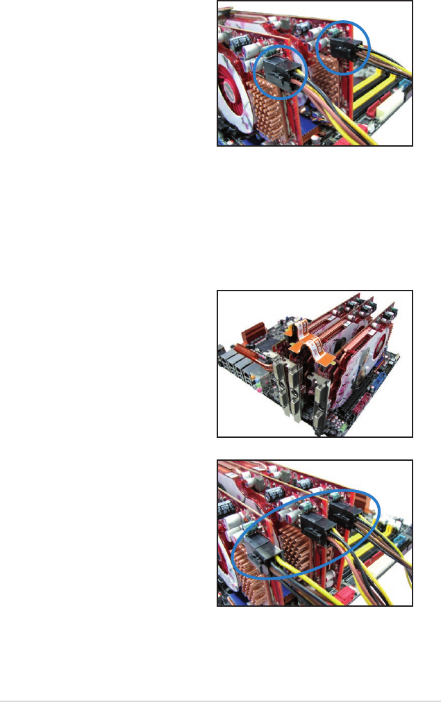
ASUS P6T Deluxe V2 5-3
5. Connect two independent auxiliary
power sources from the power
supply to the two graphics cards
separately.
6. Connect a VGA or a DVI cable to the
graphics card.
5.2.2 Triple CrossFireX installation
1. Prepare three CrossFireX-ready graphics cards.
2. Insert the three graphics card into the PCIEX16 slots. If your motherboard
has more than three PCIEX16 slots, refer to its user manual for the locations
of the PCIEX16 slots recommended for multi-graphics card installation.
3. Ensure that the cards are properly seated on the slots.
4. Align and rmly insert the two
CrossFireX bridge connectors to the
goldngers on each graphics card.
Ensure that the connectors are rmly
in place.
5. Connect three independent auxiliary
power sources from the power
supply to the three graphics cards
separately.
6. Connect a VGA or a DVI cable to the
graphics card.
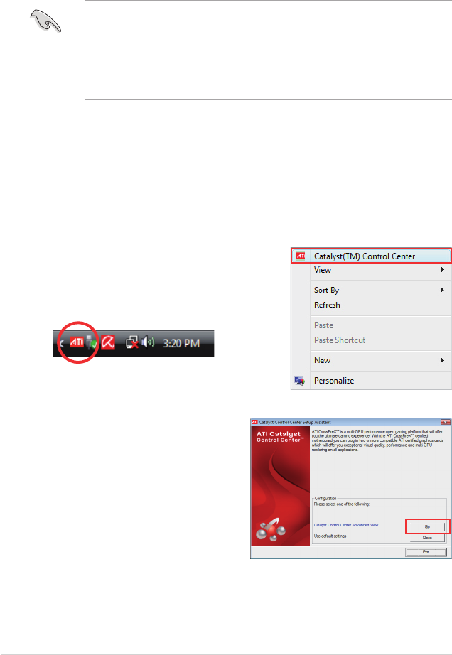
5-4 Chapter 5: Multiple GPU technology support
5.3 Software information
5.3.1 Installing the device drivers
Refer to the documentation that came with your graphics card package to install
the device drivers.
• Ensure that your PCI Express graphics card driver supports the ATI®
CrossFireX™ technology. Download the latest driver from the AMD website
(www.amd.com).
• If you are using a Triple or Quad CrossFireX system, ensure to install the
ATI Catalyst® driver under Windows® Vista™ OS. The ATI Triple or Quad
CrossFireX technology is currently supported by Windows® Vista™ only.
5.3.2 Enabling the ATI® CrossFireX™ technology
After installing your graphics cards and the device drivers, enable the
CrossFireX™ feature through the ATI Catalyst™ Control Center in Windows
environment.
Launching the ATI Catalyst Control Center
To launch the ATI Catalyst Control Center
1. Right-click on the Windows® desktop and
select Catalyst(TM) Control Center.
You can also right-click the ATI icon in
the Windows notication area and select
Cayalist Control Center.
2. The Catalyst Control Center Setup
Assistant appears when the system
detects the existance of multi-
graphics cards. Click Go to continue
to the Catalyst Control Center
Advanced View window.

ASUS P6T Deluxe V2 5-5
Enabling Dual CrossFireX technology
1. In the Catalyst Control Center
window, click Graphics Settings >
CrossFireX > Congure.
2. From the Graphics Adapter list,
select the graphics card to act as
the display GPU.
3. Select Enable CrossFireX.
4. Click Apply, and then click OK to
exit the window.
Enabling Triple CrossFireX technology
1. In the Catalyst Control Center
window, click Graphics Settings >
CrossFireX > Congure.
2. From the Graphics Adapter list,
select the graphics card to act as
the display GPU.
3. Select Enable CrossFireX.
4. From the list, select the appropriate
GPU combination to apply the
CrossFireX technology.
5. Click Apply, and then click OK to
exit the window.
1
2
3
4
1
2
3
5
4
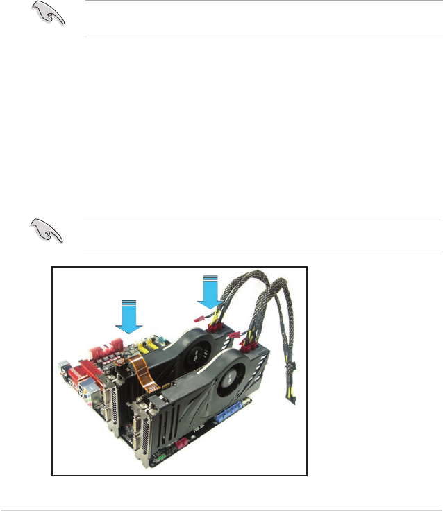
5-6 Chapter 5: Multiple GPU technology support
5.4 NVIDIA® SLI™ Technology
The motherboard supports the NVIDIA® SLI™ (Scalable Link Interface) technology
that allows you to install up to two identical PCI Express™ x16 graphics cards.
Follow the installation procedures in this section.
5.4.1 Requirements
• In SLI mode, you should have two identical SLI-ready graphics cards that are
NVIDIA® certied.
• Ensure that your graphics card driver supports the NVIDIA SLI technology.
Download the latest driver from the NVIDIA website (www.nvidia.com).
• Ensure that your power supply unit (PSU) can provide at least the minimum
power required by your system. See page 2-36 for details.
Visit the NVIDIA zone website (http://www.nzone.com) for the latest certied
graphics card and supported 3D application list.
5.4.2 Installing SLI™ graphics cards
1. Insert one graphics card into the PCIEX16_1 slot (blue) and the other into
the PCIEX16_2 slot (white). Ensure that the cards are properly seated on the
slots.
2. Align and insert the SLI connector to the goldngers on each graphics card.
Ensure that the connector is rmly in place.
3. Connect auxiliary power source from the power supply to the two graphics
cards separately.
4. Connect a VGA or a DVI-I cable to the graphics card/s.
We recommend that you install an additional chassis fan for better thermal
environment.
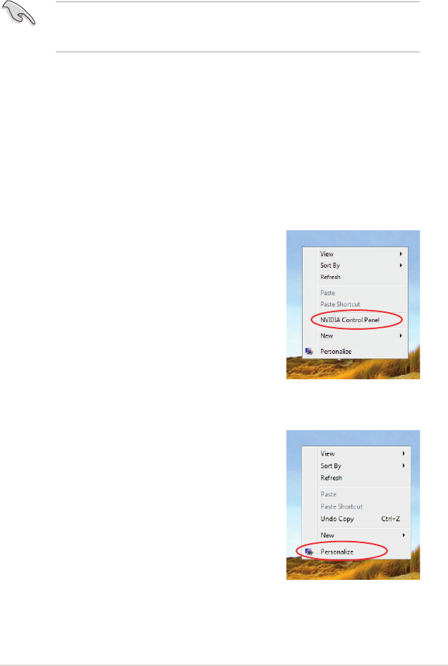
ASUS P6T Deluxe V2 5-7
5.4.3 Installing the device drivers
Refer to the documentation that came with your graphics card package to install
the device drivers.
5.4.4 Enabling the NVIDIA® SLI™ technology in Windows®
After installing your graphics cards and the device drivers, enable the SLI feature
in NVIDIA® Control Panel under the Windows® Vista™ operating system.
Launching the NVIDIA Control Panel
You can launch the NVIDIA Control Panel by the following two methods.
(A) Right click on the empty space of the Windows®
desktop and select NVIDIA Control Panel.
The NVIDIA Control Panel window appears (See
Step B5 on page 5-9).
(B1) If you cannot see the NVIDIA Control Panel item
in step (A), select Personalize.
Ensure that your PCI Express graphics card driver supports the NVIDIA® SLI™
technology. Download the latest driver from the NVIDIA website (www.nvidia.
com).
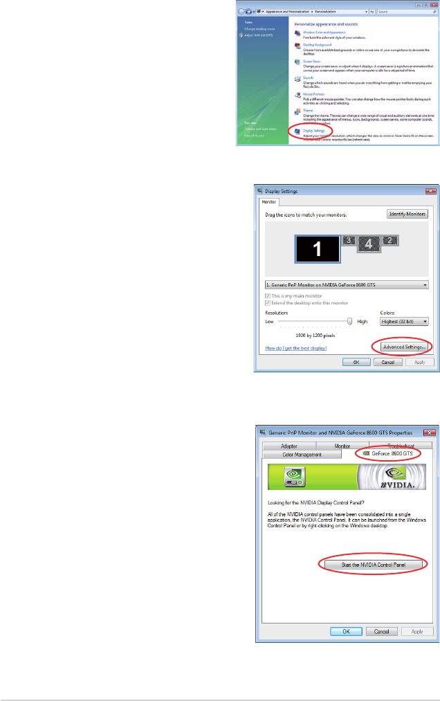
5-8 Chapter 5: Multiple GPU technology support
(B2) From the Personalization window,
select Display Settings.
(B3) From the Display Settings dialog box,
click Advanced Settings.
(B4) Select the NVIDIA GeForce tab, and
then click Start the NVIDIA Control
Panel.
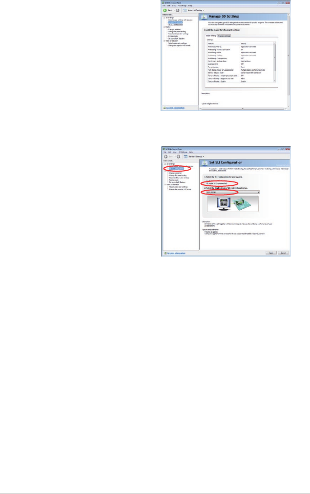
ASUS P6T Deluxe V2 5-9
(B5) The NVIDIA Control Panel window
appears.
Enabling SLI conguration
From the NVIDIA Control Panel window,
select Set SLI Conguration. Click
Enable SLI and set the display for viewing
SLI rendered content. When done, click
Apply.

5-10 Chapter 5: Multiple GPU technology support
