Asus Pike 2208 E7568 Users Manual
E7568_PIKE_2208 E7568_PIKE_2208
2015-03-09
: Asus Asus-Pike-2208-E7568-Users-Manual-580754 asus-pike-2208-e7568-users-manual-580754 asus pdf
Open the PDF directly: View PDF ![]() .
.
Page Count: 86
- Notices
- About this guide
- PIKE 2208 specifications summary
- Chapter 1: Product introduction
- Chapter 2: RAID configuration
- Chapter 3: Driver installation
LSISAS RAID card
PIKE 2208
User Guide

ii
E7568
First Edition (V1)
August 2012
Copyright © 2012 ASUSTeK COMPUTER INC. All Rights Reserved.
No part of this manual, including the products and software described in it, may be reproduced,
transmitted, transcribed, stored in a retrieval system, or translated into any language in any form or by any
means, except documentation kept by the purchaser for backup purposes, without the express written
permission of ASUSTeK COMPUTER INC. (“ASUS”).
Product warranty or service will not be extended if: (1) the product is repaired, modied or altered, unless
such repair, modication of alteration is authorized in writing by ASUS; or (2) the serial number of the
product is defaced or missing.
ASUS PROVIDES THIS MANUAL “AS IS” WITHOUT WARRANTY OF ANY KIND, EITHER EXPRESS
OR IMPLIED, INCLUDING BUT NOT LIMITED TO THE IMPLIED WARRANTIES OR CONDITIONS OF
MERCHANTABILITY OR FITNESS FOR A PARTICULAR PURPOSE. IN NO EVENT SHALL ASUS, ITS
DIRECTORS, OFFICERS, EMPLOYEES OR AGENTS BE LIABLE FOR ANY INDIRECT, SPECIAL,
INCIDENTAL, OR CONSEQUENTIAL DAMAGES (INCLUDING DAMAGES FOR LOSS OF PROFITS,
LOSS OF BUSINESS, LOSS OF USE OR DATA, INTERRUPTION OF BUSINESS AND THE LIKE),
EVEN IF ASUS HAS BEEN ADVISED OF THE POSSIBILITY OF SUCH DAMAGES ARISING FROM ANY
DEFECT OR ERROR IN THIS MANUAL OR PRODUCT.
SPECIFICATIONS AND INFORMATION CONTAINED IN THIS MANUAL ARE FURNISHED FOR
INFORMATIONAL USE ONLY, AND ARE SUBJECT TO CHANGE AT ANY TIME WITHOUT NOTICE,
AND SHOULD NOT BE CONSTRUED AS A COMMITMENT BY ASUS. ASUS ASSUMES NO
RESPONSIBILITY OR LIABILITY FOR ANY ERRORS OR INACCURACIES THAT MAY APPEAR IN THIS
MANUAL, INCLUDING THE PRODUCTS AND SOFTWARE DESCRIBED IN IT.
Products and corporate names appearing in this manual may or may not be registered trademarks or
copyrights of their respective companies, and are used only for identication or explanation and to the
owners’ benet, without intent to infringe.

iii
Contents
Notices .......................................................................................................... v
About this guide .......................................................................................... v
PIKE 2208 specications summary ......................................................... vii
Chapter 1: Product introduction
1.1 Welcome! ...................................................................................... 1-2
1.2 Package contents ......................................................................... 1-2
1.3 Card layout ................................................................................... 1-3
1.4 System requirements ................................................................... 1-4
1.5 Card installation ........................................................................... 1-5
Chapter 2: RAID conguration
2.1 Setting up RAID ............................................................................ 2-2
2.1.1 RAID denitions .............................................................. 2-2
2.1.2 Installing hard disk drives ................................................ 2-3
2.2 LSI WebBIOS Conguration Utility ............................................. 2-4
2.2.1 Starting the WebBIOS CU............................................... 2-5
2.2.2 WebBIOS CU main screen options ................................. 2-6
2.2.3 Creating a Storage Conguration ................................... 2-8
2.2.4 Viewing and Changing Device Properties ..................... 2-30
2.2.5 Viewing System Event Information ............................... 2-37
2.2.6 Managing Congurations .............................................. 2-38
2.3 MegaRAID Storage Manager ..................................................... 2-42
2.3.1 Hardware and Software Requirements ......................... 2-42
2.3.2 Installing MegaRAID Storage Manager Software on
Microsoft Windows OS .................................................. 2-42
2.3.3 Installing MegaRAID Storage Manager Software for
Linux ............................................................................. 2-46
2.3.4 Linux Error Messages ................................................... 2-47
2.3.5 Starting the MegaRAID Storage Manager Software ..... 2-48
2.3.6 MegaRAID Storage Manager Window .......................... 2-50
Chapter 3: Driver installation
3.1 RAID driver installation ............................................................... 3-2
3.2 Windows® Server 2003 OS Driver Installation ........................... 3-4
3.2.1 During Windows® Server 2003 OS installation ............... 3-4
3.2.2 After Windows® Server 2003 OS installation .................. 3-6

iv
3.3 Windows® Server 2008 OS Driver Installation ........................... 3-9
3.3.1 During Windows® Server 2008 OS installation ............... 3-9
3.3.2 After Windows® Server 2008 OS installation .................3-11
3.4 Red Hat® Enterprise Linux OS 5 Driver Installation ................ 3-13
3.5 SUSE® Linux OS 11 Driver Installation ..................................... 3-15
ASUS contact information .......................................................................... 1
Contents

v
About this guide
This user guide contains the information you need when installing and conguring
the server management board.
How this guide is organized
This guide contains the following parts:
• Chapter 1: Product introduction
This chapter offers the PIKE 2208 SAS RAID card features and the new
technologies it supports.
• Chapter 2: RAID conguration
This chapter provides instructions on setting up, creating, and conguring
RAID sets using the available utilities.
• Chapter 3: Driver installation
This chapter provides instructions for installing the RAID drivers on different
operating systems.
Where to nd more information
Refer to the following sources for additional information and for product and
software updates.
1. ASUS websites
The ASUS website provides updated information on ASUS hardware and
software products. Refer to the ASUS contact information.
2. Optional documentation
Your product package may include optional documentation, such as warranty
yers, that may have been added by your dealer. These documents are not
part of the standard package.
Notices
Australia statement notice
From 1 January 2012 updated warranties apply to all ASUS products, consistent
with the Australian Consumer Law. For the latest product warranty details, please
visit http://support.asus.com. Our goods come with guarantees that cannot be
excluded under the Australian Consumer Law. You are entitled to a replacement or
refund for a major failure and compensation for any other reasonably foreseeable
loss or damage. You are also entitled to have the goods repaired or replaced if the
goods fail to be of acceptable quality and the failure does not amount to a major
failure.
If you require assistance please call ASUS Customer Service 1300 2787 88 or visit
us at http://support.asus.com

vi
Typography
Bold text Indicates a menu or an item to select.
Italics
Used to emphasize a word or a phrase.
<Key> Keys enclosed in the less-than and greater-than sign means
that you must press the enclosed key.
Example: <Enter> means that you must press the Enter or
Return key.
<Key1+Key2+Key3> If you must press two or more keys simultaneously, the key
names are linked with a plus sign (+).
Example: <Ctrl+Alt+Del>
Command Means that you must type the command exactly as shown,
then supply the required item or value enclosed in brackets.
Example: At the DOS prompt, type the command line:
format a:
DANGER/WARNING: Information to prevent injury to yourself when
trying to complete a task.
CAUTION: Information to prevent damage to the components when
trying to complete a task.
NOTE: Tips and additional information to help you complete a task.
IMPORTANT: Instructions that you MUST follow to complete a task.
Conventions used in this guide
To make sure that you perform certain tasks properly, take note of the following
symbols used throughout this manual.

vii
PIKE 2208 specications summary
* The OS support depends on the motherboard’s OS support list.
** Specications are subject to change without notice.
Controller LSI 2208 6Gb/s SAS Controller
Interface ASUS PIKE interface
Ports 8 ports
Support Device SAS / SAS II devices
SATA / SATA II / SATA III devices
Data transfer rate SATA III and SAS II 6Gb/s per PHY
RAID level • RAID 0 / 1 / 10 / 5 / 50 / 6 / 60
• Max. physical Disk qty for RAID: 32
Cache 1GB onboard SDRAM
Backup Support Header reserved for LSI Cache Vault (acquired from LSI
existing distribution channel)
OS support* Windows® Server 2003 Enterprise Edition R2 SP2
Windows® Server 2008 Enterprise Edition R2 SP1
Windows® 7 (Ultimate) SP1
Red Hat Enterprise Linux AS 5.8
Red Hat Enterprise Linux AS 6.2
SuSE Linux Enterprise Server 10.4
SuSE Linux Enterprise Server 11.2
Cent OS 5.7
Cent OS 5.8
Cent OS 6.2
Free BSD 8.3
Free BSD 9.0
Fedora 17
Citrix Xen Server 6.0.2
Form factor 6.44 in x 3.02 in (2U compatible)

viii
1
Chapter 1: Product
introduction
This chapter offers the PIKE 2208 SAS RAID
card features and the new technologies it
supports.
1-2 Chapter 1: Product introduction
1.1 Welcome!
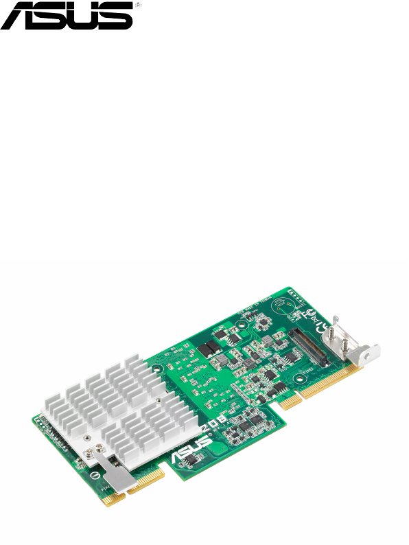
Thank you for buying an ASUS® PIKE 2208 SAS RAID card!
The ASUS PIKE 2208 allows you to create RAID 0, 1, 10, 5, 50, 6, and 60 sets
from SATA/SATA II/SATA III/SAS/SAS II hard disk drives connected to the SAS
connectors on the motherboard.
Before you start installing the RAID card, check the items in your package with the
list below.
1.2 Package contents
Check your package for the following items.
Standard Gift Box Pack Standard Bulk Pack
ASUS PIKE 2208 SAS RAID card 1 1
Support CD 1 1
User Guide 1 1
SATA cable* 8 —
Packing Quantity 1 pc per carton 3 pcs per carton
• The number of the SATA cable varies with product SKU.
• If any of the above items is damaged or missing, contact your retailer.
ASUS PIKE 2208 1-3
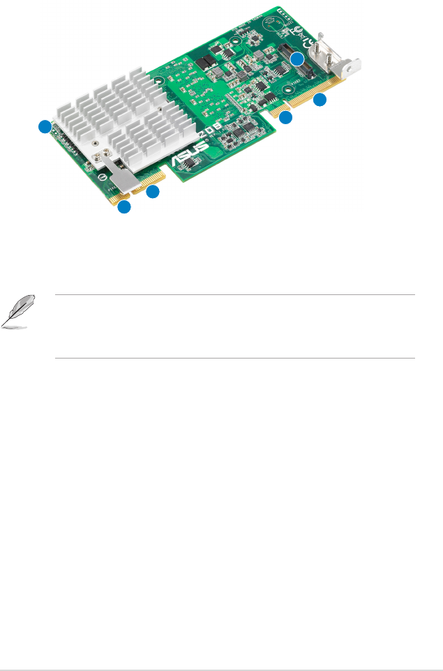
1.3 Card layout
The illustration below shows the major components of the RAID card.
Front
1. CacheVault connector
2. ASUS PIKE interface-1: PCI-E Gen3 x8
3. ASUS PIKE interface-2: 8-port SAS signal with SGPIO interface*
* The SGPIO interface is used for visibility into drive activity, failure and rebuild
status, so that users could build high-performance and reliable storage
systems. Refer to the motherboard manual for detailed information about using
the SGPIO connectors on the motherboard.
3
3
2
2
1
4
4. SAS RAID card status LED (lights up and blinks to indicate that the card is
working normally)
1-4 Chapter 1: Product introduction
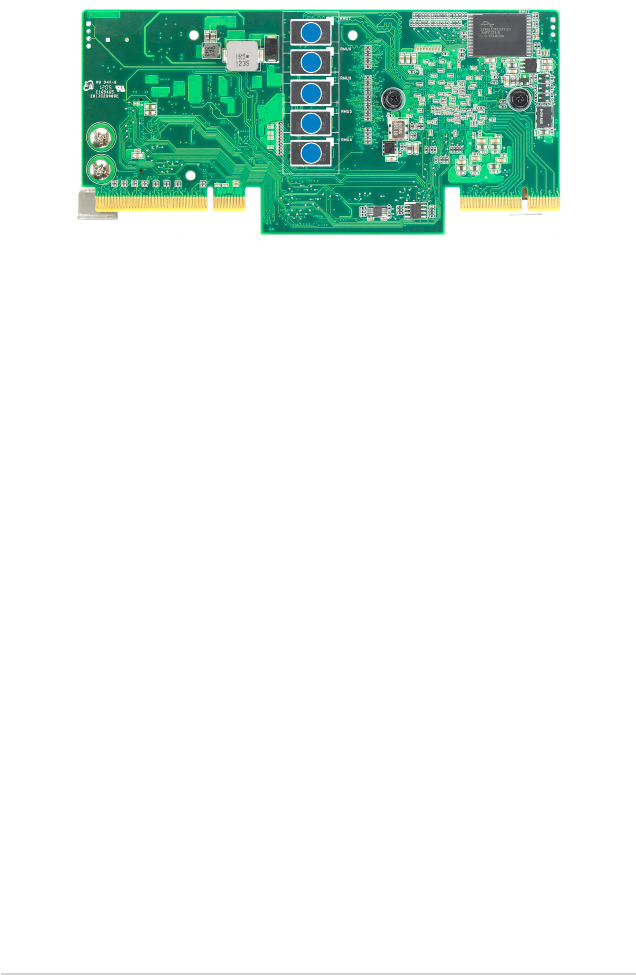
1
1. 1GB DDR3 SDRAM
Rear
1.4 System requirements
Before you install the PIKE 2208 SAS RAID card, check if the system meets the
following requirements:
• Workstation or server motherboard with a PIKE RAID card slot
• SAS or SATA hard disk drives
• Supporting operating system:
Windows® and Linux operating systems (refer to website for details)
• Other requirement:
- Appropriate thermal solution
- Certied power supply module
1
1
1
1
ASUS PIKE 2208 1-5
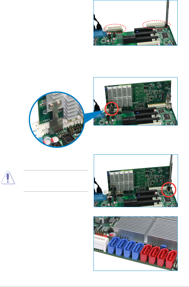
1. Locate the PIKE RAID card slot on
the motherboard then remove the
screws beside PIKE1 connector as
shown.
2. Align the golden ngers of the RAID card with the PIKE RAID card slot then
Insert the RAID card into the card slot. Ensure the card is completely inserted
into the card slot, and the heatsink latch is completely hooked to the edge of
the card slot.
1.5 Card installation
Follow below instructions to install the RAID card to your motherboard.
3. Secure the PIKE RAID card with
the screw that you removed earlier.
DO NOT overtighten the screw,
or the motherboard component
can be damaged.
4. Connect the hard disk drives
to the SAS connectors on the
motherboard.

1-6 Chapter 1: Product introduction
2
Chapter 2: RAID
conguration
This chapter provides instructions on setting
up, creating, and conguring RAID sets using
the available utilities.

2-2 Chapter 2: RAID conguration
2.1 Setting up RAID
The RAID card supports RAID 0, 1, 10, 5, 50, 6, and 60.
2.1.1 RAID denitions
RAID 0
(Data striping)
optimizes two identical hard disk drives to read and write
data in parallel, interleaved stacks. Two hard disks perform the same work as a
single drive but at a sustained data transfer rate, double that of a single disk alone,
thus improving data access and storage. Use of at least two new identical hard
disk drives is required for this setup.
RAID 1
(Data mirroring)
copies and maintains an identical image of data from one
drive to a second drive. If one drive fails, the disk array management software
directs all applications to the surviving drive as it contains a complete copy of
the data in the other drive. This RAID conguration provides data protection and
increases fault tolerance to the entire system. Use two new drives or use an
existing drive and a new drive for this setup. The new drive must be of the same
size or larger than the existing drive.
RAID 10 is a striped conguration with RAID 1 segments whose segments are
RAID 1 arrays. This conguration has the same fault tolerance as RAID 1, and
has the same overhead for fault-tolerance as mirroring alone. RAID 10 achieves
high input/output rates by striping RAID 1 segments. In some instances, a RAID
10 conguration can sustain multiple simultaneous drive failure. A minimum of four
hard disk drives is required for this setup.
RAID 5
stripes both data and parity information across three or more hard
disk drives. Among the advantages of RAID 5 conguration include better
HDD performance, fault tolerance, and higher storage capacity. The RAID
5 conguration is best suited for transaction processing, relational database
applications, enterprise resource planning, and other business systems. Use a
minimum of three identical hard disk drives for this setup.
RAID 50 is a combination of RAID 0 and RAID 5. It uses distributed parity and disk
striping and works best with data that requires high reliability, high request rates,
high data transfers, and medium-to-large capacity.
RAID 6 uses distributed parity, with two independent parity blocks per stripe, and
disk striping. A RAID 6 virtual drive can survive the loss of two drives without losing
data. A RAID 6 drive group, which requires a minimum of three drives, is similar to
a RAID 5 drive group. Blocks of data and parity information are written across all
drives. The parity information is used to recover the data if one or two drives fail in
the drive group.
RAID 60, a combination of RAID 0 and RAID 6, uses distributed parity, with two
independent parity blocks per stripe in each RAID set, and disk striping. A RAID 60
virtual drive can survive the loss of two drives in each of the RAID 6 sets without
losing data. It works best with data that requires high reliability, high request rates,
high data transfers, and medium-to-large capacity.

ASUS PIKE 2208 2-3
• Having RAID 0 and RAID 5 virtual disks in the same physical array is notHaving RAID 0 and RAID 5 virtual disks in the same physical array is not
recommended. If a drive in the physical array has to be rebuilt, the RAID 0
virtual disk will cause a failure during the rebuild.
• If you want to boot the system from a hard disk drive included in a created
RAID set, copy rst the RAID driver from the support CD to a oppy disk
before you install an operating system to the selected hard disk drive.
2.1.2 Installing hard disk drives
The RAID card supports SAS for RAID set conguration. For optimal performance,
install identical drives of the same model and capacity when creating a disk array.
To install SAS hard disks for RAID conguration:
1. Install the SAS hard disks into the drive bays following the instructions in the
system user guide.
2. Connect a SAS signal cable to the signal connector at the back of each drive
and to the SAS connector on the motherboard.
3. Connect a power cable to the power connector on each drive.

2-4 Chapter 2: RAID conguration
2.2 LSI WebBIOS Conguration Utility
The LSI WebBIOS Conguration Utility (CU) is an integrated RAID solution that
allows you to create RAID 0, 1, 10, 5, 50, 6, and 60 sets from SATA/SATA II/SATA
III/SAS/SAS II hard disk drives supported by the LSI 2208 6Gb/s SAS controller.
You can also use the WebBIOS CU to do the following tasks:
• Create drive groups and virtual drives for storage congurations
• Delete virtual drives
• Migrate a storage conguration to a different RAID level
• Detect conguration mismatches
• Import a foreign conguration
• Display controller, virtual drive, drive, and change parameters.
• Scan devices connected to the controller
• Initialize virtual drives
• Check congurations for data consistency
• Create a CacheCade™ conguration
• You may use disks of different sizes; however, the size of the smallest disk
determines the “logical” size of each member disk.
• DO NOT combine Serial ATA and SAS disk drives in one volume.
• The RAID setup screens shown in this section are for reference only and
may not exactly match the items on your screen due to the controller
version difference.

ASUS PIKE 2208 2-5
3. The Adapter Selection screen appears. If the system has multiple SAS
adapters, select an adapter.
4. Click Start to continue. The main WebBIOS CU screen appears.
2.2.1 Starting the WebBIOS CU
Follow these steps to start the WebBIOS CU and access the main screen.
1. Turn on the system after installing all SAS hard disk drives.
2. During POST, press <Ctrl+H> when the following screen appears
Press <Ctrl+Y> for Preboot CLI: this option is for advanced debug only!
LSI MegaRAID SAS-MFI BIOS
Version 5.33.00 (Build March 15, 2012)
Copyright(C) 2012 LSI Corporation
HA -0 (Bus 1 Dev 0) LSI MegaRAID SAS PCI Express ROMB
Battery Status: Not present
PCI SLOT ID LUN VENDOR PRODUCT REVISION CAPACITY
-------- -- --- ------ ------- -------- --------
0 LSI LSI MegaRAID SAS PCI Exp 3.190.15-1686 512MB
0 0 0 SEAGATE ST3300657SS 0000 286102MB
0 1 0 SEAGATE ST3300657SS 0000 286102MB
0 2 0 SEAGATE ST3300657SS 0000 286102MB
0 3 0 SEAGATE ST3300657SS 0000 286102MB
0 Virtual Drive(s) found on the host adapter.
0 Virtual Drive(s) handled by BIOS
Press <Ctrl><H> for WebBIOS or press <Ctrl><Y> for Preboot CLI
2-6 Chapter 2: RAID conguration
WebBIOS CU Toolbar Icons
Icon Description
Click this icon to return to the main screen from any other WebBIOS CU screen.
Click this icon to return to the previous screen that you were viewing.
Click this icon to exit the WebBIOS CU program.
Click this icon to turn off the sound on the onboard controller alarm.
Click this icon to display information about the WebBIOS CU version, bus
number, and device number.
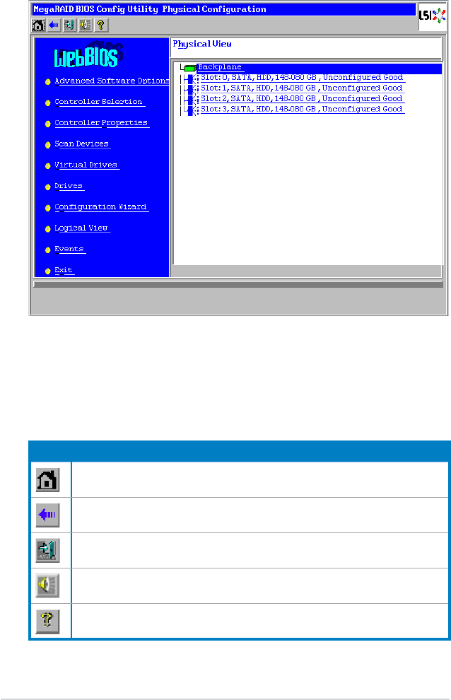
2.2.2 WebBIOS CU main screen options
This is the Physical View screen which displays the drives that are connected to
the controller. To toggle between the physical view and logical view of the storage
devices connected to the controller, click Physical View or Logical View in the
menu on the left. When the Logical View screen is displayed, you can see all the
virtual drives that are congured on this controller.

ASUS PIKE 2208 2-7
Here is a description of the options listed on the left of the main WebBIOS CU
screen:
• Advanced Software Option: Select this to allow you to enable the special
functionality or features that may not be available in the standard conguration
of the controller.
• Controller Selection: Select this to view the Adapter Selection screen, where
you can select a different SAS adapter. You can then view information about
the controller and the devices connected to it, or create a new conguration on
the controller.
• Controller Properties: Select this to view the properties of the currently
selected SAS controller.
• Scan Devices: Select this to have the WebBIOS CU re-scan the physical and
virtual drives for any changes in the drive status or the physical conguration.
The WebBIOS CU displays the results of the scan in the physical and virtual
drive descriptions.
• Virtual Drives: Select this to view the Virtual Drives screen, where you can
change and view virtual drive properties, initialize drives, and perform other
tasks.
• Drives: Select this to view the Drives screen, where you can view drive
properties, and perform other tasks.
• Conguration Wizard: Select this to start the Conguration Wizard and create
a new storage conguration, clear a conguration, or add a conguration.
• Logical View: Select this to toggle between the Physical View and Logical
View screens.
• Events: Select this to view system events in the Event Information screen.
• Exit: Select this to exit the WebBIOS CU and continue with system boot.
2-8 Chapter 2: RAID conguration
2.2.3 Creating a Storage Conguration
This section explains how to use the WebBIOS CU Conguration Wizard to
congure RAID arrays and virtual drives to create storage congurations.
The default settings of the conguration items mentioned in this section are
subject to change without notice, but the functions of the items will not be
affected.
Selecting the Conguration with the Conguration Wizard
Follow these steps to start the Conguration Wizard, and select a conguration
option and mode:
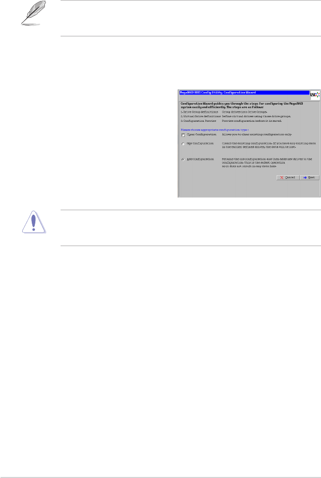
1. Click Conguration Wizard on
the WebBIOS main screen. The
rst Conguration Wizard screen
appears, as shown in the right
gure.
2. Select a conguration option.
If you choose the rst or second option, all existing data in the conguration
will be deleted. Make a backup of any data that you want to keep before you
choose an option.
• Clear Conguration: Clears the existing conguration.
• New Conguration: Clears the existing conguration and lets you
create a new conguration.
• Add Conguration: Retains the existing storage conguration and adds
new drives to it (this does not cause any data loss).
3. Click Next. A dialog box warns that you will lose data if you select Clear
Conguration or New Conguration.
4. On the next screen, select a conguration mode:
• Manual Conguration: Allows you to control all attributes of the new
storage conguration.
• Automatic Conguration: Automatically creates an optimal RAID
conguration.

ASUS PIKE 2208 2-9
If you select Automatic Conguration, you can choose the redundancy mode:
• Redundancy when possible: Automatically creates an optimal RAID
conguration, providing data redundancy.
• No Redundancy: Automatically creates a non-redundant RAID 0
conguration.
5. Click Next to continue.
Using Automatic Conguration
Follow these instructions to create a conguration with automatic conguration,
either with or without redundancy:
1. When WebBIOS displays the proposed new conguration, review the
information on the screen, and click Accept to accept it. (Or click Back to go
back and change the conguration.)
• RAID 0: If you selected Automatic Conguration and No
Redundancy, WebBIOS creates a RAID 0 conguration.
• RAID 1: If you selected Automatic Conguration and Redundancy
when possible, WebBIOS creates a RAID 1 conguration if only two
disk drives are available.
• RAID 6: If you selected Automatic Conguration and Redundancy
when possible, WebBIOS creates a RAID 6 conguration if three or
more disk drives are available.
2. Click Yes when you are prompted to save the conguration.
3. Click Yes when you are prompted to initialize the new virtual drive(s).
WebBIOS CU begins a background initialization of the virtual drives.
Using Manual Conguration: RAID 0
RAID 0 provides drive striping across all drives in the RAID drive group. RAID
0 does not provide any data redundancy but does offer excellent performance.
RAID 0 is ideal for applications that require high bandwidth but do not require fault
tolerance. RAID 0 also denotes an independent or single drive.
RAID level 0 is not fault-tolerant. If a drive in a RAID 0 drive group fails, the
whole virtual drive (all drives associated with the virtual drive) fails.
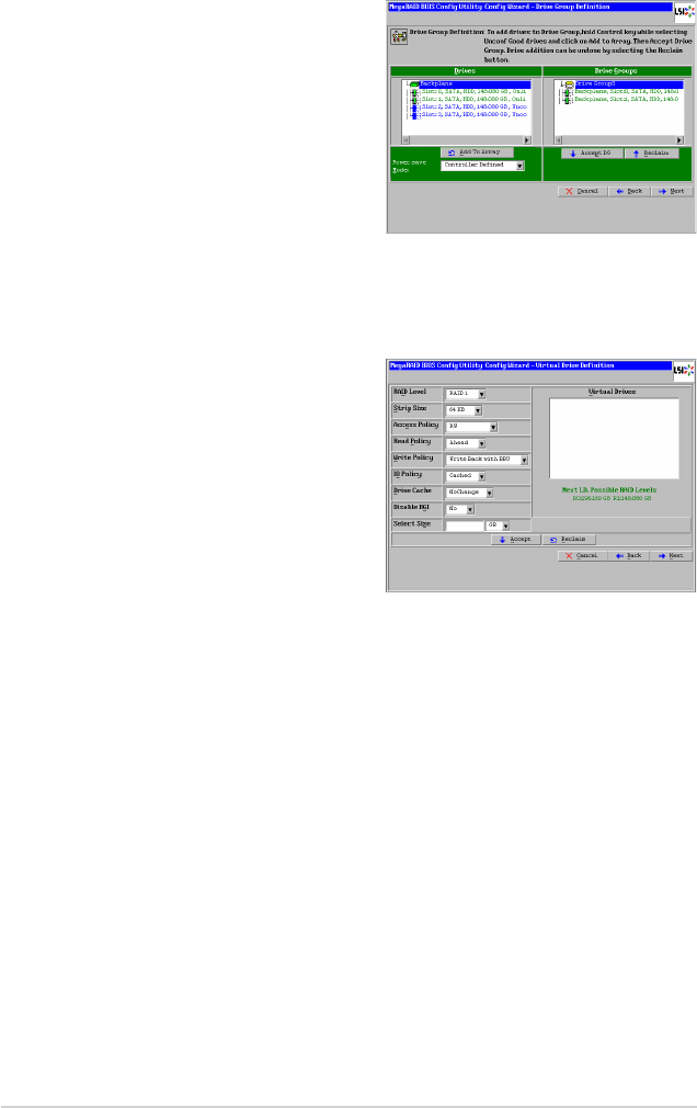
When you select Manual Conguration and click Next, the Drive Group Denition
screen appears. You use this screen to select drives to create drive groups.
1. Hold <Ctrl> while selecting two or more ready drives in the Drives panel on
the left until you have selected all desired drives for the drive group.
2-10 Chapter 2: RAID conguration
2. Click Add To Array to move the
drives to a proposed drive group
conguration in the Drive Groups
panel on the right, as shown in the
right gure.
3. Select a preferred power save
mode. The power save mode can
be Max, Max without cache, Auto,
None, and Controller dened. If
you need to undo the changes, click
the Reclaim button.
4. When you have nished selecting drives for the drive group, click Accept DG.
5. Click Next. The Span Denition screen appears. Select one of the available
drive groups, and then click Add to SPAN.
6. When nish, click Next. The Virtual
Drive Denition screen appears,
as shown in the right gure. Use
this screen to select the RAID level,
strip size, read policy, and other
attributes for the new virtual drives.
7. Change the virtual drive options
from the defaults listed on the
screen as needed.
Here are brief explanations of the
virtual drive options:
• RAID Level: The drop-down menu lists the possible RAID levels for the
virtual drive. Select RAID 0.
• Strip Size: The strip size species the size of the segment written to
each disk in a RAID conguration. You can set the strip size up to 1 MB.
A larger strip size produces higher read performance. If your computer
regularly performs random read requests, choose a smaller strip size.
The default is 256 KB.
• Access Policy: Select the type of data access that is allowed for this
virtual drive:
◊ RW: Allow read/write access. This is the default.
◊ Read Only: Allow read-only access.
◊ Blocked: Do not allow access.
• Read Policy: Specify the read policy for this virtual drive:
◊ No Read Ahead: This disables the read ahead capability.

ASUS PIKE 2208 2-11
◊ Always Read Ahead: This enables read ahead capability, which
allows the controller to read sequentially ahead of requested data and
to store the additional data in cache memory, anticipating that the data
will be needed soon. This speeds up reads for sequential data, but
there is little improvement when accessing random data. This is the
default.
• Write Policy: Specify the write policy for this virtual drive:
◊ Write Through: In Write Through mode, the controller sends a data
transfer completion signal to the host when the drive subsystem has
received all of the data in a transaction.
◊ Always Write Back: In Writeback mode, the controller sends a data
transfer completion signal to the host when the controller cache has
received all of the data in a transaction. This setting is recommended
in Standard mode.
• IO Policy: The IO Policy applies to reads on a specic virtual drive. It
does not affect the read ahead cache.
◊ Direct: In direct I/O mode, reads are not buffered in cache memory.
Data is transferred to the cache and the host concurrently. If the same
data block is read again, it comes from cache memory. This is the
default.
◊ Cached: In cached I/O mode, all reads are buffered in cache memory.
• Drive Cache: Specify the drive cache policy:
◊ Unchanged: Leave the current drive cache policy unchanged. This is
the default.
◊ Enable: Enable the drive cache.
◊ Disable: Disable the drive cache.
• Disable BGI: Specify the background initialization status:
◊ No: Leave background initialization enabled. This means that a new
conguration can be initialized in the background while you use
WebBIOS to do other conguration tasks. This is the default.
◊ Yes: Select Yes if you do not want to allow background initializations
for congurations on this controller.
• Select Size: Specify the size of the virtual drive in terabytes, gigabytes,
megabytes, or kilobytes. Normally, this would be the full size for RAID 0
shown in the Conguration panel on the right. You may specify a smaller
size if you want to create other virtual drives on the same drive group.
8. Click Accept to accept the changes to the virtual drive denition, or click
Reclaim to return to the previous settings.
2-12 Chapter 2: RAID conguration
9. Click Yes to conrm the write policy
mode you have chosen.
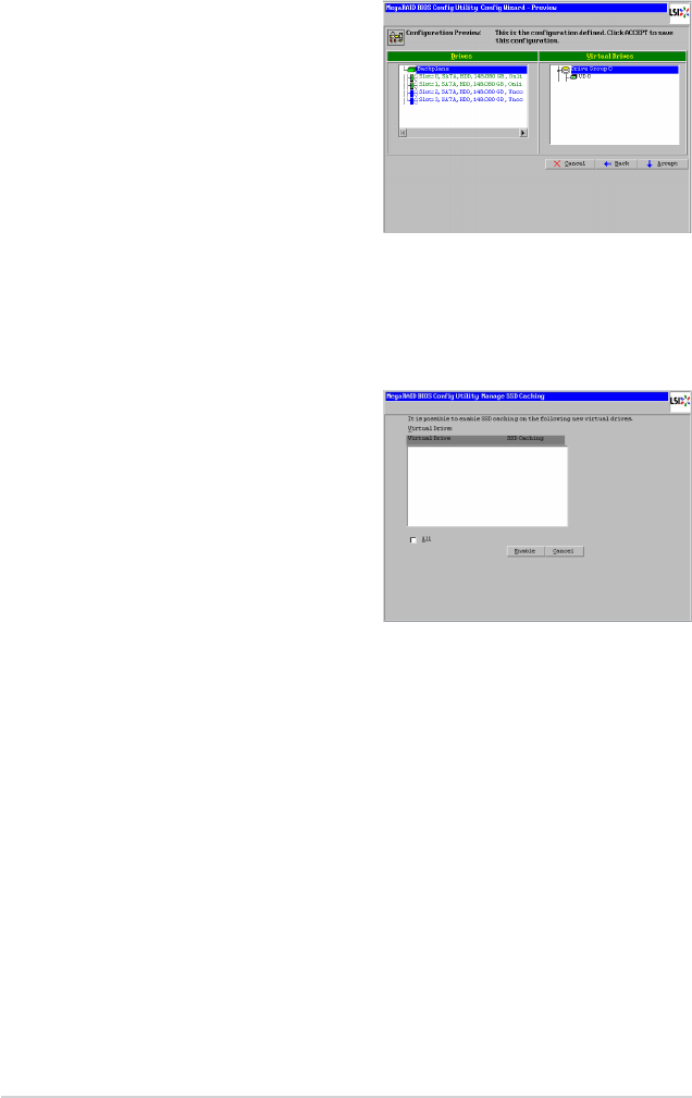
10. Click Next after you nish dening
virtual drives. The conguration
preview screen appears, as shown
in the right gure.
11. Check the information in the
conguration preview screen.
12. If the virtual drive conguration is
acceptable, click Accept to save
the conguration. Otherwise, click
Back to return to the previous screens and change the conguration.
13. If you accept the conguration, click Yes at the prompt to save the
conguration.
14. Click Yes at the prompt to start initialization.
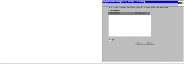
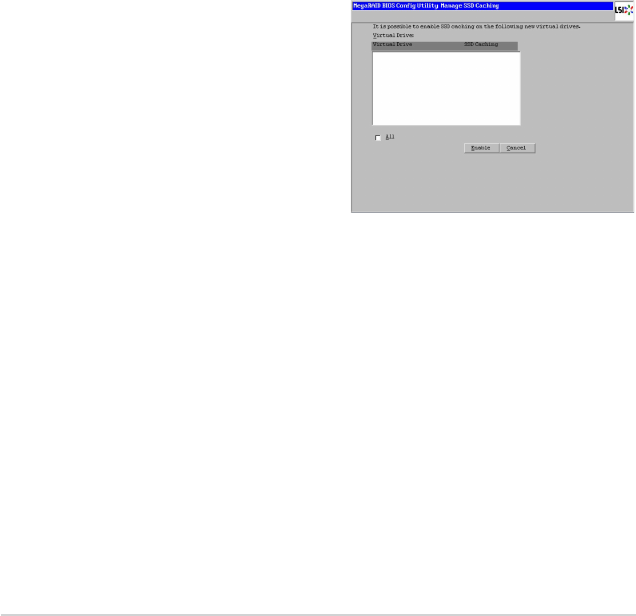
15. After the virtual drive is successfully
created, the Manage SSD Caching
screen appears. Click Cancel to
close the sceen.
Using Manual Conguration: RAID 1
In RAID 1, the RAID controller duplicates all data from one drive to a second
drive. RAID 1 provides complete data redundancy, but at the cost of doubling the
required data storage capacity. It is appropriate for small databases or any other
environment that requires fault tolerance but small capacity.
When you select Manual Conguration and click Next, the Drive Group
Denition screen appears. Use this screen to select drives to create drive groups.
1. Hold <Ctrl> while selecting two ready drives in the Drives panel on the left.
2. Click Add to Array to move the drives to a proposed drive group
conguration in the Drive Groups panel on the right.
3. Select a preferred power save mode. The power save mode can be Max,
Max without cache, Auto, None, and Controller dened. If you need to
undo the changes, click the Reclaim button.

ASUS PIKE 2208 2-13
4. When you have nished selecting drives for the drive group, click Accept DG.
5. Click Next. The Span Denition screen appears. Select one of the available
drive groups, and then click Add to SPAN.
6. When nish, click Next. The Virtual Drive Denition screen appears.
Use this screen to select the RAID level, strip size, read policy, and other
attributes for the new virtual drives.
7. Change the virtual drive options from the defaults listed on the screen as
needed.
Here are brief explanations of the virtual drive options:
• RAID Level: The drop-down menu lists the possible RAID levels for the
virtual drive. Select RAID 1.
• Strip Size: The strip size species the size of the segment written to
each disk in a RAID conguration. You can set the strip size up to 1 MB.
A larger strip size produces higher read performance. If your computer
regularly performs random read requests, choose a smaller strip size.
The default is 256 KB.
• Access Policy: Select the type of data access that is allowed for this
virtual drive:
◊ RW: Allow read/write access. This is the default.
◊ Read Only: Allow read-only access.
◊ Blocked: Do not allow access.
• Read Policy: Specify the read policy for this virtual drive:
◊ No Read Ahead: This disables the read ahead capability.
◊ Always Read Ahead: This enables read ahead capability, which
allows the controller to read sequentially ahead of requested data and
to store the additional data in cache memory, anticipating that the data
will be needed soon. This speeds up reads for sequential data, but
there is little improvement when accessing random data. This is the
default.
• Write Policy: Specify the write policy for this virtual drive:
◊ Write Through: In Write Through mode, the controller sends a data
transfer completion signal to the host when the drive subsystem has
received all of the data in a transaction.
◊ Always Write Back: In Writeback mode, the controller sends a data
transfer completion signal to the host when the controller cache has
received all of the data in a transaction. This setting is recommended
in Standard mode.
• IO Policy: The IO Policy applies to reads on a specic virtual drive. It
does not affect the read ahead cache.
2-14 Chapter 2: RAID conguration
◊ Direct: In direct I/O mode, reads are not buffered in cache memory.
Data is transferred to the cache and the host concurrently. If the same
data block is read again, it comes from cache memory. This is the
default.
◊ Cached: In cached I/O mode, all reads are buffered in cache memory.
• Drive Cache: Specify the drive cache policy:
◊ Unchanged: Leave the current drive cache policy unchanged. This is
the default.
◊ Enable: Enable the drive cache.
◊ Disable: Disable the drive cache.
• Disable BGI: Specify the background initialization status:
◊ No: Leave background initialization enabled. This means that a new
conguration can be initialized in the background while you use
WebBIOS to do other conguration tasks. This is the default.
◊ Yes: Select Yes if you do not want to allow background initializations
for congurations on this controller.
• Select Size: Specify the size of the virtual drive in terabytes, gigabytes,
megabytes, or kilobytes. Normally, this would be the full size for RAID 1
shown in the Conguration panel on the right. You may specify a smaller
size if you want to create other virtual drives on the same drive group.
8. Click Accept to accept the changes to the virtual drive denition, or click
Reclaim to return to the previous settings.
9. Click Yes to conrm the write policy mode you have chosen.
10. Click Next after you nish dening virtual disks. The conguration preview
screen appears.
11. Check the information in the conguration preview screen.
12. If the virtual drive conguration is acceptable, click Accept to save the
conguration. Otherwise, click Back to return to the previous screens and
change the conguration.
13. If you accept the conguration, click Yes at the prompt to save the
conguration.
14. Click Yes at the prompt to start initialization.
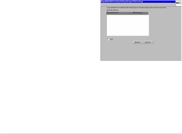
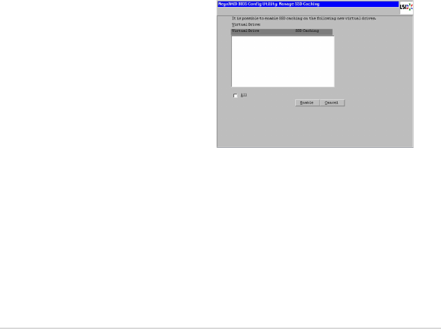
15. After the virtual drive is successfully
created, the Manage SSD Caching
screen appears. Click Cancel to
close the sceen.

ASUS PIKE 2208 2-15
Using Manual Conguration: RAID 10
RAID 10, a combination of RAID 1 and RAID 0, has mirrored drives. It breaks
up data into smaller blocks, then stripes the blocks of data to each RAID 1 drive
group. Each RAID 1 drive group then duplicates its data to its other drive. The size
of each block is determined by the strip size parameter. RAID 10 can sustain one
drive failure in each array while maintaining data integrity.
RAID 10 provides both high data transfer rates and complete data redundancy.
It works best for data storage that must have 100 percent redundancy of RAID
1 (mirrored drive groups) and that also needs the enhanced I/O performance of
RAID 0 (striped drive groups); it works well for medium-sized databases or any
environment that requires a higher degree of fault tolerance and moderate to
medium capacity.
When you select Manual Conguration and click Next, the Drive Group
Denition screen appears.
You can use the Drive Group Denition screen to select drives to create drive
groups.
1. Hold <Ctrl> while selecting two ready drives in the Drives panel on the left.
2. Click Add to Array to move the drives to a proposed two-drive drive group
conguration in the Drive Groups panel on the right.
3. Select a preferred power save mode. The power save mode can be Max,
Max without cache, Auto, None, and Controller dened. If you need to
undo the changes, click the Reclaim button.
4. Click Accept DG to create a RAID 1 drive group.
An icon for the next drive group displays in the right panel.
5. Click on the icon for the next drive group to select it.
6. Hold <Ctrl> while selecting two more ready drives in the Drives panel to
create a second RAID 1 drive group with two drives.
7. Click Add To Array to move the drives to a second two-drive drive group
conguration in the Drive Groups panel.
If you need to undo the changes, click the Reclaim button.
8. Repeat the previous three steps until you have selected all the drives you
want for the drive groups.
9. After you nish selecting drives for the drive groups, select each drive group
and click Accept DG for each.
10. Click Next. The Span Denition screen appears. This screen displays the
drive group holes you can select to add to a span.
11. Select one of the available drive groups with two drives from the Array With
Free Space drop-down list, and then click Add to SPAN.

2-16 Chapter 2: RAID conguration
12. Select a second drive group from the Array With Free Space drop-down list,
and click Add to SPAN.
Both drive groups display in the right frame under Span.
13. If there are additional drive groups with two drives each, you can add them to
the virtual drive.
14. When nish, click Next. The Virtual Drive Denition screen appears.
You can use this screen to select the RAID level, strip size, read policy, and
other attributes for the new virtual drives.
The WebBIOS Conguration Utility displays the maximum available capacity
while creating the RAID 10 drive group. In version 1.03 of the utility, the
maximum size of the RAID 10 drive group is the sum total of the two RAID 1
drive groups. In version 1.1, the maximum size is the size of the smaller drive
group multiplied by two.
15. Change the virtual drive options from the defaults listed on the screen as
needed.
Here are brief explanations of the virtual drive options:
• RAID Level: The drop-down menu lists the possible RAID levels for the
virtual drive. Select RAID 10.
• Strip Size: The strip size species the size of the segment written to
each disk in a RAID conguration. You can set the strip size up to 1 MB.
A larger strip size produces higher read performance. If your computer
regularly performs random read requests, choose a smaller strip size.
The default is 256 KB.
• Access Policy: Select the type of data access that is allowed for this
virtual drive:
◊ RW: Allow read/write access. This is the default.
◊ Read Only: Allow read-only access.
◊ Blocked: Do not allow access.
• Read Policy: Specify the read policy for this virtual drive:
◊ No Read Ahead: This disables the read ahead capability.
◊ Always Read Ahead: This enables read ahead capability, which
allows the controller to read sequentially ahead of requested data and
to store the additional data in cache memory, anticipating that the data
will be needed soon. This speeds up reads for sequential data, but
there is little improvement when accessing random data. This is the
default.
• Write Policy: Specify the write policy for this virtual drive:
◊ Write Through: In Write Through mode, the controller sends a data
transfer completion signal to the host when the drive subsystem has
received all of the data in a transaction.

ASUS PIKE 2208 2-17
◊ Always Write Back: In Writeback mode, the controller sends a data
transfer completion signal to the host when the controller cache has
received all of the data in a transaction. This setting is recommended
in Standard mode.
• IO Policy: The IO Policy applies to reads on a specic virtual drive. It
does not affect the read ahead cache.
◊ Direct: In direct I/O mode, reads are not buffered in cache memory.
Data is transferred to the cache and the host concurrently. If the same
data block is read again, it comes from cache memory. This is the
default.
◊ Cached: In cached I/O mode, all reads are buffered in cache memory.
• Drive Cache: Specify the drive cache policy:
◊ Unchanged: Leave the current drive cache policy unchanged. This is
the default.
◊ Enable: Enable the drive cache.
◊ Disable: Disable the drive cache.
• Disable BGI: Specify the background initialization status:
◊ No: Leave background initialization enabled. This means that a new
conguration can be initialized in the background while you use
WebBIOS to do other conguration tasks. This is the default.
◊ Yes: Select Yes if you do not want to allow background initializations
for congurations on this controller.
• Select Size: Specify the size of the virtual drive in terabytes, gigabytes,
megabytes, or kilobytes. Normally, this would be the full size for RAID 10
shown in the Conguration panel on the right. You may specify a smaller
size if you want to create other virtual drives on the same drive group.
16. Click Accept to accept the changes to the virtual drive denition, or click
Reclaim to to undo the changes.
17. Click Yes to conrm the write policy mode you have chosen.
18. When you nish dening virtual drives, click Next. The conguration preview
screen appears.
19. Check the information in the conguration preview screen.
20. If the virtual drive conguration is acceptable, click Accept to save the
conguration. Otherwise, click Cancel to end the operation and return to the
WebBIOS main menu, or click Back to return to the previous screens and
change the conguration.
21. If you accept the conguration, click Yes at the prompt to save the
conguration.
22. Click Yes at the prompt to start initialization.

2-18 Chapter 2: RAID conguration
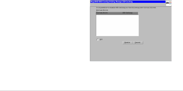
23. After the virtual drive is successfully
created, the Manage SSD Caching
screen appears. Click Cancel to
close the sceen.
Using Manual Conguration: RAID 5
RAID 5 uses drive striping at the block level and parity. In RAID 5, the parity
information is written to all drives. It is best suited for networks that perform a
lot of small input/output (I/O) transactions simultaneously. RAID 5 provides data
redundancy, high read rates, and good performance in most environments. It also
provides redundancy with lowest loss of capacity.
RAID 5 provides high data throughput. RAID 5 is useful for transaction processing
applications because each drive can read and write independently. If a drive fails,
the RAID controller uses the parity drive to recreate all missing information. You
can use RAID 5 for ofce automation and online customer service that require
fault tolerance. In addition, RAID 5 is good for any application that has high read
request rates but low write request rates.
When you select Manual Conguration and click Next, the Drive Group
Denition screen appears. You use this screen to select drives to create drive
groups.
1. Hold <Ctrl> while you select at least three ready drives in the Drives panel
on the left.
2. Click Add To Arrary to move the drives to a proposed drive group
conguration in the Drive Groups panel on the right.
3. Select a preferred power save mode. The power save mode can be Max,
Max without cache, Auto, None, and Controller dened. If you need to
undo the changes, click Reclaim.
4. After you nish selecting drives for the drive group, click Accept DG.
5. Click Next. The Span Denition screen appears. Select one of the available
drive groups, and then click Add to SPAN.
6. When nish, click Next. The Virtual Drive Denition screen appears. You
use this screen to select the RAID level, strip size, read policy, and other
attributes for the new virtual drives.
7. Change the virtual drive options from the defaults listed on the screen as
needed.

ASUS PIKE 2208 2-19
Here are brief explanations of the virtual disk options:
• RAID Level: The drop-down menu lists the possible RAID levels for the
virtual drive. Select RAID 5.
• Strip Size: The strip size species the size of the segment written to
each disk in a RAID conguration. You can set the strip size up to 1 MB.
A larger strip size produces higher read performance. If your computer
regularly performs random read requests, choose a smaller strip size.
The default is 256 KB.
• Access Policy: Select the type of data access that is allowed for this
virtual drive:
◊ RW: Allow read/write access. This is the default.
◊ Read Only: Allow read-only access.
◊ Blocked: Do not allow access.
• Read Policy: Specify the read policy for this virtual drive:
◊ No Read Ahead: This disables the read ahead capability.
◊ Always Read Ahead: This enables read ahead capability, which
allows the controller to read sequentially ahead of requested data and
to store the additional data in cache memory, anticipating that the data
will be needed soon. This speeds up reads for sequential data, but
there is little improvement when accessing random data. This is the
default.
• Write Policy: Specify the write policy for this virtual drive:
◊ Write Through: In Write Through mode, the controller sends a data
transfer completion signal to the host when the drive subsystem has
received all of the data in a transaction.
◊ Always Write Back: In Writeback mode, the controller sends a data
transfer completion signal to the host when the controller cache has
received all of the data in a transaction. This setting is recommended
in Standard mode.
• IO Policy: The IO Policy applies to reads on a specic virtual drive. It
does not affect the read ahead cache.
◊ Direct: In direct I/O mode, reads are not buffered in cache memory.
Data is transferred to the cache and the host concurrently. If the same
data block is read again, it comes from cache memory. This is the
default.
◊ Cached: In cached I/O mode, all reads are buffered in cache memory.
• Drive Cache: Specify the drive cache policy:
◊ Unchanged: Leave the current drive cache policy unchanged. This is
the default.
◊ Enable: Enable the drive cache.
◊ Disable: Disable the drive cache.
2-20 Chapter 2: RAID conguration
• Disable BGI: Specify the background initialization status:
◊ No: Leave background initialization enabled. This means that a new
conguration can be initialized in the background while you use
WebBIOS to do other conguration tasks. This is the default.
◊ Yes: Select Yes if you do not want to allow background initializations
for congurations on this controller.
• Select Size: Specify the size of the virtual drive in terabytes, gigabytes,
megabytes, or kilobytes. Normally, this would be the full size for RAID 5
shown in the Conguration panel on the right. You may specify a smaller
size if you want to create other virtual drives on the same drive group.
8. Click Accept to accept the changes to the virtual drive denition, or click
Reclaim to return to the previous settings.
9. Click Yes to conrm the write policy mode you have chosen.
10. Click Next after you nish dening virtual drives. The conguration preview
screen appears.
11. Check the information in the conguration preview screen.
12. If the virtual drive conguration is acceptable, click Accept to save the
conguration. Otherwise, click Back to return to the previous screens and
change the conguration.
13. If you accept the conguration, click Yes at the prompt to save the
conguration.
14. Click Yes at the prompt to start initialization.
15. After the virtual drive is successfully
created, the Manage SSD Caching
screen appears. Click Cancel to
close the sceen.

ASUS PIKE 2208 2-21
Using Manual Conguration: RAID 50
RAID 50 provides the features of both RAID 0 and RAID 5. RAID 50 uses both
distributed parity and drive striping across multiple drive groups. It provides
high data throughput, data redundancy, and very good performance. It is best
implemented on two RAID 5 drive groups with data striped across both drive
groups. Though multiple drive failures can be tolerated, only one drive failure can
be tolerated in each RAID 5 level drive group.
RAID 50 is appropriate when used with data that requires high reliability, high
request rates, high data transfer, and medium to large capacity.
When you select Manual Conguration and click Next, the Drive Group
Denition screen appears. You use this screen to select drives to create drive
groups.
1. Hold <Ctrl> while selecting at least three ready drives in the Drives panel on
the left.
2. Click Add To Array to move the drives to a proposed drive group
conguration in the Drive Groups panel on the right.
3. Select a preferred power save mode. The power save mode can be Max,
Max without cache, Auto, None, and Controller dened. If you need to
undo the changes, click Reclaim.
4. Click Accept DG to create a RAID 5 drive group.
An icon for a second drive group displays in the right panel.
5. Click on the icon for the second drive group to select it.
6. Hold <Ctrl> while selecting at least three more ready drives in the Drives
panel to create a second drive group.
7. Click Add To Array to move the drives to a proposed drive group
conguration in the Drive Groups panel on the right.
If you need to undo the changes, click Reclaim.
8. After you nish selecting drives for the drive groups, select each drive group
and click Accept DG for each.
9. Click Next. The Span Denition screen appears. This screen displays the
drive group holes you can select to add to a span.
10. Select one of the available drive groups from the Array With Free Space
drop-down list, and then click Add to SPAN.
11. Select a second drive group from the Array With Free Space drop-down list,
and click Add to SPAN.
Both drive groups display in the right frame under Span.
12. When nish, click Next. The Virtual Drive Denition screen appears. You
use this screen to select the RAID level, strip size, read policy, and other
attributes for the new virtual drive(s).

2-22 Chapter 2: RAID conguration
13. If there are additional drive groups with three or more drives each, you can
add them to the virtual drive.
14. Change the virtual drive options from the defaults listed on the screen as
needed.
Here are brief explanations of the virtual drive options:
• RAID Level: The drop-down menu lists the possible RAID levels for the
virtual drive. Select RAID 50.
• Strip Size: The strip size species the size of the segment written to
each disk in a RAID conguration. You can set the strip size up to 1 MB.
A larger strip size produces higher read performance. If your computer
regularly performs random read requests, choose a smaller strip size.
The default is 256 KB.
• Access Policy: Select the type of data access that is allowed for this
virtual drive:
◊ RW: Allow read/write access. This is the default.
◊ Read Only: Allow read-only access.
◊ Blocked: Do not allow access.
• Read Policy: Specify the read policy for this virtual drive:
◊ No Read Ahead: This disables the read ahead capability.
◊ Always Read Ahead: This enables read ahead capability, which
allows the controller to read sequentially ahead of requested data and
to store the additional data in cache memory, anticipating that the data
will be needed soon. This speeds up reads for sequential data, but
there is little improvement when accessing random data. This is the
default.
• Write Policy: Specify the write policy for this virtual drive:
◊ Write Through: In Write Through mode, the controller sends a data
transfer completion signal to the host when the drive subsystem has
received all of the data in a transaction.
◊ Always Write Back: In Writeback mode, the controller sends a data
transfer completion signal to the host when the controller cache has
received all of the data in a transaction. This setting is recommended
in Standard mode.
• IO Policy: The IO Policy applies to reads on a specic virtual drive. It
does not affect the read ahead cache.
◊ Direct: In direct I/O mode, reads are not buffered in cache memory.
Data is transferred to the cache and the host concurrently. If the same
data block is read again, it comes from cache memory. This is the
default.
◊ Cached: In cached I/O mode, all reads are buffered in cache memory.
ASUS PIKE 2208 2-23
• Drive Cache: Specify the drive cache policy:
◊ Unchanged: Leave the current drive cache policy unchanged. This is
the default.
◊ Enable: Enable the drive cache.
◊ Disable: Disable the drive cache.
• Disable BGI: Specify the background initialization status:
◊ No: Leave background initialization enabled. This means that a new
conguration can be initialized in the background while you use
WebBIOS to do other conguration tasks. This is the default.
◊ Yes: Select Yes if you do not want to allow background initializations
for congurations on this controller.
• Select Size: Specify the size of the virtual drive in terabytes, gigabytes,
megabytes, or kilobytes. Normally, this would be the full size for RAID 50
shown in the Conguration panel on the right. You may specify a smaller
size if you want to create other virtual drives on the same drive group.
15. Click Accept to accept the changes to the virtual drive denition, or click
Reclaim to undo the changes.
16. Click Yes to conrm the write policy mode you have chosen.
17. Click Next after you nish dening virtual drives. The conguration preview
screen appears.
18. Check the information in the conguration preview screen.
19. If the virtual drive conguration is acceptable, click Accept to save the
conguration. Otherwise, click Cancel to end the operation and return to the
WebBIOS main menu, or click Back to return to the previous screens and
change the conguration.
20. If you accept the conguration, click Yes at the prompt to save the
conguration.
21. Click Yes at the prompt to start initialization.
22. After the virtual drive is successfully
created, the Manage SSD Caching
screen appears. Click Cancel to
close the sceen.

2-24 Chapter 2: RAID conguration
Using Manual Conguration: RAID 6
RAID 6 is similar to RAID 5 (drive striping and distributed parity), except that
instead of one parity block per stripe, there are two. With two independent parity
blocks, RAID 6 can survive the loss of any two drives in a virtual drive without
losing data. Use RAID 6 for data that requires a very high level of protection from
loss.
RAID 6 is best suited for networks that perform a lot of small input/output (I/O)
transactions simultaneously. It provides data redundancy, high read rates, and
good performance in most environments.
In the case of a failure of one drive or two drives in a virtual drive, the RAID
controller uses the parity blocks to recreate all of the missing information. If two
drives in a RAID 6 virtual drive fail, two drive rebuilds are required, one for each
drive. These rebuilds do not occur at the same time. The controller rebuilds one
failed drive, and then the other failed drive.
When you select Manual Conguration and click Next, the Drive Group
Denition screen appears. You use this screen to select drives to create drive
groups.
1. Hold <Ctrl> while you select at least three ready drives in the Drives panel
on the left.
2. Click Add To Arrary to move the drives to a proposed drive group
conguration in the Drive Groups panel on the right.
3. Select a preferred power save mode. The power save mode can be Max,
Max without cache, Auto, None, and Controller dened. If you need to
undo the changes, click Reclaim.
4. After you nish selecting drives for the drive group, click Accept DG.
5. Click Next. The Span Denition screen appears. Select one of the available
drive groups, and then click Add to SPAN.
6. When nish, click Next. The Virtual Drive Denition screen appears. You
use this screen to select the RAID level, strip size, read policy, and other
attributes for the new virtual drives.
7. Change the virtual drive options from the defaults listed on the screen as
needed.
Here are brief explanations of the virtual disk options:
• RAID Level: The drop-down menu lists the possible RAID levels for the
virtual drive. Select RAID 6.
• Strip Size: The strip size species the size of the segment written to
each disk in a RAID conguration. You can set the strip size up to 1 MB.
A larger strip size produces higher read performance. If your computer
regularly performs random read requests, choose a smaller strip size.
The default is 256 KB.

ASUS PIKE 2208 2-25
• Access Policy: Select the type of data access that is allowed for this
virtual drive:
◊ RW: Allow read/write access. This is the default.
◊ Read Only: Allow read-only access.
◊ Blocked: Do not allow access.
• Read Policy: Specify the read policy for this virtual drive:
◊ No Read Ahead: This disables the read ahead capability.
◊ Always Read Ahead: This enables read ahead capability, which
allows the controller to read sequentially ahead of requested data and
to store the additional data in cache memory, anticipating that the data
will be needed soon. This speeds up reads for sequential data, but
there is little improvement when accessing random data. This is the
default.
• Write Policy: Specify the write policy for this virtual drive:
◊ Write Through: In Write Through mode, the controller sends a data
transfer completion signal to the host when the drive subsystem has
received all of the data in a transaction.
◊ Always Write Back: In Writeback mode, the controller sends a data
transfer completion signal to the host when the controller cache has
received all of the data in a transaction. This setting is recommended
in Standard mode.
• IO Policy: The IO Policy applies to reads on a specic virtual drive. It
does not affect the read ahead cache.
◊ Direct: In direct I/O mode, reads are not buffered in cache memory.
Data is transferred to the cache and the host concurrently. If the same
data block is read again, it comes from cache memory. This is the
default.
◊ Cached: In cached I/O mode, all reads are buffered in cache memory.
• Drive Cache: Specify the drive cache policy:
◊ Unchanged: Leave the current drive cache policy unchanged. This is
the default.
◊ Enable: Enable the drive cache.
◊ Disable: Disable the drive cache.
• Disable BGI: Specify the background initialization status:
◊ No: Leave background initialization enabled. This means that a new
conguration can be initialized in the background while you use
WebBIOS to do other conguration tasks. This is the default.
◊ Yes: Select Yes if you do not want to allow background initializations
for congurations on this controller.
2-26 Chapter 2: RAID conguration
• Select Size: Specify the size of the virtual drive in terabytes, gigabytes,
megabytes, or kilobytes. Normally, this would be the full size for RAID 6
shown in the Conguration panel on the right. You may specify a smaller
size if you want to create other virtual drives on the same drive group.
8. Click Accept to accept the changes to the virtual drive denition, or click
Reclaim to return to the previous settings.
9. Click Yes to conrm the write policy mode you have chosen.
10. Click Next after you nish dening virtual drives. The conguration preview
screen appears.
11. Check the information in the conguration preview screen.
12. If the virtual drive conguration is acceptable, click Accept to save the
conguration. Otherwise, click Back to return to the previous screens and
change the conguration.
13. If you accept the conguration, click Yes at the prompt to save the
conguration.
14. Click Yes at the prompt to start initialization.
15. After the virtual drive is successfully
created, the Manage SSD Caching
screen appears. Click Cancel to
close the sceen.
Using Manual Conguration: RAID 60
RAID 60 provides the features of both RAID 0 and RAID 6, and includes both parity
and drive striping across multiple drive groups. RAID 6 supports two independent
parity blocks per stripe. A RAID 60 virtual drive can survive the loss of two drives in
each of the RAID 6 sets without losing data. RAID 60 is best implemented on two
RAID 6 drive groups with data striped across both drive groups. Uses RAID 60 for
data that requires a very high level of protection from loss.
RAID 60 can support up to eight spans and tolerate up to 16 drive failures, though
less than total drive capacity is available. Two drive failures can be tolerated in
each RAID 6 level drive group.
RAID 60 is appropriate when used with data that requires high reliability, high
request rates, high data transfer, and medium-to-large capacity.

ASUS PIKE 2208 2-27
When you select Manual Conguration and click Next, the Drive Group
Denition screen appears. You use this screen to select drives to create drive
groups.
1. Hold <Ctrl> while selecting at least three ready drives in the Drives panel on
the left.
2. Click Add To Array to move the drives to a proposed drive group
conguration in the Drive Groups panel on the right.
3. Select a preferred power save mode. The power save mode can be Max,
Max without cache, Auto, None, and Controller dened. If you need to
undo the changes, click Reclaim.
4. Click Accept DG to create a RAID 6 drive group.
An icon for a second drive group displays in the right panel.
5. Click on the icon for the second drive group to select it.
6. Hold <Ctrl> while selecting at least three more ready drives in the Drives
panel to create a second drive group.
7. Click Add To Array to move the drives to a proposed drive group
conguration in the Drive Groups panel on the right.
If you need to undo the changes, click Reclaim.
8. Choose whether to use drive encryption. After you nish selecting drives for
the drive groups, select each drive group and click Accept DG for each.
9. Click Next. The Span Denition screen appears. This screen displays the
drive group holes you can select to add to a span.
10. Select one of the available drive groups from the Array With Free Space
drop-down list, and then click Add to SPAN.
11. Select a second drive group from the Array With Free Space drop-down list,
and click Add to SPAN.
Both drive groups display in the right frame under Span.
12. When nish, click Next. The Virtual Drive Denition screen appears. You
use this screen to select the RAID level, strip size, read policy, and other
attributes for the new virtual drive(s).
13. If there are additional drive groups with three or more drives each, you can
add them to the virtual drive.
14. Change the virtual drive options from the defaults listed on the screen as
needed.
Here are brief explanations of the virtual drive options:
• RAID Level: The drop-down menu lists the possible RAID levels for the
virtual drive. Select RAID 60.

2-28 Chapter 2: RAID conguration
• Strip Size: The strip size species the size of the segment written to
each disk in a RAID conguration. You can set the strip size up to 1 MB.
A larger strip size produces higher read performance. If your computer
regularly performs random read requests, choose a smaller strip size.
The default is 256 KB.
• Access Policy: Select the type of data access that is allowed for this
virtual drive:
◊ RW: Allow read/write access. This is the default.
◊ Read Only: Allow read-only access.
◊ Blocked: Do not allow access.
• Read Policy: Specify the read policy for this virtual drive:
◊ No Read Ahead: This disables the read ahead capability.
◊ Always Read Ahead: This enables read ahead capability, which
allows the controller to read sequentially ahead of requested data and
to store the additional data in cache memory, anticipating that the data
will be needed soon. This speeds up reads for sequential data, but
there is little improvement when accessing random data. This is the
default.
• Write Policy: Specify the write policy for this virtual drive:
◊ Write Through: In Write Through mode, the controller sends a data
transfer completion signal to the host when the drive subsystem has
received all of the data in a transaction.
◊ Always Write Back: In Writeback mode, the controller sends a data
transfer completion signal to the host when the controller cache has
received all of the data in a transaction. This setting is recommended
in Standard mode.
• IO Policy: The IO Policy applies to reads on a specic virtual drive. It
does not affect the read ahead cache.
◊ Direct: In direct I/O mode, reads are not buffered in cache memory.
Data is transferred to the cache and the host concurrently. If the same
data block is read again, it comes from cache memory. This is the
default.
◊ Cached: In cached I/O mode, all reads are buffered in cache memory.
• Drive Cache: Specify the drive cache policy:
◊ Unchanged: Leave the current drive cache policy unchanged. This is
the default.
◊ Enable: Enable the drive cache.
◊ Disable: Disable the drive cache.
• Disable BGI: Specify the background initialization status:
ASUS PIKE 2208 2-29
◊ No: Leave background initialization enabled. This means that a new
conguration can be initialized in the background while you use
WebBIOS to do other conguration tasks. This is the default.
◊ Yes: Select Yes if you do not want to allow background initializations
for congurations on this controller.
• Select Size: Specify the size of the virtual drive in terabytes, gigabytes,
megabytes, or kilobytes. Normally, this would be the full size for RAID 60
shown in the Conguration panel on the right. You may specify a smaller
size if you want to create other virtual drives on the same drive group.
15. Click Accept to accept the changes to the virtual drive denition, or click
Reclaim to undo the changes.
16. Click Yes to conrm the write policy mode you have chosen.
17. Click Next after you nish dening virtual drives. The conguration preview
screen appears.
18. Check the information in the conguration preview screen.
19. If the virtual drive conguration is acceptable, click Accept to save the
conguration. Otherwise, click Cancel to end the operation and return to the
WebBIOS main menu, or click Back to return to the previous screens and
change the conguration.
20. If you accept the conguration, click Yes at the prompt to save the
conguration.
21. Click Yes at the prompt to start initialization.
22. After the virtual drive is successfully
created, the Manage SSD Caching
screen appears. Click Cancel to
close the sceen.
2-30 Chapter 2: RAID conguration
2.2.4 Viewing and Changing Device Properties
This section explains how you can use the WebBIOS CU to view and change the
properties for controllers, virtual drives, and drives.
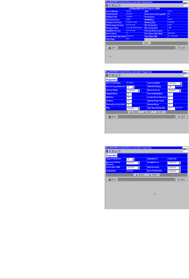
WebBIOS allows you to view information
for the LSI SAS controller. To view
the properties for the controller, click
Controller Properties on the main
WebBIOS screen. There are three
Controller Properties screens. The right
gure shows the rst screen.
The information on this screen is read-
only and cannot be modied directly. Most
of this information is self-explanatory. The
screen lists the number of virtual drives
that are already dened on this controller,
plus the number of drives connected to
the controller.
Click Next to view the second Controller
Properties screen, as shown in the right
gure.
Click Next to view the third Controller
Properties screen, as shown in the
following gure.
The following table describes the entries/options listed on the second and third
Controller Properties screen. We recommend that you leave these options at
their default settings to achieve the best performance, unless you have a specic
reason for changing them.
ASUS PIKE 2208 2-31
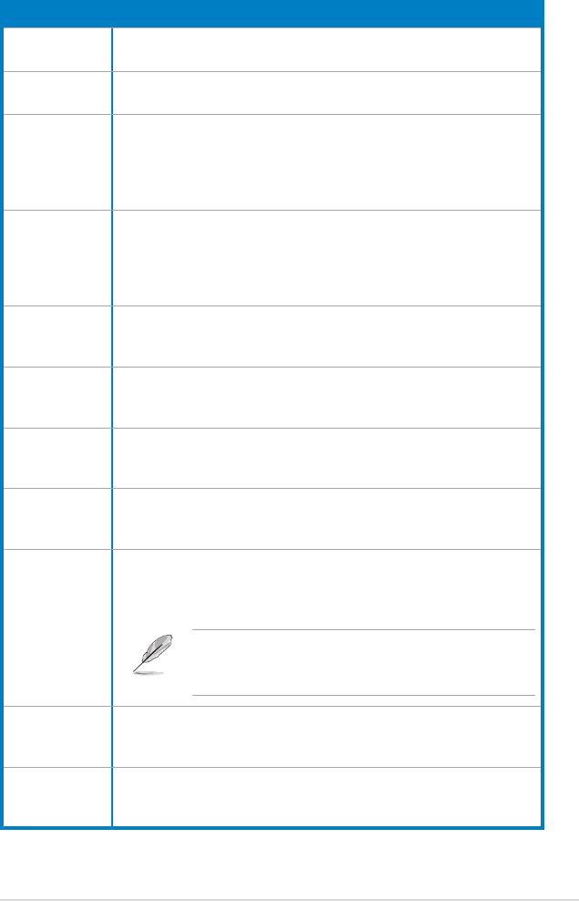
Controller Properties Menu Options
Option Description
Battery Backup This entry indicates whether the selected controller has a BBU. If
present, you can click Manage to view information about the BBU.
Set Factory
Defaults
Use this option to load the default MegaRAID® WebBIOS CU settings.
The default is No.
Cluster Mode
Use this option to enable or disable Cluster mode. The default is
Disabled. A cluster is a grouping of independent servers that can
access the same data storage and provide services to a common set
of clients. When Cluster mode is disabled, the system operates in
Standard mode.
Rebuild Rate
Use this option to select the rebuild rate for drives connected to the
selected controller. The default is 30 percent. The rebuild rate is the
percentage of system resources dedicated to rebuilding a failed drive.
The higher the number, the more system resources devoted to a
rebuild.
BGI Rate
Use this option to select the amount of system resources dedicated
to background initialization of virtual drives connected to the selected
controller. The default is 30 percent.
CC Rate
Use this option to select the amount of system resources dedicated
to consistency checks of virtual drives connected to the selected
contrroller. The default is 30 percent.
Reconstruction
Rate
Use this option to select the amount of system resources dedicated
to reconstruction of drives connected to the selected controller. The
default is 30 percent.
NCQ
Native Command Queuing (NCQ) gives an individual drive the ability to
optimize the order in which it executes the read and write commands.
The default is Enabled.
Coercion Mode
Drive coercion is a tool for forcing drives of varying capacities to the
same size so they can be used in a drive group. The coercion mode
options are None, 128MB-way, and 1GB-way. The default is 1GB-way.
The number you choose depends on how much the
drives from various vendors vary in their actual size. We
recommend that you use the 1GB coercion mode option.
S.M.A.R.T.
Polling
This option determines how frequently the controller polls for drives
reporting a predictive drive failure (S.M.A.R.T. error). The default is 300
seconds (5 minutes).
Alarm Control Select this option to enable, disable, or silence the onboard alarm tone
generator on the controller. The default is Enabled.

2-32 Chapter 2: RAID conguration
Controller Properties Menu Options (Cont.)
Option Description
Patrol Read
Rate
Use this option to select the rate for patrol reads for drives connected to
the selected controller. The default is 30 percent. The patrol read rate is
the percentage of system resources dedicated to running a patrol read.
Cache Flush
Interval
Use this option to control the interval (in seconds) at which the contents
of the onboard data cache are ushed. The default is 4 seconds.
Spinup Drive
Count
Use this option to control the number of drives that spin up
simultaneously. The default is 4 drives.
Spinup Delay
Use this option to control the interval (in seconds) between spinup of
drives connected to this controller. The delay prevents a drain on the
system’s power supply that would occur if all drives spun up at the
same time. The default is 12 seconds.
Stop CC on
Error
Use this option if you want to stop a consistency check when the
controller BIOS encounters an error. The default is No.
Maintain PD
Fail History
Use this option to maintain the history of all drive failures. The default
is Enabled.
Controller BIOS
Use this option to enable or disable the BIOS for the selected controller.
The default is Enabled. If the boot device is on the selected controller,
the BIOS must be enabled. Otherwise, the BIOS should be disabled or
it might not be possible to use a boot device elsewhere.
Link Speed
Use this option to change the link speed between the controller and
an expander or between the controller and a drive that is directly
connected to the controller.
Schedule CC “Supported” will be displayed if the controller supports consistency
check schedule.
StopOnError
Enable this option if you want the boot process to stop when the
controller BIOS encounters an error during boot-up. The default is
Enabled.
Disk Activity
Enable this option if you want to locate a particular disk. This disk can
be identied with a continuous blinking of green activity LED. This
works only if the disks are installed in an enclosure. The default is
Disabled.
If you make changes to the options on this screen, click Submit to register them. If
you change your mind, click Reset to return the options to their default values.
ASUS PIKE 2208 2-33
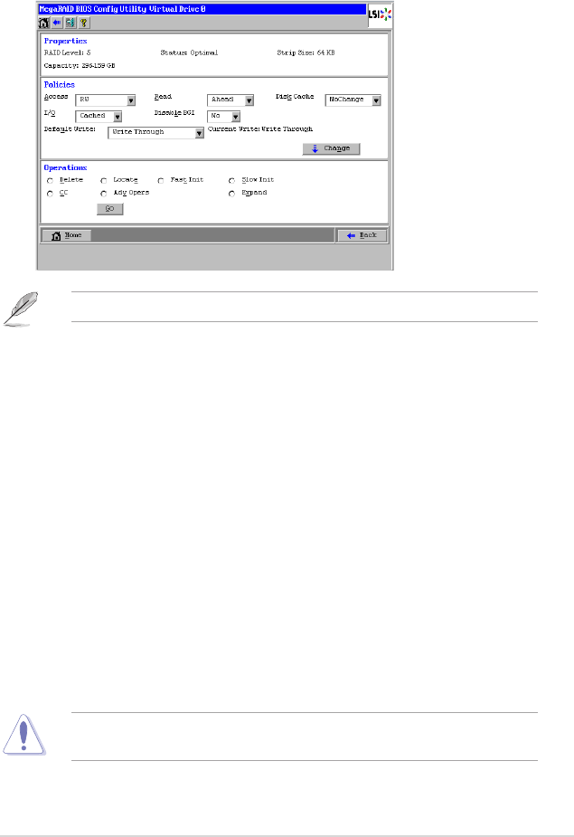
Viewing and Changing Virtual Drive Properties
To access the Virtual Drive screen, click a virtual drive icon in the right panel on the
WebBIOS CU main screen. The following gure shows the Virtual Drive screen.
The conguration items in the screen above vary with the existing RAID level.
The Properties panel of this screen displays the virtual drive’s RAID level, state,
capacity, and strip size.
The Policies panel lists the virtual drive policies that were dened when the
storage conguration was created. To change any of these policies, make a
selection from the drop-down menu, and click Change.
The Operations panel lists operations that can be performed on the virtual drive.
To perform an operation, select it, and click Go. Choose from the following options:
• Select Delete to delete this virtual drive.
• Select Locate to make the LEDs ash on the drives used by this virtual drive.
This works only if the drives are installed in a drive enclosure that supports
SCSI-Accessed-Fault-Tolerant-Enclosure (SAFTE).
• Select Fast Init or Slow Init to initialize this virtual drive. A fast initialization
quickly writes zeroes to the rst and last 10-MB regions of the new virtual drive
and then completes the initialization in the background. A slow initialization
is not complete until the entire virtual drive has been initialized with zeroes. It
is seldom necessary to use this option, because the virtual drive was already
initialized when you created it.
Before you run an initialization, back up any data on the virtual drive that you
want to save. All data on the virtual drive is lost when you initialize the drive.
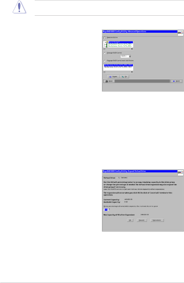
2-34 Chapter 2: RAID conguration
• Select CC to run a consistency check on this virtual drive.
Before you change a virtual drive conguration, back up any data on the virtual
drive that you want to keep.
• Select Adv Opers to set the advanced operations on this virtual drive.
1. Select either Change RAID
Level or Change RAID Level
and Add Drive.
◊ If you select Change RAID
Level, change the RAID level
from the drop-down menu.
◊ If you select Change RAID
Level and Add Drive,
change the RAID level from
the drop-down menu and
then select one or more
drives to add from the list of drives.
2. Click Go. When the message appears, conrm that you want to migrate
the RAID level of the virtual drive.
A reconstruction operation begins on the virtual drive. You must wait until
the reconstruction is completed before you perform any other tasks in
the WebBIOS CU.
• Select Expand to increase the size of a virtual drive to occupy the remaining
capacity in the drive group. In addition, you can add drives to the virtual drive
in order to increase capacity.
1. Enter the percentage of the
available capacity that you
want the virtual drive to use.
For example, if there are 100
GB of capacity available and
you want to increase the size
of the virtual drive by 30GB,
select 30 percent.
2. Click Calculate to determine
the capacity of the virtual drive
after expansion. Click Ok.
The virtual drive expands by the selected percentage of the available
capacity.
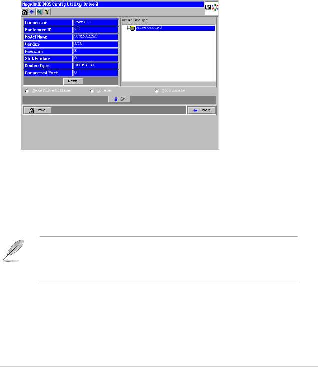
ASUS PIKE 2208 2-35
Viewing Drive Properties
The Physical Drive screen displays the properties of a selected drive and also
enables you to perform operations on the drive.
There are two ways to access the Physical Drive screen:
• On the main menu screen, click on a drive in the right panel under the heading
Physical View.
• On the main menu screen, click on Drives in the left panel to display the
Drives screen. Then click on a drive in the right panel. Click on the Properties
button, and click Go. The properties for the selected drive display.
The below gure shows the Physical Drive screen.
The drive properties are view-only and are self-explanatory. Note that the
properties include the state of the drive. The operations listed at the bottom of the
screen vary depending on the state of the drive. After you select an operation,
click Go to start the operation. If the drive state is Online, the following operations
appear.
• Select Make Drive Ofine if you want to force the drive ofine.
If you force ofine a good drive that is part of a redundant drive group with a hot
spare, the drive will rebuild to the hot spare drive. The drive you forced ofine
will go into the Uncongured Bad state. Access the BIOS utility to set the drive
to the Uncongured Good state.
• Select Locate to make the LED ash on the drive. This works only if the drive
is installed in a drive enclosure.
• Select Stop Locate to disable the LED ash on the drive.

2-36 Chapter 2: RAID conguration
If the drive state is Uncongured Good, four additional operations appear on this
screen:
• Select Make Global HSP to make a global hot spare, available to all of the
virtual drives.
• Select Enclosure Afnity so if there are drive failures present on a split
backplane conguration, then the hot spare will be used rst on the backplane
side that it resides in.
• Select Make Unconf Bad to make the drive state to become Uncongured
Bad.
• Select Prepare for Removal to prepare the drive for removal from the
enclosure.
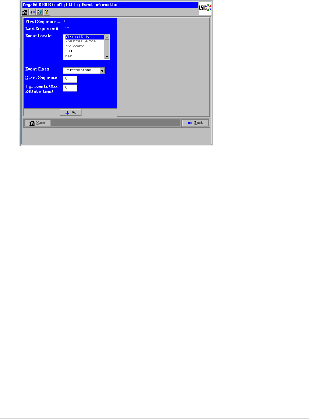
ASUS PIKE 2208 2-37
2.2.5 Viewing System Event Information
The SAS controller rmware monitors the activity and performance of all storage
congurations and devices in the system. When an event occurs (such as the
creation of a new virtual drive or the removal of a drive) an event message is
generated and is stored in the controller NVRAM. You can use the WebBIOS CU
to view these event messages. To do this, click Events on the main WebBIOS CU
screen. The Event Information screen appears, as shown in the following gure.
The right side of the screen is blank until you select an event to view. The First
Sequence and Last Sequence elds in the upper left of the screen show you how
many event entries are currently stored.
To view event information, follow these steps:
1. Select an event locale from the Event Locale drop-down menu. For
example, select Enclosure to view events relating to the drive enclosure.
2. Select an event class: Informational, Warning, Critical, Fatal, or Dead.
3. Enter a start sequence number, between the rst sequence and last
sequence numbers. The higher the number, the more recent the event.
4. Enter the Number of events of this type that you want to view, and click Go.
The rst event in the sequence appears in the right panel.
5. Click Next or Prev to page forward or backward through the sequence of
events.
6. If you want, select different event criteria in the left panel, and click Go again
to view a different sequence of events.
Each event entry includes a time stamp and a description to help you
determine when the event occurred and what it was.

2-38 Chapter 2: RAID conguration
2.2.6 Managing Congurations
This section includes information about maintaining and managing storage
congurations.
Running a Consistency Check
You should periodically run a consistency check on fault-tolerant virtual drives. A
consistency check veries that the redundancy data is correct and available for
RAID 1, RAID 5, RAID 6, RAID 10, RAID 50, and RAID 60 arrays. To do this, follow
these steps:
1. On the main WebBIOS CU screen, select a virtual drive.
2. When the Virtual Drive screen appears, select CC in the lower left panel, and
click Go.
3. Click Yes to continue. The consistency check begins.
If the WebBIOS CU nds a difference between the data and the parity value on
the redundant drive group, it assumes that the data is accurate and automatically
corrects the parity value. Be sure to back up the data before running a consistency
check if you think the data may be corrupted.
Deleting a Virtual Drive
You can delete any virtual drive on the controller if you want to reuse that space for
a new virtual drive. The WebBIOS CU provides a list of congurable drive groups
where there is a space to congure. If multiple virtual drives are dened on a single
drive group, you can delete a virtual drive without deleting the whole drive group.
Back up any data that you want to keep before you delete the virtual drive.
To delete a virtual drive, follow these steps:
1. On the main WebBIOS CU screen, select a virtual drive.
2. When the Virtual Drive screen appears, select Delete in the bottom panel
under the heading Operations, and click Go.
3. When the message appears, conrm that you want to delete the virtual drive.
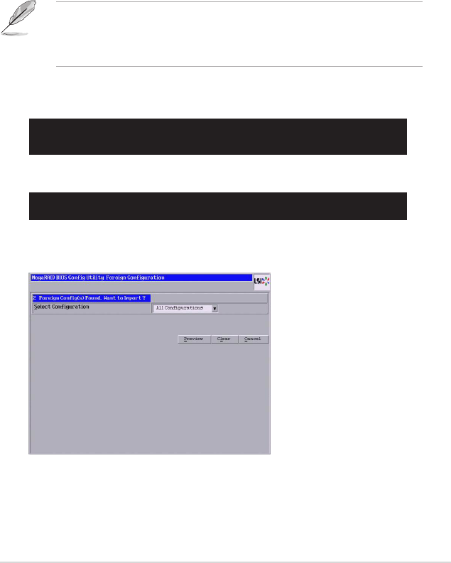
ASUS PIKE 2208 2-39
Importing or Clearing a Foreign Conguration
A foreign conguration is a storage conguration that already exists on a
replacement set of drives that you install in a computer system. In addition, if one
or more drives are removed from a conguration, by a cable pull or drive removal,
for example, the conguration on those drives is considered a foreign conguration
by the RAID controller.
The WebBIOS CU allows you to import the foreign conguration to the RAID
controller, or to clear the conguration so you can create a new conguration using
these drives.
When you create a new conguration, the WebBIOS CU shows only the
uncongured drives. Drives that have existing congurations, including foreign
congurations, do not appear. To use drives with existing congurations, you
must rst clear the conguration on those drives.
Foreign conguration(s) found on adapter
Press any key to continue or ‘C‘ to load the conguration utility,
or ‘F‘ to import foreign conguration(s) and continue.
If WebBIOS CU detects a foreign conguration, the following screen appears when
enter the WebBIOS CU.
If a foreign conguration is detected during POST, press <C> when the following
screen appears.
Follow these steps to import or clear a foreign conguration:
1. Click the drop-down list to show the congurations.
The GUID (Global Unique Identier) entries on the drop-down list are OEM
names and will vary from one installation to another.
1 Virtual Drive(s) handled by BIOS
Press <Ctrl><H> for WebBIOS or press <Ctrl><Y> for Preboot CLI
When the following screen appears, press <Ctrl+H> to enter the WebBIOS CU.
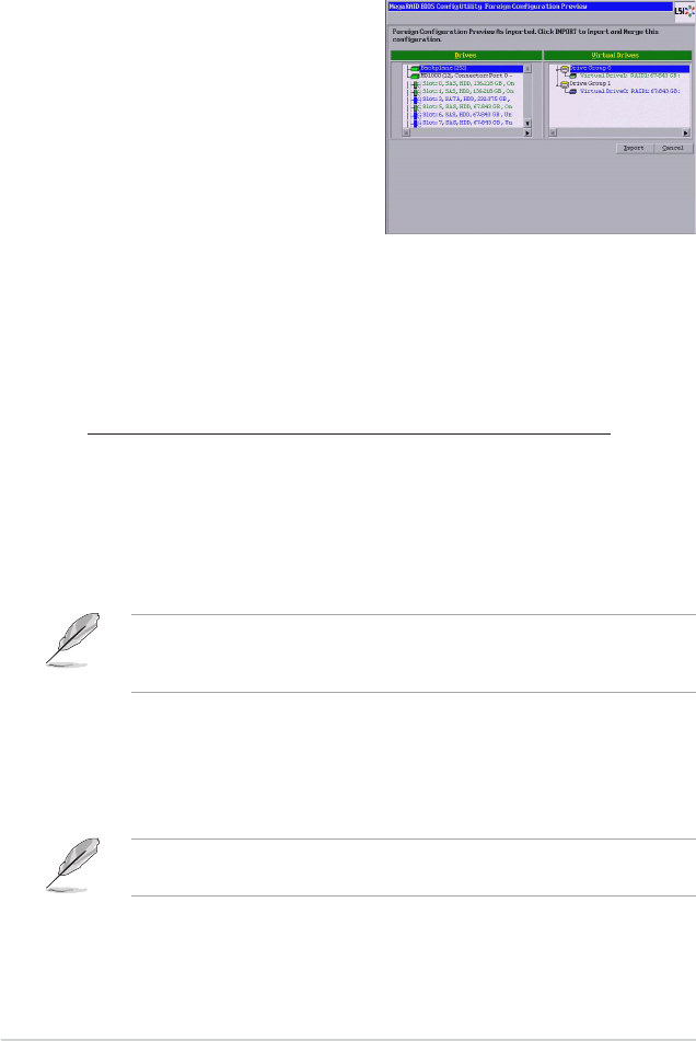
2-40 Chapter 2: RAID conguration
3. Perform one of the following steps:
• Click Preview to preview
the foreign congurations.
The Foreign Conguration
Preview screen appears, as
shown in the right gure.
• Click Clear to clear the foreign
congurations and reuse the
drives for another virtual drive.
If you click Cancel, it cancels the
importation or preview of the foreign
conguration.
The right panel shows the virtual drive properties of the foreign conguration.
In this example, there are two RAID1 virtual drives with 67.843GB each. The
left panel shows the drives in the foreign conguration.
4. Click Import to import this foreign conguration(s) and use it on this
controller.
Foreign Configurations in Cable Pull and Drive Removal Scenarios
If one or more drives are removed from a conguration, by a cable pull or
drive removal, for example, the conguration on those drives is considered a
foreign conguration by the RAID controller.
Use the Foreign Conguration Preview screen to import or clear the
foreign conguration in each case.
The following scenarios can occur with cable pulls or physical drive removals.
If you want to import the foreign conguration in any of the following scenarios,
you should have all the drives in the enclosure before you perform the import
operation.
1. Scenario #1: If all of the drives in a conguration are removed
and re-inserted, the controller considers the drives to have foreign
congurations.
Import or clear the foreign conguration. If you select Import, automatic
rebuilds will occur in redundant virtual drives.
Start a consistency check immediately after the rebuild is complete to ensure
data integrity for the virtual drives.
2. Select a conguration or All Congurations.

ASUS PIKE 2208 2-41
2. Scenario #2: If some of the drives in a conguration are removed
and re-inserted, the controller considers the drives to have foreign
congurations.
Import or clear the foreign conguration. If you select Import, automatic
rebuilds will occur in redundant virtual drives.
Start a consistency check immediately after the rebuild is complete to ensure
data integrity for the virtual drives.
3. Scenario #3: If all the drives in a virtual drive are removed, but at
different times, and re-inserted, the controller considers the drives to
have foreign congurations.
Import or clear the foreign conguration. If you select Import, all drives
that were pulled before the virtual drive became ofine will be imported
and then automatically rebuilt. Automatic rebuilds will occur in redundant
virtual drives.
4. Scenario #4: If the drives in a non-redundant virtual drive are removed,
the controller considers the drives to have foreign congurations.
Import or clear the foreign conguration. No rebuilds will occur after
the import operation because there is no redundant data to rebuild the
drives with.

2-42 Chapter 2: RAID conguration
2.3 MegaRAID Storage Manager
MegaRAID Storage Manager software enables you to congure, monitor, and
maintain storage congurations on LSI SAS controllers. The MegaRAID Storage
Manager graphical user interface (GUI) makes it easy for you to create and
manage storage congurations.
2.3.1 Hardware and Software Requirements
The hardware requirements for MegaRAID Storage Manager software are as
follows:
• PC-compatible computer with an IA-32 (32-bit) Intel Architecture processor or
an EM64T (64-bit) processor and at least 128 Mbytes of system memory (256
Mbytes recommended)
• Disk drive with at least 50 Mbytes available free space
Refer to your server documentation and to the operating system documentation for
more information on hardware and operating system requirements.
2.3.2 Installing MegaRAID Storage Manager Software on
Microsoft Windows OS
Follow these steps if you need to install MegaRAID Storage Manager software on
a system running Microsoft Windows OS:
1. Insert the ASUS PIKE 2208 Support CD in the optical disc drive. The CD
automatically displays the Utilities menu if Autorun is enabled in your
computer.
If Autorun is NOT enabled in your computer, browse the contents of the Support
CD to locate Setup.exe. Double-click Setup.exe to run the Support CD.
2. Click LSI MegaRAID Storage Manager.
3. When the Welcome screen appears, click Next.
If MegaRAID Storage Manager software is already installed on this system,
the Program Maintenance screen appears. Read the screen text and select
Modify, Repair, or Remove.
4. When the next screen appears, read and accept the user license, and click
Next.
The Customer Information screen appears, as shown in the following gure.
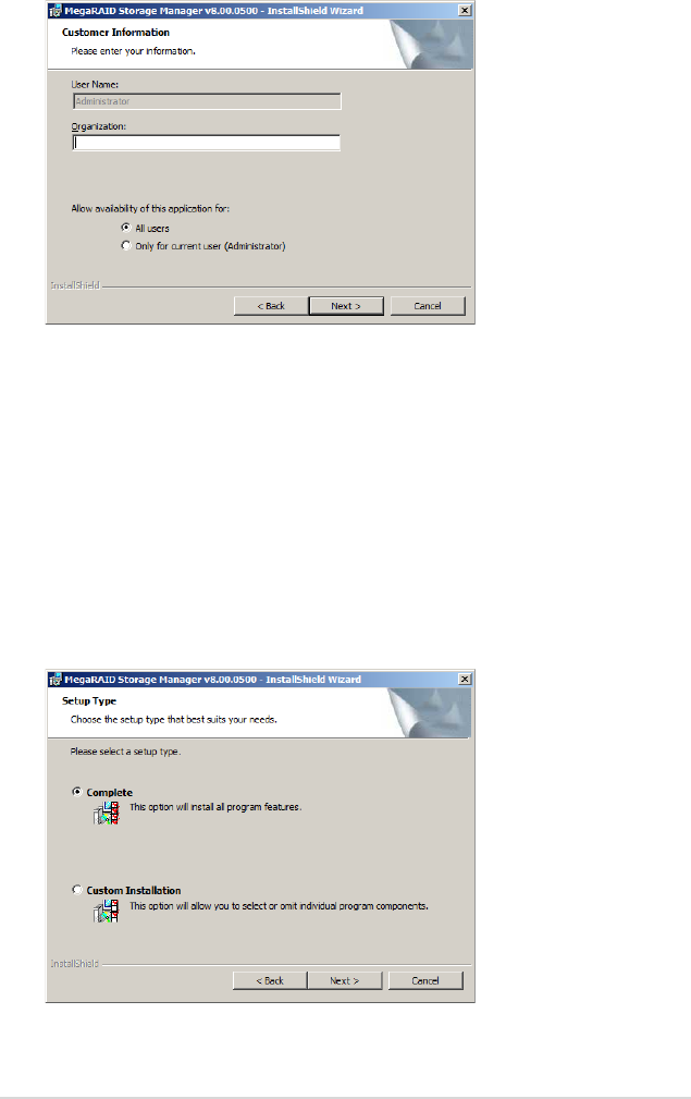
ASUS PIKE 2208 2-43
5. Enter your user name and organization name. In the bottom part of the
screen, select an installation option:
– If you select All users, any user with administrative privileges can use
this version of MegaRAID Storage Manager software to view or change
storage congurations.
– If you select Only for current user, the MegaRAID Storage Manager
shortcuts and associated icons will be available only to the user with this
user name.
6. Click Next to continue.
7. On the next screen, accept the default Destination Folder, or click Change to
select a different destination folder. Click Next to continue.
The Setup Type screen appears, as shown in the following gure.
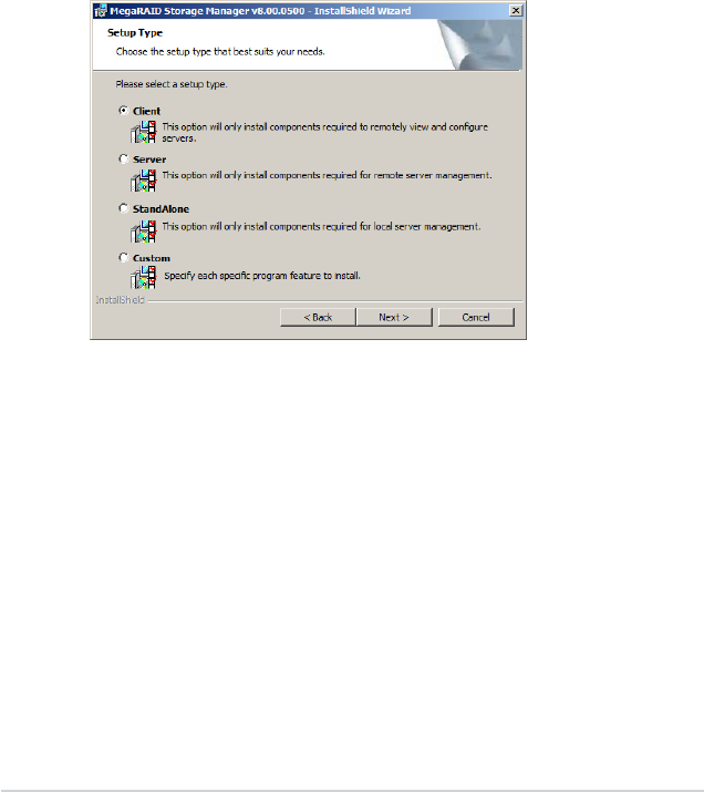
2-44 Chapter 2: RAID conguration
8. Select one of the Setup options. The options are fully explained in the screen
text.
– Normally, you would select Complete if you are installing MegaRAID
Storage Manager software on a server.
– Select Custom Installation if you want to select individual program
components.
9. Click Next to continue.
If you selected Custom Installation as your setup option, the second Setup
Type screen appears, as shown in the following gure.
If you select Complete as your setup option, the Installation Wizard is ready
to install MSM. To begin installation, click on Install on the next screen that
appears.
10. Select one of the custom setup options. The options are fully explained in the
screen text.
– Select Client if you are installing MegaRAID Storage Manager software
on a PC that will be used to view and congure servers over a network.
To begin installation, click on Install on the next screen that appears.
– Select Server to install only those components required for remote
server management. To begin installation, click on Install on the next
screen that appears.
– Select StandAlone if you will use MegaRAID Storage Manager
software to create and manage storage congurations on a standalone
workstation. To begin installation, click on Install on the next screen that
appears.
– Select Custom if you want to specify individual program features to
install.
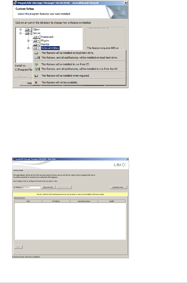
ASUS PIKE 2208 2-45
11. Click Next to proceed.
12. Click Install to install the program.
13. When the nal Conguration Wizard screen appears, click Finish.
If you select Client installation for a PC used to monitor servers, and if there
are no available servers with a registered framework on the local subnet
(that is, servers with a complete installation of MegaRAID Storage Manager
software), the server screen appears, as shown in the following gure. The
server screen will not list any servers. You can use this screen to manage
systems remotely.
If you select Custom, a window listing the installation features appears, as
shown in the following gure. Select the features you want on this screen.

2-46 Chapter 2: RAID conguration
2.3.3 Installing MegaRAID Storage Manager Software for
Linux
Follow these steps if you need to install MegaRAID Storage Manager software on
a system running Red Hat Linux or SUSE Linux:
1. Copy the MSM_linux_installer...tar.gz le to a temporary folder.
2. Untar the MSM_linux_installer...tar.gz le using the following command:
tar -zxvf MSM_linux_installer...tar.gz
A new disk directory is created.
3. Go to the new disk directory.
4. In the disk directory, nd and read the readme.txt le.
5. To start the installation, enter the following command:
csh install.sh -a
If you select Client installation for a PC used to monitor servers, and if there are no
available servers with a registered framework on the local subnet (that is, servers
with a complete installation of MegaRAID Storage Manager software), the server
screen appears. The server screen does not list any servers. You can use this
screen to manage systems remotely.

ASUS PIKE 2208 2-47
2.3.4 Linux Error Messages
The following messages may appear while you are installing MegaRAID Storage
Manager software on a Linux system:
• More than one copy of MegaRAID Storage Manager software has been
installed.
This message indicates that the user has installed more than one copy of
MegaRAID Storage Manager software. (This can be done by using the rpm-
force command to install the rpm le directly, which is not recommended,
instead of using the install.sh le.) In such cases, the user must uninstall all the
rpm les manually before installing MegaRAID Storage Manager software with
the procedure listed previously.
• The version is already installed.
This message indicates that the version of MegaRAID Storage Manager
software you are trying to install is already installed on the system.
• The installed version is newer.
This message indicates that a version of MegaRAID Storage Manager
software is already installed on the system, and it is a newer version than the
version you are trying to install.
• Exiting installation.
This is the message that appears when the installation is complete.
• RPM installation failed.
This message indicates that the installation failed for some reason. Additional
message text explains the cause of the failure.
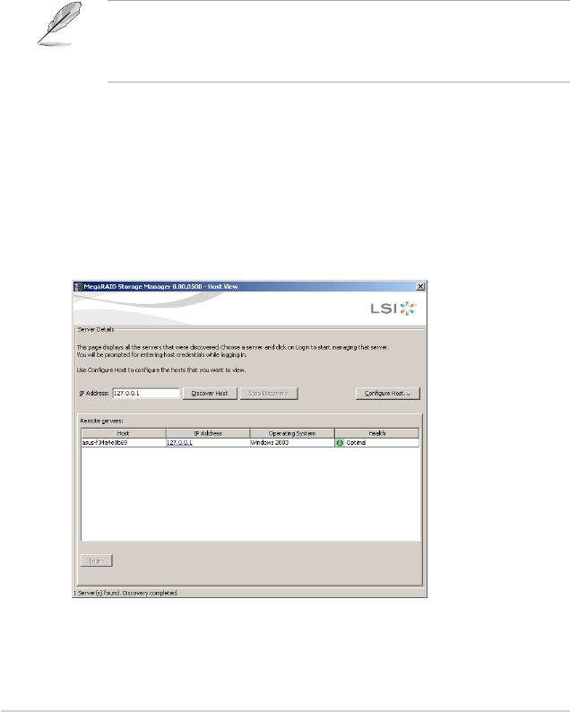
2-48 Chapter 2: RAID conguration
2.3.5 Starting the MegaRAID Storage Manager Software
Follow these steps to start the MegaRAID Storage Manager software and view the
main window:
1. Start the program using the method required for your operating system
environment:
– To start MegaRAID Storage Manager software on a Microsoft Windows
system, select Start > All Programs > MegaRAID Storage Manager >
StartupUI, or double-click the MegaRAID Storage Manager shortcut on
the desktop.
If a warning appears stating that Windows Firewall has blocked some features
of the program, click Unblock to allow the MegaRAID Storage Manager
software to start. (The Windows Firewall sometimes blocks the operation of
programs that use Java.)
– To start MegaRAID Storage Manager software on a Red Hat Linux
system, select Applications > System Tools > MegaRAID Storage
Manager StartupUI.
– To start MegaRAID Storage Manager software on a SUSE SLES
system, select Start > System > More Programs > MegaRAID Storage
Manager.
2. When the program starts, the select server window appears, as shown in the
following gure.
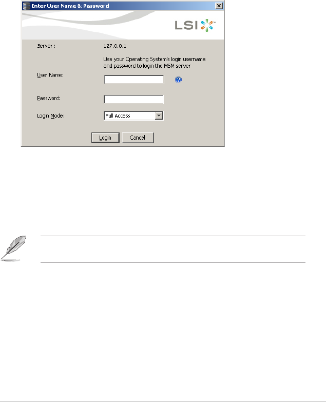
ASUS PIKE 2208 2-49
4. Select an access mode from the drop-down menu.
– Select Full Access if you need to both view the current conguration
and change the conguration.
– Select View Only if you need to only view and monitor the conguration.
5. Enter your user name and password, and click Login.
If the computer is networked, this is the login to the computer itself, not the
network login.
You must enter the root/administrator user name and password to use Full
Access mode. If your user name and password are correct for the Login
mode you have chosen, the main MegaRAID Storage Manager window
appears.
If the circle in Health column of the corresponding server is orange instead of
green, it means that the server is running in a degraded state—for example,
because a drive used in a virtual drive has failed. If the circle is red, the
storage conguration in the server has failed.
You can click Congure Host if you want to select the display preferences
for the server. You can choose to display only the local server, systems from
a list, or display all of the systems in the network of the local server.
3. Double-click the icon of the server that you want to access. The server login
window appears, as shown in the following gure.
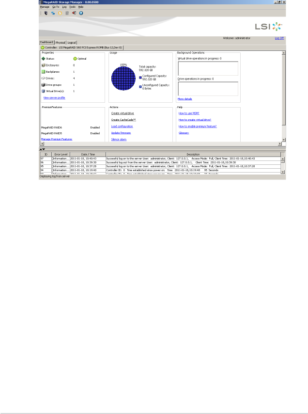
2-50 Chapter 2: RAID conguration
2.3.6 MegaRAID Storage Manager Window
After you log in, the dashboard view provides an overview of the system and
covers the properties of the virtual drives and the physical drives, total capacity,
congured capacity, uncongured capacity, background operations in progress,
MegaRAID Storage Manager features and their status (enabled or disabled),
and actions you can perform, such as creating a virtual drive and updating the
rmware, as shown in the following gure.
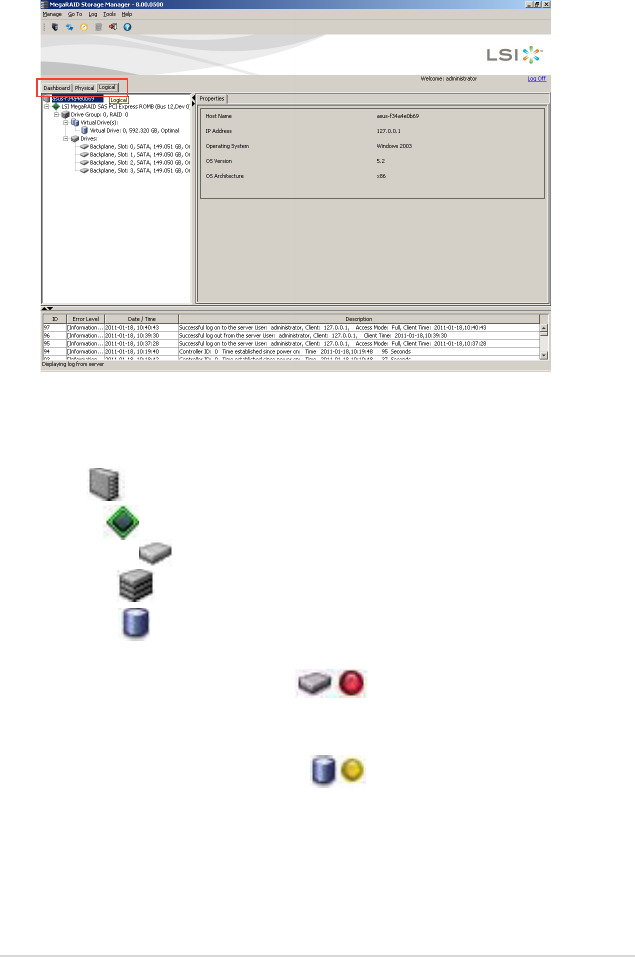
ASUS PIKE 2208 2-51
The following icons in the left panel represent the controllers, drives, and other
devices:
• System
• Controller
• Slot for a drive
• Drive group
• Virtual drive
A red circle to the right of an icon indicates that the device has failed. For example,
this icon indicates that a drive has failed: .
A yellow circle to the right of an icon indicates that a device is running in a
degraded state. For example, this icon indicates that a virtual drive is running in a
degraded state because a drive has failed: .
You can click the Physical tab to view the drives connected to the controller or
Logical tab to view the virtual drives connected to the controller.

2-52 Chapter 2: RAID conguration
Properties View Panel
The right panel of the MegaRAID Storage Manager window has the Properties
tab that displays information about the selected device. For example, if a controller
icon is selected in the left panel, the Properties tab lists information such as the
controller name, NVRAM size, and device port count.
Event Log Panel
The lower part of the MegaRAID Storage Manager window displays the system
event log entries. New event log entries appear during the session. Each entry has
an ID, a timestamp and date, an error level indicating the severity of the event, and
a brief description of the event.
Menu Bar
Here are brief descriptions of the main selections on the MegaRAID Storage
Manager menu bar.
Manage Menu
The Manage menu has an Exit option for exiting from the MegaRAID
Storage Manager software. It also has a Refresh option for updating the
display in the MegaRAID Storage Manager window. (Refresh is seldom
required; the display normally updates automatically.)
The Manage menu options also include Check Consistency, Initialize, and
Show Progress.
Go To Menu
The Go To menu is available when a controller, physical drive, or virtual disk
is selected in the MegaRAID Storage Manager window. The Go To menu
options vary depending on what type of device is selected in the left panel of
the MegaRAID Storage Manager window. For example, the Scan Foreign
Conguration option is available only when a controller is selected. The
options also vary depending on the current state of the selected device. For
example, if you select an ofine physical drive, the Make Drive Online option
will be available in the Go To menu.
Log Menu
The Log menu includes options for saving and clearing the message log.
Tools Menu
On the Tools menu you can select Congure Alerts to access the Event
Conguration Notication screen, which you can use to set the alert delivery
rules, event severity levels, exceptions, and email settings.

ASUS PIKE 2208 2-53
Help Menu
On the Help menu you can select Help > Contents to view the MegaRAID
Storage Manager online help le. You can select Help > About MegaRAID
Storage Manager to view version information for the MegaRAID Storage
Manager software.
• When you use the MegaRAID Storage Manager online help, you may see a
warning message that Internet Explorer has restricted the le from showing
active content. If this warning appears, click on the active content warning
bar and enable the active content.
• If you are using the Linux operating system, you must install Firefox® or
Mozilla® for the MegaRAID Storage Manager online help to display.

2-54 Chapter 2: RAID conguration
3
Chapter 3: Driver
installation
This chapter provides instructions for
installing the RAID drivers on different
operating systems.
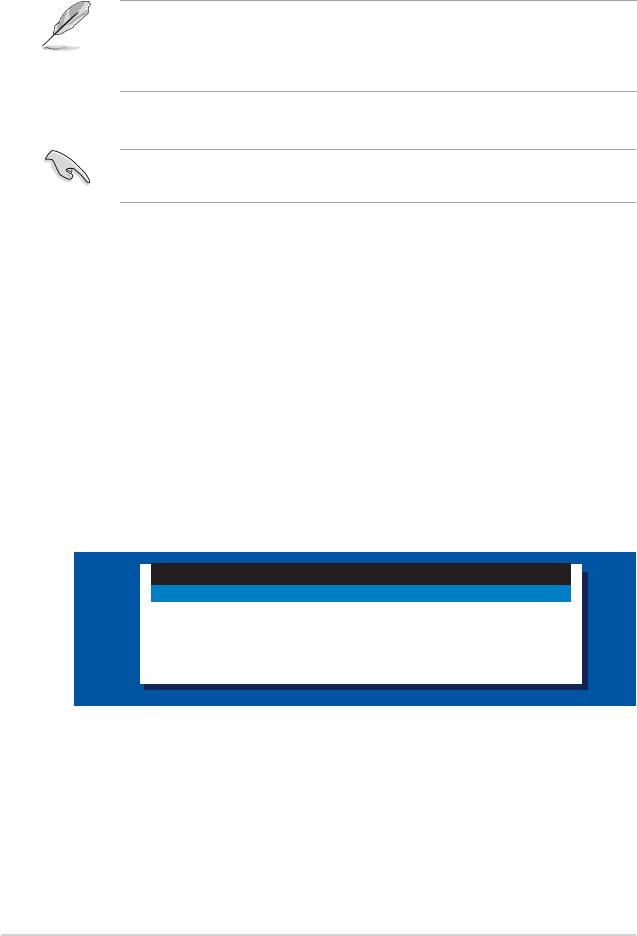
3-2 Chapter 3: Driver installation
3.1 RAID driver installation
After creating the RAID sets for your server system, you are now ready to install
an operating system to the independent hard disk drive or bootable array. This part
provides instructions on how to install or update the RAID card drivers.
The RAID card driver might be included in the Linux OS installation CD, and
could be loaded automatically during OS installation. However, we recommend
using the RAID driver packaged in the RAID card support CD for better
reliability.
Creating a RAID driver disk
You may have to use another system to create the RAID driver disk from the
RAID card support CD or from the Internet.
A oppy disk with the RAID driver is required when installing Windows® Server
2003 or Linux operating system on a hard disk drive that is included in a RAID set.
You can create a RAID driver disk in DOS (using the Makedisk application in the
support CD).
To create a RAID driver disk in DOS environment:
1. Place the RAID card support CD in the optical drive.
2. Restart the computer, then enter the BIOS Setup.
3. Select the optical drive as the rst boot priority to boot from the support CD.
Save your changes, then exit the BIOS Setup.
4. Restart the computer.
5. The Make Disk menu appears. SelectThe Make Disk menu appears. Select PIKE 2208 SAS2 card Driver, and press
<Enter> to enter the sub-menu.
Create Driver Diskette Menu
PIKE 2208 SAS2 card Driver
PIKE 2108 / PIKE 2108-32PD SAS2 card Driver
PIKE 2008/IMR SAS2 card Driver
PIKE 2008 SAS2 card Driver
FreeDOS command prompt

ASUS PIKE 2208 3-3
7. Place a blank, high-density oppy disk to the oppy disk drive.
8. Press <Enter>.
9. Follow screen instructions to create the driver disk.
6. Use the arrow keys to select the type of RAID driver disk you want to create.
PIKE 2208 SAS2 card Driver
Windows XP 32 bit
Windows XP 64 bit
Windows Server 2003 32 bit
Windows Server 2003 64 bit
Windows Vista 32 bit
Windows Vista 64 bit
Windows Server 2008 32 bit
Windows Server 2008 64 bit
Windows 7 32 bit
Windows 7 64 bit
Windows Server 2008 R2 64 bit
RHEL 4 UP7 32/64 bit
RHEL 4 UP8 32/64 bit
RHEL 4 UP9 32/64 bit
RHEL 5 UP2 32/64 bit
RHEL 5 UP3 32/64 bit
RHEL 5 UP4 32/64 bit
RHEL 5 UP5 32/64 bit
RHEL 5 UP6 32/64 bit
RHEL 5 UP7 32/64 bit
RHEL 5 UP8 32/64 bit
SLES 9 SP2 32 bit
3-4 Chapter 3: Driver installation
3.2 Windows® Server 2003 OS Driver
Installation
3.2.1 During Windows® Server 2003 OS installation
To install the RAID card driver when installing Windows® Server 2003 OS:
1. Boot the computer using the Windows® Server 2003 OS installation CD. The
Window® Setup starts.
2. Press <F6> when the message “Press F6 if you need to install a third party
SCSI or RAID driver...” appears at the bottom of the screen.
3. The next screen appears. Press <S> to specify an additional device.
Windows Setup
S=Specify Additional Device ENTER=Continue F3=Exit
Setup could not determine the type of one or more mass storage devices
installed in your system, or you have chosen to manually specify an adapter.
Currently, Setup will load support for the following mass storage devices(s):
<none>
* To specify additional SCSI adapters, CD-ROM drives, or special
disk controllers for use with Windows, including those for
which you have a device support disk from a mass storage device
manufacturer, press S.
* If you do not have any device support disks from a mass storage
device manufacturer, or do not want to specify additional
mass storage devices for use with Windows, press ENTER.
Windows Setup
Press F6 if you need to install a third party SCSI or RAID driver...
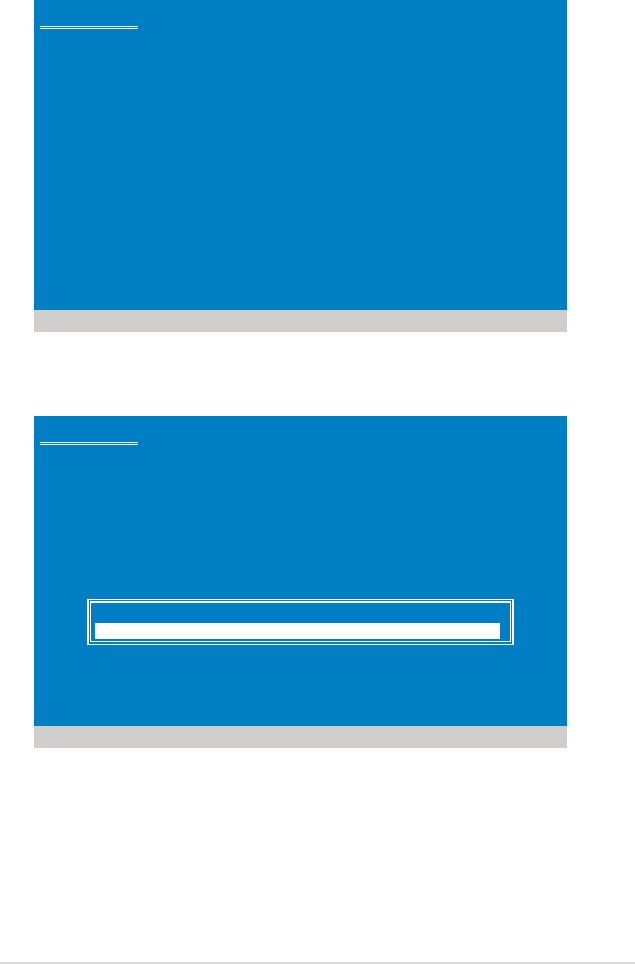
ASUS PIKE 2208 3-5
4. Insert the RAID driver disk you created earlier to the oppy disk drive, then
press <Enter>.
Windows Setup
ENTER=Continue ESC=Cancel F3=Exit
Please insert the disk labeled
Manufacturer-supplied hardware support disk
into Drive A:
* Press ENTER when ready.
5. Select LSI MegaRAID SAS RAID Controller Driver (Server 2003), and then
press <Enter>.
6. The Windows® Setup loads the RAID card drivers from the RAID driver disk.
When next screen appears, press <Enter> to continue installation.
7. Setup then proceeds with the OS installation. Follow screen instructions to
continue.
Windows Setup
ENTER=Select F3=Exit
You have chosen to congure a SCSI Adapter for use with Windows,
using a device support disk provided by an adapter manufacturer.
Select the SCSI Adapter you want from the following list, or press ESC
to return to the previous screen.
LSI MegaRAID SAS RAID Controller Driver (Windows 2000)
LSI MegaRAID SAS RAID Controller Driver (Server 2003 32-bit)
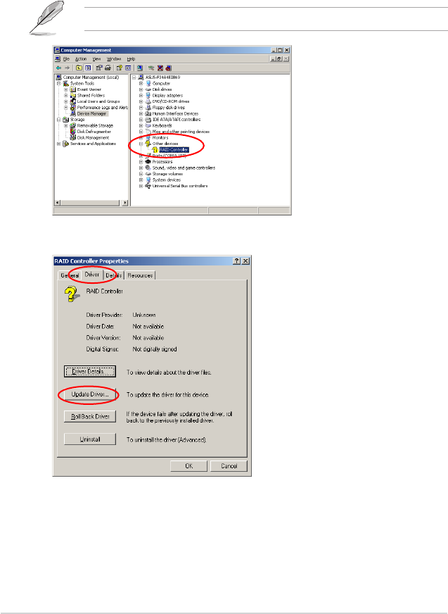
3-6 Chapter 3: Driver installation
3.2.2 After Windows® Server 2003 OS installation
To update the RAID card driver after installing Windows® Server 2003 OS:
1. Click Start, right-click My Computer and select Manage from the menu.
2. In the Computer Management window, click the Device Manager item.
3. Double-click RAID Controller under the Other Devices item.
4. Click the Driver tab on the top, then click Update Driver.
The controller name differs according to the installed SAS RAID card.
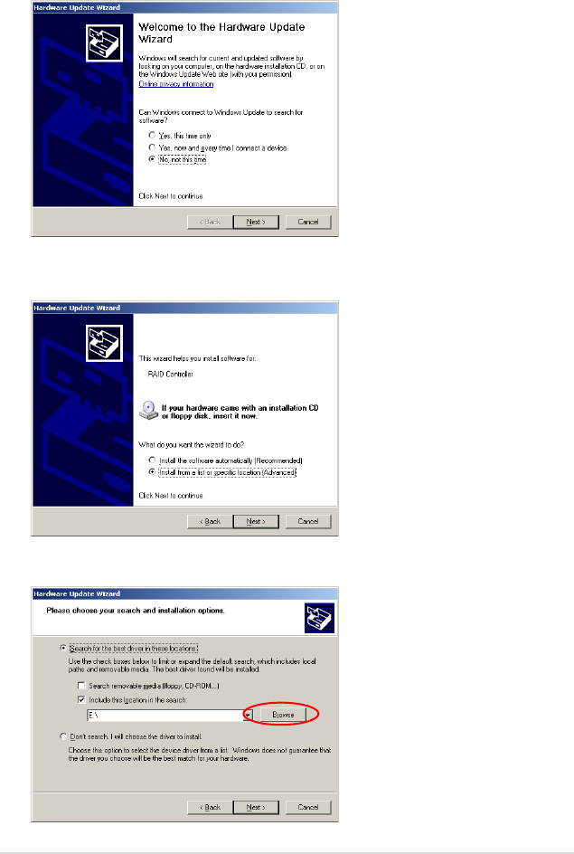
ASUS PIKE 2208 3-7
5. Toggle No, Not this time to cancel searching driver from Windows Update,
and then click Next to continue.
6. Toggle Install from a list or specic location (Advanced), then click Next
to continue.
7. Select the Include this location in the search: check box, and then click
Browse.
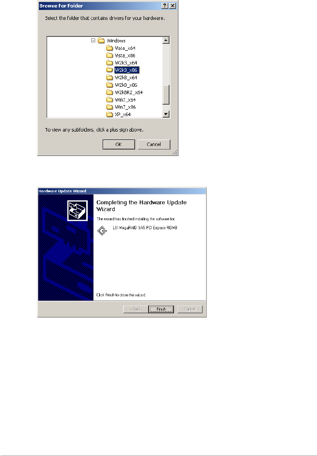
3-8 Chapter 3: Driver installation
7. Insert the SAS RAID card Support CD into the optical drive.
8. Locate the driver in the corresponding folder of the Support CD, and then
click OK to continue.
9. The system automatically updates the driver. After completing driver update,
click Finish to close the wizard.
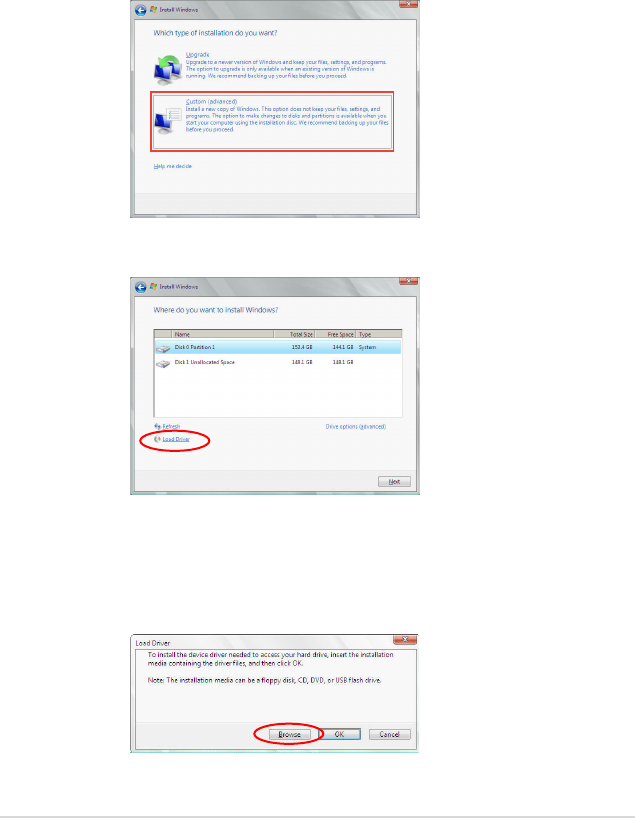
ASUS PIKE 2208 3-9
3. Click Load Driver.
4. A message appears, reminding you to insert the installation media containing
the driver of the SAS RAID card. If you have only one optical drive installed
in your system, eject the Windows OS installation disc and replace with the
PIKE SAS RAID card Support CD into the optical drive. Click Browse to
continue.
3.3 Windows® Server 2008 OS Driver
Installation
3.3.1 During Windows® Server 2008 OS installation
To install the RAID card driver when installing Windows® Server 2008 OS:
1. Boot the computer using the Windows® Server 2008 OS installation disc.
Follow the screen instructions to start installing Windows Server 2008.
2. When prompted to choose a type of installation, click Custom (advanced).
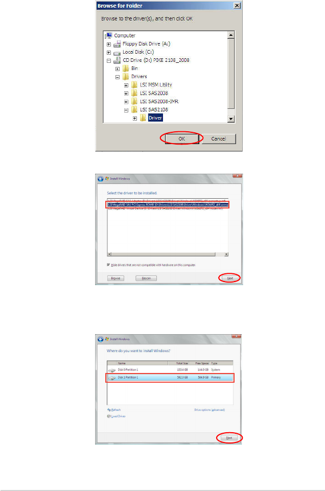
3-10 Chapter 3: Driver installation
5. Locate the driver in the corresponding folder of the Support CD, and then
click OK to continue.
6. Select LSI MegaRAID SAS PCI Express ROMB and click Next.
8. Setup then proceeds with the OS installation. Follow screen instructions to
continue.
7. When the system nishes loading the RAID driver, replace the SAS RAID
card Support CD with the Windows Server installation disc. Select the drive
to install Windows and click Next.
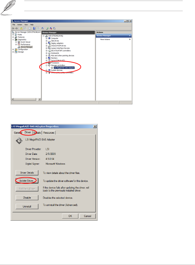
ASUS PIKE 2208 3-11
4. Click the Driver tab on the top, then click Update Driver.
3.3.2 After Windows® Server 2008 OS installation
To update the RAID card driver after installing Windows® Server 2008 OS:
1. Click Server Manager on the Windows taskbar. In the Server Manager
window, click the “+” sign before Diagnostics and click Device Manager.
Click the “+” sign before Storage controllers, and double-click LSI
MegaRAID SAS Adapter.
The controller name differs according to the installed SAS RAID card.
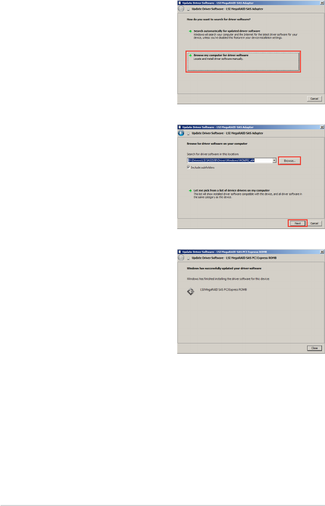
3-12 Chapter 3: Driver installation
5. Click Browse my computer for
driver software.
9. The system automatically updates
the driver. After completing driver
update, click Close to exit the
wizard.
6. Insert the SAS RAID card Support
CD into the optical drive. Click
Browse.
7. In the Browse for Folder
window, locate the driver in the
corresponding folder of the Support
CD, and then click OK to continue.
8. In the Update Driver Software
window, click Next to continue.
ASUS PIKE 2208 3-13
3.4 Red Hat® Enterprise Linux OS 5 Driver
Installation
To install the RAID card driver when installing Red Hat Red Hat® Enterprise OS:
1. Boot the system from the Red Hat® OS installation CD.
2. At the boot:, type linux dd, then press <Enter>.
- To install or upgrade in graphical mode, press the <ENTER> key.
- To install or upgrade in text mode, type: linux text <ENTER>.
- Use the function keys listed below for more information.
[F1-Main] [F2-Options] [F3-General] [F4-Kernel] [F5-Rescue]
boot: linux dd
3. Select Yes using the <Tab> key when asked if you have the driver disk, then
press <Enter>.
Main Menu
Do you have a driver disk?
Yes No
4. Insert the Red Hat® Enterprise RAID driver disk to the USB oppy disk drive,
select OK, then press <Enter>.
The drivers for the RAID card are installed to the system.
Insert Driver Disk
Insert your driver disk into /dev/sda
and press “OK” to continue.
OK Back
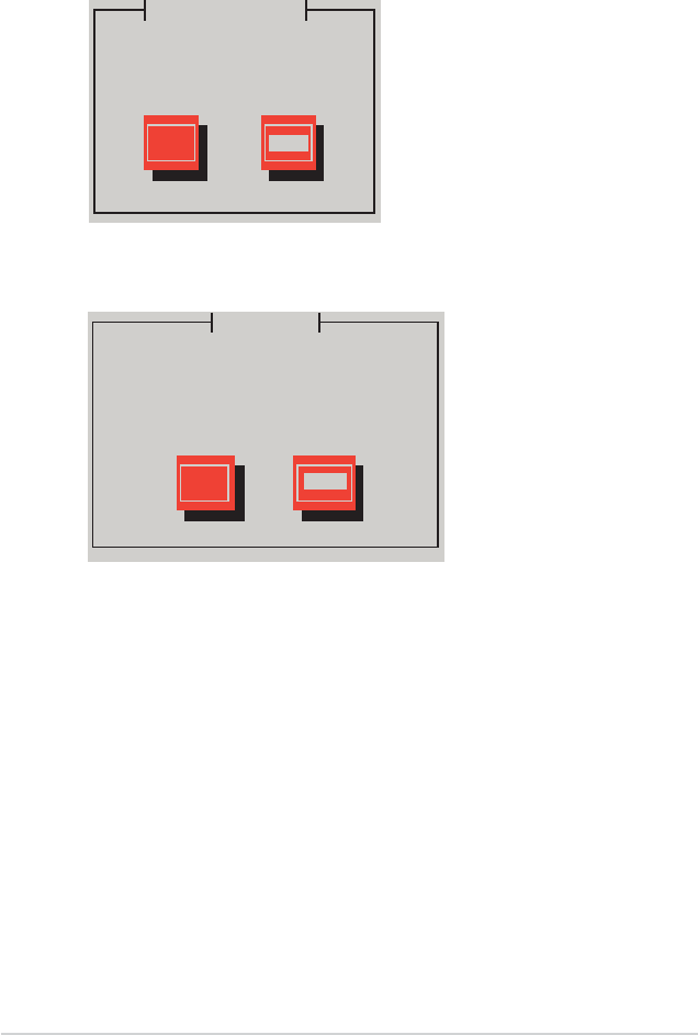
3-14 Chapter 3: Driver installation
5. When asked if you will load additional RAID controller drivers, select No, then
press <Enter>.
7. Follow the screen instructions to continue the OS installation.
More Driver Disks?
Do you wish to load any more
driver disks?
Yes No
6. Select Skip and press <Enter> to continue.
CD Found
To begin testing the CD media before
installation press OK.
Choose Skip to skip the media test
and start the installation.
OK Skip
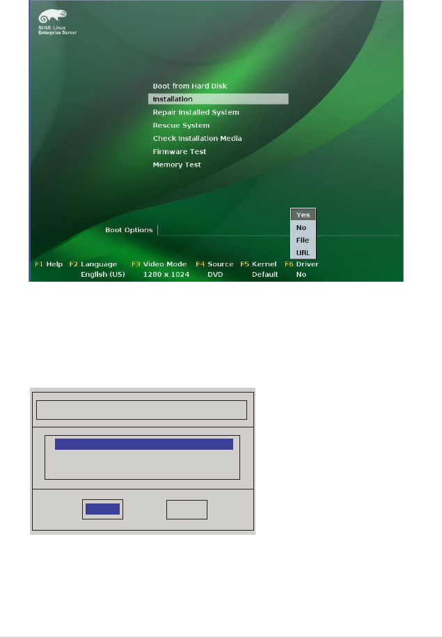
ASUS PIKE 2208 3-15
3.5 SUSE® Linux OS 11 Driver Installation
To install the RAID card driver when installing SUSE Linux Enterprise Server OS: SUSE Linux Enterprise Server OS:
1. Boot the system from the SUSE OS installation CD.
2. Use the arrow keys to select Installation from the Boot Options menu.
3. Press <F6>, then select Yes from the menu. Press <Enter>.
4. Insert the RAID driver disk to the USB oppy disk drive. Ensure that Installation
from the Boot Options menu is selected, then press <Enter>.
5. When below screen appears, select the USB oppy disk drive (sdx) as the
driver update medium. Select OK, then press <Enter>.
The drivers for the RAID controller are installed to the system.
Please choose the Driver Update medium.
OK Back
sda: USB Floppy
sr0: CD-ROM, ASUS DRW-2014S1T
Other device

3-16 Chapter 3: Driver installation
ASUS contact information
ASUSTeK COMPUTER INC.
Address 15 Li-Te Road, Peitou, Taipei, Taiwan 11259
Telephone +886-2-2894-3447
Fax +886-2-2890-7798
E-mail info@asus.com.tw
Web site www.asus.com.tw
Technical Support
Telephone +86-21-38429911
Online support support.asus.com
ASUS COMPUTER INTERNATIONAL (America)
Address 800 Corporate Way, Fremont, CA 94539, USA
Telephone +1-510-739-3777
Fax +1-510-608-4555
Web site usa.asus.com
Technical Support
Telephone +1-812-282-2787
Support fax +1-812-284-0883
Online support support.asus.com
ASUS COMPUTER GmbH (Germany and Austria)
Address Harkort Str. 21-23, D-40880 Ratingen, Germany
Fax +49-2102-959911
Web site www.asus.de
Online contact www.asus.de/sales
Technical Support
Telephone (Component) +49-1805-010923*
Telephone (System/Notebook/Eee/LCD) +49-1805-010920*
Support Fax +49-2102-9599-11
Online support support.asus.com
* EUR 0.14/minute from a German xed landline; EUR 0.42/minute from a mobile phone.
EC Declaration of Conformity
We, the undersigned,
Manufacturer: ASUSTek COMPUTER INC.
Address, City: No. 150, LI-TE RD., PEITOU, TAIPEI 112, TAIWAN R.O.C.
Country: TAIWAN
Authorized representative in Europe: ASUS COMPUTER GmbH
Address, City: HARKORT STR. 21-23, 40880 RATINGEN
Country: GERMANY
declare the following apparatus:
Product name : RAID Card
Model name : PIKE 2208
conform with the essential requirements of the following directives:
2004/108/EC-EMC Directive
EN 55022:2010
EN 61000-3-2:2006
EN 55013:2001+A1:2003+A2:2006
EN 55024:2010
EN 61000-3-3:2008
EN 55020:2007+A11:2011
1999/5/EC-R &TTE Directive
EN 300 328 V1.7.1(2006-10)
EN 300 440-1 V1.6.1(2010-08)
EN 300 440-2 V1.4.1(2010-08)
EN 301 511 V9.0.2(2003-03)
EN 301 908-1 V4.2.1(2010-03)
EN 301 908-2 V3.2.1(2007-05)
EN 301 893 V1.4.1(2005-03)
EN 302 544-2 V1.1.1(2009-01)
EN 50360:2001
EN 50371:2002
EN 50385:2002
EN 301 489-1 V1.9.2(2011-09)
EN 301 489-3 V1.4.1(2002-08)
EN 301 489-4 V1.3.1(2002-08)
EN 301 489-7 V1.3.1(2005-11)
EN 301 489-9 V1.4.1(2007-11)
EN 301 489-17 V2.1.1(2009-05)
EN 301 489-24 V1.5.1(2010-09)
EN 302 326-2 V1.2.2(2007-06)
EN 302 326-3 V1.3.1(2007-09)
EN 301 357-2 V1.3.1(2006-05)
EN 302 623 V1.1.1(2009-01)
2006/95/EC-LVD Directive
EN 60950-1 / A11:2009
EN 60950-1 / A12:2011
EN 60065:2002+A1:2006+A11:2008
EN 60065:2002 / A12:2011
2009/125/EC-ErP Directive
Regulation (EC) No. 1275/2008
EN 62301:2005
Regulation (EC) No. 642/2009
EN 62301:2005
Regulation (EC) No. 278/2009
EN 62301:2005
Ver. 120601
CE marking
Declaration Date: Jul. 27, 2012
Year to begin affixing CE marking:2012
Position : CEO
Name : Jerry Shen
Signature : __________
(
EC conformit
y
markin
g)
DECLARATION OF CONFORMITY
Per FCC Part 2 Section 2. 1077(a)
Responsible Party Name:
Asus Computer International
Address: 800 Corporate Way, Fremont
, CA 94539.
Phone/Fax No: (510)739-3777/(510)608-4555
hereby declares that the product
Product Name : RAID Card
Model Number : PIKE 2208
Conforms to the following specifications:
FCC Part 15, Subpart B, Unintentional Radiators
Supplementary Information:
This device complies with part 15 of the FCC Rules. Operation is subject to
the following two conditions: (1) This device may not cause harmful
interference, and (2) this device must accept any interference received,
including interference that may cause undesired operation.
Representative Person’s Name : Steve Chang / President
Signature :
Date : Jul. 27, 2012
Ver. 120601
