Atlas Copco BLM s r l F6X Controller Unit For MWR Wrenches User Manual Focus 60 Focus 61 User Guide
SALTUS Industrial Technique GmbH Controller Unit For MWR Wrenches Focus 60 Focus 61 User Guide
Users manual

User Guide
Focus 60 / Focus 61
Atlas Copco Industrial Technique AB
9839 0211 01
2017-01
Edition 1.1

Focus 60 / Focus 61 User Guide Revision history
9839 0211 01 Edition 1.1 3 (106)
Revision history
Edition
Date
Author
Description
Reference
Minimum
Software version
(ToolsTalk BLM)
Reference
Firmware
version
1.0
11 October
2016
C. Pacente
First issue
10.0.0
5.5.0.x
1.1
13 January
2017
C. Pacente
Specifications updated (par. 1.3), System
Overview updated (chapter 2), Focus 60 / Focus
61 Ethernet Ports updated (par. 4.4), Focus 60 /
Focus 61 Barcode Scanner Interface (RS232)
updated (par. 4.5), Focus 60 / Focus 61 I/O BUS
(CAN) updated (par. 4.6), Focus 60 / Focus 61
Wave Flexible Antenna updated (par. 4.7),
Software Installation updated (par. 5.1), Pset
Configuration updated (par. 6.3), I/O Accessories
updated (par. 6.6), Results Viewer updated
(chapter 9), CBP added (chapter 13)
10.1.0
5.5.1.x
Copyright Atlas Copco Industrial Technique AB
NOTE: This User Guide may be altered without further notice.
For further information log on to the Atlas Copco website: www.atlascopco.com
NOTE: The programming software (ToolsTalk BLM) may be updated with no changes
regarding the Focus 60 / Focus 61 functionalities.
The Reference Firmware version requires a specific Software version (for further details refer to
the above “Revision history” table).
NOTE: In case of conflicts between translations of this User Guide, always refer to the official
English version.

Table of Contents Focus 60 / Focus 61 User Guide
4 (106) 9839 0211 01 Edition 1.1
Table of Contents
Table of Contents ..................................................................................................................... 4
1 INTRODUCTION ............................................................................................................... 7
1.1 About this Document ................................................................................................ 7
1.2 Reference Documents .............................................................................................. 8
1.3 Specifications ........................................................................................................... 8
1.4 EC Declaration of Conformity ................................................................................. 12
1.5 FCC/ IC .................................................................................................................. 13
2 SYSTEM OVERVIEW ...................................................................................................... 14
3 INSTALLATION INSTRUCTIONS ................................................................................... 18
3.1 Installing Focus 60 / Focus 61 ................................................................................ 18
4 USER INTERFACES ....................................................................................................... 20
4.1 Focus 60 / Focus 61 Display ................................................................................... 20
4.2 Focus 60 / Focus 61 Keyboard ............................................................................... 21
4.3 Focus 60 / Focus 61 LEDs ...................................................................................... 22
4.4 Focus 60 / Focus 61 Ethernet Ports ........................................................................ 23
4.5 Focus 60 / Focus 61 Barcode scanner Interface (RS232) .......................................... 24
4.6 Focus 60 / Focus 61 I / O BUS (CAN)..................................................................... 26
4.7 Focus 60 / Focus 61 Wave Flexible Antenna .......................................................... 28
5 WORKING WITH ToolsTalk BLM ................................................................................... 29
5.1 Software Installation ............................................................................................... 30
5.2 Software registration ............................................................................................... 34
5.3 Software upgrade ................................................................................................... 34
5.4 Connecting with the Focus 60 / Focus 61 ............................................................... 35
5.4.1 Menu list ................................................................................................................... 39
5.4.1.1 Enabling LOG Viewer ................................................................................ 39
5.4.1.2 Download LOG .......................................................................................... 41
5.4.1.3 ToolsTalk BLM Backup and Restore / Update .......................................... 41
5.4.1.3.1 Performing Backup ................................................................ 41
5.4.1.3.2 Performing Restore / Update ................................................ 43
5.4.2 Toolbar ..................................................................................................................... 46
5.4.3 Status bar................................................................................................................. 47
6 PROGRAMMING Focus 60 / Focus 61 .......................................................................... 48
6.1 Stations Configuration ............................................................................................ 50
6.2 Associating the MWR wrenches with Station(s) ...................................................... 52
6.3 Pset Configuration .................................................................................................. 58
6.4 Job Configuration ................................................................................................... 63
6.5 Identifier .................................................................................................................. 65
6.6 I/O Accessories ...................................................................................................... 68
7 EXECUTING TIGHTENING OPERATIONS ..................................................................... 77

Focus 60 / Focus 61 User Guide Table of Contents
9839 0211 01 Edition 1.1 5 (106)
8 LIVE MONITOR .............................................................................................................. 81
9 RESULTS VIEWER ........................................................................................................ 84
10 Focus 60 / Focus 61 SETTINGS .................................................................................... 89
10.1 Device Data ........................................................................................................... 89
10.2 Device Settings ...................................................................................................... 89
10.2.1 Focus 60 / Focus 61 Basic settings ......................................................................... 90
10.2.2 Result Filters Settings .............................................................................................. 91
10.2.3 Barcode Scanner Settings ....................................................................................... 91
10.2.4 Display Settings ....................................................................................................... 92
10.3 Network Adapters Configuration ............................................................................. 92
11 WORKING WITH Open Protocol ................................................................................... 93
11.1 Getting Result via Atlas Open Protocol .................................................................. 95
11.2 Starting a Job via Atlas Open Protocol by means of VIN or Identifier ..................... 97
12 WORKING WITH ToolsNet ............................................................................................ 99
13 CBP .............................................................................................................................. 100
14 MAINTENANCE ............................................................................................................ 101
14.1 Focus 60 / Focus 61 Cleaning .............................................................................. 101
14.2 Fuses Replacement ............................................................................................. 101
15 TROUBLESHOOTING GUIDE ...................................................................................... 104

Safety Information Focus 60 / Focus 61 User Guide
6 (106) 9839 0211 01 Edition 1.1
SAFETY INFORMATION
WARNING: PLEASE READ CAREFULLY THE FOCUS 60 / FOCUS 61 SAFETY
INFORMATION (No. 9834 4137 00) PRIOR TO USE THE PRODUCT AND PAY
ATTENTION TO THE SAFETY INSTRUCTIONS PROVIDED.

Focus 60 / Focus 61 User Guide Introduction
9839 0211 01 Edition 1.1 7 (106)
1 INTRODUCTION
1.1 About this Document
This document is a User Guide for the Focus 60 / Focus 61: it consists of the following main parts:
Part
Name
Description
Chapter 1
Introduction
This chapter introduces this User Guide and provides
the technical specifications for the Focus 60 / Focus
61.
Chapter 2
System Overview
This chapter introduces the Focus 60 / Focus 61 with
its main functions.
Chapter 3
Installation Instructions
This chapter explains how to install the Focus 60 /
Focus 61.
Chapter 4
User Interfaces
This chapter provides an overview of the user
interfaces available on the Focus 60 / Focus 61.
Chapter 5
Working with ToolsTalk
BLM
This chapter introduces the operations into the Focus
60 / Focus 61 management software.
Chapter 6
Programming Focus 60 /
Focus 61
This chapter drives the operator in programming the
Focus 60 / Focus 61 in order to work on the production
line. This includes creating the Pset for the MWR-TA
and programming the Jobs.
Chapter 7
Executing Tightening
Operations
This chapter explains how to execute tightening
operations with MWR-TA connected with the Focus
60 / Focus 61.
Chapter 8
Live Monitor
This chapter explains how to view live results with
ToolsTalk BLM.
Chapter 9
Results Viewer
This chapter explains how to review the results of the
tightening operations with ToolsTalk BLM.
Chapter 10
Focus 60 / Focus 61 Settings
This chapter explains how to setup the Focus 60 /
Focus 61.
Chapter 11
Working with Open Protocol
This chapter describes how to work with Atlas Open
Protocol application.
Chapter 12
Working with ToolsNet
This chapter describes how to work with ToolsNet.

Introduction Focus 60 / Focus 61 User Guide
8 (106) 9839 0211 01 Edition 1.1
Part
Name
Description
Chapter 13
CBP
This chapter describes the CBP (output protocol).
Chapter 14
Maintenance
This chapter describes the required maintenance
procedures for the Focus 60 / Focus 61.
Chapter 15
Troubleshooting Guide
This chapter explains how to solve the most common
problems while working with the Focus 60 / Focus 61.
1.2 Reference Documents
Hereunder a list of important documents, useful for a complete view of the product in all its applications:
Focus 60 / Focus 61 Safety Information (No. 9834 4137 00): Multilanguage Safety Information and
Declaration of Conformity
MWR- TA and Charging Cradle MWR User Guide (No. 9839 0214 01)
MWR-TA Safety Information (No. 9834 4136 00): Multilanguage Safety Information and Declaration
of Conformity
Charging Cradle MWR Safety Information (No. 9834 4138 00): Multilanguage Safety Information
and Declaration of Conformity
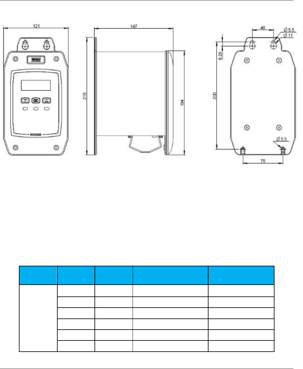
1.3 Specifications
TECHNICAL
Maximum accuracy error: + / - 1 % measurement
Angle measurement: Resolution → 0,00°
Results memory capacity: 20.000 (minimum)
Pset memory capacity: 10 (one Pset = one MWR-TA)
Maximum number of identifier strings: 3 strings (33 characters total)
Units of Measurement supported: Nm, ft-lbs, in-lbs, ozf ft, ozf in, kgf cm, kgf m
Average radio range: 10m
POWER SUPPLY
Input power: 100-240 VAC with 50/60 Hz
AC Power Consumption: 25 W (maximum)
Focus 60 / Focus 61 User Guide Introduction
9839 0211 01 Edition 1.1 9 (106)
DIMENSIONS
The unit of the dimensions is in mm.
INTERFACES
Ethernet ports
Barcode Scanner interface (RS232)
I / O BUS (CAN)
Wave Flexible Antenna connector
Radio module frequencies:
Country
Number
Channel
Frequency [MHz]
Data rate [bit/s]
Europe
1
51
868.034
38400
2
56
868.297
38400
3
60
868.502
38400
4
64
868.706
38400
5
69
869.006
38400
6
76
869.273
38400

Introduction Focus 60 / Focus 61 User Guide
10 (106) 9839 0211 01 Edition 1.1
Country
Number
Channel
Frequency [MHz]
Data rate [bit/s]
7
82
869.573
38400
8
84
869.840
38400
9
51
868.034
19200
10
56
868.297
19200
11
60
868.502
19200
12
64
868.706
19200
13
69
869.006
19200
14
76
869.273
19200
15
82
869.573
19200
16
84
869.840
19200
USA
1
2
902.791
38400
2
9
906.478
38400
3
10
907.004
38400
4
17
910.691
38400
5
20
912.271
38400
6
31
918.064
38400
7
32
918.590
38400
8
46
925.963
38400
9
2
902.791
19200
10
9
906.478
19200
11
10
907.004
19200
12
17
910.691
19200
13
20
912.271
19200
14
31
918.064
19200
15
32
918.590
19200
16
46
925.963
19200

Focus 60 / Focus 61 User Guide Introduction
9839 0211 01 Edition 1.1 11 (106)
ENVIRONMENTAL CONDITIONS
Comply with the following environmental conditions during the operations:
Indoor Use ONLY
Environmental Class: II
IP Index according to EN IEC 60529: IP21
Room Temperature: 5 °C to 40 °C (41 °F to 104 °F)
Maximum relative humidity 80% for temperature up to 31 °C (88 °F) decreasing linearly to 50%
relative humidity at 40 °C (104 °F)
Altitude: Up to 2000m
SYSTEM REQUIREMENTS
Hereunder are the PC minimum requirements for installation of Focus 60 / Focus 61 Management
Software (ToolsTalk BLM):
Processor: 400 MHz (800 MHz or above recommended)
Memory: 256 Mb or above
Hard disk space: 610 Mb (1 Gb recommended)
Display: 1024 x 768, High Color (16-bit)
Operating Systems: Windows XP Service Pack 3 (SP3), Windows 7, Windows 8.1, Windows 10
Internet Explorer 5.01 or later (required for installation of the .NET Framework)
Windows Installer 3.1
Microsoft Excel 2007 or later (required to view the exported file with the tightening results)
NOTE: A system should meet these or the minimum requirements for the operating system,
whichever is higher.

Introduction Focus 60 / Focus 61 User Guide
12 (106) 9839 0211 01 Edition 1.1
1.4 EC Declaration of Conformity
The Focus 60 / Focus 61 is in conformity with the requirements of the council Directives on 06/22/1998
on the approximation of the laws of the Member States relating:
2014/30/EC
EMC Directive – Electromagnetic Compatibility
2011/65/EC
ROHS Directive – Risk of Hazardous Substances
1999/05/EC
R&TTE Directive – Radio and Telecommunications Terminal Equipment
2014/35/EC
LVD – Low Voltage Directive
The Focus 60 / Focus 61 complies with the following harmonized standards:
Emission
ETSI EN 301 489-3 v1.6.1
Electromagnetic compatibility and Radio spectrum Matters (ERM);
Electromagnetic Compatibility (EMC) standard for radio equipment
and services; Part 3: Specific conditions for Short-Range Devices
(SRD) operating on frequencies between 9 kHz and 246 GHz
EN 61000-3-2:2006 +
A1:2009 + A2:2009
Harmonic current emissions
EN 61000-3-3:2008
Voltage changes, voltage fluctuations and flicker
Immunity
ETSI EN 301 489-3 v1.6.1
Electromagnetic compatibility and Radio spectrum Matters (ERM);
Electromagnetic Compatibility (EMC) standard for radio equipment
and services; Part 3: Specific conditions for Short-Range Devices
(SRD) operating on frequencies between 9 kHz and 246 GHz
EN 61000-4-2:2009
Electrostatic discharge immunity test (ESD)
EN 61000-4-3:2006 +
A1:2008 + A2:2010
Radiated, radio-frequency, electromagnetic field immunity test
EN 61000-4-4:2004 +
A1:2010
Electrical fast transient / burst immunity test (BURST)
EN 61000-4-5:2006
Surge immunity test (Surge)
EN 61000-4-6:2009
Immunity to conducted disturbances, induced by radio-frequencies fields
EN 61000-4-11:2004
Voltage dips, short interruptions and voltage variations immunity test

Focus 60 / Focus 61 User Guide Introduction
9839 0211 01 Edition 1.1 13 (106)
NOTE: Connect the SIP/SOP of the Focus 60 / Focus 61 ONLY with devices in compliance
with the following harmonized standards:
IEC EN 60950-1:2005 + A1:2009
+ A2:2013
Safety of electronic equipment within the field of
audio/video, information technology and
communication technology. General requirements.
IEC EN 61010-1:2010
Safety requirements for electrical equipment for
measurement, control, and laboratory use. General
requirements.
NOTE: The internal battery of the Focus 60 / Focus 61 is in conformity with the following
harmonized standard:
IEC 60086-1:2015
Primary batteries – Part 1: General.
1.5 FCC/ IC
Changes or modifications not expressly approved by the party responsible for compliance could void the
user’s authority to operate the equipment.
This device complies with Part 15 of the FCC Rules and with Industry Canada license-exempt RSS
standard(s).
Operation is subject to the following two conditions: (1) this device may not cause harmful interference,
and (2) this device must accept any interference received, including interference that may cause undesired
operation.
Le présent appareil est conforme aux CNR d'Industrie Canada applicables aux appareils radio exempts de
licence.
L'exploitation est autorisée aux deux conditions suivantes: (1) l'appareil ne doit pas produire de brouillage,
et (2) l'utilisateur de l'appareil doit accepter tout brouillage radioélectrique subi, même si le brouillage est
susceptible d'en compromettre le fonctionnement.
System Overview Focus 60 / Focus 61 User Guide
14 (106) 9839 0211 01 Edition 1.1
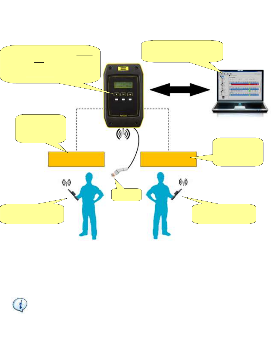
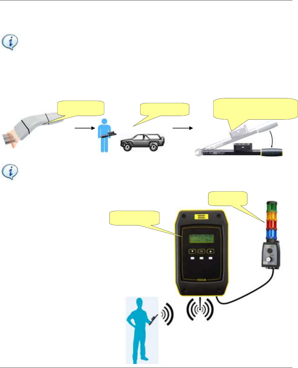
2 SYSTEM OVERVIEW
The Focus 60 / Focus 61 is a controller designed to manage a production line station where mechatronic
MWR wrenches are used to do tightening operations.
The Focus 61 can manage up to 10 MWR-TA divided into two stations. On each station, one MWR-TA
can be active at a time.
Focus 60 / Focus 61 User Guide System Overview
9839 0211 01 Edition 1.1 15 (106)
The Focus 60 can manage only one MWR-TA on one station:
Hereunder are the main functions of Focus 60 / Focus 61:
MAIN FUNCTIONS
FOCUS 60
FOCUS 61
MWR-TA management via 868 / 912 MHz radio module
X
X
Torque/Angle/Time monitoring (according to the MWR-TA model) to
control if the tightening is OK or Not OK
X
X
Barcode scanner interface
X
X
Job management for the MWR-TA on two stations
X
Programming Software (ToolsTalk BLM) to program the controller and
results download
X
X
Open Protocol connection
X
Toolsnet
X
X
Station 1
ToolsTalk BLM
Focus 60
MWR-TA
System Overview Focus 60 / Focus 61 User Guide
16 (106) 9839 0211 01 Edition 1.1
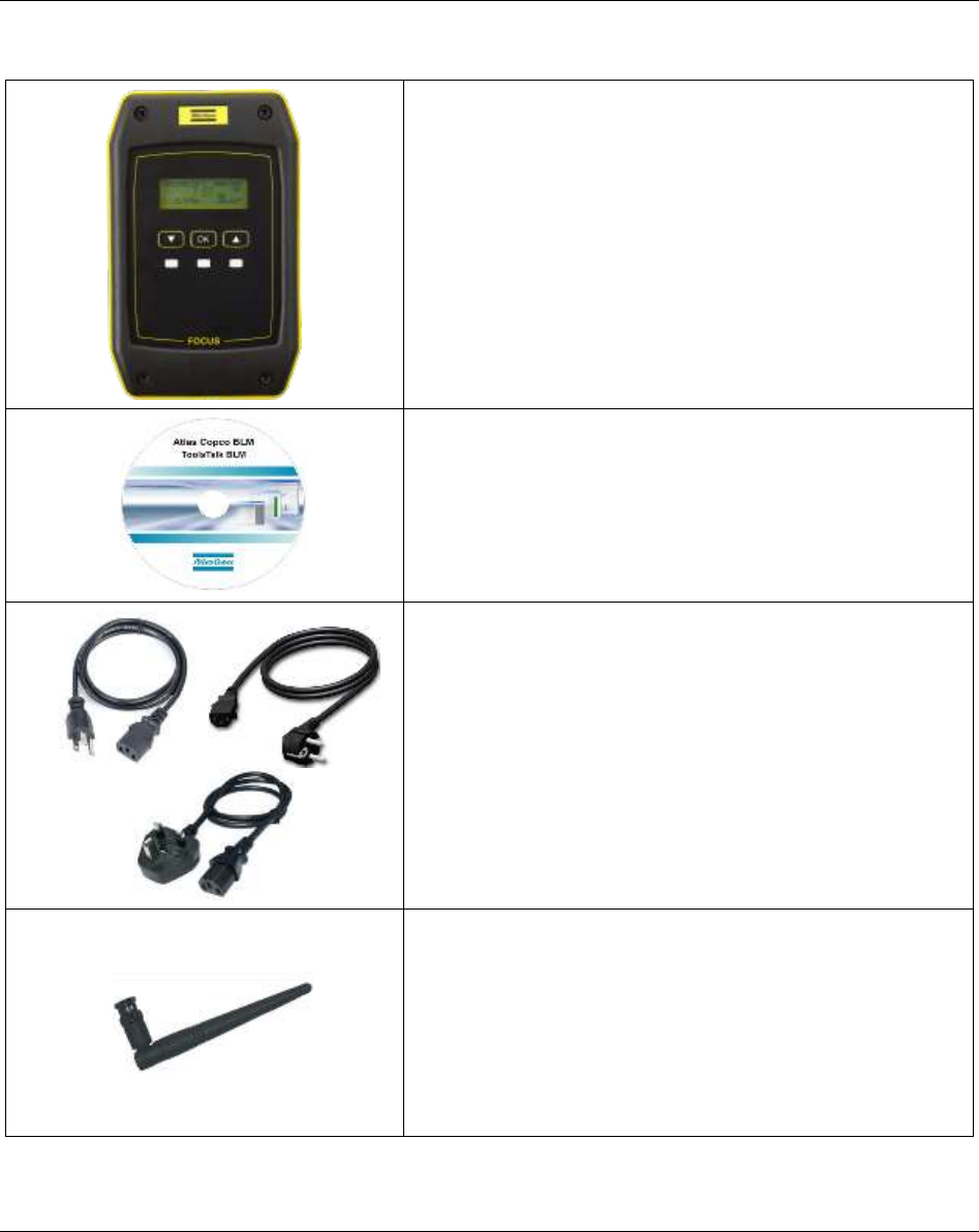
The Focus 60 / Focus 61 package contains the following items:
Focus 60 / Focus 61 Controller
(Focus 60 → P/N 8439 0044 30)
(Focus 61 → P/N 8439 0044 31)
The main module of the Focus 60 / Focus 61, which
contains all the Hardware and Firmware.
ToolsTalk BLM (P/N 8059 0981 10)
The Management Software. It represents the Pset and Job
programming, configuration and retrieving results.
Power Cables
The power cables depends on the region. The right one is
always in the package.
Antenna
(Antenna (868 MHz) → P/N 4027 5022 13)
(Antenna (915 MHz) → P/N 4027 5022 14)
The Antenna is installed on the Focus 60 / Focus 61, for
communicating with the MWR-TA.
Focus 60 / Focus 61 User Guide System Overview
9839 0211 01 Edition 1.1 17 (106)
The following additional module for Focus 60 / Focus 61 is available:
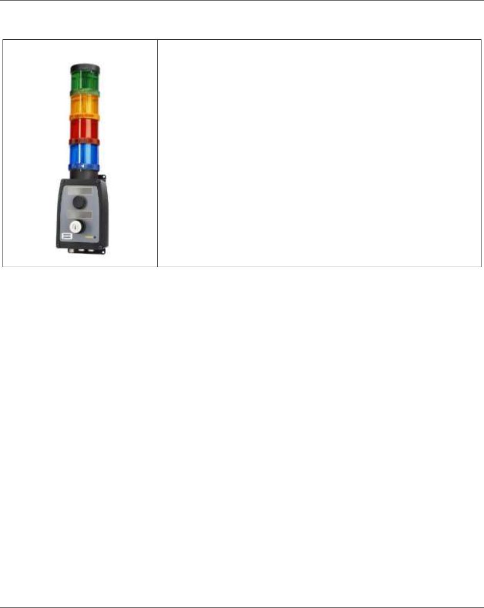
Stacklight (P/N 8433 0570 13)
Colored lamps for a real time indication of the tightening results,
system status etc.
Installation Instructions Focus 60 / Focus 61 User Guide
18 (106) 9839 0211 01 Edition 1.1
3 INSTALLATION INSTRUCTIONS
3.1 Installing Focus 60 / Focus 61
WARNING: Install the Focus 60 / Focus 61 close to the AC Power in order to manage it easy.
NOTE: Position the Focus 60 / Focus 61 so that the On-Off switch is easily accessible.
NOTE: For maximum tool performance, mount Focus 60 / Focus 61 in order to guarantee free
airflow. This improves the cooling of the controller.
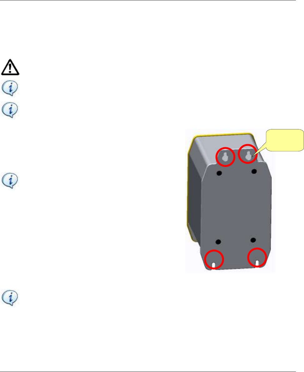
1. Mount the Focus 60 / Focus 61 either on the wall or on
steel plate by using four M5 screws. If mounting on a wall,
make sure to use the correct wall bracket (plug and screw).
If mounting on a steel plate, make sure that the plate is at
least 2 mm thick.
NOTE: Refer to the paragraph “Specifications –
Dimensions” to define how to install the M5 screws.
NOTE: Use ONLY the power cable provided with the Focus 60 / Focus 61 package. Using of
any other power cable may impair the protection provided by the equipment.
M5 screw
housing
Focus 60 / Focus 61 User Guide Installation Instructions
9839 0211 01 Edition 1.1 19 (106)
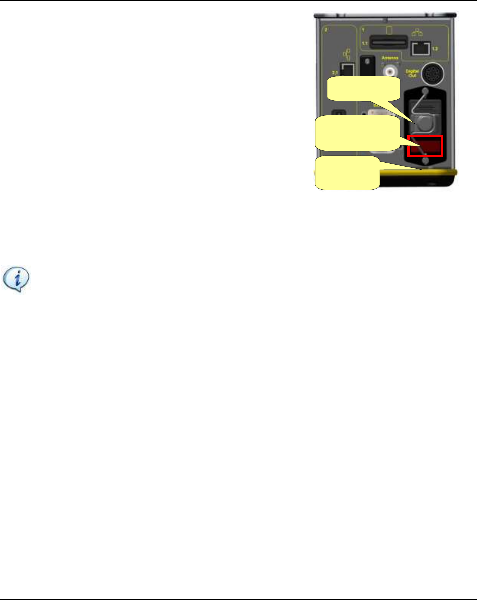
2. Connect the power cable from the multifunctional power socket
(refer to the figure on the right).
3. Connect the power cable to the AC Power.
NOTE: By using the On-Off switch (placed on the bottom side of the Focus 60 / Focus 61),
switch the Focus 60 / Focus 61 on, to verify that the installation is correct. Check that the light
of the On-Off switch is red and that the other LEDs (placed on the front panel) illuminate
correctly.
Fuses Holder
Multifunctional
power socket
On-Off
switch
User Interface Focus 60 / Focus 61 User Guide
20 (106) 9839 0211 01 Edition 1.1
4 USER INTERFACES
4.1 Focus 60 / Focus 61 Display
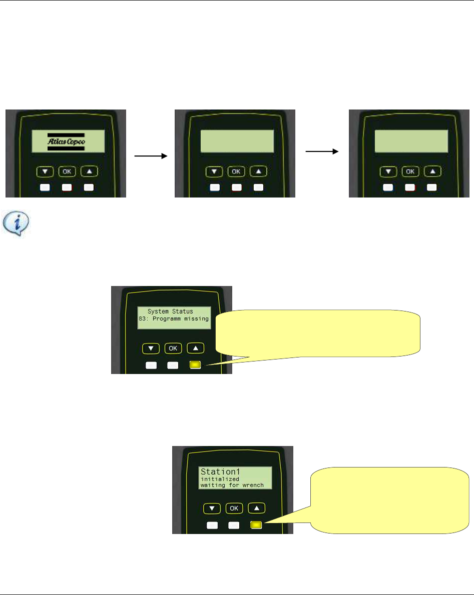
During the start-up of the Focus 60 / Focus 61, the following screens show in sequence:
NOTE: The above screens refer to the Focus 61 start-up. The start-up of the Focus 60 is the
same, unless the screen in the middle (“Focus 60” replaces “Focus 61”).
If no one MWR-TA is associated with any Station of the Focus 61, the following screen is shown:
If a MWR-TA is associated with one Station of the Focus 60 / Focus 61, but either the batteries level of
the MWR-TA is too low or the MWR-TA is out of the range of the Focus 60 / Focus 61, the following
screen is shown:
Focus 61
A67800031
INIT
Focus 60%
Protocol 0%
The Yellow LED points out
an ERROR (Refer to the
paragraph “LED” for further
details about LEDs)
The Yellow LED points out an
ERROR (Refer to the paragraph “LED”
for further details about LEDs)
Focus 60 / Focus 61 User Guide User Interfaces
9839 0211 01 Edition 1.1 21 (106)
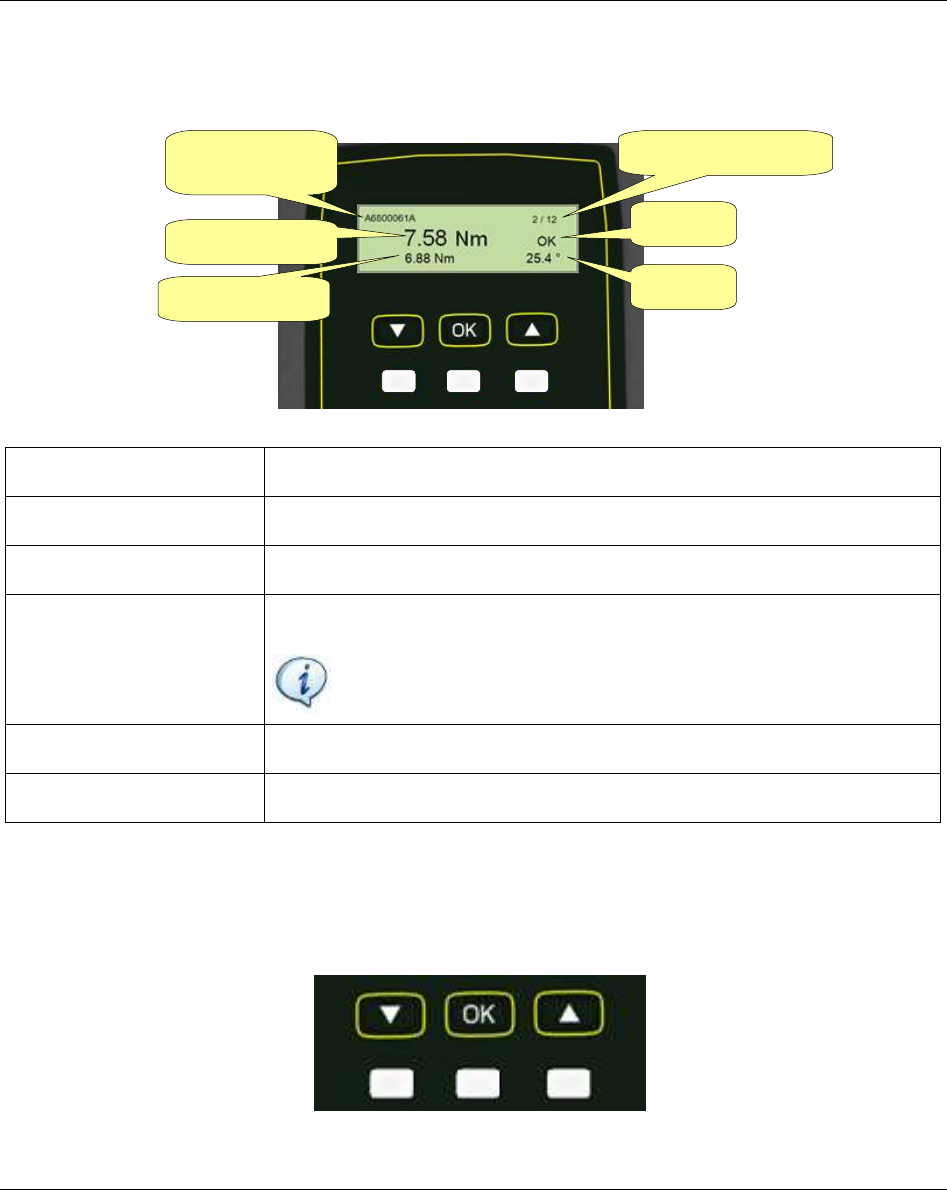
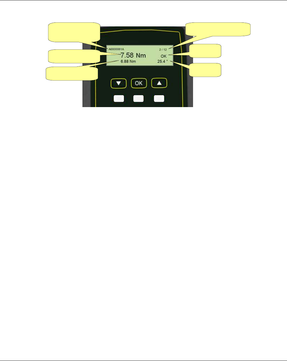
Associate the MWR-TA with a Station of the Focus 60 / Focus 61. After few seconds, the Focus 60 /
Focus 61 shows the data of the ongoing tightening operation on the MWR-TA (refer to the following
picture):
MWR-TA serial number
Serial number of the MWR-TA that is working.
Torque peak
Maximum torque measured during tightening phase.
Torque click
Click-point measured during tightening phase.
Status
Result of tightening operation of the operating MWR-TA.
NOTE: Refer to the paragraph “Executing tightening operations”
for further details.
Angle
Maximum angle measured during the tightening phase.
Batch counter
Number of the current tightening over the job step total tightenings.
4.2 Focus 60 / Focus 61 Keyboard
Use the keyboard to browse the Focus 60 / Focus 61menu and to change the info screens:
Torque peak
Torque click
Angle
Status
Batch counter
MWR-TA
serial number
User Interface Focus 60 / Focus 61 User Guide
22 (106) 9839 0211 01 Edition 1.1
4.3 Focus 60 / Focus 61 LEDs
There are three LEDs on the Focus 60 / Focus 61front panel:
Icon
Name
Description
OK
Middle button under the display.
It changes the settings of the device.
DOWN
Left button under the display.
It slides down the fields of the settings and
decreases value in settings menu.
UP
Right button under the display.
It slides up the fields of the settings and increases
value in settings menu.
LED color
Description
Blue
The Blue LED is on when the system is ready.
The system is not ready, if:
- there is an error (Main error flag in MainState
but field is set);
- the system is processing an update (any of the
flags in the update field of the MainState but
field is set);
- the “Ready” flag in the script station state for
any enabled station is not set.
Red/ Blinking
Green
Red: The Focus 60 / Focus 61communicates with
ToolsTalk BLM.
Blinking Green: The Focus 60 / Focus 61
communicates with a MWR-TA.
Yellow
The Focus 60 / Focus 61 display shows an error.
LEDs
Focus 60 / Focus 61 User Guide User Interfaces
9839 0211 01 Edition 1.1 23 (106)
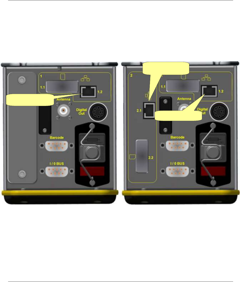
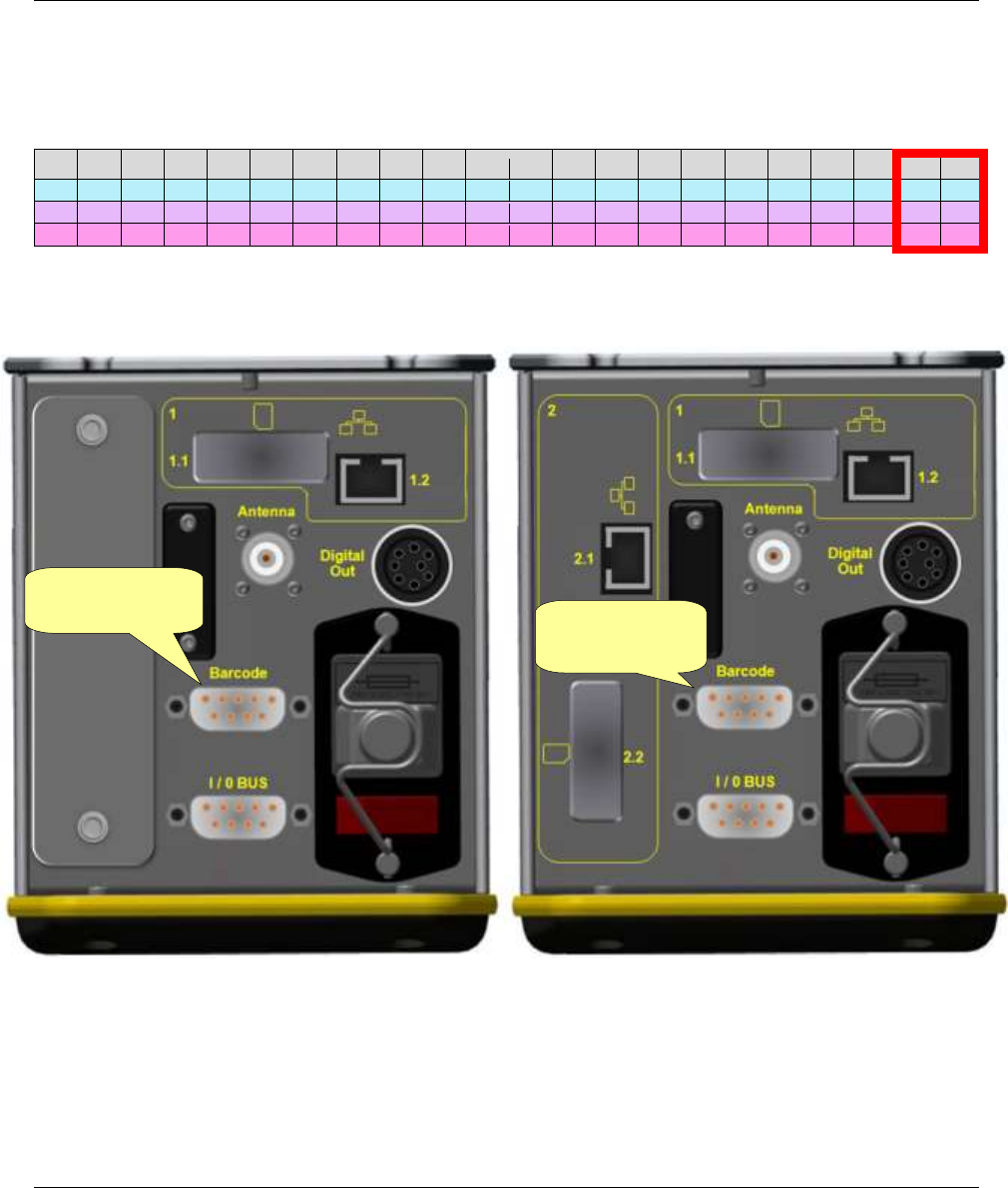
4.4 Focus 60 / Focus 61 Ethernet Ports
The Ethernet Port allows the communication between the Focus 60 / Focus 61 and ToolsTalk BLM.
Two Ethernet Ports characterize the Focus 61 (Focus 60 has only one). See the pictures below.
Ethernet Port 2.1
Ethernet Port 1.2
Ethernet Port 1.2
Focus 60
Focus 61
User Interface Focus 60 / Focus 61 User Guide
24 (106) 9839 0211 01 Edition 1.1
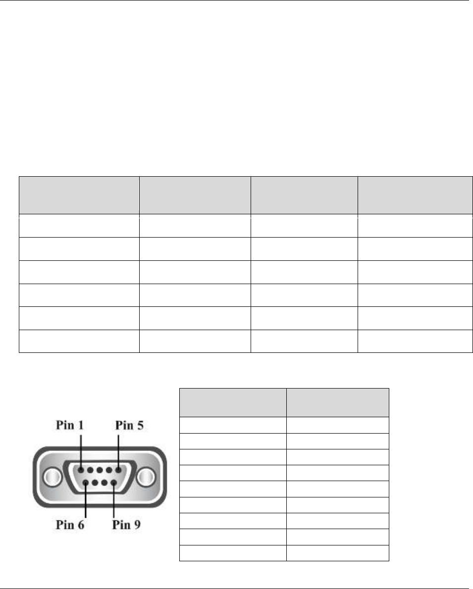
4.5 Focus 60 / Focus 61 Barcode scanner Interface (RS232)
The Focus 60 / Focus 61 has a barcode interface RS232 (see the pictures below) with a switchable 5V
power supply (max 400 mA).
The Barcode interface RS232 parameters are as follows:
8 data bit
1 stop bit
no parity
Data Rate: it is settable according to customer needs (refer to the following table). By default, the Data
Rate is set on 38400 bit/s.
Data rate nominal
(bit/s)
Data rate actual
(bit/s)
Mismatch
Note
9600
9615
0.2%
19200
19231
0.2%
38400
38462
0.2%
76800
76923
0.2%
115200
114286
0.7%
230400
235294
2.1%
Not yet available
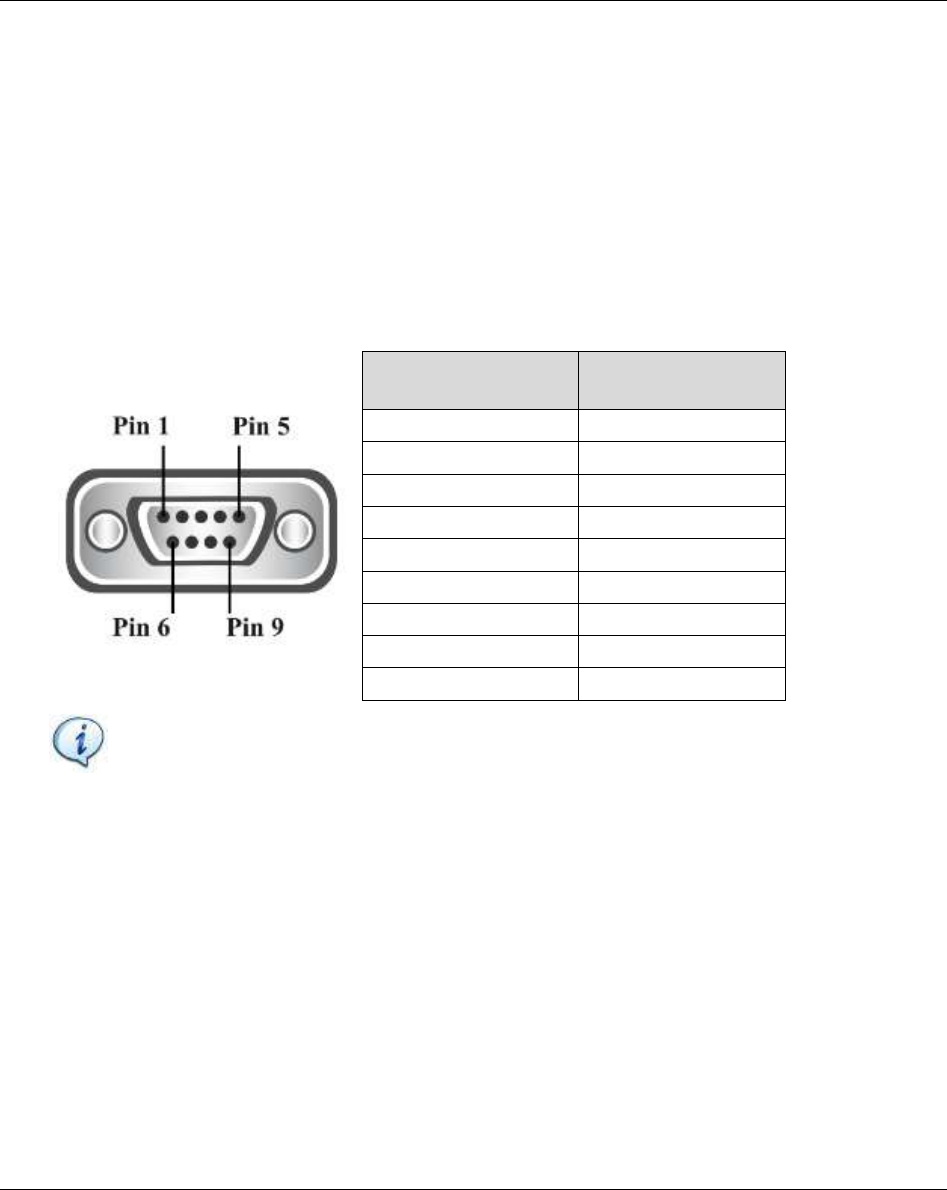
Pin assignment barcode scanner port:
PIN #
Signal
1
2
RX
3
TX
4
5
GND
6
7
8
9
+5 VDC
Focus 60 / Focus 61 User Guide User Interfaces
9839 0211 01 Edition 1.1 25 (106)
No Prefix
No Suffix
TERMINATOR: CR + LF
Terminator Specification:
1
2
3
4
5
6
7
8
9
10
11
12
13
14
15
16
17
18
19
20
21
22
V
E
H
I
C
L
E
_
I
D
E
N
T
_
N
U
M
B
E
R
\r
\n
56
45
48
49
43
4C
45
5F
49
44
45
4E
54
5F
4E
55
4D
42
45
52
0D
0A
086
069
072
073
067
076
069
095
073
068
069
078
084
095
078
085
077
066
069
082
013
010
Barcode
interface RS232
Barcode
interface RS232
Focus 60
Focus 61
User Interface Focus 60 / Focus 61 User Guide
26 (106) 9839 0211 01 Edition 1.1
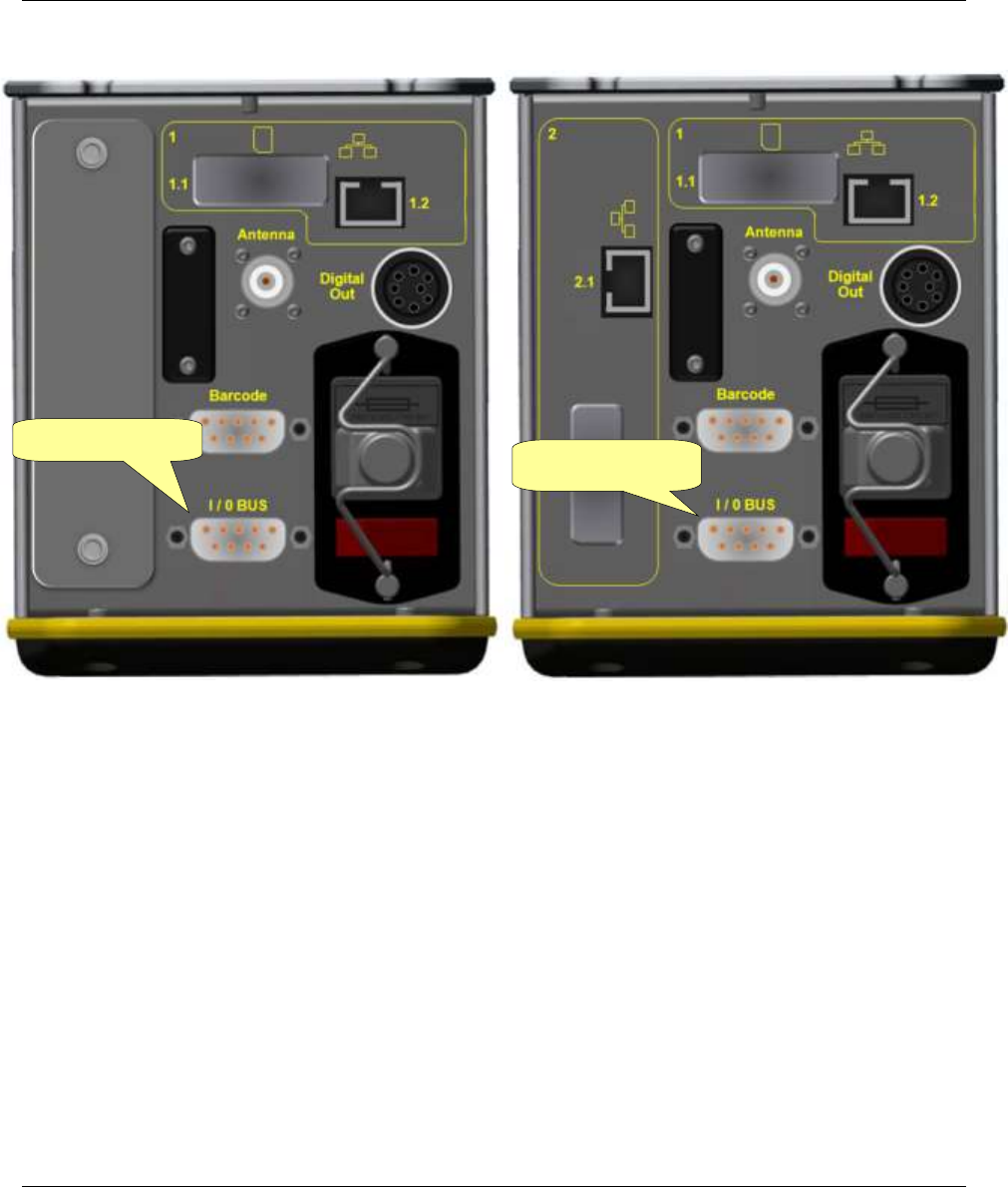
4.6 Focus 60 / Focus 61 I / O BUS (CAN)
I / O BUS (CAN) (see the pictures below) connects the Stacklight to the Focus 60 / Focus 61. The
Stacklight is an optional tool that supplies a real time indication of each tightening result, system status,
etc.
I / O BUS (CAN) parameters are as follows:
Data Rate: 250000 bit/s
Address range: 1…f
Current at 24V: 250mA (maximum)
Pin assignment I/O BUS (CAN):
PIN #
Signal
1
+24 VDC
2
Data Low
3
GND
4
GND
5
6
GND
7
Data High
8
9
+9 VDC
NOTE: All signals and voltages are galvanically separated from the device.
Focus 60 / Focus 61 User Guide User Interfaces
9839 0211 01 Edition 1.1 27 (106)
I/O BUS (CAN)
I/O BUS (CAN)
Focus 60
Focus 61
User Interface Focus 60 / Focus 61 User Guide
28 (106) 9839 0211 01 Edition 1.1
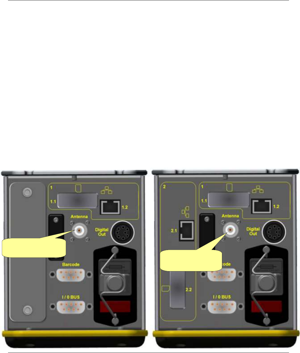
4.7 Focus 60 / Focus 61 Wave Flexible Antenna
The Wave Flexible Antenna (see the pictures below) allows the Focus 60 / Focus 61 to communicate with
the MWR-TA.
The Wave Flexible Antenna parameters are as follows:
1/4 Wavelength Whip Antenna
Rugged Flexible Plastic Finish
Available as BNC
Available as Straight or Right Angle
Omni-Directional Design
Impedance: 50 Ω
Operating Temperatures: – 30 °C to + 60 °C
Insulation resistance: 500 MΩ at 500 VDC
Wave Flexible
Antenna connector
Wave Flexible
Antenna connector
Focus 60
Focus 61
Focus 60 / Focus 61 User Guide Working with ToolsTalk BLM
9839 0211 01 Edition 1.1 29 (106)
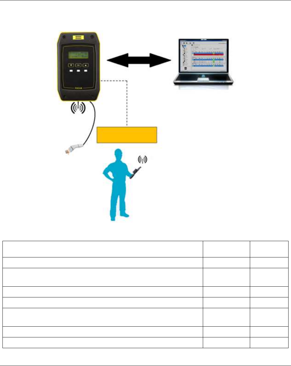
5 WORKING WITH ToolsTalk BLM
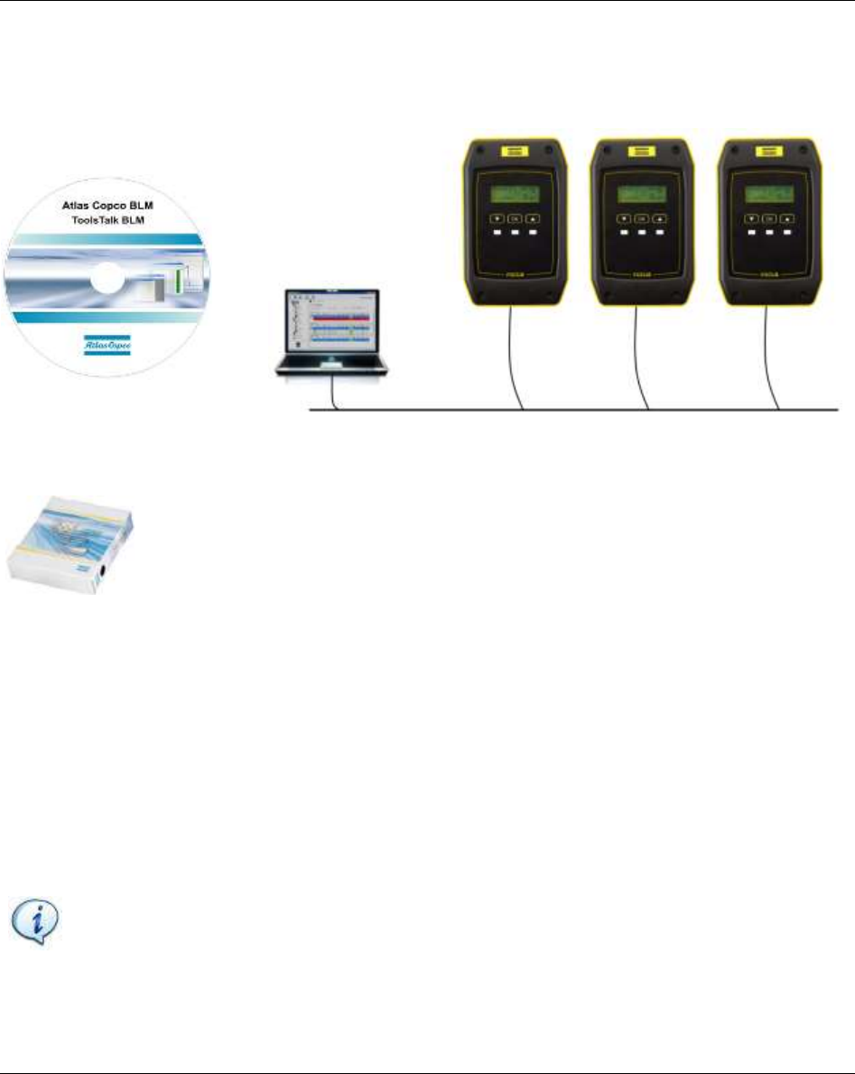
ToolsTalk BLM is a PC software package to manage the Focus 60 / Focus 61.
It offers user-friendly programming and real time monitoring.
ToolsTalk BLM is a configuration interface between the user and the Focus 60 / Focus
61.
The main features that characterize the configuration interface between the user and the Focus 60 / Focus
61 are as follows:
Stations configuration
Pset / Job definition
Events configuration (triggers to start a Job)
Focus 61 settings
Open Protocol settings
NOTE: For further details about Software Installation and Software Registration, refer
respectively to the paragraphs “Software Installation” and “Software Registration”.
ToolsTalk BLM
Focus 61
Working with ToolsTalk BLM Focus 60 / Focus 61 User Guide
30 (106) 9839 0211 01 Edition 1.1
5.1 Software Installation
NOTICE Install ToolsTalkBLM with PC administrator rights.
NOTICE Do not install the software from a shared folder/drive. Install the software from the
supplied CD; if the CD content is copied into a PC folder, it must be a PC local folder.
To install the software, double-click the setup file and do the following instructions.
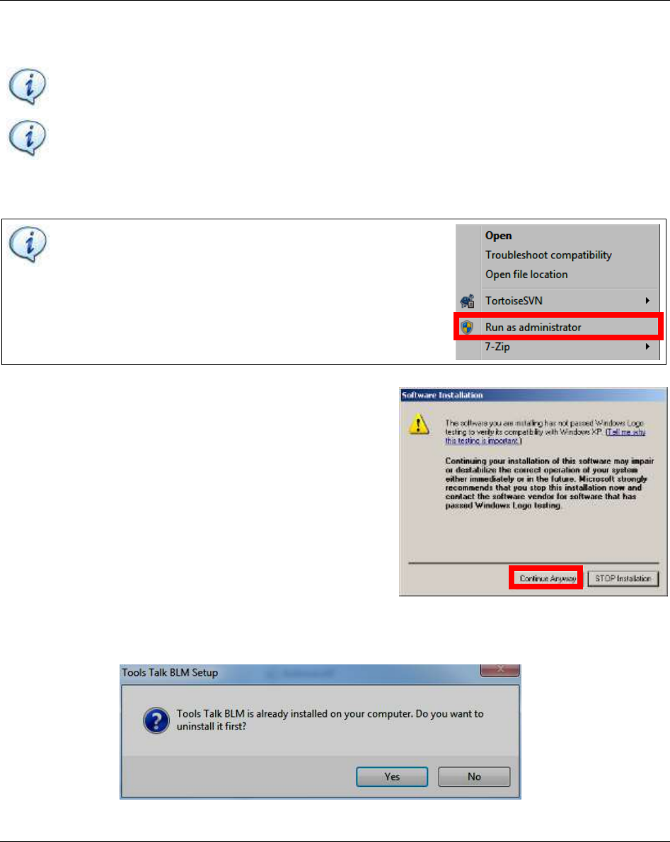
NOTICE For Window 7 operating system (or later), right-
click the setup file and select the Run as Administrator (see
the figure on the right):
Click Continue Anyway if the following Windows message
is shown:
After double-clicking the setup file, if ToolsTalk BLM is already installed on the computer, the following
message is shown:
Focus 60 / Focus 61 User Guide Working with ToolsTalk BLM
9839 0211 01 Edition 1.1 31 (106)
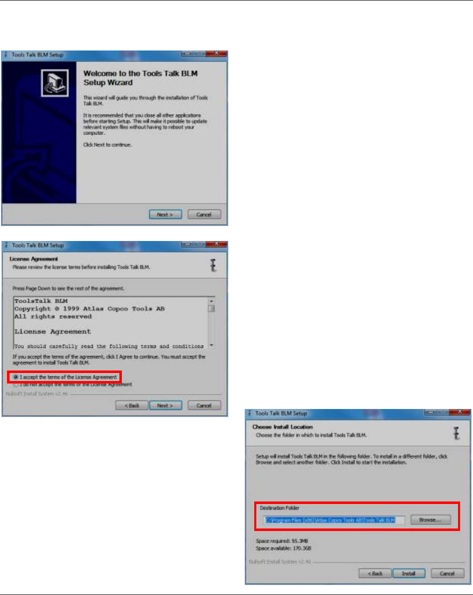
Click Yes in order to uninstall the ToolsTalk BLM software version installed on the computer. After
clicking Yes, it is possible to continue with the installation process:
Click Next to continue the installation process.
After carefully reading the License Agreement,
select the option “I accept the terms of the License
Agreement” and click Next.
Select the Destination folder in which to install the
ToolsTalk BLM. Finally click Install to start the
installation.
Working with ToolsTalk BLM Focus 60 / Focus 61 User Guide
32 (106) 9839 0211 01 Edition 1.1
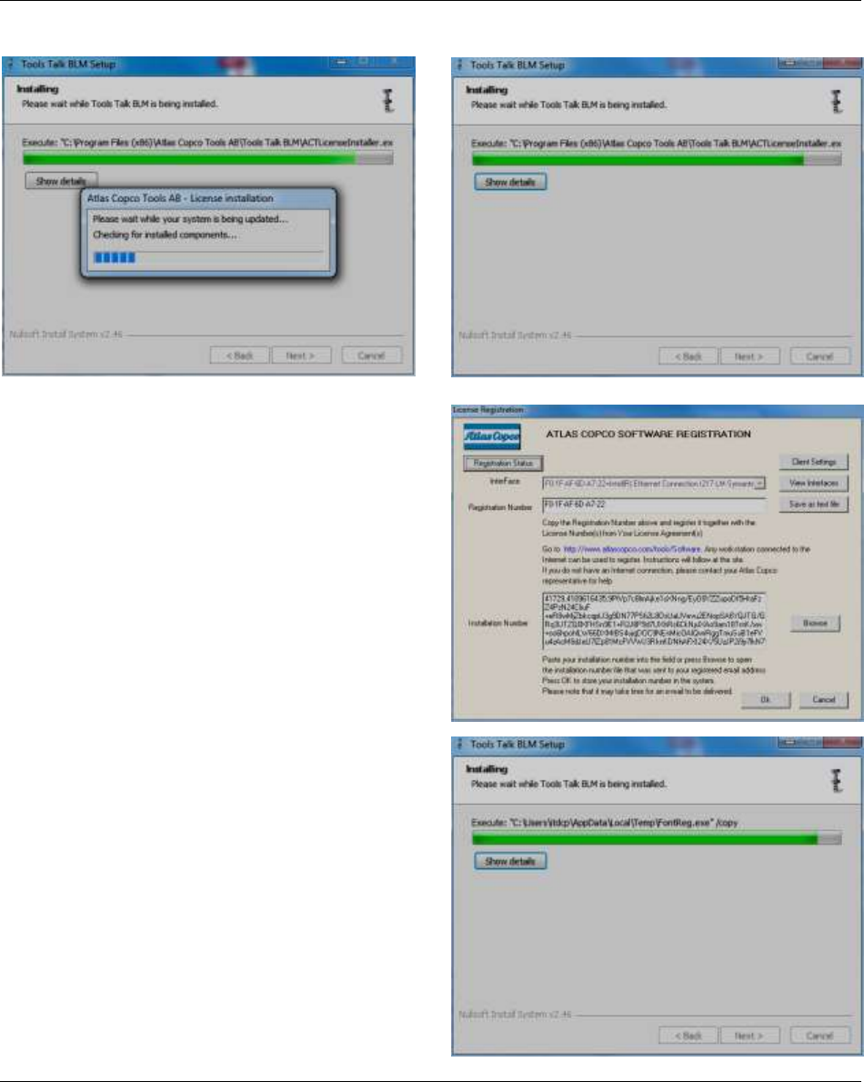
The following Installation screen alerts the operator that ToolsTalk BLM is being installed:
Before to finish the installation process, the screen on
the right shows:
After clicking Ok, the following Installation screen is
shown:
Focus 60 / Focus 61 User Guide Working with ToolsTalk BLM
9839 0211 01 Edition 1.1 33 (106)
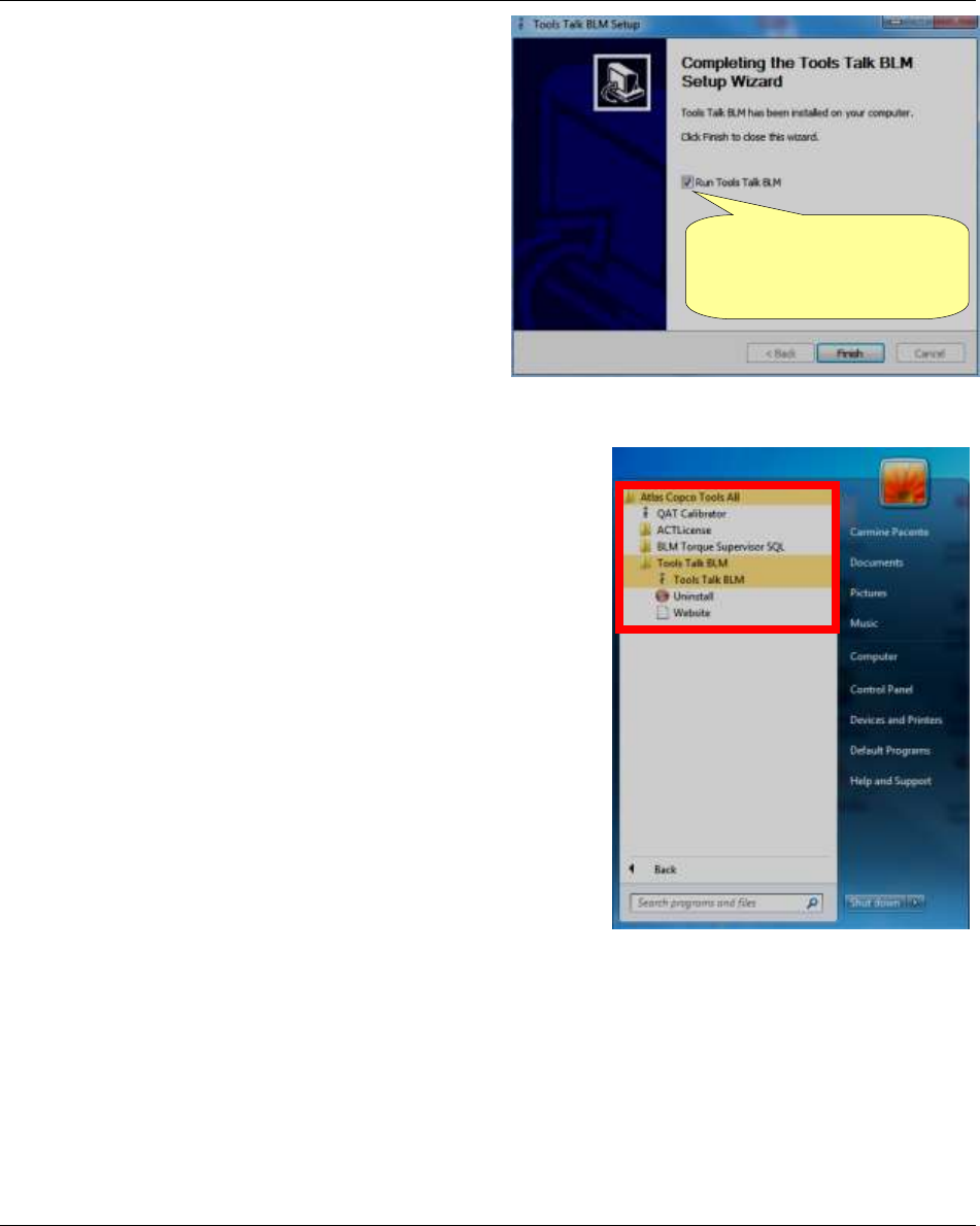
At the end of the installation process, the screen on
the right is shown:
Click Finish; ToolsTalk BLM is automatically started.
After installing the software, run the program by selecting Start
→ All Programs → Atlas Copco Tools AB → Tools Talk BLM:
By default, the “Run
ToolsTalk BLM” option
is flagged
Working with ToolsTalk BLM Focus 60 / Focus 61 User Guide
34 (106) 9839 0211 01 Edition 1.1
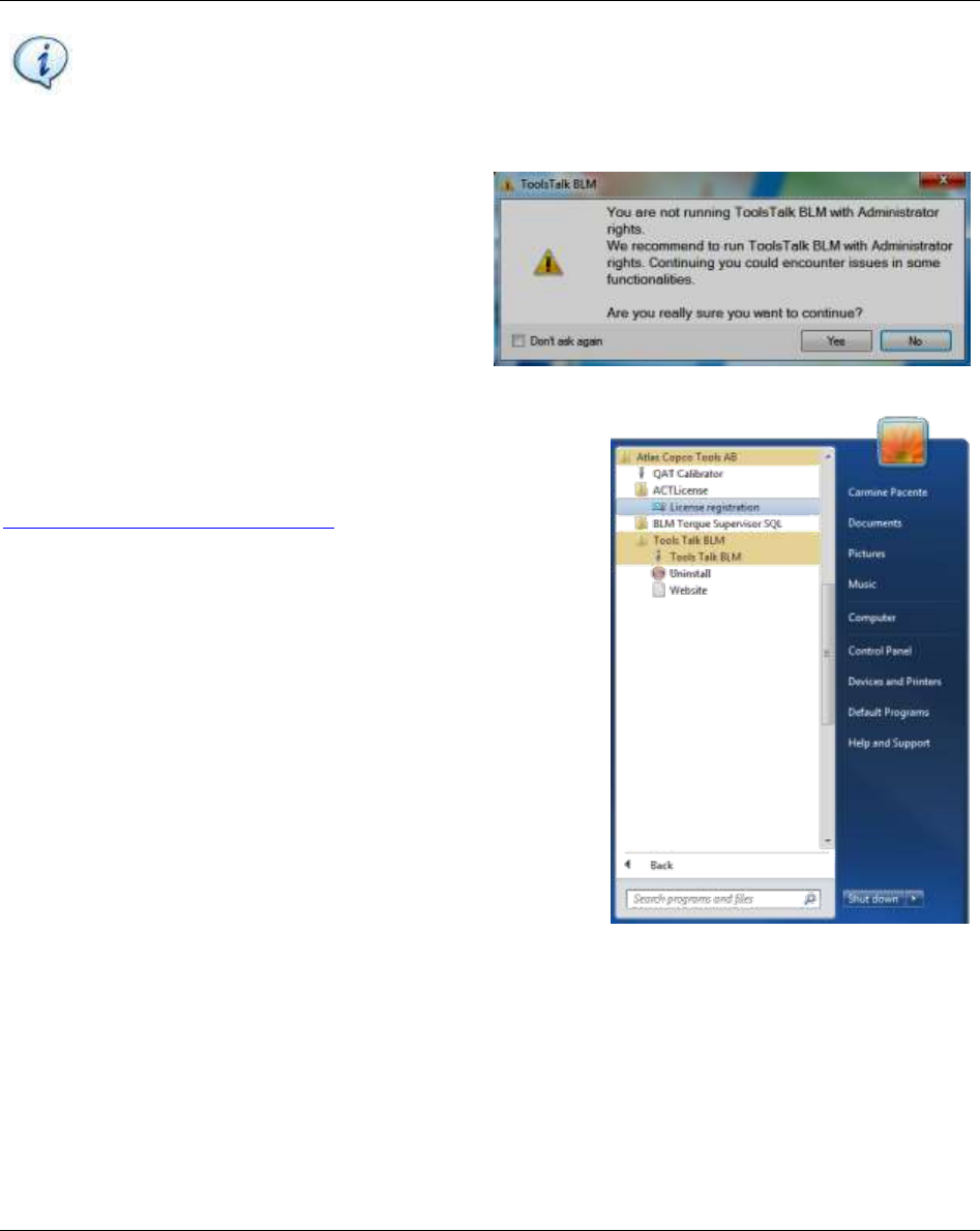
NOTICE ToolsTalk BLM Software runs also with Windows Standard User, except for the
following issue:
Log management
To avoid the previous issue, run ToolsTalk BLM as Administrator.
If the user does not run ToolsTalk BLM
with Administrator rights, the pop-up on
the right shows:
Click Yes to continue as Standard User: in
this case, the user could encounter issues
in some functionalities.
5.2 Software registration
After installing the software, register at
www.atlascopco.com/tools/software; if there is no registration,
the software works as demo for 60 days.
Once the software is installed, enter the registration form by
selecting Start → All Programs → Atlas Copco Tools AB →
ACTLicense (refer to the screen on the right).
5.3 Software upgrade
If there is a software update of ToolsTalk BLM, simply install the new version; the previous one is
automatically uninstalled.
Close the previous version during the update process.
There is no impact through the update on the settings, tightening programs and results.
Focus 60 / Focus 61 User Guide Working with ToolsTalk BLM
9839 0211 01 Edition 1.1 35 (106)
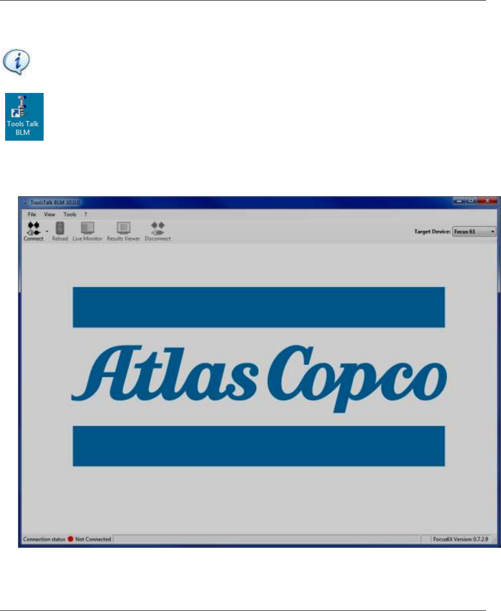
5.4 Connecting with the Focus 60 / Focus 61
NOTE: This paragraph describes the connection between Focus 61 and ToolsTalk BLM. The
procedure to connect Focus 60 with ToolsTalk BLM is basically the same.
Click ToolsTalk BLM icon to launch the software.
After clicking ToolsTalk BLM icon, the following screen shows:
Working with ToolsTalk BLM Focus 60 / Focus 61 User Guide
36 (106) 9839 0211 01 Edition 1.1
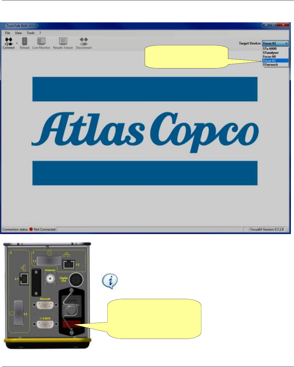
If necessary, select “Focus 60” or “Focus 61” in the Target Device area as shown in the screen below:
Turn the Focus 61 on and wait until the initialization is completed.
Then verify that the PC and Focus 61 are connected with the same
network.
NOTE: The connection between the ToolsTalk BLM and
the Focus 60 / Focus 61 is done via Ethernet.
Use the red button (placed
on the bottom of the
controller), to turn the
Focus 61 on
Select “Focus 61” in the
Target Device area
Focus 60 / Focus 61 User Guide Working with ToolsTalk BLM
9839 0211 01 Edition 1.1 37 (106)
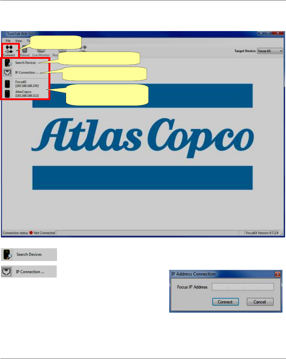
After turning the Focus 61 on, click Connect icon: Search Devices option, IP Connection… option and
the list of devices connected with the network show (see the screen below).
Search Devices option updates the list of devices connected with the network in
real time.
After clicking the IP Connection…
option, the IP Address Connection
pop-up (see the figure on the right)
shows. It connects a specific Focus
with the network.
Insert the IP Address of the desired
device and click Connect.
Search Devices option
Connect icon
IP Connection… option
List of devices connected
with the network
Working with ToolsTalk BLM Focus 60 / Focus 61 User Guide
38 (106) 9839 0211 01 Edition 1.1
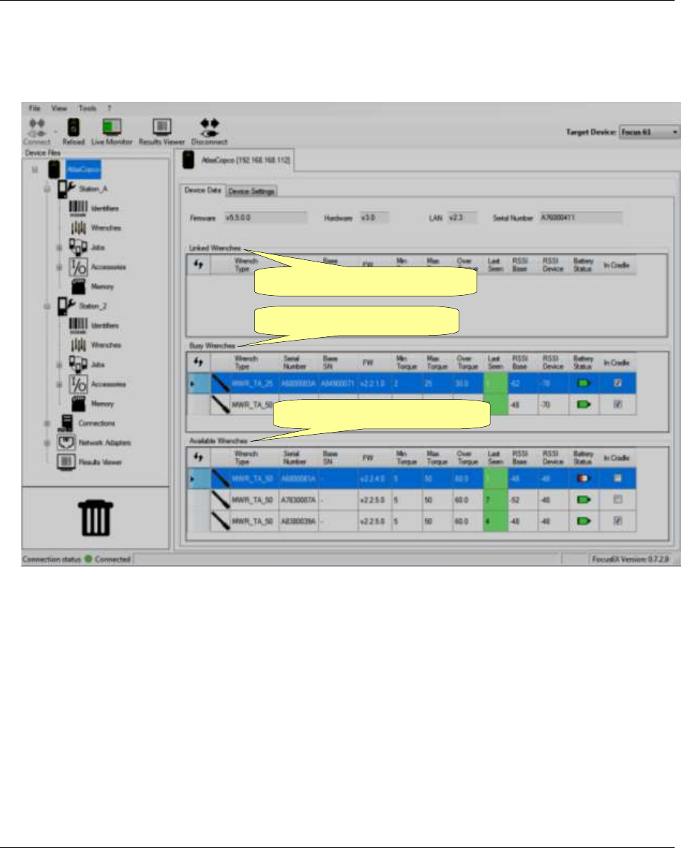
Select the desired device. Then wait until ToolsTalk BLM interface shows:
After connecting the desired device, Connect icon (placed on the toolbar) gets disabled, while Disconnect
icon gets active: click to disconnect the system:
Device
Files
area
Linked Wrenches
Device Data and
Device Settings
Toolbar
Menu list
Busy Wrenches
Available Wrenches
Status bar
Target Device area
Disconnect
icon
Focus 60 / Focus 61 User Guide Working with ToolsTalk BLM
9839 0211 01 Edition 1.1 39 (106)
5.4.1 Menu list
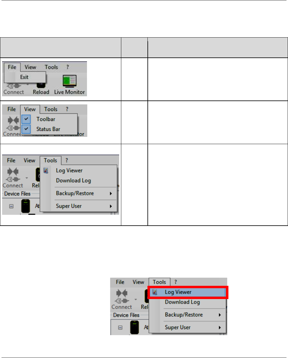
The following options are available on the ToolsTalk BLM Menu list:
ILLUSTRATION
NAME
DESCRIPTION
File
“File” allows customer to exit from ToolsTalk
BLM Software.
View
“View” enables or disables the Toolbar and the
Status Bar.
Tools
“Tools” provides the following functions:
- Log Viewer (refer to paragraph “Enabling LOG
Viewer”)
- Download Log (refer to the paragraph
“Download LOG”)
- Backup/Restore (refer to paragraph “ToolsTalk
BLM Backup and Restore / Update”)
- Super User (available only for Atlas Copco
Service Personnel)
5.4.1.1 Enabling LOG Viewer
Enable LOG Viewer to trace the ToolsTalk BLM operations with the Focus 60 / Focus 61: this is helpful
for troubleshooting activities.
Select Tools → Log Viewer:
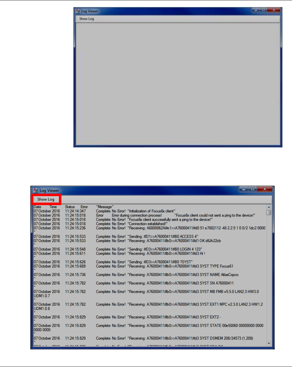
Working with ToolsTalk BLM Focus 60 / Focus 61 User Guide
40 (106) 9839 0211 01 Edition 1.1
The window on the right
shows:
Click Show Log to display the information related to the “Log Messages” (operations made between the
ToolsTalk BLM and the Focus 60 / Focus 61):
Focus 60 / Focus 61 User Guide Working with ToolsTalk BLM
9839 0211 01 Edition 1.1 41 (106)
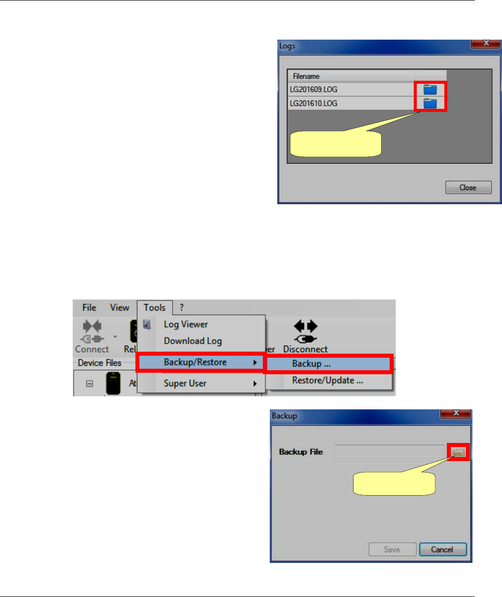
5.4.1.2 Download LOG
Select Tools → Download LOG to download the LOG file
stored in the Focus 60 / Focus 61 memory.
After clicking, the following pop-up shows:
Click the Folder icon to select the destination folder of the
LOG file.
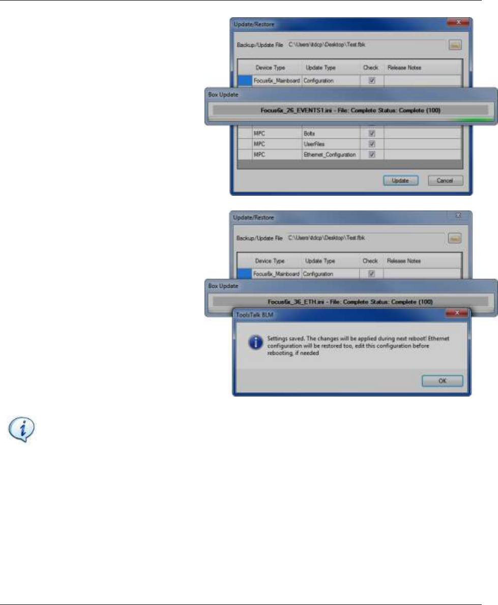
5.4.1.3 ToolsTalk BLM Backup and Restore / Update
5.4.1.3.1 Performing Backup
Select Tools → Backup/Restore → Backup… (see the figure below):
After clicking Backup…, the pop-up on the right shows:
Folder icon
Folder icon
Working with ToolsTalk BLM Focus 60 / Focus 61 User Guide
42 (106) 9839 0211 01 Edition 1.1
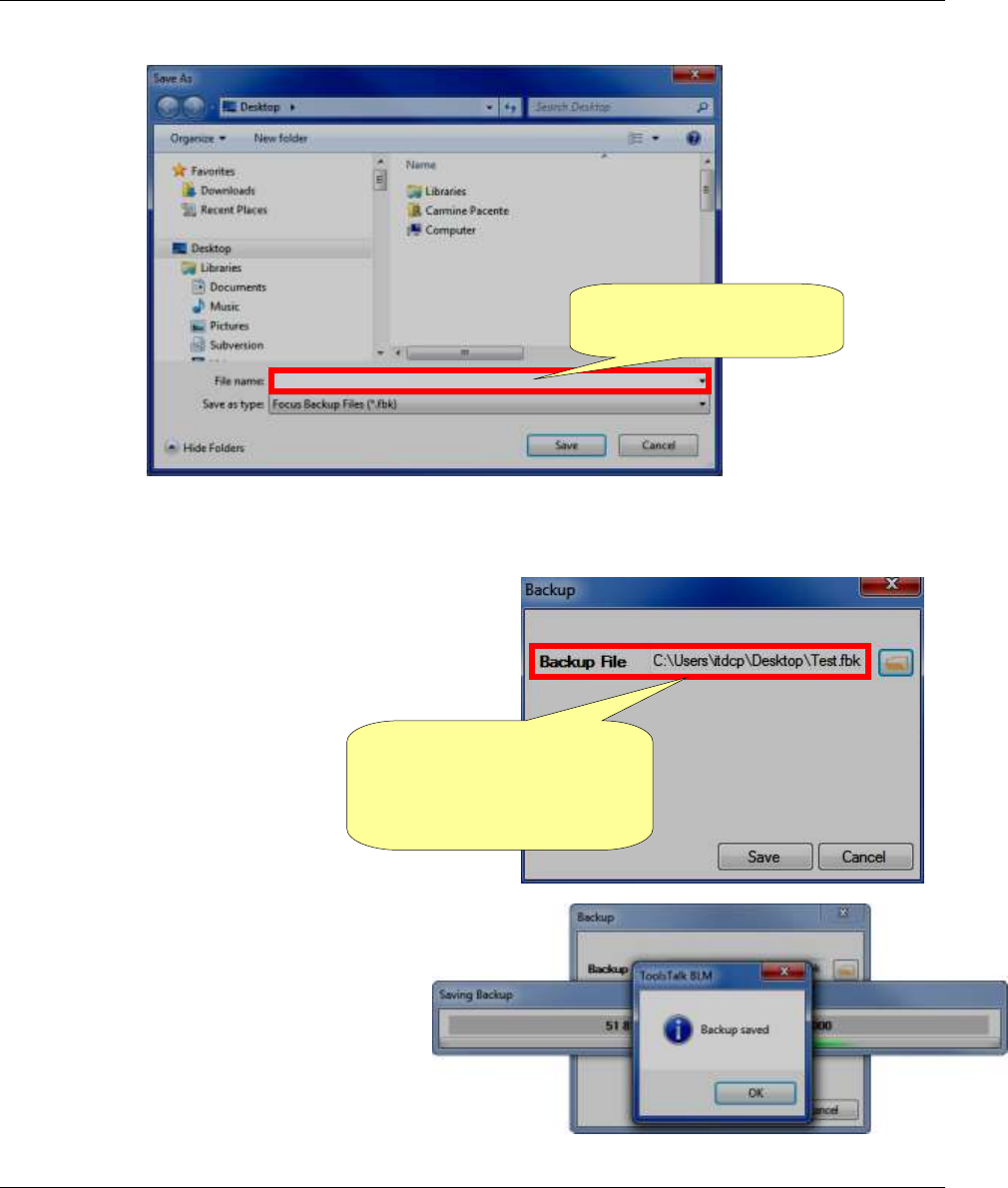
Click the “Folder” icon (see the above pop-up) to define the Backup File; the following window shows:
Type the Focus Backup File name into the related text box (see the figure above) and select the desired
“destination folder”.
Finally, click Save; the pop-up on
the right shows:
Make sure that the text box of the Backup File
shows the selected path that leads to the Focus
Backup File name; then click Save.
The “Saving Backup process” starts
automatically.
At the end of the “Saving Backup process” a
“Backup saved” pop-up shows (see the figure
on the right).
Click OK.
The text box of the Backup
File shows the selected path
that leads to the Focus
Backup File name
Text box of the Focus
Backup File name
Focus 60 / Focus 61 User Guide Working with ToolsTalk BLM
9839 0211 01 Edition 1.1 43 (106)
5.4.1.3.2 Performing Restore / Update
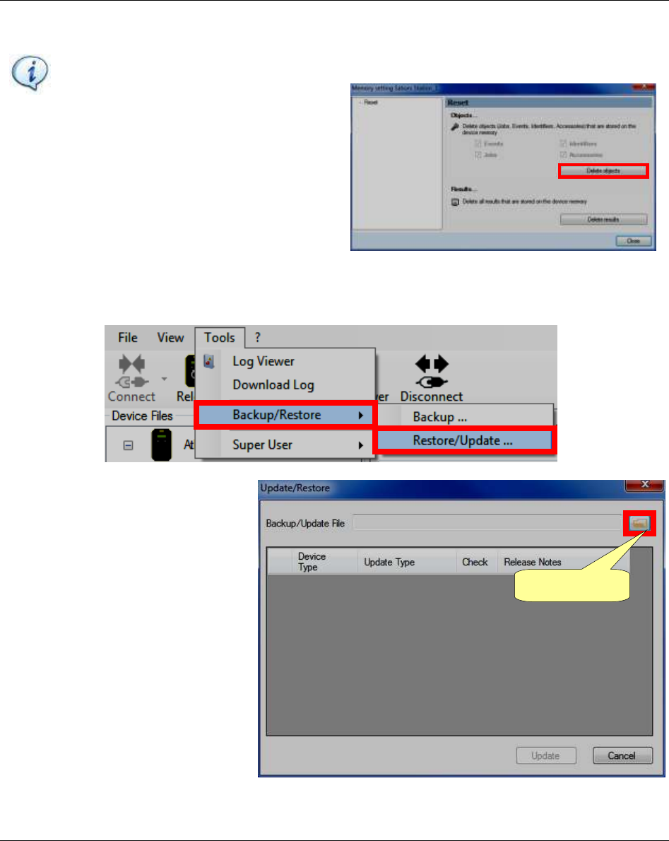
NOTE: Please, clean the system before restore backups.
For both Stations, click Memory (placed in
the Device Files area); the pop-up on the
right shows:
Click “Delete objects” to delete Jobs,
Events, identifiers, Accessories stored on
the device memory.
Finally, remove all of the wrenches.
Select Tools → Backup/Restore → Restore/Update… (see the figure below):
After clicking Restore/Update…, the
pop-up on the right shows:
Folder icon
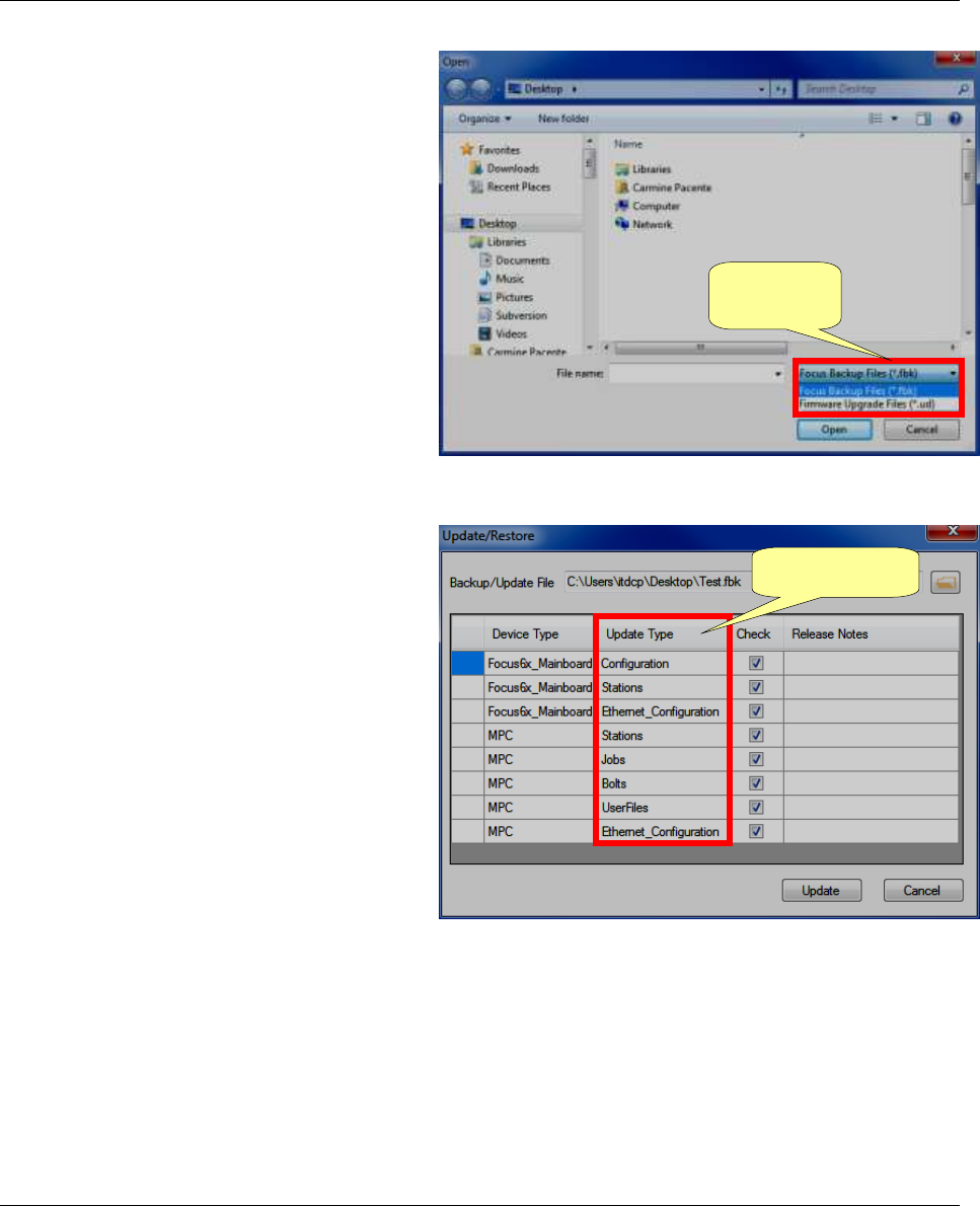
Working with ToolsTalk BLM Focus 60 / Focus 61 User Guide
44 (106) 9839 0211 01 Edition 1.1
Click the “Folder” icon (see the above pop-
up) to open either the Focus Backup File or
the Firmware Upgrade File; the window on
the right shows:
Select either the Focus Backup File or the
Firmware Upgrade File with the related
filename extension.
For the Focus Backup File open the drop
down list on the right of the “File name” text
box and select Focus Backup File (*.fbk).
For the Firmware Upgrade File (sent by
manufacturer to upgrade the Focus 60 / Focus
61) open the drop down list on the right of the
“File name” text box and select Firmware
Upgrade File (*.ud).
Finally, click Open; the pop-up on the right
shows:
Make sure that each Updated Type is correctly
checked; then click Update.
Filename
extension
Update Types
Focus 60 / Focus 61 User Guide Working with ToolsTalk BLM
9839 0211 01 Edition 1.1 45 (106)
The “Focus Update process” starts
automatically (see the figure on the right).
At the end of the “Focus Update process”
a “Settings saved” pop-up shows (see the
figure on the right).
Do the instructions provided into the
“Settings saved” pop-up and click OK.
NOTE: Before rebooting, it is highly recommended to select / confirm the correct Ethernet
configuration, by acting on the Network Adapters section placed in the Device Files area.
Working with ToolsTalk BLM Focus 60 / Focus 61 User Guide
46 (106) 9839 0211 01 Edition 1.1
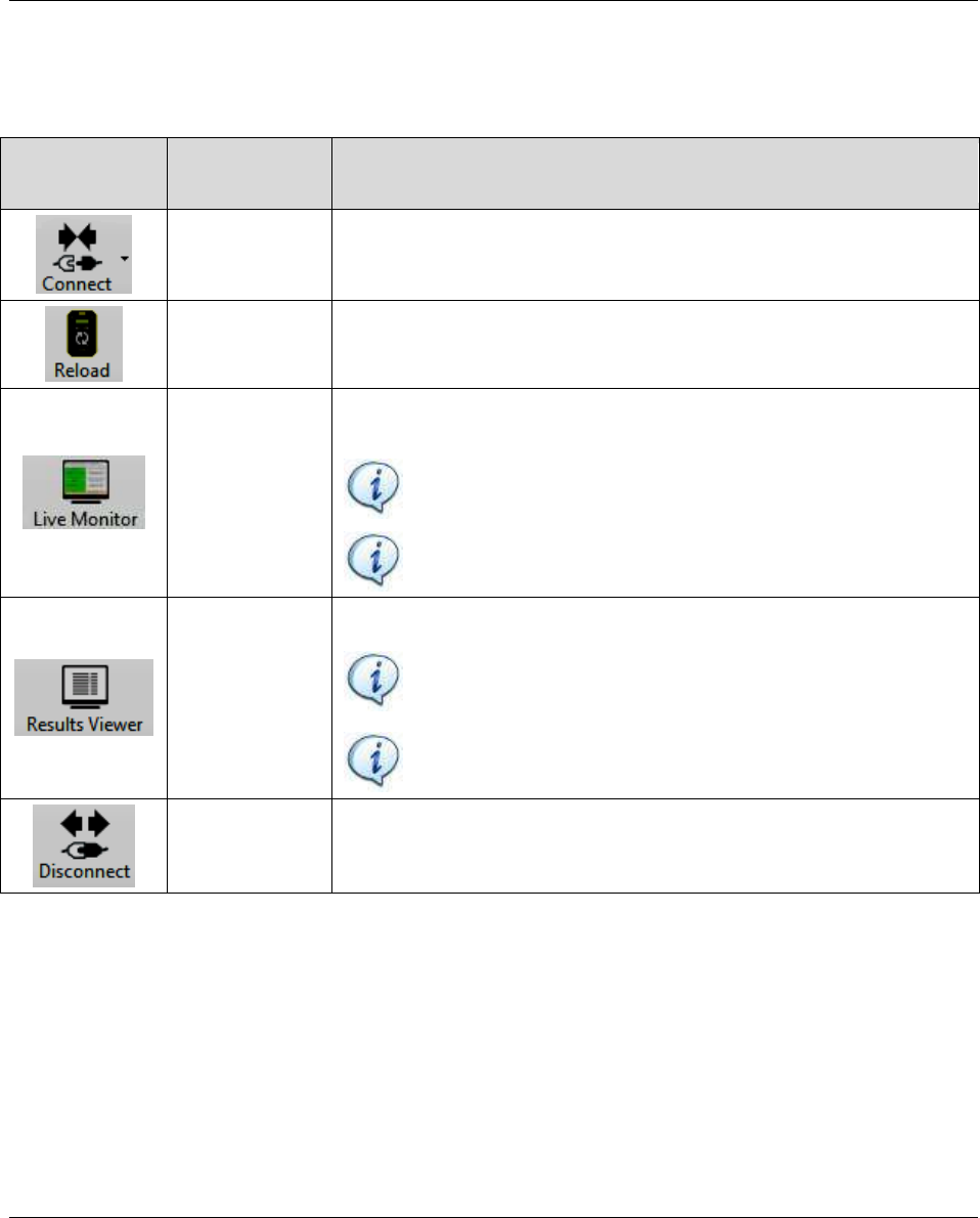
5.4.2 Toolbar
The Toolbar icons are shortcuts to the following functions:
ICON
ICON NAME
DESCRIPTION
Connect
“Connect” icon connects the ToolsTalk BLM with the Focus 60 /
Focus 61.
Reload
“Reload” icon reloads the data of the Focus 60 / Focus 61
connected.
Live Monitor
“Live Monitor” icon opens the Live Monitor functions, showing in
real time the tightening from the connected wrenches.
NOTE: The tightenings (in real time) are displayed only
one by one.
NOTE: Refer to the paragraph “Live Monitor” for further
details.
Results
Viewer
“Results Viewer” icon shows the latest results stored by the device.
NOTE: The only applicable filters are those set on the
device (refer to the paragraph “Device Settings” for further
details).
NOTE: Refer to the paragraph “Results Viewer” for further
details.
Disconnect
“Disconnect” icon disconnects the ToolsTalk BLM from the Focus
60 / Focus 61.
Focus 60 / Focus 61 User Guide Working with ToolsTalk BLM
9839 0211 01 Edition 1.1 47 (106)
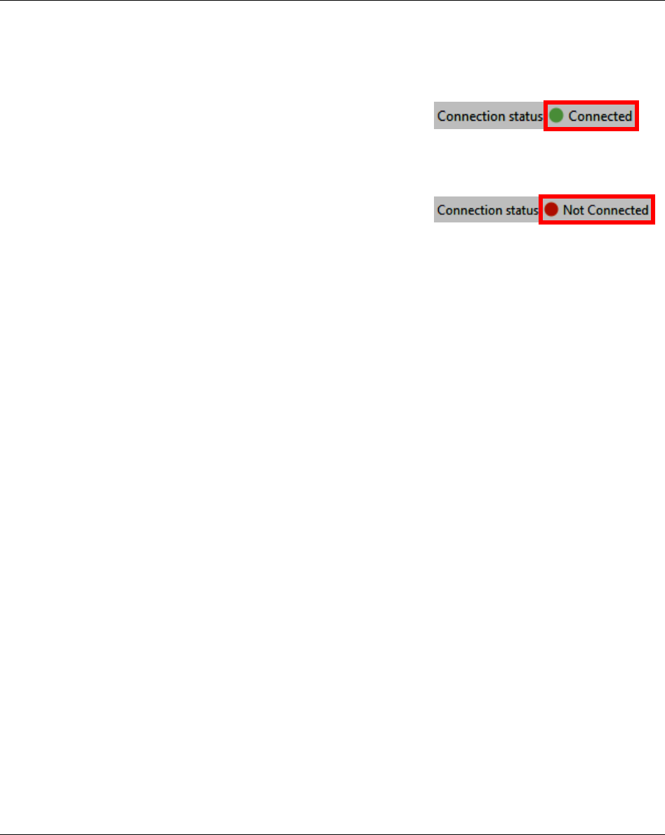
5.4.3 Status bar
The status bar shows the connection status between Focus 60 / Focus 61 and ToolsTalk BLM.
When the connection between Focus 60 / Focus 61 and ToolsTalk
BLM is stable, a green bullet followed by “Connected” represents
the connection status (see the figure on the right):
If the connection between Focus 60 / Focus 61 and ToolsTalk
BLM is not found, a red bullet followed by “Not Connected”
represents the connection status (see the figure on the right):
Programming Focus 60 / Focus 61 Focus 60 / Focus 61 User Guide
48 (106) 9839 0211 01 Edition 1.1
6 PROGRAMMING Focus 60 / Focus 61
The Focus 61 can manage one or two stations, while the Focus 60 can manage only one station.
The stations are virtual, used by the software to let the device manage the jobs of the operators working,
for instance, of the two sides of the same assembly area (in the case of the Focus 61).
For each station, the sequence of operations that the operator must execute is defined into one or more
Jobs. Each Job is a set of Pset, which is the tightening program loaded on the MWR-TA.
NOTE: The Focus 60 can ONLY handle one Job and one Pset.
Programming of Stations,
Jobs, Psets and Events
Events
One MWR-TA for
each station
One or more
Jobs for each
station
The Focus 61 can manage one or
two stations.
The Focus 60 can manage
ONLY one station.
One or more
Jobs for each
station
One MWR-TA for
each station
Station 2
Station 1
ToolsTalk BLM
Focus 60 / Focus 61 User Guide Programming Focus 60 / Focus 61
9839 0211 01 Edition 1.1 49 (106)
The Jobs start either automatically when the Focus 60 / Focus 61 turns on or starting the operation by
external signal given by scanning a barcode string or by the AOP command (refer to paragraph “Events
Configuration”).
Connect ONLY one barcode scanner with the Focus 60 / Focus 61.
It is not possible to connect more stacklights (or other compatible components) with the Focus 60 / Focus
61, if the connected I/O Device forwards the I/O Bus physically.
Connect ToolsTalk BLM with the Focus 60 / Focus 61 (refer to paragraph “Connecting with the Focus 60
/ Focus 61”).
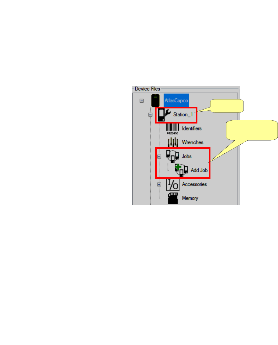
On the left of the main screen (in the Device
Files area), there are the Station(s) with the
associated Jobs:
The following paragraphs describe step-by-step how to configure Stations, Psets, Jobs and Events, and
how to associate the MRW Wrenches with Station(s).
Jobs associated
with Station_1
Station_1
Programming Focus 60 / Focus 61 Focus 60 / Focus 61 User Guide
50 (106) 9839 0211 01 Edition 1.1
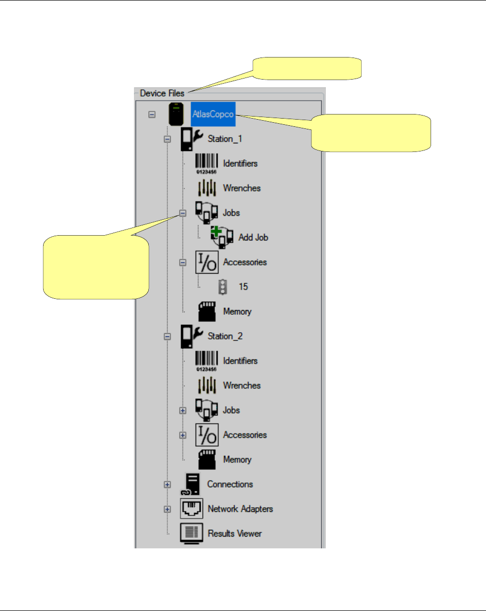
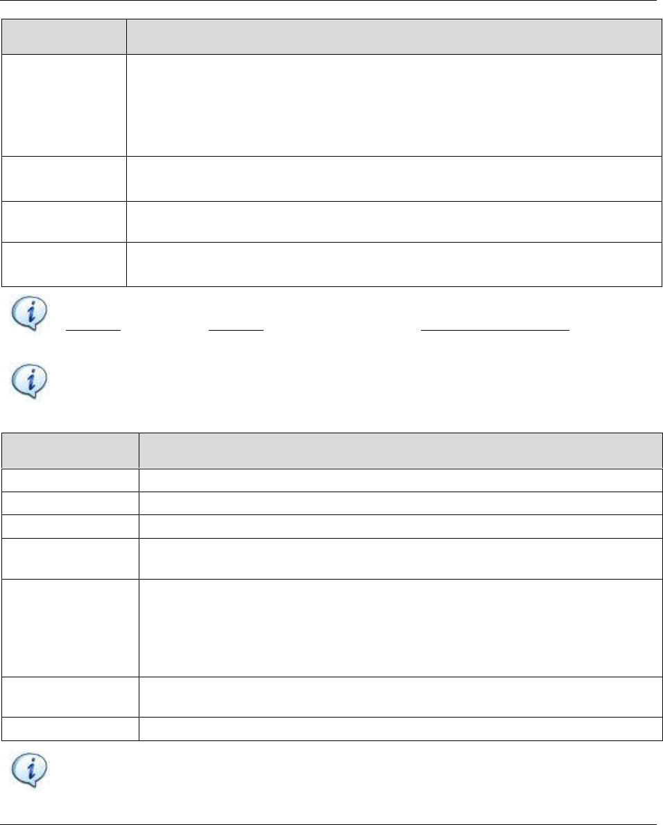
6.1 Stations Configuration
Device Files area
Focus 60 / Focus 61
connected
Click the minus or
plus symbols to
close or open
menus
Focus 60 / Focus 61 User Guide Programming Focus 60 / Focus 61
9839 0211 01 Edition 1.1 51 (106)
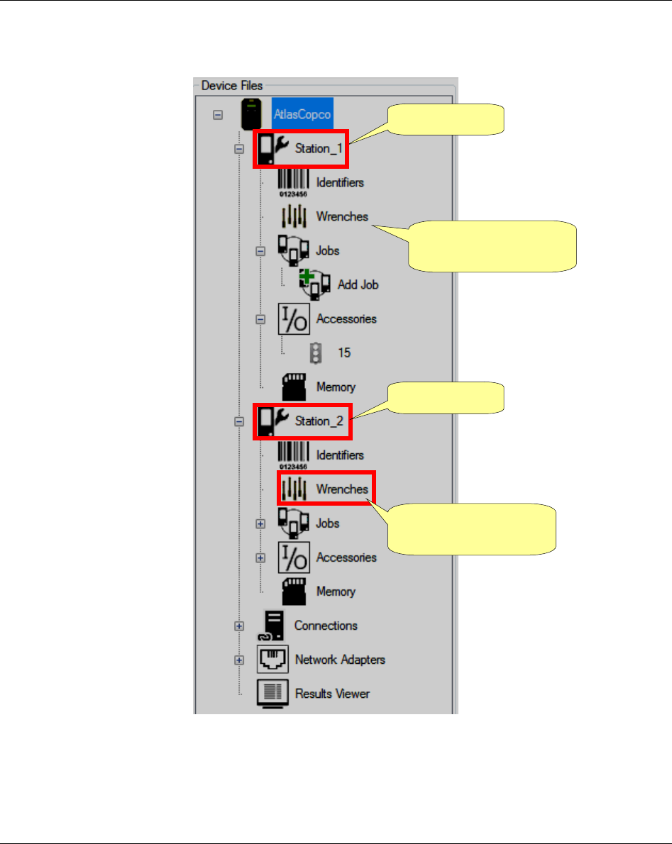
The Device Files area defines the stations associated with the Focus 60 / Focus 61 connected. For each
station there are MWR-TA associated, which execute the Jobs programmed.
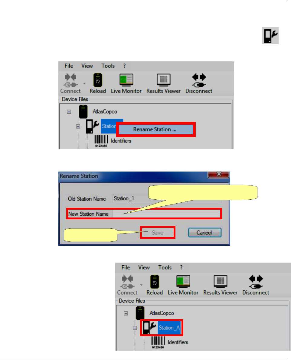
For renaming the Station associated with the Focus 60 / Focus 61 connected, right-click in
correspondence of the symbol placed close to each station name and shown on the right:
The following screen is shown:
After clicking “Rename Station …” the following screen shows:
Type the “New Station Name” in
correspondence of the respective text
box; then click Save.
Once it is done, the Station name in the
Device Files area is renamed according
to the new input (for instance, in this
case, “Station_A”):
1. Type the “New Station Name”
2. Click Save
Programming Focus 60 / Focus 61 Focus 60 / Focus 61 User Guide
52 (106) 9839 0211 01 Edition 1.1
6.2 Associating the MWR wrenches with Station(s)
It is possible to associated up to 10 MWR-TA with a Focus 61, divided into the two Stations (one MWR-
TA on one Station for Focus 60).
Station_1
MWR-TA associated
with Station_1
Station_2
MWR-TA associated
with Station_2
Focus 60 / Focus 61 User Guide Programming Focus 60 / Focus 61
9839 0211 01 Edition 1.1 53 (106)
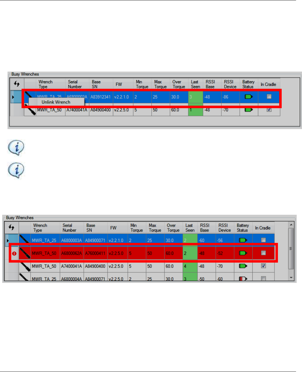
The Linked Wrenches section lists all the usable MWR-TA.
The MWR-TA shown as available or busy are only the MWR-TA powered on and visible from the
controller via radio.
Available Wrenches section
Busy Wrenches section
Linked Wrenches section
Programming Focus 60 / Focus 61 Focus 60 / Focus 61 User Guide
54 (106) 9839 0211 01 Edition 1.1
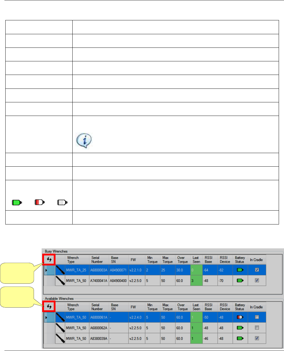
For each MWR-TA the following information are displayed:
Wrench Type
MWR-TA model
Serial Number
Serial number marked on the MWR wrench
Base SN
Serial number of the Focus 60 / Focus 61
FW
Firmware version loaded on the MWR-TA
Minimum Torque
Minimum torque values for the MWR-TA model
Maximum Torque
Maximum torque values for the MWR-TA model
Overload Torque
Maximum overload torque for the MWR-TA model
Last Seen
“Keep alive” mode of the MWR-TA by the controller
NOTE: This box is highlighted by different colors according to the
time of connection failure
RSSI Base
Received Signal Strenght Indication (indicated in dBm)
RSSI Device
Received Signal Strenght Indication of the Device (indicated in dBm)
Battery status
Green → Battery charge ok
Red → Battery charge low
Empty → MWR-TA not available (but already linked)
In Cradle
Activated if the MWR-TA is on the Charging Cradle MWR
Click the Refresh icons to refresh the list of wrenches both in the Busy Wrenches field and in the Available
Wrenches field:
Refresh
icon
Refresh
icon
Focus 60 / Focus 61 User Guide Programming Focus 60 / Focus 61
9839 0211 01 Edition 1.1 55 (106)
To associate a MWR-TA with a Station, drag one of the available MWR-TA and drop it into the Wrench
menu of the Station (refer to the figure below):
On the MWR-TA associated, the YELLOW LEDs are active.
NOTE: The following LEDs characterize the MWR-TA:
Yellow
Red
Green
Blue
For further details about MWR-TA LEDs, refer to the “MWR-TA and Charging Cradle MWR
User Guide”.
Drag the wrench icon from the
Available Wrenches section to the
wrench icon placed in Device
Files area
Programming Focus 60 / Focus 61 Focus 60 / Focus 61 User Guide
56 (106) 9839 0211 01 Edition 1.1
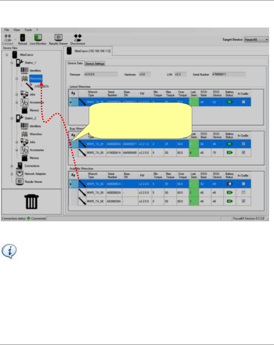
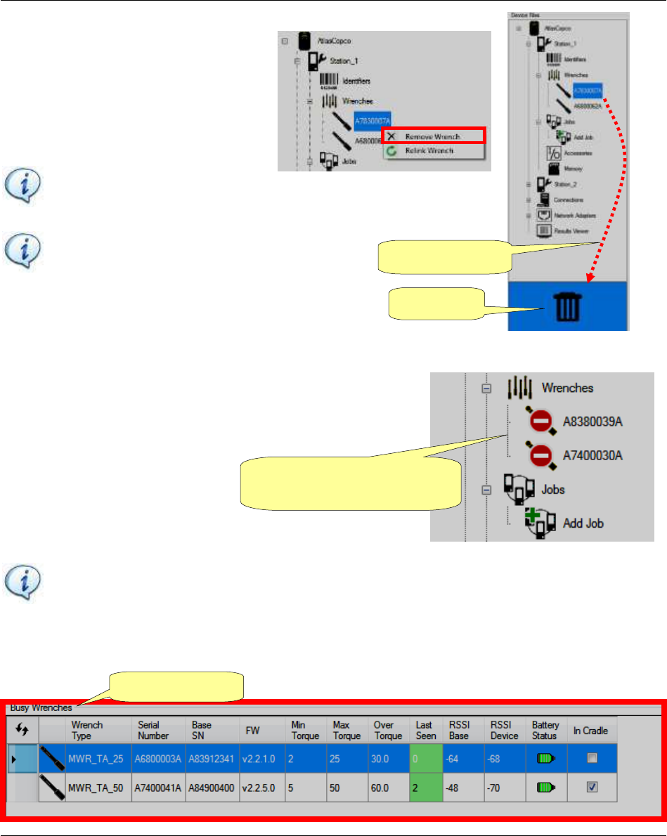
To remove a MWR-TA from the Station
either drag and drop it into the trash bin or
right-click and select Remove Wrench
(see the figure on the right):
The following icon (see the figure
on the right) marks the MWR-TA
associated with the Station, but not
connected:
NOTE: The status of the MWR-TA shown in the figure above is refreshed dinamically in real
time.
The MWR wrenches shown as Busy are associated to other Focus controllers.
NOTE: If a MWR-TA is not
used/linked to a job, then it can
be removed.
NOTE: Relink Wrench option
relinks the selected wrench to a
specific Station.
Trash bin
Drag and drop
MWR-TA powered off or out
of radio range
Busy Wrenches
Focus 60 / Focus 61 User Guide Programming Focus 60 / Focus 61
9839 0211 01 Edition 1.1 57 (106)
To make a “Busy Wrench” available:
Connect the controller that is associated with the wrench.
Remove the wrench.
In case that the controller is off or disconnected, it is possible to unlink the wrench by right-
clicking and selecting Unlink Wrench:
NOTE: The Unlink Wrench option does not work if the associated controller is on and in
radio range.
NOTE: Please, be sure that the wrench is not in use on the other controller. If it is, it can cause
malfunctions.
In some cases, a Busy Wrench is Red (see the picture below); it means that the controller has disassociated
the MWR-TA, but it has not yet received this warning because it is out of radio range.
Programming Focus 60 / Focus 61 Focus 60 / Focus 61 User Guide
58 (106) 9839 0211 01 Edition 1.1
6.3 Pset Configuration
The set of parameters that controls a tightening process is contained into a so-called Pset. This section
describes how to configure the Pset parameters necessary to do a tightening.
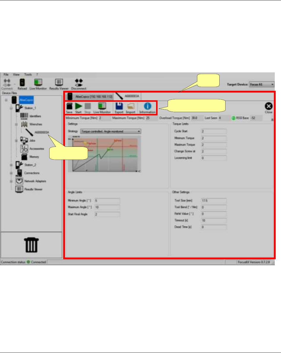
When a wrench is associated with a station while making a “double-click” on a MWR-TA, the page of the
associated Pset is shown:
Pset Toolbar
MWR-TA
Pset
Focus 60 / Focus 61 User Guide Programming Focus 60 / Focus 61
9839 0211 01 Edition 1.1 59 (106)
The Pset Toolbar (placed in the upper area of the above Pset window) provides the following functions:
ICON
FUNCTION
DESCRIPTION
Save
Save the Pset parameters
Start
Start the Pset on the MWR-TA.
Refer to the chapter “Executing Tightening Operations” for further
details
Stop
Stop the Pset execution
Live Monitor
Open the live results
window (see the figure on
the right):
Refer to the paragraph
“Live Monitor” for further
details
Export
Export the Pset in a .Pset file (formatted as xml)
Import
Load the Pset from the .Pset file exported previously
Information
General information about the MWR-TA connected with the Focus
60 / Focus 61.
After clicking Information icon, the following screen shows:
Calibration
Request area
Update
Wrench area
Download
Key Results
Programming Focus 60 / Focus 61 Focus 60 / Focus 61 User Guide
60 (106) 9839 0211 01 Edition 1.1
The Pset consists of the following parameters:
SETTINGS
FUNCTION
DESCRIPTION
Strategy
Hereunder is a list of available strategies:
Torque controlled: Only the torque is measured.
The test result is OK if the maximum torque applied during the tightening is
within the torque limits:
Torque controlled, angle monitored: Torque and angle are measured.
The test result is OK if the maximum torque applied during the tightening is
within the torque limits, and the angle is also within the angle limits:
Torque
Time
Maximum torque
Minimum torque
Torque
Angle
Maximum torque
Minimum torque
Min. angle
Max. angle
Focus 60 / Focus 61 User Guide Programming Focus 60 / Focus 61
9839 0211 01 Edition 1.1 61 (106)
TORQUE LIMITS
FUNCTION
DESCRIPTION
Cycle Start
Torque value from which the measurement of the tightening starts
Minimum torque and
Maximum torque
Torque limits to get a positive result
Change screw at
Torque limit for which the screw could be damaged by the excessive torque applied.
If the operator applies torque over this value, the result is marked as “OVSC =
Additional torque limit “overload screw” exceeded”
Loosening limit
If the operator applies torque in the wrong direction and reach this value, the
result is marked as “NEG = False direction of tightening (loosen)”.
NOTE: If the Loosening limit is set to zero, no results are detected (the
function is disabled).
ANGLE LIMITS
FUNCTION
DESCRIPTION
Minimum angle and
Maximum angle
Angle limits to get a positive result (if angle value is considered in the test
strategy).
Start final angle
Torque threshold from which the angle measurement starts.
OTHER SETTINGS
FUNCTION
DESCRIPTION
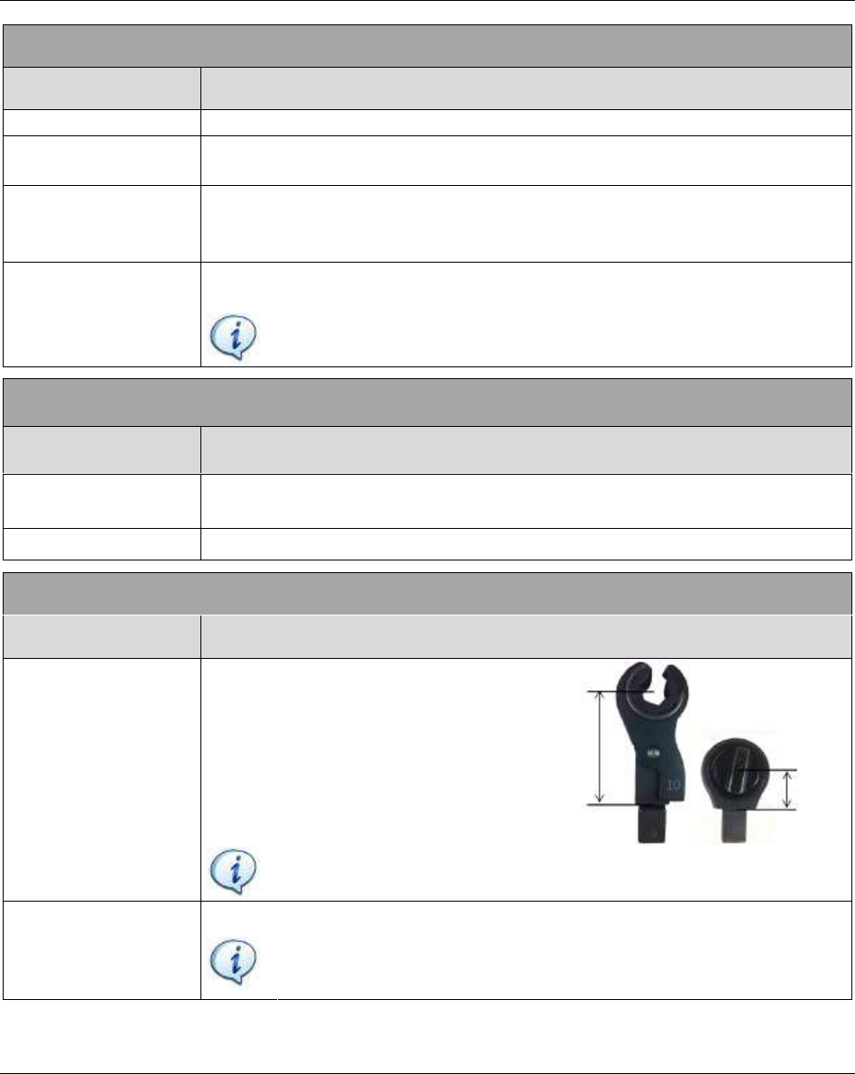
Tool size (mm)
Specific length (in millimeters) that
characterizes the end fitting tool
installed on the MWR-TA (see the
examples on the right):
NOTE: It is mandatory to enter the proper value. This value is used to
calculate the proper torque applied to the joint.
Tool Bend (° / Nm)
Bending of the end fitting tool installed on the MWR-TA.
NOTE: It is mandatory to enter the proper value. This value is used to
compensate the bending of the end fitting tool in the angle
measurement.
Tool
size
Tool size
Programming Focus 60 / Focus 61 Focus 60 / Focus 61 User Guide
62 (106) 9839 0211 01 Edition 1.1
FUNCTION
DESCRIPTION
Rehit Value (°)
If the torque reaches the click value within this angle, it means that the screw
was already tightened.
In this case the result is marked as RNOK or ROK .
NOTE: Refer to the paragraph “Executing Tightening Operations” for
further details about the results status.
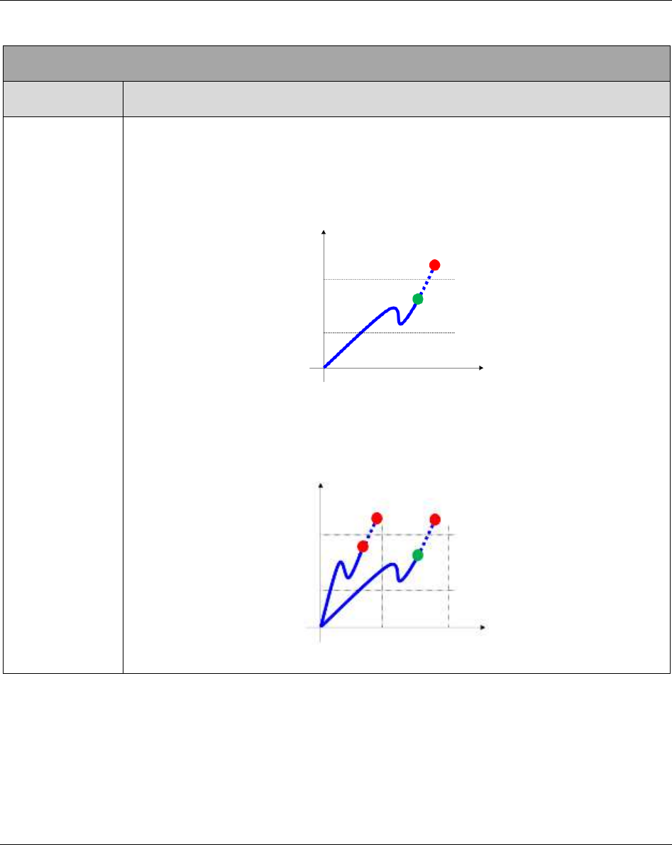
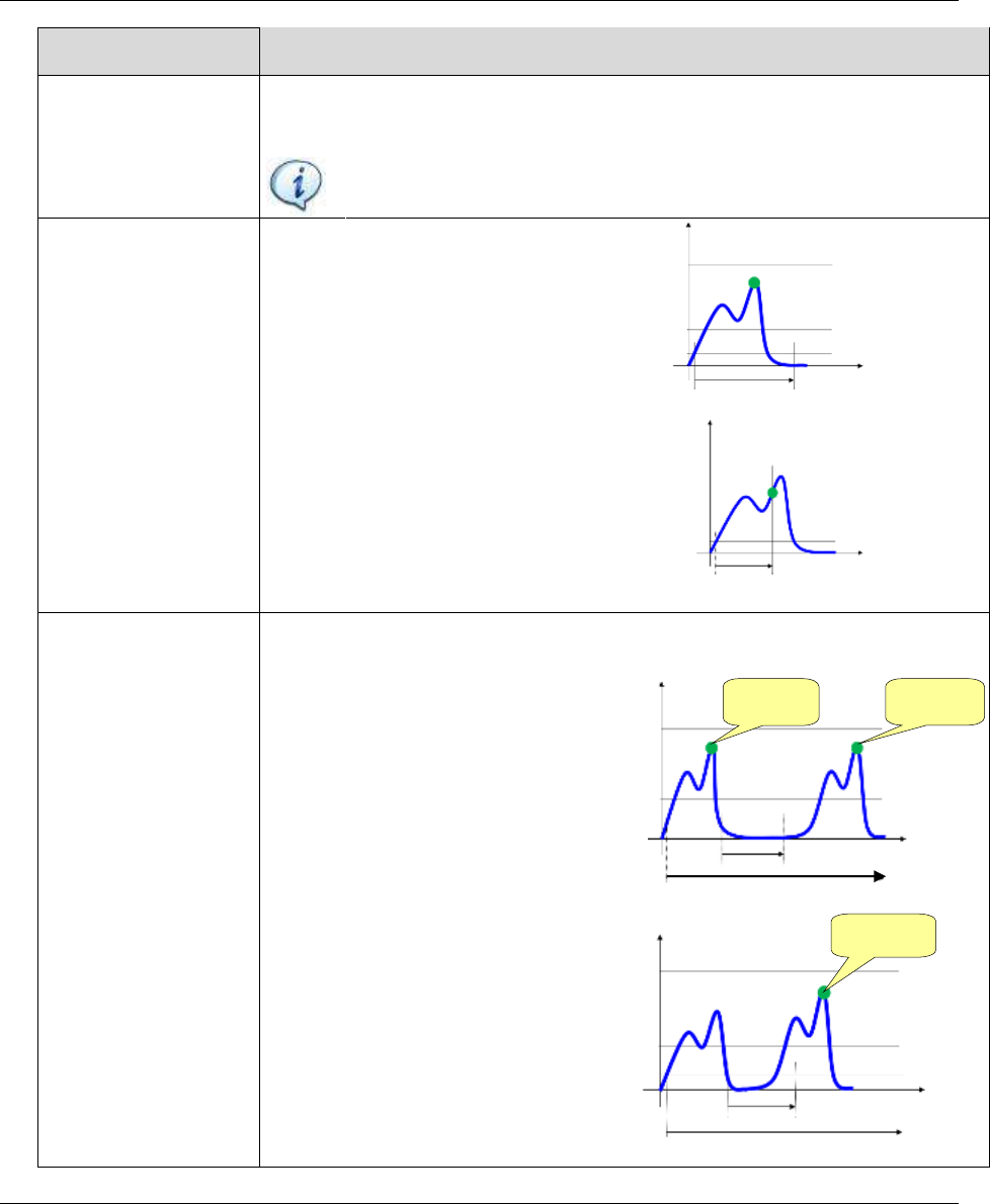
Timeout (s)
Maximum time (in seconds) of the
measurement (starting from the
moment that the torque reaches
the Cycle Start value).
The tightening operation should
be completed before the timeout
(see the figure on the right):
If the timeout is too short (or the
tightening too long) the result
might not be taken at the proper
maximum point:
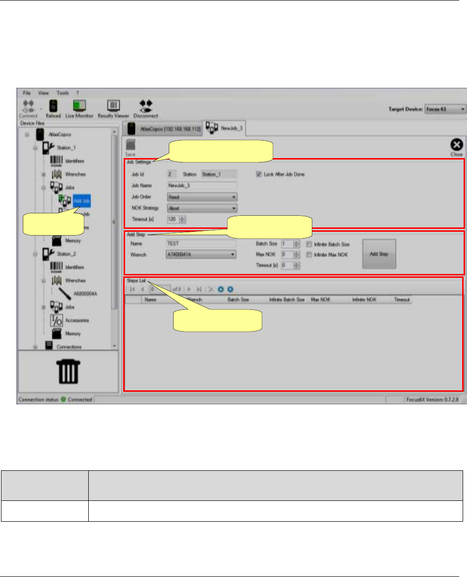
Dead Time (s)
Minimum time (in seconds) among two tightening operations. This timer starts
when the torque goes below
the Cycle Start value.
Start the new tightening
operation after the Dead
Time expires:
If the operator starts a new
tightening before the Dead
Time expires, the maximum
torque value of the whole
trace is analyzed (see the
figure on the right):
Time
Timeout
Torque
Cycle start
Torque
Time
Timeout
Cycle start
Time
Torque
Dead Time
Timeout
Result 1
Result 2
Time
Result 1
Dead Time
Cycle start
Timeout
Torque
Focus 60 / Focus 61 User Guide Programming Focus 60 / Focus 61
9839 0211 01 Edition 1.1 63 (106)
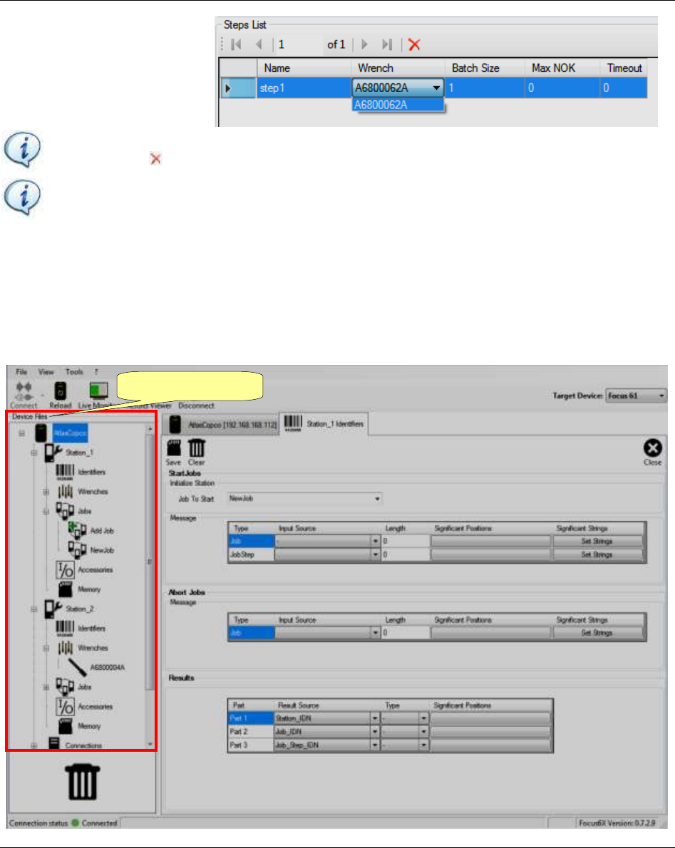
6.4 Job Configuration
The Job is a set of tightening operations (steps) performed by the MWR-TA associated with a station.
Each MWR-TA must be configured with its Pset as described in the paragraph above.
Double-click Add Job (see the figure above) to create a new Job.
To remove a Job either double-click and select Delete or drag and drop the Job into the trash bin.
Job Settings area configures the Job according to the following parameters:
PARAMETER
DESCRIPTION
Job Name
Name of the Job
Add Job
Steps List area
Job Settings area
Add Step area
Programming Focus 60 / Focus 61 Focus 60 / Focus 61 User Guide
64 (106) 9839 0211 01 Edition 1.1
PARAMETER
DESCRIPTION
Job Order
- Fixed: The Steps of the Job are executed in the order specified in the window above.
- Free: The Steps of the Job are executed according to the Optional Trigger
defined in the Step parameter. The Optional Trigger is a barcode string that
must be scanned before executing the step.
See below for further details about the Step parameters.
NOK Strategy
- Abort: If a Step is executed with Not OK result, the Job is aborted.
- Continue: If a Step is executed with Not OK result, the Job continues.
Timeout (s)
Maximum time (in seconds) to complete the Job. If it is equal to zero there is no
control on the time. By default it is set on 120 seconds
Lock After Job
Done
If enabled, the MWR-TA is locked at the end of the Job (the Job must start again to continue).
If disabled, a new Job starts automatically when the previous Job is complete.
NOTE: The total number of Jobs is equal to 1000. They are distributed as follows: 300 Jobs for
Station 1, 300 Jobs for Station 2 and 400 Jobs for global (shared between Stations).
At the end of the configuration, click Save.
NOTE: Save icon is disabled if there are no steps in the Job.
To add a Step, enter the parameters in the Add Step area and click Add Step:
PARAMETER
DESCRIPTION
Name
Step name
Wrench
Select the MWR-TA from the list of MWR-TA associated with the Station
Batch Size
Number of times/bolts that the Step works
Infinite Batch Size
Selecting “Infinitive batch Size” option, the Step works an infinite number of
times/bolts. This option disables “Batch size” setting
Max NOK
For each tightening of the batch, it specifies how many times the operator can
execute a test with Not OK result
For instance, if it is set to 2, the operator can repeat two times a wrong tightening;
at the 3rd Not OK, the batch stops and the Job continues or aborts depending from
the NOK Strategy parameter defined in the Job
Infinite Max NOK
Selecting “Infinitive Max NOK” option specifies that the operator can execute a
test with Not OK result infinitely. This option disables “Max NOK” setting
Timeout
Maximum time (in seconds) to start the Step from the moment the MWR-TA is ready to start
NOTE: The maximum permitted number of Steps (per Job) is equal to 100.
Focus 60 / Focus 61 User Guide Programming Focus 60 / Focus 61
9839 0211 01 Edition 1.1 65 (106)
The Steps List area shows all
of the Steps defined (see the
picture on the right).
NOTE: It is not possible to modify a step already saved. To remove a step, select it and click
Remove icon ( ).
NOTE: It is MANDATORY to disconnect the ToolsTalk BLM to use Focus 60/ Focus 61 and
start a Job.
6.5 Identifier
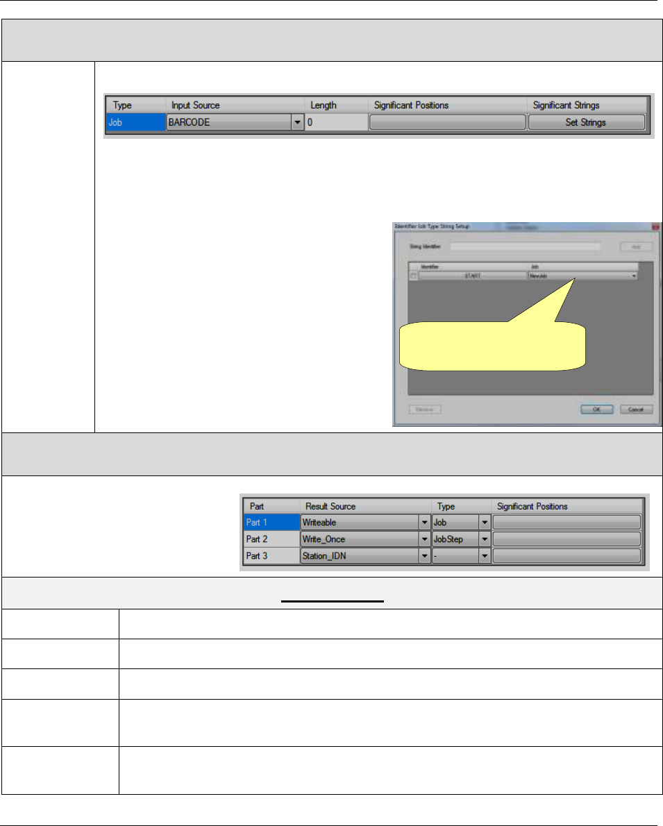
Identifier option can both start / abort a Jobs / Job steps and record tightenings results.
Double-click Identifier icon placed in the Device Files area in order to open the configuration window:
Device Files area
Programming Focus 60 / Focus 61 Focus 60 / Focus 61 User Guide
66 (106) 9839 0211 01 Edition 1.1
The following parameters configure the Identifier:
START JOBS
Initialize
station
Select the Job to use when the Focus 60 / Focus 61 is initialized.
Message
Message area selects the signal that start a Job / Job step.
Select the signal between the following options:
Barcode
AOP_setvin
AOP_Identifier
Define the following parameters:
Length: number of the characters of the input signal (barcode or AOP)
Significant Position: it defines the position of the characters that arranges the
substring that starts the Job/Job step
Significant String: click Set Strings button; the following window opens both for
Job and Job steps:
Steps list
Job Steps list: from the
menu select the step to use
Job list: from the menu
select the Job to use
Focus 60 / Focus 61 User Guide Programming Focus 60 / Focus 61
9839 0211 01 Edition 1.1 67 (106)
ABORT JOBS
Message
Message area selects the signal that stop a Job.
Select the signal between the following options:
Barcode
AOP_setvin
AOP_Identifier
Define the following parameters:
Length: the number of the characters
of the input signal (barcode or AOP)
Significant Position: the position of
the characters that makes the
substring that starts the Job
Significant String: click Set Strings
button; the pop-up on the right opens
for Job.
RESULTS
Results area defines the editable
information displayed in the results
table (for further details about the
results table, refer to the chapter
“Results Viewer”).
Results Source
Station_IDN
Station name
Job_IDN
Job name
Job_Step_IDN
Job Step name
Writable
The IDN may be changed anytime during the active job, but it may just be updated
during a Job Step start. An active Job Step is not affected.
Write_Once
The IDN can be set only once. Afterwards, all changes are rejected, except in the case
the Job ends or is aborted.
Job list: from the menu
select the Job to use
Programming Focus 60 / Focus 61 Focus 60 / Focus 61 User Guide
68 (106) 9839 0211 01 Edition 1.1
Type
Results Source Writable and Write_Once, define the command to use as reference (Job / JobStep) in
order to extract the results string.
Significant Position
It defines the position of the characters that arranges the substring of the command to use as result.
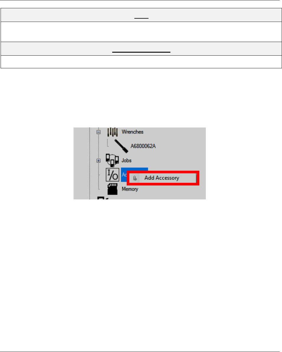
6.6 I/O Accessories
I/O Accessories option configures the accessories utilized during the Focus 60 / Focus 61 operations.
Right-click the I/O Accessories icon placed in the Device Files area in order to open the New Accessory
menu:
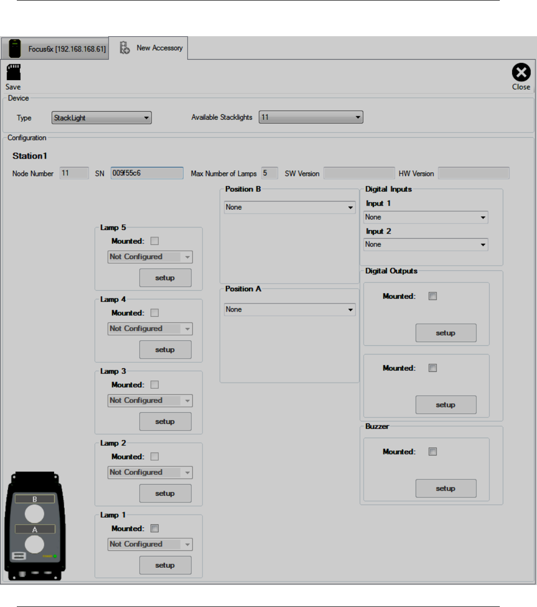
Focus 60 / Focus 61 User Guide Programming Focus 60 / Focus 61
9839 0211 01 Edition 1.1 69 (106)
After selecting Add Accessory, the following window shows:
Programming Focus 60 / Focus 61 Focus 60 / Focus 61 User Guide
70 (106) 9839 0211 01 Edition 1.1
DEVICE
Type
Accessory used
Available
Stacklights
This drop-down list selects the ID channel to use in order to configure the
accessory
CONFIGURATION
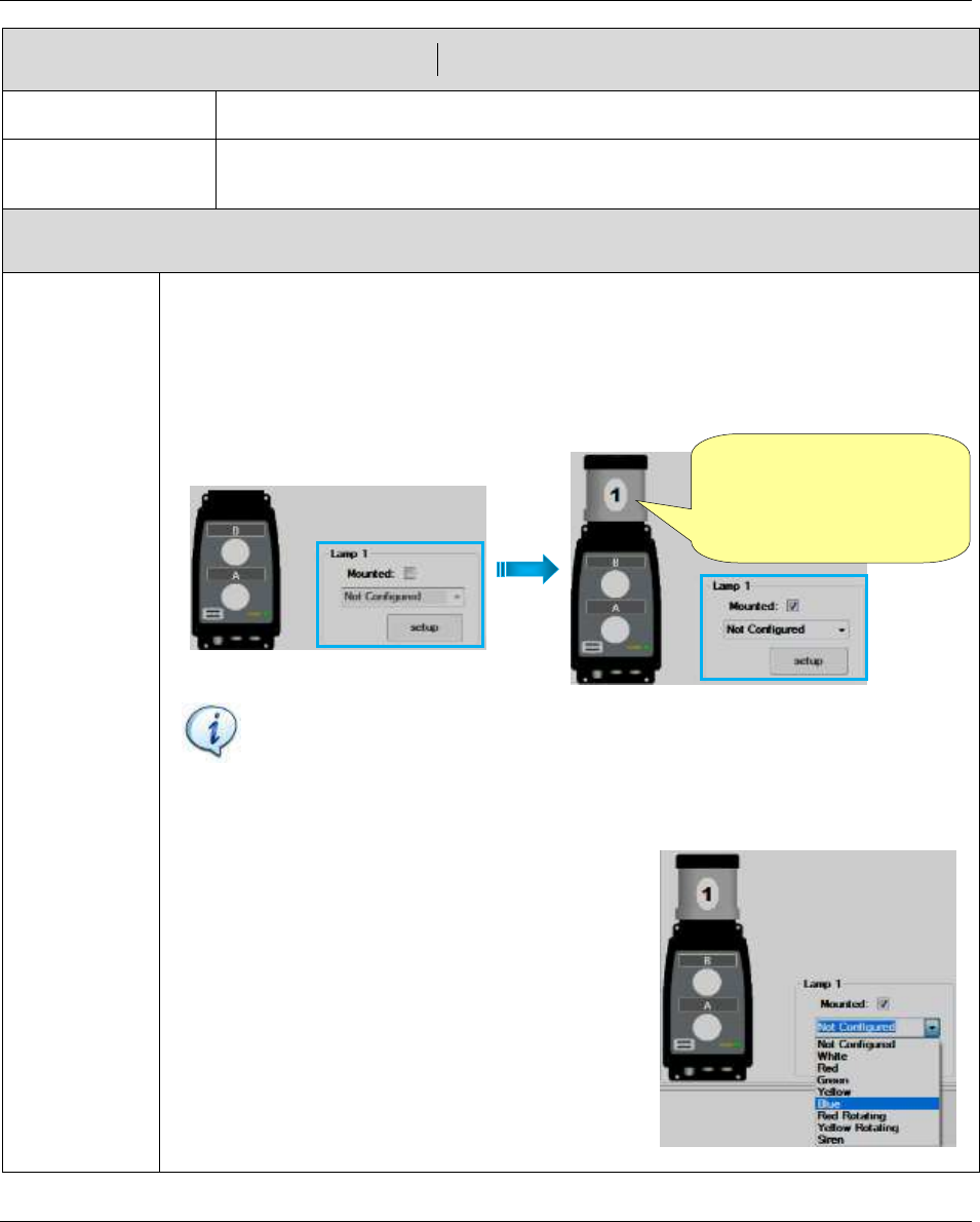
Lamp
“Lamp” section configures the behavior of each lamp. The Stacklight mounts up to 5
configurable lamps.
Do the following procedure to configure “Lamp” section.
1. Starting from Lamp 1, check the box in correspondence of “Mounted”: a lamp
shows on the Stacklight on the left (see the figures below):
NOTE: Configure the lamps of the Stacklight starting from lamp 1 to lamp 5
(in ascending order). Only the last configured lamp is editable.
For instance, after configuring all of the lamps, to edit lamp 3, it is necessary
to disable the last configured lamps in this sequence: lamp 5 – lamp 4.
To disable a lamp, remove the check mark in correspondence of “Mounted”.
2. Open the drop-down list (placed below
“Mounted” option) and select between the
following options:
Not Configured, White, Red, Green, Yellow,
Blue, Red Rotating, Yellow Rotating, Siren.
After setting the configuration, the lamp on the
Stacklight is automatically colored according to
the option selected.
After checking the box
in correspondence of
“Mounted”, a lamp
shows on the Stacklight
Focus 60 / Focus 61 User Guide Programming Focus 60 / Focus 61
9839 0211 01 Edition 1.1 71 (106)
CONFIGURATION
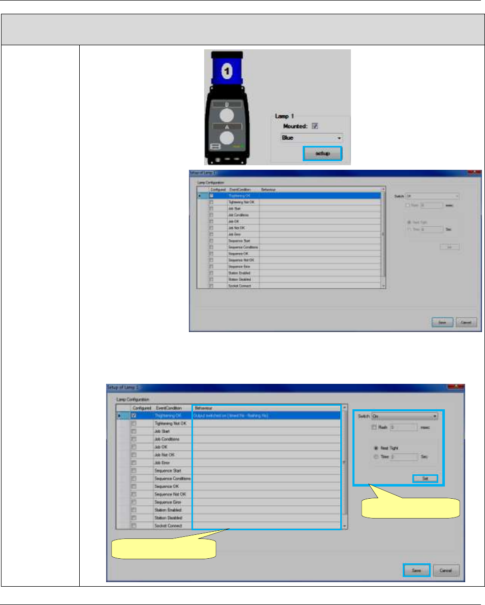
3. Click Setup:
The Setup screen
on the right
shows:
4. Select the event condition to associate with the lamp. After selecting the event
condition, the editable section on the right of the Setup screen gets automatically
active (refer to the following screen):
Editable section
Behaviour column
Programming Focus 60 / Focus 61 Focus 60 / Focus 61 User Guide
72 (106) 9839 0211 01 Edition 1.1
CONFIGURATION
The “Behaviuor column” summarizes the editable section.
Configure the editable section by setting temporary intervals of flashes and signal
duration. Finally click Set (placed on the lower right corner of the editable section).
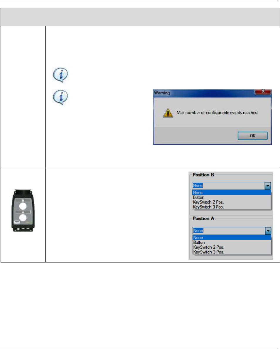
It is possible to set up to 10 event conditions for the same lamp.
NOTE: It is not recommended selecting event conditions that do not agree on
the same lamp (for instance Tightening OK and Tightening NOK).
NOTE: The pop-up on the
right shows, after reaching
the maximum number of
configurable events:
After configuring the necessary event conditions, click Save (placed on the lower
right corner of the Setup screen).
Position A / B
Position A / B on the Stacklight (refer to the figure
in the left column) defines an input type between
the following options:
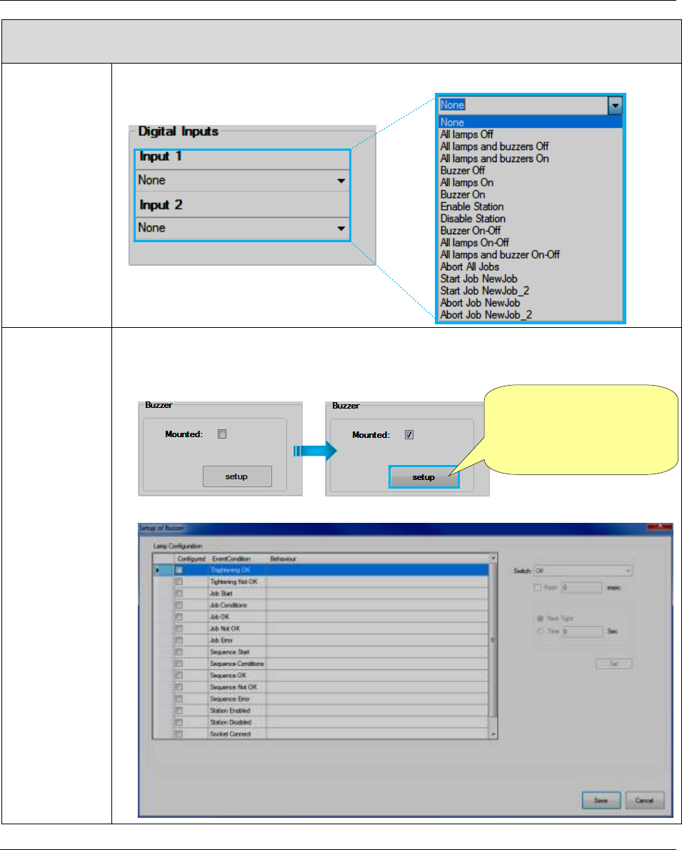
Focus 60 / Focus 61 User Guide Programming Focus 60 / Focus 61
9839 0211 01 Edition 1.1 73 (106)
CONFIGURATION
Digital Inputs
The external device sends one of the following signals to the Stacklight:
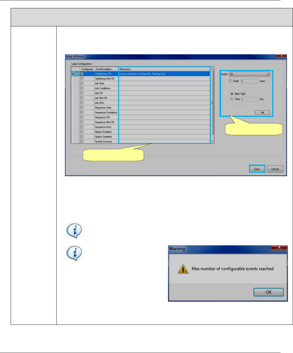
Buzzer
Do the following procedure to configure “Buzzer” section.
1. Check the box in correspondence of “Mounted”; the Setup button gets automatically
active (refer to the following screen):
2. Click Setup. The following Setup screen shows:
After checking the box
in correspondence of
“Mounted”, Setup button
gets automatically active
Programming Focus 60 / Focus 61 Focus 60 / Focus 61 User Guide
74 (106) 9839 0211 01 Edition 1.1
CONFIGURATION
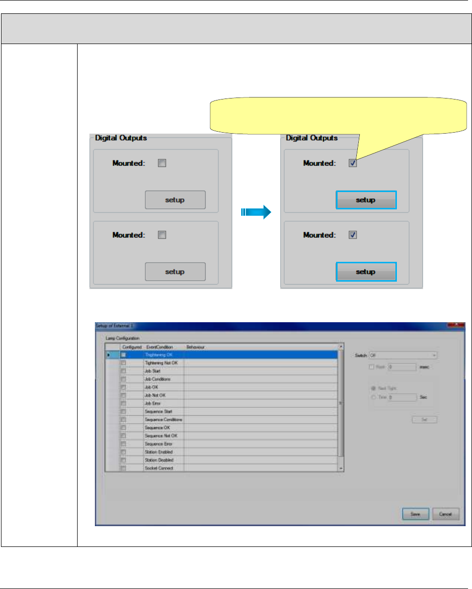
3. Select the event condition. After selecting the event condition, the editable section
on the right of the Setup screen gets automatically active (refer to the following
screen):
The “Behaviuor column” summarizes the editable section.
Configure the editable section by setting temporary intervals of flashes and signal
duration. Finally click Set (placed on the lower right corner of the editable section).
It is possible to set up to 10 event conditions.
NOTE: It is not recommended selecting event conditions that do not agree
(for instance Tightening OK and Tightening NOK).
NOTE: The pop-up on the
right shows, after reaching
the maximum number of
configurable events:
After configuring the necessary event conditions, click Save (placed on the lower
right corner of the Setup screen).
Editable section
Behaviour column
Focus 60 / Focus 61 User Guide Programming Focus 60 / Focus 61
9839 0211 01 Edition 1.1 75 (106)
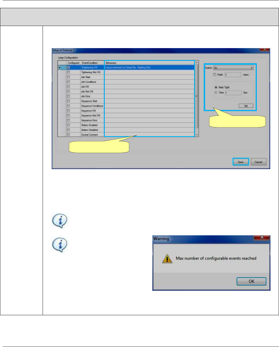
CONFIGURATION
Digital
Outputs
Do the following procedure to configure “Digital Outputs” section.
1. Check the box in correspondence of “Mounted”; the Setup button gets automatically
active (refer to the following screen):
2. Click Setup. The following Setup screen shows:
After checking the box in correspondence of
“Mounted”, Setup button gets automatically active
Programming Focus 60 / Focus 61 Focus 60 / Focus 61 User Guide
76 (106) 9839 0211 01 Edition 1.1
CONFIGURATION
3. Select the event condition. After selecting the event condition, the editable section on
the right of the Setup screen gets automatically active (refer to the following screen):
The “Behaviuor column” summarizes the editable section.
Configure the editable section by setting temporary intervals of flashes and signal
duration. Finally click Set (placed on the lower right corner of the editable section).
It is possible to set up to 10 event conditions.
NOTE: It is not recommended selecting event conditions that do not agree
(for instance Tightening OK and Tightening NOK).
NOTE: The pop-up on the
right shows, after reaching
the maximum number of
configurable events:
After configuring the necessary event conditions, click Save (placed on the lower
right corner of the Setup screen).
After setting the Stacklight, click Save (placed on the upper left corner of the New Accessory window).
Editable section
Behaviour column
Focus 60 / Focus 61 User Guide Executing Tightening Operations
9839 0211 01 Edition 1.1 77 (106)
7 EXECUTING TIGHTENING OPERATIONS
NOTE: No effects resulting from special conditions should be detected when the Focus 60 /
Focus 61 is integrated into systems.
Once the Focus 61 is configured as described in the previous paragraph “Programming Focus 60 / Focus
61”, it is possible to start a Job on the Station(s).
On each station, only one MWR-TA can work at a time.
The Job associated with each MWR-TA starts depending from the Event settings.
NOTE: Refer to the paragraph “Associating the MWR wrenches with Station(s)” for further
details about the LED indication on the MWR-TA.
The tightening results are visible on
the Focus 60 / Focus 61 display and
on the stacklight (see the figure on
the right).
MWR-TA ready
Start Event
Execute the tightening,
when blue LED flashes
Stacklight
Test result
Executing Tightening Operations Focus 60 / Focus 61 User Guide
78 (106) 9839 0211 01 Edition 1.1
The Focus 60 / Focus 61 display shows the tightening result of the last tightening:
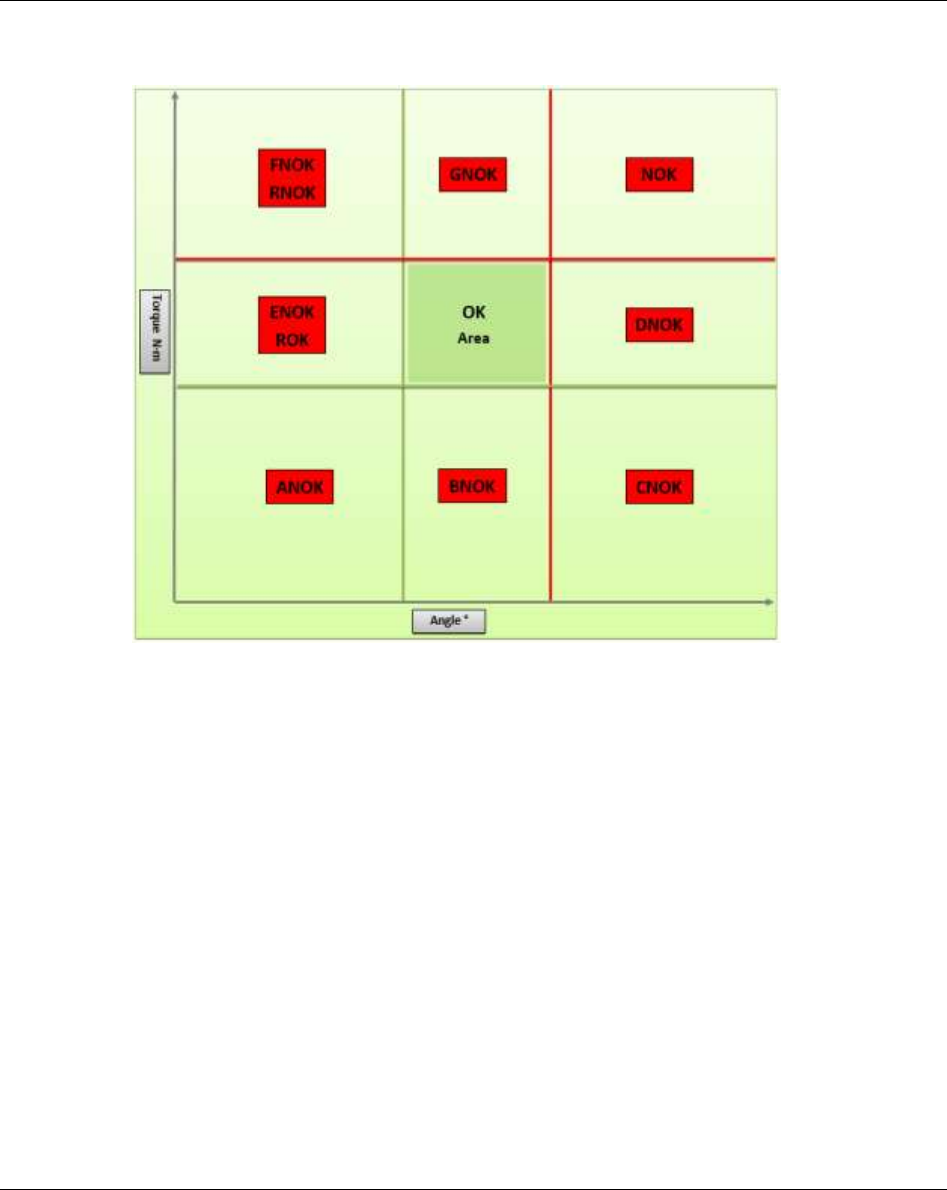
Refer to the following results status list for possible results status that can be shown on the Focus 60 /
Focus 61 display:
OK = Torque and angle within the limits (OK)
NOK = Torque and angle above the limits (Not OK)
LCK = Wrench locked
ANOK = Torque and angle below the limits (Not OK)
BNOK = Torque below the limits, angle within the limits (Not OK)
CNOK = Torque below the limits, angle above the limits (Not OK)
DNOK = Torque within the limits, angle above the limits (Not OK)
ENOK = Torque within the limits, angle below the limits (Not OK)
FNOK = Torque above the limits, angle below the limits (Not OK)
GNOK = Torque above the limits, angle within the limits (Not OK)
ROK = Existing fitting (double hit), torque within the limits
RNOK = Existing fitting (double hit), torque above the limits
NEG = False direction of tightening (loosen)
OVSC = Additional torque limit “overload screw” exceeded
OVLD = Overload value of the wrench exceeded! Check calibration urgently!
TNOK = Timeout expired, torque / angle are not OK
TOK = Timeout expired, torque / angle are OK
OVAR = Maximum angular speed exceeded / it needs to be calibrated (Not OK)
OVAD = Reading outside of the AD converter range (Not OK)
Torque peak
Torque click
Angle
Status
Batch counter
MWR-TA
serial number
Focus 60 / Focus 61 User Guide Executing Tightening Operations
9839 0211 01 Edition 1.1 79 (106)
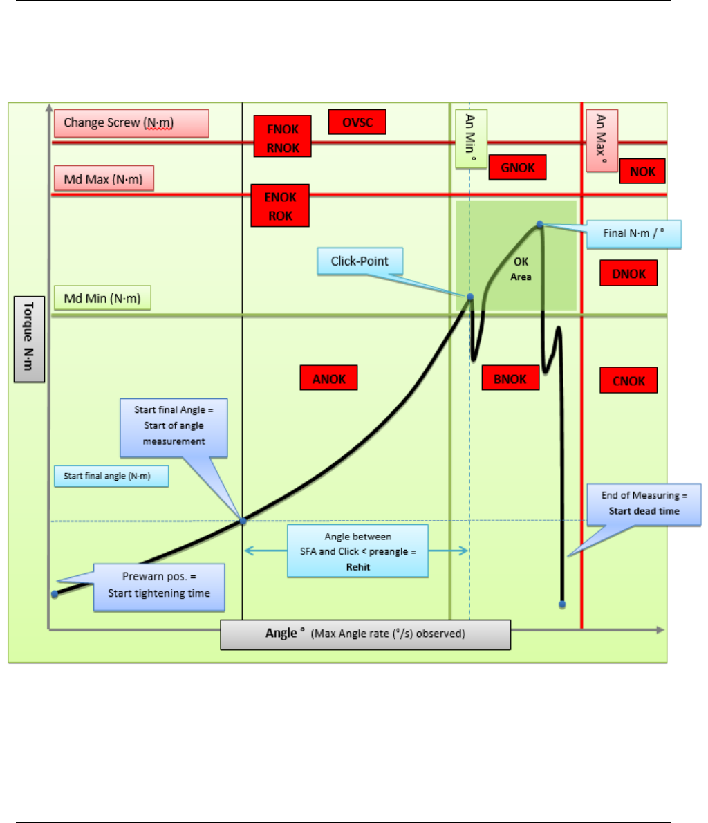
The following “Torque – Angle” graph shows all relevant Parameters Settings values.
According to them, the following example points the fields out that detect the results status above
mentioned:
Executing Tightening Operations Focus 60 / Focus 61 User Guide
80 (106) 9839 0211 01 Edition 1.1
More precisely:
Focus 60 / Focus 61 User Guide Live Monitor
9839 0211 01 Edition 1.1 81 (106)
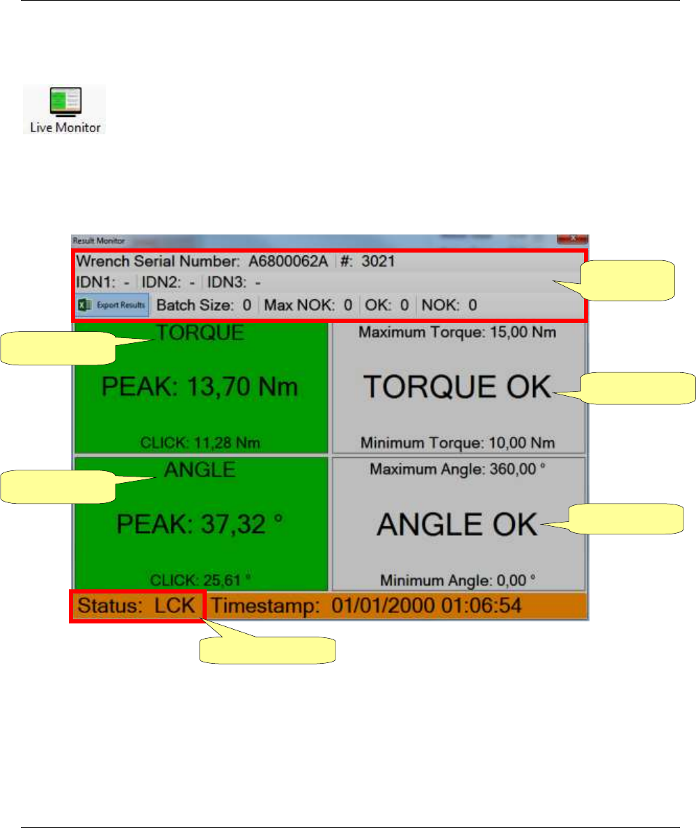
8 LIVE MONITOR
The Live Monitor icon shows in real time the tightening results of the MWR-TA
connected with ToolsTalk BLM.
After clicking Live Monitor, after executing a tightening with a linked MWR-TA, the following screen
shows:
Torque result
Angle result
Torque status
Angle status
General
Information
Tightening status

Live Monitor Focus 60 / Focus 61 User Guide
82 (106) 9839 0211 01 Edition 1.1
Hereunder are the fields displayed in the above Result Monitor screen:
FUNCTION
DESCRIPTION
Wrench serial number
Serial number of the MWR-TA
#
Result ID
IDN1: IDN2: IDN3:
IDN defined in the Job
NOTE: If the ToolsTalk BLM is connected, the IDN is NOT
visible.
Export Results
This option exports in an Excel file the results displayed in a tightenings session
Batch Size, Max NOK
Pset parameters set for the MWR-TA
OK, NOK
Number of tightening operations with OK and Not OK results
Torque result and Angle
Result
Peak and click torque/angle values of the last tightening operation.
The boxes are green colored if the torque/angle peaks are between the
minimum and maximum values defined in the MWR-TA Pset; otherwise
they are red colored
Torque Status and Angle
Status
This box shows the status and the limits defined in the MWR-TA Pset.
The status can be:
- Waiting…: Live results monitor open, but no results available yet
- Low: Torque/Angle lower than the minimum value
- OK: Torque/Angle within the limits
- High: Torque/Angle higher than the maximum value
Status
Overall status of the tightening operation.
Refer to the paragraph “Executing Tightening Operations” for further
details about the code shown here.
The box is green if the Status is OK, yellow if the MWR-TA is locked,
red if the Status is Not OK.
Timestamp
Date and time
NOTE: In case two MWR-TA on two different stations generate a result at the same time, only
the last one is visible on the Live Monitor interface.
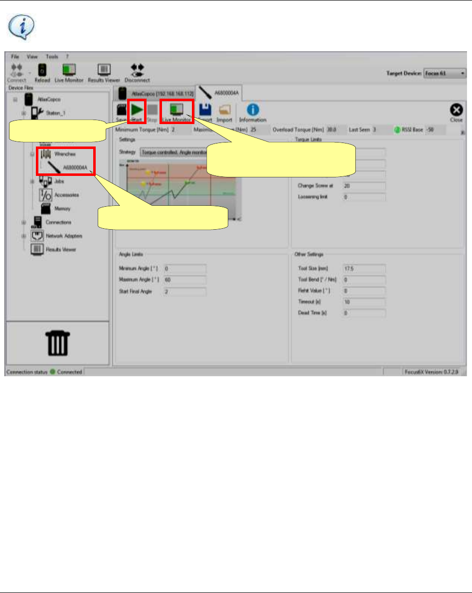
Focus 60 / Focus 61 User Guide Live Monitor
9839 0211 01 Edition 1.1 83 (106)
NOTE: For Psets executed directly on the MWR-TA, it is possible to open a Live Monitor
interface for each MWR-TA:
2. Start the Pset
3. Live results monitor for the
selected MWR-TA
1. Select the MWR-TA
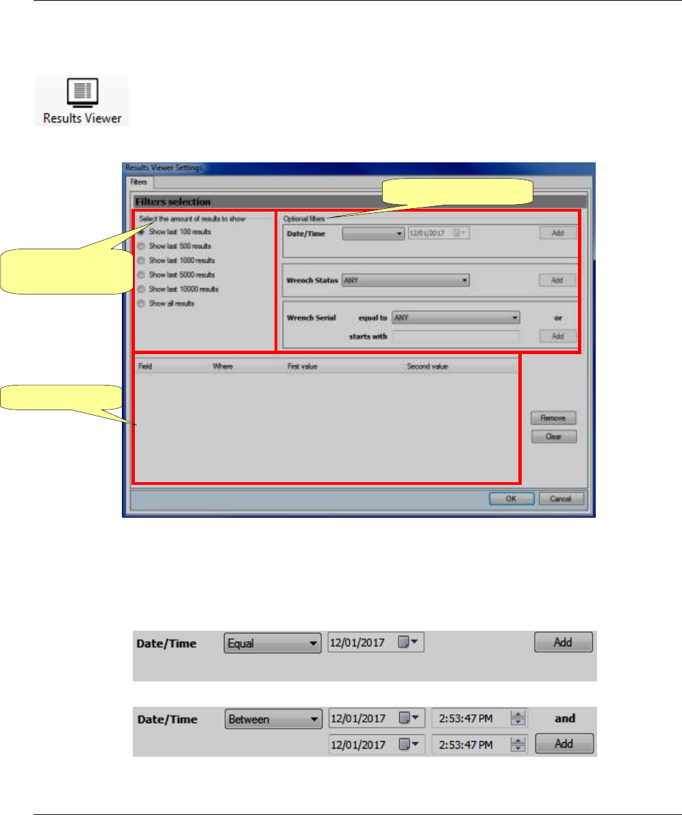
Results Viewer Focus 60 / Focus 61 User Guide
84 (106) 9839 0211 01 Edition 1.1
9 RESULTS VIEWER
The Results Viewer icon shows a list of the tightening results of all MWR-TA connected
with ToolsTalk BLM.
After clicking Results Viewer, the following Filters selection pop-up shows:
Select the amount of results to show, by acting on the left side of the above pop-up.
Set Date/time filter, Wrench Status filter and Wrench Serial filter in the Optional filters area.
Date/time filter: click the drop-down list and select between “Equal” or “Between”.
“Equal” option filters results measured in a specified day.
“Between” option filters results according to a defined time interval:
After setting Date/time filter, click Add.
Select the amount
of results to show
Optional filters area
Summary area
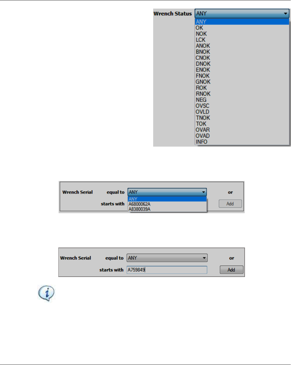
Focus 60 / Focus 61 User Guide Results Viewer
9839 0211 01 Edition 1.1 85 (106)
Wrench Status filter: click the drop-down list
and select between the results status list (see
the list on the right):
After setting Wrench Status filter, click Add.
Wrench Serial filter: set the Wrench Serial filter with one of the following procedures.
o Click the drop-down list in correspondence of “equal to” in order to show the Serial numbers
of the wrenches connected with one of the two Stations. Select one Wrench Serial.
o Keep ANY on the drop-down list placed in correspondence of “equal to”. Manually insert the
Serial number of the necessary wrench in correspondence of “starts with”. This function
examines Serial numbers also if they are partially inserted into the related text box, provided
that the partial Serial number starts from the first digit.
NOTE: Use either the first or the second procedure above given.
After setting Wrench Serial filter, click Add.
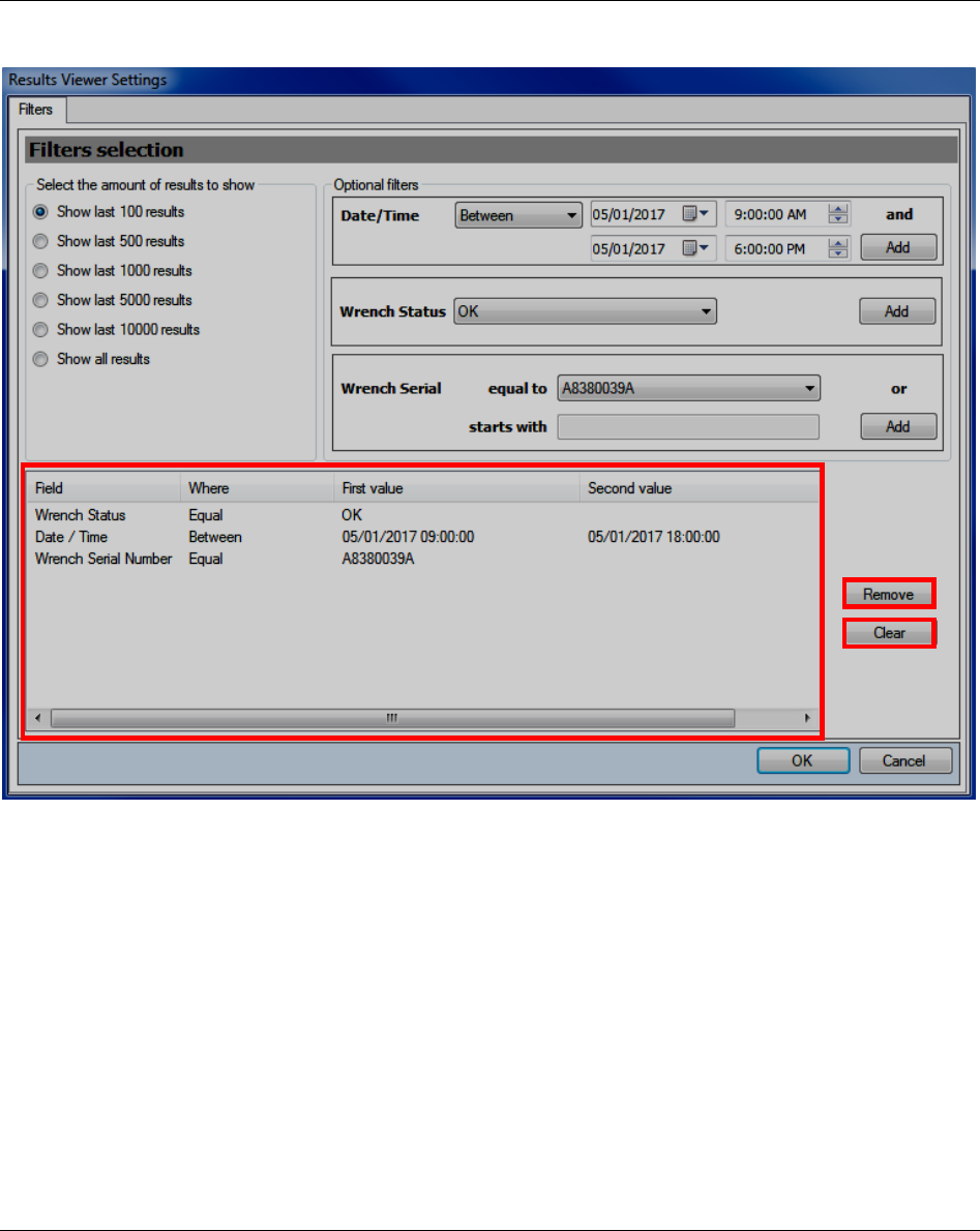
Results Viewer Focus 60 / Focus 61 User Guide
86 (106) 9839 0211 01 Edition 1.1
The summary area is automatically filled (see the following screen).
“Remove” button (placed on the right of the Summary area) removes the filters inserted in the Summary
area singularly.
“Clear” button (placed below “Remove” button) removes all of the filters inserted in the Summary area at
the same time.

Focus 60 / Focus 61 User Guide Results Viewer
9839 0211 01 Edition 1.1 87 (106)
After recording the Filters selection pop-up, click OK; the following screen shows:
Load results icon
Results Viewer Focus 60 / Focus 61 User Guide
88 (106) 9839 0211 01 Edition 1.1
Click Load Results icon to load the results set previously; the following results list shows:
The Results Viewer toolbar shows the following commands:
Load Results icon
It loads all the results set in the Filters selection pop-up
Result Filters
It opens the Filters selection pop-up in order to modify the filters set
previously
Device Filters Set
The Set Filters drop down menu is Read Only. It lists the Tightening and
Results Filters Settings selected into the Device Settings page (for further
details, refer to the paragraph “Tightening and Results Filters Settings”)
Export
This option exports in an Excel file the Results List
Results Viewer toolbar
Focus 60 / Focus 61 User Guide Focus 60 / Focus 61 Settings
9839 0211 01 Edition 1.1 89 (106)
10 Focus 60 / Focus 61 SETTINGS
10.1 Device Data
The Device Data indicates the main features of the Focus 60 / Focus 61.
Firmware
Firmware version loaded on the Focus 60 / Focus 61
Hardware
Hardware version of the Focus 60 / Focus 61
LAN
LAN version of the Focus 60 / Focus 61
Serial Number
Focus 60 / Focus 61serial number
NOTE: When programming the Focus 60 / Focus 61 from ToolsTalk BLM, ensure that the
Focus 60 / Focus 61 is in the main menu.
10.2 Device Settings
Device Settings page sets the
parameters that characterize the
Focus 60 / Focus 61.
Focus 60 / Focus 61 Settings Focus 60 / Focus 61 User Guide
90 (106) 9839 0211 01 Edition 1.1
10.2.1 Focus 60 / Focus 61 Basic settings
Basic Settings select the following features:
Language: it selects the Focus 60 / Focus 61 language from the related list (refer to the screen
below). Click “Set Language” to confirm:
Measuring unit: it selects the Focus 60 / Focus 61 measurement unit from the related list (refer to the
screen below). Click “Set Measuring Unit” to confirm:
Time Sync: it selects the Time Sync from the related list (refer to the screen below). Click “Set Time
Sync” to confirm:
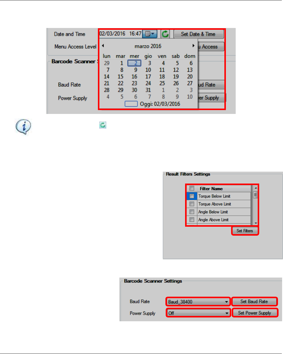
Focus 60 / Focus 61 User Guide Focus 60 / Focus 61 Settings
9839 0211 01 Edition 1.1 91 (106)
Date and time: It selects the Focus 60 / Focus 61 Date and Time from the related section (refer to the
screen below). Click “Set Date & Time” to confirm:
NOTE: Click the icon to match the time set on the PC with the time of the Focus 60 /
Focus 61.
10.2.2 Result Filters Settings
Select the Filter(s) to set on the results stored by the Focus
60 / Focus 61 from the related list placed in the Result
Filters Settings (refer to the screen on the right) and click
“Set Filters” to confirm:
10.2.3 Barcode Scanner Settings
Select both the Baud Rate and Power
Supply in order to set the Focus 60 /
Focus 61 from Barcode Scanner Settings
(refer to the screen on the right) and click
respectively “Set Baud Rate” and “Set
Power Supply” to confirm:
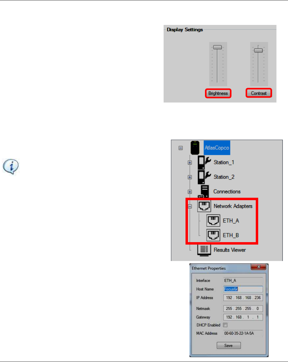
Focus 60 / Focus 61 Settings Focus 60 / Focus 61 User Guide
92 (106) 9839 0211 01 Edition 1.1
10.2.4 Display Settings
Set both the Brightness and Contrast on the Focus 60 /
Focus 61 from the related section placed in the Display
Settings (refer to the screen below) and click respectively
“Brightness” and “Contrast” to confirm:
10.3 Network Adapters Configuration
The Network Adapters menu (place in the Device Files area)
configures the Ethernet Ports A and B.
NOTE: It is MANDATORY to connect the Focus
60 / Focus 61 with ToolsTalk BLM before to
access the Network Adapters Configuration.
Select ETH_A or ETH_B option. This ports are defined in
the reference protocol.
The Ethernet Properties pop-up on the right shows:
Configure the Network Parameters (IP Address, Netmask,
Gateway), enable or disable the DHCP and click Save to confirm.
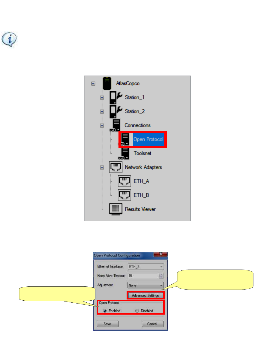
Focus 60 / Focus 61 User Guide Working with Open Protocol
9839 0211 01 Edition 1.1 93 (106)
11 WORKING WITH Open Protocol
NOTE: Compatible Atlas Open Protocol (AOP): 1.6.3
Atlas Open Protocol (AOP) is a communication protocol that interfaces directly with the Focus 61.
To enable this application, double-click the Open Protocol icon placed in the Device Files area (refer to
the picture above: Connections section); the following pop-up shows:
2. Enable Open Protocol
2. Click Advanced
Settings option
1. Enable Open Protocol
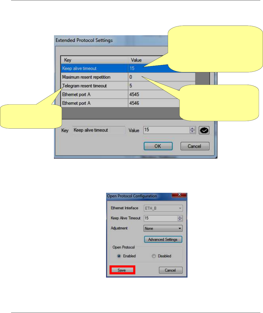
Working with Open Protocol Focus 60 / Focus 61 User Guide
94 (106) 9839 0211 01 Edition 1.1
After enabling the Open Protocol (by clicking Enabled box placed in Open Protocol section – refer to the
screen above), it is possible to access the Advanced Settings (by clicking Advanced Settings button):
After setting the Extended Protocol Settings, click OK; finally click Save in the below pop-up:
If no reply will be received,
the telegram acknowledge is
transmitted again a number of
times equal to the Maximum
resent repetition
Timeframe within a
telegram acknowledge
needs to be received
The application needs to send a
telegram at least every 10 s in order
to keep the connection established. If
no telegram is being received in
time, the connection is closed by the
controller

Focus 60 / Focus 61 User Guide Working with Open Protocol
9839 0211 01 Edition 1.1 95 (106)
11.1 Getting Result via Atlas Open Protocol
By the message “MID 0001 – Communication start”, a third application can start to communicate via
Atlas Open Protocol with the Focus 61; the reply (MID 0002) contains the basic information about the
controller.
Through the message “MID 0060 – Last tightening result data subscribe”, it is possible to make a
subscription.
NOTE: It is MANDATORY to specify into the message MID 0060 the Station ID (0 or 1).
From the subscription, all the tightening results performed will be sent to the Atlas Open Protocol
application automatically by the message MID 0061.
NOTE: When the application does not want any further data from the Focus 61, it sends to the
controller the message “MID 0063- Last tightening result data unsubscribe”.
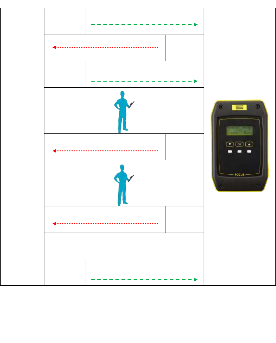
Working with Open Protocol Focus 60 / Focus 61 User Guide
96 (106) 9839 0211 01 Edition 1.1
Atlas Open Protocol
First Step
MID 0001 – Communication start
MID 0002
Second
Step
Third
Step
MID 0060 – Last tightening result data
subscribe
MID 0061
Fourth
Step
MID 0061
Fourth
Step
•••••••••••••••
Fifth Step
MID 0063- Last tightening result data
unsubscribe
Focus 60 / Focus 61 User Guide Working with Open Protocol
9839 0211 01 Edition 1.1 97 (106)
11.2 Starting a Job via Atlas Open Protocol by means of
VIN or Identifier
By the message “MID 0001 – Communication start”, the Atlas Open Protocol starts to communicate with
the Focus 61; the reply (MID 0002) contains the basic information about the controller.
Through the message “MID 0050 – Vehicle ID Number download request”, it is possible to trigger an
event (configured in the Focus 61) in order to start a Job.
NOTE: It is MANDATORY to specify into the message MID 0050 the Station ID (0 or 1).
Before sending this message from the Atlas Open Protocol to the Focus 61, there are some mandatory
steps to satisfy.
First, configure a Job to associate with the Event (refer to the paragraph “Job Configuration”).
Second, configure an Event:
- Event Type must be either AOP_SETVIN
- Station action must be set on Enable Station
- Job action must be set on Start Job (thus select the Job previously configured)
- Barcode action must be set on Station_IDN
After configuring both a Job and an Event, when the Atlas Open Protocol sends a message “MID 0050 –
Vehicle ID Number download request” to the Focus 61, this receives a VIN and verifies that it matches
with the Pattern configured; if it is, the Job starts and the Blue LED on the MWR-TA starts to blink.
Atlas Open
Protocol
First Step
MID 0001 – Communication start
MID 0002
Second
Step
Third
Step
MID 0050 – Vehicle ID Number download
request
JOB STARTS
Working with Open Protocol Focus 60 / Focus 61 User Guide
98 (106) 9839 0211 01 Edition 1.1
In the third step the VIN (Vehicle ID Number) is subscribed by the Atlas Open Protocol. This means that
every time when the controller receives a new VIN (e.g. via barcode scanner), this VIN is transmitted to
Atlas Open Protocol.
The fourth step contains the MID to request the latest VIN from the controller.
At the certain time the Job starts by a trigger, e.g. barcode, where a new VIN is set.
In the last step this VIN is transferred via MID 0052 to the Atlas Open Protocol.
NOTE: It is MANDATORY to specify into the message MID 0051 the Station ID (0 or 1).
Atlas Open Protocol
First Step
MID 0001 – Communication start
MID 0002
Second
Step
Third
Step
MID 0051- Vehicle ID Number subscribe
Fourth
Step
MID 0050 – Vehicle ID Number download
request
JOB STARTS
MID 0052 - Vehicle ID Number
Fifth
Step
NOTE: The procedures above explained consider an Event Type set to AOP_SETVIN during the
configuration of the Event.
If the Event Type is set to AOP_IDENTIFIER, the two procedures are the same, except the
following conditions:
- MID 0050 – Vehicle ID Number download request is replaced by MID 0150 – Identifier
download request
- MID 0051 – Vehicle ID Number subscribe is replaced by MID 0151 – Identifier subscribe
- MID 0052 – Vehicle ID Number is replaced by MID 0152 – Identifier
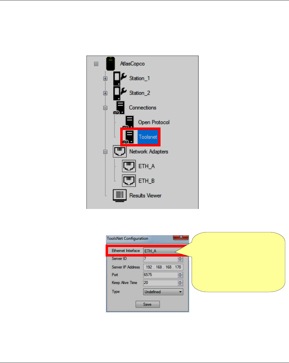
Focus 60 / Focus 61 User Guide Working with ToolsNet
9839 0211 01 Edition 1.1 99 (106)
12 WORKING WITH ToolsNet
ToolsNet is an application that configures the Focus 60 / Focus 61, in order to allow to send data to the
same ToolsNet.
To enable this application, double-click the ToolsNet icon placed in the Device Files area (refer to the
screen above: Connections section); the following pop-up shows:
After setting the ToolsNet Configuration, click Save.
Ethernet Interface has 3
options:
- None: It disables the
comunication
- ETH_A/B: Interface to use
to communicate with
ToosNet

CBP Focus 60 / Focus 61 User Guide
100 (106) 9839 0211 01 Edition 1.1
13 CBP
The CBP is a basic output protocol for tightening results. The default output port is 10001 on Ethernet
interface A (1.2). Each dataset contains detailed information about the tightening according to the data
output format listed in the table below:
Ser. No.
Focus
Ser. No.
Wrench
Data-
Set-Type
Focus
Counter
Station
Group
MWR
type
Date /
Time
MWR
Counter
Tightening
Strategy
Tightening
Status
Tightening
Status Code
MWR
Status
A76000441
A8370022A
f0
200
0
52
08.09.2016
11:13:18
214
M0
OK
0
160
A76000441
A8370022A
f0
201
0
52
08.09.2016
11:13:21
215
M0
OK
0
161
A76000441
A8370022A
f0
202
0
52
08.09.2016
11:13:23
216
M0
LCK
4000
160
IDN1
IDN2
IDN3
SeqID / JobID /
JobstepID /
PSET ID
Sequence
OK
Sequence
NOK
Target
OK
max
NOK
Sequence
Step
Unit
Snug
Point
Final
Torque
Station1
NewJob
2x25Nm
1001010000
1
0
2
2
1
Nm
15.00
22.29
Station1
NewJob
2x25Nm
1001010000
2
0
2
2
2
Nm
15.00
22.71
-
-
-
1010000
0
0
0
0
0
Nm
15.00
22.40
Click
Torque
Min.
Torque
Max.
Torque
Final
Angle
Click
Angle
Min.
Angle
Max.
Angle
tightening
time
Max. Tightening
Time
Station
Name
Group ID
PSET Name
20.76
15.00
80.00
3.12
2.36
0.00
360.00
0.5
15
Station1
GRP0
PSET0
21.18
15.00
80.00
8.07
6.52
0.00
360.00
0.5
15
Station1
GRP0
PSET0
42542
15.00
80.00
7.59
7.00
0.00
360.00
0.5
15
Station1
GRP0
PSET0
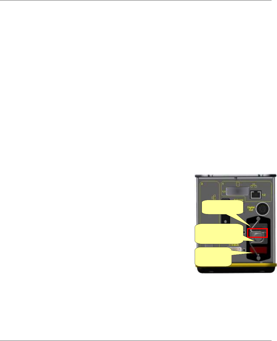
Focus 60 / Focus 61 User Guide Maintenance
9839 0211 01 Edition 1.1 101 (106)
14 MAINTENANCE
14.1 Focus 60 / Focus 61 Cleaning
Keep the Focus 60 / Focus 61 clean.
After use, remove any traces of oil, grease and dust from the Focus 60 / Focus 61, especially from the
user interfaces (for further details about the user interfaces, refer to the chapter “User Interfaces”).
Use an anti-static cleaning cloth in order to remove dust from the Focus 60 / Focus 61.
Avoid using harsh detergents to clean Focus 60 / Focus 61.
When the Ethernet cable(s) is not connected with the Focus 60 / Focus 61, insert the plug into the
respective housing(s) in order to protect itself from the dust.
When the SD Card(s) is not inserted into the Focus 60 / Focus 61, insert the plug into the respective
housing(s) in order to protect itself from the dust.
Keep always the connectors and the Serial Port RS232 clean, placed on the bottom side of the Focus 60 /
Focus 61.
14.2 Fuses Replacement
Two Miniature Fuses (5 x 20 mm, Time-Lag T, L, 250 VAC) are installed
into the Focus 60 / Focus 61.
The Fuses Holder (with the multifunctional power socket and the On-Off
switch) is placed on the bottom side of the Focus 60 / Focus 61.
If an overheating occurs on the Focus 60 / Focus 61 or if the On-Off
switch is not red lighted when the Focus 60 / Focus 61 is on, it is highly
recommended to replace the Miniature Fuses.
Do the following procedure in order to replace the two Miniature Fuses:
1. If necessary, switch the Focus 60 / Focus 61 off by acting on the On-
Off switch placed on the bottom side of the device (refer to the figure
on the right).
2. Disconnect the power cable from the AC Power in order to work in safe.
3. Disconnect the power cable from the multifunctional power socket (refer to the figure above).
Fuses Holder
Multifunctional
power socket
On-Off
switch
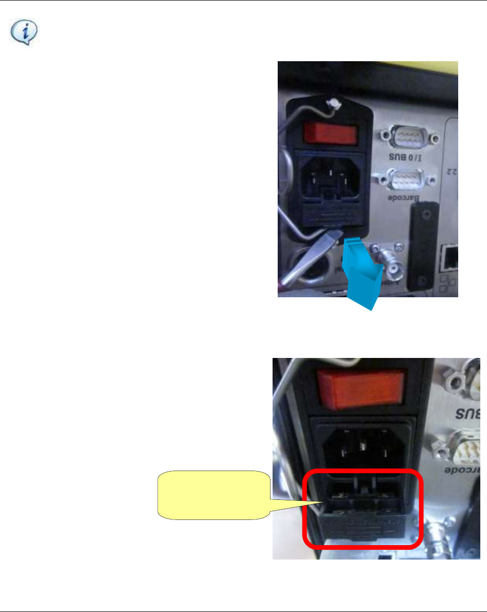
Maintenance Focus 60 / Focus 61 User Guide
102 (106) 9839 0211 01 Edition 1.1
NOTE: Pay close attention during the execution of the next steps: the two Miniature Fuses
could fall down on the floor. This is due to the fact that it is not necessary to remove the
Focus 60 / Focus 61 from its working position.
4. By using a shaped tool (i.e. screwdriver), extract the
Fuses Holder as shown in the picture on the right:
5. After extracting the Fuses Holder, it is possible to
see the two Miniature Fuses (refer to the picture on
the right).
Remove the old Miniature Fuses and install the new
ones.
Remove the old
Miniature Fuses and
install the new ones
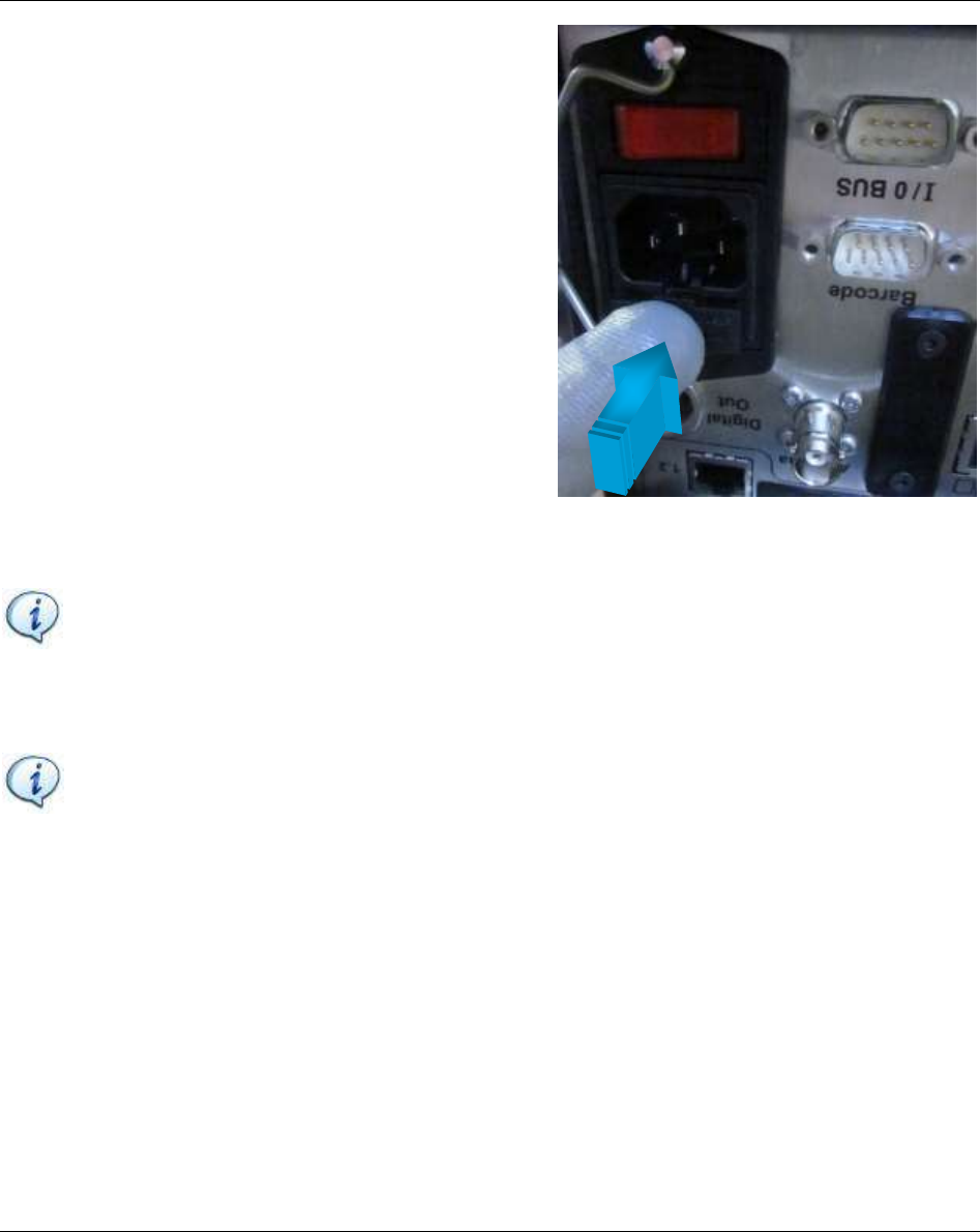
Focus 60 / Focus 61 User Guide Maintenance
9839 0211 01 Edition 1.1 103 (106)
6. After installing the new Miniature Fuses, push the
Fuses Holder into its housing as shown in the picture
on the right:
NOTE: Use ONLY the power cable provided with the Focus 60 / Focus 61 package. If you use
any other power cable, the protection provided by the equipment may be impaired.
7. Reconnect the power cable to the multifunctional power socket
8. Reconnect the power cable to the AC Power.
NOTE: Switch the Focus 60/ Focus 61 on, to verify that fuses replacement was done
correctly. Check, that the light of the On-Off switch is red and if the other LEDs (on the front
panel) illuminate correctly.

Troubleshooting Guide Focus 60 / Focus 61 User Guide
104 (106) 9839 0211 01 Edition 1.1
15 TROUBLESHOOTING GUIDE
Here is a quick troubleshooting guide for the Focus 60 / Focus 61.
If a problem occurs, before taking any action (replacing parts or contacting customer support), be sure to
check that the Focus 60 / Focus 61 was used correctly.
Improper operation can cause troubles even if the system is in good working order.
In case of issues, the log file (refer to paragraph “Enabling LOG Viewer” for further information) can
provide information about the problem.

Index Focus 60 / Focus 61
User Guide
9839 0211 01
2017-01
Edition 1.1
www.atlascopco.com