Atlas Polar 60068201 914MHz Transceiver Module User Manual
Atlas Polar Company Limited 914MHz Transceiver Module
User Manual

1 RADIO TRANSCEIVER MANUAL
SECTION 1
RADIO TRANSCEIVER
MANUAL
FOR INTERNAL USE ONLY
POLAR REMOTE CONTROLS PART NUMBER 600-682-01
DIVISION OF ATLAS POLAR COMPANY LTD. REV. #0
60 NORTHLINE RD. APRIL 2012
TORONTO ONTARIO M4B 3E5
2 RADIO TRANSCEIVER MANUAL
SECTION 1
TABLE OF CONTENTS
SECTION 1 INTRODUCTION
SECTION 2 TECHNICAL DATA
SECTION 3 OPERATION THEORY
SECTION 4 ELECTRICAL INTERFACE

1 RADIO TRANSCEIVER MANUAL
SECTION 1
SECTION ONE
INTRODUCTION

2 RADIO TRANSCEIVER MANUAL
SECTION 1
Please note:
This manual will only discuss the conditions governing regulations,
not the overall system. To understand the complete unit package, installation, operation
and maintenance, ALL equipment manuals should be read thoroughly.
POLAR RADIO REMOTE SYSTEM
This device complies with Part 15 of FCC & RSS-Gen of IC rules. Operation is
subject to the following two conditions: (1) This device may not cause harmful
interference, and (2) This device must accept any interference received,
including interference that may cause undesired operation.
Le present appareil est conforme aux CNR d’Industrie Canada applicable aux
appareils radio exempts de licence. L’exploitation est autorisée aux deux
conditions suivantes: (1) l’appareil ne doit pas produire de brouillage, et (2)
l’utilisateur de l’appareil doit accepter tout brouillage radioélectrique subi, même
si le brouillage est susceptible d’en compromettre le fonctionnement.
CAUTION : Changes or modifications not expressly approved by Atlas polar
Company Ltd., could void the users authority to operate this equipment.
NOTE: This equipment has been tested and found to comply with the limits for a class
B digital device, pursuant to Part 15 of the FCC rules. These limits are designed to
provide reasonable protection against harmful interference in a residential installation.
This equipment generates, uses and can radiate radio frequency energy and, if not
installed and used in accordance with the instructions, may cause harmful interference
to radio communications. However, there is no guarantee that interference will not
occur in a particular installation. If this equipment does cause harmful interference to
radio or television reception, which can be determined by turning the equipment off and
on, the user is encouraged to try to correct the interference by one or more of the
following measures:
-Reorient or relocate the receiving antenna.
-Increase the separation between the equipment and receiver.
-Connect the equipment into an outlet on a circuit different from that to which the
receiver is connected.
-Consult the dealer or manufacturer for further assistance.
RSS-Gen Notices for Transmitter Antenna
Under Industry Canada regulations, this radio transmitter may only operate using an
antenna of a type and maximum (or lesser) gain approved for the transmitter by Industry
Canada. To reduce potential radio interference to other users, the antenna type and its
3 RADIO TRANSCEIVER MANUAL
SECTION 1
gain should be so chosen that the equivalent isotropically radiated power (e.i.r.p.) is not
more than that necessary for successful communication.
This radio transmitter (IC: 6272A-60068201) has been approved by Industry Canada to
operate with the antenna types listed in this document with the maximum permissible
gain and required antenna impedance for each antenna type indicated. Antenna types
not included in this document, having a gain greater than the maximum gain indicted for
that type, are strictly prohibited for use with this device.
Conformément à la réglementation d’Industrie Canada, le présent émetteur radio peut
fonctionner avec une antenne d’une type et d’un gain maximal (ou inferieur) approuvé
pour l’émetteur par Industire Canada. Dans le but de réduire les risques de brouillage
radioélectrique à l’intention des autres utilisateurs, il faut choisir le type d’antenne et son
gain de sorte que la puissance istrope rayonnée équivalente (p.i.r.e.) ne dépasse pas
l’intensité nécessaire à l’établissement d’une communication satisfaisante.
Le présent émetteur radio (IC: 6272A-6006820) a été approuvé par Industrie Canada
pur fonctionner avec les types d’antenne énumérés ci-dessous et ayant un gain
admissible maximal et l’impédance requise pour chaque type d’antenne. Les types
d’antenne non inclus dans cette liste, ou dont le gain est supérieur au gain maximal
indiqué, sont strictement interdits pour l’exploitation de l’émetteur.

1 RADIO TRANSCEIVER MANUAL
SECTION 2
SECTION TWO
TECHNICAL DATA
2 RADIO TRANSCEIVER MANUAL
SECTION 2
ATLAS POLAR COMPANY LIMITED
POLAR 9900R TECHNICAL DATA
SYSTEM
Frequency: 902-924 MHz Frequency Hopping Spread Spectrum
Operating Temperature -25C to +50C
Transmission Range 122 m or 400 feet
Data Transmission 11 bytes including Identity and CRC error values
Addressing Programmable. 65,500 unique addresses
Approved by Pending
Operating Licensing Not required

1 RADIO TRANSCEIVER MANUAL
SECTION 3
SECTION THREE
OPERATION THEORY
2 RADIO TRANSCEIVER MANUAL
SECTION 3
OPERATION THEORY
The Polar Radio Remote Control System consists of a wireless transceiver that is
connected to the Polar actuator (purchased separately). All communicated information
between the transceiver is in a digital format and works on the 900 MHz frequency.
FREQUENCY HOPPING DESCRIPTION
The transceiver use 50 equally spaced frequencies (902 TO 928 MHz). The transceiver
has a stored unique random stepping sequence throughout the 50 channels. The
random stepping sequence will utilize all 50 channels, and continue to repeat the same
sequence during its communication. The transmitter and receiver portion of the
transceiver have identical bandwidth for the channel. The hopping system doesn’t use
any intelligence or coordinate with any other FHSS system operating in vicinity in any
way and its algorithm doesn’t change its hopping sequence to avoid any collision, hence
the system complies with the non-coordination requirement stated by FCC & IC.
The transceiver communicates on a frequency hopping, spread spectrum algorithm.
The hopping sequence is unique for each transceiver and therefore the communication
link is immune to interference from other radios. There is a setup procedure that is
required to establish the hopping sequence between the transceiver. This allows the
ability of swapping transmitters, receivers, or programming multiple transmitters for use
with one receiver. Once the communication link between one transceiver is
established, another tuned transmitter cannot interfere unless the first link (other
transmitter) is disconnected.
The receiver has a safety algorithm to protect against undesirable interference. The
safety algorithm not only brings all functions to a neutral state but also closes the safety
dump valve, ensuring no unwanted movement of the crane.
The receiver must be powered up before the transmitter. When the transmitter is
powered, there will be a 1 second delay before communication. This is to allow
transceiver to synchronization.
When the communication task is completed, the transmitter should be turned off with
the
E-stop engaged to preserve battery power. If the communication has been stopped due
to pressing of an E-Stop, powering down, or loss of range, the communication may be
resumed by cycling the E-stop.
3 RADIO TRANSCEIVER MANUAL
SECTION 3

1
RADIO TRANSCEIVER MANUAL
SECTION 4
SECTION FOUR
ELECTRICAL INTERFACE

2
RADIO TRANSCEIVER MANUAL
SECTION 4
ELECTRICAL INTERFACE
1. Connectors:
Connector J1
Pin description
Pin 1
Serial Instruction Enable
Pin 2
Serial Instruction Clock
Pin 3
Data Rx
Pin 4
Data Tx
Pin 5
Read/Write Data Message
Pin 6
Read/Write Serial Instruction
Pin 7
Serial Instruction Data
Pin 8
Supply Voltage
Connector J2
Pin description
Pin 1
Ground
Pin 2
Ground
Pin 3
Ground
Connector J3
Pin description
Pin 1
Ground
Pin 2
Ground
Pin 3
Ground
Connector J4
Pin description
Pin 1
Ground
Pin 2
Ground
Pin 3
Ground
Connector J5
Pin description
Pin 1
Ground
Pin 2
Ground
Pin 3
Ground
Connector J6
Pin description
Pin 1
IR Transmit
Pin 2
IR Receive
Pin 3
Not used
Pin 3
IR Shut down

3
RADIO TRANSCEIVER MANUAL
SECTION 4
2. DC Characteristics:
Parameter
Min
Typ
Max
Unit
Comment
Supply Voltage
3.5
5
6.5
Volts
Voltage to any Serial
Instruction line
3.5
5
6.5
Volts
Should not
exceed supply
voltage
Data Tx voltage
3.5
5
6.5
Volts
Should not
exceed supply
voltage
Data Rx voltage
Vcc
Tx/Rx data rate
9.6k
19.2k
20k
Bits/second
3. Carrier Frequency, Frequency deviation and hopping sequence Selection:
The register values for the carrier frequency, of the receiver, high and low deviation carrier
frequency for transmitter registers and hopping patterns are found in the arrays contained in the
files “RF_Tables.C”. These tables must be included in the mother board operating code to load
the values into the RF module. Below is a list of the function calls and a brief description of the
function and variables that are required.
Function call
Description
void Next_channel(void)
Loads a hopping channel index from
the random table
void Take_Reg_TX(int NbChannel)
Loads the transmitter register
frequency values (carrier plus deviation
and carrier minus deviation) with the
hopping channel value
void Take_Reg_RX(int NbChannel)
Loads the receiver register frequency
values with the receiver hopping
channel value.
The communication of the register values to the RF module must comply with the timing as
indicated in the AT86RF211S data sheet.
Once these registers are loaded with the parameter values, the Data Tx and/or Data Rx can be
read or written directly as a data stream to the Data Tx, Data Rx pins. The mother board must
supply the data buffering.
The serial number entered into the ROM memory of the mother board provides an index to the
random table so there will be a hopping pattern uniqueness to the transmitter/receiver pair if
they contain the same serial number. The serial number also must become part of the packet
for data identification. The data packet must also include a CRC value for data verification.
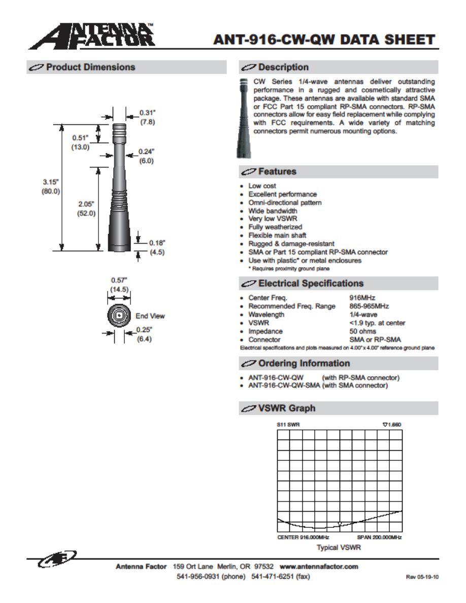
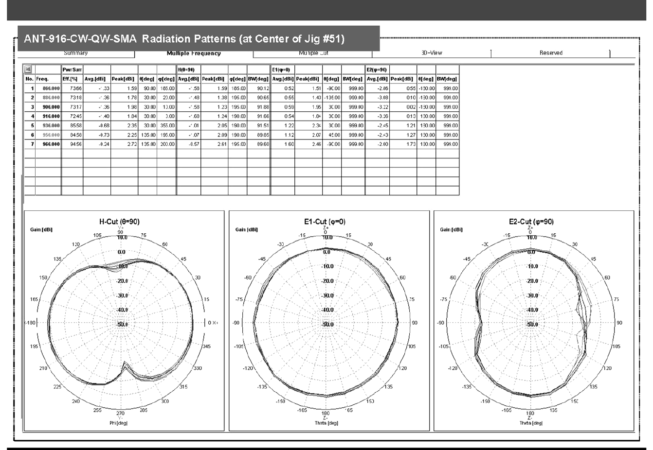
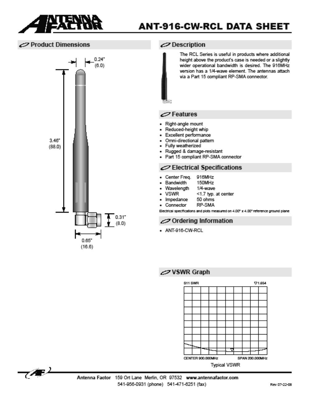
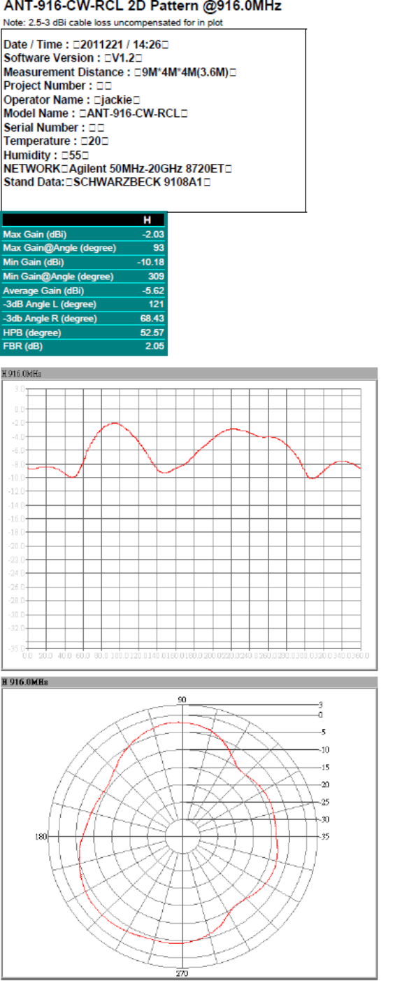
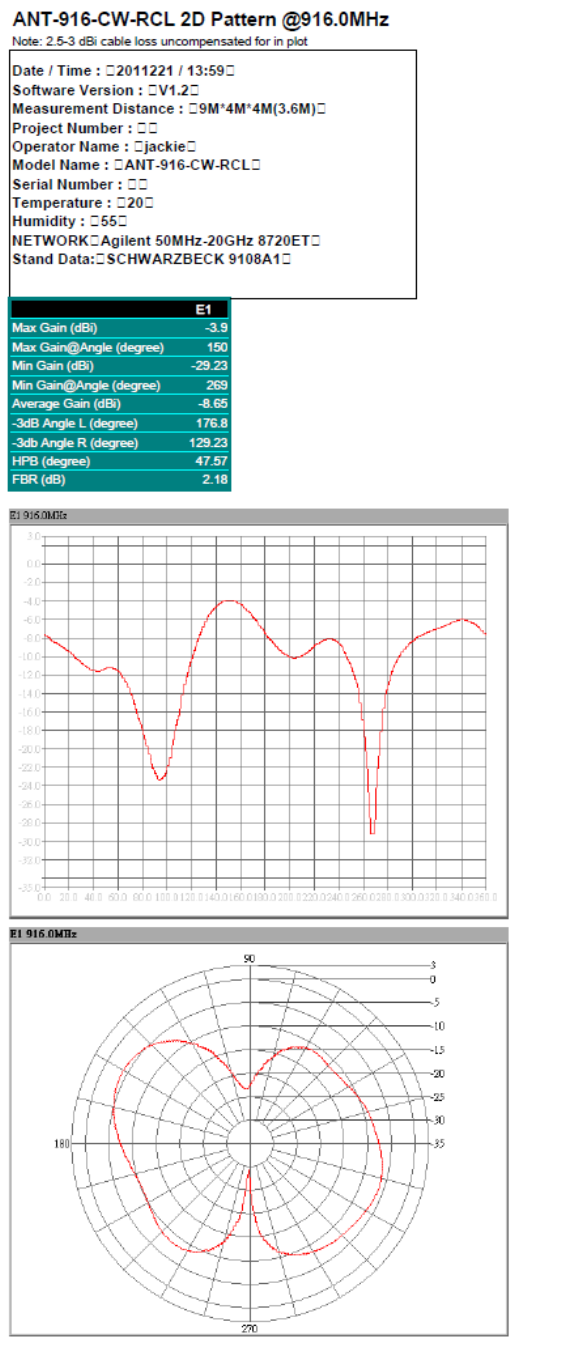
4. Antenna:
The only antennas that are permitted for use with the 600-682-01 RF module are the Antenna
Factor ANT-916-CW-QW, Antenna Factor ANT-916-CW-RCL, and a 3.0” solid wire.
4
RADIO TRANSCEIVER MANUAL
SECTION 4
4 RADIO TRANSCEIVER MANUAL
SECTION 4
RADIO TRANSCEIVER MANUAL
SECTION 4
6
RADIO TRANSCEIVER MANUAL
SECTION 4
7
RADIO TRANSCEIVER MANUAL
SECTION 4
8
RADIO TRANSCEIVER MANUAL
SECTION 4
9
RADIO TRANSCEIVER MANUAL
SECTION 4
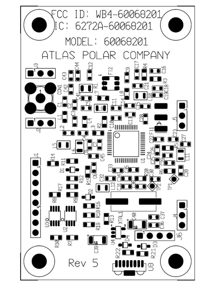
5. Required Host System Labeling
FCC ID and Industry Canada ID on Host System
The integrator must affix the module’s FCC ID and Industry Canada ID on the product, if
the part number 600-682-01 is installed inside the host system and its FCC ID and
Industry Canada ID may not be visible, then the FCC ID and Industry Canada ID label
must appear on the outside of the host system visible to the user.
Example text to appear somewhere on the outside of the host system visible to the end
user:
Contains “FCC ID: WB4-60068201” & :IC: “6272A-60068201”
OR
Contains Transmitter Module, FCC ID: WB4-60068201 IC: 6272A-60068201
6. To access the RF module remove all screws on the enclosure and
separate/open enclosure.
7. Module currently used in the following Atlas Polar Products :
MODEL PB926-T
MODEL PB926-R
MODEL HV900-60H
MODEL HV900-60S