Atlas Air Compressor Users Manual ManualsLib Makes It Easy To Find Manuals Online!
2014-12-12
: Atlas Atlas-Air-Compressor-Users-Manual-118969 atlas-air-compressor-users-manual-118969 atlas pdf
Open the PDF directly: View PDF ![]() .
.
Page Count: 70

Instruction book
2920 1521 00 1
Atlas Copco Stationary Air Compressors
Instruction book
SF1 - SF2 - SF4 Skid -Tank-mounted
SF6 - SF8 Twin
SF6 - SF8 - SF11 - SF15 Multi
Copyright 2003, Atlas Copco Airpower n.v, Antwerp, Belgium.
Any unauthorized use or copying of the contents or any part thereof is prohibited. This applies in
particular to trademarks, model denominations, part numbers and drawings.
This instruction book meets the requirements for instructions specified by the machinery directive
98/37/EC and is valid for CE as well as non-CE labelled machines.
No. 2920 1521 00
Registration code: APC SF / 38 / 980
2003-10 www.atlascopco.com
Note: The PED instructions for this machine are included at the end of the book.

Instruction book
2920 1521 00 2
This instruction book describes how to handle the machines to ensure safe operation, optimum
efficiency and long service life.
Read this book before putting the machine into operation to ensure correct handling, operation
and proper maintenance from the beginning. The maintenance schedule comprises measures for
keeping the machine in good condition.
Keep the book available for the operator and make sure that the machine is operated and that
maintenance is carried out according to the instructions. Record all operating data, maintenance
performed, etc. in an operator's logbook available from Atlas Copco. Follow all relevant safety
precautions, including those mentioned on the cover of this book.
Repairs must be carried out by trained personnel from Atlas Copco who can be contacted for any
further information.
In all correspondence mention the type and the serial number, shown on the data plate.
For all data not mentioned in the text, see sections "Preventive maintenance schedule" and "Principal
data".
The company reserves the right to make changes without prior notice.

Instruction book
2920 1521 00 3
1 LEADING PARTICULARS................................................................................................................... 5
1.1 General description........................................................................................................................ 5
1.1.1 Compressor variants ............................................................................................................... 5
1.1.2 Compressor elements (Fig. 1.1).............................................................................................. 5
1.2 Air flow ........................................................................................................................................... 9
1.3 Cooling and condensate drain systems (Fig. 1.9) ......................................................................... 9
1.4 Regulating system on SF Skid - Tank-mounted - Twin ............................................................... 10
1.5 Regulating system on SF Multi .................................................................................................... 11
1.5.1 Controlling the compressor ................................................................................................... 11
1.5.2 Protecting the compressor .................................................................................................... 11
1.5.3 Monitoring components subject to service............................................................................ 11
1.5.4 Automatic restart after voltage failure ...................................................................................11
1.5.5 Control panel (Fig. 1.11) ....................................................................................................... 12
1.5.6 Display – keys ....................................................................................................................... 13
1.5.7 Function keys (5-Fig. 1.11) ................................................................................................... 13
1.6 Electric cabinet on SF Multi ......................................................................................................... 15
1.7 Air dryer on SF Full-Feature (Fig. 1.15)....................................................................................... 16
2 INSTALLATION ................................................................................................................................. 17
2.1 Dimension drawings (Figs. 2.1 up to 2.5) ....................................................................................17
2.2 Installation proposal (Fig. 2.6) ..................................................................................................... 22
2.3 Electrical connections .................................................................................................................. 24
2.4 Pictographs .................................................................................................................................. 27
3 OPERATING INSTRUCTIONS .......................................................................................................... 28
3.1 Initial start-up ............................................................................................................................... 28
3.2 Starting......................................................................................................................................... 28
3.2.1 Multi....................................................................................................................................... 28
3.2.2 Skid - Tank-mounted - Twin .................................................................................................. 28
3.3 During operation .......................................................................................................................... 29
3.3.1 Multi....................................................................................................................................... 29
3.3.2 Skid - Tank-mounted - Twin .................................................................................................. 29
3.4 Stopping....................................................................................................................................... 29
3.4.1 Multi....................................................................................................................................... 29
3.4.2 Skid - Tank-mounted - Twin .................................................................................................. 29
3.5 Taking out of operation at end of compressor service life........................................................... 29
4 MAINTENANCE ................................................................................................................................. 30
4.1 Compressor drive motors ............................................................................................................ 30
4.2 Preventive maintenance schedule for the compressor................................................................ 30
5 ADJUSTMENTS AND SERVICING PROCEDURES ........................................................................ 32
5.1 Air filter (1-Figs. 1.7/1.8) .............................................................................................................. 32
5.2 Belt exchange/tensioning (Fig. 5.1) ............................................................................................. 32
5.3 Coolers......................................................................................................................................... 32
5.4 Safety valve ................................................................................................................................. 33
6 PROBLEM SOLVING ........................................................................................................................ 34
7 PRINCIPAL DATA ............................................................................................................................. 35
7.1 Electric cable size for SF1-8 ........................................................................................................ 35
7.2 Electric cable size for SF 6-15 Multi ............................................................................................ 35
7.3 Overload relays for SF1-8............................................................................................................ 36
7.4 Overload relays for SF6-15 Multi ................................................................................................. 36
7.5 Main fuses for SF1-8.................................................................................................................... 37
7.6 Main fuses for SF6-15 Multi......................................................................................................... 37
7.7 Reference conditions/limitations .................................................................................................. 37
7.8 SF1-4 8bar 50 Hz 1) ................................................................................................................... 38
7.9 SF2-4 10 bar 50 Hz 1) ................................................................................................................ 38
7.10 SF1-4 100 psi 60 Hz 1)............................................................................................................. 38
7.11 SF2-4 145 psi 60 Hz 1)............................................................................................................. 38
7.12 SF6-15 Multi 8 bar 50 Hz 1)...................................................................................................... 39
7.13 SF6-15 Multi 10 bar 50 Hz 1).................................................................................................... 39
7.14 SF6-15 Multi 100 psi 60 Hz 1) .................................................................................................. 39
7.15 SF6-15 Multi 125 psi 60 Hz 1) .................................................................................................. 40

Instruction book
2920 1521 00 4
7.16 SF6-15 Multi 145 psi 60 Hz 1) .................................................................................................. 40
8 REGULATOR FUNCTIONS FOR SF MULTI .................................................................................... 41
8.1 Menu-driven control programs..................................................................................................... 41
8.1.1 Function of control programs ................................................................................................ 42
8.1.2 Main screen........................................................................................................................... 42
8.1.3 Calling up other menus ......................................................................................................... 44
8.2 Quick look at actual compressor status....................................................................................... 44
8.3 Status data menu......................................................................................................................... 45
8.3.1 No message exists ................................................................................................................ 45
8.3.2 A shut-down message exists ................................................................................................45
8.3.3 A warning message exists .................................................................................................... 46
8.3.4 A service warning message exists ........................................................................................ 47
8.4 Measured data menu................................................................................................................... 47
8.5 Counters menu ............................................................................................................................ 48
8.6 Test menu .................................................................................................................................... 48
8.7 Modify parameters menu ............................................................................................................. 49
8.8 Modifying parameters .................................................................................................................. 49
8.8.1 Modifying the pressure bands ............................................................................................... 50
8.9 Modifying protection settings ....................................................................................................... 51
8.9.1 Checking protections for compressor modules..................................................................... 51
8.9.2 Modifying protections for Dryer LAT on Full-Feature machines ........................................... 52
8.10 Modifying service plans ............................................................................................................. 52
8.11 Programming Clock function...................................................................................................... 54
8.11.1 Programming start/stop/pressure band commands ............................................................ 54
8.11.2 To activate/deactivate the timer .......................................................................................... 56
8.11.3 To modify a command......................................................................................................... 56
8.11.4 To add a command ............................................................................................................. 57
8.11.5 To delete commands........................................................................................................... 58
8.12 Configuration menu.................................................................................................................... 59
8.12.1 Programming compressor control modes ........................................................................... 60
8.13 Service menu ............................................................................................................................. 60
8.14 Saved data menu....................................................................................................................... 63
8.15 Programmable settings.............................................................................................................. 64
8.15.1 Regulation settings.............................................................................................................. 64
8.15.2 Service settings ................................................................................................................... 65
9 CONVERSION LIST OF SI UNITS INTO US/BRITISH UNITS ......................................................... 65
Instruction book
2920 1521 00 5
1 LEADING PARTICULARS
1.1 General description
SF1 up to SF15 are stationary, oil-free compressors driven by an electric motor.
1.1.1 Compressor variants
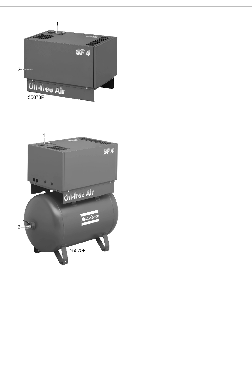
SF Skid (Fig. 1.2)
The components of the compressor are housed in a bodywork with removable front/top panel. The
compressor is mounted on a frame designed to allow easy installation at the required spot.
SF Tank-mounted (Fig. 1.3)
The components of the compressor are housed in a bodywork with removable front/top panel. The
compressor is mounted on an air receiver.
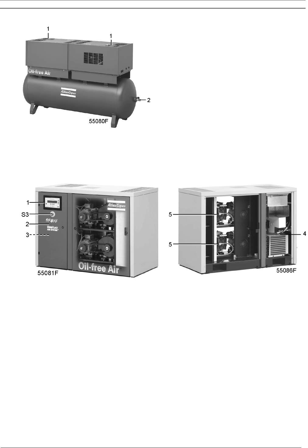
SF Twin (Fig. 1.4)
Two compressor modules are mounted on an air receiver. Each module is provided with its own control
panel.
SF Multi Pack
The compressors have two up to four compressor modules enclosed in a sound-insulated bodywork.
The front door comprises an Elektronikon regulator including the start and stop buttons. An
emergency stop button is also provided. An electric cabinet comprising the motor starter is installed
behind the front door.
SF Multi Full-Feature (Figs. 1.5 and 1.6)
Full-Feature compressors are Pack compressors additionally provided with an air dryer integrated in
the bodywork. The dryer removes moisture from compressed air by cooling the air to near freezing
point and automatically draining the condensate. See section 1.7.
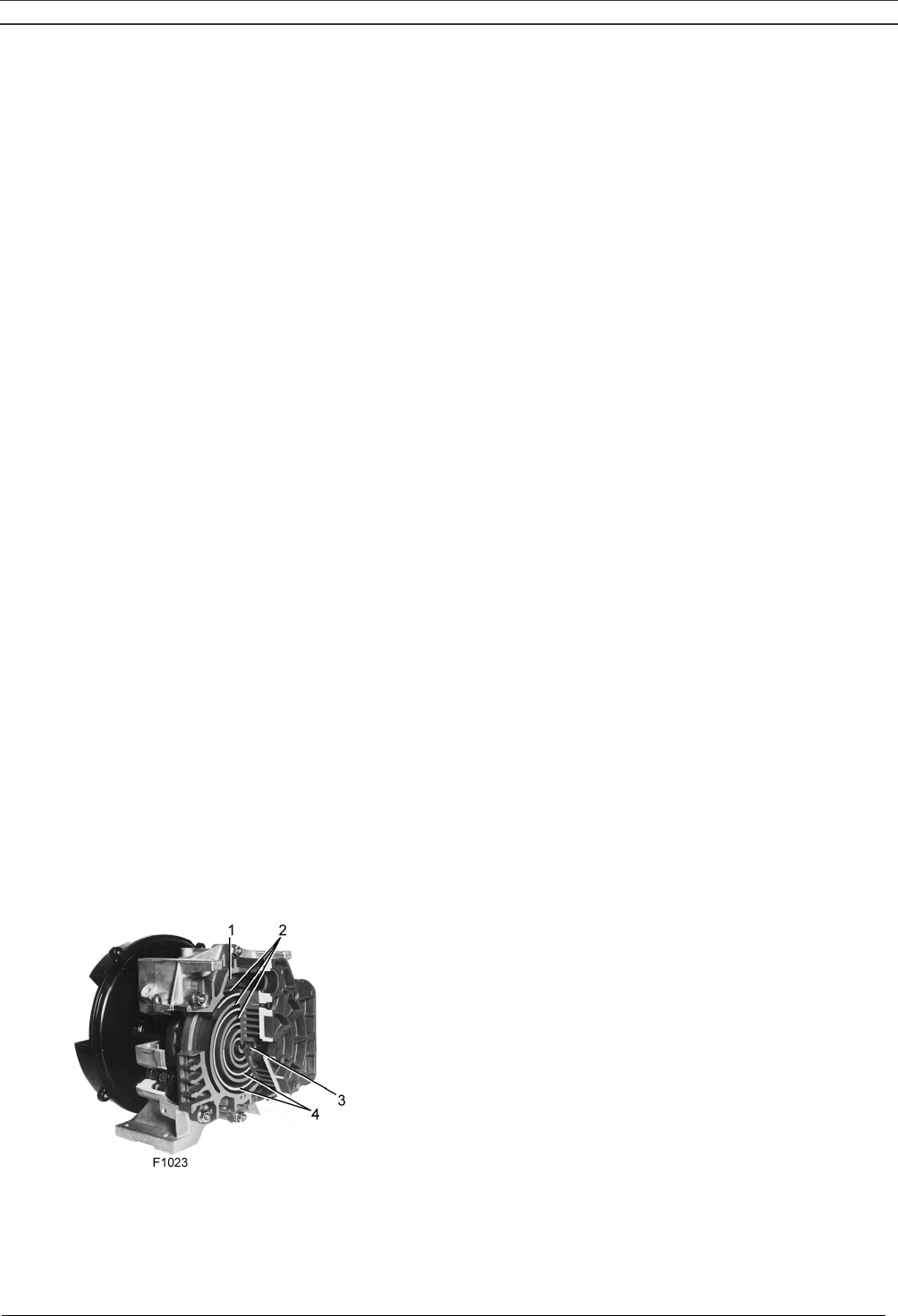
1.1.2 Compressor elements (Fig. 1.1)
Each compressor element consists of a fixed scroll-shaped housing and a scroll-shaped rotor. Air
enters the compressor element through inlet opening (1). Once the air is drawn in, the orbiting scroll
(4) seals the inlet opening and forces the air into a continuously decreasing space. As scroll (4) keeps
orbiting, this process of compression is constantly repeated, resulting in discharging of oil-free
compressed air through outlet opening (3).
1 Air inlet
2 Fixed scroll
3 Compressed air outlet
4 Orbiting scroll
Fig. 1.1 Compressor element
Instruction book
2920 1521 00 6
1 Control panel
2 Air outlet valve
Fig. 1.2 SF4 Skid
1 Control panel
2 Air outlet valve
1.3 SF4 Tank-mounted
Instruction book
2920 1521 00 7
1 Control panels
2 Air outlet valve
Fig. 1.4 SF Twin
1 Elektronikon regulator
2 Electric cabinet
3 Air outlet valve
4 Dryer (on Full-Feature)
5 Compressor modules
S3 Emergency stop button
Fig. 1.5 SF8FF Multi
Instruction book
2920 1521 00 8
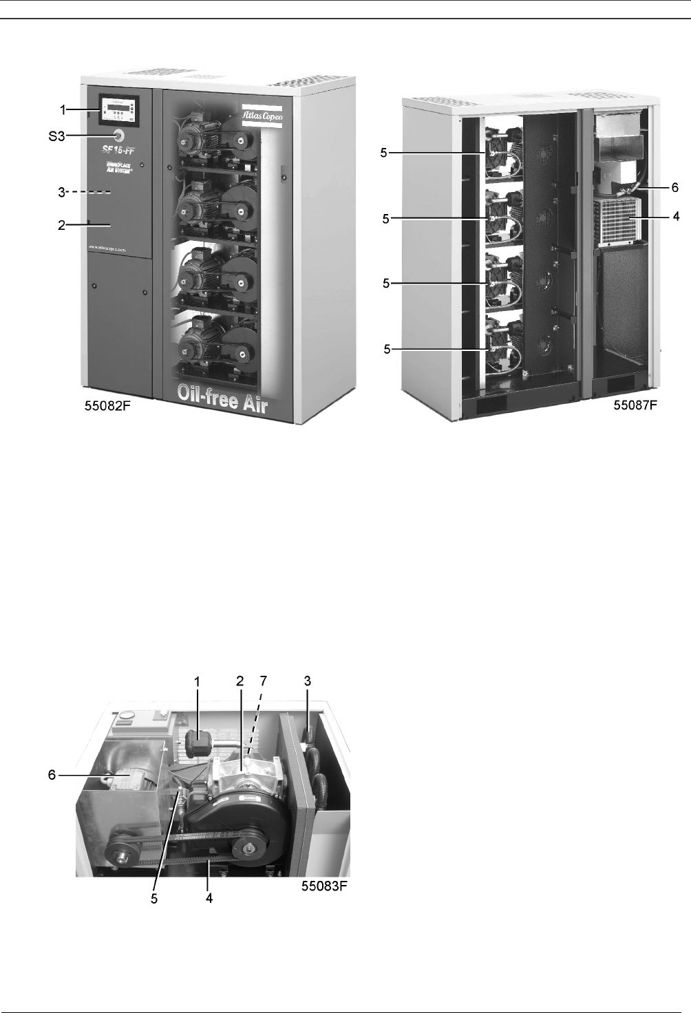
1 Elektronikon regulator
2 Electric cabinet
3 Air outlet valve
4 Dryer (on Full-Feature)
5 Compressor modules
6 Safety valve (ASME)
S3 Emergency stop button
Fig. 1.6 SF15FF Multi
1 Air filter
2 Compressor element
3 Air cooler
4 Belts
5 Safety valve
6 Drive motor
7 Safety valve
Fig. 1.7 Details of a compressor module on SF Tank-mounted
Instruction book
2920 1521 00 9
1 Air filter
2 Drive motor
3 Compressor element
4 Compressed air outlet
5 Safety valve (CE)
Fig. 1.8 Details of a compressor module on SF Multi
1.2 Air flow
Air is drawn through the air filter into the compressor modules and is compressed. Compressed air is
discharged through the check valve and air cooler towards the air net.
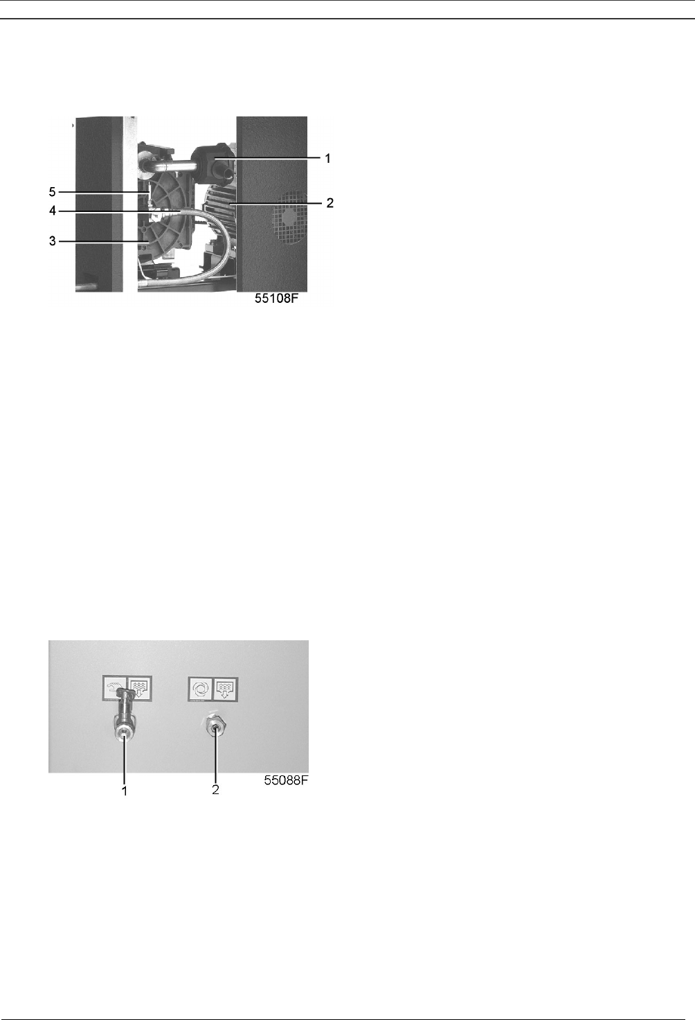
1.3 Cooling and condensate drain systems (Fig. 1.9)
Each compressor element is cooled by a fan. The fan is mounted on the drive shaft of the compressor
element. The cooling air is blown over the compressor element and air cooler via a duct.
For SF Multi two fans, driven by electric motors, expel warm air from the bodywork.
SF Multi have a condensate trap, with an automatic condensate outlet (2) and a manual drain valve
(1).
1 Manual condensate drain valve
2 Automatic condensate outlet
Fig. 1.9 Condensate drains on SF Multi
Instruction book
2920 1521 00 10
1.4 Regulating system on SF Skid - Tank-mounted - Twin
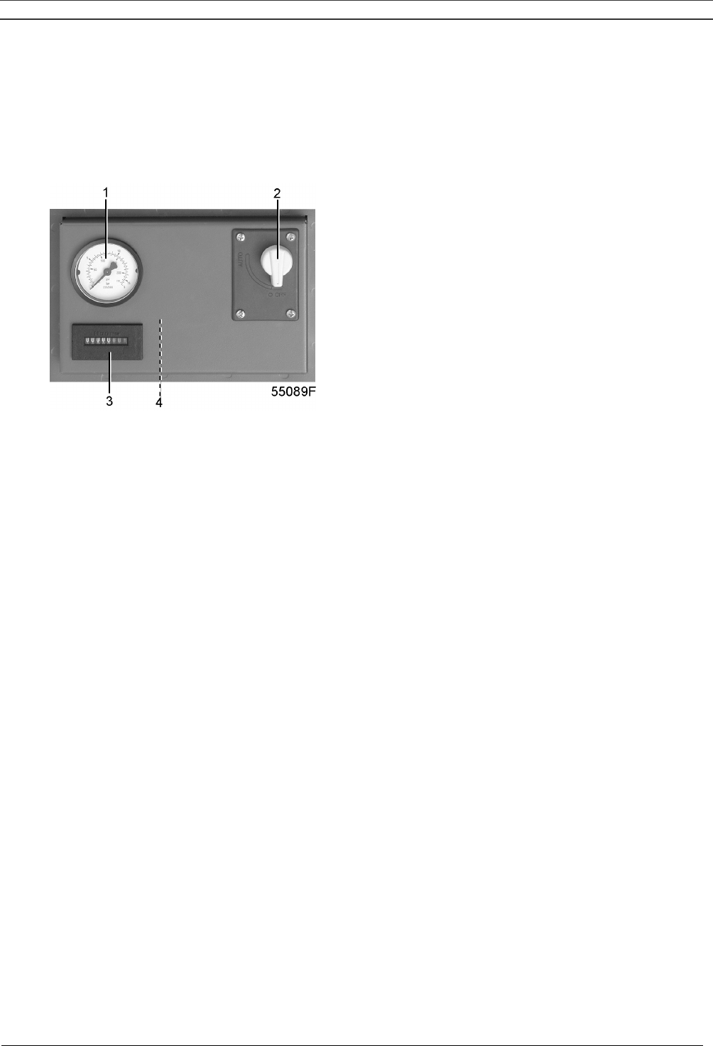
The air net pressure is kept within limits by a pressure switch mounted in the cabinet below the control
panel (Fig. 1.10). The switch is connected to the air outlet and electrically connected in the circuit of
the drive motor. The switch opens and closes its contacts at pre-set pressures.
1 Pressure gauge
2 On/off switch
3 Hourmeter
4 Air pressure switch/circuit breaker
Fig. 1.10 Control panel SF Skid - Tank-mounted - Twin
When the contacts are closed, the circuit to the drive motor is made: the compressor is operating. The
air output is maximum.
When the pressure reaches the pre-set maximum, the circuit to the drive motor is broken, causing the
compressor to stop. The air output is stopped.
Protecting the compressor
The compressor will be shut down in case temperature switch (TSHH11-Fig. 2.7) trips.
Warning
Before carrying out any inspection or repair, stop the compressor, switch off the voltage, open the
isolating switch and depressurize the compressor.

Instruction book
2920 1521 00 11
1.5 Regulating system on SF Multi
SF Multi are provided with an Elektronikon® regulator (Fig. 1.11) to control the compressor.
The following is a short description of the main functions of the regulator. Consult section 8 for a
detailed description of all functions.
1.5.1 Controlling the compressor
The Elektronikon regulator keeps the net pressure within programmable limits by starting and stopping
the compressor modules, depending on the air consumption. The regulator distributes the running
time among the compressor modules, taking into account the availability and number of running hours
of each compressor module.
When the compressor has stopped automatically and the net pressure decreases, the regulator will
start a compressor module before the net pressure has dropped to the starting pressure to prevent the
net pressure from falling under the programmed minimum level.
1.5.2 Protecting the compressor
If one or more compressor modules are shut down due to a protection function a warning message will
be shown on the display.
The compressor will be shut down in case temperature switch (TSHH20-Fig. 2.8) trips. See also
section 8.3.2.
Warning
Before carrying out any inspection or repair, stop the compressor, switch off the voltage, open the
isolating switch and depressurize the compressor.
After remedying, switch on the voltage and press the key “Reset” (F3).
1.5.3 Monitoring components subject to service
A number of service operations are grouped in plans (called Service plans I, A, B and D). Each
Service plan has a programmed time interval. If a time interval is exceeded, a message will appear on
the display to warn the operator to carry out the service actions belonging to that plan.
1.5.4 Automatic restart after voltage failure
The regulator has a built-in function to automatically restart the compressor if the voltage is restored
after voltage failure. For compressors leaving the factory, this function is made inactive. If desired,
the function can be activated. Consult Atlas Copco.
Instruction book
2920 1521 00 12
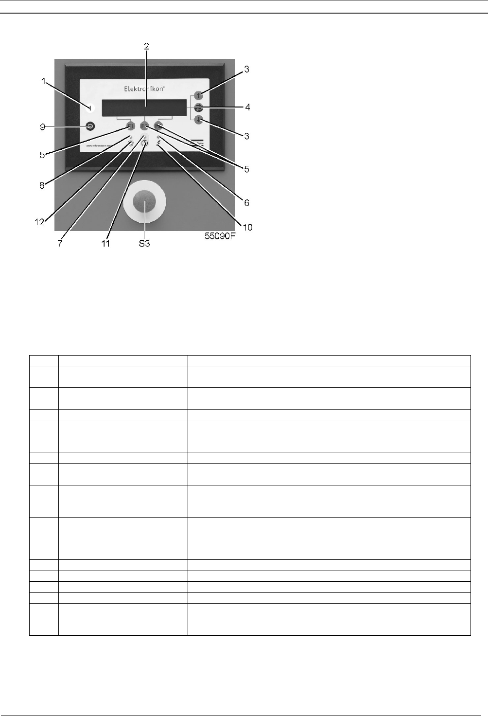
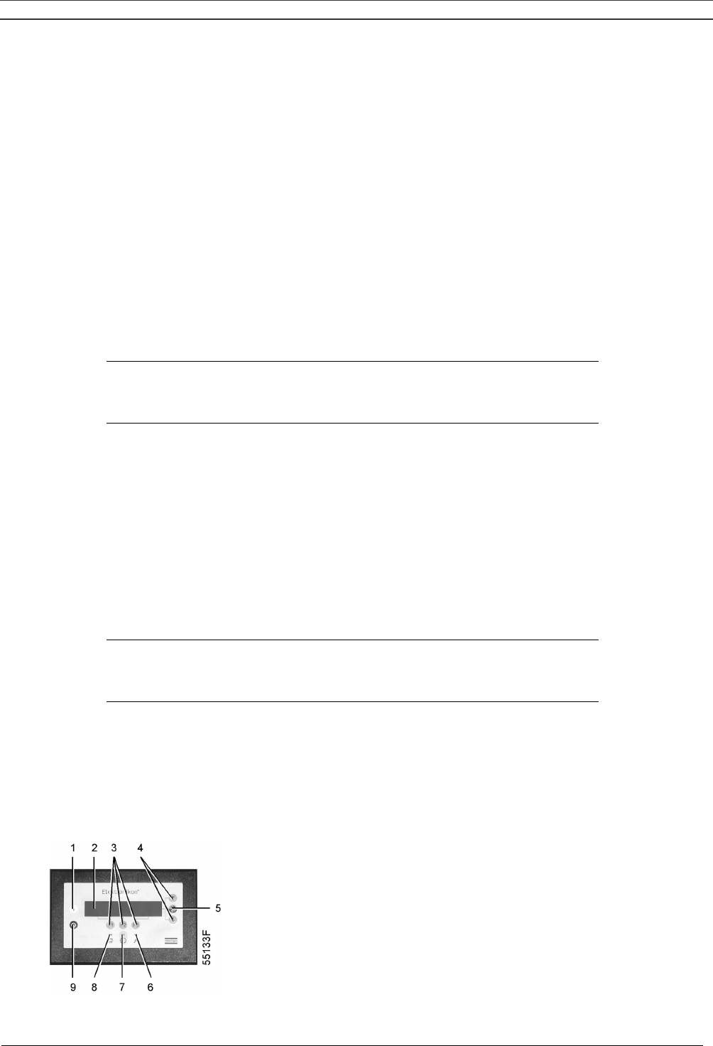
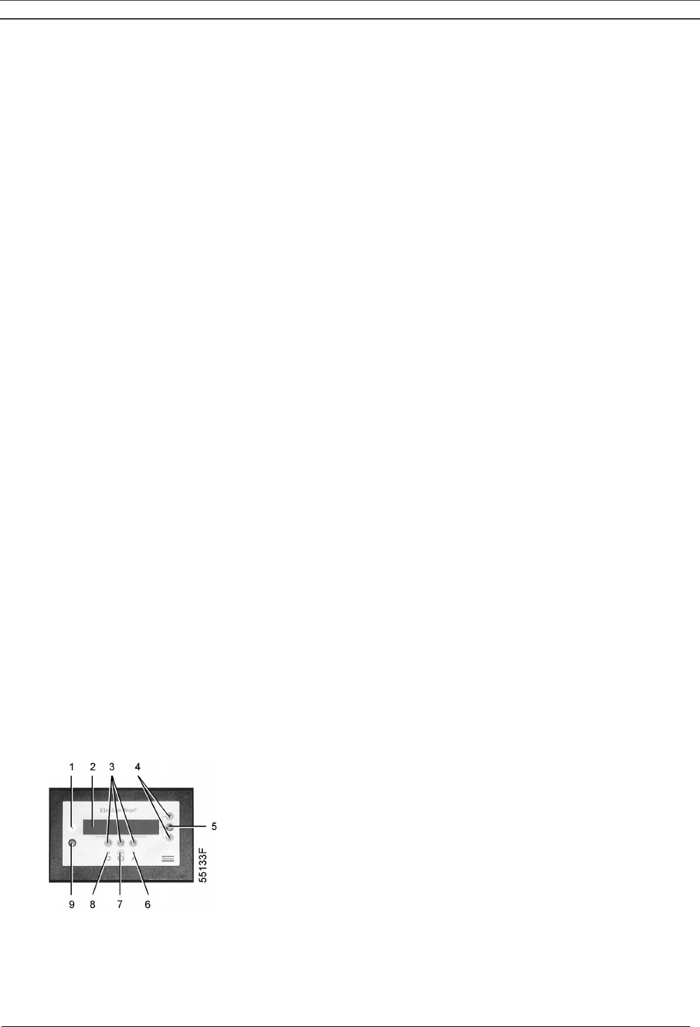
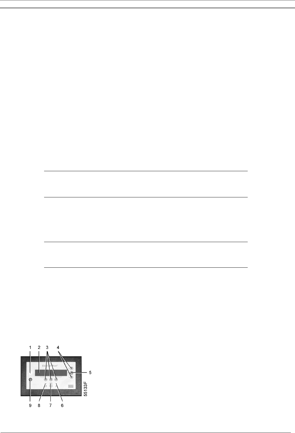
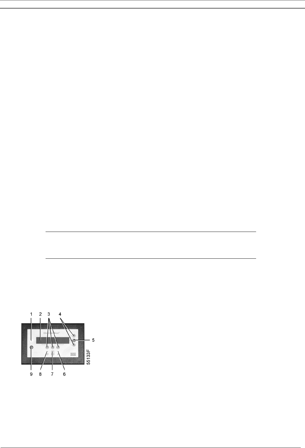
Fig. 1.11 Elektronikon regulator on SF Multi
1.5.5 Control panel (Fig. 1.11)
To control the compressor and to read and modify programmable parameters, the regulator is provided with a
control panel including:
Ref Designation Function
1 Start button Push button to start the compressor. LED (8) lights up indicating
that the regulator is operative (in automatic operation).
2 Display Indicates messages concerning the compressor operating
condition, a service need or a fault.
3 Scroll keys Keys to scroll through the display.
4 Tabulator key
Key to select the parameter indicated by a horizontal arrow.
Only the parameters followed by an arrow pointing to the right
are accessible for modifying.
5 Function keys Keys to control and program the compressor.
6 Voltage on LED Indicates that the voltage is switched on.
7 General alarm LED Is alight in case of a warning condition, see section 8.3.
7 General alarm LED
Blinks in case of shut-down condition, if a sensor with shut-
down function is out of order or after an emergency stop. See
section 8.3.
8 Automatic operation LED
Indicates that the regulator is automatically controlling the
compressor: the compressor is stopped and restarted
depending on the air consumption and the limitations
programmed in the regulator.
9 Stop button Push button to stop the compressor. LED (8) goes out.
10 Pictograph Voltage on.
11 Pictograph Alarm condition.
12 Pictograph Automatic operation.
S3 Emergency stop button
Push button to stop the compressor immediately in case of
emergency. After remedying the trouble, unlock the button by
pulling it out.
Instruction book
2920 1521 00 13
1.5.6 Display – keys
Compressor Outlet 7.0 bar
Compressor Running ↓
Menu - - - -
F1 F2 F3
Fig. 1.12 Typical example of a display
Operating condition of a compressor module
The symbols shown above key F3 indicate the operating condition of each control module, see also section
8.1.2:
Symbol Indicates
-
that the compressor module is available (ready to run), each
symbol stands for a compressor module (the left symbol stands for
the lowest mounted module, the right symbol stands for the
highest module)
▄ that the compressor module is running
- (blinking) that the compressor module is not available (due to minimum stop
time or too many starts)
* (blinking) that the compressor module is shut-down
Scroll keys (3-Fig. 1.11)
These keys, labelled with vertical arrows, allow to scroll through the display.
As long as a downwards pointing arrow is shown at the utmost right position of the display, the key (3) with
the same symbol can be used to see the next item.
As long as an upwards pointing arrow is shown at the utmost right position of the display, the key (3) with the
same symbol can be used to see the previous item.
Tabulator key (4-Fig. 1.11)
This key, labelled with two horizontal arrows, allows the operator to go to the next field of the display, e.g.
during modifying of programmable parameters.
1.5.7 Function keys (5-Fig. 1.11)
The keys are used:
- To call up or program settings
- To reset an active shut-down or service message, or an emergency stop
- To have access to all data collected by the regulator
The function keys allow to make the required selection from a menu of possibilities. The functions of the keys
vary depending on the displayed menu. The actual function is abbreviated and indicated on the bottom line of
the display just above the relevant key. Only the active and relevant functions at a moment are shown:
Designation Function
Back To return to a previously shown option or menu
Cancel To cancel a programmed setting when programming parameters
Delete To delete compressor start/stop commands
Extra To find the module configuration of the regulator
Help To find the Atlas Copco internet address
Limits To show limits for a programmable setting
Mainscreen To return from a menu to the main screen
Instruction book
2920 1521 00 14
Designation Function
Menu Starting from the main screen, to have access to submenus
Menu Starting from a submenu, to return to a previous menu
Modify To modify programmable settings
Program To program modified settings
Reset To reset a timer or message
Return To return to a previously shown option or menu
Selecting a menu
To facilitate controlling the compressor, menu-driven programs are implemented in the electronic module.
Use the function keys (5) to select the menus in order to program and monitor the compressor. See also
section 8.
Fig. 1.13 Menu flow, SF Multi
Instruction book
2920 1521 00 15
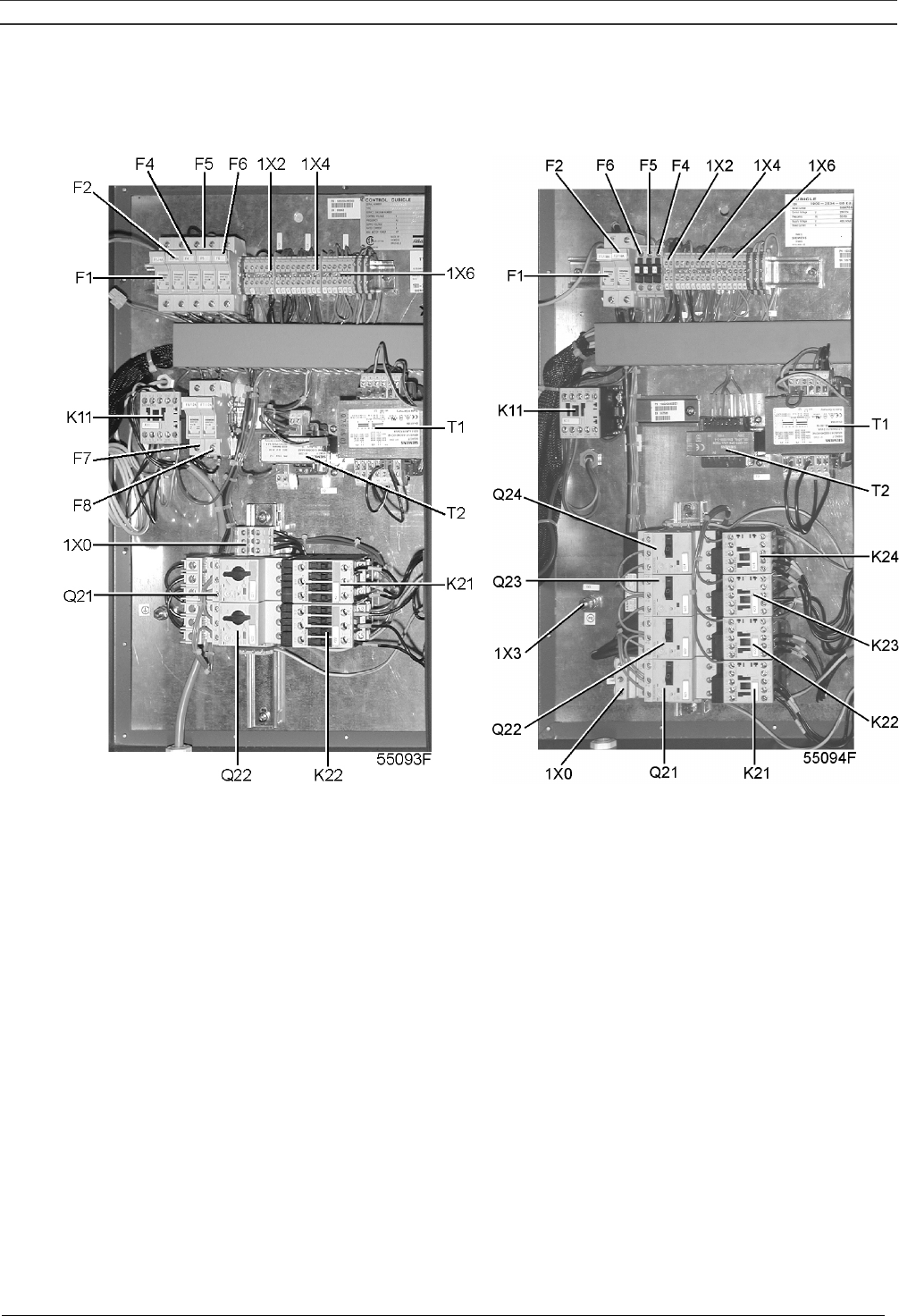
1.6 Electric cabinet on SF Multi
F1/8 Fuses
K11 Auxiliary contactor, dryer
K21/24 Contactors
Q21/24 Circuit breakers
T1/2 Transformers
1X0 Terminal strip, mains supply
1X2 Terminal strip, dryer
1X3/6 Terminal strips
Fig. 1.14 Electric cabinets, SF Multi
Instruction book
2920 1521 00 16
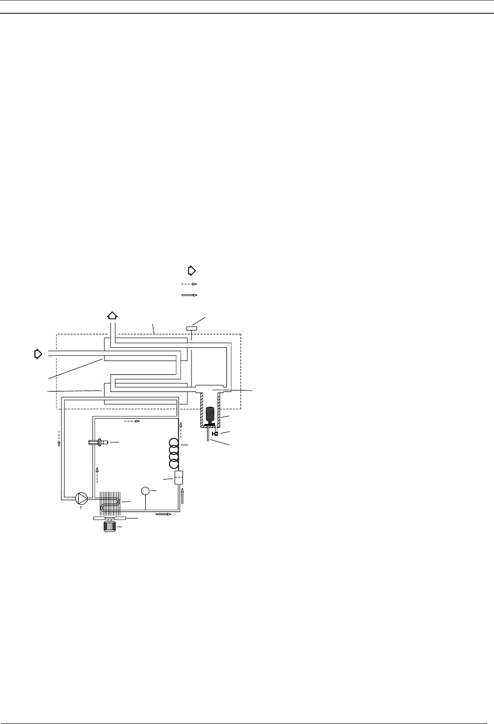
1.7 Air dryer on SF Full-Feature (Fig. 1.15)
Compressed air circuit
Wet compressed air enters heat exchanger (13) and is cooled by the outgoing, cold, dried air. Water in the
incoming air starts to condense. The air then flows through heat exchanger (11) where the refrigerant
evaporates and withdraws heat from the air. More water in the air condenses. The cold air then flows
through condensate separator (3) where the condensate is separated from the air. The condensate is
automatically drained through outlet (5). The cold, dried air then flows through heat exchanger (13), where it
is warmed up by the incoming air.
Refrigerant circuit
Compressor (M1) delivers hot, high-pressure refrigerant gas which flows through condenser (9) where most
of the refrigerant condenses.
The liquid flows through liquid refrigerant dryer/filter (12) to capillary tube (7). The refrigerant leaves the
capillary tube at evaporating pressure.
The refrigerant enters evaporator (11) where it withdraws heat from the compressed air by further evaporation
at constant pressure. The heated refrigerant leaves the evaporator and is sucked in by the compressor.
AO
AI
5
6
4
3
21
13
11
12
REFRIGERANT LIQUID (3)
REFRIGERANT GAS (2)
AIR (1)
50972D
7
10
S3
9
8
M2
M1
Text on Fig. 1.15
(1) Air
(2) Refrigerant gas
(3) Refrigerant liquid
AI Wet air inlet 5 Automatic condensate drain
AO Dry air outlet 6 Manual condensate drain valve
M1 Refrigerant compressor 7 Capillary tube
M2 Condenser fan motor 8 Condenser cooling fan
S3 Fan control switch 9 Refrigerant condenser
1 Pressure dewpoint sensor 10 Hot gas by-pass valve
2 Insulating block 11 Air/refrigerant heat exchanger/evaporator
3 Condensate separator 12 Liquid refrigerant dryer/filter
4 Condensate trap 13 Air/air heat exchanger
Fig. 1.15 Dryer on SF Full-Feature
Instruction book
2920 1521 00 17
2 INSTALLATION
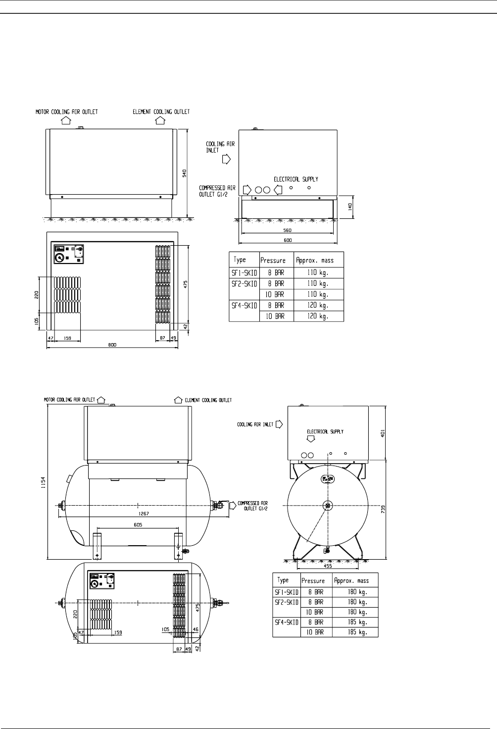
2.1 Dimension drawings (Figs. 2.1 up to 2.5)
9820 4052 00/1
55100D
(1) (2)
(3)
(4)
(5)
(6) (7) (8)
Fig. 2.1 Dimension drawing, SF 1-4 Skid
9820 4053 00/1
55101D
(1) (2)
(3)
(4)
(5)
(6) (7) (8)
Fig. 2.2 Dimension drawing, SF 1-4 Tank-mounted
Instruction book
2920 1521 00 18
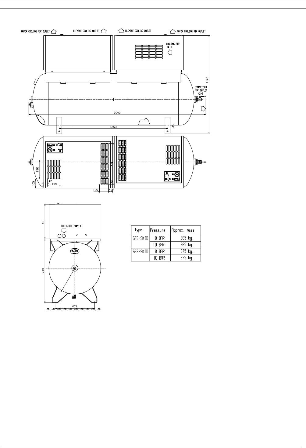
9820 4054 00/1
55102D
(1) (2) (2) (1)
(3)
(4)
(5)
(6) (7) (8)
Fig. 2.3 Dimension drawing, SF 6-8 Twin
Text on Figs.2.1/2.3
1 Motor cooling air outlet 5 Electrical supply
2 Element cooling outlet 6 Type
3 Cooling air inlet 7 Pressure
4 Compressed air outlet 8 Mass, approx.
Instruction book
2920 1521 00 19
(1)
(2)
(3)
(4)
(5)
(6)
(7)
(8) (9)
(10)
(11)
(8) (9)
(12)
(13)
(14)
(15)
9820 4027 00
55098D
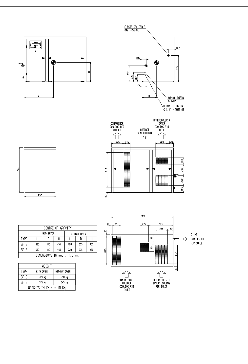
Fig. 2.4 Dimension drawing, SF 6-8 Multi
Instruction book
2920 1521 00 20
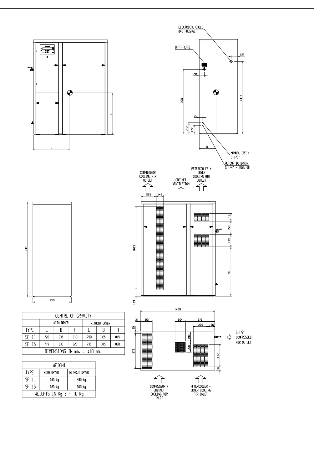
9820 4026 00
55099D
(1)
(16)
(2)
(3)
(4)
(5)
(6)
(7)
(8) (9)
(10)
(11)
(8) (9)
(12)
(13) (14)
(15)
Fig. 2.5 Dimension drawing, SF 11-15 Multi

Instruction book
2920 1521 00 21
Text on Figs. 2.4/2.5
(1) Electric cable
(2) Manual drain
(3) Automatic drain
(4) Compressor cooling air outlet
(5) Bodywork ventilation
(6) Aftercooler and dryer cooling air outlet
(7) Centre of gravity
(8) With dryer
(9) Without dryer
(10) Dimensions +/- 10 mm
(11) Weight
(12) Weight +/- 10 kg
(13) Compressor and bodywork cooling air inlet
(14) Aftercooler and dryer cooling air inlet
(15) Compressed air outlet
(16) Data plate
Instruction book
2920 1521 00 22
2.2 Installation proposal (Fig. 2.6)
9820 3960 00
55097D
(3)
(1)
(2)
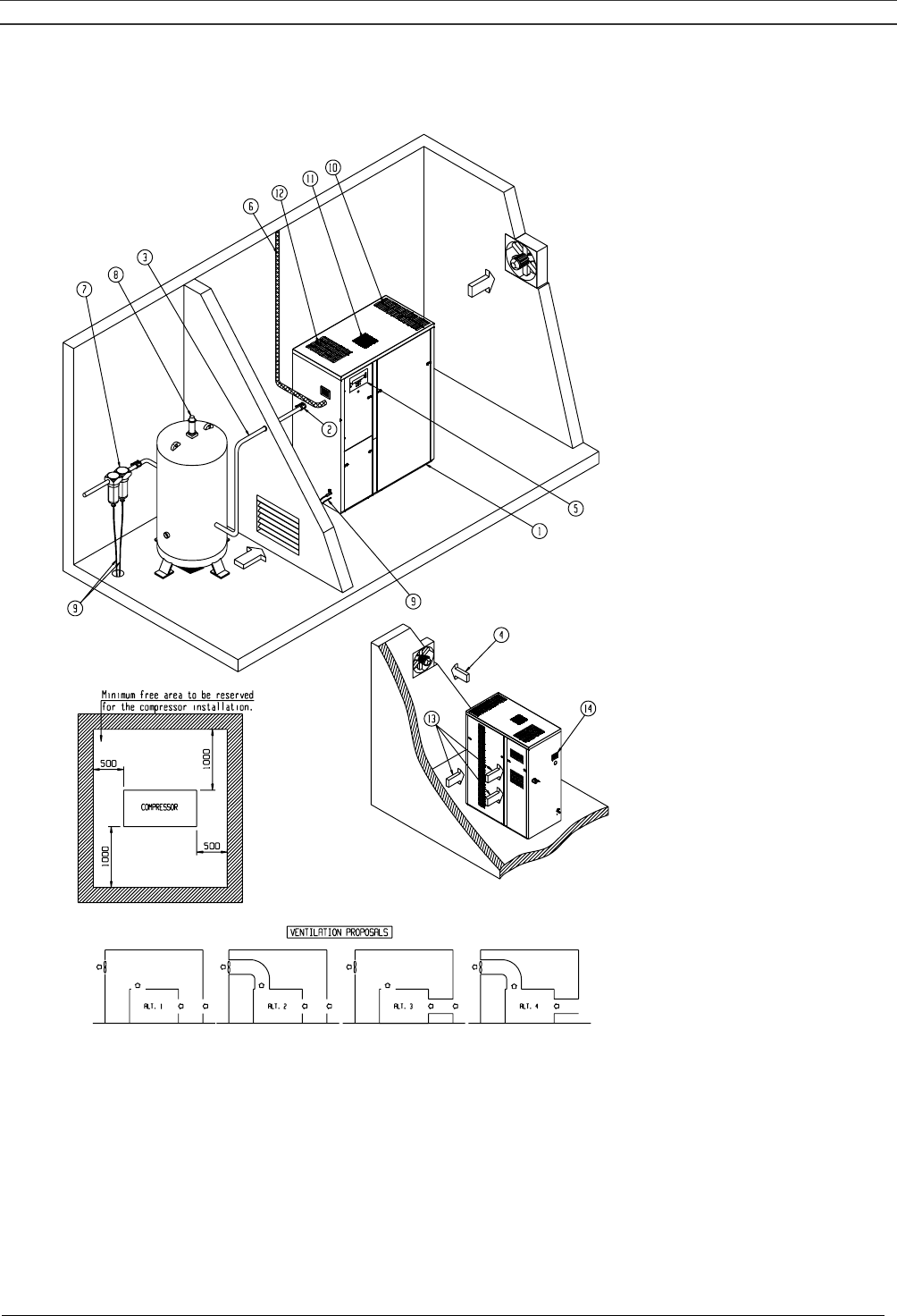
Fig. 2.6 Installation proposal, SF Multi
Text on Figs. 2.6
(1) Minimum free area
(2) Compressor
(3) Ventilation proposals

Instruction book
2920 1521 00 23
1 Install the compressor on a level floor, in a cool but frost-free room which is well-ventilated.
The air should be clean.
2 Position of compressed air outlet valve.
3 The maximum total pipe length can be calculated as follows:
L = (dP x d5 x P) / (450 x Qc1.85)
L = pipe length in m
dP = maximum allowable pressure drop (recommended 0.1 bar)
d = inner diameter of pipe in mm
P = compressor outlet pressure in bar absolute
Qc = free air delivery of compressor in l/s
4/13 Ventilation: the inlet grids and fan for compressor room ventilation should be installed in
such a way that any recirculation of cooling air to the compressor or dryer is avoided. The
air velocity to the grids must be limited to 5 m/s. The maximum allowable pressure drop
over the cooling air ducts is 50 Pa. If this pressure drop is exceeded, a fan is needed at the
outlet of the cooling air ducts. The maximum air temperature at the compressor intake
opening is 40 °C.
For alternatives 1 and 3, the required ventilation capacity to limit the compressor room
temperature can be calculated as follows:
Qv = 0.92 N/dT
Qv = required ventilation capacity in m³/s
N = shaft input of compressor in kW
dT= temperature increase in compressor room in °C
For alternatives 2 and 4, the fan capacity should match the compressor fan capacity at a
pressure head equal to the pressure drop caused by the outlet cooling air ducts.
5 Position of control cubicle with monitoring panel.
6 Position of main cable entry. See section 7.1 for the recommended electric cables. See
section 2.3 for connecting the power supply.
7 Optional filters can be installed in the pressure line downstream of the air outlet valve, e.g.:
A DD filter for general-purpose filtration. The filter traps solid particles down to 1 micron. A
PD filter for filtration down to 0.01 micron. A PD filter must be installed downstream of a DD
filter. If odours are undesirable, a filter of the QD type should be installed downstream of the
PD filter. It is recommended to install by-pass pipes to isolate the filters during servicing.
8 Safety valve.
9 Position of the drain flexibles. The flexibles towards the drain collector must not dip into the
water of the drain collector.
10 Cooling air outlet, compressor elements.
11 Bodywork ventilation outlet.
12 Cooling air outlet, air cooler and dryer.
14 Data plate
Instruction book
2920 1521 00 24
2.3 Electrical connections
General
The electrical installation must correspond to the local codes. The mains supply and earthing lines
must be of suitable size. See section 7.1.
The installation must be earthed and protected by fuses in each phase. An isolating switch must be
installed near the compressor. Make sure that this switch is open to isolate the compressor from
the mains before carrying out any connection.
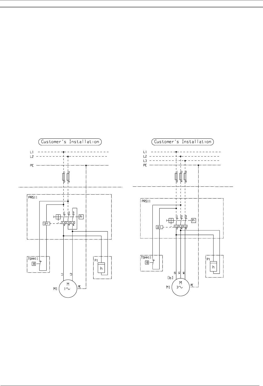
Connections
Skid - Tank-mounted - Twin
Connect the cable to terminals 1 and 3 (single-phase) or to terminals 1, 3 and 5 (3-phase) of pressure
switch (4-Fig. 1.10). Connect the earthing conductor to the earthing terminal. SF Twin have a
pressure switch for each compressor module; provide for each pressure switch separate supply
cables.
9820 3744 61
55103D
(1)
9820 3744 60
55104D
(1)
Single-phase 3-phase
Fig. 2.7 Service diagram, SF Skid - Tank-mounted – Twin
Text on Fig. 2.7
(1) Customer’s installation
Instruction book
2920 1521 00 25
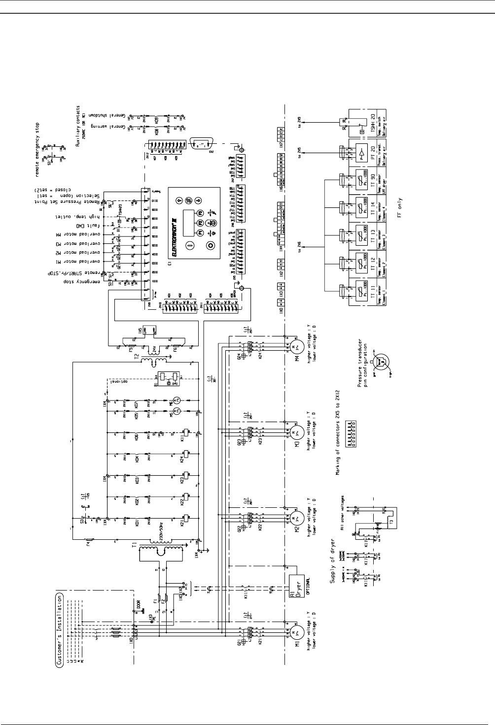
SF Multi
Connect the supply cable to terminals L1, L2 and L3 of terminal strip (1X0-Fig. 1.14), connect the
neutral conductor to terminal (N) and the earthing conductor to the earthing bolt (1X3).
O- O-O- O- O-
-
-
9820 3748 01/2
55105D
(1)
(2)
(3)
(4)
(5)
(6)
(7) (8)
(9)
(10) (11) (12) (13) (14) (15) (16)
(17)
(5)
(18)
(19)
(20)
(21)
(22)
(23)
(24)
(25)
(26)
(27)
(28)
(3) (3) (3)

Instruction book
2920 1521 00 26
A1 Dryer (optional)
F1/11 Fuses
K11 Auxiliary contactor, dryer
K21/24 Contactors
M1/4 Motors
M5 Fan motor, air cooler
M6 Fan motor, bodywork
PT20 Pressure sensor, air outlet
Q21/24 Circuit breakers
S3 Emergency stop button
TSHH20 Temperature switch, air outlet protection
TT11 Temperature sensor, compressor element 1 (lowest element)
TT12 Temperature sensor, compressor element 2
TT13 Temperature sensor, compressor element 3
TT14 Temperature sensor, compressor element 4 (highest element)
TT90 Temperature sensor, dewpoint temperature
T1/2 Transformers
1X0 Terminal strip, mains supply
1X2 Terminal strip, dryer
1X3/6 Terminal strips
Fig. 2.8 Service diagram for SF Multi
Text on Fig. 2.8
(1) Customer’s installation
(2) Door
(3) Higher voltage: Y
Lower voltage: D
(4) Dryer
(5) Optional
(6) Supply of dryer
(7) All other voltages
(8) Marking of connectors 2X5 to 2X12
(9) Pressure transducer: pin configuration
(10) Temperature sensor, element 1
(11) Temperature sensor, element 2
(12) Temperature sensor, element 3
(13) Temperature sensor, element 4
(14) Temperature sensor, LAT dryer
(15) Pressure transducer, delivery air
(16) Temperature switch, delivery air
(17) FF only
(18) Emergency stop
(19) Remote start/ pr. Stop
(20) Overload motor M1
(21) Overload motor M2
(22) Overload motor M3
(23) Overload motor M4
(24) Fault EWD
(25) High temperature outlet
(26) Remote pressure set point
Selection: Open = set 1 Closed = set 2
(27) Remote emergency stop
(28) Auxiliary contacts
Instruction book
2920 1521 00 27
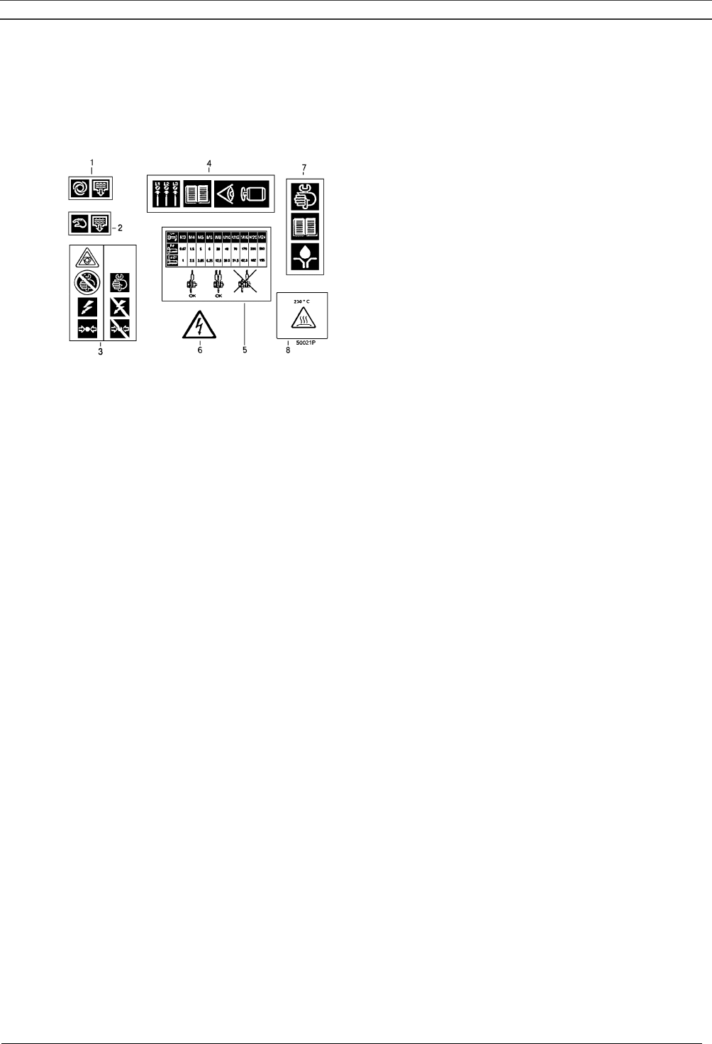
2.4 Pictographs
Fig. 2.9 shows examples of pictographs which may be used on the machine.
1 Automatic condensate drain
2 Manual condensate drain
3 Switch off voltage and depressurize compressor before
maintenance or repair
4 Before connecting compressor electrically, consult Instruction
book for motor rotation direction
5 Torques for steel (Fe) or brass (CuZn) bolts
6 Warning, voltage
7 Consult Instruction book before greasing
8 Warning, hot hose
Fig. 2.9 Pictographs

Instruction book
2920 1521 00 28
3 OPERATING INSTRUCTIONS
Safety precautions
The operator must apply all relevant safety precautions, including those mentioned in this book.
Outdoor/altitude operation
If the compressor is installed outdoors or if the air inlet temperature can be below 0 °C, precautions
must be taken. In this case, and also if operating at high altitude, consult Atlas Copco.
Before initial start-up
For SF Multi read section 8 to familiarize yourself with all regulator functions.
3.1 Initial start-up
1. Remove the red painted transport brackets:
- for SF Multi remove brackets (2-Fig. 5.1)
- for the other variants remove the brackets (one on each side of the frame)
2. For SF Multi check the settings of the overload relays (Q21, -22, -23, -24 - Fig. 1.14).
3. Connect the compressor electrically. See section 2.3.
4. Close the condensate drain valve: valve (1-Fig. 1.9 on SF Multi) or the valve underneath the air
receiver, if provided.
5. Switch on the voltage. Start and stop the compressor. On 3-phase compressors, check for
correct direction of rotation (arrows are provided on the motors). If the rotation direction is wrong,
switch off the voltage and reverse two incoming electric lines.
3.2 Starting
3.2.1 Multi
1. Open air outlet valve (3-Figs. 1.5/1.6).
2. Switch on the voltage.
3. Close condensate drain valve (1-Fig. 1.9).
4. Press start button (1-Fig. 1.11). The compressor starts running and automatic operation LED (8-
Fig. 1.11) lights up.
5. The regulator will automatically stop and start compressor modules, depending on the air
pressure.
6. On SF Full-Feature, the nominal pressure dewpoint will be reached after a few minutes.
3.2.2 Skid - Tank-mounted - Twin
1. Open air outlet valve (2-Figs. 1.2/1.4).
2. Switch on the voltage.
3. Check that the condensate drain valve underneath the air receiver (if installed) is closed.
4. Move switch (2-Fig. 1.10) to AUTO. The compressor starts running.
5. The drive motor(s) will automatically stop and start, depending on the air pressure.
Note: The maximum number of compressor starts is 30 per hour.

Instruction book
2920 1521 00 29
3.3 During operation
3.3.1 Multi
1. If the automatic operation LED (8-Fig. 1.11) is alight, the regulator is automatically controlling the
compressor modules (starting/stopping).
2. Check the readings on display (2-Fig. 1.11). In case of a warning or shut-down condition, see
section 8.3.
3. Check that condensate is discharged automatically from outlet (2-Figs. 1.9) during running.
Note: The dewpoint will deviate from nominal when the nominal conditions are exceeded. If the
dewpoint remains too high or unstable, consult section 6.
3.3.2 Skid - Tank-mounted - Twin
1. Check the starting and stopping pressures (1-Fig. 1.10).
2. Regularly open the drain valve underneath the air receiver for a few seconds, close the valve after
draining.
3.4 Stopping
3.4.1 Multi
1. Press stop button (9-Fig. 1.11).
2. Close air outlet valve (3-Figs. 1.5/1.6).
3. Switch off the voltage.
4. Open condensate drain valve (1-Fig. 1.9).
3.4.2 Skid - Tank-mounted - Twin
1. Move switch (2-Fig. 1.10) to OFF.
2. Close air outlet valve (2-Figs. 1.2/1.4).
3. Switch off the voltage.
4. Open the condensate drain valve underneath the air receiver (if provided) for a few seconds, close
the valve after draining.
3.5 Taking out of operation at end of compressor service life
1. Stop the compressor and close the air outlet valve.
2. Switch off the voltage and disconnect the compressor from the mains.
3. Open the condensate drain valve. Depressurize the compressor
4. Shut off and depressurize the part of the air net which is connected to the outlet valve. Disconnect
the compressor from the air net.
5. Disconnect the condensate piping from the local condensate drain system.

Instruction book
2920 1521 00 30
4 MAINTENANCE
Before carrying out any maintenance or repair:
1. Stop the compressor, switch off the voltage and open the isolating switch.
2. Close the air outlet valve (2-Figs. 1.2/1.4 or 3-Figs. 1.5/1.6) and open the manual drain valve: valve (1-
Fig. 1.9) on Multi or the valve underneath the air receiver, if provided.
4.1 Compressor drive motors
The motor bearings are greased for life.
4.2 Preventive maintenance schedule for the compressor
The schedule comprises a summary of the maintenance instructions. Read the respective section
before taking maintenance measures. The "longer interval" checks must also include the "shorter
interval" checks.
Carry out the service operations at the period or running hours mentioned below, whichever interval
comes first.
When servicing, replace all disengaged packings, e.g. gaskets, O-rings, washers.
Important
Use only authorized parts. Any damage or malfunction by the use of unauthorized parts is not
covered by Warranty or Product Liability.
Service plans on SF Multi
A number of service operations are grouped in plans, called Service plans I, A, B or D; see the
schedule below.
Each plan has a programmed time interval at which all service actions belonging to that plan are to be
carried out.
When reaching the interval, a message will appear on the screen indicating which Service plans are to
be carried out. After servicing, the intervals are to be reset. For detailed information, consult section
8.3.
Important
Always consult Atlas Copco in case any timer setting should be changed.
Instruction book
2920 1521 00 31
Period Running
hours
Service
Plan
See
section
See
notes
below
table
Operation
Daily -- -- 3.4 -- Drain condensate
" -- -- -- -- On SF Full-Feature, check dewpoint
Monthly 250 -- 5.1 1 Inspect air filter
3-monthly 500 -- -- -- Check pressure drop over Atlas Copco filters
(optional)
6-monthly -- -- 5.4 -- Operate safety valve
" -- -- -- -- Clean compressor
" -- -- -- -- On SF Full-Feature, brush or blow off the finned
surface of the condenser
" -- -- -- -- On SF Full-Feature, clean condensate trap
internally
Yearly -- -- 5.4 -- Test safety valve
" -- -- -- -- Have electrical components/shut-down switch
tested
" 2500 I 5.2 -- Check tension/condition of V-belt(s)
" 5000 A 5.1 -- Replace air filter
" 5000 A -- 2 Have ball valve mechanism of condensate trap
inspected
" 5000 A 5.2 -- Replace V-belt(s)
2-yearly 5000 B -- 2 Have orbiting scroll bearing greased
" 10000 B -- 2 Clean compressor element fan and duct. Clean
compressor element fins, have seals replaced
" 10000 B -- 2 Have pin crank bearings greased
Notes:
1. Check more frequently if operating in a dusty atmosphere. Check for cleanness and damage.
Replace a dirty or damaged filter by a new one.
2. Consult Atlas Copco.
Instruction book
2920 1521 00 32
5 ADJUSTMENTS AND SERVICING PROCEDURES
5.1 Air filter (1-Figs. 1.7/1.8)
1. Stop the compressor. Remove the filter cover and filter.
2. Clean the cover, if necessary. Discard damaged filters.
3. Fit a new filter and reinstall the cover.
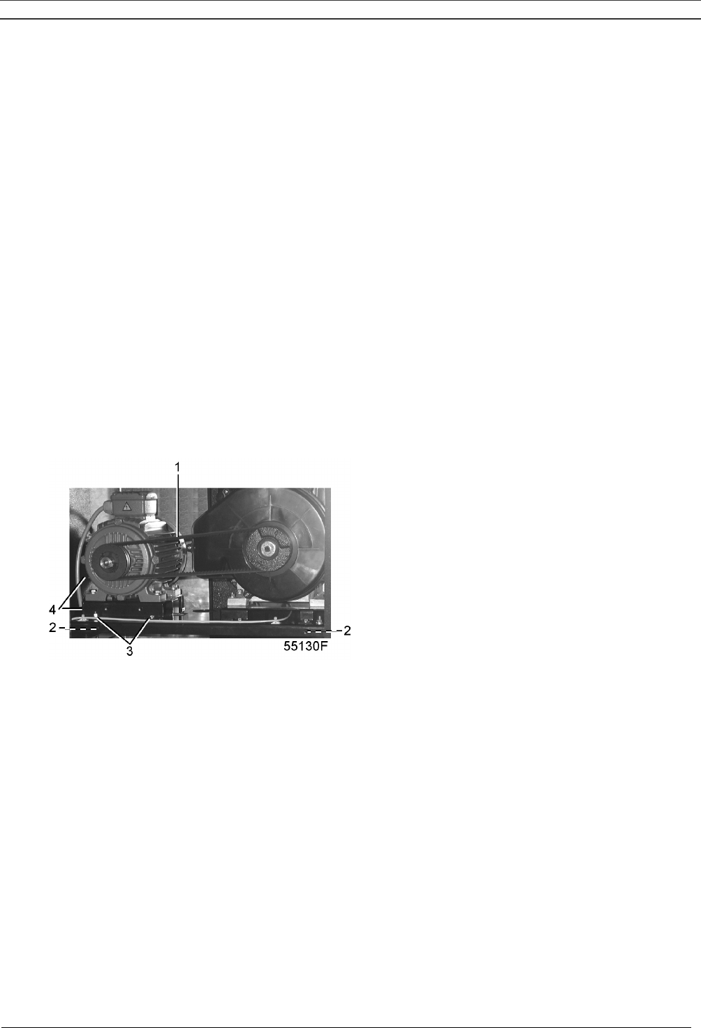
5.2 Belt exchange/tensioning (Fig. 5.1)
In case of two belts, the belts must be replaced as a set, even if only one of them seems worn.
Use Atlas Copco belts only. The part number of the belt set is mentioned in the Parts list.
1. Loosen motor hold-down bolts (3).
2. Loosen the belt tension by screwing bolts (4) equally and take out the belts.
3. Install new belts in the grooves of the pulleys.
4. Tension the belts by screwing bolts (4) equally. The tension is correct if the deflection is between
5 mm and 7 mm when exerting a force of 25 N on the belt midway between the pulleys. Make
sure that the pulleys remain aligned. The maximum out-of-line is:
- maximum parallel out-of-line: 0.5 mm
- maximum angular out-of-line: 0.5 degrees
5. Tighten bolts (3).
6. Check the belt tension after the first 500 running hours.
1 Belts
2 Transport brackets (2x - to be removed)
3 Motor hold-down bolts (4x)
4 Tensioning bolt
Fig. 5.1 Belt tensioning / transport fixation
5.3 Coolers
Keep the coolers clean to maintain cooling efficiency.
Remove any dirt from the coolers with a fibre brush. Never use a wire brush or metal objects. Then
clean by air jet in reverse direction of normal flow. If it should be necessary to wash the coolers with a
cleansing agent, consult Atlas Copco.

Instruction book
2920 1521 00 33
5.4 Safety valve
Operating
Operate the safety valve by unscrewing the knurled cap one or two turns. Retighten the cap.
Testing
The valve can be tested on a separate compressed air line. If the valve does not open at the pressure
marked on the valve, consult Atlas Copco.
Warning
No adjustments are allowed. Never run the compressor without safety valve.

Instruction book
2920 1521 00 34
6 PROBLEM SOLVING
Before carrying out any maintenance or repair:
1. Stop the compressor, switch off the voltage and open the isolating switch.
2. Close the air outlet valve (2-Figs. 1.2/1.4 or 3-Figs. 1.5/1.6) and open the manual drain valve: valve
(1-Fig. 1.9) on Multi or the valve underneath the air receiver, if provided.
1 Compressor does not start
a Loose connection
a Have electrical connections checked
b Receiver pressure too high
b Compressor will start when the net pressure drops to the minimum pressure
2 Safety valve blows
a Safety valve opens too soon
a Replace valve
3 Compressor capacity or pressure below normal
a Air consumption exceeds capacity of compressor
a Check equipment connected
b Choked air filter
b Remove and check filter. Replace if necessary
c Safety valve leaking
c Replace valve
d Drive belt(s) slipping
d Check condition of belt(s). Correct or replace as required
4 Compressor module overheating / compressor shut down by its air temperature switch
a Insufficient compressor cooling
a Improve ventilation of compressor room.
b Cooling fan out of order
b Check and correct
On SF Full-Feature also:
5 Pressure dewpoint too high
a Shortage of refrigerant
a Have circuit repaired or recharged
b Refrigerant compressor does not run
b See 7
c Condenser pressure is too high
c See 6
6 Condenser pressure too high or too low
a Fan control switch out of order
a Have switch replaced
b Condenser fan motor out of order
b Have fan motor inspected
c Ambient temperature too high
c Improve ventilation. If necessary, draw the cooling air from a cooler room
d Condenser externally clogged
d Clean condenser
7 Motor of refrigerant compressor stops or does not start
a Thermal protection of the motor has tripped
a Compressor will restart when the motor windings have cooled down
Instruction book
2920 1521 00 35
7 PRINCIPAL DATA
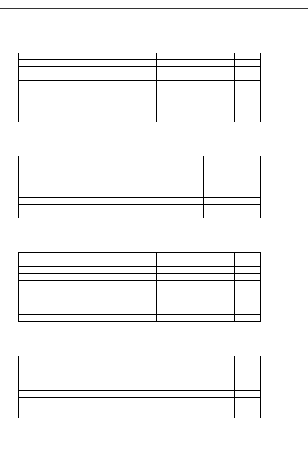
7.1 Electric cable size for SF1-8
Frequency Voltage SF1
single-
phase
SF2
single-
phase
SF2
3-phase
SF4
3-phase
SF6
3-phase
SF8
3-phase
IEC
50 Hz 230 V 2.5 mm² 2.5 mm² 2.5 mm² 2.5 mm² 2x 2.5
mm²
2x 2.5
mm²
50 Hz 400 V 2.5 mm² 2.5 mm² 2x 2.5
mm²
2x 2.5
mm²
60 Hz 380 V 2.5 mm² 2.5 mm² 2x 2.5
mm²
2x 2.5
mm²
50 Hz 500 V 2.5 mm² 2.5 mm² 2x 2.5
mm²
2x 2.5
mm²
CSA/UL
60 Hz 200/230 V AWG 12 AWG 12 AWG 12 AWG 10 2x AWG
12
2x AWG
10
60 Hz 440/460 V AWG 12 AWG 12 2x AWG
12
2x AWG
12
7.2 Electric cable size for SF 6-15 Multi
Frequency Voltage SF6
3-phase
SF8
3-phase
SF11
3-phase
SF15
3-phase
IEC
50 Hz 230 V 6 mm² 10 mm² 16 mm² 25 mm²
50 Hz 400 V 4 mm² 6 mm² 10 mm² 10 mm²
60 Hz 380 V 4 mm² 6 mm² 10 mm² 10 mm²
50 Hz 500 V 2.5 mm² 4 mm² 6 mm² 10 mm²
CSA/UL
60 Hz 200/230 V AWG 8 AWG 6 AWG 4 AWG 3
60 Hz 440/460 V AWG 10 AWG 10 AWG 8 AWG 6
60 Hz 575 V AWG 12 AWG 10 AWG 8 AWG 6
Instruction book
2920 1521 00 36
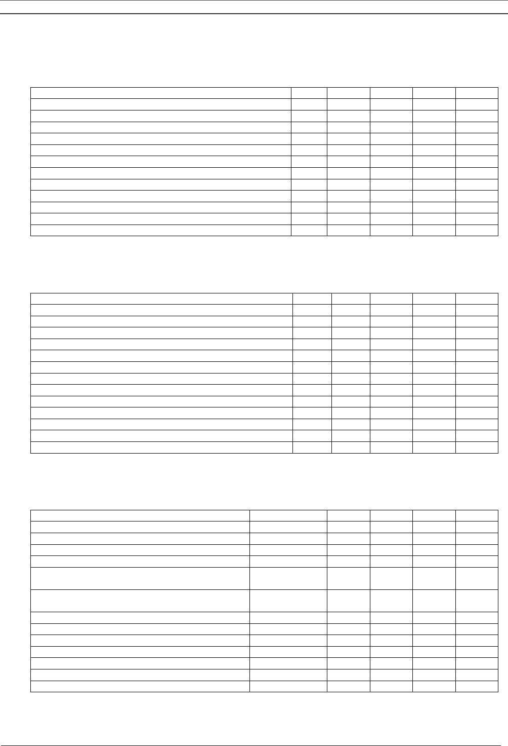
7.3 Overload relays for SF1-8
Frequency Voltage SF1
single-
phase
SF2
single-
phase
SF2
3-phase
SF4
3-phase
SF6
3-phase
SF8
3-phase
IEC
50 Hz 230 V 12 A 14.5 A 8.3 A 14 A 8.3 and 14 A 2x 14 A
50 Hz 400 V 4.8 A 8.2 A 4.8 and 8.2 A 2x 8.2 A
60 Hz 380 V 5.1 A 8.5 A 5.1 and 8.5 A 2x 8.5 A
50 Hz 500 V 3.8 A 6.5 A 3.8 and 6.5 A 2x 6.5 A
CSA/UL
60 Hz 230 V 10.2 A 14.7 A 9.2 A 15.3 A 9.2 and 15.3 A 2x 15.3 A
60 Hz 440/460 V 4.6 A 7.7 A 4.6 and 7.7 A 2x 7.7 A
Note: SF6 Twin have compressor modules of a different size, the first value is valid for the smaller
SF2 module and the second one is valid for the bigger SF4 module
7.4 Overload relays for SF6-15 Multi
Frequency Voltage SF6
3-phase
SF8
3-phase
SF11
3-phase
SF15
3-phase
IEC
50 Hz 230 V 8 and 14 A 2x 14 A 3x 14 A 4x 14 A
50 Hz 400 V 4.8 and 8 A 2x 8 A 3x 8 A 4x 8 A
60 Hz 380 V 5 and 8.5 A 2x 8.5 A 3x 8.5 A 4x 8.5 A
50 Hz 500 V 3.6 and 6.4 A 2x 6.4 A 3x 6.4 A 4x 6.4 A
CSA/UL
60 Hz 230 V 9 and 15 A 2x 15 A 3x 15 A 4x 15 A
60 Hz 440/460 V 4.5 and 7.5 A 2x 7.5 A 3x 7.5 A 4x 7.5 A
60 Hz 575 V 3.5 and 5.5 A 2x 5.5 A 3x 5.5 A 4x 5.5 A
Note: SF6 have compressor modules of a different size, the first value is valid for the smaller SF2
module (lower element) and the second one is valid for the bigger SF4 module (higher element)
Instruction book
2920 1521 00 37
7.5 Main fuses for SF1-8
Frequency Voltage SF1
single-
phase
SF2
single-
phase
SF2
3-phase
SF4
3-phase
SF6
3-phase
SF8
3-phase
IEC
50 Hz 230 V 20 A 20 A 20 A 20 A 2x 20 A 2x 20 A
50 Hz 400 V 20 A 20 A 2x 20 A 2x 20 A
60 Hz 380 V 20 A 20 A 2x 20 A 2x 20 A
50 Hz 500 V 20 A 20 A 2x 20 A 2x 20 A
CSA/UL
60 Hz 230 V 25 A 25 A 20 A 30 A 20 A 2x 30 A
60 Hz 440/460 V 15 A 15 A 15 A 2x 15 A
7.6 Main fuses for SF6-15 Multi
Frequency Voltage SF6
3-phase
SF8
3-phase
SF11
3-phase
SF15
3-phase
IEC
50 Hz 230 V 32 A 50 A 63 A 80 A
50 Hz 400 V 25 A 32 A 50 A 50 A
60 Hz 380 V 25 A 32 A 50 A 50 A
50 Hz 500 V 20 A 25 A 32 A 50 A
CSA/UL
60 Hz 230 V 45 A 60 A 80 A 110 A
60 Hz 440/460 V 25 A 30 A 45 A 60 A
60 Hz 575 V 20 A 25 A 35 A 45 A
7.7 Reference conditions/limitations
Reference conditions:
Air inlet pressure (absolute) 1 bar
Air inlet temperature 20 °C
Relative air humidity 0%
Nominal working pressure See values below
Limitations
Max. working pressure See values below
Max. ambient temperature 40 °C
Min. ambient temperature 0 °C
Instruction book
2920 1521 00 38
7.8 SF1-4 8bar 50 Hz 1)
Compressor type SF1 SF2 SF4
8 bar 8 bar 8 bar
Maximum working pressure bar(e) 8 8 8
Nominal working pressure bar(e) 7 7 7
Air temperature at outlet valve (Tank-
mounted/Twin), approx.
°C 30 32 40
Air temperature at outlet valve (Skid), approx. °C 38 45 65
Motor shaft speed r/min 2885 2885 2885
Shaft input kW 1.5 2.1 3.4
Sound pressure level dB(A) 65 67 68
7.9 SF2-4 10 bar 50 Hz 1)
Compressor type SF2 SF4
10 bar 10 bar
Maximum working pressure bar(e) 10 10
Nominal working pressure bar(e) 10 10
Air temperature at outlet valve (Tank-mounted/Twin), approx. °C 28 40
Air temperature at outlet valve (Skid), approx. °C 45 65
Motor shaft speed r/min 2885 2885
Shaft input kW 2.1 3.65
Sound pressure level dB(A) 67 68
7.10 SF1-4 100 psi 60 Hz 1)
Compressor type SF1 SF2 SF4
100 psi 100 psi 100 psi
Maximum working pressure bar(e) 8 8 8
Nominal working pressure bar(e) 7 7 7
Air temperature at outlet valve (Tank-
mounted/Twin), approx.
°C 30 32 40
Air temperature at outlet valve (Skid), approx. °C 38 45 65
Motor shaft speed r/min 1710 3485 3485
Shaft input kW 1.5 2.1 3.4
Sound pressure level dB(A) 65 67 68
7.11 SF2-4 145 psi 60 Hz 1)
Compressor type SF2 SF4
145 psi 145 psi
Maximum working pressure bar(e) 10 10
Nominal working pressure bar(e) 10 10
Air temperature at outlet valve (Tank-mounted/Twin), approx. °C 28 40
Air temperature at outlet valve (Skid), approx. °C 45 65
Motor shaft speed r/min 3485 3485
Shaft input kW 2.1 3.65
Sound pressure level dB(A) 67 68
Instruction book
2920 1521 00 39
7.12 SF6-15 Multi 8 bar 50 Hz 1)
Compressor type SF6 SF8 SF11 SF15
8 bar 8 bar 8 bar 8 bar
Maximum working pressure for SF Pack bar(e) 8 8 8 8
Maximum working pressure for SF Full-Feature bar(e) 7.75 7.75 7.75 7.75
Nominal working pressure bar(e) 7 7 7 7
Air temperature at outlet valve for SF Pack, approx. °C 26 28 30 32
Air temperature at outlet valve for SF Full-Feature, approx. °C 23 25 25 25
Motor shaft speed r/min 2885 2885 2885 2885
Shaft input kW 5.6 6.9 10.4 13.8
Sound pressure level dB(A) 61 62 60 63
For SF Full-Feature also:
Refrigerant type R134a R134a R134a R134a
Pressure dewpoint, approx 2) °C 3 3 3 3
7.13 SF6-15 Multi 10 bar 50 Hz 1)
Compressor type SF6 SF8 SF11 SF15
10 bar 10 bar 10 bar 10 bar
Maximum working pressure for SF Pack bar(e) 10 10 10 10
Maximum working pressure for SF Full-Feature bar(e) 9.75 9.75 9.75 9.75
Nominal working pressure for SF Pack bar(e) 10 10 10 10
Nominal working pressure for SF Full-Feature bar(e) 9.75 9.75 9.75 9.75
Air temperature at outlet valve for SF Pack, approx. °C 26 28 30 32
Air temperature at outlet valve for SF Full-Feature, approx. °C 25 25 25 25
Motor shaft speed r/min 2885 2885 2885 2885
Shaft input kW 5.9 7.5 11.3 15.0
Sound pressure level dB(A) 61 62 60 63
For SF Full-Feature also:
Refrigerant type R134a R134a R134a R134a
Pressure dewpoint, approx. 2) °C 3 3 3 3
7.14 SF6-15 Multi 100 psi 60 Hz 1)
Compressor type SF6 SF8 SF11 SF15
100 psi 100 psi 100 psi 100 psi
Maximum working pressure for SF Pack bar(e) 8 8 8 8
Maximum working pressure for SF Full-Feature bar(e) 7.75 7.75 7.75 7.75
Nominal working pressure bar(e) 7 7 7 7
Air temperature at outlet valve for SF Pack,
approx.
°C 26 28 29 30
Air temperature at outlet valve for SF Full-
Feature, approx.
°C 23 25 25 25
Motor shaft speed r/min 3495 3495 3495 3495
Shaft input SF Pack kW 5.7 7.1 10.7 14.2
Shaft input SF Full-Feature kW 5.8 7.2 10.8 14.4
Sound pressure level dB(A) 61 62 60 63
For SF Full-Feature also:
Refrigerant type R134a R134a R134a R134a
Pressure dewpoint, approx 2) °C 3 3 3 3

Instruction book
2920 1521 00 40
7.15 SF6-15 Multi 125 psi 60 Hz 1)
Compressor type SF6 SF8 SF11 SF15
125 psi 125 psi 125 psi 125 psi
Maximum working pressure for SF Pack bar(e) 9.1 9.1 9.1 9.1
Maximum working pressure for SF Full-Feature bar(e) 8.85 8.85 8.85 8.85
Nominal working pressure bar(e) 8.6 8.6 8.6 8.6
Air temperature at outlet valve for SF Pack, approx. °C 26 28 30 30
Air temperature at outlet valve for SF Full-Feature,
approx.
23 25 25 25
Motor shaft speed 3505 3505 3505 3505
Shaft input for SF Pack kW 5.8 7.4 11.0 14.7
Shaft input for SF Full-Feature kW 5.9 7.4 11.1 14.8
Sound pressure level dB(A) 61 62 60 63
For SF Full-Feature also:
Refrigerant type R134a R134a R134a R134a
Pressure dewpoint, approx. 2) °C 3 3 3 3
7.16 SF6-15 Multi 145 psi 60 Hz 1)
Compressor type SF6 SF8 SF11 SF15
145 psi 145 psi 145 psi 145 psi
Maximum working pressure for SF Pack bar(e) 10 10 10 10
Maximum working pressure for SF Full-Feature bar(e) 9.75 9.75 9.75 9.75
Nominal working pressure for SF Pack bar(e) 10 10 10 10
Nominal working pressure for SF Full-Feature bar(e) 9.75 9.75 9.75 9.75
Air temperature at outlet valve for SF Pack, approx. °C 26 28 30 32
Air temperature at outlet valve for SF Full-Feature,
approx.
23 25 25 25
Motor shaft speed 3505 3505 3505 3505
Shaft input kW 5.9 7.5 11.3 15.0
Sound pressure level dB(A) 61 62 60 63
For SF Full-Feature also:
Refrigerant type R134a R134a R134a R134a
Pressure dewpoint, approx. 2) °C 3 3 3 3
Footnotes chapter 7
1) At reference conditions
2) At 20 °C / 100% relative humidity
Instruction book
2920 1521 00 41
8 REGULATOR FUNCTIONS FOR SF MULTI
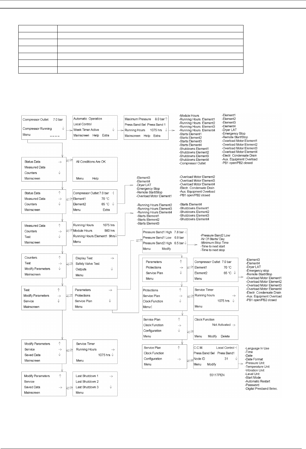
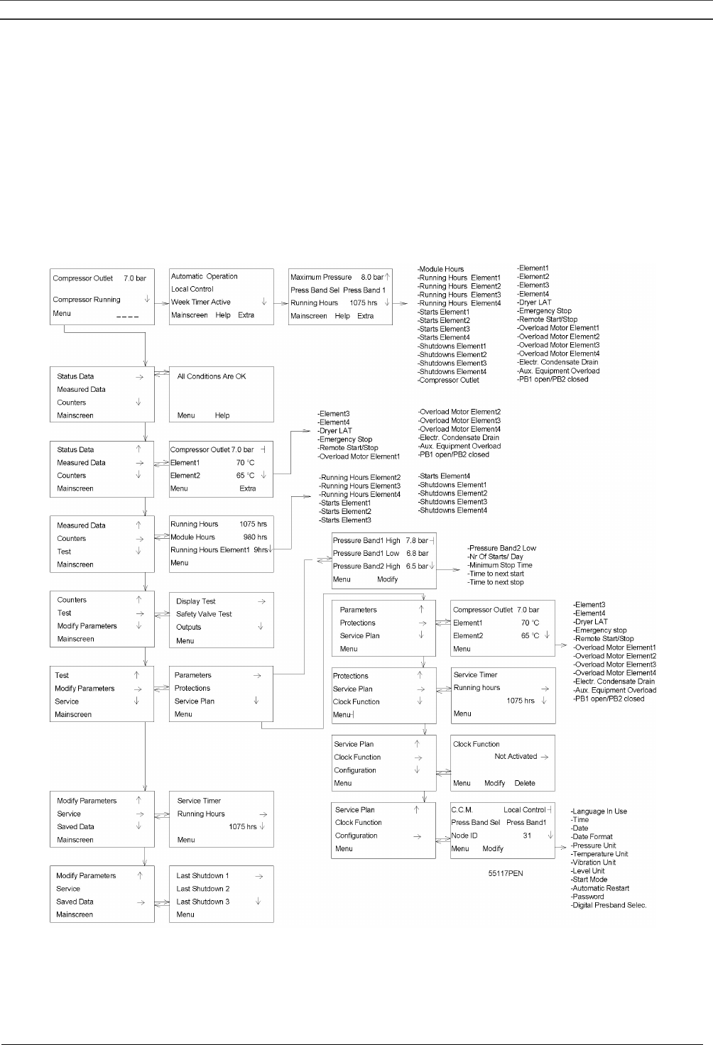
8.1 Menu-driven control programs
To facilitate programming and controlling the compressor, menu-driven programs are implemented in
the electronic module.
A simplified menu flow is shown in Fig. 8.1.
Fig. 8.1 Menu flow SF15 Workplace Full-Feature
Instruction book
2920 1521 00 42
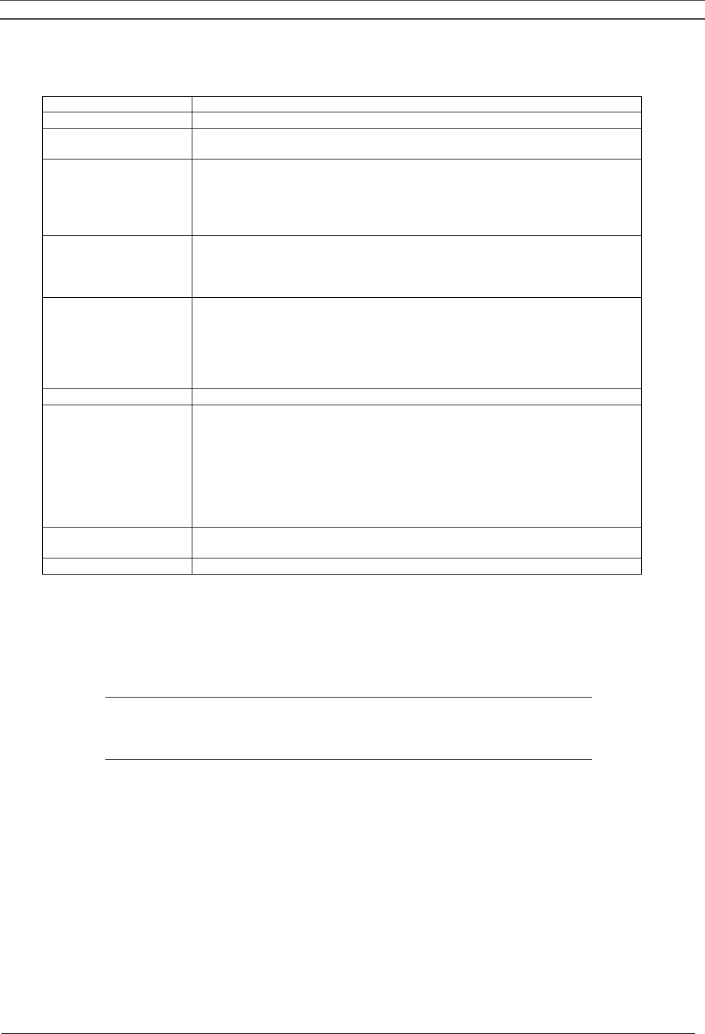
8.1.1 Function of control programs
Program/Function Description
Main screen Shows in short the operation status of the compressor. It is the gateway
to all functions. See Fig. 8.2.
Status data Calling up the status of the compressor protection functions:
- shut-down
- service warning
- warning
Resetting of a shut-down and service condition.
Measured data Calling up:
- actually measured data
- status of some inputs such as the motor overload protection per
compressor module
Counters Calling up the:
- running hours
- regulator (module) hours
- running hours per compressor module
- number of starts per compressor module
- number of shut-downs per compressor module
Test Allows a display test.
Modify parameters Modifying the settings for:
- parameters (e.g. number of starts per day)
- protections (e.g. dewpoint temperature of dryer for Full-Feature
machines)
- service plans (see section 8.10)
- clock functions (automatic compressor start/stop/pressure band
commands)
- configuration (time, date, display language, …)
Service Calling up service plans and resetting the timers after carrying out the
service actions belonging to a plan. See section 8.13.
Saved data Calling up the saved data: last shut-down data
8.1.2 Main screen
When the voltage is switched on, the Main screen is shown automatically, showing in short the
operation status of the compressor.
Compressor Outlet 7.0 bar
Compressor Running ↓
Menu - - - -
F1 F2 F3
Fig. 8.2 Main screen, typical example
If the function keys or arrow keys are not used for some minutes, the display will automatically return
to the Main screen.
Whenever displayed on a submenu screen, press the key "Mainscreen" to return to the Main screen.

Instruction book
2920 1521 00 43
Line Indicates Remarks
1 Sensor which is active
and the actual reading
The unit for pressure can be bar, psi or kg/cm2 depending on the
programmed selection. The unit for temperature can be °C or °F.
See section 8.12.
2 - -
3 Compressor status
Examples:
- Compressor Off
- Compressor Running
3 Shut-down
If the unit is shut down, the regulator will automatically show a shut-
down message on the display (see section 8.3). It remains possible
to have a closer look at other parameters related to the shut-down
by means of the menus.
3 Service required Indicates that the unit needs servicing. Consult section 8.13 to find
out the exact cause for this message.
3 Sensor error
Indicates that a sensor is out of order:
- Outlet pressure transducer
- On Full-Feature compressors, the dewpoint sensor
Stop the compressor. Switch off the voltage and depressurize the
compressor. Check the sensor wiring. Replace the sensor or
transducer, if necessary.
3 Remote control Indicates that the compressor is set in remote control. Consult Atlas
Copco.
4 Functions of keys
below display
See section 1.5.7.
Symbols: Indicating the status of each compressor module
- indicating that the compressor module is available (ready to run)
▄ indicating that the compressor module is running
- (blinking) indicating that the compressor module is not available (due to
minimum stop time or too many starts)
4
* (blinking) indicating that the compressor module is shut down
Note
When more than one message needs to be displayed (e.g. both warning and service), the
messages will be displayed one after the other for 3 seconds.
Press key (F3) on the main screen to check which compressor module is running or stopped.
Element 1 Stopped
Element 2 Running
Element 3 Stopped ↓
Menu
F1 F2 F3
Fig. 8.3 Element status screen, typical example

Instruction book
2920 1521 00 44
8.1.3 Calling up other menus
Starting from the Main screen:
- Use the ↓ key for a quick look at the actual compressor status (see section 8.2)
- Press the key "Menu" (F1), the option "Status data" will be followed by a horizontal arrow:
- either press the tabulator key (5) to select this menu
- or use the ↓ key to scroll until the desired submenu is followed by a horizontal arrow and then
press the tabulator key (5) to select this menu
8.2 Quick look at actual compressor status
Procedure
1. Starting from the Main screen (see section 8.1.2), press the ↓ key: A screen similar to the one
below appears:
Automatic Operation
Local Control
Week Timer Active ↓
Mainscreen Help Extra
F1 F2 F3
Fig. 8.4 Example of an actual compressor status display
Line 1 indicates the automatic or manual operation status of the regulator:
"Automatic operation" means that the regulator automatically adapts the operation of the
compressor, i.e. starting and stopping the compressor modules according to the programmed
parameters.
Line 2 indicates whether the regulator operates in local control, remote control or LAN control mode:
"Local control" means that the start/stop buttons on the keyboard are activated.
"Remote control" means that these functions are controlled remotely. Consult Atlas Copco.
“LAN control” means that the compressor can be controlled by an ES controller.
Line 3 indicates whether the timer, which generates time-based start and stop commands is activated
or not. See section 8.11.
See section 1.5.7 for the functions of the keys "Mainscreen", "Help" and "Extra".
2. Press the ↓ key to get other data (actual compressor conditions of the compressor) as shown in
Fig. 8.1.
Instruction book
2920 1521 00 45
8.3 Status data menu
The status data submenu gives information regarding the status of the compressor protection
functions (shut-down, service warning and warning) and allows resetting of a shut-down and service
condition.
Procedure
Starting from the Main screen (see section 8.1.2):
- Press the key "Menu" (F1), the option "Status data" will be followed by a horizontal arrow
- Press the tabulator key (5)
8.3.1 No message exists
In this case, LED (7) is out and the message on the display indicates that all conditions are normal
(Fig. 8.5):
All Conditions are OK
Menu Help
F1 F2 F3
Fig. 8.5 Example of a status data screen
8.3.2 A shut-down message exists
In case the compressor is shut down, LED (7) will blink. A shut-down message exists after an
emergency stop or after the temperature switch (TSHH20-Fig.2.8) has tripped (indicated on the
display as Aux. Equipment Overload).
In case of a shut-down due to an emergency stop, a screen similar to the one below will appear:
Emergency Stop Open
Shutdown Open
Menu *** *** Reset
F1 F2 F3
Fig. 8.6 Example of a status data screen
1. The indicators (***) are blinking. The screen shows that the compressor is shut down due to an
emergency stop. The contacts of the emergency switch are open. The setting of the shut-down is
open.

Instruction book
2920 1521 00 46
2. It remains possible to scroll through other menus, e.g. to check the values of other parameters.
When returning to the Status data menu, the option "Shutdowns" will blink. This option can be
selected by pressing the tabulator key (5) to return to the shut-down screen (Fig. 8.6).
Shut-down reset
1. Switch off the voltage, depressurize the compressor and remedy the trouble. After remedying,
switch on the voltage and press the key "Reset" (F3).
2. Press the keys "Menu" and "Mainscreen" to return to the Main screen and restart the compressor
by means of button I.
8.3.3 A warning message exists
1. If a shut-down warning exists, LED (7) is alight. The Main screen will change into a screen similar
to the one below:
Compressor Outlet 7.0 bar
** Warning
**↓
Menu *** *** * - - -
F1 F2 F3
Fig. 8.7 Example of a warning screen
2. The indicators (***) are blinking and the message **Warning** appears alternately with the
messages indicating whether the compressor is in operation or not (Compressor Running or
Compressor Off).
3. Press the key "Menu" (F1) and the tabulator key (5) to select the Status Data menu, the option
"Protection" is blinking.
4. Scroll to this option and select it by pressing the tabulator key (5): option "Warnings" blinks. Scroll
to this option and select it by pressing the tabulator key (5). A screen similar to the one in Fig. 8.8
appears:
Element 1 80 °C
Warning Maximum 75 °C
Menu *** ***
F1 F2 F3
Fig. 8.8 Example of a warning screen
The screen shows that the temperature at the outlet of element 1 (80 °C) is too high.
5. Stop the compressor by means of button O and wait until the compressor has stopped.
6. Switch off the voltage, inspect the compressor and remedy.
7. The warning message will disappear automatically as soon as the warning condition disappears.

Instruction book
2920 1521 00 47
8.3.4 A service warning message exists
1. LED (7) is alight and the main screen will change into a screen similar to that shown in Fig. 8.9.
Compressor Outlet 7.0 bar
** Service Required
**↓
Menu *** *** - - - -
F1 F2 F3
Fig. 8.9 Example of a service warning screen
2. The indicators (***) are blinking and the service warning message appears alternately with the
messages indicating whether the compressor is in operation or not (Compressor Running or
Compressor Off).
3. Press the key "Menu" (F1) and the tabulator key (5) to select the Status data menu: the option
"Service" is blinking.
4. Scroll to this option and select it by pressing the tabulator key (5), two options may blink:
"Inputs": option is not applicable.
"Plan": if a service plan interval is exceeded. See section 8.15.2.
5. Stop the compressor and switch off the voltage.
6. The service message was referring to "Plan": carry out the service actions related to the indicated
plans. Reset the timers of the related plans as described in section 8.13.
8.4 Measured data menu
Function
To call up information regarding the actually measured data and the status of some inputs such as the
motor overload protection per compressor module.
Procedure
1. Starting from the Main screen (see section 8.1.2):
- press the key "Menu" (F1)
- press the ↓ key until the option "Measured data" is followed by a horizontal arrow
- press the tabulator key (5) to activate the menu
Compressor Outlet 7.0 bar ┤
Element 1 75 °C
Element 2 70 °C ↓
Menu Extra
F1 F2 F3
Fig. 8.10 Example of a measured data screen
Instruction book
2920 1521 00 48
2. By pressing the ↓ key, a number of actually measured data can be found (see Fig. 8.1).
3. If one of the sensors is linked to a shut-down, service or warning function, both the actually
measured value as well as the corresponding shut-down, warning or service level can be called up
by pressing the tabulator key (5).
8.5 Counters menu
Function
To allow the operator to call up the:
- running hours
- regulator (module) hours (the hours the module has been under tension)
- running hours per compressor module
- starts per compressor module
- shutdowns per compressor module
Procedure
1. Starting from the Main screen (see section 8.1.2):
- press the key "Menu" (F1)
- press the ↓ key until the option "Counters" is followed by a horizontal arrow
- press the tabulator key (5) to activate the menu
2. By pressing the ↓ key, the above-mentioned data can be found (see also Fig. 8.1).
8.6 Test menu
Function
To carry out a display test, i.e. to check whether the display and LEDs are still intact.
Procedure
1. Starting from the Main screen (see section 8.1.2):
- press the key "Menu" (F1)
- press the ↓ key until the option "Test" is followed by a horizontal arrow
- press the tabulator key (5) to activate the menu
2. The option "Display test" will be followed by a horizontal arrow.
3. After pressing the tabulator key (5), the regulator will generate a series of patterns on the display
which enable the operator to check that each pixel still functions normally; at the same time the
LEDs are lit.

Instruction book
2920 1521 00 49
8.7 Modify parameters menu
Function
The menu allows the operator to program:
- Parameters, see section 8.8.
- Protections settings, see section 8.9.
- Service plan settings, see section 8.10.
- Clock function settings, see section 8.11.
- Configuration settings, see section 8.12.
8.8 Modifying parameters
Function
To modify a number of parameters as mentioned below and in Fig. 8.1.
- Pressure Band 1 High
- Pressure Band 1 Low
- Pressure Band 2 High
- Pressure Band 2 Low
- Number Of Starts/Day (per compressor module)
- Minimum Stop Time (i.e. the time period during which the compressor, if stopped automatically,
remains stopped whatever happens with the air net pressure)
- Power recovery time (if automatic restart after voltage failure is activated) 3)
- Restart delay (can be programmed, allowing e.g. compressors to be restarted one after the other)
- Time to next start (time between the starting of two compressor modules)
- Time to next stop (time between the stopping of two compressor modules during regulation)
Procedure
1. Starting from the Main screen (see section 8.1.2):
- press the key "Menu" (F1)
- press the ↓ key until the option "Modify Parameters" is followed by a horizontal arrow
- press the tabulator key (5) to activate the menu
2. The first option ("Parameters") will be followed by a horizontal arrow.
3. Press the tabulator key (5): the first item ("Pressure Band 1 High") and its setting will appear.
4. Use the ↓ key to scroll until the parameter to be modified is followed by a horizontal arrow.
Instruction book
2920 1521 00 50
8.8.1 Modifying the pressure bands
If desired, the operator can program two pressure bands (band 1 and band 2) with different pressure
settings. The settings for band 1 are indicated as "Pressure Band 1 High" and "Pressure Band 1
Low", the settings for band 2 are indicated as " Pressure Band 2 High " and " Pressure Band 2 Low ".
Example:
For pressure band 1:
- Pressure Band 1 Low: 6.8 bar
- Pressure Band 1 High: 7.8 bar
For pressure band 2:
- Pressure Band 2 Low: 5.5 bar
- Pressure Band 2 High: 6.5 bar
Procedure
1. Consult the section above to select the parameter Pressure Band 1 High:
Pressure Band 1 High 7.8 bar ┤
Pressure Band 1 Low 6.8 bar
Pressure Band 2 High 6.5 bar ↓
Menu Modify
F1 F2 F3
Fig. 8.11 Modify parameters menu
2. The screen shows that the current setting of Pressure Band 1 High is 7.8 bar(e). To modify this
setting, press the key "Modify" (F2):
Pressure Band 1 High 7.8 bar
Program Limits Cancel
F1 F2 F3
Fig. 8.12 Modify parameters menu
3. The key "Limits" (F2) can be used to find the limitations for the parameter. Use the ↓ or ↑ arrow
key to change the value.
4. Press the key "Program" (F1) to program the new setting or the key "Cancel" (F3) to cancel the
modification operation.
5. The procedure to modify the Pressure Band 1 Low is similar to the description above.
6. If required, repeat the procedure for the Pressure Band 2 High and Pressure Band 2 Low
(pressure band 2).
Instruction book
2920 1521 00 51
8.9 Modifying protection settings
Function
1. To modify protection settings: warning ("Warning"), e.g. Dryer LAT (Low Ambient Temperature) on
Full-Feature machines
2. To check some compressor conditions, e.g. the status of the motor overload contacts per
compressor module. The list of parameters is shown in Fig. 8.1.
Note
Some parameters cannot be modified.
Procedure
1. Starting from the Main screen (see section 8.1.2):
- press the key "Menu" (F1)
- press the ↓ key until the option "Modify parameters" is followed by a horizontal arrow
- press the tabulator key (5) to activate the menu
2. Use the ↓ key to scroll until the option "Protections" is followed by a horizontal arrow.
3. Press the tabulator key (5): the first item ("Compressor outlet") and its value will appear.
4. Use the ↓ key to scroll until the parameter to be modified or checked is followed by a horizontal
arrow.
5. press the tabulator key (5) to select the parameter
8.9.1 Checking protections for compressor modules
1. Consult the section above to select the parameter Element 1:
Element 1 70 °C
Warning Maximum 75 °C
Back
F1 F2 F3
Fig. 8.13 Modify parameters menu
2. The screen shows that the current temperature is 70 °C and that the shut-down setting is 75 °C.

Instruction book
2920 1521 00 52
8.9.2 Modifying protections for Dryer LAT on Full-Feature machines
1. Consult the section above to select the parameter Dryer LAT (Low Ambient Temperature):
Dryer LAT 10 °C
→
Warning Maximum 25 °C
↓
Back Modify
F1 F2 F3
Fig. 8.14 Modify parameters menu
2. The screen shows that the Dryer LAT is 10 °C and that the shut-down setting is 25 °C. To modify
this setting, press the key "Modify" (F2):
Dryer LAT 10 °C
Warning Maximum 25 °C
Program Limits Cancel
F1 F2 F3
Fig. 8.15 Modify parameters menu
3. The key "Limits" (F2) can be used to find the limitations for the parameter. Use the ↓ or ↑ arrow
key to change the value.
4. Press the key "Program" (F1) to program the new setting or the key "Cancel" (F3) to cancel the
modification operation.
Note:
The modifying procedure for other settings is similar. For some settings, a delay can be
programmed. See section 8.15.
8.10 Modifying service plans
Function
To modify the hour intervals for the Service plans.
Service plans
The service operations to be carried out are grouped in plans, called Service plan A, B, D or I. When
reaching an interval, a message will appear on the screen indicating which Service plans are to be
carried out.

Instruction book
2920 1521 00 53
Important
Always consult Atlas Copco in case any timer setting should be changed. The intervals must not
exceed the periods below and must coincide logically.
Programmed service plan intervals
Service plans Intervals
Service plan I Each 2500 running hours
Service plan A Each 5000 running hours
Service plan B Each 10000 running hours
Service plan D Each 20000 running hours
Resulting service actions to be carried out
Service actions according to At
Service plan I 2500 running hours
Service plan I and A 5000 running hours
Service plan I, A and B 10000 running hours
Service plan I, A, B and D 20000 running hours
… …
Procedure
1. Starting from the Main screen (see section 8.1.2):
- press the key "Menu" (F1)
- press the ↓ key until the option "Modify parameters" is followed by a horizontal arrow
- press the tabulator key (5) to activate the menu
2. Use the ↓ key to scroll until the option "Service plan" is followed by a horizontal arrow.
3. Press the tabulator key (5): a screen similar to the one below will appear:
Service Timer
Running Hours →
1075 hrs
↓
Menu
F1 F2 F3
Fig. 8.16 Service menu
The screen shows the actual running hours (1075).

Instruction book
2920 1521 00 54
4. Press the tabulator key (5): a screen similar to the one below will appear:
Service Timer
Level A
5000 hrs
↓
Menu Modify
F1 F2 F3
Fig. 8.17 Service plan menu
5. The screen indicates that the level for Service plan A is set at 5000 running hours.
6. Press the "Modify" key. The key "Limits" (F2) can be used to find the limitations for the parameter.
Use the ↓ or ↑ arrow key to modify the interval.
7. Press the key "Program" (F1) to program the new setting or the key "Cancel" (F3) to cancel the
modification operation.
8. The procedure to modify the Service plans B, D and I are carried out in a similar way. Press the ↓
key in Fig. 8.17 to find the other Service plans.
8.11 Programming Clock function
To program:
- time-based start/stop commands for the compressor
- time-based change-over commands for the net pressure band (see also section 8.8.1)
8.11.1 Programming start/stop/pressure band commands
In this example, the compressor will be programmed as follows:
- On Monday at 06:15 starting in pressure band 1
- On Friday at 18:00 changing over to pressure band 2
- On Saturday at 18:00 stopping
1. Starting from the Main screen (see section 8.1.2):
- press the key "Menu" (F1)
- press the ↓ key until the option "Modify parameters" is followed by a horizontal arrow
- press the tabulator key (5) to activate the menu
2. Use the ↓ key to scroll until the option "Clock function" is followed by a horizontal arrow. Press the
tabulator key (5), following screen appears:
Clock Function
Not activated
→
Menu Modify Delete
F1 F2 F3
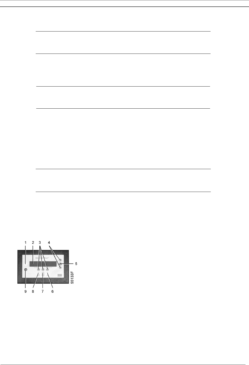
Instruction book
2920 1521 00 55
3. Press the tabulator key (5), following screen appears:
Monday →
Tuesday
Wednesday
↓
Back Delete
F1 F2 F3
4. Use the ↓ or ↑ key until the day on which a command must be programmed is followed by a right
pointing arrow. Press the tabulator key (5), following screen appears:
--:-- -------------------------------------- ┤
--:-- --------------------------------------
--:-- --------------------------------------
↓
Back Modify Delete
F1 F2 F3
5. Press the key "Modify" (F2). The first two digits will flash. Use the ↓ or ↑ key to enter "06". Press
the tabulator key to jump to the following two dashes. Use the ↓ or ↑ key to enter "15". Press the
tabulator key to jump to the row of dashes. Use the ↓ or ↑ key to enter the command Start. Press
the key "Program" to program the command: 06:15 Start
6. Press the ↓ key: the symbol ┤ indicates that the second line is accessible. Press the key "Modify"
and modify this line to the following command line: 06:15 Pressure Band 1 in a similar way.
7. Press the key "Back" (F1) and scroll to "Friday":
Thursday
↑
Friday
→
Saturday
↓
Back Delete
F1 F2 F3
8. Programming the command to change over at 18 o’clock to Pressure Band 2 is carried out in a
similar way as described above.
9. Press the key "Back" (F1) and scroll to "Saturday". Programming the command to stop at 18
o’clock is carried out in a similar way as described above.
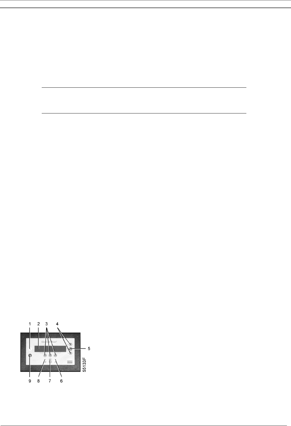
Instruction book
2920 1521 00 56
8.11.2 To activate/deactivate the timer
1. Starting from the Main screen (see section 8.1.2):
- press the key "Menu" (F1)
- press the ↓ key until the option "Modify parameters" is followed by a horizontal arrow
- press the tabulator key (5) to activate the menu
2. Use the ↓ key to scroll until the option "Clock function" is followed by a horizontal arrow. Press the
tabulator key (5), following screen appears:
Clock Function
Not activated
→
Menu Modify Delete
F1 F2 F3
3. Press the key "Modify", "Not activated" starts blinking.
4. Press the ↓ key, "Not activated" changes into "Activated".
5. Press the key "Program".
Important:
1. It is necessary to program the start/stop/pressure band commands in successive order timewise,
e.g.:
07.30 start
07.30 pressure band 1
08.30 pressure band 2
17.00 stop
etc.
2. Make sure that the clock function is activated (indicated as "Activated"). If not, the programmed
start/stop commands will not be executed.
8.11.3 To modify a command
Suppose the command to stop the compressor on Saturday 18:00 is to be modified: stopping at 17
o'clock instead of 18 o'clock:
1. Starting from the Main screen (see section 8.1.2):
- press the key "Menu" (F1)
- press the ↓ key until the option "Modify parameters" is followed by a horizontal arrow
- press the tabulator key (5) to activate the menu
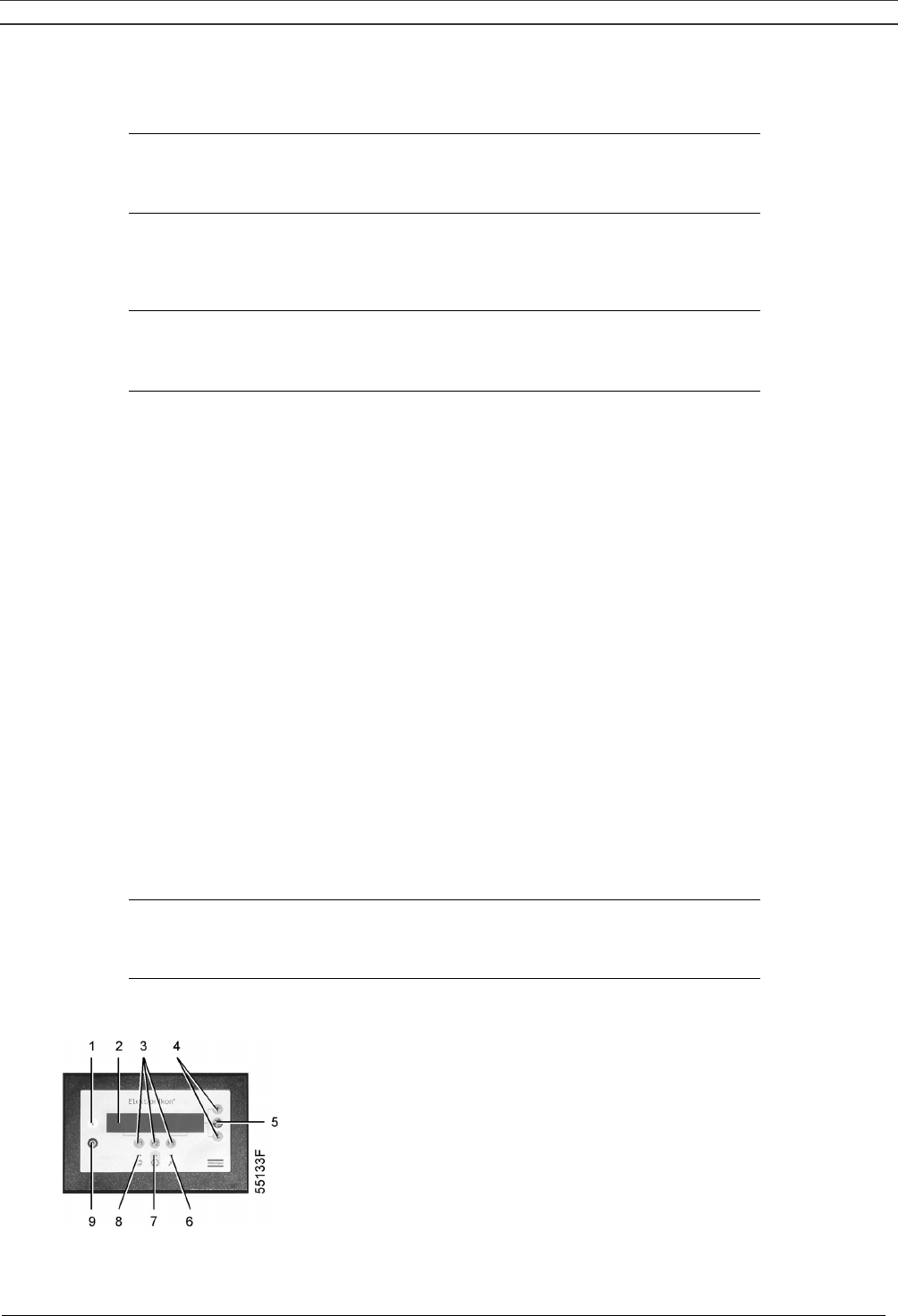
Instruction book
2920 1521 00 57
2. Use the ↓ key to scroll until the option "Clock function" is followed by a horizontal arrow. Press the
tabulator key (5), following screen appears:
Clock Function
Not activated
→
Menu Modify Delete
F1 F2 F3
3. Press the tabulator key (5), following screen appears:
Monday →
Tuesday
Wednesday
↓
Menu Delete
F1 F2 F3
4. Scroll through the display until "Saturday" is followed by a horizontal arrow. Press the tabulator
key (5). If necessary, scroll through the compressor start/stop/pressure band commands until the
command to be modified is followed by symbol ┤ on the screen. Press the key "Modify", the first
two digits of the command start blinking. Modify as required using the scroll keys, i.e. in the
example above change "18" into "17" using the ↓ key.
5. If necessary, press the tabulator key (5) to go to the next field to be modified, the minutes
indication and the start/stop/pressure band indication.
6. Press the key "Program" to program the new command or the key "Cancel" to quit without
reprogramming.
8.11.4 To add a command
Adding a command at the end of an existing list
1. Starting from the Main screen (see section 8.1.2):
- press the key "Menu" (F1)
- press the ↓ key until the option "Modify parameters" is followed by a horizontal arrow
- press the tabulator key (5) to activate the menu
2. Use the ↓ key to scroll until the option "Clock function" is followed by a horizontal arrow. Press the
tabulator key (5), following screen appears:
Clock Function
Not activated
→
Menu Modify Delete
F1 F2 F3
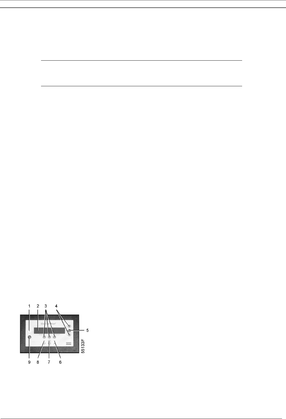
Instruction book
2920 1521 00 58
Suppose the command to stop the compressor at 18:00 must be added to the list of Monday:
- 06:15 start
- 06:15 pressure band 1
3. Press the tabulator key (5), following screen appears:
Monday →
Tuesday
Wednesday
↓
Menu Delete
F1 F2 F3
4. Scroll through the display until "Monday" is followed by a horizontal arrow. Press the tabulator key
(5). Scroll through the compressor start/stop/pressure band commands until the first empty
command line is indicated by symbol ┤ on the screen.
5. Press the key "Modify", the first two digits of the command start blinking. Enter "18:00 stop" using
the scroll keys ↓ or ↑ to modify a field and the tabulator key (5) to jump from one field to another.
6. Press the key "Program" to program the new command or the key "Cancel" to quit without
reprogramming.
Adding a command between two existing commands
1. Suppose the command 17:00 pressure band 2 must be added to following list:
- 06:00 start
- 06:00 pressure band 1
- 18:00 stop
2. The regulator does not allow to enter a new command which is situated timewise before the last
command in the list.
3. Scroll through the display until the command before which the new command must be entered is
followed by symbol ┤ (in the example above: 18:00 stop) and press the key "Modify". Change this
command to the new command (in the example above: 17:00 pressure band 2) and press the
"Program". Press the ↓ key, add the last command of the list (in the example above: 18:00 stop)
and press the key "Program".
8.11.5 To delete commands
1. Starting from the Main screen (see section 8.1.2):
- press the key "Menu" (F1)
- press the ↓ key until the option "Modify parameters" is followed by a horizontal arrow
- press the tabulator key (5) to activate the menu

Instruction book
2920 1521 00 59
2. Use the ↓ key to scroll until the option "Clock function" is followed by a horizontal arrow. Press the
tabulator key (5), following screen appears:
Clock Function
Not activated
→
Menu Modify Delete
F1 F2 F3
Deleting all commands
Press the key "Delete" (F3) in the screen above. A question to confirm the deleting operation will
appear.
Deleting all commands related to a specific day
Scroll through the display until the desired day is followed by a horizontal arrow. Press the key
"Delete" (F3). A question to confirm the deleting operation will appear.
Deleting a specific start/stop/pressure band command
Scroll through the display until the desired start, stop, pressure band 1 or pressure band 2 command
line is followed by symbol ┤. Press the key "Delete" (F3). A question to confirm the deleting operation
will appear.
8.12 Configuration menu
Function
To reprogram a number of parameters. See Fig. 8.1.
Procedure
1. Starting from the Main screen (see section 8.1.2):
- press the key "Menu" (F1)
- press the ↓ key until the option "Modify parameters" is followed by a horizontal arrow
- press the tabulator key (5) to activate the menu
2. Use the ↓ key to scroll until the option "Configuration" is followed by a horizontal arrow.
3. Press the tabulator key (5): The first option shown is "C.C.M" (Compressor Control Mode). If
another option is desired, scroll through the display (using ↓ or ↑ keys) until the option is followed
by symbol ┤.
4. In case of option "Time", the first line indicates the actual setting, e.g. 14:30 followed by symbol ┤.

Instruction book
2920 1521 00 60
5. If it is desired to modify the time, press the key "Modify". If not, press the key "Menu" to return to
the submenu.
6. After pressing the key "Modify", the first field (14) will blink. Modify the hours using the ↓ or ↑
keys. Then press the tabulator key (5) to go to the next field (i.e. 30). The setting of this field can
now be modified with the ↓ or ↑ keys.
7. The bottom line of the display will show two options:
- "Program" to program the new setting
- "Cancel" to cancel the new setting
8. Proceed in a similar way for the other parameters to be modified.
8.12.1 Programming compressor control modes
Compressor control modes
The compressor can be controlled locally, remotely or via a local area network (LAN – consult Atlas
Copco).
Procedure
1. Starting from the Main screen (see section 8.1.2):
- press the key "Menu" (F1)
- press the ↓ key until the option "Modify parameters" is followed by a horizontal arrow
- press the tabulator key (5) to activate the menu
2. Use the ↓ key to scroll until the option "Configuration" is followed by a horizontal arrow.
3. Press the tabulator key (5): The first option shown is "C.C.M." (Compressor Control Mode),
followed by the actual setting. Following screen is shown:
C.C.M. Local Control ┤
Pressure Band Selected Pressure Band 1
Node ID 31 ↓
Menu Modify
F1 F2 F3
Fig. 8.18 Compressor control mode menu
4. Press the key "Modify" and use ↓ or ↑ keys to select the desired control mode. Press the
"Program" key to program or the "Cancel" key to cancel the modification.
8.13 Service menu
Function
- To reset the service plans which are carried out.
- To check for both the next service plans to be carried out and to find which service plans were
carried out previously.
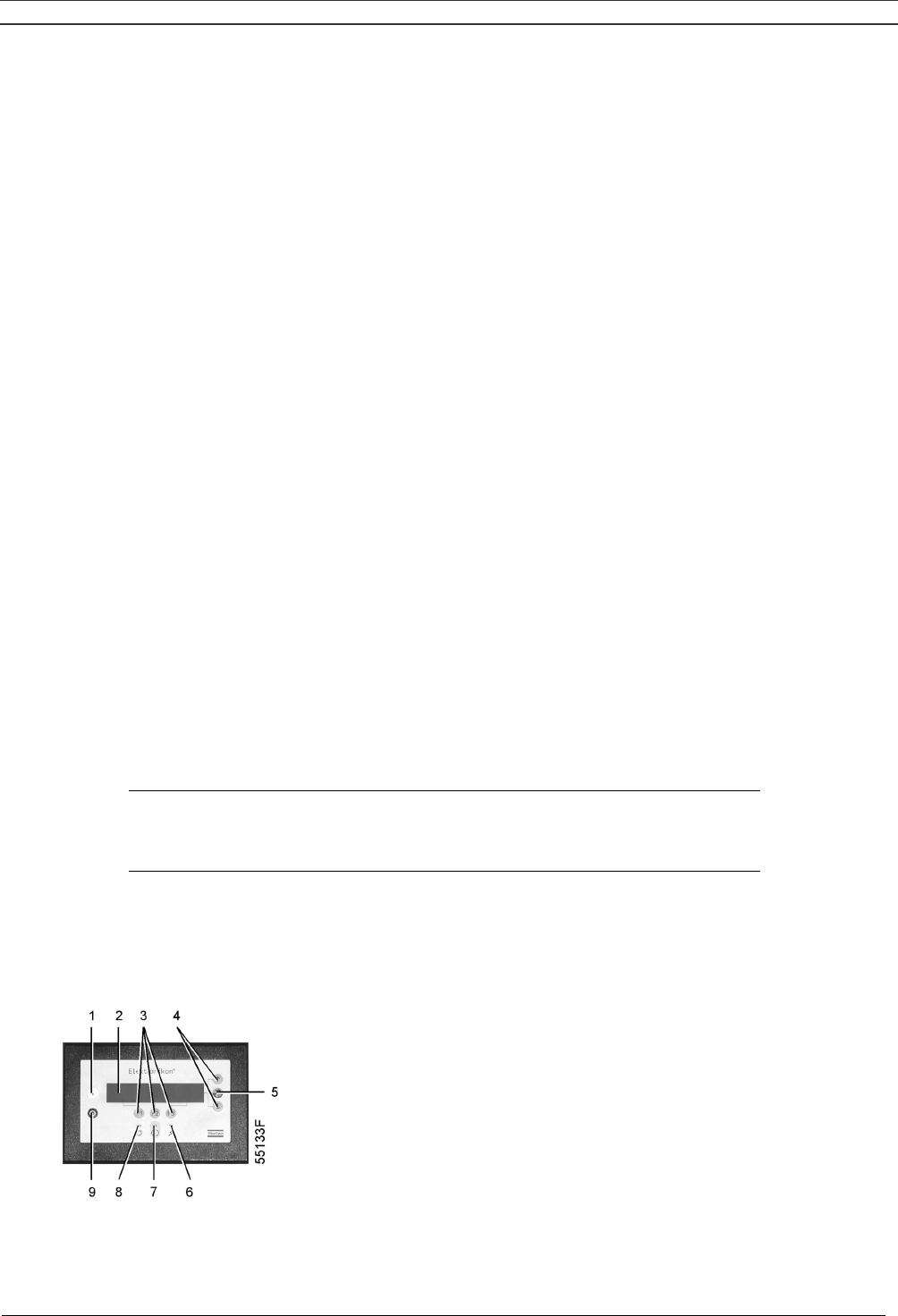
Instruction book
2920 1521 00 61
Service plans
- Contact your Atlas Copco customer centre for the service actions related to these plans.
- Consult section 8.10 if any modification to the intervals should be required.
When the service plan interval is reached, a message will appear on the screen. See section 8.3.
Example
Programmed service plan intervals
Service plans Intervals
Service plan I Each 2500 running hours
Service plan A Each 5000 running hours
Service plan B Each 10000 running hours
Service plan D Each 20000 running hours
Resulting service actions to be carried out
Service actions according to At
Service plan I 2500 running hours
Service plan I and A 5000 running hours
Service plan I, A and B 10000 running hours
Service plan I, A, B and D 20000 running hours
… …
Procedure
1. Starting from the Main screen (see section 8.1.2):
- press the key "Menu" (F1)
- press the ↓ key until the option "Service" is followed by a horizontal arrow
- press the tabulator key (5) to activate the menu
2. A screen similar to the one below appears:
Service Timer
Running Hours →
7971 hrs
↓
Menu
F1 F2 F3
Fig. 8.19 Service menu, typical example
The screen shows that the total compressor running time is 7971 hrs.

Instruction book
2920 1521 00 62
3. Press the tabulator key (5):
Next Timer
Level ABI
10000 hrs
↓
Back Reset
F1 F2 F3
Fig. 8.20 Service menu, typical example
The screen shows that the next service plans to be carried out are plans A, B and I and that these
plans are to be carried out each 10000 running hours.
4. Press the ↓ key to find which service plans were carried out previously:
Previous Timer ↑
Level AI
5008 hrs
Back
F1 F2 F3
Fig. 8.21 Service menu, typical example
The screen shows that service plans A and I were carried out at 5008 running hours.
5. Stop the compressor, switch off the voltage and carry out the service operations related to plans
A, B and I.
6. Switch on the voltage and scroll to the service screen shown in Fig. 8.20. Press the "Reset"
button (F3) to reset the timer. Confirm the question for resetting.
Notes
- The "Reset" button only appears when the next Timer level is almost reached (from 400
running hours before elapsing of the service plan interval).
- After pressing the ↓ key in Fig. 8.19, the Life time hours are shown (i.e. the number of hours
elapsed since initial programming ex-factory). This counter is not taken into account.
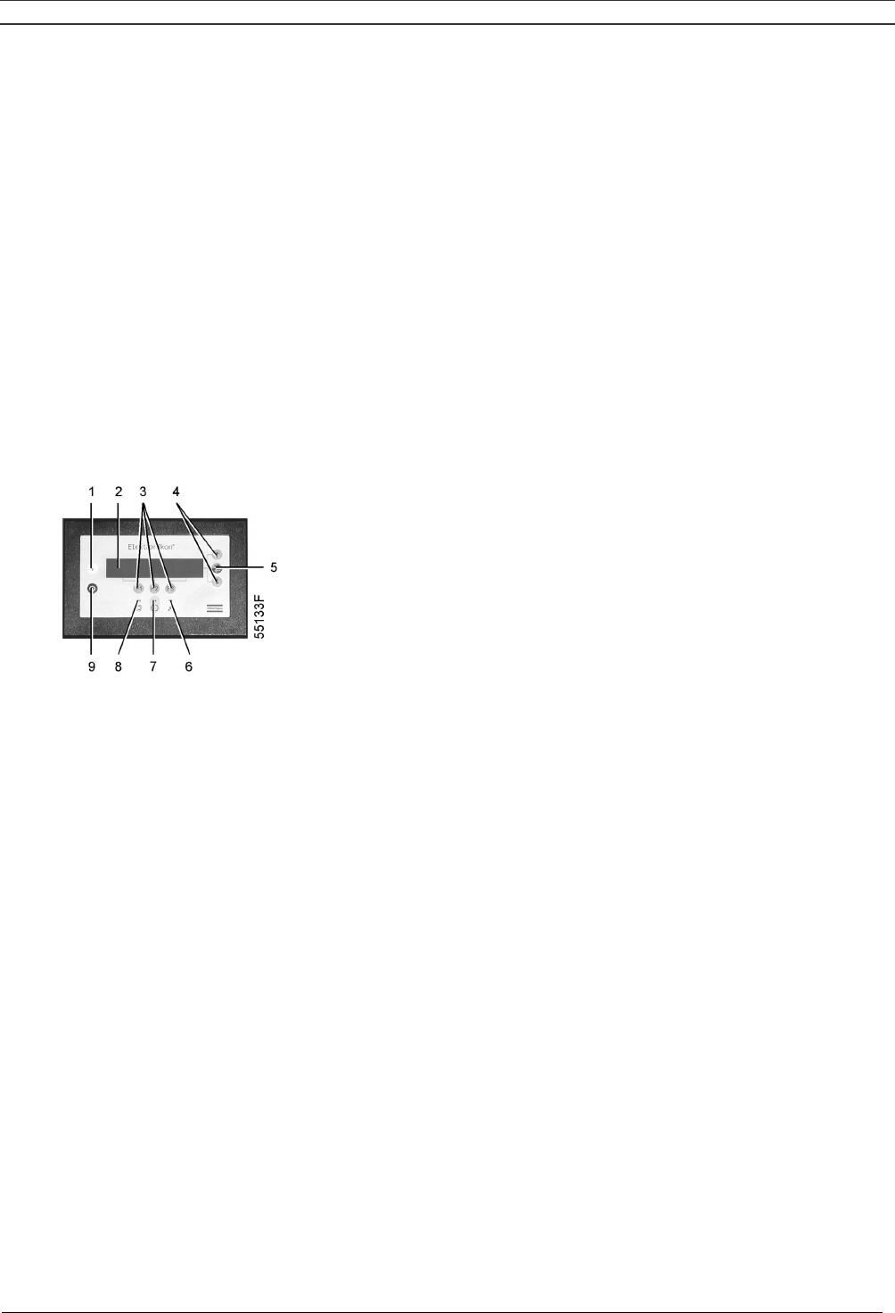
Instruction book
2920 1521 00 63
8.14 Saved data menu
Function
To call up some compressor data saved by the regulator. These data are:
- Last shut-down data
- Last emergency stop data
Procedure
1. Starting from the Main screen (see section 8.1.2):
- press the key "Menu" (F1)
- press the ↓ key until the option "Saved data" is followed by a horizontal arrow
- press the tabulator key (5) to activate the menu
2. The list of last shut-down cases is shown.
3. Scroll through the items to select the desired shut-down item.
4. Press the tabulator key (5) to find the date, time and other data reflecting the status of the
compressor at the last shut-down occurred.
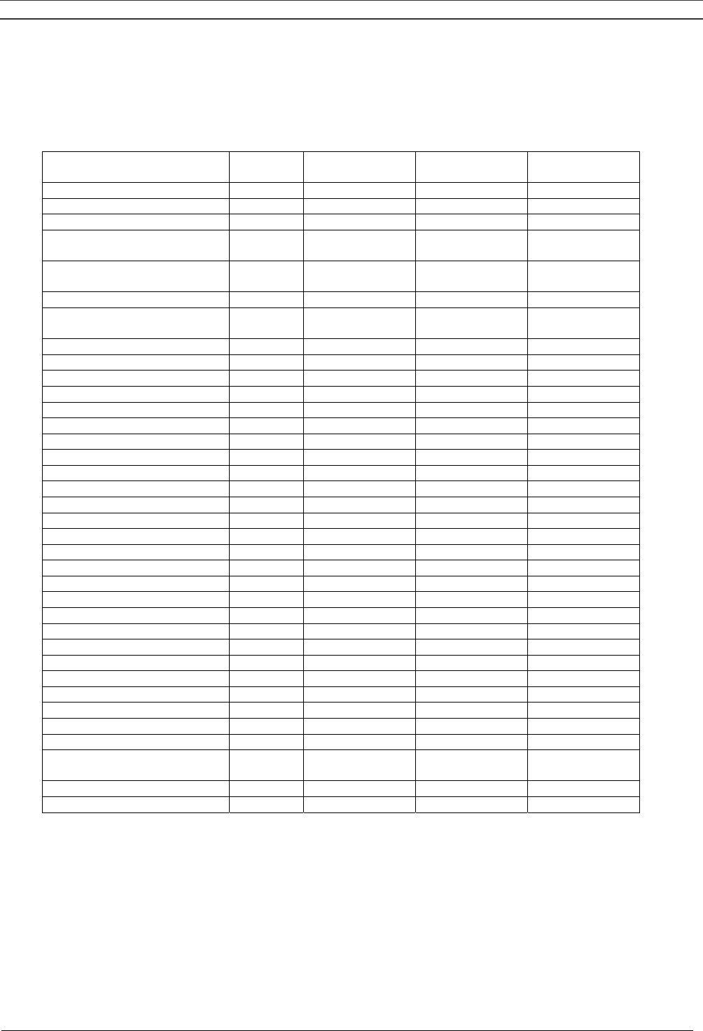
Instruction book
2920 1521 00 64
8.15 Programmable settings
8.15.1 Regulation settings
Minimum
setting
Nominal
setting
Maximum
setting
Number of motor starts starts/day 240 720 720
Minimum stop time 1) sec 5 5 30
Stop between 2 compressor
modules sec 2 2 5
Start between 2 compressor
modules sec 2 2 10
Power recovery time 3) sec 10 10 3600
Delay at restarting after
power recovery 3) sec 0 0 1200
Minimum pressure 2)
8 bar Pack bar(e) 4 7 7.9
8 bar Full-Feature bar(e) 4 6.8 7.7
10 bar Pack bar(e) 4 9 9.9
10 bar Full-Feature bar(e) 4 8.8 9.7
100 psi Pack bar(e) 4 7 7.9
100 psi Full-Feature bar(e) 4 6.8 7.7
125 psi Pack bar(e) 4 8.1 9
125 psi Full-Feature bar(e) 4 7.75 8.8
145 psi Pack bar(e) 4 9 9.9
145 psi Full-Feature bar(e) 4 8.8 9.7
Maximum pressure 2)
8 bar Pack bar(e) 4.1 8 8
8 bar Full-Feature bar(e) 4.1 7.8 7.8
10 bar Pack bar(e) 4.1 10 10
10 bar Full-Feature bar(e) 4.1 9.8 9.8
100 psi Pack bar(e) 4.1 8 8
100 psi Full-Feature bar(e) 4.1 7.8 7.8
125 psi Pack bar(e) 4.1 9.1 9.1
125 psi Full-Feature bar(e) 4.1 8.9 8.9
145 psi Pack bar(e) 4.1 10 10
145 psi Full-Feature bar(e) 4.1 9.8 9.8
For Full-Feature also 4)
Dewpoint warning
temperature °C 3 15 40
Delay at signal 5) sec 0 3 10
Delay at starting 6) sec 0 255 255

Instruction book
2920 1521 00 65
8.15.2 Service settings
Minimum
setting
Nominal
setting
Maximum
setting
Service Plan I hr 2000 2500 2500
Service Plan A hr 4000 5000 5000
Service Plan B hr 8000 10000 10000
Service Plan D hr 16000 20000 20000
Footnotes chapter 8
1) Once the compressor module is automatically stopped, it will remain stopped for the minimum
stop time, whatever happens with the air net pressure.
2) The regulator does not accept illogical settings, e.g. if the stopping pressure is programmed at 7.0
bar(e), the maximum limit for the starting pressure changes into 6.9 bar(e). The recommended
minimum pressure difference between starting and stopping is 0.6 bar.
3) Is only accessible if the automatic restart function is activated. The power recovery time (the
period within which the voltage must be restored to have an automatic restart) can be set between
10 and 3600 seconds. A delay at restarting can also be programmed, allowing e.g. compressors
to be restarted one after the other. To activate the automatic restart function, consult Atlas Copco.
4) Full-Feature version is the Pack version with integrated air dryer.
5) Is the time period during which the warning signal must exist before the warning message
appears.
6) Is the time period during which the warning signal is ignored after starting to allow the dryer to
reach the dewpoint temperature.
9 CONVERSION LIST OF SI UNITS INTO US/BRITISH UNITS
1 bar = 14.504 psi
1 g = 0.0353 oz
1 kg = 2.205 lb
1 km/h = 0.621 mile/h
1 kW = 1.341 hp (UK and US)
1 l = 0.264 US gal
1 l = 0.220 Imp (UK gal)
1 l = 0.0353 cu.ft
1 m = 3.281 ft
1 mm = 0.0394 in
1 m3/min = 35.315 cfm
1 mbar = 0.401 in water column
1 N = 0.225 lbf
1 Nm = 0.738 lbf.ft
X °C = (1.8X + 32) °F 1)
Footnotes chapter 9
1) A temperature difference of 1 °C = a temperature difference of 1.8 °F
Product: SF1-4 Skid and Tank-Mounted
SF6-8 Twin
SF6-15 Multi
Instructions for use of air receiver
1 This vessel can contain pressurized air; be ware of its potential danger in case of misuse.
2 The vessel shall only be used to store compressed air and shall not be subject to rapid fluctuation
of pressure.
3 This vessel shall only be used within the pressure and temperature limits stated on the data plate
and the testing report, which should be kept with care.
4 No alterations shall be made to this vessel by welding, drilling or any other mechanical methods
without written permission of the manufacturer.
5 Make sure that the vessel is complete with suitable and appropriate safety and control fittings and
replace them with new Atlas Copco ones (consult the parts list) if necessary.
The safety valve must be fitted directly to the vessel and the discharge capacity should be higher
than the air intake of the compressor. It should be set and leaded at a pressure of 11 bar.
6 Do not store the vessel near heating sources and inflammable substances and avoid storage of
the vessel in badly ventilated rooms.
7 Use vibration dampers to reduce the vibration during operation, which can cause failure.
Do not mount the vessel to the ground or fixed structures.
8 Drain condensate from the vessel daily, to prevent corrosion inside the vessel. During
maintenance, every 12 months, check for the presence of internal corrosion. Check more
frequently if the vessel is used with an oil-free compressor or when it is used in adverse conditions
(high humidity, presence of acids).
If corrosion is present, the minimum thickness is 3.45 mm for the shell and 3.4 mm for the head.
The legal checks have to be made in accordance with the local laws and rules where the vessel is
used.
PED (Pressure Equipment Directive)
Components subject to 97/23/EC Pressure Equipment Directive
Components subject to 97/23/EC Pressure Equipment Directive greater than or equal to Category II.
Part number Description PED Class
0830 1007 75 Safety valve IV
0830 1007 76 Safety valve IV
0830 1007 68 Safety valve IV
Overall Rating
The compressors are conform to PED smaller than or equal to category I.

Instruction book
2920 1521 00 67
Notes:

Instruction book
2920 1521 00 68
Notes:

Compressor type: . . . . . . . . . . . . . . . . . . . . . . . . . . . . . . . . . . . . . . . . Unit serial No. compressor: . . . . . . . . . . . . . . . . . . . . . . . . . . . . . . . . . . . .
Air dryer type: . . . . . . . . . . . . . . . . . . . . . . . . . . . . . . . . . . . . . . . . . . Unit serial No. dryer: . . . . . . . . . . . . . . . . . . . . . . . . . . . . . . . . . . . . . . . . .
Motor type: . . . . . . . . . . . . . . . . . . . . . . . . . . . . . . . . . . . . . . . . . . . . . Motor serial No.: . . . . . . . . . . . . . . . . . . . . . . . . . . . . . . . . . . . . . . . . . . . .
Delivery date: . . . . . . . . . . . . . . . . . . . . . . . . . . . . . . . . . . . . . . . . . . . First start-up date: . . . . . . . . . . . . . . . . . . . . . . . . . . . . . . . . . . . . . . . . . . .
Service Plan: . . . . . . . . . . . . . . . . . . . . . . . . . . . . . . . . . . . . . . . . . . . . Owner's machine No.: . . . . . . . . . . . . . . . . . . . . . . . . . . . . . . . . . . . . . . . .
Selected lubricants
Compressor: . . . . . . . . . . . . . . . . . . . . . . . . . . . . . . . . . . . . . . . . . . . . Capacity: . . . . . . . . . . . . . . . . . . . . . . . . . . . . . . . . . . . . . . . . . . . . . . . . . .
Bearing grease type, electric motor: . . . . . . . . . . . . . . . . . . . . . . . . .
Dryer gearbox . . . . . . . . . . . . . . . . . . . . . . . . . . . . . . . . . . . . . . . . . . . Capacity . . . . . . . . . . . . . . . . . . . . . . . . . . . . . . . . . . . . . . . . . . . . . . . . . . .
Printed Matter Nos.
Atlas Copco compressor instruction book: . . . . . . . . . . . . . . . . . . . . Atlas Copco air dryer instruction book: . . . . . . . . . . . . . . . . . . . . . . . . . .
Atlas Copco compressor parts list: . . . . . . . . . . . . . . . . . . . . . . . . . . Atlas Copco air dryer parts list: . . . . . . . . . . . . . . . . . . . . . . . . . . . . . . . .
Atlas Copco logbook: . . . . . . . . . . . . . . . . . . . . . . . . . . . . . . . . . . . . . . . . . . . . . . . . . . . . . . . . . . . . . . . . . . . . . . . . . . . . . . . . . . . . . . . . . . . . . . . . . . . .
Local Atlas Copco Representative
Name: . . . . . . . . . . . . . . . . . . . . . . . . . . . . . . . . . . . . . . . . . . . . . . . . . . . . . . . . . . . . . . . . . . . . . . . . . . . . . . . . . . . . . . . . . . . . . . . . . . . . . . . . . . . . . . .
Address: . . . . . . . . . . . . . . . . . . . . . . . . . . . . . . . . . . . . . . . . . . . . . . . . . . . . . . . . . . . . . . . . . . . . . . . . . . . . . . . . . . . . . . . . . . . . . . . . . . . . . . . . . . . . . .
Telephone: . . . . . . . . . . . . . . . . . . . . . . . . . . . . . . . . . . . Contact persons: Service: . . . . . . . . . . . . . . . . . . . . . . . . . . . . . . . . . . . . . . . . .
Telex:. . . . . . . . . . . . . . . . . . . . . . . . . . . . . . . . . . . . . . Parts: . . . . . . . . . . . . . . . . . . . . . . . . . . . . . . . . . . . . . . . . . . .
E-mail . . . . . . . . . . . . . . . . . . . . . . . . . . . . . . . . . . . . . . . . . . . . . . . . . . . . . . . . . . . . . . . . . . . . . . . . . . . . . . . . . . . . . . . . . . . . . . . . . . . . . . . . . . . . . . .
SAFETY PRECAUTIONS
T o be r ead attentively and acted accordingly befor e installing, operating or r epairing the unit.
These recommendations apply to machinery processing or consuming air or inert gas. Processing of any other gas requires
additional safety precautions typical to the application which are not included herein.
If necessary , install a suction duct. Never obstruct the air inlet. Care
shall be taken to minimize the entry of moisture with the inlet air .
4. The aspirated air shall be free from flammable fumes or vapours,
e.g. paint solvents, that can lead to internal fire or explosion.
5. Air -cooled units shall be installed in such a way that an adequate
flow of cooling air is available and that the exhausted air does not
recirculate to the inlet.
6. Arrange the air intake so that loose clothing of people cannot be
sucked in.
7. Ensure that the dischar ge pipe from the compressor to the aftercooler ,
air dryer or air net is free to expand under heat and that it is not in
contact with or close to flammable material.
8. No external force may be exerted on the air outlet valve; the connected
pipe must be free of strain.
9. If remote control is installed, the unit shall bear an obvious sign
reading:
DANGER: This machine is r emotely controlled and may star t
without warning.
As a further safeguard, persons switching on remotely controlled
units shall take adequate precautions to ensure that there is no one
checking or working on the machine. T o this end, a suitable notice
shall be af fixed to the start equipment.
10. On units with automatic start-stop system, a sign stating "This
machine may start without warning" shall be attached near the
instrument panel.
11. In multiple compressor systems manual valves shall be installed to
isolate each compressor . Non-return valves (check valves) shall not
be relied upon for isolating pressure systems.
12. Never remove or tamper with the safety devices, guards or insulations
fitted on the unit. Every pressure vessel or auxiliary installed outside
the unit to contain air above atmospheric pressure shall be protected
by a pressure-relieving device or devices as required.
13. Pipework or other parts with a temperature in excess of 80 degrees
celsius and which may be accidentally touched by personnel in normal
operation shall be guarded or insulated. Other high-temperature
pipework shall be clearly marked.
OWNERSHIP DATA
In addition to normal safety rules which should be observed with stationary
air compressors and equipment, the following safety directions and
precautions are of special importance.
When operating this unit, the operator must employ safe working practices
and observe all related local work safety requirements and ordinances.
The owner is responsible for maintaining the unit in a safe operating
condition. Parts and accessories shall be replaced if unsuitable for safe
operation.
Installation, operation, maintenance and repair shall only be performed
by authorized, trained, competent personnel.
Normal ratings (pressures, temperatures, time settings, etc.) shall be
durably marked.
Any modification on the compressor or air dryer shall only be performed
in agreement with Atlas Copco and under supervision of authorized,
competent personnel.
If any statement in this book, especially with regard to safety , does not
comply with local legislation, the stricter of the two shall apply.
These precautions are general and cover several machine types and
equipment; hence some statements may not apply to the unit(s) described
in this book.
Installation
Apart from general engineering practice in conformity with the local
safety regulations, the following directives are specially stressed:
1.A compressor or air dryer shall be lifted only with adequate equipment
in conformity with local safety rules.
Loose or pivoting parts shall be securely fastened before lifting. It is
strictly forbidden to dwell or stay in the risk zone under a lifted load.
Lifting acceleration and retardation shall be kept within safe limits.
W ear a safety helmet when working in the area of overhead or lifting
equipment.
2. Any blanking flanges, plugs, caps and desiccant bags shall be
removed before connecting up the pipes. Distribution pipes and
connections shall be of correct size and suitable for the working
pressure.
3. Place the unit where the ambient air is as cool and clean as possible.
2920 1377 03 1/2 (continued on inside of cover)
14. If the ground is not level or can be subject to variable inclination,
consult Atlas Copco.
15. The electrical connections shall correspond to the local codes. The
units shall be grounded and protected against short circuits by fuses.
Operation
1. Air hoses shall be of correct size and suitable for the working pressure.
Never use frayed, damaged or deteriorated hoses. Use only the correct
type and size of hose end fittings and connections. When blowing
through a hose or air line, ensure that the open end is held securely .
A free end will whip and may cause injury. Make sure that a hose is
fully depressurized before disconnecting it.
Never play with compressed air . Do not apply it to your skin or
direct an air stream at people. Never use it to clean dirt from your
clothes. When using it to clean equipment, do so with extreme caution
and use eye protection.
2. The compressor is not considered as capable of producing air of
breathing quality . For breathing air quality , the compressed air must
be adequately purified according to local legislation and standards.
3. Never operate the units when there is a possibility of taking in
flammable or toxic fumes.
4. Never operate the units at pressures below or in excess of their limit
ratings as indicated on the Principal Data sheet.
5. Keep all bodywork doors shut during operation. The doors may be
opened for short periods only, e.g. to carry out checks. W ear ear
protectors when opening a door .
6. People staying in environments or rooms where the sound pressure
level reaches or exceeds 90 dB(A) shall wear ear protectors.
7. Periodically check that:
a. All guards are in place and securely fastened
b. All hoses and/or pipes inside the unit are in good condition, secure
and not rubbing
c. There are no leaks
d. All fasteners are tight
e. All electrical leads are secure and in good order
f. Safety valves and other pressure-relief devices are not obstructed
by dirt or paint
g. Air outlet valve and air net, i.e. pipes, couplings, manifolds,
valves, hoses, etc. are in good repair , free of wear or abuse
8. If warm cooling air from compressors is used in air heating systems,
e.g. to warm up a workroom, take precautions against air pollution
and possible contamination of the breathing air .
9. Do not remove any of, or tamper with, the sound-damping material.
Maintenance
Maintenance and repair work shall only be carried out under supervision
of someone qualified for the job.
1. Use only the correct tools for maintenance and repair work.
2. Use only genuine spare parts.
3. All maintenance work, other than routine attention, shall only be
undertaken when the unit is stopped, the main power supply is
switched of f and the machine has cooled down. T ake positive
precaution to ensure that the unit cannot be started inadvertently .
In addition, a warning sign bearing a legend such as "work in
pr ogr ess; do not star t" shall be attached to the starting equipment.
4. Before removing any pressurized component, ef fectively isolate the
unit from all sources of pressure and relieve the entire system of
pressure.
5. Never use flammable solvents or carbon tetrachloride for cleaning
parts. T ake safety precautions against toxic vapours of cleaning
liquids.
6. Scrupulously observe cleanliness during maintenance and repair.
Keep dirt away by covering the parts and exposed openings with a
clean cloth, paper or tape.
7. Never weld or perform any operation involving heat near the oil
system. Oil tanks must be completely pur ged, e.g. by steam-cleaning,
before carrying out such operations.
Never weld on, or in any way modify, pressure vessels.
Whenever there is an indication or any suspicion that an internal
part of a machine is overheated, the machine shall be stopped but no
inspection covers shall be opened before suf ficient cooling time
has elapsed; this to avoid the risk of spontaneous ignition of the oil
vapour when air is admitted.
Never use a light source with open flame for inspecting the interior
of a machine, pressure vessel, etc.
8. Make sure that no tools, loose parts or rags are left in or on the unit.
9. Before clearing the unit for use after maintenance or overhaul, check
that operating pressures, temperatures and time settings are correct
and that the control and shut-down devices function correctly. If
removed, check that the coupling guard of the compressor drive shaft
has been reinstalled.
10. Every time the separator element is renewed, examine the dischar ge
pipe and the inside of the oil separator vessel for carbon deposits; if
excessive, the deposits should be removed.
11. Protect the motor , air filter, electrical and regulating components,
etc. to prevent moisture from entering them, e.g. when steam-cleaning.
12. Make sure that all sound-damping material, e.g. on the bodywork
and in the air inlet and outlet systems of the compressor , is in good
condition. If damaged, replace it by genuine Atlas Copco material
to prevent the sound pressure level from increasing.
13. Never use caustic solvents which can damage materials of the air
net, e.g. polycarbonate bowls.
14. The following safety precautions are stressed when handling
refrigerant:
a. Never inhale refrigerant vapours. Check that the working area
is adequately ventilated; if required, use breathing protection.
b. Always wear special gloves. In case of refrigerant contact with
the skin, rinse the skin with water . If liquid refrigerant contacts
the skin through clothing, never tear of f or remove the latter;
flush abundantly with fresh water over the clothing until all
refrigerant is flushed away; then seek medical first aid.
c. Always wear safety glasses.
15. Protect hands to avoid injury from hot machine parts, e.g. during
draining of oil.
Note: W ith stationary machine units driven by an internal combustion
engine, allowance has to be made for extra safety precautions, e.g. spark
arrestors, fuelling care, etc. Consult Atlas Copco.
All r esponsibility for any damage or injur y r esulting fr om neglecting
these pr ecautions, or by non-observance of ordinar y caution and due
car e r equir ed in handling, operating, maintenance or r epair, even if
not expressly mentioned in this book, will be disclaimed by Atlas
Copco.
SAFETY PRECAUTIONS (continued)
2920 1377 03 2/2
