Attenti US WMTD3418 ANKLE WRIST WORN GPS TRACKING DEVICE User Manual WMTD Users Manual
3M Electronic Monitoring ANKLE WRIST WORN GPS TRACKING DEVICE WMTD Users Manual
UserManual.wiki
>
Attenti US
>
WMTD3418 User Manual
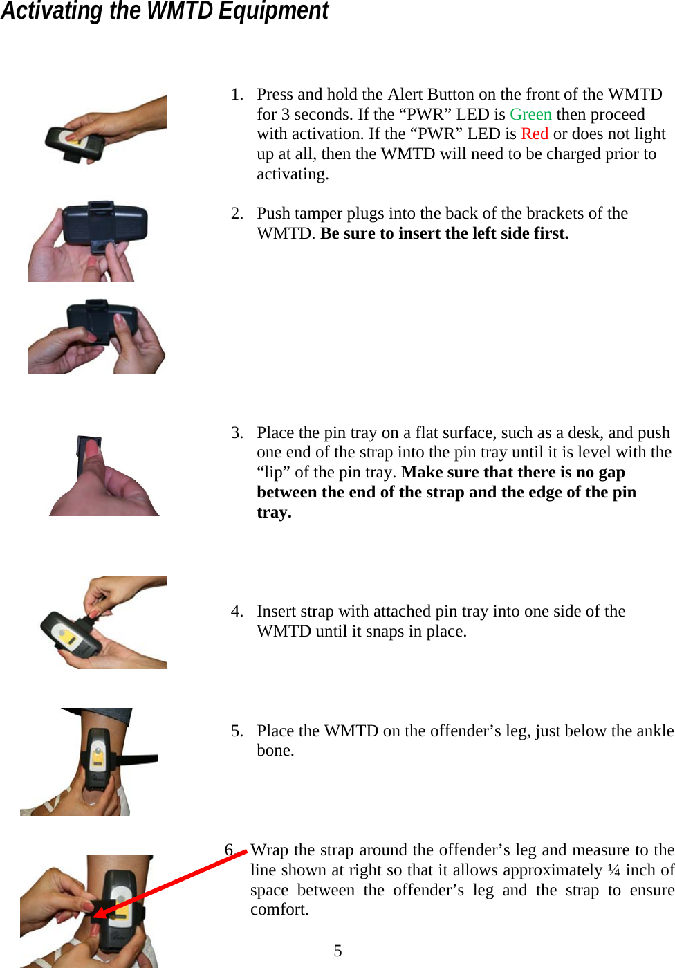
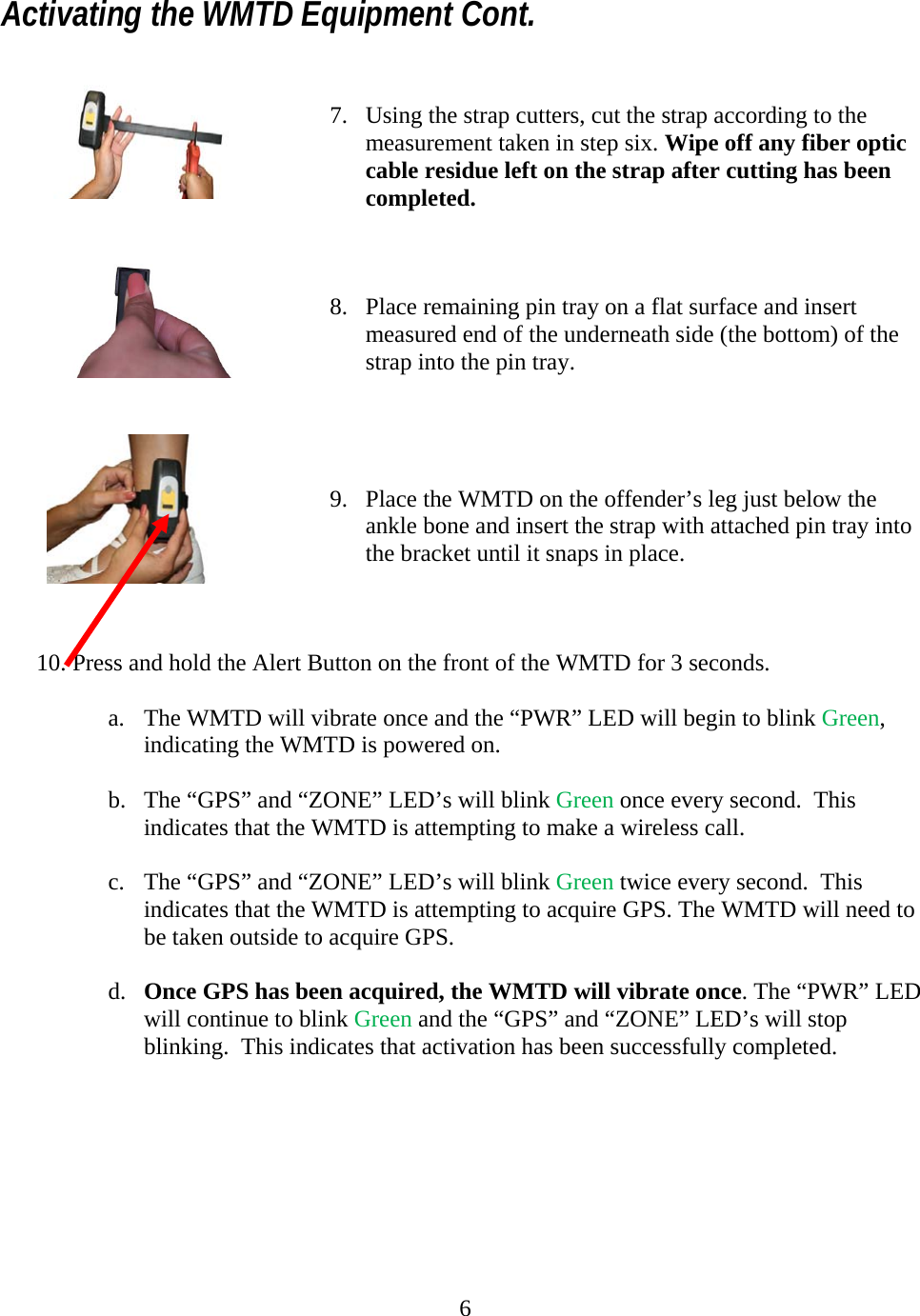
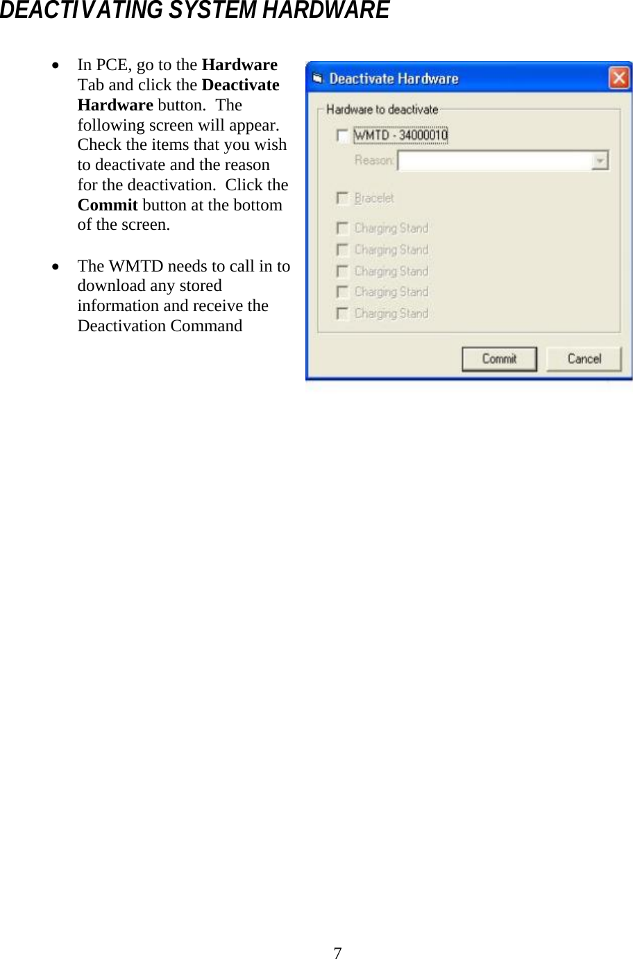
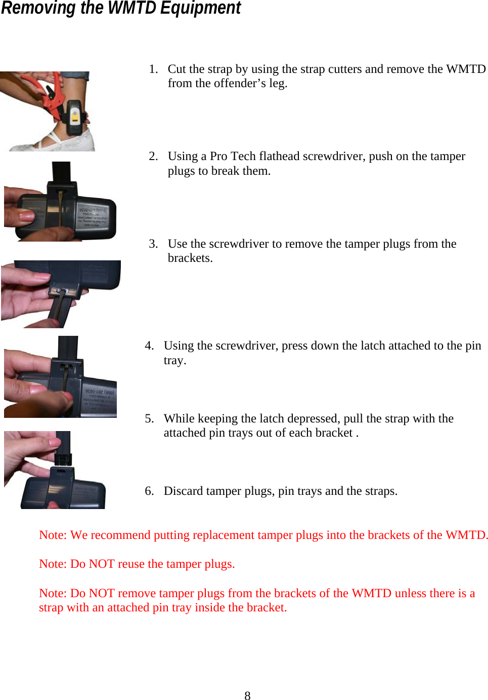
Users Manual
Navigation menu
Upload a User Manual
Namespaces
Wiki Guide
HTML
PDF
Info
Views
User Manual
Discussion / Help
Navigation