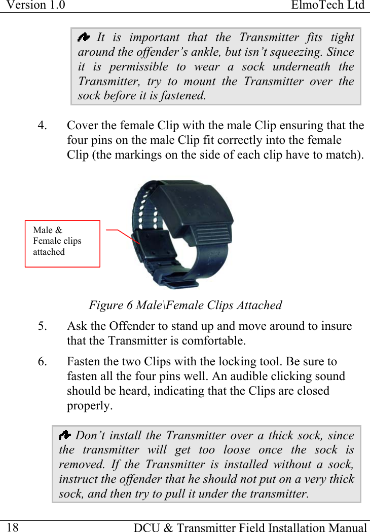
Attenti DCU-2010 Data collection unit, DCU 2010 User Manual EMS2000i HMRU Transmitter Installation Manual

3M Electronic Monitoring, Inc. Data collection unit, DCU 2010 EMS2000i HMRU Transmitter Installation Manual

User Manual

       DCU 2010  INSTALLLATION  MANUAL  Version 1.0 April 2002
ElmoTech Ltd  Version 1.0                                                                           DCU & Transmitter Field Installation Manual    1  Prepared by: Elmo-Tech Ltd. Corporate Headquarters 2 Ha-Barzel St. P.O. Box 13236 Ramat Ha-Chayal 61132 Tel Aviv Israel Tel: 03 – 6478871 Fax: 03 – 6478872 Visit us at: www.elmotech.com        © 2002, Elmo Tech Ltd. All rights reserved. No part of this publication may be reproduced, stored in a retrieval system, or transmitted in any form or by any means, electronic, mechanical, photocopying, recording or otherwise, for purpose other than the user’s manual, without prior permission of Elmo Tech Ltd.   NO WARRANTY The technical documentation is being delivered AS-IS, and ElmoTech Ltd. makes no warranty as to its accuracy or use. Any use of the technical documentation or the information contained therein is at risk of the user. Documentation may include technical or other inaccuracies or typographical errors. ElmoTech Ltd. Reserves the right to make change without prior notice.
Version 1.0  ElmoTech Ltd    DCU & Transmitter Field Installation Manual  2
ElmoTech Ltd  Version 1.0                                                                           DCU & Transmitter Field Installation Manual    3  TABLE OF CONTENTS  Section Page  THE MONITOR CENTER/ PROBATION AGENCY ..................7 EQUIPMENT .......................................................................................8 THE OFFENDER’S PREMISES......................................................9 MONITORING SYSTEM LOCATION......................................................9 INSTALLING THE DCU UNIT............................................................10 Downloading the Curfew Schedule ............................................12 INSTALLING THE TRANSMITTER.......................................................14 Calibrating the Transmitter........................................................14 Attaching the Transmitter...........................................................16 DCU Range Setting ....................................................................19 DAILY OPERATING INSTRUCTIONS.......................................23 INCOMING CALLS ............................................................................23 Accepting an incoming call ........................................................23 OUTGOING CALLS ...........................................................................24 Performing an outgoing call.......................................................24 GENERAL RULES FOR THE OFFENDER..............................................25 REMOVING THE MONITORING SYSTEM..............................27 INITIATING AN END OF SERVICE ......................................................27 DISCONNECTING AND PACKING THE DCU UNIT..............................27 REMOVING THE TRANSMITTER ........................................................28 DISCONNECTING THE TRANSMITTER ...............................................29
Version 1.0  ElmoTech Ltd    DCU & Transmitter Field Installation Manual  4TRANSMITTER CLEANING INSTRUCTIONS ........................31 CLEANING THE TRANSMITTER:........................................................31 TRANSMITTER STRAP REPLACEMENT ................................33 REASONS FOR STRAP REPLACEMENT...............................................33 EQUIPMENT NEEDED FOR STRAP REPLACEMENT .............................34 REPLACING THE TRANSMITTER STRAPS...........................................34 FCC NOTICES .................................................................................36 DCU FCC NOTICES ........................................................................36 DCU CUSTOMER INFORMATION......................................................37 TRANSMITTER FCC NOTICES ..........................................................39
ElmoTech Ltd  Version 1.0                                                                           DCU & Transmitter Field Installation Manual    5  LIST OF FIGURES  Figure Page  FIGURE 1 IDEAL DCU LOCATION..........................................................9 FIGURE 2 DIAGRAMMATIC VIEW OF A DCU........................................11 FIGURE 3 CALIBRATING THE TRANSMITTER ........................................15 FIGURE 4 ATTACHING THE TRANSMITTER ...........................................17 FIGURE 5 PROTRUDING SIDE OF TRANSMITTER DIRECTED UPWARDS...17 FIGURE 6 MALE\FEMALE CLIPS ATTACHED ........................................18 FIGURE 7 DISCONNECTING THE TRANSMITTER....................................29
Version 1.0  ElmoTech Ltd    DCU & Transmitter Field Installation Manual  6
ElmoTech Ltd  Version 1.0                                                                           THE MONITOR CENTER/ PROBATION AGENCY At the Monitor Center/Probation Agency: 1.  Enter the Offender’s data in the monitoring application. This can be done well in advance, even before the actual equipment is allocated and installed.  2.  Enter the following equipment data in the monitoring application.  •  DCU Serial No. - Check that the number entered matches the number on the DCU unit. •  Transmitter Serial No. - Check that the number entered matches the number on the Transmitter.  The DCU and Transmitter Serial numbers are visible on the back of each unit. DCU & Transmitter Field Installation Manual    7
Version 1.0  ElmoTech Ltd  Equipment Check that you have all the required equipment: •  DCU unit and power adapter •  Transmitter •  Electronic key •  Locking device •  Strap holder •  Strap clips (male and female) •  Screwdriver (to open a clip if necessary). It is recommended to use a 5 mm flat head screwdriver.    It is always advisable to bring an extra set of strap clips to cater for the event in which the first set may be accidentally damaged during the installation.       DCU & Transmitter Field Installation Manual  8
ElmoTech Ltd  Version 1.0                                                                           THE OFFENDER’S PREMISES Monitoring System Location  In order to install the Monitoring System, you will need to find the best location for the DCU unit. The ideal place for the DCU unit is in the center of the house, 3 feet off the ground and at least 1 foot away from the wall.   Figure 1 Ideal DCU Location DCU & Transmitter Field Installation Manual    9
Version 1.0  ElmoTech Ltd    DCU & Transmitter Field Installation Manual  10The DCU unit should be in an open area away from other electrical appliances (e.g. personal computers, laptops) or any metal objects. Installing the DCU Unit In order to install the DCU unit: 1.  Plug the appropriate end of the power adapter cord into the 12VDC socket at the back of the DCU unit.  2.  Plug the power adapter into a wall power socket. The DCU unit makes an audible beeping sound and then runs through a series of built-in-tests to check that everything is in order. 3.  After completing the tests successfully the DCU unit beeps again and the two external LED’s, located at the rear of the DCU unit, are turned on. This indicates that the DCU unit is in working order. The LED indicators are: •  Left LED - indicates that power is connected •  Right LED - indicates that the DCU unit has registered to a telephone network (network registration may take up to one minute after built-in-test completion).
ElmoTech Ltd  Version 1.0                                                                           DCU & Transmitter Field Installation Manual    11  Figure 2 Diagrammatic View of a DCU  If, at the end of the start-up self test, audible beeping sounds are heard and all three LED’s flash for 10 seconds, it indicates one of the following possible failures: i Case open micro-switch malfunction. i Tilt sensor malfunction. i Range threshold values lost (maximum reception    range is used in this case).
Version 1.0  ElmoTech Ltd    DCU & Transmitter Field Installation Manual  12Downloading the Curfew Schedule Downloading Curfew Schedule data requires that the CMS (Central Monitoring System) telephones the Offender’s premises and transmits a series of signals to the DCU unit to allow it to monitor the Offender. After the DCU unit has been installed, perform the following: 1.  Verify that the DCU units right LED is not flashing (i.e. the line is not busy). 2.  Call the Monitoring Center personnel, using a mobile phone, and ask them to perform a download.  3.  Monitor the following download communication process directly from the DCU unit at the offender’s premises: •  The telephone line LED (right) on the DCU unit flashes. The flashing indicates that the DCU unit has made a call, to the central computer. The telephone line LED then returns to its steady state. •  After a short while the telephone line LED starts flashing for a second time. This indicates the DCU unit has made another call to the central computer. The telephone line LED then stops flashing. •  After another short wait the telephone line LED starts flashing for the third time. This indicates that the DCU unit has made its last call to the central computer. When the telephone line LED stops flashing, the DCU unit has received all the information it requires and the monitoring process begins.
ElmoTech Ltd  Version 1.0                                                                           4.  The Monitor Center personnel call back (optional) to confirm a successful download or to inform that the download failed and has to be performed again. If the download is successful, the following information is downloaded: •  Transmitter code •  The curfew schedule •  Schedule flexibility •  Left violation sensitivity •  Sanity calls intervals   If there are other Transmitters in the same area (for example, if the installation was done, in an office, where other offenders may be present), the DCU unit may receive a transmission from a source other than the intended Transmitter. The download, in this case, is rejected and another download will need to be initiated.   Only when the DCU unit receives three successful downloads from the correct Transmitter (the one attached to the Offender), it continues to monitor that specific Transmitter only.   DCU & Transmitter Field Installation Manual    13
Version 1.0  ElmoTech Ltd    DCU & Transmitter Field Installation Manual  14Installing the Transmitter The officer should bring the following equipment for a Transmitter installation: •  Transmitter •  Male and female strap Clips  •  Electronic key •  Strap holder  •  Locking tool •  Flat-head screwdriver Calibrating the Transmitter Before any installation, the Transmitter has to be turned-on and calibrated. After the DCU unit is connected and in monitoring mode, do the following: 1.  Stand close to the DCU unit in order to hear the audible confirmation of the Transmitter calibration. 2.  Hold the transmitter in your hand with the 4 metal pins (2 pairs, along the strap) pointing forward. 3.  Hold the Electronic Key in your other hand, with the black button pointing toward the open or free end of the strap.
ElmoTech Ltd  Version 1.0                                                                            Figure 3 Calibrating the Transmitter 4.  Press the Electronic Key down over one pair of metal pins (it does not matter which) with the two touch points on the Electronic Key matching the pair of metal pins on the Transmitter strap. Hold the Electronic key in this position while you do the next step.    5.  Press the red button on the Electronic Key down for one second; the red light turns steadily on for two (2) seconds. 6.  If the transmitter successfully receives the reset command, the red light, on the Electronic Key, will flash for two (2) seconds.  If the transmitter failed to receive the calibration command, the red light will turn off after the initial two (2) seconds on.   If the Electronic Key battery is low the red light will immediately flash for two (2) seconds, once the red button is pressed. (No command is sent to the Transmitter). DCU & Transmitter Field Installation Manual    15
Version 1.0  ElmoTech Ltd  7.  Place the Transmitter on its side on a non-metal table and wait 30 to 60 seconds, until audible beeping sounds are heard from the DCU unit. These beeps indicate that the Transmitter has successfully completed its Calibration process and is ready to be mounted on the offender.   If a number of Transmitters calibrated at the same time, it is important to wait for the final beeps to be sure that the calibration went OK. After the OK confirmation the next Transmitter can be calibrated. Attaching the Transmitter In order to attach the Transmitter to the Offender, do the following:  1.  Flip a strap holder over the short strap of the Transmitter. 2.  Attach the female Clip to the underside of the Transmitter’s short strap (to lie against the Offenders skin). Verify that the closed end of the clip fits with the edge of the strap. Make sure the silver line is visible.      DCU & Transmitter Field Installation Manual  16
ElmoTech Ltd  Version 1.0                                                                            Female clip SilverlineFigure 4 Attaching the Transmitter 3.  Wrap the Transmitter around the offender’s ankle at its narrowest point. Ensure that the protruding side of the Transmitter is directed upwards.  Figure 5 Protruding side of Transmitter directed upwards DCU & Transmitter Field Installation Manual    17
Version 1.0  ElmoTech Ltd    DCU & Transmitter Field Installation Manual  18 It is important that the Transmitter fits tight around the offender’s ankle, but isn’t squeezing. Since it is permissible to wear a sock underneath the Transmitter, try to mount the Transmitter over the sock before it is fastened.  4.  Cover the female Clip with the male Clip ensuring that the four pins on the male Clip fit correctly into the female Clip (the markings on the side of each clip have to match).                               Male & Female clips attached Figure 6 Male\Female Clips Attached  5.  Ask the Offender to stand up and move around to insure that the Transmitter is comfortable. 6.  Fasten the two Clips with the locking tool. Be sure to fasten all the four pins well. An audible clicking sound should be heard, indicating that the Clips are closed properly.  Don’t install the Transmitter over a thick sock, since the transmitter will get too loose once the sock is removed. If the Transmitter is installed without a sock, instruct the offender that he should not put on a very thick sock, and then try to pull it under the transmitter.
ElmoTech Ltd  Version 1.0                                                                           DCU & Transmitter Field Installation Manual    19  The Offender may wear a thin sock underneath and a thick sock over the Transmitter.                       DCU Range Setting DCU Range Setting is designed in order to create a limited free movement area. This ensures that Offender stays as close as possible to his\her premises and the immediate surrounding area.  Four range settings are available:  Short, Medium, Long and Maximum. To change the DCU range, a central computer command is required. In order to set and test the DCU reception range, do the following: 1.  Estimate the offender premises size and decide on the appropriate range setting for starting the range test. 2.  Phone the Monitor Center/Agency personnel and ask them, first, to select the appropriate range and then to initiate the range setting test. Once the range setting test has been initiated by the Monitor Center, the following occurs:  •  The Offender’s telephone rings approximately 2-3 times.  •  After the phone stops ringing, the telephone line LED (right) on the DCU unit flashes for a while and then returns to its steady state. •  After the telephone line LED on the DCU unit stops flashing, the middle LED blinks 3 times in quick
Version 1.0  ElmoTech Ltd  sequence accompanied by 3 audible beeping sounds. This means that range test has started.   The DCU unit will be in the range test mode for approximately 15 minutes, unless the Monitor Center/Agency terminates it manually. You can now escort the Offender around his/her premises in order to check that the range is sufficient, and to check for dead spots. 3.  Escort the offender to the following locations in his/her premises: •  Locations that are the most distant from the DCU unit. •  Locations behind large metal objects. •  Locations where the Offender spends long periods of time (e.g. bedroom, toilet, living room, etc.). •  Remote locations where the Offender is allowed to stay while at home (e.g. garage, cellar, yard, etc.). •  Any location that your experience and common sense suggests to be a viable location must be tested.  Don’t perform a range test in any locations where you don’t want the Offender to be (e.g. yard, garage, etc.). 4.  An assistant stands next to the DCU unit and observes the middle LED.  Every time the DCU unit receives a transmission from the PID (approximately every 20 seconds) the middle LED flashes 3 times in quick sequence.   DCU & Transmitter Field Installation Manual  20
ElmoTech Ltd  Version 1.0                                                                           5.  Wait for up to two minutes in each checked location.  During these two minutes four transmissions should be received from the PID.    If four transmissions are received before two minutes have elapsed, you can move with the Offender to the next location to be checked.  If less than four transmissions are received, phone the Monitor Center/ Agency and ask to change the range setting to a longer range.    If the range setting is already set at long range, relocate the DCU unit in order to get better coverage. 6.  After satisfactory testing of all relevant locations, ask the Monitor Center/Agency personnel to end the range test (manually). If the range is not sufficient, you have to ask the Monitor Center/Agency to perform a new ‘Start Range’ with a longer range and then re-test where the previous test failed.  7.  Upon ending the range test, the DCU unit makes an audible beeping sound to indicate range test completion.   As a precaution against accidentally leaving the DCU unit in the range-testing mode, the DCU unit automatically terminates the range test 15 minutes after initiation.  Therefore, if the range test lasts longer than 15 minutes, you will have to request the Monitor Center / Agency to re-activate it. DCU & Transmitter Field Installation Manual    21
Version 1.0  ElmoTech Ltd    DCU & Transmitter Field Installation Manual  22
ElmoTech Ltd  Version 1.0                                                                           DCU & Transmitter Field Installation Manual    23 DAILY OPERATING INSTRUCTIONS In general, the installed DCU is transparent to the user of the telephone. All incoming calls trigger a pre—defined number of rings (system default is set at 6 rings) through out the house before the DCU picks up the call. Incoming Calls The central computer may, from time to time, initiate a call to the DCU. Therefore, the Offender may receive two types of phone calls; regular calls from other people, and occasional calls from the central computer. Accepting an incoming call The phone will ring up to 6 times, during which the call may be answered. After 6 rings, the DCU unit will answer and disconnect the call. If the Offender hears a light sound on the line during the first few seconds of the conversation, he/she should not be alarmed. The DCU automatically interacts with each incoming call for the first few seconds. During the conversation the Offender might hear a short tune from the DCU. This tune indicates that the DCU needs to call the central computer. In this case, the Offender should complete his/her conversation as soon as possible to enable the DCU to make its call.
Version 1.0  ElmoTech Ltd    DCU & Transmitter Field Installation Manual  24 Note that it is imperative that the Offender gives up the line when the DCU needs to call. Failure to do so will be detected and could result in a violation situation. Outgoing Calls The DCU calls the Monitor Center, either to report a violation or to report its current status.  Performing an outgoing call If the Offender tries to perform an outgoing call and hears a sharp modem sound, the Offender must hang up the phone immediately. This means that the central computer is trying to call the DCU.   Note that the Offender should not attempt to use the phone during the next 8 minutes. During the conversation the Offender might hear a short tune from the DCU. This tune indicates that the DCU needs to call the central computer. In this case, the Offender should complete his/her conversation as soon as possible to enable the DCU to make its call.   Note that it is imperative that the Offender gives up the line when the DCU needs to call. Failure to do so will be detected and could result in a violation situation.
ElmoTech Ltd  Version 1.0                                                                           DCU & Transmitter Field Installation Manual    25 General Rules for the Offender The following points describe the general rules for the Offender and also which appliances are prohibited in his\her premises.  Don’t: •  Move the DCU unit once it has been installed •  Place any objects on top of the DCU unit •  Disconnect the power cord from the wall power socket •  Disconnect any of the cords from the back of the DCU unit •  Open the DCU unit •  Move out of the designated safe area •  Open Transmitter strap •  Cut the Transmitter strap  The following appliances are prohibited: •  Answering Machine •  Fax machine •  Fax/Modem •  Special services supplied by the telephone company e.g. call forwarding or call waiting.
Version 1.0  ElmoTech Ltd    DCU & Transmitter Field Installation Manual  26
ElmoTech Ltd  Version 1.0                                                                           REMOVING THE MONITORING SYSTEM Sometimes it is required to remove the monitoring system before the defined confinement period is completed. Before disconnecting and removing the DCU unit, an end of service procedure should be performed. Initiating an End of Service Phone the Monitor Center/Agency personnel and ask them initiate the DCU end of service command.   Initiating an end of service command before disconnecting and removing the DCU unit is essential in order to preserve the DCU unit’s internal backup battery. Disconnecting and Packing the DCU Unit It is recommended that only an Officer remove the DCU unit. To remove the DCU unit perform the following steps: Remove the power adapter from the wall. 1.  Place the DCU unit in its original package.   2.  Pack the power-cord plus adapter in the original box.   Note that for practical reasons please note to place the accessories in the original box.  The DCU unit’s serial number will be written on the front side of the box.  3.  Carry the monitoring unit in its original packaging. DCU & Transmitter Field Installation Manual    27
Version 1.0  ElmoTech Ltd  Removing the Transmitter It is recommended that only an Officer remove the Transmitter. To remove the Transmitter perform the following steps: 1.  Check to see if the Clip has been tampered with.  Be aware of the following signs:  iCracks on the clips iBroken pins. iSign of adhesive or glue. 2.  Use a screwdriver to break the disposable Clips.  Screwdriver    Grooves    DCU & Transmitter Field Installation Manual  28 Be careful not to damage or cut the strap. 3.  Collect all the fragments of the Clip. Do not leave any disposable items.
ElmoTech Ltd  Version 1.0                                                                           Disconnecting the Transmitter In order to disconnect (turn off) the Transmitter, perform the following: 1.  Hold the transmitter in your hand with the 4 metal pins (2 pairs, along the strap) pointing forward. 2.  Hold the Electronic Key in your other hand, with the black button pointing toward the open or free end of the strap.   3.  Press the Electronic Key down over one pair of metal pins (it does not matter which) with the two touch points on the Electronic Key matching the pair of metal pins on the Transmitter strap. Hold the Electronic key in this position while you do the next step.    4.  Press the Black button on the Electronic Key down for one second; the red light turns steadily on for two (2) seconds.  Figure 7 Disconnecting the Transmitter  DCU & Transmitter Field Installation Manual    29
Version 1.0  ElmoTech Ltd  5.  If the transmitter successfully receives the shut down command, the red light, on the Electronic Key, will flash for two (2) seconds.  If the transmitter failed to receive the shut down command, the red light will turn off after the initial two (2) seconds on.   If the Electronic Key battery is low the red light will immediately flash for two (2) seconds, once the red button is pressed. (No command is sent to the Transmitter).   DCU & Transmitter Field Installation Manual  30
ElmoTech Ltd  Version 1.0                                                                           DCU & Transmitter Field Installation Manual    31 TRANSMITTER CLEANING INSTRUCTIONS The Transmitter is made of a single mold, especially designed to protect the integrity of the electronic circuits during daily use and while it is being cleaned.  A soft brush and an Alcohol based solution; soapy water or Lysol can be used to clean the Transmitter. For additional safety and user comfort it is recommended that after cleaning with any of the above, you wash and wipe the Transmitter with clear water before it is re-used. Cleaning the Transmitter: In order to clean the Transmitter, do the following: 1.  Remove the "female" clip and rubber band from the short strap.  2.  Holding it at the end of the long strap, spray the Transmitter with a cleaning solution of choice.  3.  Using a piece of cloth or a paper towel, dry the outer side of the Transmitter. Lay the Transmitter on the towel with its inner side facing up. Using a soft brush or another piece of cloth/towel gently scrub the inner side of the Transmitter along the "tracks". 4.  Wash the Transmitter in clear water. Dry the Transmitter using a piece of cloth/paper towel or simply let it drip dry.
Version 1.0  ElmoTech Ltd    DCU & Transmitter Field Installation Manual  32
ElmoTech Ltd  Version 1.0                                                                           TRANSMITTER STRAP REPLACEMENT After some time and depending on the wear and tear of the Transmitter, the Transmitter straps need to be replaced.  Reasons for Strap Replacement The following points indicate possible reasons for replacing a Transmitter strap: •  Visible damage to one or both straps •  Unexplainable strap tamper alarms •  Transmitter will not calibrate   When testing the straps before changing them, make sure the clip is properly locked. If not, the tamper indication may be originating from the clip.   Many times, only one side of the strap is damaged. If this is the case, you may want to leave the undamaged side in place and replace only the damaged side of the strap. DCU & Transmitter Field Installation Manual    33
Version 1.0  ElmoTech Ltd    DCU & Transmitter Field Installation Manual  34Equipment Needed for Strap Replacement The following list indicates equipment the Officer will need to complete a strap replacement: •  1 Transmitter “body” •  1 pair of replacement straps (long/medium non-pins side and long/medium pins side) •  Screw driver •  Extra screws •  Extra strap clasps (male and  •  Electronic Key  Replacing the Transmitter Straps Following are detailed instructions for replacing the Transmitter straps: 1.  Using the screwdriver, open the screw (that holds the strap clasp) and remove the strap clasp 2.  Gently shake the strap loose from the transmitter body. Be careful not to damage the metal pins on the transmitter body.     3.  Position the new strap over the transmitter body. Notice that the two small holes on the strap have to lie exactly over the two metal pins. 4.  Gently place the strap down over the metal pins and press down along the seam of the strap, snugly fitting the entire strap to the Transmitter.
ElmoTech Ltd  Version 1.0                                                                           5.  Put the strap clasp back in place (the wider side pointing in-wards). 6.  Close the screw with the screwdriver. It has to be closed firmly, but not too tight since this can damage the strap (maximum allowed torque is 1 Newton x Meter). 7.  Test the new strap by performing a calibration (see the section, Calibrating the Transmitter).  If, after the calibration, the Transmitter does not reset, repeat steps 1-3 and make sure that the strap is positioned correctly over the pins. Then repeat steps 5-6 and perform another reset. If changing one side of the strap does not work, you should try and change the other strap side according to steps 1-7.  DCU & Transmitter Field Installation Manual    35
Version 1.0  ElmoTech Ltd  FCC NOTICES DCU FCC Notices  The DCU Model 500 has been tested and found to comply with the limits of a Class B digital device, pursuant to Part 15 of the FCC Rules.  These limits are designed to provide reasonable protection against harmful interference in a residential installation. This device generates, uses, and can radiate radio frequency energy and, if installed and used in accordance with the instruction, may cause harmful interference to radio communications.  However, there is no guarantee that interference will not occur in a particular installation.  If this device does cause harmful interference to radio or television reception, which can be determined by turning the equipment off and on, the user is encouraged to correct the interference by one or more of the following measures: •  Reorient or relocate the receiving antenna. •  Increase the separation between the equipment and receiver. •  Connect the equipment into an outlet on a circuit different from that to which the receiver is connected. •  Consult the dealer or an experienced radio/TV technician for help.  Any changes or modifications not expressly approved by the grantee of this device could void the user’s authority to operate the equipment.   DCU & Transmitter Field Installation Manual  36
ElmoTech Ltd  Version 1.0                                                                            DCU & Transmitter Field Installation Manual    37
Version 1.0  ElmoTech Ltd    DCU & Transmitter Field Installation Manual  38DCU Customer Information The DCU complies with the FCC part 68 Rules. On the side panel (bottom) of this equipment is a label that contains, among other information, the FCC Registration Number and Ringer Equivalence Number (REN is 1.0 B). An FCC compliant telephone cord is and connector (8949j62/2*6”102) is provided with this equipment. This equipment is designed to be connected to the telephone network or premises wiring using a connector (8949j62/2*6”102), which is part 68 compliant (manufactured by OUPIIN). See installation instructions for details. If the DCU is not operating properly it may cause harm to the telephone network and the telephone company will notify you in advance that temporary discontinuance of service may be required. If advance notice is not practical, you will be notified as soon as possible. Also, you will be advised of your right to file a compliant with the FCC if it is necessary. The telephone company may make changes in its facilities, equipment, operations or procedures that could affect the operation of the equipment. If this happens the Telephone Company will provide advance notice in order for you to make necessary modifications to maintain uninterrupted service. If trouble is experienced with the DCU, for repair or warranty information please contact the service center: SecurityLink from Ameritech, Tel  (630) 572-1200. If the equipment is causing harm to the telephone network, the telephone company may request to disconnect the equipment until the problem is resolved.   The DCU installation is described in the installation instructions. Connection to a telephone company provided coin service is prohibited. Connection to party lines service is subject to state tariffs.
ElmoTech Ltd  Version 1.0                                                                           Transmitter FCC Notices   The TXMTR Model 500 complies with Part 15 of the FCC Rules. Operation is subject to the following two conditions: (1) This device may not cause harmful interference, and (2) This device must accept any interference received, including interference that may cause undesired operation. This device has been tested and found to comply with the limits of the Class B digital device, pursuant to Part 15 of the FCC rules. These limits are designed to provide reasonable protection against harmful interference in a residential installation. This device generates, uses and can radiate radio frequency energy and, if installed and used in accordance with the instruction, may cause harmful interference to radio communications. However, there is no guarantee that interference will not occur in a particular installation. If this device does cause harmful interference to radio or television reception, which can be determined by turning the equipment off and on, the user is encouraged to correct the interference by one or more of the following measures: •  Reorient or relocate the receiving antenna •  Increase the separation between the equipment and the receiver. •  Consult the dealer or an experienced radio/TV technician for help.  Any changes or modifications not expressly approved by the grantee of this device could void the user’s authority to operate the equipment.    DCU & Transmitter Field Installation Manual    39

Navigation menu