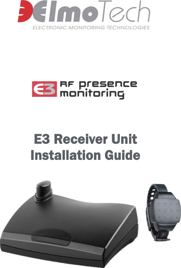
Attenti DCU-2010-2 Data Collection Unit User Manual E3 Landline Receiver and Transmitter

3M Electronic Monitoring, Inc. Data Collection Unit E3 Landline Receiver and Transmitter

User Manual

  E3 Receiver Unit  Installation Guide
    Information in this documentation is subject to change without notice and does not represent a commitment on part of Elmo-Tech Ltd. The software described in this document is subject to the license agreement that is included with the product, which specifies the permitted and prohibited uses of the product. Any unauthorized duplication or use of this documentation, in whole or in part, in print, or in any other storage or retrieval system is prohibited.  No part of this publication may be reproduced, transmitted, transcribed, stored in a retrieval system, or translated into any language in any form by any means for any purpose other than the purchaser’s personal use without the permission of Elmo-Tech Ltd. © 2002-08 Elmo-Tech Ltd. All rights reserved. Unless otherwise noted, all names of companies, products, street addresses, and persons contained herein are part of a completely fictitious scenario and are designed solely to document the use of an Elmo-Tech product.  Contact Us Corporate Headquarters Elmo-Tech Ltd. 2 Ha-Barzel St., P.O. Box 13236, 61132 Tel Aviv, Israel Tel: 972-3-7671800 Fax: 972-3-7671801 U.S.A Customers, call 1-800-313-1483 E-mail: contact@elmotech.com Visit us at: www.elmotech.com
 Table of Contents 1 Introduction.................................................................... 1 2 The Monitor Center or Probation Agency......................... 3 Required Equipment.......................................................... 3 3 The Offender’s Curfew Location...................................... 5 E3 Receiver Unit Location................................................... 5 Installing the E3 Receiver Unit............................................ 6 4 Installing the Transmitter............................................... 9 Activating the Transmitter (Tx) ........................................... 9 Attaching the Transmitter .................................................10 5 Activating the E3 Receiver Unit..................................... 13 Downloading Curfew Schedules and Operational Parameters ..13 Performing a Range Test...................................................14 6 Daily Operating Instructions......................................... 17 Incoming Calls (E3 Landline Receiver Unit) ..........................17 Accepting an Incoming Call...........................................17 Outgoing Calls (E3 Landline Receiver Unit) ..........................18 Performing an Outgoing Call .........................................18 Incoming Calls (E3 Cellular Receiver Unit) ...........................19 Accepting an Incoming Call...........................................19 Outgoing Calls (E3 Cellular Receiver Unit) ...........................19 Performing an Outgoing Call .........................................20     i
E3 Landline Receiver Unit and Transmitter Installation Guide   General Rules for the Offender...........................................21 7 Removing the Monitoring System ................................. 23 Performing an End of Service.............................................23 Disconnecting and Packing the E3 Receiver Unit ...................24 Removing the Transmitter.................................................24 Deactivating the Transmitter .............................................25 8 Monitoring System Maintenance ................................... 27 Cleaning the E3 Receiver Unit............................................27 Cleaning the Transmitter...................................................28 Replacing the Transmitter Straps .......................................29 9 System Specifications ................................................... 33 Transmitter Specifications.................................................33 E3 Receiver Unit Mechanical/Electrical Characteristics...............33 10 FCC Information............................................................ 34  ii
  List of Figures     iii List of Figures Figure 1  Ideal E3 Receiver Unit Location ...................................... 5 Figure 2  E3 Receiver Unit Installation Diagram.............................. 7 Figure 3  Removing the Transmitter ............................................25
     1 1  Introduction Welcome to the Electronic Monitoring System and correctional tool, created by Elmo-Tech Ltd. that has the ability to collect, analyze and intelligently act on information from multiple sources. An inconspicuous Transmitter (TX) is attached to the client's ankle or wrist by means of a tamper-detecting strap. The client's presence (or absence) is tracked constantly by radio transmissions between the Transmitter and the E3 Receiver Unit (DCU-2010 or DCU-2010C). When the client enters or leaves the defined home environment, the E3 Receiver Unit records the event. The E3 Receiver Unit then checks the client’s stored curfew schedule to determine if the event is in violation of his or her curfew order.  The E3 Receiver Unit reports certain violations to the Monitor Center as soon as they occur. All violation, non-violation events that are not defined as immediate are stored in the E3 Receiver Unit for the next upload. The E3 Receiver Unit initiates a pre-defined routine sanity call to the Monitor Center in order to report the status of the equipment and upload stored events. This event information completes the audit trail of the client’s behavior. The E3 Receiver Unit detects and reports tilting, loss of power, loss of telephone line, low battery, and other alarm conditions. The E3 Receiver Unit also detects Transmitter tampering, Transmitter removal and low battery.
 2  The Monitor Center or Probation Agency At the monitor center or probation agency, perform the following: 1. Enter the Offender’s personal information and E3 Receiver Unit configuration parameters into the Electronic Monitoring System software application. This can be done well in advance, even before the actual monitoring equipment is allocated and installed. 2. Enter the following equipment data into the Electronic Monitoring System software application: f E3 Receiver Unit serial number f Transmitter serial number 3. Check that the serial numbers entered match the numbers on each of the equipment items.  Note:  Serial numbers are visible on the back or side of each equipment item. Required Equipment Check that you have the following items of equipment before you leave the monitor center or probation agency: f E3 Receiver Unit and carrying case f Power adapter - 12VDC, 1A (DCU-2010) or 2A (DCU-2010C) f Telephone cables (DCU-2010 only) f Transmitter with Strap holder     3
E3 Receiver Unit and Transmitter Installation Guide   4   f Electronic key f Locking tool f Locking clips (male and female)  f Screwdriver (to open the clips if necessary). It is recommended to use a 0.2in (5mm) flat head screwdriver.  Note:  It is always recommended to bring an extra set of locking clips, in the event that the first set get accidentally damaged during the installation.
 3  The Offender’s Curfew Location In order for the Electronic Monitoring System to monitor the Offender in the home environment effectively you will need to find the best location for the E3 Receiver Unit.  E3 Receiver Unit Location The following figure shows how to find the best location for the E3 Receiver Unit.  Figure 1  Ideal E3 Receiver Unit Location     5
E3 Receiver Unit and Transmitter Installation Guide   The ideal location for the E3 Receiver Unit is in the center of the house, 3 ft (1m) off the ground and at least 1 ft (30cm) away from the wall. The E3 Receiver Unit should be located in an open area away from other electrical appliances (e.g. personal computers, laptops) or any metal objects. Installing the E3 Receiver Unit For the E3 Receiver Unit to receive and transmit signals with maximum efficiency it should be mounted on a hard flat surface with the antenna positioned upright. The E3 Receiver Unit should also be mounted within easy reach of a power outlet.  Note:  The distance between the wall and the E3 Receiver Unit should be at least 1 ft (30cm). To install the E3 Landline Receiver Unit (DCU-2010): 1. Disconnect the telephone cord from the wall telephone socket and connect it into the Phone socket (right) located on the back panel of the E3 Receiver Unit. 2. Connect one end of the supplied telephone cord into the Line socket (left) located on the back panel of the E3 Receiver Unit and plug the other end into the wall telephone socket. 3. Connect the adapter end of the supplied power adapter cord into a power outlet.  Note:  If any of the communication lines are incorrectly connected, a 3-second audible beeping sound will be heard from the E3 Receiver Unit. 6
  3   The Offender’s Curfew Location  Figure 2  E3 Receiver Unit Installation Diagram 4. Connect the other end of the supplied power adapter cord into the power socket located on the back panel of the E3 Receiver Unit. The E3 Receiver Unit makes an audible beeping sound and the left and right external LED’s, located on the back panel, are turned on. This indicates that the E3 Receiver Unit is in a satisfactory working state. The LED indicators are: f Left - indicates that the external power is connected f Right - indicates that the unit is connected to the telephone line The E3 Receiver Unit will automatically switch to standby mode.     7
E3 Receiver Unit and Transmitter Installation Guide   8    Note:  In standby mode the middle LED flashes and an audible beeping sound is heard from the E3 Receiver Unit every time the unit senses a Transmitter within its defined reception range.  To install the E3 Cellular Receiver Unit (DCU-2010C): 1. Connect the adapter end of the supplied power adapter cord into a power outlet. 2. Connect the other end of the supplied power adapter cord into the power socket located on the back panel of the E3 Cellular Receiver Unit. The E3 Cellular Receiver Unit makes an audible beeping sound and the left and right external LED’s, located on the back panel, are turned on. This indicates that the E3 Cellular Receiver Unit is in a satisfactory working state. The LED indicators are: f Left - indicates that the external power is connected. f Right - indicates that the unit has connected to the cellular network (network connection may take up to a minute). The E3 Cellular Receiver Unit will automatically switch to standby mode.  Note:  In standby mode the middle LED on the unit flashes and an audible beeping sound is heard from the E3 Cellular Receiver Unit every time the unit senses a Transmitter within its defined reception range.
 4  Installing the Transmitter Once the E3 Receiver Unit has been connected and is working correctly, you can calibrate and install the Transmitter (Tx). Check that you have the following equipment items before you install the Transmitter: f Transmitter (Tx) and Strap holder f Locking clips (male and female) f Strap holder f Electronic key f Locking tool f Screwdriver (to open the clips if necessary). It is recommended to use a 5mm flat head screwdriver Activating the Transmitter (Tx) Before the Transmitter can be attached to the Offender, you must first activate and calibrate the Transmitter. To activate and calibrate the Transmitter: 1. Hold the Transmitter in your hand with the metal pins (along the strap) pointing towards you. You will need to support the underside of the strap. 2. Hold the electronic key in your other hand, with the ‘OFF’ button pointing towards the open or free end of the strap. The ‘OFF’ button must be facing away from the Transmitter body. 3. Press the electronic key down over the metal pins with the two touch points on top of the electronic key matching the metal pins on the Transmitter strap.      9
E3 Receiver Unit and Transmitter Installation Guide   4. Hold the electronic key and the Transmitter strap in this position while you perform the next step. 5. Press the ‘ON’ on the electronic key for one second; the red LED light on the electronic key turns steadily on for two seconds. If the Transmitter successfully received the activate/calibrate commands the red light on the electronic key will flash for two seconds.  Note:  If the Transmitter failed to receive the activate/calibrate command, the red light on the electronic key will turn off after the initial two seconds on. If the electronic key’s battery is low, the red light will immediately flash for two seconds once the ‘ON’ button is pressed. 6. Place the Transmitter on its side, on a non-metal table and wait for about thirty seconds. To deactivate the Transmitter, simply follow the instructions from steps 1 to 6 above, but instead of pressing the ‘ON’ button on the electronic key to activate/calibrate the Transmitter, press the ‘OFF’ button. Attaching the Transmitter To attach the Transmitter to the offender:  1. Place a strap holder over the short strap (strap with pin side) of the Transmitter.  10
  4   Installing the Transmitter 2. Attach the female Clip to the underside of the Transmitter’s short strap (to lie against the Offenders skin). Check that the closed end of the clip fits with the edge of the strap.  3. Wrap the Transmitter around the Offender’s wrist/ankle at its narrowest point. 4. Lay the long strap over the female clip ensuring that all pins on the short strap are protruding through the long strap.  5. Slide the strap holder over the end of the long strap in order to hold it in place.    Note:  The Transmitter must fit tightly around the Offender’s wrist/ankle, but not squeezing. It is also permissible to wear a sock underneath the ankle Transmitter. Try to mount the Transmitter over the sock before it is fastened. 6. Cover the female clip with the male clip ensuring that the pins on the male clip fit correctly into the female clip (the grooves on the side of each clip must match).      11
E3 Receiver Unit and Transmitter Installation Guide   12   7. Ask the Offender to stand up and move around to ensure that the Transmitter is comfortable. 8. Fasten the two clips using the specially designed locking tool. An audible clicking sound should be heard, indicating that the clips are closed properly.  Note:  Once the Transmitter has been activated and attached to the offender’s wrist or ankle and the relevant offender is within the defined reception range of the E3 Receiver Unit, the E3 Receiver Unit locks onto and starts to monitor the Transmitter.
 5  Activating the E3 Receiver Unit In order to activate the E3 Receiver Unit, you will first need to download the Offender’s curfew schedule and the E3 Receiver Unit’s operational parameters. Downloading Curfew Schedules and Operational Parameters  Downloading the curfew schedule and general operational parameters requires that the central monitoring server (CMS) located at the monitoring center initiate a call to the E3 Receiver Unit. Once the appropriate landline connection is made, the download process can commence. To initiate the download: 1. Verify that the right LED located on the back panel of the E3 Receiver Unit is constantly on and not flashing.  Note:  If the right LED is flashing, it means that the line is currently busy and you will have to wait until the line is free. 2. Using a mobile phone, call the monitoring center and ask the monitoring personnel to perform a manual download. 3. Monitor the download communication process directly from the E3 Receiver unit (LED panel).     13
E3 Receiver Unit and Transmitter Installation Guide   The monitoring center personnel will call back to confirm a successful download, or to inform you that the download failed and must be initiated again. If the download was successful, the following data will be downloaded: f Transmitter serial number f The offender’s curfew schedule f Sanity call time intervals f E3 Receiver Unit event configuration f E3 Receiver Unit initial range setting f Grace time and violation sensitivity settings f E3 Receiver Unit operational parameters After the download process has been confirmed as successful, the E3 Receiver Unit will automatically switch to monitoring mode.  Note:  Monitoring mode will only start if the Offender’s defined program start time, as defined in the Electronic Monitoring System software application, has arrived. Performing a Range Test A range test is performed in order to define the appropriate reception range between the Transmitter and the E3 Receiver Unit. The range test is designed in order to create a limited free movement area. The Offender will use this limited free movement area while he/she is inside his/her home monitoring environment. To perform range test: 1. Estimate the size of the Offenders premises and decide on the initial range setting for the E3 Receiver Unit (e.g. medium). 14
  5   Activating the E3 Receiver Unit 2. Verify that the telephone line LED (right) located on the back panel of the E3 Receiver Unit is constantly on and not flashing. 3. Using a mobile phone, call the monitoring center and ask the monitoring personnel, first, to adjust the range settings in the monitoring center software application to the range setting that you noted during your estimation, and then to perform a range test (start range). Once the range test has been activated, the following occurs: f The Offender’s telephone rings 2-3 times and then stops. f The telephone line LED (right) located on the back panel on the E3 Receiver Unit flashes and then returns to its steady state.  f The Transmitter reception LED (middle) blinks 3 times in quick succession accompanied by 3 audible beeping sounds. This indicates that the E3 Receiver Unit is in range test mode and the range test has started.  Note:  The E3 Receiver Unit will be in range test mode for approximately 15 minutes, unless the monitoring center personnel terminate the range test manually. 4. Escort the Offender to the following locations in his/her home monitoring environment: f Locations that are the most distant from the E3 Receiver Unit f Locations behind large metal objects f Location where the Offender spends long periods of time (bedroom. toilet, living room, etc.) f Remote location where the Offender is allowed to be while in his/her home monitoring environment (garage, cellar, yard, garden, etc.)     15
E3 Receiver Unit and Transmitter Installation Guide   16   f Any location that your experience and common sense suggests to be a viable location for range testing 5. An assistant should stand next to the E3 Receiver Unit and observe the Transmitter reception LCD (middle). Every time the E3 Receiver Unit receives a transmission signal from the Offender’s Transmitter (approx. every 20 seconds) the Transmitter reception LCD (middle) flashes 3 times in quick succession. 6. Wait at least two minutes in each range testing location.  Note:  During these two minutes, four transmissions should be received from the Transmitter. If four or more transmissions are received from the Transmitter before the two minutes have elapsed, you can move onto the next location. If less than four transmissions are received, call the monitor center personnel and request a change in the range setting, preferably to a longer range. If the range setting is already set at its maximum range and you still don’t receive four transmissions in a two-minute time period, you will need to relocate the E3 Receiver Unit and restart the range test. 7. After satisfactory testing of all relevant locations, call the monitoring center and ask the monitoring personnel to manually stop the range test (end range). 8. Upon ending the range test the E3 Receiver Unit makes an audible beeping sound to indicate the range test completion.
 6  Daily Operating Instructions If using the E3 Landline Receiver Unit, the Electronic Monitoring System is generally transparent to the user of the telephone. The E3 Receiver Unit while connected to the telephone is capable of accepting incoming calls and performing outgoing calls. The E3 Cellular Receiver Unit is capable of accepting calls from the Monitoring Center and allows the Offender to perform predefined outgoing calls to the Monitoring Center or emergency services. Incoming Calls (E3 Landline Receiver Unit) The E3 Receiver unit may receive two types of incoming calls; regular calls from friends or family and the occasional call from the monitoring center computer. All incoming calls trigger a pre-defined number of rings (depending on the defined default setting – 6 rings) before the E3 Receiver Unit picks up the call. Accepting an Incoming Call When accepting an incoming call the following should be noted: f The phone will ring up to six times, during which the call may be answered by the Offender. After six rings have expired, the E3 Receiver Unit will automatically answer, and then disconnect the call f If the Offender, after answering the call, hears a light audible sound on the line during the first few seconds of the conversation, he / she should not be alarmed. The E3 Receiver Unit automatically interacts with each incoming call for the first few seconds     17
E3 Receiver Unit and Transmitter Installation Guide   f During the conversation, the Offender may hear a short audible tune coming from the E3 Receiver Unit. This tune indicates that the E3 Receiver Unit needs to call the monitoring center computer. The Offender should complete his / her conversation as soon as possible to enable the E3 Receiver Unit to make its call. Failure to give up the line could result in a violation. Outgoing Calls (E3 Landline Receiver Unit) The E3 Receiver unit can perform two types of outgoing calls; regular calls to friends or family and the occasional call, initiated by the E3 Receiver Unit, to the monitoring center computer, either to report a violation, or to report its current status. Performing an Outgoing Call When performing an outgoing call the following should be noted: f If the Offender tries to perform an outgoing call and hears a sharp modem sound, the call attempt must be terminated. This indicates that the E3 Receiver Unit needs to call the monitoring center computer. Failure to give up the line could result in a violation f During the conversation, the Offender may hear a short audible tune coming from the E3 Receiver Unit. This tune indicates that the E3 Receiver Unit needs to call the monitoring center computer. The Offender should complete his / her conversation as soon as possible to enable the E3 Receiver Unit to make its call. Failure to give up the line could result in a violation. 18
  6   Daily Operating Instructions Incoming Calls (E3 Cellular Receiver Unit) The E3 Cellular Receiver unit may receive two types of incoming calls; test request calls from the voice verification engine (for voice verification programs) and the occasional call from the monitoring center computer.  Accepting an Incoming Call To accept an incoming call: When the E3 Cellular Receiver unit rings, lift the phone and press the Answer button.  Note:  The phone will ring up to six times, during which the call may be answered by the Offender. After six rings have expired, the E3 Cellular Receiver Unit will automatically answer, and then disconnect the call. To terminate a call: Press the End button. Outgoing Calls (E3 Cellular Receiver Unit) The Offender may perform two types of outgoing calls; test request calls to the voice verification engine (for voice verification programs) and emergency calls to the monitor center or emergency services. The phone numbers of these destinations are downloaded to the E3 Cellular Receiver.     19
E3 Receiver Unit and Transmitter Installation Guide   Performing an Outgoing Call To place an outgoing call: Lift the phone on the E3 Cellular Receiver and press one of the following buttons: f Call – for the monitoring center as well as the voice verification engine (for voice verification program). f Emergency – for the emergency services (e.g. 911 in the USA), or the monitoring center (for voice verification program).  Note:  Once you press the desired button a short audible beeping sound is heard. A lower tone beeping sound can be heard when the E3 Cellular Receiver unit fails to perform the outgoing call. To end a call: Press the End Button and place the phone in its cradle.  20
  6   Daily Operating Instructions  General Rules for the Offender The following points describe the rules for the Offender regarding the Electronic Monitoring System.  Warning!  Never… f Touch or move the E3 Receiver Unit once it has been installed f Place any objects on top of the E3 Receiver Unit f Disconnect the power cord from either the E3 Receiver Unit f Attempt to open the E3 Receiver Unit f Move out of the designated curfew area during an in-house curfew time frame f Attempt to open the Transmitter strap f Cut or break the Transmitter strap or clip The following appliances are prohibited (E3 Landline Receiver Units only): f Answering Machine f Fax Machine f Fax / Modem f ADSL Internet Service f Special services supplied by the telephone company e.g. call forwarding or call waiting     21
 7  Removing the Monitoring System In some cases it is required to remove the monitoring system before the defined confinement period is completed. Before disconnecting and removing the E3 Receiver Unit, an end of service procedure should be performed.  Note:  Performing an end of service before disconnecting and removing the E3 Receiver Unit is essential to preserving the unit’s internal backup battery. Performing an End of Service To perform an end of service: 1. Using a mobile phone, call the monitoring center and ask the monitoring personnel to perform a manual end of service. 2. The monitoring center personnel will call back to confirm a successful end of service. You can now disconnect and pack the E3 Receiver Unit into its original package.  Note:  It is recommended that only experienced personnel remove the E3 Receiver Unit.     23
E3 Receiver Unit and Transmitter Installation Guide   Disconnecting and Packing the E3 Receiver Unit To disconnect and pack the E3 Receiver Unit: 1. Remove the power adapter from the wall. 2. For E3 Landline receiver units, remove all telephone cables from the back of the unit and reconnect the telephone line to the wall socket. 3. Pack the E3 Receiver Unit into its original package and place into the carrying case. 4. Pack the power-cord adapter and telephone cables into their original packaging and place into the carrying case. You can now remove and pack the Transmitter.  Note:  It is recommended that only experienced personnel remove the Transmitter. Removing the Transmitter To remove the Transmitter: 1. Check the following signs to see if the clips have been tampered with: f Cracks on the clips f Broken pins f Sign of adhesive or glue 2. Being careful not to damage or cut the strap, use a screwdriver to break the disposable clips. 24
  7   Removing the Monitoring System  Screwdriver Grooves Figure 3  Removing the Transmitter 3. Collect all the fragments of the broken clip. Do not leave any disposable items. Deactivating the Transmitter Deactivating the Transmitter is essential to preserving the unit’s internal battery. To deactivate (turn off) the Transmitter: 1. Hold the Transmitter in your hand with the metal pins (along the strap) pointing towards you. You will need to support the underside of the strap. 2. Hold the electronic key in your other hand, with the ‘OFF’ button pointing towards the open or free end of the strap. The ‘OFF’ button must be facing away from the Transmitter body. 3. Press the electronic key down over the metal pins with the two touch points on top of the electronic key matching the metal pins on the Transmitter strap.  4. Hold the electronic key and the Transmitter strap in this position while you perform the next step. 5. Press the ‘OFF’ on the electronic key for one second; the red LED light on the electronic key turns steadily on for two seconds. If the Transmitter successfully received the     25
E3 Receiver Unit and Transmitter Installation Guide   26   deactivate command the red light on the electronic key will flash for two seconds.  Note:  If the Transmitter failed to receive the deactivate command, the red light on the electronic key will turn off after the initial two seconds on. If the electronic key’s battery is low, the red light will immediately flash for two seconds once the ‘ON’ button is pressed. 6. Pack the Transmitter into its original packaging and place into the carrying case.
 8  Monitoring System Maintenance In order to keep the Electronic Monitoring System functional and in good working order a number of maintenance procedures will need to be adhered to.  Cleaning the E3 Receiver Unit To clean the E3 Receiver unit:  1. Remove the E3 Receiver unit from its carrying case. 2. Spray the surface of the E3 Receiver unit with an alcohol based cleaner (optional).  Note:  Elmo-Tech recommends Citrus Base cleaner by 3M™ (http://solutions.3m.com/). 3. Using a damp cloth, wipe the outside of the E3 Receiver unit.  Caution!  Do not submerge the E3 Receiver unit, or put it under running water. 4. Using a dry cloth, or paper towel, dry the outside of the E3 Receiver unit. 5. Once the E3 Receiver unit is dry, return it to its carrying case.     27
E3 Receiver Unit and Transmitter Installation Guide   Cleaning the Transmitter The Transmitter is made of a single mold, especially designed to protect the integrity of the electronic circuits during daily use and while it is being cleaned.  The following cleaning methods are approved by Elmo-Tech: f Manual Cleaning – using a soft brush and approved cleaning product. f Using a Dishwasher – together with an approved cleaning product. To clean the Transmitter manually:  1. Remove the Transmitter from its carrying case. 2. If there are clips on the Transmitter, remove the ‘female’ and ‘male’ parts before cleaning. 3. Remove the strap holder from the Transmitter. 4. Hold the Transmitter by the end of the long strap and either: f Spray the Transmitter with 3MTM Citrus Base cleaner, or an alcohol based equivalent. Or f Using a damp cloth or towel, clean the Transmitter with soapy water. 5. Using a dry cloth or towel, dry the outside of the Transmitter and place it on a towel with its inner side facing up. 6. Using a soft brush, gently brush the inner side of the Transmitter along the tracks. 7. After cleaning, wash the Transmitter in clean water. 8. Using a dry cloth or towel, dry the Transmitter thoroughly. 9. Place the strap holder back onto the short strap of the Transmitter. 28
  8   Monitoring System Maintenance 10. Place the Transmitter back into its carrying case. To clean the Transmitter using a dishwasher:  1. Remove the Transmitter from its carrying case. 2. If there are clips on the Transmitter, remove the ‘female’ and ‘male’ parts before cleaning. 3. Remove the strap holder from the Transmitter. 4. Place the Transmitter into the dishwasher machine. 5. Use a pH neutral or slightly acidic cleaning agent.  Note:  Elmo-Tech recommends Hepi dishwashing Products by Thurn-produckte (http://www.thurn-produkte.de/). 6. Choose the shortest cycle, at a maximum temperature of 52ºC. 7. Once the Transmitter is dry, place the strap holder back onto the short strap of the Transmitter. 8. Place the Transmitter back into its carrying case. Replacing the Transmitter Straps After some time and depending on the wear and tear of the Transmitter, the straps on the Transmitter will need to be replaced. Any of the following points could justify replacing a Transmitter strap: f Visible damage to one or both straps f Strap tamper alarm generated, with no visible damage to the Transmitter f Transmitter will not calibrate     29
E3 Receiver Unit and Transmitter Installation Guide    Note:  If only one side of the strap is damaged, you may want to leave the undamaged side in place and replace only the damaged side of the strap. Check that you have the following equipment items before you replace the Transmitter straps: f 1 Transmitter body f 1 pair of replacement straps (long/medium non-pins side and long/medium pins side) f Screwdriver f Extra screws f Extra strap clips (male and female) f Electronic key  To replacing the Transmitter straps: 1. Using the screwdriver, open the screw(s) that holds the strap clasp to the Transmitter and remove the strap clasp. 2. Gently shake the strap loose from the Transmitter body, being extra careful not to damage the metal pins on the Transmitter body. 3. Position the new strap over the Transmitter body. Notice that the two small holes on the strap have to lie exactly over the two metal pins. 4. Gently place the strap down over the metal pins and press down along the seam of the strap, snugly fitting the entire strap to the Transmitter body. 5. Put the strap clasp back in place with the wider side pointing in-wards. 6. Close the screw (s) with the screwdriver. It has to be closed firmly, but not too tight since this can damage the strap. 30
  8   Monitoring System Maintenance  7. Test the new strap by performing a calibration. Refer to the chapter about Installing the Transmitter.  Note:  If, after the calibration, the Transmitter does not reset, repeat steps 1-6 making sure that the strap is positioned correctly over the pins. Then perform another calibration test. If changing only one side of the strap does not work, you should try and change the other strap side.     31
 9  System Specifications This chapter lists the specifications details for each equipment item associated with the Electronic Monitoring System.  Transmitter Specifications f Transmitter size:  5.5 x 4.2 x 1.5 cm  (2.2 x 1.65 x 0.67 in) f Transmitter weight:  50 g (1.75  oz) f Fully adjustable / reusable straps  f Disposable locking clip f Shock resistant  f Multi tamper protection f Battery operational life:  18 / 36 months  f Battery shelf life: 2-3 years f Waterproof to 4.5 m (15 ft)   E3 Receiver Unit Mechanical/Electrical Characteristics f E3 Receiver Unit size:  25.5 x 19.5 x 7 cm  (10 x 7.4 x 2.6 in) f Antenna cover height:  3 cm (1.2 in) f Weight (without power adapter):  1 kg (2.20 lb) f Internal backup battery life: over 48 hours f Case tamper and Tilt detection  f Water Resistant f Power disconnect detection  f Operating Temperature:  5 o C to 55o C f Humidity: 0 to 93%  f Shock: 1.5 m (4.9 ft) fall without separation f Power Input: 12VDC, 1A (DCU-2010) or 2A (DCU-2010C)  f      33
E3 Receiver Unit and Transmitter Installation Guide   10  FCC Information DCU-2010 FCC ID: LSQ-DCU-2010-2 DCU-2010C FCC ID: LSQ-DCU-2010C-2 FEDERAL COMMUNICATIONS COMMISSION (FCC) Part 15 STATEMENT This equipment has been tested to FCC requirements and has been found acceptable for use. The FCC requires the following statement for your information. This equipment generates and uses radio frequency energy and if not installed and used properly, that is, in strict accordance with the manufacturer’s instructions, may cause interference to radio and television reception. It has been type tested and found to comply with the limits for a Class B computing device in accordance with the specifications in Part 15 of FCC Rules, which are designed to provide reasonable protection against such interference in a residential installation. However, there is no guarantee that interference will not occur in a particular installation. If this equipment does cause interference to radio or television reception, which can be determined by turning the equipment off and on, the user is encouraged to try to correct the interference by one or more of the following measures: • If using an indoor antenna, have a quality outdoor antenna installed. • Reorient the receiving antenna until interference is reduced or eliminated. • Move the receiver away from the control/communicator. • Move the antenna leads away from any wire runs to the control/ communicator. • Plug the control/communicator into a different outlet so that it and the receiver are on different branch circuits. If necessary, the user should consult the dealer or an experienced radio/television technician for additional suggestions. The user or installer may find the following booklet prepared by the Federal Communications Commission helpful: “Interference Handbook”. This booklet is available from the U.S. Government Printing Office, Washington, DC 20402. The user shall not make any changes or modifications to the equipment unless authorized by the Installation Instructions or User’s Manual. Unauthorized changes or modifications could void the user’s authority to operate the equipment. FEDERAL COMMUNICATIONS COMMISSION (FCC) Part 68 NOTICE This equipment complies with Part 68 of the FCC rules. On the bottom cover of this equipment is a label that contains, among other information, the FCC registration number and the ringer equivalence number (REN is 1.0 B) for this equipment. If requested, this information must be provided to the telephone company. This equipment uses the following jacks:   An RJ31X is used to connect this equipment to the telephone network. 34
  10   FCC Information     35 The REN is used to determine the quantity of devices which may be connected to the telephone line. Excessive RENs on the telephone line may result in the devices not ringing in response to an incoming call. In most, but not all areas, the sum of the RENs should not exceed five (5.0). To be certain of the number of devices that may be connected to the line, as determined by the total RENs, contact the telephone company to determine the maximum REN for the calling area. If this equipment causes harm to the telephone network, the telephone company will notify you in advance that temporary discontinuance of service may be required. If advance notice is not practical, the telephone company will notify the customer as soon as possible. Also, you will be advised of your right to file a complaint with the FCC if you believe necessary. The telephone company may make changes in its facilities, equipment, operations, or procedures that could affect the operation of the equipment. If this happens, the telephone company will provide advance notice in order for you to make the necessary modifications in order to maintain uninterrupted service. If trouble is experienced with this equipment, please contact the manufacturer for repair and warranty information. If the trouble is causing harm to the telephone network, the telephone company may request you remove the equipment from the network until the problem is resolved. There are no user serviceable components in this product, and all necessary repairs must be made by the manufacturer. Other repair methods may invalidate the FCC registration on this product. This equipment cannot be used on telephone company-provided coin service. Connection to Party Line Service is subject to state tariffs.  TRANSMITTER FEDERAL COMMUNICATIONS COMMISSION (FCC)  Part 15 STATEMENT The equipment complies with Part 15 of the FCC Rules.  Operation is subject to the following two conditions: (1) This device may not cause harmful interference, and (2) This device must accept any interference received, including interference that may cause undesired operation. This equipment has been tested and found to comply with the limits for a Class B digital device, pursuant to part 15 of the FCC Rules. These limits are designed to provide reasonable protection against harmful interference in a residential installation. This equipment generates, uses and can radiate radio frequency energy and, if not installed and used in accordance with the instructions, may cause harmful interference to radio communications. However, there is no guarantee that interference will not occur in a particular installation. If this equipment does cause harmful interference to radio or television reception, which can be determined by turning the equipment off and on, the user is encouraged to try to correct the interference by one or more of the following measures: 1. Reorient or relocate the receiving antenna, 2. Increase the separation between the equipment and the receiver, 3. Connect the equipment into an outlet on a circuit different from that to which the receiver is connected, 4. Consult the dealer or an experienced radio/TV technician for help.

Navigation menu