Attenti DEU-500 Data extending unit DEU-500 User Manual User manual
3M Electronic Monitoring, Inc. Data extending unit DEU-500 User manual
Attenti >
11 pages
USER MANUAL

DEU
(Data Extending Unit)
User Manual
December 99
Table of Contents
Introduction................................................................................ 4
Physical Appearance................................................................. 5
Recommendations for optimum performance......................... 6
Extra coverage........................................................................... 7
Mounting two DEU s................................................................ 8
Mounting Surfaces .................................................................... 9
Mounting Procedure.................................................................. 9
FCC Notice...........................................................................................11
1. Introduction
The DEU (Data Extending Unit) is a versatile combination of both a transmitter and receiver that is
designed to extend the range of the GMU (Group Monitoring Unit). The DEU’s unique design assists
in eliminating blind spots (areas where the GMU cannot receive a transmission) between the Tx
(transmitter) and the GMU.
The DEU’s effectiveness is its ability to receive weak transmissions that would not otherwise reach
the GMU because of poor site locations e.g. toilets, pillars, industrial noise etc, and boost these signals
onwards to the GMU. This feat therefore extends the transmission range between the GMU and the Tx
and maintains successful communication flow from Tx to GMU. The DEU acts as the bridge between
the Tx and the GMU.
The DEU receives transmissions from any Tx or another DEU (in the case where more than one DEU
is used) and transmits the received signal onwards, which in turn can be received by other DEU’s or
the GMU itself. This maintains that a transmission will successfully reach its destination, the GMU.
The DEU’s internal intelligence prevents two DEU’s from receiving and transmitting between one
another so entering into a loop. This maintains that the true transmission will be received by the GMU.
2. Physical Appearance
•• A 110V AC / 7.5V DC external power source powers the unit.
•• An internal battery offers 4 hours of operation life in the event that external power is removed.
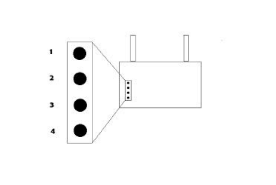
•• The faceplate of the DEU comprises of 4 Leds (light emitting diodes), 2 antennae’s for
optimum reception and an on/off key switch. The leds are explained as follows appearing on the
faceplate from top to bottom:
(1) Reception (blinks when receives transmissions)
(2) Transmission (blinks when transmitting)
(3) Internal backup battery OK (steady light)
(4) External Power OK (steady light)
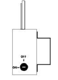
• On-Off Key:
The DEU is switched on and off by turning the On-Off key to the appropriate position,
upward for off and sideways for on.
3. Recommendations for optimum performance
The most important consideration of the DEU is its placement.
It should be mounted in an area, in which the transmission signal is still prominent in
order to receive and boost the signal effectively onwards towards the GMU.
One) Try to mount the unit in line of sight of the GMU, in the instance where there are many
disturbances to the signal strength e.g. walls, obstacles etc.
Two) The unit should be mounted 220-250cm above the floor.
Three) Do not mount the DEU in a corner.
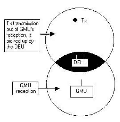
4. Extra coverage
The DEU assists the GMU in its ability to receive transmissions that the GMU may not have
received due to site hazards (pillars, toilets etc), thereby providing an extra receptive coverage
range for the GMU.
DEU receives a weak transmission and boosts it forward towards the GMU
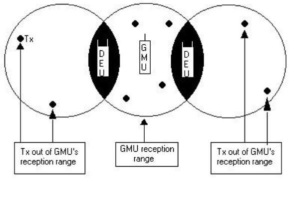
5. Mounting two DEU’s
(One) In the event where one DEU does not provide sufficient coverage, a second DEU may be
mounted.
(Two) Attempt to mount the DEU’s in line of sight with each other, with the GMU appearing in
between them.
(Three) Try to ensure that each DEU’s transmission range is not received by the other DEU.
Two DEU’s receive transmissions from Tx’s out of the GMU’s reception range and transmits
them inwards towards the GMU.
6. Mounting Surfaces
Preferably a wall or flat surface with a power outlet within reach (non-metallic
surface).
7. Mounting Procedure
The mounting procedure of the DEU is very simple. It dismisses the need for screws, mounting tools
etc as well as the responsibility of having to fix the DEU in one fixed spot. The mounting procedure
offers portability if need be.
There are 3 variables to mounting the DEU namely mounting brackets, a black ‘velcro’ grip and a
transparent ‘velcro’ grip.
Mounting brackets
The backside of the DEU has 2 fixed mounting brackets. Stuck permanently on each bracket is a black
‘velcro’ grip.
Black ‘velcro’ grip
The black ‘velcro’ grip offers visible and durable bristles for mating with the transparent ‘velcro’ grip
Transparent ‘velcro’ grip
The transparent ‘velcro’ has a dual function. One side has strong bristles used to fit snugly into the
bristles of the black ‘velcro’.
The other side acts like a sticker (to stick the unit physically to the wall).
When a suitable mounting place is found, peel off the strips allowing the sticky side to grip and stick to
the wall. The DEU is now firmly mounted.
Moving the DEU to another location
By relieving the grip between the bristles of both ‘velcro’s, the DEU can now be freed to be mounted
somewhere else.
Turn the DEU onto its faceplate with the brackets facing upwards. Using a spare transparent ‘velcro’
firmly press the bristles of the two ‘velcro’s’ together. By peeling off the sticky end of the transparent
‘velcro’, the DEU may be mounted else-where.
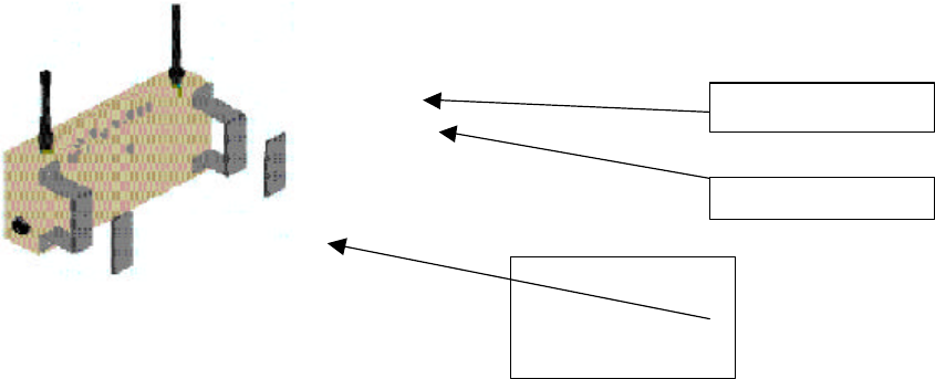
Schematic view of the mounting procedure
Mounting bracket
Black ‘velcro’
Transparent ‘velcro’
snugly fits into the
black ‘velcro’ and
sticks to the wall
FCC Notice
This equipment has been tested and found to comply with the limits of a Class B digital device,
pursuant to Part 15 of the FCC Rules. These limits are designed to provide reasonable protection
against harmful interference in a residential installation. This device generates, uses, and can radiate
radio frequency energy and, if installed and used in accordance with the instruction, may cause harmful
interference to radio communications. However, there is no guarantee that interference will not occur
in a particular installation. If this device does cause harmful interference to radio or television
reception, which can be determined by turning the equipment off and on, the user is encouraged to
correct the interference by one or more of the following measures:
Reorient or relocate the receiving antenna.
Increase the separation between the equipment and receiver.
Connect the equipment into an outlet on a circuit different from that to which the receiver
is connected.
Consult the dealer or an experienced radio/TV technician for help.
CAUTION: Any changes or modifications to this equipment not expressly approved by Elmo Tech
Ltd could void the user’s authority to operate the equipment.