Attenti IDEU-810-4 Data Extending Unit User Manual TABLE OF CONTENTS
3M Electronic Monitoring, Inc. Data Extending Unit TABLE OF CONTENTS
Attenti >
Contents
- 1. Users Manual 1
- 2. Users Manual 2
- 3. Users Manual 3
Users Manual 2

iDEU-810 Installation and Operational Guide
1 Introduction
The new improved Wireless Monitoring Unit (iDEU-810-4) is a versatile
combination of both transmitter and receiver that is designed to extend the
transmission / reception range of HomeFree at Care Centers systems.
The Wireless Monitoring Unit (iDEU-810-4) is one of many specifically
positioned mini control units that are placed at various locations throughout
the facility and are capable of receiving transmission signals from multiple
sources and then transferring these signals to the next Wireless Monitoring
Unit (iDEU-810-4) in the network or directly to the Wireless Monitoring
Base Unit.
The Wireless Monitoring Unit (iDEU-810-4) transmits on an American FCC
tested and approved frequency; whereas the European version (iDEU-810-4)
transmits on a European tested and approved frequency. From a user
interface and functional point of view, the two models are identical,
therefore this installation and operational guide serves both versions.
1-1
iDEU-810 Installation and Operational Guide
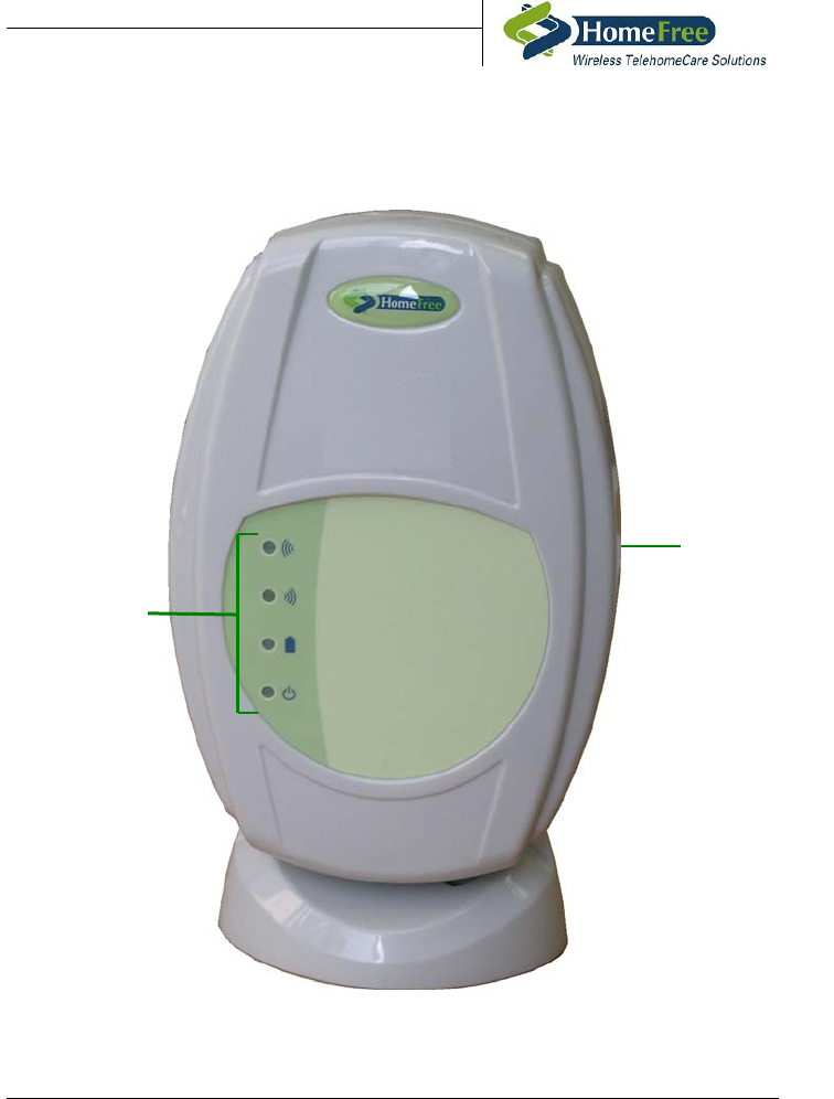
1.1 Parts of the Wireless Monitoring Unit
(iDEU-810-4)
Mounting
Bracket
LED Panel
Figure 1-1 Wireless Monitoring Unit (iDEU-810-4)
1-2

iDEU-810 Installation and Operational Guide
1.1.1 LED Panel
The faceplate of the Wireless Monitoring Unit (iDEU-810-4) comprises of 4
LEDs (Light emitting diodes).
The purpose of each LED is explained in the following table:
LED Description and Purpose
Reception Blinks when receiving transmission signals
Transmission Blinks when transmitting signals
Charge Steady light indicates internal battery is fully
charged. Charge LED blinks when internal
battery is not fully charged
Power Steady light indicates external power OK.
Power LED blinks when external power is
disconnected
1-3

iDEU-810 Installation and Operational Guide
2 Mounting the Wireless Monitoring
Unit (iDEU-810-4)
For a Wireless Monitoring Unit to receive and transmit signals with
maximum efficiency, it should be mounted on a wall or flat surface and
positioned upright. The Wireless Monitoring Unit should also be mounted
within reach of a power outlet (an electrician my need to install a power
outlet near the chosen Wireless Monitoring Unit location).
Note that the distance between the wall and the Wireless Monitoring
Unit should be at least 10 cm.
There are two ways to mount the Wireless Monitoring Unit. The first is to
mount the Wireless Monitoring Unit on the wall using the fixed mounting
brackets together with the dowel and screw fitting, and the second is to use
the fixed mounting brackets and a Velcro fitting. Both of these fitting
options are supplied with the Wireless Monitoring Unit.
2.1 Permanent Anchor/Dowel Wall Fitting
The anchor/dowel wall fitting is generally used for installing the Wireless
Monitoring Unit in a permanent location.
In order to mount the Wireless Monitoring Unit using the anchor/dowel wall
fittings, perform the following:
1. Place the Wireless Monitoring Unit on its faceplate with the fixed
mounting brackets facing upwards.
2. Make a drilling template by tracing around the mounting brackets on the
back of the Wireless Monitoring Unit onto a piece of A4 paper, not
forgetting to mark the holes for the anchor/dowels.
2-4

iDEU-810 Installation and Operational Guide
3. Using the template, drill two holes in the wall and place the supplied
wall anchors/dowels into these holes.
4. Insert the supplied bolts/screws into the wall dowels, ensuring not to
tighten the bolts/screws completely.
5. Holding the Wireless Monitoring Unit with the mounting brackets
facing away from you, maneuver the holes on the mounting brackets
over the bolts/screws already attached to the wall.
6. Pull the mounting brackets down over the bolts/screws slightly to ensure
that the bolts/screws lock into the holes on wall bracket.
7. Using an extension ratchet, tighten the bolts/screws until the Wireless
Monitoring Unit sits firm against the wall and does not move in any
way.
2.2 Temporary Velcro Wall Fitting
The Velcro wall fitting may be used for installing the Wireless Monitoring
Unit in a temporary location (e.g. during pre-installation and range setting
procedures).
In order to mount the Wireless Monitoring Unit using the supplied Velcro
wall fittings, perform the following:
1. Place the Wireless Monitoring Unit on its faceplate with the fixed wall
brackets facing upwards.
2. Peel off the paper strip from the backside (smooth side) of the black
Velcro attachment and press the sticky side down onto the wall bracket.
Do this for both wall brackets.
3. Place the bristle side of the transparent Velcro attachment on top of the
black Velcro attachment and press down firmly, connecting the two
Velcro attachments together.
4. Peel off the paper strip from the backside (smooth side) of the
transparent Velcro attachment.
2-5

iDEU-810 Installation and Operational Guide
5. Holding the Wireless Monitoring Unit with the mounting brackets
facing away from you, maneuver the Wireless Monitoring Unit to a
suitable mounting location.
6. Using sufficient pressure, adhere the mounting bracket on the Wireless
Monitoring Unit, to the wall.
2-6

iDEU-810 Installation and Operational Guide
3 Activating the Wireless
Monitoring Unit
In order to activate the Wireless Monitoring Unit, perform the following:
1. Connect the adapter end of the power supply to a power outlet.
2. Connect the small end of the supplied power supply into the 7.5 VDC
power socket located on the side panel of the Wireless Monitoring Unit.
The Wireless Monitoring Unit makes three audible beeping sounds. The
Charge LED on the front panel flashes when the Wireless Monitoring Unit is
first activated. The Charge LED and Power LED light up only after the
backup battery is fully charged. The Wireless Monitoring Unit is now in
monitoring mode.
3-7

iDEU-810 Installation and Operational Guide
4 FCC Notices
This note is applicable to the American Wireless Monitoring Unit (iDEU-810-4)
NOTE - The Wireless Monitoring Unit (iDEU-810-4) complies with Part 15
of the FCC Rules. Operation is subject to the following two conditions:
(1) This device may not cause harmful interference, and
(2) This device must accept any interference received, including interference
that may cause undesired operation.
This device has been tested and found to comply with the limits of the Class
B digital device, pursuant to Part 15 of the FCC rules. These limits are
designed to provide reasonable protection against harmful interference in a
residential installation. This device generates, uses and can radiate radio
frequency energy and, if installed and used in accordance with the
instruction, may cause harmful interference to radio communications.
However, there is no guarantee that interference will not occur in a
particular installation. If this device does cause harmful interference to radio
or television reception, which can be determined by turning the equipment
off and on, the user is encouraged to correct the interference by one or more
of the following measures
• Reorient or relocate the receiving antenna
• Increase the separation between the equipment and the receiver.
• Consult the dealer or an experienced radio/TV technician for help.
CAUTION – Any changes or modifications not expressly approved by the
grantee of this device could void the user’s authority to operate the
equipment.
4-8

iDEU-810 Installation and Operational Guide
For Customer Support contact:
Home Free Systems Inc.
Wireless TelehomeCare Solutions
6629 West Mill Road
Milwaukee, WI 53218
USA
Toll Free 1-800-606-0661
Fax +1-414-358-8100
Web: http://www.homefreesys.com
4-9