Attenti MU-800 Mobile Unit User Manual MONITORING WORK STATION
3M Electronic Monitoring, Inc. Mobile Unit MONITORING WORK STATION
Attenti >
Users Manual
Mobile Unit –User Manual
ELECTRONIC MONITORING SYSTEM
MOBILE UNIT OPERATIONAL
GUIDE
September 2003
Mobile Unit Operational & Maintenance Guide
1-1

Mobile Unit –User Manual
Mobile Unit Operational & Maintenance Guide
1-2
Information in this documentation is subject to change without notice and
does not represent a commitment on part of ElmoTech Ltd. The software
described in this document is subject to the license agreement that is
included with the product, which specifies the permitted and prohibited uses
of the product. Any unauthorized duplication or use of this documentation,
in whole or in part, in print, or in any other storage or retrieval system is
prohibited. No part of this publication may be reproduced, transmitted,
transcribed, stored in a retrieval system, or translated into any language in
any form by any means for any purpose other than the purchaser’s personal
use without the permission of ElmoTech Ltd.
© 2002 ElmoTech Ltd. All rights reserved.
Unless otherwise noted, all names of companies, products, street addresses,
and persons contained herein are part of a completely fictitious scenario and
are designed solely to document the use of an ElmoTech product.
Contact Us
Corporate Headquarters
ElmoTech Ltd.
2 Ha-Barzel St.,
P.O. Box 13236,
61132 Tel Aviv, Israel
Tel: 972-3-7671800
Fax: 972-3-7671801
U.S.A Customers, call 1-800-313-1483
E-mail: contact@elmotech.com
Visit us at: www.elmotech.com
Mobile Unit –User Manual
Chapter 1: Introduction
The Mobile Monitoring System is based on Elmo-Tech’s field proven RF
monitoring technology. The Mobile Unit is one of the many unique elements
of this system.
Mobile Unit Operational & Maintenance Guide
1-3
he
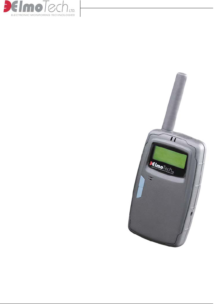
The Mobile Unit is a lightweight hand
held unit that can be used by mobile
officers in the field to monitor offender
transmitters.
The Mobile Unit has the following
features and advantages:
Ability to verify monitored offender
compliance while patrolling in a vehicle,
or on foot
Minimizing direct unnecessary contact
with offenders
Light, palm sized and water-resistant new
design
18 hour rechargeable battery
Extended memory capacity
Windows™ PC interface, for batch report
processing
The groundbreaking GPS model will
report the offender’s location and
immediately upload this information to t
monitoring center.
Mobile Unit –User Manual
Chapter 2: Mobile Unit Activation
and Setup
The Mobile Unit is a lightweight hand held unit that can be used by mobile
officers in the field to monitor offender transmitters.
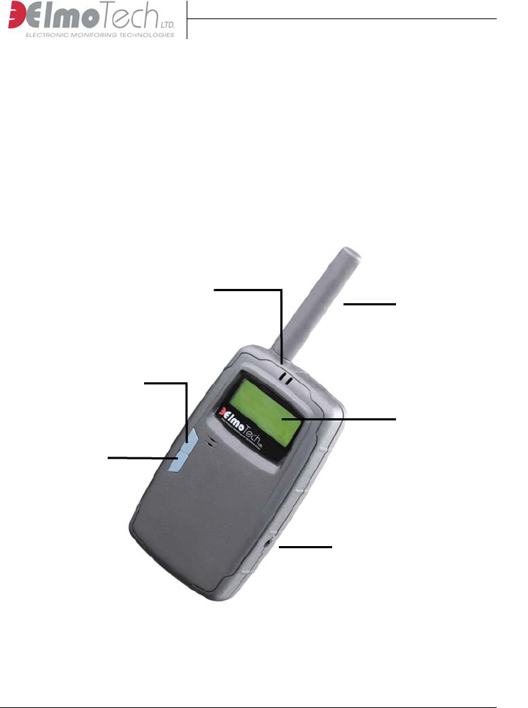
2.1 Parts of the Mobile Unit
LED Indicators
Antenna
Down ▼
Button
Display Panel
Up ▲
Button
Charging Socket
Figure 2-1 The Mobile Unit
The parts of the Mobile Unit are explained, in detail, in the table on the
following page:
Mobile Unit Operational & Maintenance Guide
2-4
Mobile Unit –User Manual
Control/Indicator Description
LED indicator Used to indicate the battery status of the Mobile
Unit, as well as the receipt of status and event
messages
Message Display
panel
Used to display status indicators and status/event
messages
Up button ▲ Used to initiate commands in the command menu
Down button ▼ Used to navigate through the command menu
Antenna Mobile Unit antenna
Charging socket Used to connect the Mobile Unit to an external
power source. This is in order to charge the
Mobile Unit
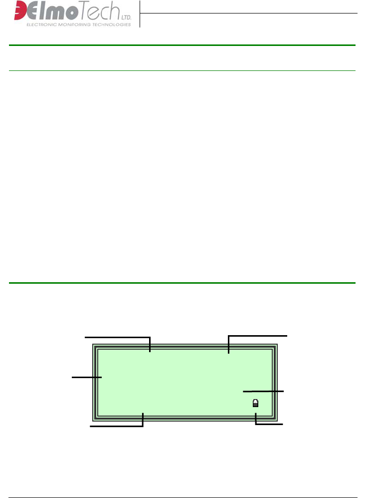
2.1.1 Display Panel
Mobile Unit Operational & Maintenance Guide
2-5
Tx 40193 03:46:56
Status: BD ST __ __
PR:16 OK:11 AB:2
▲ Menu ▼ Lock
Current Time
Tx ID Number
Tx Status
Indicator
Figure 2-2 LCD Display Panel
Global Status
Indicator
Battery Status
Menu/Command
Bar

Mobile Unit –User Manual
Mobile Unit Operational & Maintenance Guide
2-6
The LCD display panel indicators are explained, in detail, in the following
table:
Indicator Description
Tx ID Number Used to display the identification number of the
currently displayed transmitter (Tx)
Current Time Used to display the current time
Tx Status Indicator Used to display the status of the currently displayed
transmitter (Tx)
Global Status
Indicator
Used to display the global status of all transmitters
(the number of present transmitters, OK transmitters
and absent transmitters)
Menu/Command
Bar
Used to display the menu/command options
Battery Status Used to display the current battery level status
Before the Mobile Unit can be used to perform any its designated
monitoring tasks, the unit should be activated and the internal battery should
be fully charged.

Mobile Unit –User Manual
2.2 Activating the Mobile Unit
In order to activate the Mobile Unit, perform the following:
1. Press either the Up ▲ or Down ▼ buttons for approximately 3 seconds.
The Mobile Unit makes a number of audible beeping sounds, conducts
the initial series of built-in activation procedures and then the Start-Up
message (system logo; version number and current date) briefly appears
in the display panel.
Mobile Unit Operational & Maintenance Guide
2-7
Tx 40186 01:54:53
__ Status: BD ST __
:16 OK AB:2 PR :11
▲ Menu ▼ Lock
▌▐
MU System
Version 1.0
Sep 21 2003
Figure 2-3 The Start-Up message
2. Wait for the Search Mode view to appear in the display panel. This view
indicates that the Mobile Unit has been activated successfully.
Figure 2-4 The Search Mode View
2.3 Memory Management
Memory management is an integral part of the Mobile Unit setup and can be
applied in order to perform the following actions:
Delete the complete event log
Delete all existing members

Mobile Unit –User Manual
Mobile Unit Operational & Maintenance Guide
2-8
2.3.1 Deleting the Event Log
In order to delete the event log, perform the following steps:
1. Press the Up ▲ button to enter the Main menu. The Main menu is
displayed.
2. Press the Down ▼ button until the Memory Management (MEM) menu
option is highlighted.
3. Press the Up ▲ button to enter the Memory Management menu.
4. Press the Up ▲ button to delete the event log. A warning message
appears in order to confirm the deletion.
5. Press the Down ▼ button to confirm the deletion, or press the Up ▲
button to cancel.
6. Press the Down ▼ button until the ‘Return to Menu’ (←) menu option
is highlighted.
7. Press the Up ▲ button to return to the Main menu.
2.3.2 Deleting all Existing Members
In order to delete all existing members, perform the following steps:
8. Press the Up ▲ button to enter the Main menu. The Main menu is
displayed.
9. Press the Down ▼ button until the Memory Management (MEM) menu
option is highlighted.
10. Press the Up ▲ button to enter the Memory Management menu.
11. Press the Down ▼ button until the ‘Delete all Members’ (LST) menu
option is highlighted.
12. Press the Up ▲ button to delete the member list. A warning message
appears in order to confirm the deletion.
13. Press the Down ▼ button to confirm the deletion, or press the Up ▲
button to cancel.
14. Press the Down ▼ button until the ‘Return to Menu’ (←) menu option
is highlighted.
15. Press the Up ▲ button to return to the Main menu.

Mobile Unit –User Manual
Mobile Unit Operational & Maintenance Guide
2-9
2.4 Operational Mode Definition
During the Mobile Unit setup, operational mode definition can be applied in
order to define the actual operational mode of the Mobile Unit. The Mobile
Unit can be set to operate in the following modes of operation:
Search Mode – Used to display the current status of all transmitters within
range
Event Mode – Used to display new event message from all transmitters
within range (only applicable for group monitoring systems)
For a detailed description of the all the available operational modes, refer to,
Modes of Operation, located in the chapter about, Operating the Mobile
Unit.

Mobile Unit –User Manual
Mobile Unit Operational & Maintenance Guide
3-10
Chapter 3: Operating the Mobile
Unit
The Mobile Unit is a lightweight hand held unit that can be used by mobile
officers in the field to monitor offender transmitters.
3.1 Modes of Operation
The Mobile Unit can be used in the following modes of operation:
Search Mode – Used to display the transmitters identification number (Tx
ID), the current status of the transmitter (e.g. strap open, body off) and the
time of each reception. Search mode can be used in the following sub-
modes:
Search (Unlock) Mode – Used to display the current status of all
transmitters within range
Lock Mode – Used to display the current status of only the
currently selected (locked) transmitter
Event Mode – Used to display new event message from all transmitters
within range (only applicable for group monitoring systems)
Remote Mode – Used to upload stored data from the Mobile Unit to the
Mobile Monitoring System software application.
3.1.1 Monitoring in Search (Unlock) Mode
Once the Mobile Unit has been activated, the unit automatically enters into
Search mode.
For more information about activating the Mobile Unit, refer to the section
about, Activating the Mobile Unit, located at the beginning of this guide.

Mobile Unit –User Manual
Whenever the status of a monitored transmitter (transmitter within range)
changes, the Mobile Unit makes a beeping sound, the right LED lights up
and the new status is displayed in the display panel.
Mobile Unit Operational & Maintenance Guide
3-11
Tx 40186 01:54:53
__ Status: BD ST __
:16 OK AB:2 PR :11
▲ Menu ▼ Lock
Figure 3-1 Search (Unlock) Mode View
Once the status of the first monitored transmitter (transmitter within range)
appears in the display panel, the following information is displayed; the
identification number of the currently displayed transmitter (Tx ID), the
current time, the status of the currently displayed transmitter (e.g. strap
open, body off) as well as the global status of all transmitters (the number of
present transmitters, status OK transmitters and absent transmitters).
3.1.2 Monitoring in Lock Mode
Once the Mobile Unit starts to receive and display the status of more than
one monitored transmitter (transmitter within range), you can lock the
Mobile Unit onto a particular transmitter using lock mode. Once in lock
mode, the Mobile Unit will only display status information for the selected
(locked) transmitter.
3.1.2.1 Locking the Mobile Unit onto a Transmitter
In order to lock the Mobile Unit onto a specific transmitter, perform the
following steps:
16. Wait until the required transmitter identification number (Tx ID) is
displayed in the display panel.

Mobile Unit –User Manual
17. Press the Down ▼ button once to lock the Mobile Unit onto the selected
transmitter. The status of the selected transmitter is displayed in the
Display panel.
Mobile Unit Operational & Maintenance Guide
3-12
Tx 40186 L 01:54:53
Status: BD ST __ __
>Range: Medium >>>>>
▲ Menu ▼ Unlock
Figure 3-2 Lock Mode View
Once the Mobile Unit has locked onto the selected transmitter, the following
information is displayed; the identification number of the currently
displayed transmitter (Tx ID), the lock indicator (L), the current time, the
status of the currently displayed transmitter (e.g. strap open, body off) as
well as the approximate distance between the Mobile Unit and the locked
transmitter (e.g. short, medium, long).
18. Press the Down ▼ button once to unlock the transmitter. The Mobile
Unit enters back into Search mode.
3.1.3 Remote Mode
Once you have completed a monitoring session, you have the capability to
upload any stored data from the Mobile Unit to the Mobile Monitoring
System software application. This can be achieved in Remote mode.
3.1.3.1 Activating Remote Mode
Before the upload process can commence the Mobile Unit’s Remote mode
should be activated.
In order to activate Remote mode, perform the following steps:
19. Press the Up ▲ button to enter the Main menu. The Main menu is
displayed.

Mobile Unit –User Manual
20. Press the Down ▼ button until the Remote menu item (REM) has been
selected.
21. Press the Up ▲ button to enter the Remote menu. Remote mode is
automatically activated and the Mobile Unit is now ready for the upload
process to commence.
Mobile Unit Operational & Maintenance Guide
3-13
<< PC Remote Mode >>
▲ Exit
Figure 3-3 PC Remote Mode
For detailed description about uploading stored data to the Mobile
Monitoring System application, refer to the section about, Uploading
Stored Data from the Mobile Unit, located in the Mobile Monitoring
System-Monitor Operator’s Manual.
22. Press the Up ▲ button to exit Remote mode. The Mobile Unit enters
back into Search mode.
3.2 Charging the Mobile Unit
The Mobile Unit is supplied with a built-in rechargeable battery. In order to
keep the internal battery fully charged, you will need to connect the Mobile
Unit to the supplied charging adapter whenever the unit is not in immediate
use.
Note that, whenever the Mobile Unit is low on power, the low battery status
indicator located in the display panel flashes.

Mobile Unit –User Manual
Mobile Unit Operational & Maintenance Guide
3-14
3.2.1 Charging the Mobile Unit in the Home/Office
In order to charge the Mobile Unit in the home or office perform the
following steps:
23. Plug the appropriate end of the supplied power adapter (charger) into the
wall socket.
24. Connect the other end of the power adapter into the charger socket on
the Mobile Unit. The ‘Charging in Progress’ message is displayed in the
Display panel and the left LED indicator on the Mobile Unit lights up.
3.2.2 Charging the Mobile Unit in a Vehicle
In order to charge the Mobile Unit in a vehicle perform the following steps:
25. Plug the appropriate end of the supplied power adapter (charger) into the
vehicles cigarette lighter power outlet.
26. Connect the other end of the power adapter into the charger socket on
the Mobile Unit. The ‘Charging in Progress’ message is displayed in the
Display panel and the left LED indicator on the Mobile Unit lights up.

Mobile Unit –User Manual
Chapter 4: Maintaining the Mobile
Monitoring System
In order to keep the Mobile Monitoring System functional and in good
working order a number of maintenance procedures will need to be adhered
to.
4.1 Cleaning the Mobile Unit
To clean the Mobile unit, perform the following:
27. Remove the Mobile unit from its water resistant carrying pouch and
simply wipe the outside of the unit with a damp cloth.
Do not, under any circumstances, submerge or place the Mobile unit
under running water.
28. Using a piece of cloth or a paper towel, dry the outer side of the Mobile
unit.
29. Once the Mobile Unit is dry, place it into the water resistant pouch and
then into the specially designed transportation case.
4.2 Cleaning the Transmitter
The Transmitter is made of a single mold, especially designed to protect the
integrity of the electronic circuits during daily use and while it is being
cleaned. A soft brush and an alcohol based solution; soapy water or Lysol
can be used to clean the transmitter.
For additional safety and user comfort, it is recommended that after
cleaning with any of the above-mentioned solutions, you wash and wipe the
transmitter with clear water before it is re-used.
Mobile Unit Operational & Maintenance Guide
4-15

Mobile Unit –User Manual
To clean the transmitter, perform the following:
30. Remove the ‘female’ clip and strap holder from the transmitter short
strap.
31. If the storage clip is on, remove it until you finish cleaning the
transmitter.
32. Holding the transmitter by the end of the long strap, spray the
transmitter with a cleaning solution of choice.
33. Using a piece of cloth or a paper towel, dry the outer side of the
transmitter. Lay the transmitter on the towel with its inner side facing
up. Using a soft brush or a piece of cloth/towel, gently scrub the inner
side of the transmitter along the tracks.
34. Wash the transmitter in clear water.
35. Dry the transmitter using a piece of cloth/paper towel or simply let it
drip dry.
36. Once the transmitter is dry, place it into the specially designed
transportation case.
4.3 Replacing the Transmitter Straps
After some time and depending on the wear and tear of the transmitter, the
straps on the transmitter will need to be replaced. Any of the following
points could justify replacing a transmitter strap:
Visible damage to one or both straps
Unexplainable strap tamper alarms
Transmitter will not calibrate
Note that if only one side of the strap is damaged, you may want to
leave the undamaged side in place and replace only the damaged side of the
strap.
Check that you have the following equipment items before you replace the
transmitter straps:
1 transmitter body
Mobile Unit Operational & Maintenance Guide
4-16

Mobile Unit –User Manual
1 pair of replacement straps (long/medium non-pins side and long/medium
pins side)
Screwdriver
Extra screws
• Extra strap clips (male and female)
Electronic key
To replacing the transmitter straps, perform the following:
37. Using the screwdriver, open the screw(s) that holds the strap clasp to the
transmitter and remove the strap clasp.
38. Gently shake the strap loose from the transmitter body, being extra
careful not to damage the metal pins on the transmitter body.
39. Position the new strap over the transmitter body. Notice that the two
small holes on the strap have to lie exactly over the two metal pins.
40. Gently place the strap down over the metal pins and press down along
the seam of the strap, snugly fitting the entire strap to the transmitter
body.
41. Put the strap clasp back in place with the wider side pointing in-wards.
42. Close the screw (s) with the screwdriver. It has to be closed firmly, but
not too tight since this can damage the strap.
43. Test the new strap by performing a calibration.
If, after the calibration, the transmitter does not reset, repeat steps 1-6
making sure that the strap is positioned correctly over the pins. Then
perform another calibration test. If changing only one side of the strap does
not work, you should try and change the other strap side.
Mobile Unit Operational & Maintenance Guide
4-17

Mobile Unit –User Manual
Mobile Unit Operational & Maintenance Guide
5-18
Chapter 5: Mobile Monitoring
System Specifications
This chapter lists the specifications details for each equipment item
associated with the Mobile Monitoring system.
5.1 Mobile Unit Specifications
This section of the Mobile Monitoring System specifications chapter is
divided into the following sections:
Mobile Unit Features
Light, palm sized and water-
resistant new design
Ability to verify monitored
offender compliance while
patrolling in a vehicle, or on foot
Minimizing direct unnecessary
contact with offenders
Extended memory capacity
Windows™ PC interface, for
batch report processing
The groundbreaking GPS model
will report the offender’s location
and immediately upload this
information to the monitoring
center
Memory
Store and monitor up to 200
transmitters
Log up to 3000 events
Records are time stamped
Operating Characteristics
Battery Life between charges: 16-
24 hours
Charge Time: 5 hours

Mobile Unit –User Manual
Mobile Unit Operational & Maintenance Guide
5-2
Mechanical Characteristics
Water Resistant
Size: 14 x 8.5 x 3.5 cm (5.5 x 3.3 x 1.4 in)
Antenna length: 8.5 cm (3.3 in)
LCD message display
Backlight push button
Acknowledge push button
Waterproof pouch with belt clip.