Attenti SBU2000433-2 2Track Base Unit 433 MHz User Manual
3M Electronic Monitoring, Inc. 2Track Base Unit 433 MHz
UserManual.wiki
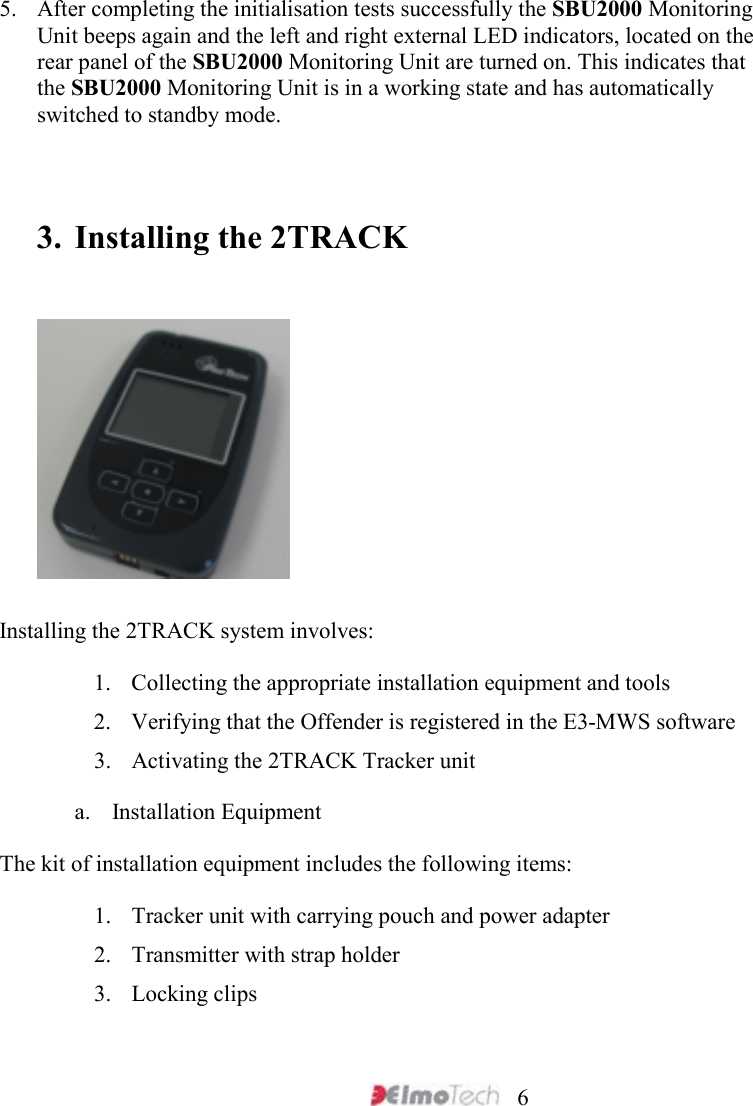
>
Attenti
>
SBU2000433 2 User Manual
User Manual
Navigation menu
Upload a User Manual
Namespaces
Wiki Guide
HTML
PDF
Info
Views
User Manual
Discussion / Help
Navigation