Attenti STAR-800-2 Mobile Monitoring Unit User Manual STaR unit and Transmitter
3M Electronic Monitoring, Inc. Mobile Monitoring Unit STaR unit and Transmitter
Attenti >
User Manual

Receiver and Transmitter
Installation and Operation Guide

Information in this documentation is subject to change without
notice and does not represent a commitment on part of
Elmo-Tech Ltd. The software described in this document is
subject to the license agreement that is included with the
product, which specifies the permitted and prohibited uses of
the product. Any unauthorized duplication or use of this
documentation, in whole or in part, in print, or in any other
storage or retrieval system is prohibited.
No part of this publication may be reproduced, transmitted,
transcribed, stored in a retrieval system, or translated into any
language in any form by any means for any purpose other than
the purchaser’s personal use without the permission of
Elmo-Tech Ltd.
© 2002-07 Elmo-Tech Ltd. All rights reserved.
Unless otherwise noted, all names of companies, products,
street addresses, and persons contained herein are part of a
completely fictitious scenario and are designed solely to
document the use of an Elmo-Tech product.
Contact Us
Corporate Headquarters
Elmo-Tech Ltd.
2 Ha-Barzel St.,
P.O. Box 13236,
61132 Tel Aviv, Israel
Tel: 972-3-7671800
Fax: 972-3-7671801
U.S.A Customers, call 1-800-313-1483
E-mail: contact@elmotech.com
Visit us at: www.elmotech.com

Table of Contents
1 Introduction.................................................................... 1
About STaR®.................................................................... 1
2 Getting Started ............................................................... 3
About This Manual ............................................................ 3
3 Pre-Installation and Equipment Requirements ............... 5
Pre-Installation Procedures................................................. 5
Equipment Requirements ................................................... 6
4 Home Unit Installation & Activation Instructions............ 7
Locating the Home Unit ..................................................... 8
Activating the Home Unit ................................................... 8
5 Transmitter Activation & Installation Instructions........ 11
Activating the Transmitter.................................................11
Attaching the Transmitter .................................................12
6 STaR Unit Activation & Operational Instructions........... 15
Parts of the STaR Unit ......................................................15
Display Panel..............................................................16
Activating the STaR Unit ...................................................16
Navigating the Display Panel .............................................17
Initiating the Data Download .............................................17
Performing an End of Service to the Unit .............................18
Offender Rules and Operational Procedures..........................19
i

STaR Unit & Transmitter Installation and Operation Guide
General Rules for the Offender ......................................19
Acknowledging a Command Message ..................................20
Charging the STaR Unit ....................................................21
Defining STaR Unit Operational Settings..............................22
7 Maintaining & Packing the Monitoring Equipment......... 25
Cleaning the STaR Unit or Home Unit..................................25
Cleaning the Transmitter...................................................26
Replacing the Transmitter Straps .......................................28
8 FCC Information............................................................ 30
ii

List of Figures
iii
List of Figures
Figure 1 Home Unit................................................................... 7
Figure 2 Locating the Home Unit................................................. 8
Figure 3 STaR Unit Parts...........................................................15
Figure 4 Display Panel..............................................................16

1
1 Introduction
About STaR®
STaR (Satellite Tracking and Reporting) is based on highly
advanced GPS (Global Positioning Satellite) technology and
Elmo-Tech’s field proven RF monitoring expertise. The Home
Unit, the Transmitter and the STaR Unit are just a few of the
unique elements of the Electronic Monitoring System.
The monitored individual wears a body secured Transmitter. For
effective supervision, the monitored individual is assigned with a
personalized curfew schedule and a zone limitation program
(hot zones).
The STaR Unit is a mobile monitoring device that reports on
locality and infractions, helping to ensure absolute compliance in
accordance with the monitored individual’s appointed monitoring
program. While in the curfew location (e.g. home or hostel), the
STaR Unit is placed next to the Home Unit. The Home Unit
extends the STaR Unit’s reception capabilities in such a way as
to cover the entire curfew location.
When leaving the curfew location, the monitored individual must
carry the STaR Unit on his or her person. An alert is activated if
the Transmitter and the STaR Unit are separated. Once on the
move, the STaR Unit automatically acquires a GPS position fix
and activates continuous location data collection. The STaR Unit
communicates with the monitoring center, via the cellular
network, reporting on location and violations. Reporting is based
on the monitored individual’s assigned program and schedule.

2 Getting Started
About This Manual
The STaR Unit and Transmitter Installation and Operational
Guide has been created for the installation expert and is meant
as a guide through the STaR Unit & Transmitter installation and
operational procedures. This manual assumes that you have at
least some experience with electronic monitoring systems.
This manual does not contain information regarding system
settings, configuration or any other software produced by
Elmo-Tech Ltd., unless directly related to this produce.
Please refer to the appropriate manuals for information with
respect to the E3-MWS Monitor Operator and System
Administration manuals.
The STaR Unit and Transmitter Installation and Operation Guide
is divided into the following chapters:
f Introduction – Introduces you to the STaR monitoring
methodology.
f Pre-Installation and Equipment Requirements –
Describes the various pre-installation and equipment
requirements.
f Home Unit Installation & Activation Instructions –
Describes the various installation and activation procedures
with regard to the Home Unit.
f Transmitter Activation & Installation Instructions –
Describes the various activation and installation procedures
with regard to the Transmitter.
3

STaR Unit & Transmitter Installation and Operation Guide
4
f STaR Unit Activation & Operational Instructions –
Describes the various activation and operational procedures
with regard to the STaR Unit.
f Maintaining the Monitoring Equipment – Describes the
maintenance, replacement and packing procedures
regarding the monitoring equipment.
All STaR related hardware and software must be installed and
repaired by a qualified Elmo-Tech customer service
representative or an experienced system administrator.
Elmo-Tech Ltd is committed to innovation and continued
improvement. Upgrades may be announced that consist of
software improvements and updated manuals will generally
accompany those system changes.
3 Pre-Installation and Equipment
Requirements
Pre-Installation Procedures
While still at the monitor center or probation agency:
1. Enter the Offender’s personal information and the STaR Unit
configuration parameters into the Electronic Monitoring
System software application. You can perform this well in
advance, even before the actual monitoring equipment is
allocated and installed.
2. Enter the following equipment information into the Electronic
Monitoring System software application:
f STaR Unit serial number
f Home Unit serial number
f Transmitter serial number
3. Check that the serial numbers that you enter match the
numbers on each of the equipment items.
Note: The relevant serial numbers are visible on the back
or side of each equipment item.
5

STaR Unit & Transmitter Installation and Operation Guide
6
Equipment Requirements
Before leaving the monitor center or probation agency check
that you have:
f STaR Unit, carrying pouch and power adapter
f Transmitter (Tx) with Strap holder
f Home Unit and power adapter
f Electronic key
f Locking tool
f Locking clips (male and female)
f Screwdriver (to open the clips if necessary). It is
recommended to use a 0.2in (5mm) flat head screwdriver.
Note: It is always recommended to bring an extra set of
locking clips, in case the first set get accidentally damaged
during the installation.

4 Home Unit Installation & Activation
Instructions
Figure 1 Home Unit
7
STaR Unit & Transmitter Installation and Operation Guide
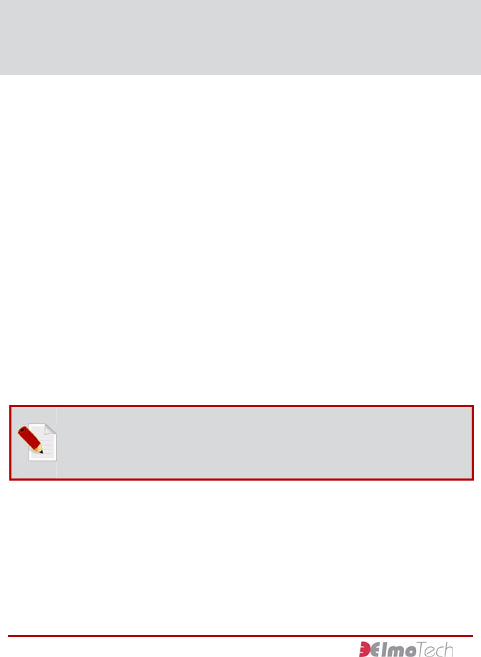
Locating the Home Unit
Place the Home Unit as close to the center of the curfew location
as possible, 3 ft (1 m) off the ground and at least 1 foot (30 cm)
away from the wall.
Figure 2 Locating the Home Unit
Activating the Home Unit
To activate the Home Unit:
Connect the adapter end of the external power cable to the
power outlet. The Home Unit makes three audible beeping
sounds. The Charge LED on the front panel flashes when the
Home Unit is first activated.
8

4 Home Unit Installation & Activation Instructions
9
The Charge and Power LED’s light up only after the backup
battery is fully charged. The Home Unit is now in monitoring
mode.
To deactivate the Home Unit:
1. Using a screwdriver, unscrew and remove the Unit holding
screw located on the underside of the mounting bracket.
2. Disconnect the Home Unit from the mounting bracket by
pulling the Unit upwards slightly.
3. Remove the Home Unit from the mounting bracket and turn
the Unit over. The deactivation button is located on the
backside of the Unit.
4. Using a pointed instrument (but not sharp), push down on
the reset button. The Home Unit deactivates itself and all
stored information is deleted.

5 Transmitter Activation & Installation
Instructions
Activating the Transmitter
To activate the Transmitter:
1. Hold the Transmitter in the palm of your hand with the
metal pins, along the strap, pointing towards you. You will
need to support the underside of the strap with your finger.
2. Hold the MRD (Manual Reset Device) in your free hand, with
the Off button facing towards the open end of the strap. The
On button must be facing the main body of the Transmitter.
3. Press the MRD down over the strap ensuring that the two
metal touch points on top of the MRD make contact with the
two metal pins on the strap.
4. Holding the MRD in this position, press the On button for
one second. The red LED on the MRD turns steadily on for
two seconds, followed by two seconds of flashing. This
indicates that the Transmitter has received the activation
command.
5. Place the Transmitter on its side, onto a non-metal surface
and wait for 30 seconds.
6. Once activated, you can attach the Transmitter to the
monitored individual’s wrist or ankle.
Remember: For more information about attaching the
Transmitter, refer to the section about, Attaching the
Transmitter.
11
STaR Unit & Transmitter Installation and Operation Guide
To deactivate the Transmitter:
Follow the instruction, as described in the steps on the previous
page and instead of pressing the MRD On button to activate the
Transmitter, press the Off button.
Attaching the Transmitter
To attach the Transmitter to the monitored individual’s
wrist or ankle:
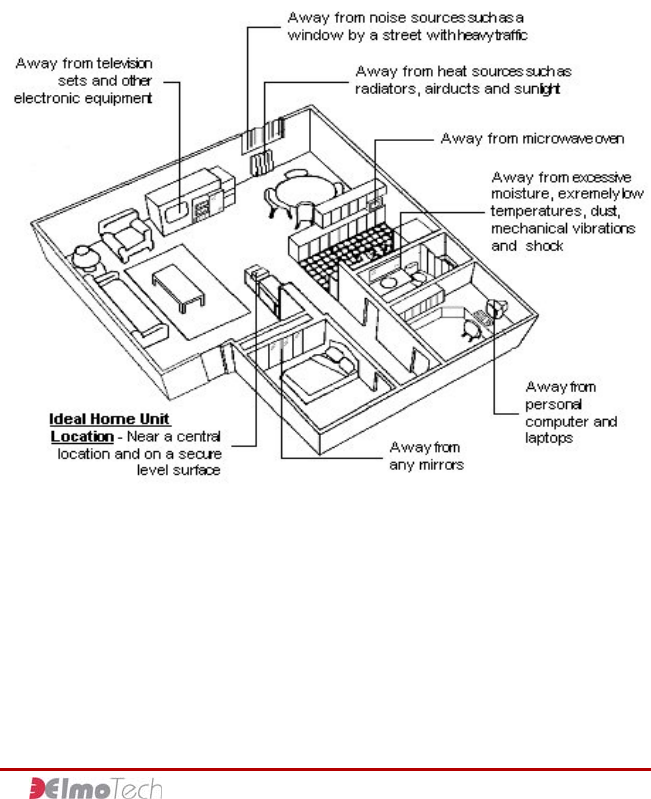
1. Place the strap holder
onto the short strap
(pin side) of the
transmitter.
2. Attach the female clip
to the underside of
the short strap and
verify that the closed
end of the female
clip fits with the
edge of the strap.
3. Wrap the Transmitter around the monitored individual’s
wrist or ankle at its narrowest point.
12
5 Transmitter Activation & Installation Instructions
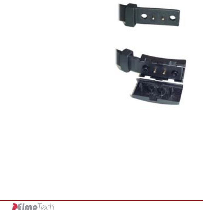
4. Position the long
strap over the
female clip,
ensuring that all
the pins on the
short strap
protrude through
the long strap.
5. Slide the strap holder over the end of the long strap in
order to hold it in place.
6. Press the male
clip down onto
the female clip,
ensuring that all
pins and
grooves, on both
locking clips,
connect
correctly.
7. Get the monitored individual to move around with the
Transmitter around the wrist or ankle and ensure that
the strap fits comfortably.
Note: The closed strap should not put any pressure on the
wrist or ankle. For a leg attachment, try to attach the
Transmitter over a sock before fastening the clips.
8. Fasten the two clips together using the supplied locking
tool. An audible clicking sound is heard indicating that
the strap clips are secured together correctly.
13

STaR Unit & Transmitter Installation and Operation Guide
14
To remove the Transmitter from the monitored
individual’s wrist or ankle:
Place the sharp end of a flat head screwdriver into the open
groove on the side of the locking clip and applying a little
pressure, break the locking clips apart. You can now remove the
Transmitter from the monitored individual’s wrist or ankle.
6 STaR Unit Activation & Operational
Instructions
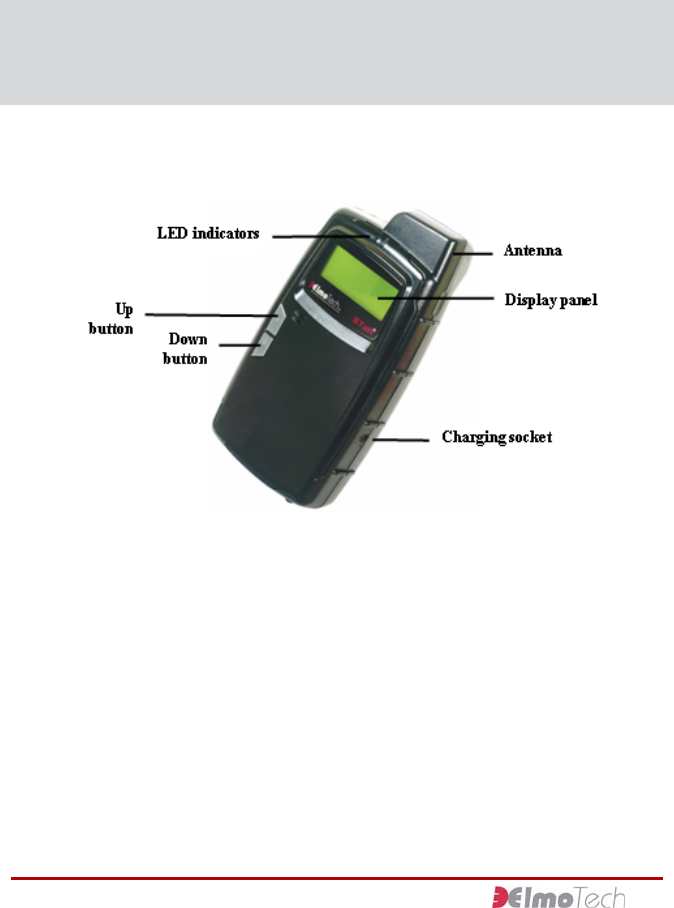
Parts of the STaR Unit
Figure 3 STaR Unit Parts
15
STaR Unit & Transmitter Installation and Operation Guide
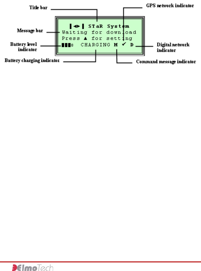
Display Panel
Figure 4 Display Panel
Activating the STaR Unit
To activate the STaR Unit:
1. Connect one end of the power adapter into the wall socket
and connect the other end into the charging socket on the
STaR Unit.
2. Once activated the STaR Unit makes an audible beeping
sound, the system logo, version number and current date
and time are briefly displayed in the Display panel. The
‘Waiting for Download’ message is then displayed in the
Display panel, indicating that the STaR Unit has been
activated successfully.
To deactivate the STaR Unit:
1. Press the Up and Down buttons simultaneously until the
Display panel goes blank.
2. Release the Up and Down buttons. An ‘Insert Password’
message is displayed.
16

6 STaR Unit Activation & Operational Instructions
3. Insert the relevant password into the appropriate field. You
can enter a number by pressing the Up button until the
desired number is displayed. Press the Down button to set
the displayed number and then move onto the next number.
Continue until the correct password is displayed.
4. Press the Up and Down buttons on the STaR Unit
simultaneously until the Shutdown option is displayed.
5. Select Shutdown. The Shutdown options are displayed.
6. Select the Turn Off option. The Display panel turns blank,
indicating that the STaR Unit has been deactivated
successfully.
Navigating the Display Panel
The Control bar is located in the lower section of the Display
panel and can be used to navigate through the control options in
the Display panel.
The Up and Down buttons on the STaR Unit can be used to
navigate the Control bar and select control options in the
Display panel.
Remember: For a detailed view of the Display panel, refer
to the section about, Display panel.
Initiating the Data Download
To initiate the data download:
1. With the ‘Waiting for Download’ message and the digital
network indicator (D) all displayed in the Display panel,
make a call to the monitoring center.
2. Relay the defined Tx and Home Unit ranges to the
17

STaR Unit & Transmitter Installation and Operation Guide
monitoring center personnel and ask them to adjust the In-
House and Outside range settings, located in the monitoring
workstation software application, accordingly.
3. Request a manual download. Once performed, the
monitoring center will call back to confirm a successful
download, or to inform you that the download has failed and
should be initiated again. Once the manual download has
been deemed successful, a ‘Start Monitoring’ message is
displayed in the Display panel. This indicates that the STaR
Unit is in pre-monitoring mode.
4. Select Start to activate monitoring mode.
Note: Monitoring mode will only start if the monitored
individual’s program start date, as defined in the monitoring
workstation software application, has arrived.
Performing an End of Service to the Unit
Once the monitored individual’s monitoring program has been
completed and before you deactivate the STaR Unit, the end of
service procedure should be performed. The end of service
procedure erases the STaR Unit’s memory.
A full End of Service procedure must be performed through the
E3 Electronic Monitoring System. The following procedure
describes an End of Service to the STaR Unit only.
To perform an end of service:
1. Press the Up and Down buttons on the STaR Unit
simultaneously until the Display panel goes blank.
2. Release the Up and Down buttons. An ‘Insert Password’
message is displayed.
3. Insert the relevant password into the appropriate field. You
can enter a number by pressing the Up button until the
desired number is displayed. Press the Down button to set
18
6 STaR Unit Activation & Operational Instructions
the displayed number and then move onto the next number.
Continue until the correct password is displayed.
4. Press the Up and Down buttons on the STaR Unit
simultaneously until the Shutdown option is displayed.
5. Select Shutdown. The Shutdown options are displayed.
6. Select the End of Service (EOS) option. The STaR Unit
makes an audible beeping sound, the system logo, version
number and current date and time are briefly displayed in
the Display panel. The ‘Waiting for Download’ message is
then displayed in the Display panel, indicating that the STaR
Unit has been end of serviced successfully.
7. You can now deactivate the STaR Unit.
Remember: For information about deactivating the STaR
Unit, refer to the section about, Activating the STaR Unit.
Offender Rules and Operational Procedures
There are number of rules and operational procedures that the
monitored individual must observe and perform in accordance
with his or her monitoring program.
General Rules for the Offender
The monitored individual must abide by the following
rules:
f Always take the STaR Unit with you, whenever you leave
your place of residence or place of work
f Always wait until the GPS network indicator (9) is displayed
in the Display panel, before entering a building
f Always place the STaR Unit on a flat surface facing up
whenever you enter your place of residence or place of work
19

STaR Unit & Transmitter Installation and Operation Guide
f Always connect the STaR Unit to the charging adapter
whenever you are traveling in a vehicle, in your place of
residence or in your place of work
f Whenever you hear the audible beeping sound you must
read the command message displayed in the Display panel
f Whenever you receive a command message and are
instructed to perform a task, you must comply
f Whenever you receive a command message, you must
select Acknowledge to acknowledge the receipt and
compliance of the command message
f Never touch or move the Home Unit once it has been
installed
f Never place any objects on top of the Home Unit
f Never disconnect the power cord from either the Home
Unit, or the wall socket
f Never attempt to open the Home Unit
f Never attempt to open the STaR Unit carrying pouch
f Never attempt to open the STaR Unit
f Never move out of the designated curfew area during an in-
house curfew time frame
f Never move away from the STaR Unit when away from the
curfew location
f Never attempt to open the Transmitter strap clip
f Never attempt to cut or break the Transmitter strap
Acknowledging a Command Message
Upon certain predefined violations, the STaR Unit activates an
audible beeping sound, the LED flashes and a command
message is displayed in the Display panel. The audible beeping
sound and flashing LED will continue until the requested
20
6 STaR Unit Activation & Operational Instructions
command is completed and the command message has been
acknowledged.
To acknowledge a command message:
Complete the requested command and then press the Up button
to acknowledge.
Charging the STaR Unit
In order to keep the STaR Unit fully charged and operational,
the monitored individual should connect the Unit to the supplied
charging adapter whenever the Unit is not in immediate use.
To charge the STaR Unit:
1. Connect the appropriate end of the supplied charging
adapter into either, the wall power socket, or the vehicle’s
cigarette lighter power outlet.
2. Connect the small end of the charging adapter into the
charging socket located on the STaR Unit. The left LED
indicator lights up and a Charging message is displayed in
the Display panel, indicating the STaR Unit is in charging
mode.
Note: If the STaR Unit is connected for charging while the
actual Unit is off, the Unit automatically activates itself and
charging commences.
Warning! In case of the following:
f The LCD indicator blinks irregularly
f The Unit unpredictably turns off and resets itself
f Any other irregular actions
Please disconnect and turn off, and return it to the
monitoring agency/supplier for replacement. Do not attempt
21

STaR Unit & Transmitter Installation and Operation Guide
to fix the Unit by yourself.
For agencies/customers: Do not use faulty Units at any
time. If any of the above malfunctions occur, return the Unit
to Elmo-Tech for repair.
Defining STaR Unit Operational Settings
To define STaR Unit operational settings:
1. With the ‘Waiting for Download’ message displayed in the
Display panel, press the Up button on the STaR Unit. A ‘Test
GPS?’ message is displayed.
2. Move, with the STaR Unit to a place just outside the
monitored individual’s accommodation in order to receive a
reasonable GPS position fix.
3. Select Start and wait until the appropriate GPS position fix is
acquired. A ‘GPS OK’ message is displayed.
4. Select Abort and then select Skip to navigate to the next
setting test. A ‘Test Modem?’ message is displayed.
5. Select Start and wait until the modem powers up. A ‘Modem
Power Up OK’ message is displayed.
6. Move around the curfew location in order to receive a
reasonable digital network connection.
7. Select Exit to exit the modem test. A ‘Test Tx & HU?’
message is displayed.
8. Select Start and then insert the Tx serial number into the
appropriate field. You can enter a number by pressing the
Up button until the desired number is displayed. Press the
Down button to set the displayed number and then move
onto the next number. Continue until the full Tx serial
number is displayed.
9. Press the Up and Down buttons on the STaR Unit
simultaneously until the ‘Searching for Tx’ message is
22
6 STaR Unit Activation & Operational Instructions
displayed.
10. Activate the Transmitter and place it at the appropriate
maximum free movement distance from the STaR Unit.
Remember: For more information about activating the
transmitter, refer to the section about, Installing the
Transmitter.
11. Wait for the defined Tx range to be displayed in the Display
panel. You will need to relay the registered Tx range to the
monitoring center before the first download is performed.
This range will be defined as the maximum free movement
area in which the monitored individual can move away from
the STaR Unit while not at home.
12. Select Next to move to the next setting test. A ‘Home Unit
range’ message is displayed.
13. Activate the Home Unit.
Remember: For more information about installing and
activating the Home Unit, refer to the section about,
Installing the Home Unit.
14. Place the STaR Unit into the cradle next to the Home Unit.
15. Move, with the Transmitter in your hand, to the following
curfew places:
f Places most distant from the Home Unit.
f Places behind large metal objects.
f Places where the monitored individual may spend long
periods of time like the bedroom or living room.
f Remote locations like the garage, cellar or garden.
23
STaR Unit & Transmitter Installation and Operation Guide
24
Note: the Transmitter should be situated at least
2 minutes in each location in order for the STaR Unit to
receive a true Home Unit range setting.
16. Wait for the defined Home Unit range setting to be displayed
in the Display panel. You will need to relay the highest of all
the registered Home Unit ranges to the monitoring center
before the first download is performed. This range will be
defined as the maximum free movement area in which the
monitored individual can move away from the Home Unit
while at home.
17. Select Stop to stop the Home Unit range setting test.
18. Select Next. A ‘Test finished’ message is displayed.
19. Select Exit to exit the STaR Unit settings, or select Retest to
restart and redefine the STaR Unit settings. The STaR Unit
makes an audible beeping sound, the system logo, version
number and current date and time are briefly displayed in
the Display panel. The ‘Waiting for Download’ message and
the digital network indicator (D) are all displayed in the
Display panel. This indicates that the STaR Unit’s settings
have been defined correctly and the Unit has been re-
activated successfully.
20. Attach the Transmitter to the monitored individual’s wrist or
ankle.
Remember: For more information about attaching the
transmitter refer to the section about, Attaching the
Transmitter.
7 Maintaining & Packing the Monitoring
Equipment
Regular cleaning of your Elmo-Tech equipment is recommended,
using Elmo-Tech approved products.
After cleaning, Elmo-Tech recommends that you perform a
visual inspection of all Units to check for cracks or any other
damage, before redeploying into the field
Cleaning the STaR Unit or Home Unit
To clean the STaR Unit or Home Unit:
1. Remove the Unit from its carrying case.
2. Spray the surface of the Unit with an alcohol based cleaner
(optional).
Note Elmo-Tech recommends Citrus Base cleaner by 3M™
(http://solutions.3m.com/).
3. Using a damp cloth, wipe the outside of the Unit.
Caution: Do not, under any circumstances, submerge or
place the Unit under running water.
4. Using a dry cloth, or paper towel, dry the outside of the
Unit.
5. Once the Unit is dry, return it to its carrying case.
25

STaR UNIT & TRANSMITTER INSTALLATION AND OPERATION GUIDE
Cleaning the Transmitter
The following Transmitter cleaning methods are approved by
Elmo-Tech:
f Manual Cleaning – using a soft brush and approved cleaning
product.
f Using a Dishwasher – together with an approved cleaning
product.
To clean the Transmitter manually:
1. Remove the Transmitter from its carrying case.
2. If there are clips on the Transmitter, remove the ‘female’
and ‘male’ parts before cleaning.
3. Remove the strap holder from the Transmitter.
4. Hold the Transmitter by the end of the long strap and either:
f Spray the Transmitter with 3MTM Citrus Base cleaner, or
an alcohol based equivalent.
Or
f Using a damp cloth or towel, clean the Transmitter with
soapy water.
5. Using a dry cloth or towel, dry the outside of the Transmitter
and place it on a towel with its inner side facing up.
6. Using a soft brush, gently brush the inner side of the
Transmitter along the tracks.
7. After cleaning, wash the Transmitter in clean water.
8. Using a dry cloth or towel, dry the Transmitter thoroughly.
9. Place the strap holder back on to the short strap of the
Transmitter.
10. Place the Transmitter back into its carrying case.
26

7 Maintaining & Packing the Monitoring Equipment
To clean the Transmitter using a dishwasher:
1. Remove the Transmitter from its carrying case.
2. If there are clips on the Transmitter, remove the ‘female’
and ‘male’ parts before cleaning.
3. Remove the strap holder from the Transmitter.
4. Place the Transmitter into the dishwasher machine.
5. Use a pH neutral or slightly acidic cleaning agent.
Note: Elmo-Tech recommends Hepi dishwashing Products
by Thurn-produckte (http://www.thurn-produkte.de/).
6. Choose the shortest cycle, at a maximum temperature of
52ºC.
7. Once the Transmitter is dry, place the strap holder back
onto the short strap of the Transmitter.
8. Place the Transmitter back into its carrying case.
27
STaR UNIT & TRANSMITTER INSTALLATION AND OPERATION GUIDE
Replacing the Transmitter Straps
Any of the following indicator’s could justify replacing a
Transmitter strap:
f Visible damage to one or both straps
f Strap tamper alarm generated, with no visible damage to
the Transmitter
f Transmitter will not activate
Note: If only one side of the strap is damaged, you may
want to leave the undamaged side in place and replace only
the damaged side of the strap.
The following equipment items are required to replace the
Transmitter straps:
f 1 Transmitter body
f 1 pair of replacement straps (long/medium non-pins side
and long/medium pins side)
f Screwdriver
f Extra screws
f Extra strap clips (male and female)
f Electronic key
To replace the Transmitter straps:
1. Using the screwdriver, open the screw(s) that holds the
strap clasp to the Transmitter and remove the strap clasp.
2. Gently shake the strap loose from the Transmitter body,
being extra careful not to damage the metal pins on the
Transmitter body.
28

7 Maintaining & Packing the Monitoring Equipment
3. Position the new strap over the Transmitter body. Notice
that the two small holes on the strap have to lie exactly over
the two metal pins.
4. Gently place the strap down over the metal pins and press
down along the seam of the strap, snugly fitting the entire
strap to the Transmitter body.
5. Put the strap clasp back in place with the wider side pointing
in-wards.
6. Close the screw (s) with the screwdriver. It has to be closed
firmly, but not too tight since this can damage the strap.
7. Test the new strap by re-activating the Transmitter.
8. If, after the re-activation, the Transmitter does not reset
itself, repeat steps 1-6 making sure that the strap is
positioned correctly over the pins. Then perform another
activation test. If changing only one side of the strap does
not work, you should try and change the other strap side.
29

STaR UNIT & TRANSMITTER INSTALLATION AND OPERATION GUIDE
8 FCC Information
FEDERAL COMMUNICATIONS COMMISSION (FCC) Part 15 STATEMENT
This equipment has been tested to FCC requirements and has been found acceptable for
use. The FCC requires the following statement for your information.
This equipment generates and uses radio frequency energy and if not installed and used
properly, that is, in strict accordance with the manufacturer’s instructions, may cause
interference to radio and television reception. It has been type tested and found to comply
with the limits for a Class B computing device in accordance with the specifications in Part
15 of FCC Rules, which are designed to provide reasonable protection against such
interference in a residential installation. However, there is no guarantee that interference
will not occur in a particular installation. If this equipment does cause interference to radio
or television reception, which can be determined by turning the equipment off and on, the
user is encouraged to try to correct the interference by one or more of the following
measures:
• If using an indoor antenna, have a quality outdoor antenna installed.
• Reorient the receiving antenna until interference is reduced or eliminated.
• Move the receiver away from the control/communicator.
• Move the antenna leads away from any wire runs to the control/ communicator.
• Plug the control/communicator into a different outlet so that it and the receiver
are on different branch circuits.
If necessary, the user should consult the dealer or an experienced radio/television
technician for additional suggestions.
The user or installer may find the following booklet prepared by the Federal
Communications Commission helpful: “Interference Handbook”. This booklet is available
from the U.S. Government Printing Office, Washington, DC 20402.
The user shall not make any changes or modifications to the equipment unless authorized
by the Installation Instructions or User’s Manual. Unauthorized changes or modifications
could void the user’s authority to operate the equipment.
30

8 FCC Information
31
TRANSMITTER FEDERAL COMMUNICATIONS COMMISSION (FCC)
Part 15 STATEMENT
The equipment complies with Part 15 of the FCC Rules.
Operation is subject to the following two conditions:
(1) This device may not cause harmful interference, and (2) This device must accept any
interference received, including interference that may cause undesired operation.
This equipment has been tested and found to comply with the limits for a Class B digital
device, pursuant to part 15 of the FCC Rules. These limits are designed to provide
reasonable protection against harmful interference in a residential installation. This
equipment generates, uses and can radiate radio frequency energy and, if not installed
and used in accordance with the instructions, may cause harmful interference to radio
communications. However, there is no guarantee that interference will not occur in a
particular installation. If this equipment does cause harmful interference to radio or
television reception, which can be determined by turning the equipment off and on, the
user is encouraged to try to correct the interference by one or more of the following
measures:
1. Reorient or relocate the receiving antenna, 2. Increase the separation between the
equipment and the receiver, 3. Connect the equipment into an outlet on a circuit different
from that to which the receiver is connected, 4. Consult the dealer or an experienced
radio/TV technician for help.