Attenti TRXS-840-2 Bracelet Transmitter User Manual
3M Electronic Monitoring, Inc. Bracelet Transmitter Users Manual
UserManual.wiki
>
Attenti
>
TRXS 840 2 User Manual
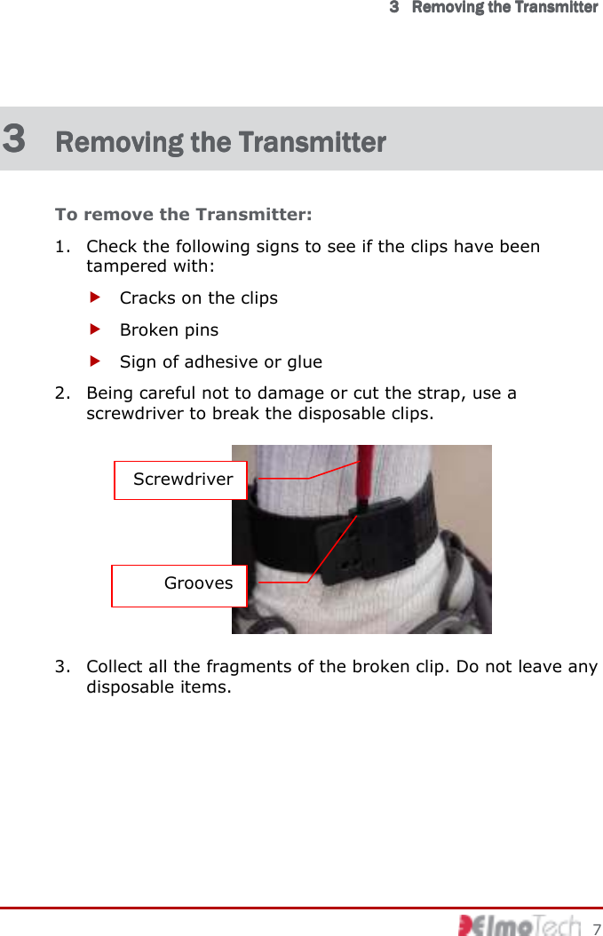
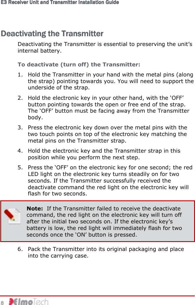
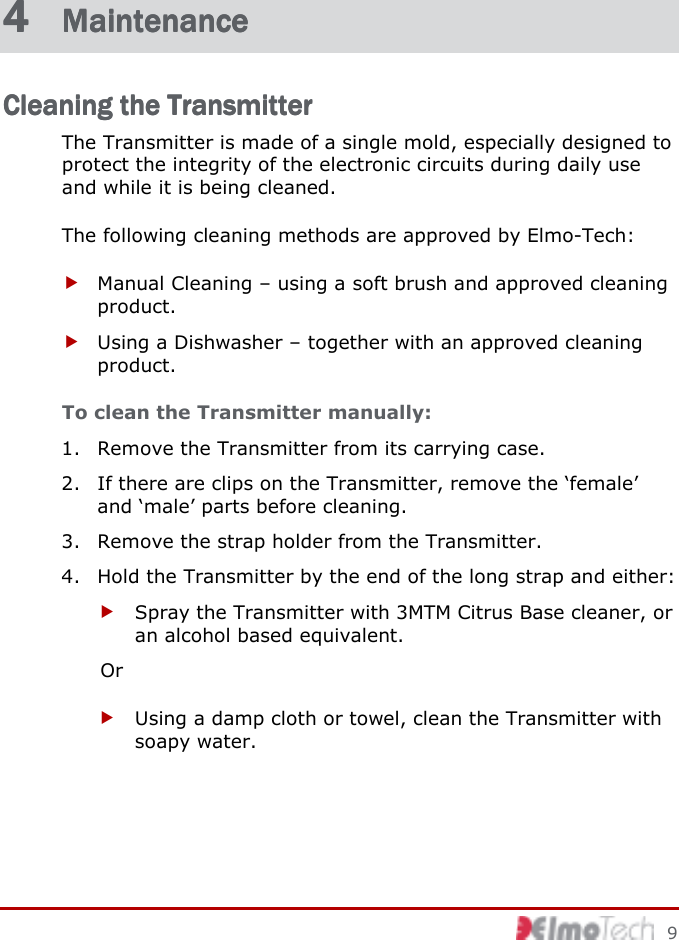
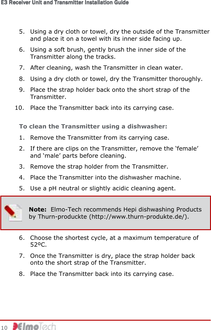
Users Manual
Navigation menu
Upload a User Manual
Namespaces
Wiki Guide
HTML
PDF
Info
Views
User Manual
Discussion / Help
Navigation